EP1247423B1 - Hearing aid remote control and a hearing aid with a remote control of this type - Google Patents
Hearing aid remote control and a hearing aid with a remote control of this typeDownload PDFInfo
- Publication number
- EP1247423B1 EP1247423B1EP00900199AEP00900199AEP1247423B1EP 1247423 B1EP1247423 B1EP 1247423B1EP 00900199 AEP00900199 AEP 00900199AEP 00900199 AEP00900199 AEP 00900199AEP 1247423 B1EP1247423 B1EP 1247423B1
- Authority
- EP
- European Patent Office
- Prior art keywords
- unit
- remote control
- battery
- khz
- coil arrangement
- Prior art date
- Legal status (The legal status is an assumption and is not a legal conclusion. Google has not performed a legal analysis and makes no representation as to the accuracy of the status listed.)
- Expired - Lifetime
Links
- 230000006870functionEffects0.000claimsdescription9
- 230000000007visual effectEffects0.000claimsdescription4
- HBBGRARXTFLTSG-UHFFFAOYSA-NLithium ionChemical compound[Li+]HBBGRARXTFLTSG-UHFFFAOYSA-N0.000claimsdescription3
- 229910001416lithium ionInorganic materials0.000claimsdescription3
- 230000005540biological transmissionEffects0.000description10
- 230000001939inductive effectEffects0.000description5
- 238000004891communicationMethods0.000description3
- 230000010354integrationEffects0.000description3
- 210000000707wristAnatomy0.000description3
- 238000010586diagramMethods0.000description2
- 238000011065in-situ storageMethods0.000description2
- 238000012545processingMethods0.000description2
- 229910000859α-FeInorganic materials0.000description2
- 238000013459approachMethods0.000description1
- 210000000883ear externalAnatomy0.000description1
- 230000005672electromagnetic fieldEffects0.000description1
- 238000005516engineering processMethods0.000description1
- 238000001914filtrationMethods0.000description1
- 238000009434installationMethods0.000description1
- 238000000034methodMethods0.000description1
- 238000012549trainingMethods0.000description1
Images

Classifications
- H—ELECTRICITY
- H04—ELECTRIC COMMUNICATION TECHNIQUE
- H04R—LOUDSPEAKERS, MICROPHONES, GRAMOPHONE PICK-UPS OR LIKE ACOUSTIC ELECTROMECHANICAL TRANSDUCERS; DEAF-AID SETS; PUBLIC ADDRESS SYSTEMS
- H04R25/00—Deaf-aid sets, i.e. electro-acoustic or electro-mechanical hearing aids; Electric tinnitus maskers providing an auditory perception
- H04R25/55—Deaf-aid sets, i.e. electro-acoustic or electro-mechanical hearing aids; Electric tinnitus maskers providing an auditory perception using an external connection, either wireless or wired
- H04R25/558—Remote control, e.g. of amplification, frequency
Definitions
- the present inventionrelates to a hearing aid remote control according to the preamble of claim 1 and a hearing aid with a such remote control according to that of claim 8.
- Inductive remote controls for hearing aidshave long been known for example from CH-PS 670 349. They form a device more that the individual must keep within reach to intervene if necessary on the operation of his hearing aid. It is not for everyone, if necessary in public to take the remote control as a not inconspicuous device, and to intervene on his hearing aid is so announced that a hearing aid is worn, contrary to the Efforts to keep this hidden as much as possible.
- the inductive remote controlwhich is usually has a transmitter unit on the output side of a coil arrangement acts as a transmitting antenna as well as one from the outside Control signals operable control unit that has at least one Part of these control signals for the hearing aid, the output side, the Transmitter unit transmitted as well as with an accumulator or Battery supply unit, with transmitter unit, coil arrangement, Control unit and accumulator or battery supply unit in a wristwatch built in.
- the coil arrangementis so designed to generate a magnetic field at least approximated, the same as one placed on the watch parallel to the orientation of the bracelet magnetic dipole.
- the orientation mentionedcorresponds the direction between the six and twelve o'clock mark.
- Remote controli.e. with a coil arrangement as a transmitting antenna in a wristwatch and also as a hearing aid remote control solved the problem that for the position of a conventional Remote control, no regulations are made can and the communication link remote control / hearing aid due to an unfavorable relative positioning in the operating moment often does not come about or is interrupted.
- the arm Wristwatch and thus the remote control when operating within a relatively small positioning rangein general positioned in front of the torso of the person mentioned, with what the communication link is largely possible sure.
- this optimal connection security between remote control on the watch and Hearing aidreaches when, as mentioned, the coil arrangement generates a magnetic field approximating that of a magnetic one Dipoles on the watch, aligned in that direction of the watch band or with analog time display on the watch, in the six / twelve o'clock direction.
- Control commandssuch as for loudness, directional characteristic, frequency filtering behavior, etc. on the hearing aid.
- voice inputsuch as Buttons, capacitive touch sensors etc.
- a visual and / or acoustic displayis provided on the watch, preferably comprising an LED display, which with the Control unit and / or the transmitter unit is operatively connected, and which preferably at least proper operation acknowledged from outside the control unit that can be operated from outside, and / or reaching a predefinable state of charge of the Remote control battery or accumulator unit.
- the operator safety on the one hand about that has correctly entered command signals registeredwere what especially with buttons and / or voice input it is essential or is based on when a battery change or a charging of the accumulator is necessary is.
- the transmitter unitgenerates an amplitude-modulatable (AM) or frequency-modulatable (FM) signal with a center frequency f within a frequency range, to which this applies 10 kHz ⁇ f ⁇ 100 kHz, preferably 20 kHz ⁇ f ⁇ 60 kHz, particularly preferably at a frequency in the range 35 kHz ⁇ f ⁇ 45 kHz.
- AMamplitude-modulatable
- FMfrequency-modulatable
- the coil arrangementis formed by a linear coil is, preferably by a ferrite core wound coil, which then installed itself with an axis alignment on the watch is parallel to the direction of the bracelet or parallel to the six / twelve o'clock analog display direction.
- At least the battery or accumulator unit the remote control as a lithium-ion battery unit set upthis unit may also be used for operation the clock function operating unit.
- a set according to the invention of at least one hearing aid with one Remote control according to the inventionstands out, the wording from claim 8, characterized in that the remote control, as described above, is structured, and at least a hearing aid on the transmitter unit of the remote control coordinated receiver unit is provided.
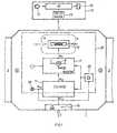
- Figure 1is schematic and in the form of a signal flow / function block diagram a remote control according to the invention represented with a hearing aid, together an inventive Forming hearing aids / remote control kit.
- an inductive remote controlbuilt in. it includes a transmission antenna arrangement 5, preferably formed by a linear preferred ferrite core wound coil.
- the transmit antenna arrangement 5generates a transmission magnetic field H, essentially same as a magnetic dipole P, which is in the direction the bracelet 3, as shown in Fig. 1, is aligned or with an analog clock, in the direction of the six / twelve o'clock timestamps.
- the antenna arrangement 5is with the output A, a transmitter unit 7 operatively connected, which, as shown schematically, one AM or FM modulable transmission oscillator 9 comprises.
- the modulationtakes place at the transmitter oscillator 9 a center frequency f, preferably in the range between 10 kHz and 100 kHz, particularly preferably in the range between 20 kHz and 60 kHz, very particularly preferably in the range between 35 kHz and 45 kHz.
- the transmission oscillator 9can also be frequency-modulated, preferably on two or more fixed predetermined Frequency values.
- the transmitter unit 7is operatively connected to the output A 11 of a control unit 11, which acts as a coding and modulator stage.
- the output A 11 of the control unit 11is operatively connected to the modulation input MOD of the transmission oscillator 9.
- control signals Tare input from the outside, as mentioned, manually or by voice input to the input E 11 of the control unit 11.
- the hearing aid 15 with microphone 17, signal processing unit 19 and output-side electro-mechanical converter 21has a receiver unit 23, matched to the transmitter / antenna arrangement 7, 5 on the wristwatch.
- the receiver unit 23 with decoding unitdecodes the received ones Control commands and guides them in a compatible format the signal processing unit 19 of the hearing aid 15 further.
- the electrically active components of the built-in on the wristwatch Remote controlis provided by a battery or accumulator feed unit 25 electrically powered, the latter preferably comprises a lithium-ion battery.
- the clock-function operating unitis furthermore schematically shown in broken lines 27 shown for the wristwatch.
- the remote control provided according to the invention with the units 5, 7, 11, 13 and 25is preferably independent of the clock function operating unit 27 is provided, if necessary is only the battery and accumulator unit 25 also for the electrical operation of the clock function operating unit 27 used.
- the control unitalso acts with an output A 111 , formed on a display 29 as an acoustic and / or visual display.
- this displaycomprises a visual display, preferably in the form of an LED display.
- the display 29indicates when the control units 11 a control signal from the Has received input unit 13. It will therefore receive one such signals acknowledged with this display 29.
- an advertisementmay alternatively or additionally also with the transmitter unit 7, as shown in dashed lines, be connected, e.g. to acknowledge that a valid Command signal generated and via antenna arrangement 5 to the hearing aid was sent.
- the display 29preferably shows the operating or charging status of the feed unit 25 on.
- FIG. 2the wrist of a person is shown schematically, with bracelet 3 and case 1 of a wristwatch according to the invention integrated remote control.
- Pis the magnetic one Dipole of the coil arrangement 5 shown in FIG. 1.
- the wrist in front of the torso for remote control operationis held on the wristwatch, so is the relative position of the dipole P with respect to the ear OH of the person with a Hearing aid, for example with receiver coil 23 ', as they are 2 shows:
- the transmission field Hoptimally directed towards the ear OH and is there for example with the receiving coil 23 'on an outer ear hearing aid optimally received. This will ensure connection security significantly increased, which is hardly influenced when the Wrist or watch position in the usual range of variation varies, which ensures comfortable viewing of the clock display is.
Landscapes
- Engineering & Computer Science (AREA)
- Physics & Mathematics (AREA)
- Signal Processing (AREA)
- General Health & Medical Sciences (AREA)
- Neurosurgery (AREA)
- Otolaryngology (AREA)
- Computer Networks & Wireless Communication (AREA)
- Acoustics & Sound (AREA)
- Health & Medical Sciences (AREA)
- Electric Clocks (AREA)
- Selective Calling Equipment (AREA)
- Support Of Aerials (AREA)
- Electromechanical Clocks (AREA)
- Details Of Aerials (AREA)
- Transmitters (AREA)
Description
Translated fromGermanDie vorliegende Erfindung betrifft eine Hörgerät-Fernsteuerungnach dem Oberbegriff von Anspruch 1 sowie ein Hörgerät mit einersolchen Fernsteuerung nach demjenigen von Anspruch 8.The present invention relates to a hearing aid remote controlaccording to the preamble of
Induktive Fernsteuerungen für Hörgeräte sind seit langem bekannt,beispielsweise aus der CH-PS 670 349. Sie bilden ein Gerätmehr, welches das Individuum griffbereit halten muss, umnötigenfalls auf den Betrieb seines Hörgerätes einzugreifen.Dabei ist es nicht jedermanns Sache, in der Oeffentlichkeit nötigenfallsdie Fernsteuerung als nicht unauffälliges Gerät hervorzunehmen,und auf sein Hörgerät einzugreifen, wird doch damitkundgetan, dass ein Hörgerät getragen wird, entgegen denBestrebungen, dies möglichst verborgen zu halten.Inductive remote controls for hearing aids have long been knownfor example from CH-PS 670 349. They form a devicemore that the individual must keep within reach tointervene if necessary on the operation of his hearing aid.It is not for everyone, if necessary in publicto take the remote control as a not inconspicuous device,and to intervene on his hearing aid is soannounced that a hearing aid is worn, contrary to theEfforts to keep this hidden as much as possible.
Im weiteren besteht das Problem, die Fernsteuerung gerade dann,wenn sie gebraucht wird, nicht bei der Hand zu haben.Furthermore, there is the problem of remote control,when not needed at hand.
Es ist Aufgabe der vorliegenden Erfindung, die erwähnten Problemezu lösen.It is an object of the present invention to solve the problems mentionedto solve.
Dies wird an der erfindungsgemässen Hörgerät-Fernsteuerung eingangsgenannter Art bei ihrer Ausbildung nach dem Kennzeichenvon Anspruch 1 erreicht.This is mentioned at the hearing aid remote control according to the inventionmentioned type in their training after the license plateachieved by
Demnach wird die induktive Fernsteuerung, welche üblicherweiseeine Sendereinheit aufweist, die ausgangsseitig auf eine Spulenanordnungals Sendeantenne wirkt sowie eine von aussen mitSteuersignalen bedienbare Steuereinheit, die mindestens einenTeil dieser Steuersignale für das Hörgerät, ausgangsseitig, derSendereinheit übermittelt sowie mit einer Akkumulator- oderBatteriespeiseeinheit, mit Sendereinheit, Spulenanordnung,Steuereinheit sowie Akkumulator- oder Batteriespeiseeinheit in eine Armbanduhr eingebaut. Die Spulenanordnung wird dabei soausgelegt, dass sie mindestens genähert ein Magnetfeld erzeugt,gleich wie eine parallel zur Armbandausrichtung an der Uhr angeordnetermagnetischer Dipol.Accordingly, the inductive remote control, which is usuallyhas a transmitter unit on the output side of a coil arrangementacts as a transmitting antenna as well as one from the outsideControl signals operable control unit that has at least onePart of these control signals for the hearing aid, the output side, theTransmitter unit transmitted as well as with an accumulator orBattery supply unit, with transmitter unit, coil arrangement,Control unit and accumulator or battery supply unit ina wristwatch built in. The coil arrangement is sodesigned to generate a magnetic field at least approximated,the same as one placed on the watch parallel to the orientation of the braceletmagnetic dipole.
Bei einer analog anzeigenden Uhr entspricht die erwähnte Ausrichtungder Richtung zwischen der Sechs-/Zwölf-Uhr-Marke.In the case of an analog clock, the orientation mentioned correspondsthe direction between the six and twelve o'clock mark.
Bezüglich der Integration von Fernsteuerungen in eine Armbanduhrkann verwiesen werden auf die US-A 4 063 410, die DE 36 42828, entsprechend der US 4 947 432 sowie auf die EP 0 298 323.Regarding the integration of remote controls in a wristwatchcan be referred to US-A 4 063 410, DE 36 42828, corresponding to US 4 947 432 and to EP 0 298 323.
Es wird mit dem erfindungsgemässen Einbau einer induktiv wirkendenFernsteuerung, d.h. mit einer Spulenanordnung als Sendeantennein eine Armbanduhr und als Hörgerät-Fernsteuerung zusätzlichdas Problem gelöst, dass für die Position einer herkömmlichenFernbedienung, keine Vorschriften gemacht werdenkönnen und die Kommunikationsverbindung Fernsteuerung/Hörgerätaufgrund einer im Bedienungsmoment ungünstigen Relativ-Positionierungoft nicht zustande kommt oder unterbrochen wird.Bei der erfindungsgemässen Fernsteuerung wird mit dem Arm dieArmbanduhr und damit die Fernsteuerung bei ihrer Bedienung innerhalbeines relativ kleinen Positionierungsbereiches, im allgemeinenvor dem Torso der erwähnten Person, positioniert, womitermöglicht ist, die Kommunikationsverbindung weitestgehendsicherzustellen.With the installation according to the invention, there is an inductive effectRemote control, i.e. with a coil arrangement as a transmitting antennain a wristwatch and also as a hearing aid remote controlsolved the problem that for the position of a conventionalRemote control, no regulations are madecan and the communication link remote control / hearing aiddue to an unfavorable relative positioning in the operating momentoften does not come about or is interrupted.In the remote control according to the invention, the armWristwatch and thus the remote control when operating withina relatively small positioning range, in generalpositioned in front of the torso of the person mentioned, with whatthe communication link is largely possiblesure.
Unter Berücksichtigung der Miniaturisierung heutiger Hörgerätesowie dem Bestreben, letztere möglichst unauffällig im Ohrbereichzu verbergen, können mithin Probleme betreffend der Uebertragungssicherheitbei erfindungsgemässem Vorgehen einfachgelöst werden, insbesondere auch berücksichtigend, dass einesolche Fernsteuerung, induktiv wirkend und damit auf der Basis elektromagnetischer Felder, mit derart geringen Leistungenauskommen muss, dass für ihren Betrieb keine Frequenzbandeinschränkungenund Sonderbewilligungen zu gewärtigen bzw. notwendigsind, wie dies bei höheren Leistungen aus der Funkübermittlungstechnikbekannt ist.Taking into account the miniaturization of today's hearing aidsas well as the effort to make the latter as unobtrusive as possible in the ear areato hide, therefore, problems related to transmission securitysimple with the procedure according to the inventionbe resolved, in particular also taking into account that asuch remote control, inductive and therefore basedelectromagnetic fields, with such low powersmust manage that there are no frequency band restrictions for their operationand special permits to be awaited or necessaryare like this with higher services from radio transmission technologyis known.
Im Rahmen der vorliegenden Erfindung wird diese optimale Verbindungssicherheitzwischen Fernsteuerung an der Armbanduhr undHörgerät dann erreicht, wenn, wie erwähnt, die Spulenanordnungein Magnetfeld erzeugt, genähert gleich demjenigen eines magnetischenDipoles an der Armbanduhr, ausgerichtet in der Richtungdes Uhrarmbandes bzw. bei analoger Zeitanzeige an der Uhr, inder Sechs-/Zwölf-Uhr-Richtung.In the context of the present invention, this optimal connection securitybetween remote control on the watch andHearing aid reaches when, as mentioned, the coil arrangementgenerates a magnetic field approximating that of a magnetic oneDipoles on the watch, aligned in that directionof the watch band or with analog time display on the watch, inthe six / twelve o'clock direction.
Obwohl es im weiteren primär naheliegend wäre, Komponenten, wiebeispielsweise hochstabile Referenzoszillatoren, die bereits ander Uhr für die Uhrfunktion vorgesehen sind, auch für die erfindungsgemässeingebaute Fernsteuerung auszunützen, wird ineiner bevorzugten Ausführungsform gemäss Anspruch 2 dieser Ansatzgerade nicht verfolgt. Es wird nämlich dadurch, dass mindestensein Teil der Einheiten, nämlich von Sendereinheit, Spulenanordnung,Steuereinheit und Akkumulator oder Batteriespeiseeinheitals von Betriebseinheiten für die Uhrfunktion unabhängigeEinheiten in der Armbanduhr integriert werden, bevorzugterweisedabei mindestens die Sendereinheit, die Spulenanordnungsowie die Steuereinheit erreicht, dass die erfindungsgemässeIntegration von Fernsteuerung in der Armbanduhr realisierbarwird, ohne wesentliche Aenderungen an bekannten und bereitsin weitem Umfang produzierten Betriebseinheiten für dieUhrfunktion, womit eine wesentlich höhere Flexibilität erreichtwird, die erwähnte Integration an verschiedendst aufgebautenArmbanduhren zu realisieren.Although it would be obvious in the following, components likeFor example, highly stable reference oscillators that are already onthe clock are provided for the clock function, also for those according to the inventionto take advantage of built-in remote controla preferred embodiment according to claim 2, this approachnot being tracked right now. It is because at leastpart of the units, namely transmitter unit, coil arrangement,Control unit and accumulator or battery supply unitas independent of operating units for the clock functionUnits are integrated in the wristwatch, preferablyat least the transmitter unit, the coil arrangementand the control unit achieves that the inventiveIntegration of remote control in the wristwatch possibleis, without significant changes to known and alreadyoperating units for theClock function, which achieves a much higher flexibilitythe mentioned integration on variously builtTo realize wristwatches.
In einer weiteren bevorzugten Ausführungsform der erfindungsgemässenFernsteuerung wird, dem Wortlaut von Anspruch 4 folgend,an der Armbanduhr mindestens ein manuell betätigbares Eingabeorganvorgesehen für die Bedienung der Steuereinheit, vorzugsweisemehr als eines, womit nebst Betriebsmodusumschaltungen,In a further preferred embodiment of the inventiveRemote control is, according to the wording of claim 4,on the wristwatch at least one manually operable input deviceprovided for the operation of the control unit, preferablymore than one, which, in addition to operating mode switches,
Steuerbefehle, wie für Lautheit, Richtcharakteristik, Frequenz-Filterungsverhalten,etc. am Hörgerät angesteuert werden.Selbstverständlich ist es durchaus möglich, anstelle einem oderzusätzlich zu mehreren manuell bedienbaren Eingabeorganen, wieTastern, kapazitiven Berührungssensoren etc. an der Armbanduhrdie Bedienungssignale durch Spracheingabe einzugeben.Control commands, such as for loudness, directional characteristic, frequency filtering behavior,etc. on the hearing aid.Of course it is quite possible, instead of an orin addition to several manually operated input elements, such asButtons, capacitive touch sensors etc. on the wristwatchenter the operating signals by voice input.
In einer weiteren bevorzugten Ausführungsform der erfindungsgemässenFernsteuerung ist, dem Wortlaut von Anspruch 4 folgend,an der Uhr eine visuelle und/oder akustische Anzeige vorgesehen,vorzugsweise eine LED-Anzeige umfassend, welche mit derSteuereinheit und/oder der Sendereinheit wirkverbunden ist, undwelche bevorzugterweise mindestens die ordnungsgemässe Bedienungvon aussen der von aussen bedienbaren Steuereinheit quittiert,und/oder Erreichen eines vorgebbaren Ladezustandes derBatterie oder Akkumulatoreinheit der Fernsteuerung anzeigt. Damitwird erreicht, dass die Bedienungsperson einerseits Sicherheitdarüber hat, dass eingegebene Befehlssignale richtig registriertwurden, was insbesondere bei Tasten und/oder Spracheingabewesentlich ist bzw. wird darüber orientiert, wann ein Batteriewechselbzw. eine Aufladung des Akkumulators notwendigist.In a further preferred embodiment of the inventiveRemote control is, according to the wording of claim 4,a visual and / or acoustic display is provided on the watch,preferably comprising an LED display, which with theControl unit and / or the transmitter unit is operatively connected, andwhich preferably at least proper operationacknowledged from outside the control unit that can be operated from outside,and / or reaching a predefinable state of charge of theRemote control battery or accumulator unit. In order toit is achieved that the operator safety on the one handabout that has correctly entered command signals registeredwere what especially with buttons and / or voice inputit is essential or is based on when a battery changeor a charging of the accumulator is necessaryis.
In einer weiteren bevorzugten Ausführungsform der erfindungsgemässenFernsteuerung erzeugt die Sendereinheit ein Amplitudenmodulierbares(AM)- oder Frequenz-modulierbares (FM)-Signal mit einer Mittenfrequenz f innerhalb eines Frequenzbereiches, wofürgilt
Obwohl es durchaus möglich ist, das erfindungsgemäss eingesetzteSendefeld, wie spezifiziert wurde, durch Ueberlagerung derFelder mehrerer Spulen zu erzeugen, wird in einer bevorzugtenAusführungsform vorgeschlagen, dem Wortlaut von Anspruch 6 folgend,dass die Spulenanordnung durch eine lineare Spule gebildetist, vorzugsweise durch eine Ferritkern-gewickelte Spule,die dann selbst mit einer Achsausrichtung an der Uhr eingebautist, parallel zur Armbandrichtung bzw. parallel zur Sechs/Zwölf-Uhr-Analoganzeigerichtung.Although it is entirely possible, the one used according to the inventionTransmission field, as specified, by overlaying theGenerating fields of multiple coils is preferredEmbodiment proposed, following the wording of
Weiter wird in einer bevorzugten Ausführungsform gemäss Wortlautvon Anspruch 7 mindestens die Batterie oder Akkumulatoreinheitder Fernsteuerung als Lithium-Ionenbatterieeinheitaufgebaut, gegebenenfalls wird diese Einheit auch für den Betriebder Uhrfunktions-Betriebseinheit eingesetzt.In a preferred embodiment, according to the wordingof claim 7 at least the battery or accumulator unitthe remote control as a lithium-ion battery unitset up, this unit may also be used for operationthe clock function operating unit.
Ein erfindungsgemässer Satz mindestens eines Hörgerätes mit einererfindungsgemässen Fernsteuerung zeichnet sich, dem Wortlautvon Anspruch 8 folgend, dadurch aus, dass die Fernsteuerung,wie vorbeschrieben wurde, aufgebaut ist, und an mindestens einem Hörgerät eine auf die Sendereinheit der Fernsteuerungabgestimmte Empfängereinheit vorgesehen ist.A set according to the invention of at least one hearing aid with oneRemote control according to the invention stands out, the wordingfrom claim 8, characterized in that the remote control,as described above, is structured, and at leasta hearing aid on the transmitter unit of the remote controlcoordinated receiver unit is provided.
Die Erfindung wird anschliessend beispielsweise anhand von Figurenerläutert.The invention is then illustrated, for example, with the aid of figuresexplained.
Es zeigen:
- Fig. 1
- schematisch vereinfacht, in Form eines Signalfluss/Funktionsblock-Diagrammes,die erfindungsgemässeFernsteuerung sowie ein damit ansteuerbares Hörgerät,gemeinsam einen erfindungsgemässen Satz Hörgerät/Fernsteuerungdarstellend,
- Fig. 2
- schematisch die Kommunikationsfeld-Verbindung einer erfindungsgemässenFernsteuerung und eines Hörgerätes insitu.
- Fig. 1
- schematically simplified, in the form of a signal flow / function block diagram, the remote control according to the invention and a hearing device which can be controlled thereby, together representing a set of hearing device / remote control according to the invention,
- Fig. 2
- schematically the communication field connection of a remote control according to the invention and a hearing aid in situ.
In Figur 1 ist schematisch und in Form eines Signalfluss/Funktionsblock-Diagrammeseine erfindungsgemässe Fernsteuerungdargestellt mit einem Hörgerät, gemeinsam einen erfindungsgemässenHörgeräte/Fernbedienungs-Satz bildend.In Figure 1 is schematic and in the form of a signal flow / function block diagrama remote control according to the inventionrepresented with a hearing aid, together an inventiveForming hearing aids / remote control kit.
In einem Gehäuse 1 einer Armbanduhr mit Armband 3 ist erfindungsgemässeine induktive Fernsteuerung eingebaut. Sie umfassteine Sendeantennenanordnung 5, bevorzugterweise gebildet durcheine lineare bevorzugte Ferritkern-gewickelte Spule. Die Sendeantennenanordnung5 erzeugt ein Sendemagnetfeld H, im wesentlichengleich wie ein magnetischer Dipol P, welcher in Richtungdes Armbandes 3, wie in Fig. 1 dargestellt, ausgerichtet istbzw. bei einer analog anzeigenden Uhr, in Richtung der Sechs/Zwölf-Uhr-Zeitmarken.In a
Die Antennenanordnung 5 ist mit dem Ausgang A, einer Sendereinheit7 wirkverbunden, welche, wie schematisch dargestellt, einenAM- oder FM-modulierbaren Sendeoszillator 9 umfasst. Bevorzugterweiseerfolgt die Modulation am Sender-Oszillator 9 miteiner Mittenfrequenz f, bevorzugterweise im Bereich zwischen 10kHz und 100 kHz, insbesondere bevorzugt im Bereich zwischen 20kHz und 60 kHz, ganz besonders bevorzugt im Bereich zwischen 35kHz und 45 kHz. Weiter bevorzugt ist der Sendeoszillator 9 frequenzmodulierbar,bevorzugterweise auf zwei oder mehr fix vorgegebenenFrequenzwerten.The antenna arrangement 5 is with the output A, a transmitter unit7 operatively connected, which, as shown schematically, oneAM or FM
Eingangsseitig ist die Sendereinheit 7 mit dem Ausgang A11 einerSteuereinheit 11 wirkverbunden, welche als Codier- und Modulatorstufewirkt. Der Ausgang A11 der Steuereinheit 11 istdabei mit dem Modulationseingang MOD des Sendeoszillators 9wirkverbunden. An einer Eingabeeinheit 13, umfassend eine odermehrere von aussen manuell bedienbare Eingabeorgane, wie z.B.Tasten und/oder ein Eingabemikrophon für Spracheingabe, werdenSteuersignale T von aussen, wie erwähnt manuell oder durchSpracheingabe an den Eingang E11 der Steuereinheit 11 eingegeben.Diese codiert die eingegebenen Steuersignale und erzeugtausgangsseitig entsprechende Modulationssignale für die Sendereinheit7, welche ausgangsseitig über die Antennenanordnung 5,die entsprechenden Steuerbefehle an ein Hörgerät 15 übermittelt.Das Hörgerät 15 mit Mikrophon 17, Signalverarbeitungseinheit19 und ausgangsseitigem elektro-mechanischem Wandler 21weist eine Empfängereinheit 23 auf, abgestimmt auf Sender/Antennen-Anordnung7, 5 an der Armbanduhr.On the input side, the transmitter unit 7 is operatively connected to the output A11 of a
Die Empfängereinheit 23 mit Decodiereinheit decodiert die empfangenenSteuerbefehle und leitet sie in kompatiblem Format andie Signalverarbeitungseinheit 19 des Hörgerätes 15 weiter.The
Die elektrisch aktiven Baueinheiten der an der Armbanduhr eingebautenFernsteuerung werden durch eine Batterie bzw. Akkumulator-Speiseeinheit25 elektrisch gespiesen, welch letztere bevorzugterweiseeine Lithium-Ionenbatterie umfasst.The electrically active components of the built-in on the wristwatchRemote control is provided by a battery or
In Fig. 1 ist weiter strichpunktiert schematisch die Uhr-Funktions-Betriebseinheit27 für die Armbanduhr dargestellt.Die erfindungsgemäss vorgesehene Fernsteuerung mit den Einheiten5, 7, 11, 13 und 25 wird bevorzugterweise unabhängig vonder Uhrfunktions-Betriebseinheit 27 vorgesehen, gegebenenfallswird lediglich die Batterie und Akkumulatoreinheit 25 auch fürden elektrischen Betrieb der Uhrfunktions-Betriebseinheit 27eingesetzt.In Fig. 1, the clock-function operating unit is furthermore schematically shown in
Die Steuereinheit wirkt weiter mit einem Ausgang A111, auf eineAnzeige 29 als akustische und/oder optische Anzeige ausgebildet.The control unit also acts with an output A111 , formed on a
In bevorzugter Ausführungsform und wie in Fig. 1 dargestellt,umfasst diese Anzeige eine optische Anzeige, bevorzugterweisein Form einer LED-Anzeige.In a preferred embodiment and as shown in Fig. 1,this display comprises a visual display, preferablyin the form of an LED display.
Insbesondere wird mit der Anzeige 29 angezeigt, wenn die Steuereinheiten11 ein als gültig erkanntes Steuersignal von derEingabeeinheit 13 erhalten hat. Es wird mithin Erhalt einessolchen Signales mit dieser Anzeige 29 quittiert. Selbstverständlichkann eine solche Anzeige alternativ oder ergänzendauch mit der Sendereinheit 7, wie gestrichelt dargestellt,wirkverbunden sein, um z.B. zu quittieren, dass ein gültigesBefehlssignal erzeugt und via Antennenanordnung 5 an das Hörgerätgesendet wurde. Im weiteren zeigt die Anzeige 29 bevorzugterweiseden Betriebs- bzw. Ladezustand der Speiseeinheit 25an.In particular, the
In Figur 2 ist schematisch das Handgelenk einer Person dargestellt,mit Armband 3 und Gehäuse 1 einer Armbanduhr mit erfindungsgemässintegrierter Fernsteuerung. Mit P ist der magnetischeDipol der Spulenanordnung 5 gemäss Fig. 1 dargestellt.Wenn das Handgelenk vor dem Torso für die Bedienung der Fernsteuerungan der Armbanduhr gehalten wird, so ist die Relativpositiondes Dipols P bezüglich des Ohres OH der Person mit einemHörgerät, beispielsweise mit Empfängerspule 23', so wie siein Fig. 2 dargestellt ist: Bei der erfindungsgemässen Positionierungdes magnetischen Sendedipols P an der Uhr ist das SendefeldH optimal bezüglich des Ohres OH gerichtet und wird dortbeispielsweise mit der Empfangsspule 23' an einem Aussenohr-Hörgerätoptimal empfangen. Dadurch wird die Verbindungssicherheitmassgeblich erhöht, die kaum beeinflusst wird, wenn dieHandgelenk- bzw. die Uhr-Position im üblichen Variationsbereichvariiert, worin bequeme Betrachtung der Uhranzeige sichergestelltist.In Figure 2, the wrist of a person is shown schematically,with
Claims (8)
- Hearing device remote control with a transmitterunit, which acts on the output side on a coilarrangement as a transmitting antenna, as well aswith a control unit, which can be externallyoperated by control signals and transmits at leastsome of these control signals for the hearingdevice, on the output side, to the transmitterunit, and also with a rechargeable-battery- orbattery-power-supply-unit,characterized in thatthe transmitter unit, the coil arrangement, thecontrol unit and the rechargeable-battery- orbattery-power-supply-unit are fitted in awristwatch and the coil arrangement generates atleast approximately a magnetic field like amagnetic dipole arranged parallel to the alignmentof the strap on the watch.
- Remote control according to Claim 1,characterizedin that at least some of the units comprising thetransmitter unit, coil arrangement, control unitand rechargeable-battery- or battery-power-supply-unitare integrated in the wristwatch as units thatare independent of the operating units for thefunction of the watch, preferably at least thetransmitter unit, the coil arrangement and thecontrol unit.
- Remote control according to one of Claims 1 or 2,characterized in that the wristwatch comprises atleast one manually operable input element foroperating the control unit, preferably more thanone.
- Remote control according to one of Claims 1 to 3,characterized in that a visual and/or acousticindication is provided on the watch, preferablycomprising an LED display, which is operativelyconnected to the control unit and/or thetransmitter unit, and which preferably acknowledgesat least the proper external operation of theexternally operable control unit, and/or indicatesthe reaching of a predeterminable charging state ofthe battery or rechargeable-battery-unit.
- Remote control according to one of Claims 1 to 4,characterized in that the transmitter unit emits anAM or FM signal, with a mid-frequency f within afrequency range for which the following applies:
- Remote control according to one of Claims 1 to 5,characterized in that the coil arrangement isformed by a linear coil, preferably by a ferritecore-woundcoil.
- Remote control according to one of Claims 1 to 6,characterized in that at least the battery- or rechargeable-battery-unit of the remote control isconstructed as a lithium-ion battery unit.
- Hearing device with remote control,characterizedin that the remote control is constructed according toone of Claims 1 to 7, andin that the at least onehearing device has a receiver unit tuned to thetransmitter unit of the remote control.
Applications Claiming Priority (1)
| Application Number | Priority Date | Filing Date | Title |
|---|---|---|---|
| PCT/CH2000/000020WO2000038495A2 (en) | 2000-01-13 | 2000-01-13 | Hearing aid remote control and a hearing aid with a remote control of this type |
Publications (2)
| Publication Number | Publication Date |
|---|---|
| EP1247423A2 EP1247423A2 (en) | 2002-10-09 |
| EP1247423B1true EP1247423B1 (en) | 2003-07-23 |
Family
ID=4358029
Family Applications (1)
| Application Number | Title | Priority Date | Filing Date |
|---|---|---|---|
| EP00900199AExpired - LifetimeEP1247423B1 (en) | 2000-01-13 | 2000-01-13 | Hearing aid remote control and a hearing aid with a remote control of this type |
Country Status (8)
| Country | Link |
|---|---|
| US (1) | US6816600B1 (en) |
| EP (1) | EP1247423B1 (en) |
| JP (1) | JP4388703B2 (en) |
| AU (1) | AU775802B2 (en) |
| CA (1) | CA2397317C (en) |
| DE (1) | DE50003048D1 (en) |
| DK (1) | DK1247423T3 (en) |
| WO (1) | WO2000038495A2 (en) |
Cited By (1)
| Publication number | Priority date | Publication date | Assignee | Title |
|---|---|---|---|---|
| DE102004025123A1 (en)* | 2004-05-21 | 2005-07-21 | Siemens Audiologische Technik Gmbh | Hearing aid with acoustic battery status display whereby the current charge level of the battery is determined and communicated to the user by an acoustic signal |
Families Citing this family (27)
| Publication number | Priority date | Publication date | Assignee | Title |
|---|---|---|---|---|
| US7356153B2 (en)* | 2002-05-28 | 2008-04-08 | Blumenau Trevor I | Hearing assistive apparatus having sound replay capability |
| US7336796B2 (en)* | 2002-05-28 | 2008-02-26 | Blumenau Trevor I | Hearing assistive apparatus having sound replay capability and spatially separated components |
| US6839446B2 (en)* | 2002-05-28 | 2005-01-04 | Trevor I. Blumenau | Hearing aid with sound replay capability |
| DE10305830B3 (en)* | 2003-02-12 | 2004-10-21 | Siemens Audiologische Technik Gmbh | Device and method for remote control of a hearing aid |
| US20070009123A1 (en)* | 2003-04-30 | 2007-01-11 | Stefan Aschoff | Remote control unit for a hearing aid |
| US7256747B2 (en)* | 2004-01-30 | 2007-08-14 | Starkey Laboratories, Inc. | Method and apparatus for a wireless hearing aid antenna |
| EP1624723B1 (en)* | 2004-08-02 | 2012-05-30 | Siemens Audiologische Technik GmbH | Stabilisation of the system-clock pulse in a hearing aid |
| DE102005010625A1 (en) | 2005-03-08 | 2006-09-14 | Phonak Ag | Remote control for a hearing aid |
| US8358785B2 (en) | 2006-05-30 | 2013-01-22 | Siemens Audiologische Technik Gmbh | Hearing system with wideband pulse transmitter |
| DE102006025147B3 (en)* | 2006-05-30 | 2007-10-25 | Siemens Audiologische Technik Gmbh | Hearing system for use in e.g. museum, has hearing devices provided with transceiver, which includes digital broadband pulse transmitter, where bandwidth of pulse transmitter amounts to hundred megahertz |
| US8081787B2 (en)* | 2006-12-20 | 2011-12-20 | Phonak Ag | Hearing assistance system and method of operating the same |
| DK2117180T3 (en) | 2008-05-07 | 2014-02-03 | Oticon As | A short-range wireless one-way connection |
| JP5256119B2 (en)* | 2008-05-27 | 2013-08-07 | パナソニック株式会社 | Hearing aid, hearing aid processing method and integrated circuit used for hearing aid |
| US8155340B2 (en) | 2008-07-24 | 2012-04-10 | Qualcomm Incorporated | Method and apparatus for rendering ambient signals |
| US7929722B2 (en)* | 2008-08-13 | 2011-04-19 | Intelligent Systems Incorporated | Hearing assistance using an external coprocessor |
| KR101007138B1 (en)* | 2008-10-01 | 2011-01-10 | (주)알고코리아 | Wirelessly controlled whisper digital hearing aid |
| US9247356B2 (en) | 2013-08-02 | 2016-01-26 | Starkey Laboratories, Inc. | Music player watch with hearing aid remote control |
| US10009069B2 (en) | 2014-05-05 | 2018-06-26 | Nxp B.V. | Wireless power delivery and data link |
| US10015604B2 (en) | 2014-05-05 | 2018-07-03 | Nxp B.V. | Electromagnetic induction field communication |
| US9812788B2 (en) | 2014-11-24 | 2017-11-07 | Nxp B.V. | Electromagnetic field induction for inter-body and transverse body communication |
| US9819075B2 (en)* | 2014-05-05 | 2017-11-14 | Nxp B.V. | Body communication antenna |
| US9819395B2 (en)* | 2014-05-05 | 2017-11-14 | Nxp B.V. | Apparatus and method for wireless body communication |
| US10014578B2 (en)* | 2014-05-05 | 2018-07-03 | Nxp B.V. | Body antenna system |
| US9819097B2 (en) | 2015-08-26 | 2017-11-14 | Nxp B.V. | Antenna system |
| US10320086B2 (en) | 2016-05-04 | 2019-06-11 | Nxp B.V. | Near-field electromagnetic induction (NFEMI) antenna |
| CN111295895B (en) | 2017-10-23 | 2021-10-15 | 科利耳有限公司 | Body-worn device, multi-purpose device and method |
| EP3701729A4 (en) | 2017-10-23 | 2021-12-22 | Cochlear Limited | EXTENDED SUPPORT FOR DENTURE-ASSISTED COMMUNICATION |
Family Cites Families (14)
| Publication number | Priority date | Publication date | Assignee | Title |
|---|---|---|---|---|
| DE2944748A1 (en)* | 1979-11-06 | 1981-05-07 | Fa. A. Raymond, 7850 Lörrach | HOLDING CLIP FOR DETACHABLE FASTENING OF FUNCTIONAL ELEMENTS ON A CARRIER PLATE BY THREADED BOLTS |
| DE3642828C3 (en)* | 1986-02-03 | 1995-05-04 | Toepholm & Westermann | Remote controllable hearing aid |
| US4947432B1 (en)* | 1986-02-03 | 1993-03-09 | Programmable hearing aid | |
| EP0298323A1 (en)* | 1987-07-07 | 1989-01-11 | Siemens Aktiengesellschaft | Hearing aid apparatus |
| CH672870B5 (en)* | 1988-04-26 | 1990-07-13 | Ebauchesfabrik Eta Ag | |
| DE8815967U1 (en)* | 1988-05-27 | 1989-09-21 | Junghans Uhren GmbH, 7230 Schramberg | Antenna for a small radio clock |
| DE9000899U1 (en)* | 1990-01-27 | 1991-05-23 | Junghans Uhren Gmbh, 78713 Schramberg | Autonomous radio clock |
| DE4109840A1 (en)* | 1991-03-26 | 1992-10-01 | Bosch Gmbh Robert | Reception antenna for long wave transmissions - has coil wound around amorphous soft magnetic alloy core |
| US5578999A (en)* | 1993-12-06 | 1996-11-26 | Casio Computer Co., Ltd. | Remote control with learning function and confirmation thereof |
| US5721783A (en)* | 1995-06-07 | 1998-02-24 | Anderson; James C. | Hearing aid with wireless remote processor |
| US5824022A (en)* | 1996-03-07 | 1998-10-20 | Advanced Bionics Corporation | Cochlear stimulation system employing behind-the-ear speech processor with remote control |
| FR2748360B1 (en)* | 1996-05-03 | 1998-06-26 | Ebauchesfabrik Eta Ag | DEVICE FOR RECEIVING AND / OR TRANSMITTING PORTABLE RADIO-BROADCAST MESSAGES COMPRISING AN INDUCTIVE AND CAPACITIVE ANTENNA |
| CH690525A5 (en)* | 1996-11-22 | 2000-09-29 | Ebauchesfabrik Eta Ag | Timepiece including a receiving antenna and / or transmitting a radio broadcast signal. |
| DE19926271C2 (en)* | 1999-06-09 | 2002-09-26 | Junghans Uhren Gmbh | Funkarmbanduhr |
- 2000
- 2000-01-13EPEP00900199Apatent/EP1247423B1/ennot_activeExpired - Lifetime
- 2000-01-13DEDE50003048Tpatent/DE50003048D1/ennot_activeExpired - Lifetime
- 2000-01-13AUAU19609/00Apatent/AU775802B2/ennot_activeCeased
- 2000-01-13DKDK00900199Tpatent/DK1247423T3/enactive
- 2000-01-13USUS09/482,366patent/US6816600B1/ennot_activeExpired - Fee Related
- 2000-01-13JPJP2000590461Apatent/JP4388703B2/ennot_activeExpired - Lifetime
- 2000-01-13WOPCT/CH2000/000020patent/WO2000038495A2/enactiveIP Right Grant
- 2000-01-13CACA002397317Apatent/CA2397317C/ennot_activeExpired - Fee Related
Cited By (2)
| Publication number | Priority date | Publication date | Assignee | Title |
|---|---|---|---|---|
| DE102004025123A1 (en)* | 2004-05-21 | 2005-07-21 | Siemens Audiologische Technik Gmbh | Hearing aid with acoustic battery status display whereby the current charge level of the battery is determined and communicated to the user by an acoustic signal |
| US7577267B2 (en) | 2004-05-21 | 2009-08-18 | Siemens Audiologische Technik Gmbh | Hearing aid and hearing aid system |
Also Published As
| Publication number | Publication date |
|---|---|
| JP4388703B2 (en) | 2009-12-24 |
| DK1247423T3 (en) | 2003-11-03 |
| WO2000038495A2 (en) | 2000-07-06 |
| CA2397317C (en) | 2009-04-14 |
| DE50003048D1 (en) | 2003-08-28 |
| CA2397317A1 (en) | 2000-07-06 |
| JP2003511876A (en) | 2003-03-25 |
| EP1247423A2 (en) | 2002-10-09 |
| AU1960900A (en) | 2000-07-31 |
| AU775802B2 (en) | 2004-08-19 |
| WO2000038495A3 (en) | 2001-04-12 |
| US6816600B1 (en) | 2004-11-09 |
Similar Documents
| Publication | Publication Date | Title |
|---|---|---|
| EP1247423B1 (en) | Hearing aid remote control and a hearing aid with a remote control of this type | |
| EP0175909B1 (en) | Hearing aid device | |
| DE69926810T2 (en) | SYSTEM OF AUTOMATIC TIME SETTING OF A PORTABLE OBJECT WITH A CLOCK FUNCTION | |
| DE102008047577B3 (en) | Right-left detection in hearing aids | |
| EP0298323A1 (en) | Hearing aid apparatus | |
| EP0088154A1 (en) | Speech stimulating device | |
| DE102007046694A1 (en) | Sensor system for measuring, transmitting, processing and displaying a brain parameter | |
| DE69900861T2 (en) | EMERGENCY CALL OR DIAGNOSTIC DEVICE | |
| EP3269423A1 (en) | Implantable medical device with antenna for wireless communication | |
| US7433480B2 (en) | Hearing aid with wireless transmission system, and operating method therefor | |
| EP2249584A2 (en) | Assembly and method for wireless data transmission between hearing aids | |
| EP2012509B1 (en) | Multicomponent hearing aid system and a method for its operation | |
| AT393329B (en) | WAKE-UP DEVICE TO BE WEARED IN THE EAR CHANNEL | |
| DE69901913T2 (en) | TRANSPONDER NEWS SYSTEM | |
| EP1575335B1 (en) | Transmitting system for transmitting signals to a hearing aid and corresponding method | |
| EP1865747B1 (en) | Audio system with inductive transmission and broadband transmission | |
| DE3324957A1 (en) | Method for supplying a portable slave station of a data transmission system with power | |
| DE102004037377B3 (en) | hearing aid | |
| EP0828404B1 (en) | Hearing aid and control device for programming the hearing aid | |
| DE102006032085A1 (en) | Portable electronic unit | |
| DE102021200195B4 (en) | hearing aid | |
| WO1989005559A1 (en) | Electroacoustic transducer | |
| EP1741050B1 (en) | Transponder | |
| EP3863304B1 (en) | Hearing device with inductively coupled antenna unit | |
| CH689075A5 (en) | Electronic and digital transceiver for locating compatible partner |
Legal Events
| Date | Code | Title | Description |
|---|---|---|---|
| PUAI | Public reference made under article 153(3) epc to a published international application that has entered the european phase | Free format text:ORIGINAL CODE: 0009012 | |
| 17P | Request for examination filed | Effective date:20020502 | |
| AK | Designated contracting states | Kind code of ref document:A2 Designated state(s):AT BE CH CY DE DK ES FI FR GB GR IE IT LI LU MC NL PT SE | |
| GRAH | Despatch of communication of intention to grant a patent | Free format text:ORIGINAL CODE: EPIDOS IGRA | |
| GRAH | Despatch of communication of intention to grant a patent | Free format text:ORIGINAL CODE: EPIDOS IGRA | |
| GRAA | (expected) grant | Free format text:ORIGINAL CODE: 0009210 | |
| AK | Designated contracting states | Designated state(s):CH DE DK FR GB IT LI | |
| REG | Reference to a national code | Ref country code:GB Ref legal event code:FG4D Free format text:NOT ENGLISH | |
| REG | Reference to a national code | Ref country code:CH Ref legal event code:EP Ref country code:CH Ref legal event code:NV Representative=s name:TROESCH SCHEIDEGGER WERNER AG | |
| REG | Reference to a national code | Ref country code:IE Ref legal event code:FG4D Free format text:GERMAN | |
| REF | Corresponds to: | Ref document number:50003048 Country of ref document:DE Date of ref document:20030828 Kind code of ref document:P | |
| REG | Reference to a national code | Ref country code:DK Ref legal event code:T3 | |
| GBT | Gb: translation of ep patent filed (gb section 77(6)(a)/1977) | Effective date:20031117 | |
| REG | Reference to a national code | Ref country code:IE Ref legal event code:FD4D | |
| ET | Fr: translation filed | ||
| PLBE | No opposition filed within time limit | Free format text:ORIGINAL CODE: 0009261 | |
| STAA | Information on the status of an ep patent application or granted ep patent | Free format text:STATUS: NO OPPOSITION FILED WITHIN TIME LIMIT | |
| 26N | No opposition filed | Effective date:20040426 | |
| PG25 | Lapsed in a contracting state [announced via postgrant information from national office to epo] | Ref country code:IT Free format text:LAPSE BECAUSE OF NON-PAYMENT OF DUE FEES Effective date:20050113 | |
| PGFP | Annual fee paid to national office [announced via postgrant information from national office to epo] | Ref country code:FR Payment date:20120202 Year of fee payment:13 Ref country code:CH Payment date:20120112 Year of fee payment:13 | |
| PGFP | Annual fee paid to national office [announced via postgrant information from national office to epo] | Ref country code:DE Payment date:20120111 Year of fee payment:13 | |
| PGFP | Annual fee paid to national office [announced via postgrant information from national office to epo] | Ref country code:GB Payment date:20120111 Year of fee payment:13 Ref country code:DK Payment date:20120111 Year of fee payment:13 | |
| REG | Reference to a national code | Ref country code:DK Ref legal event code:EBP | |
| REG | Reference to a national code | Ref country code:CH Ref legal event code:PL | |
| GBPC | Gb: european patent ceased through non-payment of renewal fee | Effective date:20130113 | |
| REG | Reference to a national code | Ref country code:FR Ref legal event code:ST Effective date:20130930 | |
| PG25 | Lapsed in a contracting state [announced via postgrant information from national office to epo] | Ref country code:CH Free format text:LAPSE BECAUSE OF NON-PAYMENT OF DUE FEES Effective date:20130131 Ref country code:LI Free format text:LAPSE BECAUSE OF NON-PAYMENT OF DUE FEES Effective date:20130131 Ref country code:DE Free format text:LAPSE BECAUSE OF NON-PAYMENT OF DUE FEES Effective date:20130801 | |
| REG | Reference to a national code | Ref country code:DE Ref legal event code:R119 Ref document number:50003048 Country of ref document:DE Effective date:20130801 | |
| PG25 | Lapsed in a contracting state [announced via postgrant information from national office to epo] | Ref country code:GB Free format text:LAPSE BECAUSE OF NON-PAYMENT OF DUE FEES Effective date:20130113 Ref country code:FR Free format text:LAPSE BECAUSE OF NON-PAYMENT OF DUE FEES Effective date:20130131 | |
| PG25 | Lapsed in a contracting state [announced via postgrant information from national office to epo] | Ref country code:DK Free format text:LAPSE BECAUSE OF NON-PAYMENT OF DUE FEES Effective date:20130131 |