EP1246304A2 - Coaxial connector - Google Patents
Coaxial connectorDownload PDFInfo
- Publication number
- EP1246304A2 EP1246304A2EP02005377AEP02005377AEP1246304A2EP 1246304 A2EP1246304 A2EP 1246304A2EP 02005377 AEP02005377 AEP 02005377AEP 02005377 AEP02005377 AEP 02005377AEP 1246304 A2EP1246304 A2EP 1246304A2
- Authority
- EP
- European Patent Office
- Prior art keywords
- contact
- insulator
- housing
- part according
- external contact
- Prior art date
- Legal status (The legal status is an assumption and is not a legal conclusion. Google has not performed a legal analysis and makes no representation as to the accuracy of the status listed.)
- Granted
Links
Images

Classifications
- H—ELECTRICITY
- H01—ELECTRIC ELEMENTS
- H01R—ELECTRICALLY-CONDUCTIVE CONNECTIONS; STRUCTURAL ASSOCIATIONS OF A PLURALITY OF MUTUALLY-INSULATED ELECTRICAL CONNECTING ELEMENTS; COUPLING DEVICES; CURRENT COLLECTORS
- H01R13/00—Details of coupling devices of the kinds covered by groups H01R12/70 or H01R24/00 - H01R33/00
- H01R13/62—Means for facilitating engagement or disengagement of coupling parts or for holding them in engagement
- H01R13/629—Additional means for facilitating engagement or disengagement of coupling parts, e.g. aligning or guiding means, levers, gas pressure electrical locking indicators, manufacturing tolerances
- H01R13/631—Additional means for facilitating engagement or disengagement of coupling parts, e.g. aligning or guiding means, levers, gas pressure electrical locking indicators, manufacturing tolerances for engagement only
- H01R13/6315—Additional means for facilitating engagement or disengagement of coupling parts, e.g. aligning or guiding means, levers, gas pressure electrical locking indicators, manufacturing tolerances for engagement only allowing relative movement between coupling parts, e.g. floating connection
Definitions
- the inventionrelates to a coaxial connector part with a housing, a Internal contact, an external contact and an insulator, which is between the Internal contact and the external contact is arranged.
- an adapterwhich is used to connect two Printed circuit boards are used, particularly in the field of high-frequency technology.
- a base partwhich has a ball head is provided.
- an isolatoris pivotally attached, which with an inner conductor and an outer conductor is provided.
- the insulatorcan be in one Complementary base part to be inserted on the other circuit board is appropriate. Due to the pivotable arrangement of the insulator, a lateral offset between the two circuit boards can be compensated. By inserting the insulator into the complementary base part at different depths can compensate for differences in distance between the two circuit boards become.
- the known adapteris not a Plug part, but a coaxial connection, which is used for permanent connection serves between two circuit boards in a circuit board stack. That too is Construction costs comparatively high, since the contacting of the inner conductor and the Outer conductor in the articulated attachment of the insulator is very expensive.
- the object of the inventionis to provide a coaxial connector part mentioned type to the extent that the contacts at low Construction work to be exposed to lower loads if the connector part with misalignment is inserted into a complementary connector part.
- the inventionprovides that the external contact on Housing is pivotally attached, which also means that in the external contact recorded insulator and the internal contact recorded in the insulator as Unit are pivotable.
- the internal contact, External contact and isolator existing contact unit when inserting the complementary connector automatically according to the misalignmentalign the two connector parts so that the central axes of the nested ones Contacts collapse again. The contacts of the two Plug parts can then be easily pushed into one another without excessive loads occur.
- the internal contactis provided with a ball head onto which a spring clip is slid, which can be connected to a printed circuit board using SMT technology.
- a ball headresults in a ball joint-like connection between the internal contact and the spring clip, so that the Contact unit can be adjusted relative to the spring clip without a Motion is transmitted to the spring clip. This ensures that the SMT solder joint, by means of which the spring clip is connected to the circuit board can be exposed to no stress.
- the contribution of ball joint-like connection between the internal contact and the Spring clip for pivoting attachment of the contact unitis negligible.
- the ball head approximately with the pivot point of the Contact unit in the housingcoincides. This ensures that there is none translational movement between spring clip and internal contact comes, if the unit of internal contact, external contact and insulator relative to Housing is pivoted, but it only rotates by a few Angular degrees is coming.
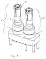
- a coaxial connector partis shown as the most important Components contain a housing 10 and two contact units 12, 14, which on Housing 10 are attached. Each contact unit is made up of one External contact 16, an internal contact 18 and an insulator 20.
- the housing 10consists of an electrically insulating material, for example Plastic, and has two openings for receiving the contact units on.
- a holding ring 11is assigned to the openings, its function will be explained later.
- the external contact 16consists of an electrically conductive material and has a sleeve-shaped apron 22 at its end associated with the housing 10 on, which is provided with two recesses 24.
- the free end of the apron 22is with a circumferential, interrupted by the two recesses 24 Provide projection so that the free end forms two locking hooks 25.
- a shoulder 23intended at the The transition of the apron 22 into the body of the external contact 16 is a shoulder 23 intended.
- the insulator 20is made of an electrically insulating material and has two opposite noses 28 provided, the dimensions so are designed so that they in the recesses 24 of the external contact 16th can be inserted.
- the inner contact 18is made of an electrically conductive material and is here designed as a sleeve, one end slotted and the other end with a ball head 30 is provided.
- the inner contact 18is also with a Snap collar 32 provided.
- the inner contact 18is assigned a spring clip 34 which is U-shaped Has shape.
- the two opposite legs of the spring clip 34are intended to be elastic on the ball head 30 of the internal contact attack.
- the web connecting the two legs together Spring clipis intended in SMT technology with an electrically conductive Area to be connected.
- the coaxial connector partis assembled in the following way: First the Retaining ring 11 attached in the housing 10. The front of the Retaining rings 11 then form an undercut, which is in one piece Design of the housing 10 would be very difficult to manufacture. Subsequently the insulator 20 is inserted into the external contact 16 in such a way that the lugs 28 engage in the recesses 24. The external contact 16 together with the Insulator 20 is then inserted into the retaining ring 11, the latching hook 25 snap behind the front of the retaining ring 11. The distance between the Locking hook 25 and the paragraph 23 of the external contact 16 is greater than the length of the retaining ring 11, so that there is some play in the axial direction. Further the inner diameter of the retaining ring 11 is larger than the outer diameter of the Apron 22, so that there is play in the radial direction.
- the internal contact 18is in the insulator 20 mounted in the housing 10 from the used on the other side than the insulator and the external contact 16, as in FIG. 2 is shown.
- the locking collar 32 of the inner contact 18snaps inside the Insulator 20, so that the internal contact is firmly received.
- the spring clip 34is pushed onto the ball head 30 of the internal contact 18.
- the coaxial connector partis now fully assembled. The important feature is there in that essentially only the external contact 16 for the pivotable Attaching the contact unit to the housing is responsible. The swiveling results from the radial and axial play between the retaining ring 11 and the apron 22 in the housing.
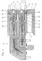
- the assembled coaxial connector partis shown, which here in one Receiving part 40 is attached. Furthermore, there is a complementary plug part 42 shown, which is inserted into the assembled coaxial connector part.
- the Complementary connector parthas pin-shaped contacts 44 which in the Internal contacts 18 of the coaxial connector part are inserted.
- lower external contact 16can be clearly seen, as this obliquely in the housing 10 and is received in the retaining ring 11: the distance between the left end face of the retaining ring 11 and the paragraph 23 is much smaller than on the lower side on the upper side, since the external contact 16 together with the insulator 20 and the inner contact 18 counterclockwise relative to the housing 10 is twisted.
- This pivoting movement of the contact unittakes place by one Pivotal point that is approximately at the center of the ball head 30 of the internal contact 18 coincides.
- the unitconsists of external contact 16
- Internal contact 18 and insulator 20to a complementary inserted obliquely Adapts plug part, only for a rotary movement between the spring clip 34 and the ball head 30.
- This rotary movementcan despite the frictional forces between the ball head 30 and the spring clip 34 due to the large Distance between the free front end of the contact units 12, 14 and Pivot point on the ball head 30 can be achieved with low forces, since the acting forces have a large lever arm.
- These required forcesare significantly less than the forces required for translational movement between ball head and spring clip would be necessary, as a translational Movement does not benefit from the long lever arm.
Landscapes
- Coupling Device And Connection With Printed Circuit (AREA)
Abstract
Translated fromGerman
Description
Translated fromGermanDie Erfindung betrifft ein Koaxial-Steckerteil mit einem Gehäuse, einemInnenkontakt, einem Außenkontakt und einem Isolator, der zwischen demInnenkontakt und dem Außenkontakt angeordnet ist.The invention relates to a coaxial connector part with a housing, aInternal contact, an external contact and an insulator, which is between theInternal contact and the external contact is arranged.
Wenn ein solches Steckerteil in ein komplementäres Steckerteil eingesteckt wird,um eine Steckverbindung zu erzielen, besteht die Gefahr, daß die beidenSteckerteile relativ zu einer zentrierten Anordnung, bei der die Mittelachsen derSteckkontakte zusammenfallen, verschoben oder verdreht sind. Bei einer solchenFehlausrichtung können auf die Steckkontakte unerwünscht hohe Belastungenausgeübt werden. Diese Belastungen werden von den Kontakten zum Teil überdas Gehäuse und zum Teil direkt auf das Bauteil übertragen, an dem dasSteckerteil angebracht ist. Wenn die Kontakte mit den Bauteilen verlötet sind,insbesondere in SMT-Technik, besteht die Gefahr, daß die auf die Lötstelleeinwirkenden Belastungen zu einer Beschädigung der Lötstellen führen.If such a plug part is inserted into a complementary plug part,to achieve a plug connection, there is a risk that the twoConnector parts relative to a centered arrangement in which the central axes of thePlug contacts collapse, shift or are twisted. With oneMisalignment can place undesirable high loads on the plug contactsbe exercised. These burdens are partly overcome by the contactsthe housing and partly directly to the component on which thePlug part is attached. If the contacts are soldered to the components,especially in SMT technology, there is a risk that the on the solder jointloads can damage the solder joints.
Aus der WO 00/52788 ist ein Adapter bekannt, der zur Verbindung von zweiLeiterplatten dient, insbesondere auf dem Gebiet der Hochfrequenztechnik. Aneiner der Leiterplatten ist ein Sockelteil angebracht, das mit einem Kugelkopf versehen ist. Auf dem Kugelkopf ist schwenkbar ein Isolator angebracht, der miteinem Innenleiter und einem Außenleiter versehen ist. Der Isolator kann in einkomplementäres Sockelteil eingesteckt werden, das an der anderen Leiterplatteangebracht ist. Aufgrund der schwenkbaren Anordnung des Isolators kann einseitlicher Versatz zwischen den beiden Leiterplatten kompensiert werden. Durchunterschiedlich tiefes Einstecken des Isolators in das komplementäre Sockelteilkönnen Abstandsabweichungen der beiden Leiterplatten voneinander kompensiertwerden. Bei dem bekannten Adapter handelt es sich jedoch nicht um einSteckerteil, sondern um eine Koaxialverbindung, die zur dauerhaften Verbindungzwischen zwei Leiterplatten in einem Leiterplatten-Stapel dient. Auch ist derBauaufwand vergleichsweise hoch, da die Kontaktierung des Innenleiters und desAußenleiters bei der gelenkigen Anbringung des Isolators sehr aufwendig ist.From WO 00/52788 an adapter is known which is used to connect twoPrinted circuit boards are used, particularly in the field of high-frequency technology. OnOne of the circuit boards is attached to a base part, which has a ball headis provided. On the ball head an isolator is pivotally attached, which withan inner conductor and an outer conductor is provided. The insulator can be in oneComplementary base part to be inserted on the other circuit boardis appropriate. Due to the pivotable arrangement of the insulator, alateral offset between the two circuit boards can be compensated. Byinserting the insulator into the complementary base part at different depthscan compensate for differences in distance between the two circuit boardsbecome. However, the known adapter is not aPlug part, but a coaxial connection, which is used for permanent connectionserves between two circuit boards in a circuit board stack. That too isConstruction costs comparatively high, since the contacting of the inner conductor and theOuter conductor in the articulated attachment of the insulator is very expensive.
Die Aufgabe der Erfindung besteht darin, ein Koaxial-Steckerteil der eingangsgenannten Art dahingehend weiterzubilden, daß die Kontakte bei geringemBauaufwand geringeren Belastungen ausgesetzt werden, falls das Steckerteil miteiner Fehlausrichtung in ein komplementäres Steckerteil eingesetzt wird.The object of the invention is to provide a coaxial connector partmentioned type to the extent that the contacts at lowConstruction work to be exposed to lower loads if the connector part withmisalignment is inserted into a complementary connector part.
Zu diesem Zweck ist erfindungsgemäß vorgesehen, daß der Außenkontakt amGehäuse schwenkbar angebracht ist, wodurch auch der im Außenkontaktaufgenommene Isolator und der im Isolator aufgenommene Innenkontakt alsEinheit schwenkbar sind. Auf diese Weise ergibt sich ein besonders einfacherAufbau, da lediglich ein einziges Bauteil schwenkbar am Gehäuse angebrachtwerden muß, nämlich der Außenkontakt. Dennoch kann sich die aus Innenkontakt,Außenkontakt und Isolator bestehenden Kontakteinheit beim Einstecken deskomplementären Steckverbinders automatisch entsprechend der Fehlausrichtungder beiden Steckerteile ausrichten, so daß die Mittelachsen der ineinanderzusteckendenKontakte wieder zusammenfallen. Die Kontakte der beidenSteckerteile können dann leicht ineinandergeschoben werden, ohne daßübermäßige Belastungen auftreten.For this purpose, the invention provides that the external contact onHousing is pivotally attached, which also means that in the external contactrecorded insulator and the internal contact recorded in the insulator asUnit are pivotable. This results in a particularly simple oneConstruction, since only a single component is pivotally attached to the housingmust be, namely the external contact. Nevertheless, the internal contact,External contact and isolator existing contact unit when inserting thecomplementary connector automatically according to the misalignmentalign the two connector parts so that the central axes of the nested onesContacts collapse again. The contacts of the twoPlug parts can then be easily pushed into one another withoutexcessive loads occur.
Gemäß der bevorzugten Ausführungsform ist vorgesehen, daß der Innenkontaktmit einem Kugelkopf versehen ist, auf den eine Federklammer aufgeschoben ist,die in SMT-Technik mit einer Leiterplatte verbunden werden kann. Die Verwendung eines Kugelkopfes ergibt eine kugelgelenkartige Verbindungzwischen dem Innenkontakt und der Federklammer, so daß sich dieKontakteinheit relativ zur Federklammer verstellen kann, ohne daß eineBewegung auf die Federklammer übertragen wird. Dies gewährleistet, daß dieSMT-Lötstelle, mittels der die Federklammer mit der Leiterplatte verbundenwerden kann, keinen Belastungen ausgesetzt wird. Der Beitrag derkugelgelenkartigen Verbindung zwischen dem Innenkontakt und derFederklammer zur schwenkbaren Anbringung der Kontakteinheit istvernachlässigbar.According to the preferred embodiment it is provided that the internal contactis provided with a ball head onto which a spring clip is slid,which can be connected to a printed circuit board using SMT technology. TheUsing a ball head results in a ball joint-like connectionbetween the internal contact and the spring clip, so that theContact unit can be adjusted relative to the spring clip without aMotion is transmitted to the spring clip. This ensures that theSMT solder joint, by means of which the spring clip is connected to the circuit boardcan be exposed to no stress. The contribution ofball joint-like connection between the internal contact and theSpring clip for pivoting attachment of the contact unit isnegligible.
Vorzugsweise ist vorgesehen, daß der Kugelkopf etwa mit dem Drehpunkt derKontakteinheit im Gehäuse zusammenfällt. Dies gewährleistet, daß es zu keinertranslatorischen Bewegung zwischen Federklammer und Innenkontakt kommt,wenn die Einheit aus Innenkontakt, Außenkontakt und Isolator relativ zumGehäuse verschwenkt wird, sondern es lediglich zu einer Verdrehung um wenigeWinkelgrade kommt.It is preferably provided that the ball head approximately with the pivot point of theContact unit in the housing coincides. This ensures that there is nonetranslational movement between spring clip and internal contact comes,if the unit of internal contact, external contact and insulator relative toHousing is pivoted, but it only rotates by a fewAngular degrees is coming.
Vorteilhafte Ausgestaltungen der Erfindung ergeben sich aus denUnteransprüchen.Advantageous embodiments of the invention result from theDependent claims.
Die Erfindung wird nachfolgend anhand einer bevorzugten Ausführungsformbeschrieben, die in den beigefügten Zeichnungen dargestellt ist. In diesen zeigen:
- Figur 1 in einer perspektivischen Ansicht ein erfindungsgemäßes Koaxial-Steckerteil;
- Figur 2 in einer perspektivischen Explosionsansicht das Koaxial-Steckerteil vonFigur 1; und
- Figur 3 in einer Schnittansicht das Koaxial-Steckerteil von Figur 1 zusammen miteinem komplementären Steckerteil.
- Figure 1 is a perspective view of a coaxial connector part according to the invention;
- Figure 2 is an exploded perspective view of the coaxial connector part of Figure 1; and
- Figure 3 is a sectional view of the coaxial connector part of Figure 1 together with a complementary connector part.
In den Figuren 1 und 2 ist ein Koaxial-Steckerteil gezeigt, das als wichtigsteBauteile ein Gehäuse 10 sowie zwei Kontakteinheiten 12, 14 enthält, die am Gehäuse 10 befestigt sind. Jede Kontakteinheit ist gebildet aus einemAußenkontakt 16, einem Innenkontakt 18 und einem Isolator 20.In Figures 1 and 2, a coaxial connector part is shown as the most importantComponents contain a
Das Gehäuse 10 besteht aus einem elektrisch isolierenden Material, beispielsweiseKunststoff, und weist zwei Öffnungen zur Aufnahme der Kontakteinheitenauf. Den Öffnungen ist jeweils ein Haltering 11 zugeordnet, dessen Funktionspäter erläutert wird.The
Der Außenkontakt 16 besteht aus einem elektrisch leitfähigen Material und weistan seinem dem Gehäuse 10 zugeordneten Ende eine hülsenförmige Schürze 22auf, die mit zwei Aussparungen 24 versehen ist. Das freie Ende der Schürze 22 istmit einem umlaufenden, von den beiden Aussparungen 24 unterbrochenenVorsprung versehen, so daß das freie Ende zwei Rasthaken 25 bildet. AmÜbergang der Schürze 22 in den Körper des Außenkontakts 16 ist ein Absatz 23vorgesehen. Am entgegengesetzten Ende ist der Außenkontakt mit mehrerenelastischen Zungen 26 versehen.The
Der Isolator 20 besteht aus einem elektrisch isolierenden Material und ist mit zweieinander gegenüberliegenden Nasen 28 versehen, deren Abmessungen soausgeführt sind, daß sie in die Aussparungen 24 des Außenkontakts 16eingeschoben werden können.The
Der Innenkontakt 18 besteht aus einem elektrisch leitenden Material und ist hierals Hülse ausgeführt, deren eines Ende geschlitzt und deren anderes Ende miteinem Kugelkopf 30 versehen ist. Der Innenkontakt 18 ist ferner mit einemRastbund 32 versehen.The
Dem Innenkontakt 18 ist eine Federklammer 34 zugeordnet, die eine U-förmigeGestalt hat. Die beiden einander gegenüberliegenden Schenkel der Federklammer34 sind dafür vorgesehen, am Kugelkopf 30 des Innenkontakts elastischanzugreifen. Der die beiden Schenkel miteinander verbindende Steg derFederklammer ist dafür vorgesehen, in SMT-Technik mit einer elektrisch leitendenFläche verbunden zu werden.The
Das Koaxial-Steckerteil wird in der folgenden Weise montiert: Zunächst wird derHaltering 11 im Gehäuse 10 befestigt. Die im Gehäuse liegende Stirnseite desHalterings 11 bildet dann einen Hinterschnitt, der bei einer einstückigenAusgestaltung des Gehäuses 10 nur sehr schwer herstellbar wäre. Anschließendwird der Isolator 20 so in den Außenkontakt 16 eingeschoben, daß die Nasen 28in die Aussparungen 24 eingreifen. Der Außenkontakt 16 zusammen mit demIsolator 20 wird dann in den Haltering 11 eingeschoben, wobei die Rasthaken 25hinter die Stirnseite des Halterings 11 schnappen. Der Abstand zwischen denRasthaken 25 und dem Absatz 23 des Außenkontaktes 16 ist größer als die Längedes Halterings 11, so daß in axialer Richtung ein gewisses Spiel vorliegt. Fernerist der Innendurchmesser des Halterings 11 größer als der Außendurchmesser derSchürze 22, so daß auch in radialer Richtung ein Spiel vorhanden ist.The coaxial connector part is assembled in the following way: First theRetaining
Der Innenkontakt 18 wird in den im Gehäuse 10 montierten Isolator 20 von deranderen Seite eingesetzt als der Isolator und der Außenkontakt 16, wie in Figur 2gezeigt ist. Dabei rastet der Rastbund 32 des Innenkontakts 18 im Inneren desIsolators 20 ein, so daß der Innenkontakt fest aufgenommen ist. Schließlich wirdauf den Kugelkopf 30 des Innenkontaktes 18 die Federklammer 34 aufgeschoben.Somit ist das Koaxial-Steckerteil fertig montiert. Das wichtige Merkmal bestehtdarin, daß im wesentlichen nur der Außenkontakt 16 für die schwenkbareAnbringung der Kontakteinheit am Gehäuse verantwortlich ist. Die Schwenkbarkeitergibt sich aufgrund des radialen und axialen Spiels zwischen dem Haltering 11und der Schürze 22 im Gehäuse.The
In Figur 3 ist das montierte Koaxial-Steckerteil gezeigt, das hier in einemAufnahmeteil 40 angebracht ist. Weiterhin ist ein komplementäres Steckerteil 42gezeigt, das in das montierte Koaxial-Steckerteil eingesteckt ist. Daskomplementäre Steckerteil weist stiftförmige Kontakte 44 auf, die in dieInnenkontakte 18 des Koaxial-Steckerteils eingeschoben sind. Am in Figur 3unteren Außenkontakt 16 ist deutlich zu sehen, wie dieser schräg im Gehäuse 10und im Haltering 11 aufgenommen ist: Der Abstand zwischen der linken Stirnseitedes Halterings 11 und dem Absatz 23 ist auf der unteren Seite sehr viel kleiner alsauf der oberen Seite, da der Außenkontakt 16 zusammen mit dem Isolator 20 unddem Innenkontakt 18 relativ zum Gehäuse 10 entgegen dem Uhrzeigersinn verdreht ist. Diese Schwenkbewegung der Kontakteinheit erfolgt um einenDrehpunkt, der etwa mit dem Mittelpunkt des Kugelkopfes 30 des Innenkontakts18 zusammenfällt. Somit kommt es, wenn sich die Einheit aus Außenkontakt 16,Innenkontakt 18 und Isolator 20 an ein schief eingestecktes komplementäresSteckerteil anpaßt, lediglich zu einer Drehbewegung zwischen der Federklammer34 und dem Kugelkopf 30. Diese Drehbewegung kann trotz der Reibungskräftezwischen dem Kugelkopf 30 und der Federklammer 34 aufgrund des großenAbstandes zwischen dem freien Vorderende der Kontakteinheiten 12, 14 und demDrehpunkt auf dem Kugelkopf 30 mit geringen Kräften erzielt werden, da dieeinwirkenden Kräfte einen großen Hebelarm haben. Diese erforderlichen Kräftesind erheblich geringer als die Kräfte, die für eine translatorische Bewegungzwischen Kugelkopf und Federklammer notwendig wären, da eine translatorischeBewegung nicht vom langen Hebelarm profitiert.In Figure 3, the assembled coaxial connector part is shown, which here in one
- 10:10:
- Gehäusecasing
- 11:11:
- Halteringretaining ring
- 12:12:
- KontakteinheitContact unit
- 14:14:
- KontakteinheitContact unit
- 16:16:
- Außenkontaktoutside Contact
- 18:18:
- Innenkontaktinternal contact
- 20:20:
- Isolatorinsulator
- 22:22:
- Schürzeapron
- 23:23:
- Absatzparagraph
- 24:24:
- Aussparungrecess
- 25:25:
- Rasthakenlatch hook
- 26:26:
- Zungetongue
- 28:28:
- Nasenose
- 30:30:
- Kugelkopfball head
- 32:32:
- Rastbundlocking collar
- 34:34:
- Federklammerspring clip
- 40:40:
- Aufnahmeteilreceiving part
- 42:42:
- Komplementäres SteckerteilComplementary connector part
- 44:44:
- Stiftkontaktpin contact
Claims (8)
Translated fromGermanApplications Claiming Priority (2)
| Application Number | Priority Date | Filing Date | Title |
|---|---|---|---|
| DE10115479ADE10115479A1 (en) | 2001-03-29 | 2001-03-29 | Coaxial plug member |
| DE10115479 | 2001-03-29 |
Publications (3)
| Publication Number | Publication Date |
|---|---|
| EP1246304A2true EP1246304A2 (en) | 2002-10-02 |
| EP1246304A3 EP1246304A3 (en) | 2003-06-25 |
| EP1246304B1 EP1246304B1 (en) | 2005-09-07 |
Family
ID=7679503
Family Applications (1)
| Application Number | Title | Priority Date | Filing Date |
|---|---|---|---|
| EP02005377AExpired - LifetimeEP1246304B1 (en) | 2001-03-29 | 2002-03-15 | Coaxial connector |
Country Status (7)
| Country | Link |
|---|---|
| US (1) | US6705875B2 (en) |
| EP (1) | EP1246304B1 (en) |
| JP (1) | JP3683541B2 (en) |
| KR (1) | KR100480215B1 (en) |
| CN (1) | CN1170344C (en) |
| CA (1) | CA2377275C (en) |
| DE (2) | DE10115479A1 (en) |
Cited By (2)
| Publication number | Priority date | Publication date | Assignee | Title |
|---|---|---|---|---|
| FR2938382A1 (en)* | 2008-11-08 | 2010-05-14 | Nicomatic Sa | ELECTRICAL CONNECTION ELEMENT AND ELECTRICAL CONNECTOR THEREFOR |
| US7717716B2 (en) | 2007-12-08 | 2010-05-18 | Harting Electronics Gmbh & Co. Kg | Pivoting printed board connector |
Families Citing this family (52)
| Publication number | Priority date | Publication date | Assignee | Title |
|---|---|---|---|---|
| US6935866B2 (en)* | 2002-04-02 | 2005-08-30 | Adc Telecommunications, Inc. | Card edge coaxial connector |
| US7077697B2 (en)* | 2004-09-09 | 2006-07-18 | Corning Gilbert Inc. | Snap-in float-mount electrical connector |
| US7086897B2 (en) | 2004-11-18 | 2006-08-08 | John Mezzalingua Associates, Inc. | Compression connector and method of use |
| US7114990B2 (en) | 2005-01-25 | 2006-10-03 | Corning Gilbert Incorporated | Coaxial cable connector with grounding member |
| US7018216B1 (en)* | 2005-06-06 | 2006-03-28 | Harris Corporation | Coaxial connector for circuit boards |
| DE202005020107U1 (en) | 2005-12-23 | 2007-02-15 | Kathrein-Werke Kg | On a printed circuit board electrically connected coaxial H-connector device and associated connector unit |
| WO2007107883A2 (en) | 2006-03-23 | 2007-09-27 | Walker Digital, Llc | Content determinative game systems and methods for keno and lottery games |
| US7374455B2 (en)* | 2006-10-19 | 2008-05-20 | John Mezzalingua Associates, Inc. | Connector assembly for a cable having a radially facing conductive surface and method of operatively assembling the connector assembly |
| US7500873B1 (en)* | 2008-05-16 | 2009-03-10 | Corning Gilbert Inc. | Snap-on coaxial cable connector |
| US20100015850A1 (en)* | 2008-07-15 | 2010-01-21 | Casey Roy Stein | Low-profile mounted push-on connector |
| GB2469023B (en)* | 2009-03-30 | 2013-01-02 | Tyco Electronics Ltd Uk | Coaxial connector and method of assembling one |
| JP5286190B2 (en)* | 2009-08-03 | 2013-09-11 | 富士通コンポーネント株式会社 | Coaxial connector and connector device |
| TWI549386B (en) | 2010-04-13 | 2016-09-11 | 康寧吉伯特公司 | Coaxial connector with inhibited ingress and improved grounding |
| US8888526B2 (en) | 2010-08-10 | 2014-11-18 | Corning Gilbert, Inc. | Coaxial cable connector with radio frequency interference and grounding shield |
| TWI558022B (en) | 2010-10-27 | 2016-11-11 | 康寧吉伯特公司 | Push-on cable connector with a coupler and retention and release mechanism |
| US9190744B2 (en) | 2011-09-14 | 2015-11-17 | Corning Optical Communications Rf Llc | Coaxial cable connector with radio frequency interference and grounding shield |
| US20130072057A1 (en) | 2011-09-15 | 2013-03-21 | Donald Andrew Burris | Coaxial cable connector with integral radio frequency interference and grounding shield |
| CN103187646B (en)* | 2011-12-28 | 2015-05-27 | 富泰华工业(深圳)有限公司 | Power supply bolt structure |
| US9136654B2 (en) | 2012-01-05 | 2015-09-15 | Corning Gilbert, Inc. | Quick mount connector for a coaxial cable |
| US9407016B2 (en) | 2012-02-22 | 2016-08-02 | Corning Optical Communications Rf Llc | Coaxial cable connector with integral continuity contacting portion |
| US8888519B2 (en)* | 2012-05-31 | 2014-11-18 | Cinch Connectivity Solutions, Inc. | Modular RF connector system |
| US9246244B2 (en)* | 2012-06-25 | 2016-01-26 | Dish Network L.L.C. | RF connector with push-on connection |
| US9106035B2 (en) | 2012-06-25 | 2015-08-11 | Dish Network L.L.C. | RF connector with push-on connection |
| US9287659B2 (en) | 2012-10-16 | 2016-03-15 | Corning Optical Communications Rf Llc | Coaxial cable connector with integral RFI protection |
| US9147963B2 (en) | 2012-11-29 | 2015-09-29 | Corning Gilbert Inc. | Hardline coaxial connector with a locking ferrule |
| US9735521B2 (en) | 2013-01-09 | 2017-08-15 | Amphenol Corporation | Float adapter for electrical connector |
| US9039433B2 (en)* | 2013-01-09 | 2015-05-26 | Amphenol Corporation | Electrical connector assembly with high float bullet adapter |
| US9356374B2 (en) | 2013-01-09 | 2016-05-31 | Amphenol Corporation | Float adapter for electrical connector |
| US9153911B2 (en) | 2013-02-19 | 2015-10-06 | Corning Gilbert Inc. | Coaxial cable continuity connector |
| US8882539B2 (en) | 2013-03-14 | 2014-11-11 | Amphenol Corporation | Shunt for electrical connector |
| US9172154B2 (en) | 2013-03-15 | 2015-10-27 | Corning Gilbert Inc. | Coaxial cable connector with integral RFI protection |
| CN105247738A (en)* | 2013-04-18 | 2016-01-13 | 富加宜(亚洲)私人有限公司 | Electrical connector system |
| US10290958B2 (en) | 2013-04-29 | 2019-05-14 | Corning Optical Communications Rf Llc | Coaxial cable connector with integral RFI protection and biasing ring |
| CN105284015B (en) | 2013-05-20 | 2019-03-08 | 康宁光电通信Rf有限责任公司 | Coaxial cable connector with whole RFI protection |
| US9548557B2 (en) | 2013-06-26 | 2017-01-17 | Corning Optical Communications LLC | Connector assemblies and methods of manufacture |
| US9048599B2 (en) | 2013-10-28 | 2015-06-02 | Corning Gilbert Inc. | Coaxial cable connector having a gripping member with a notch and disposed inside a shell |
| WO2016073309A1 (en) | 2014-11-03 | 2016-05-12 | Corning Optical Communications Rf Llc | Coaxial cable connector with integral rfi protection |
| US9595795B2 (en)* | 2014-12-09 | 2017-03-14 | Te Connectivity Corporation | Header assembly |
| US9590287B2 (en) | 2015-02-20 | 2017-03-07 | Corning Optical Communications Rf Llc | Surge protected coaxial termination |
| US10033122B2 (en) | 2015-02-20 | 2018-07-24 | Corning Optical Communications Rf Llc | Cable or conduit connector with jacket retention feature |
| US10211547B2 (en) | 2015-09-03 | 2019-02-19 | Corning Optical Communications Rf Llc | Coaxial cable connector |
| US9525220B1 (en) | 2015-11-25 | 2016-12-20 | Corning Optical Communications LLC | Coaxial cable connector |
| US9762007B2 (en) | 2016-02-10 | 2017-09-12 | Dish Network L.L.C. | Push on connector |
| US11527846B2 (en) | 2016-02-12 | 2022-12-13 | Commscope Technologies Llc | Ganged coaxial connector assembly |
| US10950970B2 (en) | 2018-04-04 | 2021-03-16 | Commscope Technologies Llc | Ganged coaxial connector assembly |
| US9837777B1 (en)* | 2016-08-30 | 2017-12-05 | Steren Electronics International, Llc | Expandable cable connector torque adapter |
| AU2019247776B2 (en)* | 2018-04-04 | 2023-07-20 | Outdoor Wireless Networks LLC | Ganged coaxial connector assembly |
| CN108324090A (en)* | 2018-04-16 | 2018-07-27 | 广东天际电器股份有限公司 | A kind of same shaft multifunctional detection stews device |
| CN208835397U (en)* | 2018-10-12 | 2019-05-07 | 上海莫仕连接器有限公司 | Coaxial connector |
| KR102025046B1 (en) | 2019-05-22 | 2019-09-25 | 윤형석 | Block toys |
| TWM618327U (en)* | 2020-12-15 | 2021-10-11 | 大陸商東莞立德精密工業有限公司 | Charging adapter |
| US12034264B2 (en) | 2021-03-31 | 2024-07-09 | Corning Optical Communications Rf Llc | Coaxial cable connector assemblies with outer conductor engagement features and methods for using the same |
Family Cites Families (18)
| Publication number | Priority date | Publication date | Assignee | Title |
|---|---|---|---|---|
| US2999998A (en)* | 1958-09-22 | 1961-09-12 | Fred H Cole | Self-aligning electrical connector assembly |
| US4580862A (en)* | 1984-03-26 | 1986-04-08 | Amp Incorporated | Floating coaxial connector |
| US4865558A (en)* | 1988-11-23 | 1989-09-12 | Amp Incorporated | Stabilizing bushing for electrical connector |
| JPH0277884U (en)* | 1988-12-01 | 1990-06-14 | ||
| US5217391A (en)* | 1992-06-29 | 1993-06-08 | Amp Incorporated | Matable coaxial connector assembly having impedance compensation |
| JP3093081B2 (en)* | 1993-06-25 | 2000-10-03 | 富士通株式会社 | Coaxial connector |
| JP2590727B2 (en)* | 1994-04-19 | 1997-03-12 | 日本電気株式会社 | Coaxial connector |
| US5516303A (en)* | 1995-01-11 | 1996-05-14 | The Whitaker Corporation | Floating panel-mounted coaxial connector for use with stripline circuit boards |
| JP3114789B2 (en)* | 1995-07-21 | 2000-12-04 | 兼藤産業株式会社 | Coaxial cable connector |
| DE29517358U1 (en)* | 1995-11-02 | 1996-01-11 | Harting Elektronik Gmbh, 32339 Espelkamp | Coaxial connector |
| US5769652A (en)* | 1996-12-31 | 1998-06-23 | Applied Engineering Products, Inc. | Float mount coaxial connector |
| JP3302932B2 (en)* | 1998-09-07 | 2002-07-15 | 小峰無線電機株式会社 | SMA connector |
| JP3358999B2 (en)* | 1999-02-09 | 2002-12-24 | ヒロセ電機株式会社 | Coaxial connector |
| ATE244943T1 (en)* | 1999-03-02 | 2003-07-15 | Huber+Suhner Ag | PCB COAXIAL CONNECTION |
| DE19927713C1 (en)* | 1999-06-17 | 2001-01-18 | Kathrein Werke Kg | Multi-purpose coupler for single-pole or multi-pole screened HF socket plug uses axially displaced clamp rail for providing contact clamp force between plug pin and corresponding socket |
| DE19942579A1 (en)* | 1999-09-07 | 2001-03-08 | Harting Kgaa | Coaxial connector |
| DE19960856A1 (en)* | 1999-12-16 | 2001-06-28 | Harting Kgaa | Connectors |
| US6558177B2 (en)* | 2000-11-22 | 2003-05-06 | Tyco Electronics Corporation | Floating coaxial connector |
- 2001
- 2001-03-29DEDE10115479Apatent/DE10115479A1/ennot_activeWithdrawn
- 2002
- 2002-03-15DEDE50204142Tpatent/DE50204142D1/ennot_activeExpired - Lifetime
- 2002-03-15EPEP02005377Apatent/EP1246304B1/ennot_activeExpired - Lifetime
- 2002-03-18CACA002377275Apatent/CA2377275C/ennot_activeExpired - Fee Related
- 2002-03-25USUS10/107,101patent/US6705875B2/ennot_activeExpired - Lifetime
- 2002-03-26KRKR10-2002-0016322Apatent/KR100480215B1/ennot_activeExpired - Fee Related
- 2002-03-28CNCNB021083215Apatent/CN1170344C/ennot_activeExpired - Fee Related
- 2002-03-28JPJP2002090849Apatent/JP3683541B2/ennot_activeExpired - Fee Related
Cited By (4)
| Publication number | Priority date | Publication date | Assignee | Title |
|---|---|---|---|---|
| US7717716B2 (en) | 2007-12-08 | 2010-05-18 | Harting Electronics Gmbh & Co. Kg | Pivoting printed board connector |
| FR2938382A1 (en)* | 2008-11-08 | 2010-05-14 | Nicomatic Sa | ELECTRICAL CONNECTION ELEMENT AND ELECTRICAL CONNECTOR THEREFOR |
| WO2010052320A1 (en)* | 2008-11-08 | 2010-05-14 | Nicomatic Sa | Electric connector, and corresponding electric connection element, electric linking member, and assembling method |
| US8573983B2 (en) | 2008-11-08 | 2013-11-05 | Nicomatic Sa | Electronic connector, and corresponding electric connection element, electric linking member, and assembling method |
Also Published As
| Publication number | Publication date |
|---|---|
| EP1246304B1 (en) | 2005-09-07 |
| CN1379512A (en) | 2002-11-13 |
| DE50204142D1 (en) | 2005-10-13 |
| DE10115479A1 (en) | 2002-10-10 |
| US6705875B2 (en) | 2004-03-16 |
| JP3683541B2 (en) | 2005-08-17 |
| CN1170344C (en) | 2004-10-06 |
| EP1246304A3 (en) | 2003-06-25 |
| CA2377275A1 (en) | 2002-09-29 |
| KR100480215B1 (en) | 2005-04-06 |
| US20020142625A1 (en) | 2002-10-03 |
| CA2377275C (en) | 2006-10-10 |
| KR20020077100A (en) | 2002-10-11 |
| JP2002298996A (en) | 2002-10-11 |
Similar Documents
| Publication | Publication Date | Title |
|---|---|---|
| EP1246304B1 (en) | Coaxial connector | |
| EP1157448B1 (en) | Coaxial connection for a printed circuit board | |
| DE60000187T2 (en) | Coaxial connector for connecting two circuit boards | |
| DE69700120T2 (en) | Spring contact element | |
| EP2529451B1 (en) | Circuit board coaxial connector | |
| EP1275173B1 (en) | Plug-in connector with a bushing | |
| EP2068403B1 (en) | Swivelling circuit board plug-in connector | |
| DE69931103T2 (en) | female contact | |
| DE60113948T2 (en) | Floating coaxial connector | |
| EP2187480B1 (en) | Socket for printed circuit boards | |
| EP0772261A2 (en) | Coaxial connector | |
| EP1231679A1 (en) | Connector composed of a male and female part | |
| DE69221428T2 (en) | Electrical contact socket | |
| DE69612352T2 (en) | Holding and contact element in one connector | |
| EP3605746B1 (en) | Plug connector and connection with such a connector | |
| DE1953301B2 (en) | CONNECTOR | |
| EP3782235A1 (en) | Direct plug connector | |
| DE102005026030A1 (en) | Improved coaxial connector | |
| DE102004042671B4 (en) | Electrical jack and electrical plug connection | |
| DE2026386A1 (en) | Plug coupling and plug for electrical line connections | |
| DE69710233T2 (en) | Connector for a coaxial cable and method for mounting the connector on the end of a coaxial cable. | |
| DE102005016265B4 (en) | Locking a locking element with Radsok socket | |
| DE102016110946B4 (en) | adapter plug | |
| EP4070413B1 (en) | Plug connection for transmitting electrical energy | |
| DE102008004162A1 (en) | Terminal contact, IC test socket and procedure |
Legal Events
| Date | Code | Title | Description |
|---|---|---|---|
| PUAI | Public reference made under article 153(3) epc to a published international application that has entered the european phase | Free format text:ORIGINAL CODE: 0009012 | |
| AK | Designated contracting states | Kind code of ref document:A2 Designated state(s):AT BE CH CY DE DK ES FI FR GB GR IE IT LI LU MC NL PT SE TR | |
| AX | Request for extension of the european patent | Free format text:AL;LT;LV;MK;RO;SI | |
| PUAL | Search report despatched | Free format text:ORIGINAL CODE: 0009013 | |
| AK | Designated contracting states | Designated state(s):AT BE CH CY DE DK ES FI FR GB GR IE IT LI LU MC NL PT SE TR | |
| AX | Request for extension of the european patent | Extension state:AL LT LV MK RO SI | |
| RIC1 | Information provided on ipc code assigned before grant | Ipc:7H 01R 9/05 A Ipc:7H 01R 13/646 B Ipc:7H 01R 13/631 B | |
| 17P | Request for examination filed | Effective date:20030909 | |
| AKX | Designation fees paid | Designated state(s):DE FI FR GB SE | |
| 17Q | First examination report despatched | Effective date:20040213 | |
| RAP1 | Party data changed (applicant data changed or rights of an application transferred) | Owner name:HARTING ELECTRONICS GMBH & CO. KG | |
| GRAP | Despatch of communication of intention to grant a patent | Free format text:ORIGINAL CODE: EPIDOSNIGR1 | |
| GRAS | Grant fee paid | Free format text:ORIGINAL CODE: EPIDOSNIGR3 | |
| GRAA | (expected) grant | Free format text:ORIGINAL CODE: 0009210 | |
| AK | Designated contracting states | Kind code of ref document:B1 Designated state(s):DE FI FR GB SE | |
| PG25 | Lapsed in a contracting state [announced via postgrant information from national office to epo] | Ref country code:FI Free format text:LAPSE BECAUSE OF FAILURE TO SUBMIT A TRANSLATION OF THE DESCRIPTION OR TO PAY THE FEE WITHIN THE PRESCRIBED TIME-LIMIT Effective date:20050907 | |
| REG | Reference to a national code | Ref country code:GB Ref legal event code:FG4D Free format text:NOT ENGLISH | |
| REF | Corresponds to: | Ref document number:50204142 Country of ref document:DE Date of ref document:20051013 Kind code of ref document:P | |
| GBT | Gb: translation of ep patent filed (gb section 77(6)(a)/1977) | Effective date:20051101 | |
| PG25 | Lapsed in a contracting state [announced via postgrant information from national office to epo] | Ref country code:SE Free format text:LAPSE BECAUSE OF FAILURE TO SUBMIT A TRANSLATION OF THE DESCRIPTION OR TO PAY THE FEE WITHIN THE PRESCRIBED TIME-LIMIT Effective date:20051207 | |
| PLBE | No opposition filed within time limit | Free format text:ORIGINAL CODE: 0009261 | |
| STAA | Information on the status of an ep patent application or granted ep patent | Free format text:STATUS: NO OPPOSITION FILED WITHIN TIME LIMIT | |
| 26N | No opposition filed | Effective date:20060608 | |
| REG | Reference to a national code | Ref country code:FR Ref legal event code:RN | |
| PG25 | Lapsed in a contracting state [announced via postgrant information from national office to epo] | Ref country code:FR Free format text:LAPSE BECAUSE OF FAILURE TO SUBMIT A TRANSLATION OF THE DESCRIPTION OR TO PAY THE FEE WITHIN THE PRESCRIBED TIME-LIMIT Effective date:20061020 | |
| EN | Fr: translation not filed | ||
| REG | Reference to a national code | Ref country code:FR Ref legal event code:FC | |
| ET | Fr: translation filed | ||
| PGFP | Annual fee paid to national office [announced via postgrant information from national office to epo] | Ref country code:GB Payment date:20120327 Year of fee payment:11 | |
| GBPC | Gb: european patent ceased through non-payment of renewal fee | Effective date:20130315 | |
| PG25 | Lapsed in a contracting state [announced via postgrant information from national office to epo] | Ref country code:GB Free format text:LAPSE BECAUSE OF NON-PAYMENT OF DUE FEES Effective date:20130315 | |
| REG | Reference to a national code | Ref country code:FR Ref legal event code:PLFP Year of fee payment:15 | |
| REG | Reference to a national code | Ref country code:DE Ref legal event code:R082 Ref document number:50204142 Country of ref document:DE Ref country code:DE Ref legal event code:R081 Ref document number:50204142 Country of ref document:DE Owner name:HARTING ELECTRONICS GMBH, DE Free format text:FORMER OWNER: HARTING ELECTRONICS GMBH & CO. KG, 32339 ESPELKAMP, DE | |
| REG | Reference to a national code | Ref country code:FR Ref legal event code:PLFP Year of fee payment:16 | |
| PGFP | Annual fee paid to national office [announced via postgrant information from national office to epo] | Ref country code:FR Payment date:20170213 Year of fee payment:16 Ref country code:DE Payment date:20170307 Year of fee payment:16 | |
| REG | Reference to a national code | Ref country code:DE Ref legal event code:R119 Ref document number:50204142 Country of ref document:DE | |
| PG25 | Lapsed in a contracting state [announced via postgrant information from national office to epo] | Ref country code:DE Free format text:LAPSE BECAUSE OF NON-PAYMENT OF DUE FEES Effective date:20181002 | |
| PG25 | Lapsed in a contracting state [announced via postgrant information from national office to epo] | Ref country code:FR Free format text:LAPSE BECAUSE OF FAILURE TO SUBMIT A TRANSLATION OF THE DESCRIPTION OR TO PAY THE FEE WITHIN THE PRESCRIBED TIME-LIMIT Effective date:20180331 |