EP1244387B1 - Pedicle screws with inclined channels to hold support rods - Google Patents
Pedicle screws with inclined channels to hold support rodsDownload PDFInfo
- Publication number
- EP1244387B1 EP1244387B1EP00981564AEP00981564AEP1244387B1EP 1244387 B1EP1244387 B1EP 1244387B1EP 00981564 AEP00981564 AEP 00981564AEP 00981564 AEP00981564 AEP 00981564AEP 1244387 B1EP1244387 B1EP 1244387B1
- Authority
- EP
- European Patent Office
- Prior art keywords
- channel
- screw
- plug
- longitudinal
- rod
- Prior art date
- Legal status (The legal status is an assumption and is not a legal conclusion. Google has not performed a legal analysis and makes no representation as to the accuracy of the status listed.)
- Expired - Lifetime
Links
- 230000000903blocking effectEffects0.000description16
- 210000000988bone and boneAnatomy0.000description11
- 238000004873anchoringMethods0.000description8
- 238000000034methodMethods0.000description2
- 210000003205muscleAnatomy0.000description2
- 210000001519tissueAnatomy0.000description2
- 238000003780insertionMethods0.000description1
- 230000037431insertionEffects0.000description1
- 230000007170pathologyEffects0.000description1
Images


Classifications
- A—HUMAN NECESSITIES
- A61—MEDICAL OR VETERINARY SCIENCE; HYGIENE
- A61B—DIAGNOSIS; SURGERY; IDENTIFICATION
- A61B17/00—Surgical instruments, devices or methods
- A61B17/56—Surgical instruments or methods for treatment of bones or joints; Devices specially adapted therefor
- A61B17/58—Surgical instruments or methods for treatment of bones or joints; Devices specially adapted therefor for osteosynthesis, e.g. bone plates, screws or setting implements
- A61B17/68—Internal fixation devices, including fasteners and spinal fixators, even if a part thereof projects from the skin
- A61B17/70—Spinal positioners or stabilisers, e.g. stabilisers comprising fluid filler in an implant
- A61B17/7001—Screws or hooks combined with longitudinal elements which do not contact vertebrae
- A61B17/7032—Screws or hooks with U-shaped head or back through which longitudinal rods pass
- A61B17/7034—Screws or hooks with U-shaped head or back through which longitudinal rods pass characterised by a lateral opening
- A—HUMAN NECESSITIES
- A61—MEDICAL OR VETERINARY SCIENCE; HYGIENE
- A61B—DIAGNOSIS; SURGERY; IDENTIFICATION
- A61B17/00—Surgical instruments, devices or methods
- A61B17/56—Surgical instruments or methods for treatment of bones or joints; Devices specially adapted therefor
- A61B17/58—Surgical instruments or methods for treatment of bones or joints; Devices specially adapted therefor for osteosynthesis, e.g. bone plates, screws or setting implements
- A61B17/68—Internal fixation devices, including fasteners and spinal fixators, even if a part thereof projects from the skin
- A61B17/70—Spinal positioners or stabilisers, e.g. stabilisers comprising fluid filler in an implant
- A61B17/7001—Screws or hooks combined with longitudinal elements which do not contact vertebrae
- A61B17/7002—Longitudinal elements, e.g. rods
- A61B17/701—Longitudinal elements with a non-circular, e.g. rectangular, cross-section
- A—HUMAN NECESSITIES
- A61—MEDICAL OR VETERINARY SCIENCE; HYGIENE
- A61B—DIAGNOSIS; SURGERY; IDENTIFICATION
- A61B17/00—Surgical instruments, devices or methods
- A61B17/56—Surgical instruments or methods for treatment of bones or joints; Devices specially adapted therefor
- A61B17/58—Surgical instruments or methods for treatment of bones or joints; Devices specially adapted therefor for osteosynthesis, e.g. bone plates, screws or setting implements
- A61B17/68—Internal fixation devices, including fasteners and spinal fixators, even if a part thereof projects from the skin
- A61B17/84—Fasteners therefor or fasteners being internal fixation devices
- A61B17/86—Pins or screws or threaded wires; nuts therefor
- A61B17/8625—Shanks, i.e. parts contacting bone tissue
Definitions
- the present inventionrelates to bone screws with a thread adapted to be screwed into a bone, and a fixing means located the other end that is designed for attaching a spinal rod to the screw.
- the present inventionprovides a bolt for connecting a vertebra to a longitudinal member, comprising:
- the channelmay be formed such that its longitudinal axial plane is inclined relative to the longitudinal axis of the bone-anchoring member.
- the pedicle screw 1 represented in Figures 1 to 3is intended to form part of instrumentation for supporting the spine.
- This instrumentationhas at least one support rod dimensioned to extend along at least two vertebrae and at least two pedicle screws for bone anchoring, such as pedicle screw 1.
- Screw 1has a threaded rod 2 provided with a bone thread 3 and a longitudinal axis X-X, and a head 4 in which there is a channel 5 having a U-shaped cross section and a longitudinal axial plane P.
- the channel 5, delimited by two flanks 6, 7 of the head 4is adapted to receive a generally cylindrical support rod and for this purpose preferably has a bottom 8 of circular cross section.
- This rodcan be smooth or have a roughened surface or it can be the type of rod 36 which will be described below.
- the U-shaped channel 5is formed such that its longitudinal axial plane P is inclined by an angle A different from zero degrees relative to the longitudinal axis X-X of threaded rod 2.
- the rectilinear walls 9, which delimit either side of threaded parts 10 and channel 5 with its circular bottom 8,have an inclination A relative to the axis X-X.
- This inclination Acan have a value preferentially up to about 65 degrees (cf. Fig. 19-20) in either direction.
- the flanks 6 and 7 delimiting the U-shaped channel 5may have different respective widths 11, 12 in a direction perpendicular to the longitudinal axial plane P.
- a threaded hole 11is formed in the flank 7 whose width 12 is the greater. This hole 11 is intended to receive a threaded member such as a screw 12 ( Figure 7) for fixing a piece to the screw 1, for example an instrument 13 ( Figures 6 - 7).
- Instrument 13has a general tubular shape with an angled lower end 14 in which there is an orifice 15 for introducing the screw 12 into the threaded hole 11. Also arranged in the instrument 13 is an axial bore 16 which is open to each end of instrument 13, the angled end 14 being adapted to be applied on the end faces of the branches 6, 7 while the screw 12 can be screwed into the hole 11, in such a way that the bore 16 is coaxial with the threaded parts 10 ( Figure 3).
- the geometry of the head 4 of the screw 1thus makes it possible to position the instrument 13 in such a way that a tool can be introduced axially into the bore 16, precisely and with ease into the axis of the channel 5, in order to easily carry out the screwing therein of a threaded plug for blocking the support rod passing through the channel 5.
- FIG. 4shows a screw 1 screwed into a pedicle of a vertebra V and also a screw 17, according to the prior art, screwed into the other pedicle of the same vertebra.
- the screw 17according to the prior art includes a head 18 which is integral with a threaded rod 19 and has a U-shaped channel 21 whose axial plane contains the longitudinal axis of the rod 19.
- the flanks 22 delimiting the channel 21are thus similar in their dimensions and are symmetrical in relation to this axial plane and to the axis of the rod 19.
- the screwing tool 23can be introduced into the channel 5 without coming into contact with the tissues M.
- Figure 5illustrates the use of a transverse connection device 24 by virtue of the design of the wider flank 7 of the screw 1.
- the end face of this wide flank 7is made up of a first plane part 25, situated in the plane of the plane face 26 forming the end of the flank 6, and of a second plane part 27 forming an obtuse angle with the plane part 25 ( Figure 1).
- the transverse connection device 24is made up of a plate 28 whose ends bear on the plane part 27 of two screws 1, and of two members 29 for blocking the plate 28 on the screws 1.
- Each member 29includes a threaded rod (not visible in Figure 5) passing through a corresponding orifice of the plate 28 and being screwed into the associated threaded hole 11.
- FIG 8shows two pedicle screws 31 and 32 for anchoring instrumentation for supporting the spine into bone.
- Each screwcomprises a core 33 of diameter d, equipped with a respective thread 34 and 35, each also having an external diameter d1, d2, and a head (not shown).
- the diameter d of the core 33is identical for both the screws 31, 32, while the external diameter of their respective threads 34, 35 increases from d1 to d2, for example from 5.5 to 7.5 mm.
- each screw such as 31, 32comprises a cylindrical core 33 whose diameter is constant for all the screws, while the external diameters d1, d2 of their respective threads 34, 35 increase from one screw to the other, between defined limits.
- These screwscan be of the conventional type, such as the screw 17 shown in Figure 4, or can be according to the invention, such as the screw 1.
- the identically rigid screws 31, 32 of this setdo not have too great a diameter in relation to that of the support rods with which they may be associated.
- the diameter of the core 33is of course chosen so that all the screws used in the spinal instrumentation in question have a sufficient mechanical strength, while the height of their thread varies from one screw to the other. In other words, the diameter of the core 33 of the screw remains identical from one screw to the other, irrespective of the external diameter of its thread.
- Figures 9 to 11illustrate another example in which a pedicle screw 1 is associated with a support rod 36 on which at least one longitudinal flat 37 is formed over at least part of the length of the rod 36, the remaining part 38 of which is cylindrical.
- two longitudinal flats 37are arranged on the rod 36 and positioned diametrically opposite each other over part of the length of the rod.
- these flats 37are identical, that is to say they are symmetrical with respect to the longitudinal axis Y-Y of the rod 37. For this reason, the latter has, in the longitudinal axial plane P of the channel 5 of the head 4, a different flexural strength depending on its orientation in this channel 5.
- the flat or flats 37can extend either perpendicular to the said axial longitudinal plane P of the channel 5 ( Figure 10) or parallel to it ( Figure 11). Between the flats 37, the rod 36 has two diametrically opposite parts 39 with contours of circular cross section.
- the rounded bottom 8 of the channel 5has a radius of curvature substantially equal to the radius of curvature of the circular parts 39. For this reason, when the rod 36 is positioned in such a way that its flats 37 are parallel to the axial plane P ( Figure 11), one of the circular contours 39 will bear on the circular bottom 8 by fitting it.
- the means for blocking the rod 36 in the channel 5, formed for example by a threaded plug 40,has a bearing face which comes into contact with the rod 36.
- the flat or flatsmake it possible to adapt the "stiffness" of the assembly to the pathology of the patient, by varying the orientation of the rod 37 ( Figures 10 and 11).
- the flats 37can be separated by a distance of 3 mm.
- the flanks 6, 7 of the screw 1can have equal widths.
- the function of the threaded hole 11can be provided by a threaded extension in the same location or by a geometry on the sides such as holes 60 or grooves 107 ( Figures 19 and 22), making it possible to grip the screw via an instrument.
- Figure 12illustrates instrumentation used in conjunction with prior art screws 52, including two cylindrical vertebral rods 50 extending along a segment of the spine comprising four vertebrae 51. These rods are also equipped with pedicle screws 1, which are equipped with threaded plugs 53 for blocking the rods 50, and also, at the ends of the said rods, with bone-anchoring hooks 52 also provided with threaded plugs 53.
- the pairs of screws 1are connected by transverse connection devices 24.
- cylindrical rods 50can be replaced by rods 36 with flats 37, and the plugs 53 can be replaced by plugs 40 or 41.
- Figures 13 to 15illustrate a first embodiment of a screw according to the present invention.
- the screw 61includes a head 62 consisting of two flanks 63, 64 of unequal width and delimiting between them a channel 65 of U-shaped profile. Formed on one side of the body 62 there is also a hole 66 for gripping the screw via an instrument (not shown).
- the means for blocking the support rod 50is a threaded plug 67 provided with a collar 68 which radially delimits two threaded parts 41 and 69.
- a threaded hole 71is formed which has an interruption 72 on its part contiguous with the channel 65, so as to communicate laterally with the latter.
- the collar 68has an asymmetrical profile formed by a flank 68a, inclined in such a way as to be able to bear on the rod 50 at the end of screwing of the plug 67, and a second flank 68b extending radially, almost perpendicular to the longitudinal axis or me plug 67.
- the head of the screw 75consists of a short and fairly thin flank 76 and of a second wider flank 77 which extends beyond the height of the flank 76.
- These two flanksdelimit a channel 78, the bottom of which has an axial plane P at a certain inclination to the longitudinal axis XX of the bone-anchoring member 75, and the end walls 79, 81 of which have an axial plane Z more inclined relative to the axis XX than is the axial plane P.
- the screw 85comprises a channel 86 receiving a support rod 50 and delimited by two flanks 87 and 88.
- the flank 88ends in a rectilinear part which is tangent to the cylindrical bottom 86a of the channel 86.
- This rectilinear partis continued via a plane surface 89 delimiting a second flank 91, of the screw head, greatly inclined relative to the longitudinal axis XX of the screw 85, in the example shown by about 60°.
- the bottom 86ais thus connected to a plane surface 88, 89, in which there is a threaded hole 92.
- Lateral grooves 107are formed on the sides of the flanks 88, 91 to permit gripping of the screw 85 by an instrument (not shown).
- the screw 85is equipped with a threaded plug 93 preferably with an inverse pitch and equipped with a head 94 consisting of a radially projecting collar.
- the collar 94delimits an end span 95 inclined relative to the longitudinal axis of the plug 93 and directed towards the outside of the hole 92 when the plug 93 is screwed into the latter ( Figure 19).
- the span 95is connected to a radial surface 96 completing the collar 94.
- a preliminary insertion of the plugis effected at the works, the plug being delivered pre-assembled on the screw.
- the surgeonscrews the plug 93 into the hole 92, then places the rod 50 in the channel 86.
- the plug 93is screwed in by turning it in the opposite direction to the normal direction in the case where its pitch is inverse.
- the surgeonproceeds to screw the plug 93 in the opposite direction to the previous one, that is to say in the clockwise direction.
- the plug 93begins to emerge from the hole 92 until its span 95 comes to bear on the rod 50 and blocks it against the inner circular wall of the channel 86 ( Figure 19).
- the plug 63can also be provided with a normal pitch, and in this case the rotations of this plug are reversed.
- Figure 23illustrates a bone-anchoring member 97 consisting of a hook formed by a body 98, having a longitudinal axial plane XX, and a head 99 delimiting a U-shaped channel 101 between two flanks 102 and 106. These latter are provided with an internal threading permitting screwing of a member for blocking the rod 50 in the channel 101.
- the axial plane P of the channel 101is inclined relative to the longitudinal axial plane XX of the body 98 by a variable angle A, as in the case of the screw 1 already described.
- Figures 10 - 11which can be replaced in the same way by a hook.
- the arrangement forming the subject of the inventioncan be used on all types of bone-anchoring hooks: thus, the embodiments in Figures 13 to 21 can be used on hooks.
Landscapes
- Health & Medical Sciences (AREA)
- Orthopedic Medicine & Surgery (AREA)
- Life Sciences & Earth Sciences (AREA)
- Surgery (AREA)
- Neurology (AREA)
- Heart & Thoracic Surgery (AREA)
- Engineering & Computer Science (AREA)
- Biomedical Technology (AREA)
- Nuclear Medicine, Radiotherapy & Molecular Imaging (AREA)
- Medical Informatics (AREA)
- Molecular Biology (AREA)
- Animal Behavior & Ethology (AREA)
- General Health & Medical Sciences (AREA)
- Public Health (AREA)
- Veterinary Medicine (AREA)
- Surgical Instruments (AREA)
Description
- The present invention relates to bone screwswith a thread adapted to be screwed into a bone, and afixing means located the other end that is designed forattaching a spinal rod to the screw.
- In order to maintain bones in specifiedorientation relationship, there are various knowntechniques for screwing a bone-fixing screw into bonesin various parts of the body, such as the spine, andcombining rods with said implanted screw so that therods will be positioned alongside the bones. Thescrews of the prior art are provided with a rod-fixingmeans. The rod-fixing means have an opening that islocated either parallel to the axial direction ofthread or on the side thereof, but these solutions haveproblems; inserted rods slip out of place with theparallel arrangement, while with the latter, operatorshave to insert a rod at right angles to the axis of thethread, which can prove to be a difficult procedure.Documents JP 10052440 and EP 0392927 describebone screws according to the preamble of appended
Claim 1. - The present invention provides a bolt forconnecting a vertebra to a longitudinal member,comprising:
- a mounting portion disposed at a first end portionof said bolt, said mounting portion having means forengaging a vertebra, said mounting portion having alongitudinal axis; and
- a connector portion disposed at a second endportion of said bolt; said connector portion having achannel therein that is adapted to receive thelongitudinal member, the channel having a longitudinalaxial plane, said longitudinal axial plane being obliqueto said longitudinal axis of said mounting portion, thechannel being defined by at least one wall; and
- a plug having a longitudinal axis, said plughaving a plug head comprising a profiled impression forreceiving a corresponding screwing tool, and a radiallyprojecting collar, said plug being threadably engagedinto said wall in the channel of said connector portion, wherein said plug is adapted forbeing positioned such thatsaid collar presses against said longitudinal memberresiding in the channel when the plug head is axiallydisplaced out from said wall. A plug may then bethreadably engaged into the connector portion in amanner that the longitudinal axis of the plug issubstantially parallel to the longitudinal axial planeof the channel in the connector portion.
- The channel may be formed such that itslongitudinal axial plane is inclined relative to the longitudinal axis of the bone-anchoringmember.
- Other particulars and advantages of theinvention will become clear from the followingdescription in which reference is made to the attacheddrawings which show a number of illustrative andnonlimiting embodiments.
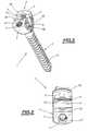
- Figure 1 is a front view, on an enlarged scale,of a pedicle screw intendedfor instrumentation for supporting the spine.
- Figure 2 is a perspective view, on an enlargedscale, of the pedicle screw in Figure 1.
- Figure 3 is a top view of the head of the screwin Figures 1 and 2.
- Figure 4 is a view, in a horizontal plane, oftwo pedicle screws anchored in a vertebra.
- Figure 5 is a front view of a pair of bonescrews joined via atransverse connection device.
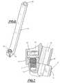
- Figure 6 is a perspective view of an instrumentwhich can advantageously be used in combination with apedicle screw.
- Figure 7 is a partial longitudinal section, onan enlarged scale, of the head of a pedicle screwand of the lower end of the instrument inFigure 6, positioned on the head of the screw.
- Figure 8 is a partial front view of two bonescrews which can be used in a spinal instrumentation.
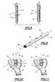
- Figure 9 is a perspective view of a support rodfor spinal instrumentation.
- Figures 10 and 11 are front views in partialsection showing the head of a screw according toFigures 1 to 3 associated with a support rod accordingto Figure 9, arranged in a first orientation in Figure10 and in a second orientation in Figure 11.
- Figure 12 is a front view of spinalosteosynthesis instrumentation.
- Figure 13 is a partial perspective view, on anenlarged scale, of an embodiment ofa screw according to the present inventionand of its means for blocking thesupport rod.
- Figure 14 is a partial side view of the screwin Figure 13.
- Figure 15 is a longitudinal section of themeans for blocking the rod associated with the screw inFigures 13 and 14.
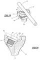
- Figure 16 is a partial perspective view, on anenlarged scale, of a different embodiment of the screw inFigures 1 to 3 and of its means for blocking the rod.
- Figure 17 is a partial section of the screw inFigure 16.
- Figure 18 is a longitudinal section of themeans for blocking the screw in Figures 16 and 17.
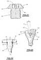
- Figure 19 is a partial perspective view, on anenlarged scale, of a second embodiment ofa screw according to the present inventionand of its means for blocking thesupport rod.
- Figure 20 is a partial section of the screw inFigure 19.
- Figure 21 is a longitudinal section of theblocking means on the screw in Figures 19 and 20.
- Figure 22 is a front view of the screw alongthe arrow K in Figure 19.
- Figure 23 is a side view of a bone-anchoringhook.
- The embodiments illustrated in figures 1-12, 16-18 and 23 do not fallwithin the scope of the present invention, as defined by the appendedclaims.
- The
pedicle screw 1 represented in Figures 1 to3 is intended to form part of instrumentation forsupporting the spine. This instrumentation has at leastone support rod dimensioned to extend along at leasttwo vertebrae and at least two pedicle screws for boneanchoring, such aspedicle screw 1. Screw 1 has a threadedrod 2 provided with abone thread 3 and a longitudinal axis X-X, and ahead 4in which there is achannel 5 having a U-shaped crosssection and a longitudinal axial plane P. Thechannel 5, delimited by twoflanks head 4, isadapted to receive a generally cylindrical support rodand for this purpose preferably has abottom 8 ofcircular cross section. On itswalls 9 there arethreadedparts 10 intended to receive a screw (notshown) for blocking a support rod (not shown). This rodcan be smooth or have a roughened surface or it can bethe type ofrod 36 which will be described below.- The U-shaped
channel 5 is formed such that itslongitudinal axial plane P is inclined by an angle Adifferent from zero degrees relative to thelongitudinal axis X-X of threadedrod 2. Thus, therectilinear walls 9, which delimit either side ofthreadedparts 10 andchannel 5 with itscircularbottom 8, have an inclination A relative to the axis X-X. - This inclination A can have a valuepreferentially up to about 65 degrees (cf. Fig. 19-20)in either direction.
- The
flanks channel 5 may have differentrespective widths hole 11 is formed intheflank 7 whosewidth 12 is the greater. Thishole 11is intended to receive a threaded member such as ascrew 12 (Figure 7) for fixing a piece to thescrew 1,for example an instrument 13 (Figures 6 - 7). Instrument 13 has a general tubular shape withan angledlower end 14 in which there is anorifice 15for introducing thescrew 12 into the threadedhole 11.Also arranged in theinstrument 13 is anaxial bore 16which is open to each end ofinstrument 13, theangledend 14 being adapted to be applied on the end faces ofthebranches screw 12 can be screwedinto thehole 11, in such a way that thebore 16 iscoaxial with the threaded parts 10 (Figure 3). Thegeometry of thehead 4 of thescrew 1 thus makes itpossible to position theinstrument 13 in such a waythat a tool can be introduced axially into thebore 16,precisely and with ease into the axis of thechannel 5,in order to easily carry out the screwing therein of athreaded plug for blocking the support rod passingthrough thechannel 5.- Figure 4 shows a
screw 1screwed into a pedicle ofa vertebra V and also ascrew 17, according to theprior art, screwed into the other pedicle of the samevertebra. To permit positioning of the screws, thesurgeon has first made an incision I in the spine bythe posterior approach, this incision I being delimitedlaterally by muscle tissues M. Thescrew 17 accordingto the prior art includes ahead 18 which is integralwith a threadedrod 19 and has aU-shaped channel 21whose axial plane contains the longitudinal axis of therod 19. Theflanks 22 delimiting thechannel 21 arethus similar in their dimensions and are symmetrical in relation to this axial plane and to the axis of therod 19. As thescrew 17 is also inclined in the pedicle inthe direction of the adjacent tissues M, the result isthat atool 23 for screwing in the plug for blockingthe support rod in thechannel 21, necessarily placedin the axis of thechannel 21, will interfere in anundesirable manner with the muscle tissues M. - By contrast, by virtue of the inclination ofthe
channel 5 relative to the axis X-X of thescrew 1,thescrewing tool 23 can beintroduced into thechannel 5 without coming intocontact with the tissues M. - Figure 5 illustrates the use of a
transverseconnection device 24 by virtue of the design of thewider flank 7 of thescrew 1. The end face of thiswideflank 7 is made up of afirst plane part 25, situatedin the plane of theplane face 26 forming the end oftheflank 6, and of asecond plane part 27 forming anobtuse angle with the plane part 25 (Figure 1). Thetransverse connection device 24 is made up of aplate 28 whose ends bear on theplane part 27 of twoscrews 1, and of twomembers 29 for blocking theplate 28 onthescrews 1. Eachmember 29 includes a threaded rod(not visible in Figure 5) passing through acorresponding orifice of theplate 28 and being screwedinto the associated threadedhole 11. - Figure 8 shows two
pedicle screws core 33 of diameter d,equipped with arespective thread core 33 is identical forboth thescrews respective threads cylindrical core 33whose diameter is constant for all the screws, whilethe external diameters d1, d2 of theirrespectivethreads screw 17 shown in Figure4, or can be according to the invention, such as thescrew 1. - The identically
rigid screws core 33 is of course chosen so that allthe screws used in the spinal instrumentation inquestion have a sufficient mechanical strength, whilethe height of their thread varies from one screw to theother. In other words, the diameter of thecore 33 ofthe screw remains identical from one screw to theother, irrespective of the external diameter of itsthread. - Figures 9 to 11 illustrate another examplein which a
pedicle screw 1 isassociated with asupport rod 36 on which at least onelongitudinal flat 37 is formed over at least part ofthe length of therod 36, the remainingpart 38 ofwhich is cylindrical. In the example illustrated inFigures 9 to 11, twolongitudinal flats 37 are arrangedon therod 36 and positioned diametrically oppositeeach other over part of the length of the rod. Inaddition, theseflats 37 are identical, that is to saythey are symmetrical with respect to the longitudinalaxis Y-Y of therod 37. For this reason, the latterhas, in the longitudinal axial plane P of thechannel 5 of thehead 4, a different flexural strength dependingon its orientation in thischannel 5. More precisely,the flat orflats 37 can extend either perpendicular tothe said axial longitudinal plane P of the channel 5(Figure 10) or parallel to it (Figure 11). Between theflats 37, therod 36 has two diametricallyoppositeparts 39 with contours of circular cross section. - The
rounded bottom 8 of thechannel 5 has aradius of curvature substantially equal to the radiusof curvature of thecircular parts 39. For this reason,when therod 36 is positioned in such a way that itsflats 37 are parallel to the axial plane P (Figure 11),one of thecircular contours 39 will bear on thecircular bottom 8 by fitting it. Advantageously, themeans for blocking therod 36 in thechannel 5, formedfor example by a threadedplug 40, has a bearing facewhich comes into contact with therod 36. - When the
rod 36 is oriented with itsflats 37perpendicular to the axial plane P of the channel 5(Figure 10), its oppositecircular contours 39 bear onrounded shoulders 43 which connect the bottom 8 to theplane walls of thechannel 5 and whose radius ofcurvature is substantially equal to that of thecircular contours 39. In this case, the plane end faceof theplug 40 is applied tightly on one of theflats 37. - The arrangement of one or two flats such as 37over at least part of the length of the
support rod 36thus makes it possible to vary its flexural strength inthe axial plane P of thechannel 5, depending on itsorientation: when theflats 37 are perpendicular to theaxial plane P (Figure 10), its flexural strength inthis plane is minimal, whereas when theseflats 37 areplaced parallel to the axial plane P (Figure 11), its flexural strength is much greater. For this reason, thebreaks which could occur hitherto with entirelycylindrical rods can be reduced by using a rod with agreater diameter and with a flat or flats, such as 36,suitably oriented in thechannel 5. - The flat or flats make it possible to adapt the"stiffness" of the assembly to the pathology of thepatient, by varying the orientation of the rod 37(Figures 10 and 11).
- By way of indicative and nonlimiting numericalexample, for a rod having a diameter of 4 mm, the
flats 37 can be separated by a distance of 3 mm. In apossible alternative, theflanks screw 1can have equal widths. Similarly, the function of thethreadedhole 11 can be provided by a threadedextension in the same location or by a geometry on thesides such asholes 60 or grooves 107 (Figures 19 and22), making it possible to grip the screw via aninstrument. - Figure 12 illustrates instrumentationused in conjunction with prior artscrews 52, including two cylindrical
vertebral rods 50extending along a segment of the spine comprising fourvertebrae 51. These rods are also equipped withpediclescrews 1, which are equipped with threadedplugs 53 forblocking therods 50, and also, at the ends of the saidrods, with bone-anchoring hooks 52 also provided withthreaded plugs 53. - The pairs of
screws 1 are connected bytransverse connection devices 24. - Of course, the
cylindrical rods 50 can bereplaced byrods 36 withflats 37, and theplugs 53 canbe replaced byplugs - Figures 13 to 15 illustrate a first embodimentof a screw according to the present invention.In this embodiment, the
screw 61 includes ahead 62 consisting of twoflanks channel 65 of U-shaped profile. Formed on one side ofthebody 62 there is also ahole 66 for gripping thescrew via an instrument (not shown). The means forblocking thesupport rod 50 is a threadedplug 67provided with acollar 68 which radially delimits twothreadedparts channel 65, namely in thewider flank 63, a threadedhole 71 is formed which has aninterruption 72 on its part contiguous with thechannel 65, so as to communicate laterally with the latter. Inthis way, after theplug 67 has been screwed into thehole 71, thecollar 68 comes into blocking engagementon therod 50 placed in thechannel 65. Theupperthread 41 projecting above thecollar 68 can be joinedto a transverse connection plate, such as 24 (Figure12), to which it is fixed by a nut (not shown). - Formed in the threaded
plug 67 there is aprofiledimpression 73 for receiving a correspondingscrewing tool (not shown). It will be noted that thecollar 68 has an asymmetrical profile formed by aflank 68a, inclined in such a way as to be able to bear ontherod 50 at the end of screwing of theplug 67, and asecond flank 68b extending radially, almostperpendicular to the longitudinal axis or me plug 67. - In the example of the
screw 75 shownin Figures 16 to 18, the head of thescrew 75 consistsof a short and fairlythin flank 76 and of a secondwider flank 77 which extends beyond the height of theflank 76. These two flanks delimit achannel 78, thebottom of which has an axial plane P at a certain inclination to the longitudinal axis XX of the bone-anchoringmember 75, and theend walls - These
walls U-shaped channel 78. Formed in thewideflank 77 there is a threadedhole 82 whose lowertruncated part opens into thechannel 78 in the zonelocated between theentry walls 79 and 81 (Figure 17).In other words, the threaded wall of thehole 82 isinterrupted at its part contiguous with thechannel 78.Thescrew 75 is completed by a threadedplug 83provided with animpression 84 for screwing. Therod 50having been placed beforehand in thechannel 78, theend cone 42 of theplug 83 comes into blockingengagement on the rod 50 (Figure 16) which is thusblocked in thechannel 78 after sufficient screwing. Asin the case of theplug 67 in Figure 13, the upper partof the thread of theplug 83 can be used with atransverse connection plate (not shown) and a lockingnut. - In the second embodimentof the present invention illustrated in Figures19 to 22, the
screw 85 comprises achannel 86 receivingasupport rod 50 and delimited by twoflanks flank 88 ends in a rectilinear part which istangent to thecylindrical bottom 86a of thechannel 86. This rectilinear part is continued via aplanesurface 89 delimiting asecond flank 91, of the screwhead, greatly inclined relative to the longitudinalaxis XX of thescrew 85, in the example shown by about60°. The bottom 86a is thus connected to aplanesurface hole 92. Lateral grooves 107 are formed on the sides oftheflanks screw 85 byan instrument (not shown).- The
screw 85 is equipped with a threadedplug 93 preferably with an inverse pitch and equipped with ahead 94 consisting of a radially projecting collar. Thecollar 94 delimits anend span 95 inclined relative tothe longitudinal axis of theplug 93 and directedtowards the outside of thehole 92 when theplug 93 isscrewed into the latter (Figure 19). Thespan 95 isconnected to aradial surface 96 completing thecollar 94. A preliminary insertion of the plug is effected atthe works, the plug being delivered pre-assembled onthe screw. - To use this embodiment, the surgeon screws the
plug 93 into thehole 92, then places therod 50 in thechannel 86. Theplug 93 is screwed in by turning it inthe opposite direction to the normal direction in thecase where its pitch is inverse. After putting therod 50 into place, the surgeon proceeds to screw theplug 93 in the opposite direction to the previous one, thatis to say in the clockwise direction. By this means,theplug 93 begins to emerge from thehole 92 until itsspan 95 comes to bear on therod 50 and blocks itagainst the inner circular wall of the channel 86(Figure 19). - The
plug 63 can also be provided with a normalpitch, and in this case the rotations of this plug arereversed. - Figure 23 illustrates a bone-anchoring
member 97 consisting of a hook formed by abody 98, having alongitudinal axial plane XX, and ahead 99 delimiting aU-shaped channel 101 between twoflanks rod 50in thechannel 101. The axial plane P of thechannel 101 is inclined relative to the longitudinal axialplane XX of thebody 98 by a variable angle A, as inthe case of thescrew 1 already described. Of course,the same applies to the other screws described above(Figures 10 - 11) which can be replaced in the same wayby a hook. In general terms, the arrangement formingthe subject of the invention can be used on all typesof bone-anchoring hooks: thus, the embodiments inFigures 13 to 21 can be used on hooks.
Claims (4)
- A bolt for connecting a vertebra to a longitudinalmember, comprising:a mounting portion disposed at a first end portionof said bolt, said mounting portion having means forengaging a vertebra, said mounting portion having alongitudinal axis; anda connector portion disposed at a second endportion of said bolt; said connector portion having achannel (86) therein that is adapted to receive thelongitudinal member (50), the channel (86) having alongitudinal axial plane, said longitudinal axial planebeing oblique to said longitudinal axis of said mountingportion, the channel being defined by at least one wall(89); anda plug (67, 93) having a longitudinal axis, said(93) having a plug head (94) comprising a profiledimpression (73) for receiving a corresponding screwing tool,said plug(93) being threadably engaged into said wall (89) in thechannel of said connector portion,characterised in that saidplug (93) has a radially projecting collar (68, 94) and it is adapted for being positioned such that said collar (68,94) presses against said longitudinal member residing inthe channel when the plug head (93) is axiallydisplaced out from said wall.
- The bolt of claim 1, wherein the longitudinal axialplane is inclined relative to the longitudinal axis ofsaid mounting portion by an angle having a value betweenzero and 65 degrees.
- The bolt of claim 1, wherein the means for engaginga vertebrae is male threads.
- The bolt of claim 1, wherein the means for engaginga vertebrae is a hook.
Applications Claiming Priority (5)
| Application Number | Priority Date | Filing Date | Title |
|---|---|---|---|
| FR9916492AFR2802796B1 (en) | 1999-12-24 | 1999-12-24 | INSTRUMENTATION FOR SHRINKAGE OF THE RACHIS COMPRISING SCREWS WITH INCLINED HEADS |
| FR9916492 | 1999-12-24 | ||
| FR0005655AFR2802797B1 (en) | 2000-05-03 | 2000-05-03 | INSTRUMENTATION FOR SHRINKAGE OF THE RACHIS AND SET OF SCREWS FOR THIS INSTRUMENTATION |
| FR0005655 | 2000-05-03 | ||
| PCT/IB2000/001956WO2001047425A1 (en) | 1999-12-24 | 2000-12-22 | Pedicle screws with inclined channels to hold support rods |
Publications (2)
| Publication Number | Publication Date |
|---|---|
| EP1244387A1 EP1244387A1 (en) | 2002-10-02 |
| EP1244387B1true EP1244387B1 (en) | 2005-12-14 |
Family
ID=26212375
Family Applications (1)
| Application Number | Title | Priority Date | Filing Date |
|---|---|---|---|
| EP00981564AExpired - LifetimeEP1244387B1 (en) | 1999-12-24 | 2000-12-22 | Pedicle screws with inclined channels to hold support rods |
Country Status (5)
| Country | Link |
|---|---|
| US (1) | US7303562B2 (en) |
| EP (1) | EP1244387B1 (en) |
| AU (1) | AU1879501A (en) |
| DE (1) | DE60024871T2 (en) |
| WO (1) | WO2001047425A1 (en) |
Families Citing this family (35)
| Publication number | Priority date | Publication date | Assignee | Title |
|---|---|---|---|---|
| DE10055888C1 (en) | 2000-11-10 | 2002-04-25 | Biedermann Motech Gmbh | Bone screw, has connector rod receiving part with unsymmetrically arranged end bores |
| EP1408874B1 (en)* | 2001-06-14 | 2012-08-08 | Amedica Corporation | Metal-ceramic composite articulation |
| US6974460B2 (en) | 2001-09-14 | 2005-12-13 | Stryker Spine | Biased angulation bone fixation assembly |
| DE20209025U1 (en)* | 2002-06-11 | 2002-08-14 | Dierks, Michael, 42929 Wermelskirchen | Device for holding a connecting rod of a spinal fixative |
| US20040111088A1 (en)* | 2002-12-06 | 2004-06-10 | Picetti George D. | Multi-rod bone attachment member |
| AU2003297195A1 (en)* | 2002-12-17 | 2004-07-22 | Amedica Corporation | Total disc implant |
| US7717939B2 (en) | 2004-03-31 | 2010-05-18 | Depuy Spine, Inc. | Rod attachment for head to head cross connector |
| US7645294B2 (en)* | 2004-03-31 | 2010-01-12 | Depuy Spine, Inc. | Head-to-head connector spinal fixation system |
| US7717938B2 (en) | 2004-08-27 | 2010-05-18 | Depuy Spine, Inc. | Dual rod cross connectors and inserter tools |
| US20060084978A1 (en)* | 2004-09-30 | 2006-04-20 | Mokhtar Mourad B | Spinal fixation system and method |
| US20070233062A1 (en)* | 2006-04-04 | 2007-10-04 | Amedica Corporation | Pedicle screw system with offset stabilizer rod |
| WO2007121271A2 (en) | 2006-04-11 | 2007-10-25 | Synthes (U.S.A) | Minimally invasive fixation system |
| US20080058805A1 (en)* | 2006-08-28 | 2008-03-06 | Microdexterity Systems, Inc. | Spinal fusion implant |
| US20080177327A1 (en)* | 2006-10-17 | 2008-07-24 | Hugues Malandain | Central rod connector and T-rod |
| US8361117B2 (en) | 2006-11-08 | 2013-01-29 | Depuy Spine, Inc. | Spinal cross connectors |
| US7959655B2 (en)* | 2007-03-06 | 2011-06-14 | Warsaw Orthopedic, Inc. | Self-aligning attachment devices and methods for attaching an elongated member to a vertebral member |
| WO2008128105A1 (en)* | 2007-04-12 | 2008-10-23 | Texas Scottish Rite Hospital For Children | Orthopedic fastener for stabilization and fixation |
| US8348976B2 (en) | 2007-08-27 | 2013-01-08 | Kyphon Sarl | Spinous-process implants and methods of using the same |
| WO2009097623A2 (en)* | 2008-02-02 | 2009-08-06 | Texas Scottish Rite Hospital For Children | Pedicle screw |
| US9345517B2 (en) | 2008-02-02 | 2016-05-24 | Globus Medical, Inc. | Pedicle screw having a removable rod coupling |
| US9408641B2 (en)* | 2008-02-02 | 2016-08-09 | Globus Medical, Inc. | Spinal rod link reducer |
| US9579126B2 (en)* | 2008-02-02 | 2017-02-28 | Globus Medical, Inc. | Spinal rod link reducer |
| US9504494B2 (en)* | 2008-04-28 | 2016-11-29 | DePuy Synthes Products, Inc. | Implants for securing spinal fixation elements |
| US8206421B2 (en)* | 2008-05-15 | 2012-06-26 | Warsaw Othropedic, Inc. | Methods and devices for insertion of tethers through subcutaneous screw heads |
| EP2484300B1 (en)* | 2008-09-05 | 2015-05-20 | Biedermann Technologies GmbH & Co. KG | Stabilization device for bones, in particular for the spinal column |
| US8727972B2 (en)* | 2009-02-03 | 2014-05-20 | Warsaw Orthopedic, Inc. | Low profile bone screw extender and its application in minimum invasive spinal surgeries |
| CN102497828B (en)* | 2009-05-20 | 2015-09-09 | 斯恩蒂斯有限公司 | What patient installed retracts part |
| USD642270S1 (en) | 2010-02-24 | 2011-07-26 | Globus Medical, Inc. | Rigid orthopedic screw |
| US8535318B2 (en) | 2010-04-23 | 2013-09-17 | DePuy Synthes Products, LLC | Minimally invasive instrument set, devices and related methods |
| US10603083B1 (en) | 2010-07-09 | 2020-03-31 | Theken Spine, Llc | Apparatus and method for limiting a range of angular positions of a screw |
| US9084634B1 (en) | 2010-07-09 | 2015-07-21 | Theken Spine, Llc | Uniplanar screw |
| CN103717159B (en) | 2011-05-27 | 2016-08-17 | 新特斯有限责任公司 | Minimally Invasive Spinal Fixation System Including Vertebral Alignment Features |
| CA3008161C (en) | 2014-12-09 | 2023-09-26 | John A. Heflin | Spine alignment system |
| US10507043B1 (en) | 2017-10-11 | 2019-12-17 | Seaspine Orthopedics Corporation | Collet for a polyaxial screw assembly |
| CN113317859B (en)* | 2021-06-16 | 2022-09-27 | 青岛大学附属医院 | percutaneous screw rod system |
Family Cites Families (36)
| Publication number | Priority date | Publication date | Assignee | Title |
|---|---|---|---|---|
| US1980093A (en)* | 1925-01-16 | 1934-11-06 | Rosenberg Heyman | Anchorage device |
| US4743260A (en)* | 1985-06-10 | 1988-05-10 | Burton Charles V | Method for a flexible stabilization system for a vertebral column |
| EP0209685A3 (en)* | 1985-07-12 | 1988-11-09 | Fischerwerke Arthur Fischer GmbH & Co. KG | Fixation element for osteosynthesis |
| FR2612071A1 (en) | 1987-03-13 | 1988-09-16 | Cotrel Yves | VERTEBRAL SCREW FOR OSTEOSYNTHESIS DEVICE, ESPECIALLY LUMBAR AND DORSAL |
| FR2633177B1 (en)* | 1988-06-24 | 1991-03-08 | Fabrication Materiel Orthopedi | IMPLANT FOR A SPINAL OSTEOSYNTHESIS DEVICE, ESPECIALLY IN TRAUMATOLOGY |
| FR2645732B1 (en) | 1989-04-13 | 1997-01-03 | Cotrel Yves | VERTEBRAL IMPLANT FOR OSTEOSYNTHESIS DEVICE |
| FR2658414B1 (en)* | 1990-02-19 | 1992-07-31 | Sofamor | IMPLANT FOR OSTEOSYNTHESIS DEVICE IN PARTICULAR OF THE RACHIS. |
| GB9014817D0 (en)* | 1990-07-04 | 1990-08-22 | Mehdian Seyed M H | Improvements in or relating to apparatus for use in the treatment of spinal disorders |
| US5129900B1 (en)* | 1990-07-24 | 1998-12-29 | Acromed Corp | Spinal column retaining method and apparatus |
| DE4026777A1 (en) | 1990-08-24 | 1992-03-05 | Haerle Anton | FOCUS BONE SCREW AND / OR TAP FOR OSTEOSYNTHESIS WORK |
| US5127912A (en)* | 1990-10-05 | 1992-07-07 | R. Charles Ray | Sacral implant system |
| US5176679A (en)* | 1991-09-23 | 1993-01-05 | Lin Chih I | Vertebral locking and retrieving system |
| US5382248A (en)* | 1992-09-10 | 1995-01-17 | H. D. Medical, Inc. | System and method for stabilizing bone segments |
| FR2697742B1 (en)* | 1992-11-06 | 1994-12-16 | Biomat | Osteosynthesis device for spinal consolidation. |
| US6030162A (en)* | 1998-12-18 | 2000-02-29 | Acumed, Inc. | Axial tension screw |
| US5387212A (en)* | 1993-01-26 | 1995-02-07 | Yuan; Hansen A. | Vertebral locking and retrieving system with central locking rod |
| US5466238A (en)* | 1993-08-27 | 1995-11-14 | Lin; Chih-I | Vertebral locking and retrieving system having a fixation crossbar |
| DE4342415C2 (en)* | 1993-12-13 | 1998-04-16 | Haerle Anton | Tension-optimized thread profile |
| JPH07163580A (en)* | 1993-12-15 | 1995-06-27 | Mizuho Ika Kogyo Kk | Forward correcting device for scoliosis |
| FR2719759B1 (en) | 1994-05-16 | 1996-08-30 | Charles Khalife | Intervertebral osteosynthesis system, in particular with transverse reinforcement device. |
| US5669911A (en)* | 1995-04-13 | 1997-09-23 | Fastenetix, L.L.C. | Polyaxial pedicle screw |
| US5562663A (en)* | 1995-06-07 | 1996-10-08 | Danek Medical, Inc. | Implant interconnection mechanism |
| JP2960688B2 (en)* | 1996-06-07 | 1999-10-12 | 株式会社ロバート・リード商会 | Bone fixation screw |
| US5941885A (en)* | 1996-10-08 | 1999-08-24 | Jackson; Roger P. | Tools for use in installing osteosynthesis apparatus utilizing set screw with break-off head |
| US6224596B1 (en)* | 1997-01-06 | 2001-05-01 | Roger P. Jackson | Set screw for use with osteosynthesis apparatus |
| TW382657B (en)* | 1997-06-13 | 2000-02-21 | Advantest Corp | Memory tester |
| US5868051A (en)* | 1997-08-28 | 1999-02-09 | Pakos Group | Method and apparatus for machining with a pivoting cutting tool |
| EP0933065A1 (en)* | 1998-02-02 | 1999-08-04 | Sulzer Orthopädie AG | Pivotable attachment system for a bone screw |
| DE29808593U1 (en)* | 1998-05-13 | 1999-09-23 | Howmedica GmbH, 24232 Schönkirchen | Device for connecting two spaced longitudinal rods of a spinal implant |
| US6264658B1 (en)* | 1998-07-06 | 2001-07-24 | Solco Surgical Instruments Co., Ltd. | Spine fixing apparatus |
| FR2781663B1 (en)* | 1998-07-30 | 2000-10-13 | Materiel Orthopedique En Abreg | SPINAL OSTEOSYNTHESIS DEVICE |
| WO2000015125A1 (en)* | 1998-09-11 | 2000-03-23 | Synthes Ag Chur | Variable angle spinal fixation system |
| KR100324698B1 (en)* | 1999-01-30 | 2002-02-27 | 구자교 | Spine fixing device |
| US6547789B1 (en)* | 1999-07-02 | 2003-04-15 | Sulzer Orthopedics Ltd. | Holding apparatus for the spinal column |
| US6261288B1 (en)* | 2000-02-08 | 2001-07-17 | Roger P. Jackson | Implant stabilization and locking system |
| US6488681B2 (en)* | 2001-01-05 | 2002-12-03 | Stryker Spine S.A. | Pedicle screw assembly |
- 2000
- 2000-12-22EPEP00981564Apatent/EP1244387B1/ennot_activeExpired - Lifetime
- 2000-12-22AUAU18795/01Apatent/AU1879501A/ennot_activeAbandoned
- 2000-12-22USUS10/168,135patent/US7303562B2/ennot_activeExpired - Lifetime
- 2000-12-22WOPCT/IB2000/001956patent/WO2001047425A1/enactiveIP Right Grant
- 2000-12-22DEDE60024871Tpatent/DE60024871T2/ennot_activeExpired - Fee Related
Also Published As
| Publication number | Publication date |
|---|---|
| DE60024871T2 (en) | 2006-07-27 |
| US20030144664A1 (en) | 2003-07-31 |
| DE60024871D1 (en) | 2006-01-19 |
| US7303562B2 (en) | 2007-12-04 |
| WO2001047425A1 (en) | 2001-07-05 |
| EP1244387A1 (en) | 2002-10-02 |
| AU1879501A (en) | 2001-07-09 |
Similar Documents
| Publication | Publication Date | Title |
|---|---|---|
| EP1244387B1 (en) | Pedicle screws with inclined channels to hold support rods | |
| US5290288A (en) | Multi-function device for the osteosynthesis of rachis | |
| US11389207B2 (en) | Bottom loaded bone screw assembly with direct pivotal engagement between screw head and body member | |
| US5067955A (en) | Vertebral implant for osteosynthesis device | |
| EP1304967B1 (en) | Spinal fixation system | |
| EP2153786B1 (en) | Modular system for the stabilization of the spinal column | |
| US7264621B2 (en) | Multi-axial bone attachment assembly | |
| US6749361B2 (en) | Shackle element for clamping a fixation rod, a method for making a shackle element, a hook with a shackle element and a rode connector with a shackle element | |
| KR101325250B1 (en) | Locking assembly for securing a rod member in a receiver part for use in spinal or trauma surgery, bone anchoring device with such a locking assembly and tool therefor | |
| US5476463A (en) | Spinal column retaining apparatus | |
| KR100996240B1 (en) | Fixing member | |
| US6027533A (en) | Device for fixating and adjusting the positions of vertebrae in vertebral surgical operations | |
| JP4414889B2 (en) | Cross connector assembly for interconnecting a pair of orthopedic rods | |
| AU753598B2 (en) | Device for securing spinal rods | |
| EP1317215B1 (en) | Posterior fixation system | |
| US20110282388A1 (en) | Multi Axial Cross Link Connector System for Spinal Implants | |
| AU2001260001A1 (en) | Spinal fixation system | |
| US20020143327A1 (en) | Transverse connector for use in spinal corrective surgery | |
| WO2001067974A1 (en) | Multi-axial bone anchor system | |
| CA2603514A1 (en) | Anti-backout mechanism for an implant fastener | |
| US20060079893A1 (en) | Threadform for medical implant closure | |
| EP3893777B1 (en) | Bone anchor head extender | |
| EP3730078B1 (en) | Closure assembly for securing a stabilization element in a receiving part of a bone anchoring device | |
| KR101277740B1 (en) | Dual anchor spinal implant apparatus | |
| EP0888754A1 (en) | Osteosynthetic Fastener |
Legal Events
| Date | Code | Title | Description |
|---|---|---|---|
| PUAI | Public reference made under article 153(3) epc to a published international application that has entered the european phase | Free format text:ORIGINAL CODE: 0009012 | |
| 17P | Request for examination filed | Effective date:20020724 | |
| AK | Designated contracting states | Kind code of ref document:A1 Designated state(s):AT BE CH CY DE DK ES FI FR GB GR IE IT LI LU MC NL PT SE TR | |
| AX | Request for extension of the european patent | Free format text:AL;LT;LV;MK;RO;SI | |
| 17Q | First examination report despatched | Effective date:20040130 | |
| RBV | Designated contracting states (corrected) | Designated state(s):DE | |
| GRAP | Despatch of communication of intention to grant a patent | Free format text:ORIGINAL CODE: EPIDOSNIGR1 | |
| RIN1 | Information on inventor provided before grant (corrected) | Inventor name:HUTEN, DENIS Inventor name:MALANDAIN, HUGUES Inventor name:CAVAGNA, REMI Inventor name:GOURNAY, JOSE | |
| GRAS | Grant fee paid | Free format text:ORIGINAL CODE: EPIDOSNIGR3 | |
| GRAA | (expected) grant | Free format text:ORIGINAL CODE: 0009210 | |
| AK | Designated contracting states | Kind code of ref document:B1 Designated state(s):DE | |
| RIN1 | Information on inventor provided before grant (corrected) | Inventor name:CAVAGNA, REMI Inventor name:GOURNAY, JOSE Inventor name:HUTEN, DENIS Inventor name:MALANDAIN, HUGUES | |
| REF | Corresponds to: | Ref document number:60024871 Country of ref document:DE Date of ref document:20060119 Kind code of ref document:P | |
| PLBE | No opposition filed within time limit | Free format text:ORIGINAL CODE: 0009261 | |
| STAA | Information on the status of an ep patent application or granted ep patent | Free format text:STATUS: NO OPPOSITION FILED WITHIN TIME LIMIT | |
| 26N | No opposition filed | Effective date:20060915 | |
| PGFP | Annual fee paid to national office [announced via postgrant information from national office to epo] | Ref country code:DE Payment date:20081230 Year of fee payment:9 | |
| PG25 | Lapsed in a contracting state [announced via postgrant information from national office to epo] | Ref country code:DE Free format text:LAPSE BECAUSE OF NON-PAYMENT OF DUE FEES Effective date:20100701 |