EP1244028B1 - Method, computer program product and computer system for a single database system to support multiple application systems - Google Patents
Method, computer program product and computer system for a single database system to support multiple application systemsDownload PDFInfo
- Publication number
- EP1244028B1 EP1244028B1EP01126777AEP01126777AEP1244028B1EP 1244028 B1EP1244028 B1EP 1244028B1EP 01126777 AEP01126777 AEP 01126777AEP 01126777 AEP01126777 AEP 01126777AEP 1244028 B1EP1244028 B1EP 1244028B1
- Authority
- EP
- European Patent Office
- Prior art keywords
- application
- database
- memory
- profile
- database system
- Prior art date
- Legal status (The legal status is an assumption and is not a legal conclusion. Google has not performed a legal analysis and makes no representation as to the accuracy of the status listed.)
- Expired - Lifetime
Links
Images


Classifications
- G—PHYSICS
- G06—COMPUTING OR CALCULATING; COUNTING
- G06F—ELECTRIC DIGITAL DATA PROCESSING
- G06F16/00—Information retrieval; Database structures therefor; File system structures therefor
- G06F16/20—Information retrieval; Database structures therefor; File system structures therefor of structured data, e.g. relational data
- G06F16/25—Integrating or interfacing systems involving database management systems
- G06F16/252—Integrating or interfacing systems involving database management systems between a Database Management System and a front-end application
- Y—GENERAL TAGGING OF NEW TECHNOLOGICAL DEVELOPMENTS; GENERAL TAGGING OF CROSS-SECTIONAL TECHNOLOGIES SPANNING OVER SEVERAL SECTIONS OF THE IPC; TECHNICAL SUBJECTS COVERED BY FORMER USPC CROSS-REFERENCE ART COLLECTIONS [XRACs] AND DIGESTS
- Y10—TECHNICAL SUBJECTS COVERED BY FORMER USPC
- Y10S—TECHNICAL SUBJECTS COVERED BY FORMER USPC CROSS-REFERENCE ART COLLECTIONS [XRACs] AND DIGESTS
- Y10S707/00—Data processing: database and file management or data structures
- Y10S707/99931—Database or file accessing
- Y10S707/99932—Access augmentation or optimizing
Definitions
- the present inventiongenerally relates to database systems for application systems, and more particularly, relates to methods, computer program products and systems for improving the efficiency of database management in a multi-application system landscape.
- ERPEnterprise Resource Planning
- Client-server technologythat was first introduced by the SAP R/3 ERP software became the de facto industry standard for business application software.
- Client-server technologyseparates the client (front end) from the application server that is running the application software. Further, the application server is separated from a database server that is running the database software.
- the databaseholds all data that are relevant to the application software.
- the high scalability of this multi-tier approachallowed huge numbers of users in an organization to work simultaneously in the same application system because the load of the system could be better balanced between application servers and database servers compared to systems where applications were run on the data base server.
- CRMCustomer Relationship Management
- SCMSupply Chain Management
- the typical landscape of todayconsists of distributed systems with different software applications and separate servers. Each system requires its own database on its own physical hardware. The reasons for this are hardware and software related. For example, most symmetric multiprocessor (SMP) systems were limited to less than 16 processors and less than 4 GB of shared main memory. Operating systems did not offer the feature of creating multiple logical partitions for groups of processors. Databases only allowed for a maximum number of manageable tables (e.g. 10000).
- SMPsymmetric multiprocessor
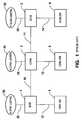
- FIG.1illustrates an example of an organization's computer system landscape of the prior art.
- the application systems ERP 1, CRM 2 and SCM 3are connected through a network.
- the networkis a local area network (LAN) or a wide area network or any other network known in the art and comprises the branches 10 and 11.
- Each of the application systemsrequires its own database system (DB) with the corresponding application data, for example, ERP DB 4, CRM DB 5 and SCM DB 6.
- Each database system 4-6is connected to the corresponding application system 1-3 via network branches 12-14.
- Each application system 1-3provides application services to pluralities 20-22 of application users. Multiple application users of each of the pluralities can be assigned to a single person.
- All application users of the pluralitiescan connect 23-25 to the corresponding application system 1-3 through, for example, a browser based front end computer (not shown) via the network.
- the system of the prior arttherefore, implies the need of providing three database server computers as well as the need of administrating (backup, tune, manage) these three different database systems.
- Document WO 99/12099 A1discloses a method for allocating physical memory locations in a multiprocessor data processing treatment system comprising a memory unit with non-uniformity access distributed among several modules.
- Document US 5,898,883discloses a memory access mechanism for a parallel processing computer system with distributed shared memory, wherein a variable-length Global/Local allocation field is provided in a fixed-length address.
- the subject-matter of the present applicationallows different application systems access to the same information.
- the present inventionprovides system, method and computer program product for providing multiple business software applications to users with significantly less hardware and less system administration effort by running multiple, independent and different software applications in connection with a single database system. Only one physical database server is needed for n applications, whereas in the prior art systems n physical database servers were required. Therefore, only one database system has to be administrated (e.g. daily backup, database tuning, security administration). Thus, the present invention lowers the cost of ownership for the application systems of an organization.
- database systemis intended to comprise
- Storing meansare, for example, tables or areas.
- a retrieving meansis, for example, a database operating system.
- Database systemsare commercially available. Database systems are sometimes referred to as “database management systems” (DBMS).
- DBMSdatabase management systems
- the database systemis a relational database system.
- application systems and database systemscommunicate by predefined statements in a predefined database description language.
- a predefined database description languageis well known in the art: an example is the structured query language (SQL).
- the technical restrictions leading to the multi-database system paradigm in the prior arthave been resolved.
- the present inventiontakes advantage of a high performance database system having the following characteristics:
- the present inventionsolves the technical problem that one database system of the prior art was not able to store application data of multiple application systems that use the database system simultaneously.
- the computer system described in claim 1, and the method described in claim 7allow multiple application systems to use the same physical database system simultaneously. This is achieved through the ability of the data base system to support multiple profiles (different types of database users) where each profile is assigned to an application system. Each application becomes the owner of a memory portion of the database system memory, through the assigned profile. All memory portions of the database system are disjunctive and, therefore, consistently hold all application related data from the different application systems.
- a further advantage of the single database architecture of the present inventionis the possibility of upgrading an application system without the interruption of running applications of other application systems that use the same data base system. For example, a person of skill in the art can achieve this by replicating the shared program parts of the database software to each database profile.
- the present inventionsolves the technical problem that, in the prior art, a full, consistent point-in-time recovery of multiple application systems in a network was not possible in case of a total of partial break-down of these systems.
- all application systemsuse the same database system. This guarantees the integrity of all application data stored in this database system.
- a backupcan be performed on-line by continuously writing deltas of the application data to a backup database system, or it can be performed off-line as a system copy when the database system is down.
- the on-line backupis used for the consistent point-in-time recovery, whereas the off-line backup can be used as a basis for further system implementations within an organization.
- the present inventionprovides a solution to the technical problem of inadequate load balance of the database system caused by simultaneous access of multiple application systems. Improving the load balance is achieved by using multiple application systems in combination with a single database system, where the database system uses an operating system, which comprises the feature of creating multiple logical groups of processors in a SMP system. Therefore, groups of processors of the database server computer can be assigned to each application system. For example, when the highest database load originates from an ERP system, followed by the load from an CRM and an SCM system, a possible configuration would be to assign 24 processors to the ERP system, 16 processors to the CRM system and only 8 processors to the SCM system, if the database server uses shared memory processors (SMP) and comprises at least 48 processors.
- SMPshared memory processors
- a person of skill in the artcan further increase the scalability of the database system through the usage of parallel database servers, by blending separate machines into a single large virtual database server with a shared cache memory.
- FIG. 2illustrates a preferred embodiment of computer system 999 with multiple application computer systems (901, 902) operating on the same database computer system (900) according to the present invention.
- Computers 900-902are coupled via inter-computer network 990.
- Database computer 900comprises processor 910, memory 920, bus 930, and, optionally, input device 940 and output device 950 (I/O devices, user interface 960).
- the inventionis present by computer program product 100 (CPP), program carrier 970 and program signal 980, collectively "program”.
- computer 901/902is sometimes referred to as "remote computer", computer 901/902 is, for example, a server, a router, a peer device or other common network node, and typically comprises many or all of the elements described relative to computer 900.
- Computer 900is, for example, a conventional database server computer in the form of a multiprocessor computer, a mainframe computer, a portable or stationary personal computer, or the like.
- Processor 910stands for at least one processor, such as, a central processing unit (CPU), a micro-controller unit (MCU), digital signal processor (DSP), or the like.
- CPUcentral processing unit
- MCUmicro-controller unit
- DSPdigital signal processor
- Memory 920symbolizes elements that temporarily or permanently store data and instructions. Although memory 920 is conveniently illustrated as part of computer 900, memory function can also be implemented in network 990, in computers 901/902 and in processor 910 itself (e.g., cache, register), or elsewhere. Memory 920 can be a read only memory (ROM), a random access memory (RAM), or a memory with other access options.
- ROMread only memory
- RAMrandom access memory
- Memory 920is physically implemented by computer-readable media, such as, for example: (a) magnetic media, such as, for example, a hard disk, a floppy disk, or other magnetic disk, a tape, a cassette tape; (b) optical media, such as, for example, optical disk (CD-ROM, digital versatile disk - DVD); (c) semiconductor media, such as, for example, DRAM, SRAM, EPROM, EEPROM, memory stick, or by any other media, such as, for example, paper.
- computer-readable mediasuch as, for example: (a) magnetic media, such as, for example, a hard disk, a floppy disk, or other magnetic disk, a tape, a cassette tape; (b) optical media, such as, for example, optical disk (CD-ROM, digital versatile disk - DVD); (c) semiconductor media, such as, for example, DRAM, SRAM, EPROM, EEPROM, memory stick, or by any other media, such as, for example, paper.
- memory 920is distributed across different media. Portions of memory 920 can be removable or non-removable.
- computer 900uses devices well known in the art such as, for example, disk drives, tape drives.
- Memory 920stores support modules such as, for example, a basic input output system (BIOS), an operating system (OS), a program library, a compiler, an interpreter, and a text- processing tool.
- support modulesare commercially available and can be installed on computer 900 by those of skill in the art. For simplicity, these modules are not illustrated.
- CPP 100comprises program instructions and - optionally - data that cause processor 910 to execute method steps 430 to 450 of the present invention. Method steps are explained with more detail below.
- CPP 100defines the operation of computer 900 and its interaction in system network system 999.
- CPP 100can be available as source code in any programming language, and as object code ("binary code") in a compiled form. Persons of skill in the art can use CPP 100 in connection with any of the above support modules (e.g., compiler, interpreter, operating system).
- CPP 100is illustrated as being stored in memory 920, CPP 100 can be located elsewhere. CPP 100 can also be embodied in carrier 970.
- Carrier 970is illustrated outside computer 900. For communicating CPP 100 to computer 900, carrier 970 is conveniently inserted into input device 940. Carrier 970 is implemented as any computer readable medium, such as a medium largely explained above (cf. memory 920). Generally, carrier 970 is an article of manufacture comprising a computer readable medium having computer readable program code means embodied therein for executing the method of the present invention. Further, program signal 980 can also embody computer program 100. Signal 980 travels on network 990 to computer 900.
- program carrier 970Having described CPP 100, program carrier 970, and program signal 980 in connection with computer 900 is convenient.
- program carrier 971/972(not shown) and program signal 981/982 embody computer program product (CPP) 101/102 to be executed by processor 911/912 (not shown) in computers 901/902, respectively.
- processor 911/912(not shown) in computers 901/902, respectively.
- Input device 940symbolizes a device that provides data and instructions for processing by computer 900.
- device 940is a keyboard, a pointing device (e.g., mouse, trackball, cursor direction keys), microphone, joystick, game pad, scanner.
- a wireless receivere.g., with satellite dish or terrestrial antenna
- a sensore.g., a thermometer
- a countere.g., goods counter in a factory.
- Input device 940can serve to read carrier 970.
- Output device 950symbolizes a device that presents instructions and data that have been processed.
- a monitor or other type of display(cathode ray tube (CRT), flat panel display, liquid crystal display (LCD), a speaker, a printer, a plotter, a vibration alert device.
- output device 950communicates with the user, but it can also communicate with further computers.
- Input device 940 and output device 950can be combined to a single device; any device 940 and 950 can be provided optional.
- Bus 930 and network 990provide logical and physical connections by conveying instruction and data signals. While connections inside computer 900 are conveniently referred to as “bus 930", connections between computers 900-902 are referred to as “network 990". Devices 940 and 950 are coupled to computer 900 by bus 930 (as illustrated) or by network 990 (optional). While the signals inside computer 900 are mostly electrical signals, the signals in network are electrical, magnetic, optical or wireless (radio) signals.
- Networking environmentsare commonplace in offices, enterprise-wide computer networks, intranets and the Internet (i.e. world wide web). The physical distance between a remote computer and computer 900 is not important.
- Network 990can be a wired or a wireless network.
- network 990is, for example, a local area network (LAN), a wide area network (WAN), a public switched telephone network (PSTN); a Integrated Services Digital Network (ISDN), an infra-red (IR) link, a radio link, like Universal Mobile Telecommunications System (UMTS), Global System for Mobile Communication (GSM), Code Division Multiple Access (CDMA), or satellite link.
- LANlocal area network
- WANwide area network
- PSTNpublic switched telephone network
- ISDNIntegrated Services Digital Network
- IRinfra-red
- radio linklike Universal Mobile Telecommunications System (UMTS), Global System for Mobile Communication (GSM), Code Division Multiple Access (CDMA), or satellite link.
- UMTSUniversal Mobile Telecommunications System
- GSMGlobal System for
- Transmission protocols and data formatsare know, for example, as transmission control protocol/internet protocol (TCP/IP), hyper text transfer protocol (HTTP), secure HTTP, wireless application protocol, unique resource locator (URL), a unique resource identifier (URI), hyper text markup language HTML, extensible markup language (XML), extensible hyper text markup language (XHTML), wireless application markup language (WML), etc.
- TCP/IPtransmission control protocol/internet protocol
- HTTPhyper text transfer protocol
- HTTPsecure HTTP
- wireless application protocolunique resource locator
- URLunique resource locator
- URIunique resource identifier
- HTMLhyper text markup language
- XMLextensible markup language
- XHTMLextensible hyper text markup language
- WMLwireless application markup language
- An interfacecan be, for example, a serial port interface, a parallel port interface, a game port, a universal serial bus (USB) interface, an internal or external modem, a video adapter, or a sound card.
- USBuniversal serial bus
- FIG. 3illustrates a detailed view of the preferred embodiment of computer system 999.
- Computer system 999comprises at least first application system 901 and second application system 902 as well as database system 900.
- First application system 901is running at least one application service out of plurality 201 of application services (labeled AS1)
- second application system 902is running at least one application service out of plurality 301 of application services (labeled AS2).
- At least one user out of a first plurality of application users 801can use application services from AS1 by connecting to first application system 901 via at least one front end computer (not shown).
- the front end computercan be, for example, a PC, a laptop computer, a web server or the like.
- At least one user out of a second plurality of application users 802can use application services from AS2 by connecting to second application system 902 via at least one front end computer (not shown).
- the connections 990-1 from plurality 801 to first application system 901 and 990-2 from plurality 802 to second application system 902are illustrated as part of network 990 and stand for connections to the front end computers (not shown).
- An application usercan use the same front-end computer to access both application systems (901, 902). It is not necessary for the invention that each application user corresponds to a different person, rather one person can be assigned to multiple application users of multiple application systems.
- memory 920 of database system 900has at least a first memory portion 920-1 and a second memory portion 920-2.
- the memory portionsare disjunctive. That is, changes in first memory portion 920-1 have no impact on second memory portion 920-2 and vice versa.
- Database system 900stores at least a first assignment of first predetermined profile 110 to first memory portion 920-1 and stores at least a second assignment of second predetermined profile 111 to second memory portion 920-2.
- first profile 110 and second profile 111each is unique and refers to first and second application systems (901, 902), respectively. This reference is illustrated by dashed lines 110-1 and 111-1.
- the application systemWhen an application user launches an application service in one of the application systems 901 or 902, the application system (that is executing the service) accesses database system 900.
- first application system 901accesses first memory portion 920-1 of database system 900 through profile 110.
- second application system 902accesses second memory portion 920-2 of the same database system 900 through profile 111.
- profiles 110 and 111can be considered as users of database system 900, where the database user is the application system (901, 902) that refers (110-1, 111-1) to the corresponding profile (110, 111).
- This architectureroutes a large number of application users through one profile to database system 900, thus keeping the load of the database system low. It is not necessary for the invention that only one profile is assigned to each application system.
- the load of the database systemis increased compared to the load of the application systems - especially when running multiple application systems in connection with the same database system.
- one application systemcan comprise multiple application server computers to balance the load on multiple processors. Therefore, the application system scales with additional hardware that is added to the system.
- FIG. 4illustrates database tables 190-193 in memory 920 of database system 900 according to the present invention.
- Tables 190, 191are stored in first memory portion 920-1 and tables 192, 193 are stored in second memory portion 920-2.
- Profiles 110 and 111are assigned to memory portions 920-1 and 920-2, respectively. This indicates that only first application system 901 can access first memory portion 920-1 and only second application system 902 can access second memory portion 920-2.
- Each tablecomprises in its table header the information about the profiles (and therefore, indirectly about the application systems) that can access the table. Sometimes, different application systems need access to the same information.
- the material master data table of the ERP systemis consistent with the material master data table of the SCM system.
- the different memory portions (e.g. 920-1, 920-2) of database system 900are disjunctive.
- the memory portion with the profile for the ERP systemdoes not allow the SCM system to access its material master data table. Therefore, some tables exist in more than one memory portion of the database system. The data consistency of these tables is guaranteed by each application system through network 990 communication (cf. FIG. 3 ) with another application system and each system consistently updating its own tables in the corresponding memory portion.
- FIG. 5illustrates a simplified flow chart of method 400 for multiple application systems to communicate with a single data base system.
- Method 400comprises the steps providing application systems 410, connecting database system with application systems 420, dividing database memory into disjunctive memory portions 430, assigning memory portions to application systems 440 and accessing memory portions by application systems 450.
- step 410at least a first application system 901 (cf. FIG. 3 ) and a second application system 902 are provided.
- Each of the application systemsruns at least one application service out of a plurality of application services (201, 301) for a plurality of users (801, 802) of the application system (901, 902).
- step 420database system 900 gets connected with at least first application system 901 and second application system 902. The connection is established via network 990.
- step 430memory 920 of data base system 900 is logically divided into at least a first memory portion 920-1 and a second memory portion 920-2.
- the memory portionsare disjunctive.
- Memory portions 920-1 and 920-2store tables 190-193 (cf. FIG. 4 ) of the database system 900.
- first memory portion 920-1is assigned to application system 901 and second memory portion 920-2 is assigned to second application system 902.
- the assignments from memory portion to application systemare implemented as described in the following: a) At least one predefined, unique profile 110, 111 of database system 900 is assigned to each memory portion 920-1, 920-2.
- the assignmentscan be stored in "memory portion to profile assignment" database matrices, such as matrix 1 (cf. FIG. 6 ).
- Matrix 1memory portion to profile assignment Memory portion Profile 920-1 110 920-1 ... 920-2 111 b)
- At least one of the predefined profiles 110, 111 of each memory portion 920-1, 920-2is assigned to the corresponding application system 901, 902, respectively.
- the assignmentscan be stored in a "profile to application system assignment" database matrix, such as matrix 2 (cf. FIG. 6 ).
- Matrix 2Profile to application system assignment Application System Profile 901 110 901 ... 902 111
- first and second application systems (901, 902)access first and second memory portions (920-1, 920-2), respectively.
- application systems 901, 902access database system 900 through at least one of their assigned profiles 110, 111.
- the application system accessing the database systemtriggers any of the database table operations, such as, read, write, copy, modify, insert, append and delete table entries, within the memory portion that is assigned to the application system.
- a person of skill in the artcan implement profiles 110 and 111 and the assignments of matrices 1 and 2 by using database buffers so that the logical assignment of each application system to the corresponding memory portion remains valid while system 999 is running. Therefore, the assignment has not to be newly established with every access of an application system to the database system.
- FIG. 6illustrates a simplified block diagram of the application systems 901 and 902 and database system 900 with assignment matrices 180, 181 and 182.
- Matrices 180, 181 and 182implement the storage of the assignments explained above in connection with matrices 1 and 2.
- matrix 180stores the memory portion to profile assignment (cf. matrix 1); matrix 181 stores the profile to application system assignment for system 901 (cf. matrix 2); and matrix 182 stores the profile to application assignment for system 902 (cf. matrix 2).
- matrices 180-182are not essential for the present invention; conveniently, matrices 180-182 are located as illustrated in FIG. 6 .
- Matrix 180is stored in memory 920 of system 900; matrix 181 is stored in memory 921 of system 901; matrix 182 is stored in memory 922 of system 902.
- Persons of skill in the artcan locate the matrices at other locations, provided compliance with the above explained function.
- matrices 181-183are part of computer program product 100/101/102, respectively.
- FIG. 7illustrates a specific, preferred embodiment of the present invention by using application systems 904-909 of the SAP product family and database system 903, such as an ORACLE8i system.
- Two R/3 ERP systems 904/905, one CRM system 906, one SCM system 907, one Workplace (WP) systems 908 and one Knowledge Warehouse (KW) 909are connected via network 995 to database system 903.
- Memory 923 of database system 903is divided into 6 disjunctive memory portions 923-1 to 923-6.
- Profiles P1-P6are assigned to memory portions 923-1 to 923-6 according to matrix 3.
- Matrix 3Profile-to-memory portion assignment Profile Profile Name Memory portion P1 sapr3-1 923-1 P2 sapr3-2 923-2 P3 sapcrm 923-3 P4 sapscm 923-4 P5 sapwp 923-5 P6 sapkw 923-6
- Matrix 4Profile-to-application system assignment Profile Application system Assignment P1 904 P1-1 P2 905 P2-1 P3 906 P3-1 P4 907 P4-1 P5 908 P5-1 P6 909 P6-1
- Each application system 904-909can only access data in the corresponding memory portion of database system 903 through the corresponding profile as defined in matrices 3 and 4. This guarantees data integrity for each application although all application systems 904-909 using the same database system 903. It is possible to upgrade any of the application systems while the other application systems are still running.
- a consistent backup of all application data on database system 903can be performed online or offline. The online backup writes any delta in the application data to a database backup system (not shown) as soon as the delta occurs. The point-in-time recovery of this single database system is consistent in case of a total or partial system break-down.
- An assignment scheme (180-182) that describes the assignment from multiple application systems to a database systemis a data structure used in a system landscape (900,901,902,990).
- a first application system 901provides business application services to a first plurality of application users 801.
- At least a second application system 902provides business application services to a second plurality of application users 802.
- the assignment schemeis characterized by first assignment 180 of database system 900 to provide database services to a first profile 110 and at least a second profile 111 and by further assignments 181, 182.
- first application system 901is assigned to first profile 110
- second application system 902is assigned to second profile 111.
- First and second profilesare assigned to disjunctive memory portions 920-1, 920-2 in memory 920 of database system 900.
- the computer program product (100/101/102) of the inventioncauses a plurality of processors (910-912) to provide an application system to database system assignment scheme (180-182).
- a first program portion 100causes processor 910 of database system 900 to disjunctively partition memory 920 of database system 900 into a first memory portion 920-1 and at least a second memory portion 920-2.
- First program portion 100also provides a first database profile 110 and at least a second database profile 111, where each profile can be considered as a database user.
- the first and second profiles 110, 111are assigned to the first and second memory portions 920-1, 920-2, respectively.
- a second program portion 101causes processor 911 of first application system 901 to provide at least a first business application service to a first plurality of application users 801 and to use at least first database profile 110 to communicate data from first application system 901 to the database system 900.
- At least a third program portion 102causes processor 912 of at least a second application system 902 to provide at least a second business application service to a second plurality of application users 802 and to use at least second database profile 111 to communicate data from second application system 902 to database system 900.
- a further computer program product (101/102) of the present inventioncauses a processor 911/912 in a computer of an application system 901/902 (that executes at least one business application service) to communicate with database computer 900.
- the computer program product (101/102)causes the processor 911/912 to communicate with database computer 900 by using a unique profile 110/111 that is assigned 180-183 to the application system 901/902.
- Database computer 900has memory 920 logically partitioned into a first portion 920-1 and at least a second portion 920-2. The portions are disjunctive, so that first portion 920-1 is reserved for data of the application system (e.g. 901) and second portion 920-2 is reserved for data of at least one further application system that is run by a further computer.
- the computer program product of the present inventioncan be stored on a computer readable medium that has a plurality of sequences of instructions stored thereon. When executed by one or more processors, the processor performs the steps of:
Landscapes
- Engineering & Computer Science (AREA)
- Databases & Information Systems (AREA)
- Theoretical Computer Science (AREA)
- Data Mining & Analysis (AREA)
- Physics & Mathematics (AREA)
- General Engineering & Computer Science (AREA)
- General Physics & Mathematics (AREA)
- Information Retrieval, Db Structures And Fs Structures Therefor (AREA)
- Multi Processors (AREA)
Description
- The present invention generally relates to database systems for application systems, and more particularly, relates to methods, computer program products and systems for improving the efficiency of database management in a multi-application system landscape.
- In the past decade, many organizations implemented Enterprise Resource Planning (ERP) software to have an integrated, single software solution on which they could run their business. Client-server technology that was first introduced by the SAP R/3 ERP software became the de facto industry standard for business application software. Client-server technology separates the client (front end) from the application server that is running the application software. Further, the application server is separated from a database server that is running the database software. The database holds all data that are relevant to the application software. The high scalability of this multi-tier approach allowed huge numbers of users in an organization to work simultaneously in the same application system because the load of the system could be better balanced between application servers and database servers compared to systems where applications were run on the data base server.
- Driven by the Internet and the idea to optimize business processes not only inside organizations, but also across organizations, many new business software applications were developed to complement the inner-organizational ERP application software. These additional software applications were designed to enable business processes across companies. Examples are Customer Relationship Management (CRM) applications to improve the management of customer relationships and Supply Chain Management (SCM) applications to improve logistics between companies and supplier relationships. However, this approach results in multiple, different and distributed software packages and increases the complexity of system landscapes in organizations.
- The typical landscape of today consists of distributed systems with different software applications and separate servers. Each system requires its own database on its own physical hardware. The reasons for this are hardware and software related. For example, most symmetric multiprocessor (SMP) systems were limited to less than 16 processors and less than 4 GB of shared main memory. Operating systems did not offer the feature of creating multiple logical partitions for groups of processors. Databases only allowed for a maximum number of manageable tables (e.g. 10000).
FIG.1 illustrates an example of an organization's computer system landscape of the prior art. Theapplication systems ERP 1,CRM 2 andSCM 3 are connected through a network. The network is a local area network (LAN) or a wide area network or any other network known in the art and comprises thebranches ERP DB 4,CRM DB 5 andSCM DB 6. Each database system 4-6 is connected to the corresponding application system 1-3 via network branches 12-14. Each application system 1-3 provides application services to pluralities 20-22 of application users. Multiple application users of each of the pluralities can be assigned to a single person. All application users of the pluralities can connect 23-25 to the corresponding application system 1-3 through, for example, a browser based front end computer (not shown) via the network. The system of the prior art, therefore, implies the need of providing three database server computers as well as the need of administrating (backup, tune, manage) these three different database systems.- Further, in case of a total or partial system break-down it is very difficult to have a consistent backup of all database systems. This is critical, because the different application software applications exchange data. For example: an order gets created by a sales person using an internet sales application in the
CRM system 2. Then, the order is transferred into the order fulfillment application of theERP system 1. TheSCM system 3 analyzes the order for availability by using the available-to-promise application and finally an analytical application system for simulations (not shown) creates a forecast for the order. Therefore, a full and consistent point-in-time recovery of all databases in the system landscape is desired to guarantee data integrity of all business application data. - Document "Introduction to the Oracle Server" ORACLE 81 CONCEPTS, February 1999 (1999-02), pages 1-44, XP002381201 provides an overview of the Oracle server. The topics discussed therein are, for example, databases and Information management, database structure and space management, and the object-relational model for database management.
- Document
WO 99/12099 A1 - Document "Oracle 8i Parallel Server" ORACLE, December 1999 (1999-12), XP002275984 gives an introduction to oracle parallel server.
- Document
US 5,898,883 discloses a memory access mechanism for a parallel processing computer system with distributed shared memory, wherein a variable-length Global/Local allocation field is provided in a fixed-length address. - Thus, according to an aspect, it is a problem to provide a computer system, a method for communication with a database system, a computer program product and a computer readable medium, which are more advantageous than known such systems, methods, computer program products and computer-readable media.
- This problem is solved by a computer system having the features disclosed in
claim 1, by a method for communication with a database system having the features of claim 7, a computer program product having the features ofclaim 12 and a computer-readable medium having the features ofclaim 13. Preferred embodiments are defined in the dependent subclaims. - The subject-matter of the present application allows different application systems access to the same information.
- The present invention provides system, method and computer program product for providing multiple business software applications to users with significantly less hardware and less system administration effort by running multiple, independent and different software applications in connection with a single database system. Only one physical database server is needed for n applications, whereas in the prior art systems n physical database servers were required. Therefore, only one database system has to be administrated (e.g. daily backup, database tuning, security administration). Thus, the present invention lowers the cost of ownership for the application systems of an organization. As used herein, the term "database system" is intended to comprise
- (i) means to store data and
- (ii) means to retrieve the data.
- Storing means are, for example, tables or areas. A retrieving means is, for example, a database operating system. Database systems are commercially available. Database systems are sometimes referred to as "database management systems" (DBMS). Preferably, the database system is a relational database system.
- Preferably, application systems and database systems communicate by predefined statements in a predefined database description language. Such languages are well known in the art: an example is the structured query language (SQL).
- The technical restrictions leading to the multi-database system paradigm in the prior art have been resolved. The present invention takes advantage of a high performance database system having the following characteristics:
- a) proven scalability of 32- or 64- processor SMP servers (e.g. HP Superdom; Compaq Alpha);
- b) operating system that supports 32- or 64-processor SMP servers (e.g. HP-UX, Tru64);
- c) support for 64-bit technology in the operating systems of SMP servers, thus enabling to address more than 4 GigaByte of main memory;
- d) relational database management system (RDBMS) that supports database servers with 64 processors, thus enabling high performance for running multiple application systems in connection with one database system;
- e) RDBMS that support more than 50,000 different tables in one database thus enabling the management multiple application data on one database.
- Further, the present invention solves the technical problem that one database system of the prior art was not able to store application data of multiple application systems that use the database system simultaneously. The computer system described in
claim 1, and the method described in claim 7 allow multiple application systems to use the same physical database system simultaneously. This is achieved through the ability of the data base system to support multiple profiles (different types of database users) where each profile is assigned to an application system. Each application becomes the owner of a memory portion of the database system memory, through the assigned profile. All memory portions of the database system are disjunctive and, therefore, consistently hold all application related data from the different application systems. - A further advantage of the single database architecture of the present invention is the possibility of upgrading an application system without the interruption of running applications of other application systems that use the same data base system. For example, a person of skill in the art can achieve this by replicating the shared program parts of the database software to each database profile.
- Further, the present invention solves the technical problem that, in the prior art, a full, consistent point-in-time recovery of multiple application systems in a network was not possible in case of a total of partial break-down of these systems. According to the present invention all application systems use the same database system. This guarantees the integrity of all application data stored in this database system. In case of a backup of the database system the data of all application systems are consistently back-upped. A backup can be performed on-line by continuously writing deltas of the application data to a backup database system, or it can be performed off-line as a system copy when the database system is down. The on-line backup is used for the consistent point-in-time recovery, whereas the off-line backup can be used as a basis for further system implementations within an organization.
- Further, the present invention provides a solution to the technical problem of inadequate load balance of the database system caused by simultaneous access of multiple application systems. Improving the load balance is achieved by using multiple application systems in combination with a single database system, where the database system uses an operating system, which comprises the feature of creating multiple logical groups of processors in a SMP system. Therefore, groups of processors of the database server computer can be assigned to each application system. For example, when the highest database load originates from an ERP system, followed by the load from an CRM and an SCM system, a possible configuration would be to assign 24 processors to the ERP system, 16 processors to the CRM system and only 8 processors to the SCM system, if the database server uses shared memory processors (SMP) and comprises at least 48 processors. A person of skill in the art can further increase the scalability of the database system through the usage of parallel database servers, by blending separate machines into a single large virtual database server with a shared cache memory.
- FIG. 1
- illustrates an example of an organization's computer system landscape of the prior art;
- FIG. 2
- illustrates a preferred embodiment of a computer system with multiple application systems operating on the same database system according to the present invention;
- FIG. 3
- illustrates a detailed view of the preferred embodiment of the computer system;
- FIG. 4
- illustrates database tables in the memory of a database system of the present invention;
- FIG. 5
- illustrates a simplified flow chart diagram of a method for multiple application systems to communicate with a single data base system according to the present invention;
- FIG. 6
- illustrates a simplified block diagram of the application systems and of the database system with assignment matrices; and
- FIG. 7
- illustrates a specific, preferred embodiment of the present invention.
- For convenience, a list of reference numbers of provided prior to the claims.
FIG. 2 illustrates a preferred embodiment ofcomputer system 999 with multiple application computer systems (901, 902) operating on the same database computer system (900) according to the present invention. The inventivecomputer network system 999 comprises a plurality ofcomputers - Computers 900-902 are coupled via
inter-computer network 990.Database computer 900 comprisesprocessor 910,memory 920,bus 930, and, optionally,input device 940 and output device 950 (I/O devices, user interface 960). As illustrated, the invention is present by computer program product 100 (CPP),program carrier 970 andprogram signal 980, collectively "program". - In respect to
computer 900,computer 901/902 is sometimes referred to as "remote computer",computer 901/902 is, for example, a server, a router, a peer device or other common network node, and typically comprises many or all of the elements described relative tocomputer 900. Hence,elements 100 and 910-980 incomputer 900 collectively illustrate also corresponding elements 10q and 91q-98q (shown for q=0) in computers 90q. Computer 900 is, for example, a conventional database server computer in the form of a multiprocessor computer, a mainframe computer, a portable or stationary personal computer, or the like.Processor 910 stands for at least one processor, such as, a central processing unit (CPU), a micro-controller unit (MCU), digital signal processor (DSP), or the like.Memory 920 symbolizes elements that temporarily or permanently store data and instructions. Althoughmemory 920 is conveniently illustrated as part ofcomputer 900, memory function can also be implemented innetwork 990, incomputers 901/902 and inprocessor 910 itself (e.g., cache, register), or elsewhere.Memory 920 can be a read only memory (ROM), a random access memory (RAM), or a memory with other access options.Memory 920 is physically implemented by computer-readable media, such as, for example: (a) magnetic media, such as, for example, a hard disk, a floppy disk, or other magnetic disk, a tape, a cassette tape; (b) optical media, such as, for example, optical disk (CD-ROM, digital versatile disk - DVD); (c) semiconductor media, such as, for example, DRAM, SRAM, EPROM, EEPROM, memory stick, or by any other media, such as, for example, paper.- Optionally,
memory 920 is distributed across different media. Portions ofmemory 920 can be removable or non-removable. For reading from media and for writing in media,computer 900 uses devices well known in the art such as, for example, disk drives, tape drives. Memory 920 stores support modules such as, for example, a basic input output system (BIOS), an operating system (OS), a program library, a compiler, an interpreter, and a text- processing tool. Support modules are commercially available and can be installed oncomputer 900 by those of skill in the art. For simplicity, these modules are not illustrated.CPP 100 comprises program instructions and - optionally - data that causeprocessor 910 to executemethod steps 430 to 450 of the present invention. Method steps are explained with more detail below. In other words,CPP 100 defines the operation ofcomputer 900 and its interaction insystem network system 999. For example and without the intention to be limiting,CPP 100 can be available as source code in any programming language, and as object code ("binary code") in a compiled form. Persons of skill in the art can useCPP 100 in connection with any of the above support modules (e.g., compiler, interpreter, operating system).- Although
CPP 100 is illustrated as being stored inmemory 920,CPP 100 can be located elsewhere.CPP 100 can also be embodied incarrier 970. Carrier 970 is illustrated outsidecomputer 900. For communicatingCPP 100 tocomputer 900,carrier 970 is conveniently inserted intoinput device 940.Carrier 970 is implemented as any computer readable medium, such as a medium largely explained above (cf. memory 920). Generally,carrier 970 is an article of manufacture comprising a computer readable medium having computer readable program code means embodied therein for executing the method of the present invention. Further,program signal 980 can also embodycomputer program 100.Signal 980 travels onnetwork 990 tocomputer 900.- Having described
CPP 100,program carrier 970, andprogram signal 980 in connection withcomputer 900 is convenient. Optionally, program carrier 971/972 (not shown) andprogram signal 981/982 embody computer program product (CPP) 101/102 to be executed by processor 911/912 (not shown) incomputers 901/902, respectively. Input device 940 symbolizes a device that provides data and instructions for processing bycomputer 900. For example,device 940 is a keyboard, a pointing device (e.g., mouse, trackball, cursor direction keys), microphone, joystick, game pad, scanner. Although the examples are devices with human interaction,device 940 can also operate without human interaction, such as, a wireless receiver (e.g., with satellite dish or terrestrial antenna), a sensor (e.g., a thermometer), a counter (e.g., goods counter in a factory).Input device 940 can serve to readcarrier 970.Output device 950 symbolizes a device that presents instructions and data that have been processed. For example, a monitor or other type of display, (cathode ray tube (CRT), flat panel display, liquid crystal display (LCD), a speaker, a printer, a plotter, a vibration alert device. Similar as above,output device 950 communicates with the user, but it can also communicate with further computers.Input device 940 andoutput device 950 can be combined to a single device; anydevice Bus 930 andnetwork 990 provide logical and physical connections by conveying instruction and data signals. While connections insidecomputer 900 are conveniently referred to as "bus 930", connections between computers 900-902 are referred to as "network 990".Devices computer 900 by bus 930 (as illustrated) or by network 990 (optional). While the signals insidecomputer 900 are mostly electrical signals, the signals in network are electrical, magnetic, optical or wireless (radio) signals.- Networking environments (as network 990) are commonplace in offices, enterprise-wide computer networks, intranets and the Internet (i.e. world wide web). The physical distance between a remote computer and
computer 900 is not important.Network 990 can be a wired or a wireless network. To name a few network implementations,network 990 is, for example, a local area network (LAN), a wide area network (WAN), a public switched telephone network (PSTN); a Integrated Services Digital Network (ISDN), an infra-red (IR) link, a radio link, like Universal Mobile Telecommunications System (UMTS), Global System for Mobile Communication (GSM), Code Division Multiple Access (CDMA), or satellite link. - Transmission protocols and data formats are know, for example, as transmission control protocol/internet protocol (TCP/IP), hyper text transfer protocol (HTTP), secure HTTP, wireless application protocol, unique resource locator (URL), a unique resource identifier (URI), hyper text markup language HTML, extensible markup language (XML), extensible hyper text markup language (XHTML), wireless application markup language (WML), etc.
- Interfaces coupled between the elements are also well known in the art. For simplicity, interfaces are not illustrated. An interface can be, for example, a serial port interface, a parallel port interface, a game port, a universal serial bus (USB) interface, an internal or external modem, a video adapter, or a sound card.
- Computer and program are closely related. As used hereinafter, phrases, such as "the computer provides" and "the program provides", are convenient abbreviation to express actions by a computer that is controlled by a program.
FIG. 3 illustrates a detailed view of the preferred embodiment ofcomputer system 999.Computer system 999 comprises at leastfirst application system 901 andsecond application system 902 as well asdatabase system 900.First application system 901 is running at least one application service out ofplurality 201 of application services (labeled AS1), andsecond application system 902 is running at least one application service out ofplurality 301 of application services (labeled AS2).- At least one user out of a first plurality of
application users 801 can use application services from AS1 by connecting tofirst application system 901 via at least one front end computer (not shown). The front end computer can be, for example, a PC, a laptop computer, a web server or the like. - Likewise, at least one user out of a second plurality of
application users 802 can use application services from AS2 by connecting tosecond application system 902 via at least one front end computer (not shown). For convenience of explanation, the connections 990-1 fromplurality 801 tofirst application system 901 and 990-2 fromplurality 802 tosecond application system 902, are illustrated as part ofnetwork 990 and stand for connections to the front end computers (not shown). An application user can use the same front-end computer to access both application systems (901, 902). It is not necessary for the invention that each application user corresponds to a different person, rather one person can be assigned to multiple application users of multiple application systems. - Preferably,
memory 920 ofdatabase system 900 has at least a first memory portion 920-1 and a second memory portion 920-2. The memory portions are disjunctive. That is, changes in first memory portion 920-1 have no impact on second memory portion 920-2 and vice versa.Database system 900 stores at least a first assignment of firstpredetermined profile 110 to first memory portion 920-1 and stores at least a second assignment of secondpredetermined profile 111 to second memory portion 920-2. Preferably,first profile 110 andsecond profile 111, each is unique and refers to first and second application systems (901, 902), respectively. This reference is illustrated by dashed lines 110-1 and 111-1. - When an application user launches an application service in one of the
application systems database system 900. In case that an application service from AS1 is launched,first application system 901 accesses first memory portion 920-1 ofdatabase system 900 throughprofile 110. Likewise, in case that an application service from AS2 is launched,second application system 902 accesses second memory portion 920-2 of thesame database system 900 throughprofile 111. - For convenience of explanation, profiles 110 and 111 can be considered as users of
database system 900, where the database user is the application system (901, 902) that refers (110-1, 111-1) to the corresponding profile (110, 111). This architecture routes a large number of application users through one profile todatabase system 900, thus keeping the load of the database system low. It is not necessary for the invention that only one profile is assigned to each application system. In case of increasing the number of profiles for an application system, the load of the database system is increased compared to the load of the application systems - especially when running multiple application systems in connection with the same database system. Typically one application system can comprise multiple application server computers to balance the load on multiple processors. Therefore, the application system scales with additional hardware that is added to the system. Especially, when running multiple application systems in connection with the same database system, load of the database system is no longer a critical factor, either. The usage of parallel database servers helps to improve the scalability of the database system and gives further way to the single database approach described in the present invention. FIG. 4 illustrates database tables 190-193 inmemory 920 ofdatabase system 900 according to the present invention. Tables 190, 191 are stored in first memory portion 920-1 and tables 192, 193 are stored in second memory portion 920-2.Profiles first application system 901 can access first memory portion 920-1 and onlysecond application system 902 can access second memory portion 920-2. Each table comprises in its table header the information about the profiles (and therefore, indirectly about the application systems) that can access the table. Sometimes, different application systems need access to the same information. For example, in the case of an ERP system that is integrated with a SCM system, preferably, the material master data table of the ERP system is consistent with the material master data table of the SCM system. The different memory portions (e.g. 920-1, 920-2) ofdatabase system 900 are disjunctive. The memory portion with the profile for the ERP system does not allow the SCM system to access its material master data table. Therefore, some tables exist in more than one memory portion of the database system. The data consistency of these tables is guaranteed by each application system throughnetwork 990 communication (cf.FIG. 3 ) with another application system and each system consistently updating its own tables in the corresponding memory portion.- Having described the invention as computer system, in the following, the invention is further described as a method.
FIG. 5 illustrates a simplified flow chart ofmethod 400 for multiple application systems to communicate with a single data base system.Method 400 comprises the steps providingapplication systems 410, connecting database system withapplication systems 420, dividing database memory intodisjunctive memory portions 430, assigning memory portions toapplication systems 440 and accessing memory portions byapplication systems 450.- In
step 410, at least a first application system 901 (cf.FIG. 3 ) and asecond application system 902 are provided. Each of the application systems runs at least one application service out of a plurality of application services (201, 301) for a plurality of users (801, 802) of the application system (901, 902). - In
step 420,database system 900 gets connected with at leastfirst application system 901 andsecond application system 902. The connection is established vianetwork 990. - In
step 430,memory 920 ofdata base system 900 is logically divided into at least a first memory portion 920-1 and a second memory portion 920-2. The memory portions are disjunctive. Memory portions 920-1 and 920-2 store tables 190-193 (cf.FIG. 4 ) of thedatabase system 900. - In
step 440, first memory portion 920-1 is assigned toapplication system 901 and second memory portion 920-2 is assigned tosecond application system 902. Preferably, the assignments from memory portion to application system are implemented as described in the following:
a) At least one predefined,unique profile database system 900 is assigned to each memory portion 920-1, 920-2. The assignments can be stored in "memory portion to profile assignment" database matrices, such as matrix 1 (cf.FIG. 6 ).Matrix 1: memory portion to profile assignment Memory portion Profile 920-1 110 920-1 ... 920-2 111
b) At least one of thepredefined profiles corresponding application system FIG. 6 ).Matrix 2: Profile to application system assignment Application System Profile 901 110 901 ... 902 111 - In
step 450, first and second application systems (901, 902) access first and second memory portions (920-1, 920-2), respectively. Preferably,application systems access database system 900 through at least one of their assignedprofiles - A person of skill in the art can implement
profiles matrices system 999 is running. Therefore, the assignment has not to be newly established with every access of an application system to the database system. FIG. 6 illustrates a simplified block diagram of theapplication systems database system 900 withassignment matrices Matrices matrices - Conveniently,
matrix 180 stores the memory portion to profile assignment (cf. matrix 1);matrix 181 stores the profile to application system assignment for system 901 (cf. matrix 2); andmatrix 182 stores the profile to application assignment for system 902 (cf. matrix 2). - The location of matrices 180-182 is not essential for the present invention; conveniently, matrices 180-182 are located as illustrated in
FIG. 6 .Matrix 180 is stored inmemory 920 ofsystem 900;matrix 181 is stored inmemory 921 ofsystem 901;matrix 182 is stored inmemory 922 ofsystem 902. Persons of skill in the art can locate the matrices at other locations, provided compliance with the above explained function. Preferably, matrices 181-183 are part ofcomputer program product 100/101/102, respectively. FIG. 7 illustrates a specific, preferred embodiment of the present invention by using application systems 904-909 of the SAP product family anddatabase system 903, such as an ORACLE8i system. Two R/3ERP systems 904/905, oneCRM system 906, oneSCM system 907, one Workplace (WP)systems 908 and one Knowledge Warehouse (KW) 909 are connected vianetwork 995 todatabase system 903.Memory 923 ofdatabase system 903 is divided into 6 disjunctive memory portions 923-1 to 923-6. Profiles P1-P6 are assigned to memory portions 923-1 to 923-6 according tomatrix 3.Matrix 3: Profile-to-memory portion assignment Profile Profile name Memory portion P1 sapr3-1 923-1 P2 sapr3-2 923-2 P3 sapcrm 923-3 P4 sapscm 923-4 P5 sapwp 923-5 P6 sapkw 923-6 - Each profile is assigned to a corresponding application system according to
matrix 4.Matrix 4: Profile-to-application system assignment Profile Application system Assignment P1 904 P1-1 P2 905 P2-1 P3 906 P3-1 P4 907 P4-1 P5 908 P5-1 P6 909 P6-1 - The assignments are shown as dashed lines. Each application system 904-909 can only access data in the corresponding memory portion of
database system 903 through the corresponding profile as defined inmatrices same database system 903. It is possible to upgrade any of the application systems while the other application systems are still running. A consistent backup of all application data ondatabase system 903 can be performed online or offline. The online backup writes any delta in the application data to a database backup system (not shown) as soon as the delta occurs. The point-in-time recovery of this single database system is consistent in case of a total or partial system break-down. - Having described the present invention as method and system, the present invention is now described as data structure (assignment scheme), computer program product and computer readable medium.
- An assignment scheme (180-182) that describes the assignment from multiple application systems to a database system is a data structure used in a system landscape (900,901,902,990). In this system landscape, a
first application system 901 provides business application services to a first plurality ofapplication users 801. At least asecond application system 902 provides business application services to a second plurality ofapplication users 802. The assignment scheme is characterized byfirst assignment 180 ofdatabase system 900 to provide database services to afirst profile 110 and at least asecond profile 111 and byfurther assignments assignments first application system 901 is assigned tofirst profile 110, andsecond application system 902 is assigned tosecond profile 111. First and second profiles are assigned to disjunctive memory portions 920-1, 920-2 inmemory 920 ofdatabase system 900. - The computer program product (100/101/102) of the invention causes a plurality of processors (910-912) to provide an application system to database system assignment scheme (180-182).
- A
first program portion 100 causesprocessor 910 ofdatabase system 900 todisjunctively partition memory 920 ofdatabase system 900 into a first memory portion 920-1 and at least a second memory portion 920-2.First program portion 100 also provides afirst database profile 110 and at least asecond database profile 111, where each profile can be considered as a database user. The first andsecond profiles - A second program portion 101 causes processor 911 of
first application system 901 to provide at least a first business application service to a first plurality ofapplication users 801 and to use at leastfirst database profile 110 to communicate data fromfirst application system 901 to thedatabase system 900. - At least a third program portion 102 causes processor 912 of at least a
second application system 902 to provide at least a second business application service to a second plurality ofapplication users 802 and to use at leastsecond database profile 111 to communicate data fromsecond application system 902 todatabase system 900. - A further computer program product (101/102) of the present invention causes a processor 911/912 in a computer of an
application system 901/902 (that executes at least one business application service) to communicate withdatabase computer 900. Thereby, the computer program product (101/102) causes the processor 911/912 to communicate withdatabase computer 900 by using aunique profile 110/111 that is assigned 180-183 to theapplication system 901/902.Database computer 900 hasmemory 920 logically partitioned into a first portion 920-1 and at least a second portion 920-2. The portions are disjunctive, so that first portion 920-1 is reserved for data of the application system (e.g. 901) and second portion 920-2 is reserved for data of at least one further application system that is run by a further computer. - The computer program product of the present invention can be stored on a computer readable medium that has a plurality of sequences of instructions stored thereon. When executed by one or more processors, the processor performs the steps of:
- Causing
processor 910 of adatabase system 900 to disjunctively partition amemory 920 ofdatabase system 900 into first memory portion 920-1 and at least a second memory portion 920-2 and to provide first database profile 11) and at least asecond database profile 111, where the first andsecond profiles - Causing processor 911 of
first application system 901 to provide at least a first business application service to a first plurality ofapplication users 801 and to use at least thefirst database profile 110 to communicate data fromfirst application system 901 todatabase system 900. - Causing processor 912 of at least a
second application system 902 to provide at least a second business application service to a second plurality ofapplication users 802 and to use at least thesecond database profile 111 to communicate data fromsecond application system 902 to thedatabase system 900. FIG. 1 - 1
- ERP application system
- 2
- CRM application system
- 3
- SCM application system
- 4
- ERP DB database system
- 5
- CRM DB database system
- 6
- SCM DB database system
- 10-14
- branches of network
- 20
- N ERP USERS, plurality of ERP application users
- 21
- N CRM USERS, plurality of CRM application users
- 22
- N SCM USERS, plurality of SCM application users
- 23-25
- connections from front-end computers to application systems
FIG. 2 - 999
- computer network system
- 900
- computer
- 910
- processor
- 920
- memory
- 930
- bus
- 940
- input device
- 950
- output device
- 960
- user interface
- 970
- program carrier
- 980
- program signal
- 901
- computer
- 911
- processor
- 921
- memory
- 931
- bus
- 941
- input device
- 951
- output device
- 961
- user interface
- 971
- program carrier
- 981
- program signal
- 902
- computer
- 912
- processor
- 922
- memory
- 932
- bus
- 942
- input device
- 952
- output device
- 962
- user interface
- 971
- program carrier
- 981
- program signal
FIG. 3 - 110
- first profile
- 111
- second profile
- 110-1, 111-1
- profile to application system assignments (dashed lines)
- 201 AS1
- first plurality of application services
- 301 AS2
- second plurality of application services
- 801
- first plurality of application users
- 802
- second plurality of application users
- 900
- database system
- 901
- first application system
- 902
- second application system
- 920
- memory of database system
- 920-1
- memory portion
- 920-2
- memory portion
- 930
- bus of
system 900 - 990
- network
- 990-1
- network branch
- 990-2
- network branch
FIG. 4 - 110
- FIRST PROFILE
- 111
- SECOND PROFILE
- 190-193
- database tables
- 920
- memory of database system
- 920-1, 920-2
- memory portions
FIG. 5 - 400
- method
- 410
- PROVIDING APPLICATION SYSTEMS, method step
- 420
- CONNECTING DATABASE SYSTEM WITH APPLICATION SYSTEMS
- 430
- DIVIDING DATABASE MEMORY INTO DISJUNCTIVE MEMORY PORTIONS
- 440
- ASSIGNING MEMORY PORTIONS TO APPLICATION SYSTEMS
- 450
- ACCESSING MEMORY PORTIONS BY APPLICATION SYSTEMS
FIG. 6 - 900
- database system
- 901
- first application system
- 902
- second application system
- 920
- database system memory
- 921
- first application system memory
- 922
- second application system memory
- 180-182
- assignment matrices
- 990
- network
FIG. 7 - 903
- database system
- 904,905 R/3
- application systems
- 906
- CRM application system
- 907
- SCM application system
- 908,909
- BW application systems
- 995
- network
- P1
- SAPR3-1, profile
- P2
- SAPR3-2, profile
- P3
- SAPCRM, profile
- P4
- SAPSCM, profile
- P5
- SAPBW-1, profile
- P6
- SAPBW-2, profile
- P1-1 - P6-1
- profile to application system assignments (dashed lines)
- 923
- database memory
- 923-1 - 923-6
- memory portions
Claims (13)
- Computer system (999), comprising, at least a first application system (901) and a second application system (902) and a database system (900), each application system running at least one application service for at least one application system user; said computer system (999)characterized in that:the database system has at least a first memory portion (920-1) and a second memory portion (920-2), wherein the memory portions are disjunctive, and changes in first memory portion (920-1) have no impact on second memory portion (920-2) and vice versa;the database system (900) stores at least a first assignment of a first predetermined profile (110) to the first memory portion (920-1) and at least a second assignment of a second predetermined profile (111) to the second memory portion (920-2), wherein the first and second profiles (110, 111) are unique and refer to the first and second application systems (901, 902), respectively, wherein either a number of application systems (901, 902) is routed through one profile (110, 111) to the database system (900) or more than one profile (110, 111) is assigned to each application system (901, 902);the first application system (901) and the second application system (902) access the first memory portion (920-1) and the second memory portion (920-2), respectively, through the corresponding profiles (110, 111), wherein the memory portions (920-1, 920-2) store tables (190-193) of the database system (900), each table (190-193) comprising in its table header the information about the profiles (110, 111) that can access the table (190-193), wherein some tables exist in more than one memory portion (920-1, 920-2) of the database system (900).
- The computer system (999) of claim 1, wherein the database system (900) is a parallel server system.
- The computer system (999) of claim 1, wherein the database system (900) is a relational database system.
- The computer system (999) of claim 1, wherein the database system (900) uses shared memory processors.
- The computer system (999) of claim 4, wherein the database system (900) uses an operating system that creates multiple logical groups of processors.
- The computer system (999) of claim 5, wherein each group of processors is assigned to one application system.
- A method (400) for communication with a database system (900), the method (400) comprising the steps:providing (410) at least a first application system (901) and a second application system (902), wherein each application system runs at least one application service for a plurality of users (801, 802) of the application system (901, 902);connecting (420) the database system (900) with at least the first application system (901) and the second application system (902);dividing (430) a memory (920) of the data base system (900) into at least a first memory portion (920-1) and a second memory portion (920-2), both portions being disjunctive, and changes in first memory portion (920-1) having no impact on second memory portion (920-2) and vice versa;assigning (440) first and second memory portions (920-1, 920-2) to first and second application systems (901, 902), respectively, wherein either a number of application systems (901, 902) is routed through one profile (110, 111) to the database system (900) or more than one profile (110, 111) is assigned to each application system (901, 902); and accessing (450) first and second memory portions (920-1, 920-2) by the first and second application systems, respectively (901, 902), wherein in the dividing step (430), the memory portions (920-1, 920-2) store tables (190-193) of the database system (900), each table (190-193) comprising in its table header the information about the profiles (110, 111) that can access the table (190-193), wherein some tables exist in more than one memory portion (920-1, 920-2) of the database system (900).
- The method of claim 7, wherein in the assigning step, at least one predefined, unique profile of the database is assigned to each memory portion (920-1, 920-2).
- The method of claim 8, wherein in the assigning step, each predefined profile (920-1, 920-2) is assigned to one of the application systems (901, 902).
- The method of claim 9, wherein in the accessing step, each application system (901, 902) accesses the database system (900) through at least one of the predefined profiles that are assigned to the application system (901, 902).
- The method of claim 7, wherein in the accessing step, accessing is selected from the group of read, write, copy, modify, insert, append and delete.
- A computer program product (100/101/102) causing a plurality of processors (910, 911, 912) to provide an application system to database system assignment scheme (180-182), the computer program product (100/101/102)characterized in that
a first program portion (100) causes a processor (910) of a database system (900) to disjunctively partition a memory (920) of the database system (900) into a first memory portion (920-1) and at least a second memory portion (920-2), wherein changes in first memory portion (920-1) have no impact on second memory portion (920-2) and vice versa, and to provide a first database profile (110) and at least a second database profile (111), where the first and second profiles (110, 111) are assigned to the first and second memory portions (920-1, 920-2), respectively;
a second program portion (101) causes a processor (911) of a first application system (901)to provide at least a first application service to a first plurality of application users and to use at least the first database profile (110) to communicate data from the first application system (901) to the database system (900); and
at least a third program portion (102) causes a processor (912) of at least a second application system (902) to provide at least a second application service to a second plurality of application users and to use at least the second database profile (111) to communicate data from the second application system (902) to the database system (900), wherein the memory portions (920-1, 920-2) store tables (190-193) of the database system (900), each table (190-193) comprising in its table header the information about the profiles (110, 111) that can access the table (190-193), wherein some tables exist in more than one memory portion (920-1, 920-2) of the database system (900), and wherein either a number of application systems (901, 902) is routed through one profile (110, 111) to the database system (900) or more than one profile (110, 111) is assigned to each application system (901, 902). - A computer-readable medium having a plurality of sequences of instructions stored thereon which, when executed by one or more processors, perform the steps of:causing a processor (910) of a database system (900) to disjunctively partition a memory (920) of the database system (900) into a first memory portion (920-1) and at least a second memory portion (920-2), wherein changes in first memory portion (920-1) have no impact on second memory portion (920-2) and vice versa, and to provide a first database profile (110) and at least a second database profile (111), where the first and second profiles (110, 111) are assigned to the first and second memory portions (920-1, 920-2), respectively;causing a processor (911) of a first application system (901) to provide at least a first application service to a first plurality of application users and to use at least the first database profile (110) to communicate data from the first application system (901) to the database system (900); andcausing a processor (912) of at least a second application system (902) to provide at least a second application service to a second plurality of application users and to use at least the second database profile (111) to communicate data from the second application system (902) to the database system (900), wherein the memory portions (920-1, 920-2) store tables (190-193) of the database system (900), each table (190-193) comprising in its table header the information about the profiles (110, 111) that can access the table (190-193), wherein some tables exist in more than one memory portion (920-1, 920-2) of the database system (900), and wherein either a number of application systems (901, 902) is routed through one profile (110, 111) to the database system (900) or more than one profile (110, 111) is assigned to each application system (901, 902).
Applications Claiming Priority (2)
| Application Number | Priority Date | Filing Date | Title |
|---|---|---|---|
| DE10113577ADE10113577A1 (en) | 2001-03-20 | 2001-03-20 | Method, computer program product and computer system to support multiple application systems using a single database system |
| DE10113577 | 2001-03-20 |
Publications (3)
| Publication Number | Publication Date |
|---|---|
| EP1244028A2 EP1244028A2 (en) | 2002-09-25 |
| EP1244028A3 EP1244028A3 (en) | 2006-07-05 |
| EP1244028B1true EP1244028B1 (en) | 2012-06-13 |
Family
ID=7678266
Family Applications (1)
| Application Number | Title | Priority Date | Filing Date |
|---|---|---|---|
| EP01126777AExpired - LifetimeEP1244028B1 (en) | 2001-03-20 | 2001-11-09 | Method, computer program product and computer system for a single database system to support multiple application systems |
Country Status (6)
| Country | Link |
|---|---|
| US (1) | US7392236B2 (en) |
| EP (1) | EP1244028B1 (en) |
| JP (1) | JP3999542B2 (en) |
| AU (1) | AU765236B2 (en) |
| CA (1) | CA2363359C (en) |
| DE (1) | DE10113577A1 (en) |
Families Citing this family (135)
| Publication number | Priority date | Publication date | Assignee | Title |
|---|---|---|---|---|
| EP1244008A1 (en)* | 2001-03-20 | 2002-09-25 | Sap Ag | Method, computer program, and computer for automatically selecting application services for communicating data from a server to a client depending on the type of the client device |
| US20030126159A1 (en)* | 2001-12-28 | 2003-07-03 | Nwafor John I. | Method and system for rollback of software system upgrade |
| US7921023B2 (en)* | 2001-12-28 | 2011-04-05 | Sap Aktiengesellschaft | Portal for implementation of multiple software components |
| US20040167871A1 (en)* | 2003-02-20 | 2004-08-26 | Bea Systems, Inc. | Content mining for virtual content repositories |
| US7840614B2 (en) | 2003-02-20 | 2010-11-23 | Bea Systems, Inc. | Virtual content repository application program interface |
| US7562298B2 (en) | 2003-02-20 | 2009-07-14 | Bea Systems, Inc. | Virtual content repository browser |
| US7293286B2 (en) | 2003-02-20 | 2007-11-06 | Bea Systems, Inc. | Federated management of content repositories |
| US20050182796A1 (en)* | 2004-02-12 | 2005-08-18 | International Business Machines Corporation | Method and system for protecting data associated with a replaced image file during a re-provisioning event |
| US20050251503A1 (en)* | 2004-04-13 | 2005-11-10 | Bea Systems, Inc. | System and method for content and schema versioning |
| US7475091B2 (en) | 2004-04-13 | 2009-01-06 | Bea Systems, Inc. | System and method for viewing a virtual content repository |
| US20060041558A1 (en)* | 2004-04-13 | 2006-02-23 | Mccauley Rodney | System and method for content versioning |
| US7580953B2 (en) | 2004-04-13 | 2009-08-25 | Bea Systems, Inc. | System and method for schema lifecycles in a virtual content repository that integrates a plurality of content repositories |
| EP1632872A1 (en)* | 2004-08-31 | 2006-03-08 | 2012244 Ontario Inc. | System and method for managing databases in a handheld electronic device |
| US7580915B2 (en) | 2004-12-14 | 2009-08-25 | Sap Ag | Socket-like communication API for C |
| US7593930B2 (en)* | 2004-12-14 | 2009-09-22 | Sap Ag | Fast channel architecture |
| US7600217B2 (en) | 2004-12-14 | 2009-10-06 | Sap Ag | Socket-like communication API for Java |
| US7539821B2 (en) | 2004-12-28 | 2009-05-26 | Sap Ag | First in first out eviction implementation |
| US7552153B2 (en)* | 2004-12-28 | 2009-06-23 | Sap Ag | Virtual machine monitoring using shared memory |
| US8370448B2 (en)* | 2004-12-28 | 2013-02-05 | Sap Ag | API for worker node retrieval of session request |
| US7523196B2 (en)* | 2004-12-28 | 2009-04-21 | Sap Ag | Session monitoring using shared memory |
| US7971001B2 (en) | 2004-12-28 | 2011-06-28 | Sap Ag | Least recently used eviction implementation |
| US8204931B2 (en) | 2004-12-28 | 2012-06-19 | Sap Ag | Session management within a multi-tiered enterprise network |
| US20060143256A1 (en) | 2004-12-28 | 2006-06-29 | Galin Galchev | Cache region concept |
| US7672949B2 (en) | 2004-12-28 | 2010-03-02 | Sap Ag | Connection manager having a common dispatcher for heterogeneous software suites |
| US7500133B2 (en)* | 2004-12-28 | 2009-03-03 | Sap Ag | Connection manager for handling message oriented protocol-based requests |
| US7694065B2 (en) | 2004-12-28 | 2010-04-06 | Sap Ag | Distributed cache architecture |
| US7591006B2 (en)* | 2004-12-29 | 2009-09-15 | Sap Ag | Security for external system management |
| US7890507B2 (en)* | 2005-02-25 | 2011-02-15 | International Business Machines Corporation | System and method of joining data obtained from horizontally and vertically partitioned heterogeneous data stores using string-based location transparent search expressions |
| US7505985B2 (en)* | 2005-02-25 | 2009-03-17 | International Business Machines Corporation | System and method of generating string-based search expressions using templates |
| US20060195427A1 (en)* | 2005-02-25 | 2006-08-31 | International Business Machines Corporation | System and method for improving query response time in a relational database (RDB) system by managing the number of unique table aliases defined within an RDB-specific search expression |
| US10467593B2 (en)* | 2005-04-29 | 2019-11-05 | Oracle America, Inc. | Providing contextual collaboration within enterprise applications |
| US8589562B2 (en) | 2005-04-29 | 2013-11-19 | Sap Ag | Flexible failover configuration |
| US7689660B2 (en)* | 2005-06-09 | 2010-03-30 | Sap Ag | Application server architecture |
| US7966412B2 (en) | 2005-07-19 | 2011-06-21 | Sap Ag | System and method for a pluggable protocol handler |
| US7945677B2 (en) | 2005-09-06 | 2011-05-17 | Sap Ag | Connection manager capable of supporting both distributed computing sessions and non distributed computing sessions |
| US20070094306A1 (en)* | 2005-10-26 | 2007-04-26 | Kyriazakos Nikolaos G | Method and model for enterprise system development and execution |
| US20070156907A1 (en) | 2005-12-30 | 2007-07-05 | Galin Galchev | Session handling based on shared session information |
| US8707323B2 (en) | 2005-12-30 | 2014-04-22 | Sap Ag | Load balancing algorithm for servicing client requests |
| US8028090B2 (en) | 2008-11-17 | 2011-09-27 | Amazon Technologies, Inc. | Request routing utilizing client location information |
| US7991910B2 (en) | 2008-11-17 | 2011-08-02 | Amazon Technologies, Inc. | Updating routing information based on client location |
| US8606996B2 (en) | 2008-03-31 | 2013-12-10 | Amazon Technologies, Inc. | Cache optimization |
| US8533293B1 (en) | 2008-03-31 | 2013-09-10 | Amazon Technologies, Inc. | Client side cache management |
| US8447831B1 (en) | 2008-03-31 | 2013-05-21 | Amazon Technologies, Inc. | Incentive driven content delivery |
| US8601090B1 (en) | 2008-03-31 | 2013-12-03 | Amazon Technologies, Inc. | Network resource identification |
| US7962597B2 (en) | 2008-03-31 | 2011-06-14 | Amazon Technologies, Inc. | Request routing based on class |
| US7970820B1 (en) | 2008-03-31 | 2011-06-28 | Amazon Technologies, Inc. | Locality based content distribution |
| US8156243B2 (en) | 2008-03-31 | 2012-04-10 | Amazon Technologies, Inc. | Request routing |
| US8321568B2 (en) | 2008-03-31 | 2012-11-27 | Amazon Technologies, Inc. | Content management |
| US9912740B2 (en) | 2008-06-30 | 2018-03-06 | Amazon Technologies, Inc. | Latency measurement in resource requests |
| US7925782B2 (en) | 2008-06-30 | 2011-04-12 | Amazon Technologies, Inc. | Request routing using network computing components |
| US9407681B1 (en) | 2010-09-28 | 2016-08-02 | Amazon Technologies, Inc. | Latency measurement in resource requests |
| JP5401903B2 (en)* | 2008-10-03 | 2014-01-29 | 富士通株式会社 | Failure information monitoring apparatus and failure information monitoring method |
| US8060616B1 (en) | 2008-11-17 | 2011-11-15 | Amazon Technologies, Inc. | Managing CDN registration by a storage provider |
| US8732309B1 (en) | 2008-11-17 | 2014-05-20 | Amazon Technologies, Inc. | Request routing utilizing cost information |
| US8065417B1 (en) | 2008-11-17 | 2011-11-22 | Amazon Technologies, Inc. | Service provider registration by a content broker |
| US8521880B1 (en) | 2008-11-17 | 2013-08-27 | Amazon Technologies, Inc. | Managing content delivery network service providers |
| US8073940B1 (en) | 2008-11-17 | 2011-12-06 | Amazon Technologies, Inc. | Managing content delivery network service providers |
| US8122098B1 (en) | 2008-11-17 | 2012-02-21 | Amazon Technologies, Inc. | Managing content delivery network service providers by a content broker |
| US8412823B1 (en) | 2009-03-27 | 2013-04-02 | Amazon Technologies, Inc. | Managing tracking information entries in resource cache components |
| US8756341B1 (en) | 2009-03-27 | 2014-06-17 | Amazon Technologies, Inc. | Request routing utilizing popularity information |
| US8521851B1 (en) | 2009-03-27 | 2013-08-27 | Amazon Technologies, Inc. | DNS query processing using resource identifiers specifying an application broker |
| US8688837B1 (en) | 2009-03-27 | 2014-04-01 | Amazon Technologies, Inc. | Dynamically translating resource identifiers for request routing using popularity information |
| US8782236B1 (en) | 2009-06-16 | 2014-07-15 | Amazon Technologies, Inc. | Managing resources using resource expiration data |
| US8397073B1 (en) | 2009-09-04 | 2013-03-12 | Amazon Technologies, Inc. | Managing secure content in a content delivery network |
| US8433771B1 (en) | 2009-10-02 | 2013-04-30 | Amazon Technologies, Inc. | Distribution network with forward resource propagation |
| US9495338B1 (en) | 2010-01-28 | 2016-11-15 | Amazon Technologies, Inc. | Content distribution network |
| US8924528B1 (en) | 2010-09-28 | 2014-12-30 | Amazon Technologies, Inc. | Latency measurement in resource requests |
| US8930513B1 (en) | 2010-09-28 | 2015-01-06 | Amazon Technologies, Inc. | Latency measurement in resource requests |
| US8577992B1 (en) | 2010-09-28 | 2013-11-05 | Amazon Technologies, Inc. | Request routing management based on network components |
| US8938526B1 (en) | 2010-09-28 | 2015-01-20 | Amazon Technologies, Inc. | Request routing management based on network components |
| US9003035B1 (en) | 2010-09-28 | 2015-04-07 | Amazon Technologies, Inc. | Point of presence management in request routing |
| US10097398B1 (en) | 2010-09-28 | 2018-10-09 | Amazon Technologies, Inc. | Point of presence management in request routing |
| US8468247B1 (en) | 2010-09-28 | 2013-06-18 | Amazon Technologies, Inc. | Point of presence management in request routing |
| US8819283B2 (en) | 2010-09-28 | 2014-08-26 | Amazon Technologies, Inc. | Request routing in a networked environment |
| US9712484B1 (en) | 2010-09-28 | 2017-07-18 | Amazon Technologies, Inc. | Managing request routing information utilizing client identifiers |
| US10958501B1 (en) | 2010-09-28 | 2021-03-23 | Amazon Technologies, Inc. | Request routing information based on client IP groupings |
| US8452874B2 (en) | 2010-11-22 | 2013-05-28 | Amazon Technologies, Inc. | Request routing processing |
| US9391949B1 (en) | 2010-12-03 | 2016-07-12 | Amazon Technologies, Inc. | Request routing processing |
| US10467042B1 (en) | 2011-04-27 | 2019-11-05 | Amazon Technologies, Inc. | Optimized deployment based upon customer locality |
| CN102521209B (en)* | 2011-12-12 | 2015-03-11 | 浪潮电子信息产业股份有限公司 | Parallel multiprocessor computer design method |
| US8904009B1 (en) | 2012-02-10 | 2014-12-02 | Amazon Technologies, Inc. | Dynamic content delivery |
| US10021179B1 (en) | 2012-02-21 | 2018-07-10 | Amazon Technologies, Inc. | Local resource delivery network |
| US8762408B2 (en) | 2012-03-07 | 2014-06-24 | Sap Ag | Optimizing software applications |
| US10623408B1 (en) | 2012-04-02 | 2020-04-14 | Amazon Technologies, Inc. | Context sensitive object management |
| US9154551B1 (en) | 2012-06-11 | 2015-10-06 | Amazon Technologies, Inc. | Processing DNS queries to identify pre-processing information |
| US9525659B1 (en) | 2012-09-04 | 2016-12-20 | Amazon Technologies, Inc. | Request routing utilizing point of presence load information |
| US9323577B2 (en) | 2012-09-20 | 2016-04-26 | Amazon Technologies, Inc. | Automated profiling of resource usage |
| US10205698B1 (en) | 2012-12-19 | 2019-02-12 | Amazon Technologies, Inc. | Source-dependent address resolution |
| US9092292B2 (en) | 2013-05-16 | 2015-07-28 | Sap Se | Shared application binary storage |
| US9294391B1 (en) | 2013-06-04 | 2016-03-22 | Amazon Technologies, Inc. | Managing network computing components utilizing request routing |
| US10091096B1 (en) | 2014-12-18 | 2018-10-02 | Amazon Technologies, Inc. | Routing mode and point-of-presence selection service |
| US10033627B1 (en) | 2014-12-18 | 2018-07-24 | Amazon Technologies, Inc. | Routing mode and point-of-presence selection service |
| US10097448B1 (en) | 2014-12-18 | 2018-10-09 | Amazon Technologies, Inc. | Routing mode and point-of-presence selection service |
| US10225326B1 (en) | 2015-03-23 | 2019-03-05 | Amazon Technologies, Inc. | Point of presence based data uploading |
| US9887931B1 (en) | 2015-03-30 | 2018-02-06 | Amazon Technologies, Inc. | Traffic surge management for points of presence |
| US9819567B1 (en) | 2015-03-30 | 2017-11-14 | Amazon Technologies, Inc. | Traffic surge management for points of presence |
| US9887932B1 (en) | 2015-03-30 | 2018-02-06 | Amazon Technologies, Inc. | Traffic surge management for points of presence |
| US9832141B1 (en) | 2015-05-13 | 2017-11-28 | Amazon Technologies, Inc. | Routing based request correlation |
| US10616179B1 (en) | 2015-06-25 | 2020-04-07 | Amazon Technologies, Inc. | Selective routing of domain name system (DNS) requests |
| US10097566B1 (en) | 2015-07-31 | 2018-10-09 | Amazon Technologies, Inc. | Identifying targets of network attacks |
| US9794281B1 (en) | 2015-09-24 | 2017-10-17 | Amazon Technologies, Inc. | Identifying sources of network attacks |
| US9774619B1 (en) | 2015-09-24 | 2017-09-26 | Amazon Technologies, Inc. | Mitigating network attacks |
| US9742795B1 (en) | 2015-09-24 | 2017-08-22 | Amazon Technologies, Inc. | Mitigating network attacks |
| US10270878B1 (en) | 2015-11-10 | 2019-04-23 | Amazon Technologies, Inc. | Routing for origin-facing points of presence |
| US10257307B1 (en) | 2015-12-11 | 2019-04-09 | Amazon Technologies, Inc. | Reserved cache space in content delivery networks |
| US10049051B1 (en) | 2015-12-11 | 2018-08-14 | Amazon Technologies, Inc. | Reserved cache space in content delivery networks |
| US10348639B2 (en) | 2015-12-18 | 2019-07-09 | Amazon Technologies, Inc. | Use of virtual endpoints to improve data transmission rates |
| US10075551B1 (en) | 2016-06-06 | 2018-09-11 | Amazon Technologies, Inc. | Request management for hierarchical cache |
| US10110694B1 (en) | 2016-06-29 | 2018-10-23 | Amazon Technologies, Inc. | Adaptive transfer rate for retrieving content from a server |
| US9992086B1 (en) | 2016-08-23 | 2018-06-05 | Amazon Technologies, Inc. | External health checking of virtual private cloud network environments |
| US10033691B1 (en) | 2016-08-24 | 2018-07-24 | Amazon Technologies, Inc. | Adaptive resolution of domain name requests in virtual private cloud network environments |
| US10616250B2 (en) | 2016-10-05 | 2020-04-07 | Amazon Technologies, Inc. | Network addresses with encoded DNS-level information |
| US10831549B1 (en) | 2016-12-27 | 2020-11-10 | Amazon Technologies, Inc. | Multi-region request-driven code execution system |
| US10372499B1 (en) | 2016-12-27 | 2019-08-06 | Amazon Technologies, Inc. | Efficient region selection system for executing request-driven code |
| US10938884B1 (en) | 2017-01-30 | 2021-03-02 | Amazon Technologies, Inc. | Origin server cloaking using virtual private cloud network environments |
| US10592509B2 (en) | 2017-03-01 | 2020-03-17 | Sap Se | Declarative rules for optimized access to data |
| US10503613B1 (en) | 2017-04-21 | 2019-12-10 | Amazon Technologies, Inc. | Efficient serving of resources during server unavailability |
| IT201700057287A1 (en)* | 2017-05-26 | 2018-11-26 | St Microelectronics Srl | PROCEDURE FOR MANAGING INTEGRATED CIRCUIT CARDS, CARD AND CORRESPONDING EQUIPMENT |
| US11075987B1 (en) | 2017-06-12 | 2021-07-27 | Amazon Technologies, Inc. | Load estimating content delivery network |
| US10447648B2 (en) | 2017-06-19 | 2019-10-15 | Amazon Technologies, Inc. | Assignment of a POP to a DNS resolver based on volume of communications over a link between client devices and the POP |
| US10742593B1 (en) | 2017-09-25 | 2020-08-11 | Amazon Technologies, Inc. | Hybrid content request routing system |
| US10740318B2 (en) | 2017-10-26 | 2020-08-11 | Sap Se | Key pattern management in multi-tenancy database systems |
| US10452646B2 (en) | 2017-10-26 | 2019-10-22 | Sap Se | Deploying changes in a multi-tenancy database system |
| US10621167B2 (en) | 2017-10-26 | 2020-04-14 | Sap Se | Data separation and write redirection in multi-tenancy database systems |
| US10740315B2 (en) | 2017-10-26 | 2020-08-11 | Sap Se | Transitioning between system sharing types in multi-tenancy database systems |
| US10657276B2 (en) | 2017-10-26 | 2020-05-19 | Sap Se | System sharing types in multi-tenancy database systems |
| US10713277B2 (en) | 2017-10-26 | 2020-07-14 | Sap Se | Patching content across shared and tenant containers in multi-tenancy database systems |
| US10482080B2 (en) | 2017-10-26 | 2019-11-19 | Sap Se | Exchanging shared containers and adapting tenants in multi-tenancy database systems |
| US10733168B2 (en) | 2017-10-26 | 2020-08-04 | Sap Se | Deploying changes to key patterns in multi-tenancy database systems |
| US10592578B1 (en) | 2018-03-07 | 2020-03-17 | Amazon Technologies, Inc. | Predictive content push-enabled content delivery network |
| US10942892B2 (en) | 2018-05-18 | 2021-03-09 | Sap Se | Transport handling of foreign key checks |
| US10915551B2 (en) | 2018-06-04 | 2021-02-09 | Sap Se | Change management for shared objects in multi-tenancy systems |
| US10936624B2 (en) | 2018-06-12 | 2021-03-02 | Sap Se | Development and productive use of system with parallel use of production data and zero downtime of software changes |
| US10862852B1 (en) | 2018-11-16 | 2020-12-08 | Amazon Technologies, Inc. | Resolution of domain name requests in heterogeneous network environments |
| US11025747B1 (en) | 2018-12-12 | 2021-06-01 | Amazon Technologies, Inc. | Content request pattern-based routing system |
Family Cites Families (10)
| Publication number | Priority date | Publication date | Assignee | Title |
|---|---|---|---|---|
| US5638527A (en)* | 1993-07-19 | 1997-06-10 | Dell Usa, L.P. | System and method for memory mapping |
| JP3687990B2 (en) | 1994-01-25 | 2005-08-24 | 株式会社日立製作所 | Memory access mechanism |
| US5596745A (en)* | 1994-05-16 | 1997-01-21 | International Business Machines Corporation | System and procedure for concurrent database access by multiple user applications through shared connection processes |
| US5897635A (en)* | 1995-06-07 | 1999-04-27 | International Business Machines Corp. | Single access to common user/application information |
| US5857208A (en)* | 1996-05-31 | 1999-01-05 | Emc Corporation | Method and apparatus for performing point in time backup operation in a computer system |
| US6061793A (en)* | 1996-08-30 | 2000-05-09 | Regents Of The University Of Minnesota | Method and apparatus for embedding data, including watermarks, in human perceptible sounds |
| FR2767939B1 (en) | 1997-09-04 | 2001-11-02 | Bull Sa | MEMORY ALLOCATION METHOD IN A MULTIPROCESSOR INFORMATION PROCESSING SYSTEM |
| US6477591B1 (en)* | 1998-03-03 | 2002-11-05 | Highground Systems, Inc. | Method and apparatus for storing and copying data via a first path and a second path wherein second path bypasses mirror driver |
| US6502108B1 (en)* | 1999-10-25 | 2002-12-31 | International Business Machines Corporation | Cache-failure-tolerant data storage system storing data objects with version code equipped metadata tokens |
| US6598174B1 (en)* | 2000-04-26 | 2003-07-22 | Dell Products L.P. | Method and apparatus for storage unit replacement in non-redundant array |
- 2001
- 2001-03-20DEDE10113577Apatent/DE10113577A1/ennot_activeCeased
- 2001-11-09EPEP01126777Apatent/EP1244028B1/ennot_activeExpired - Lifetime
- 2001-11-20CACA2363359Apatent/CA2363359C/ennot_activeExpired - Lifetime
- 2001-11-21USUS09/989,070patent/US7392236B2/ennot_activeExpired - Lifetime
- 2002
- 2002-01-03AUAU10028/02Apatent/AU765236B2/ennot_activeExpired
- 2002-03-20JPJP2002078017Apatent/JP3999542B2/ennot_activeExpired - Lifetime
Also Published As
| Publication number | Publication date |
|---|---|
| DE10113577A1 (en) | 2003-01-09 |
| EP1244028A2 (en) | 2002-09-25 |
| CA2363359A1 (en) | 2002-09-20 |
| JP3999542B2 (en) | 2007-10-31 |
| US7392236B2 (en) | 2008-06-24 |
| AU765236B2 (en) | 2003-09-11 |
| EP1244028A3 (en) | 2006-07-05 |
| CA2363359C (en) | 2011-05-03 |
| AU1002802A (en) | 2002-09-26 |
| US20020174097A1 (en) | 2002-11-21 |
| JP2002373092A (en) | 2002-12-26 |
Similar Documents
| Publication | Publication Date | Title |
|---|---|---|
| EP1244028B1 (en) | Method, computer program product and computer system for a single database system to support multiple application systems | |
| US10997148B2 (en) | Processing transactions on journaled tables | |
| US11620400B2 (en) | Querying in big data storage formats | |
| US20200081879A1 (en) | Persistent data storage techniques | |
| US9189536B2 (en) | Maintaining a relationship between two different items of data | |
| US5560005A (en) | Methods and systems for object-based relational distributed databases | |
| US7984042B2 (en) | System and method for providing highly available database performance | |
| US7653666B2 (en) | Method and computer system for identifying objects for archiving | |
| US20040205057A1 (en) | Method and system for executing a database query | |
| KR20120120444A (en) | Apparatus and method for data warehousing | |
| JP4483034B2 (en) | Heterogeneous data source integrated access method | |
| US7979412B2 (en) | Object query over previous query results | |
| AU2002355456A1 (en) | Method and computer system for identifying objects for archiving | |
| WO2006108753A1 (en) | Relational query of a hierarchical database | |
| Gupta et al. | Fundamental Research of Distributed Database | |
| WO1996021190A1 (en) | A system and method for processing parallel data queries | |
| US7353231B1 (en) | Flip-flap mechanism for high availability, online analytical processing databases | |
| US20130006921A1 (en) | Method For Transferring Data into Database Systems | |
| Anjard | The basics of database management systems (DBMS) | |
| Farazdel et al. | Oracle8i Parallel Server on IBM SP Systems: Implementation Guide | |
| Doherty | Database systems management and Oracle8 | |
| KR19980084119A (en) | Time Support Database Management Device for Geographic Information System |
Legal Events
| Date | Code | Title | Description |
|---|---|---|---|
| PUAI | Public reference made under article 153(3) epc to a published international application that has entered the european phase | Free format text:ORIGINAL CODE: 0009012 | |
| AK | Designated contracting states | Kind code of ref document:A2 Designated state(s):AT BE CH CY DE DK ES FI FR GB GR IE IT LI LU MC NL PT SE TR | |
| AX | Request for extension of the european patent | Free format text:AL;LT;LV;MK;RO;SI | |
| RAP1 | Party data changed (applicant data changed or rights of an application transferred) | Owner name:SAP AG | |
| PUAL | Search report despatched | Free format text:ORIGINAL CODE: 0009013 | |
| AK | Designated contracting states | Kind code of ref document:A3 Designated state(s):AT BE CH CY DE DK ES FI FR GB GR IE IT LI LU MC NL PT SE TR | |
| AX | Request for extension of the european patent | Extension state:AL LT LV MK RO SI | |
| 17P | Request for examination filed | Effective date:20061228 | |
| AKX | Designation fees paid | Designated state(s):AT BE CH CY DE DK ES FI FR GB GR IE IT LI LU MC NL PT SE TR | |
| 17Q | First examination report despatched | Effective date:20070213 | |
| GRAP | Despatch of communication of intention to grant a patent | Free format text:ORIGINAL CODE: EPIDOSNIGR1 | |
| GRAS | Grant fee paid | Free format text:ORIGINAL CODE: EPIDOSNIGR3 | |
| GRAA | (expected) grant | Free format text:ORIGINAL CODE: 0009210 | |
| AK | Designated contracting states | Kind code of ref document:B1 Designated state(s):AT BE CH CY DE DK ES FI FR GB GR IE IT LI LU MC NL PT SE TR | |
| REG | Reference to a national code | Ref country code:GB Ref legal event code:FG4D | |
| REG | Reference to a national code | Ref country code:CH Ref legal event code:EP Ref country code:AT Ref legal event code:REF Ref document number:562263 Country of ref document:AT Kind code of ref document:T Effective date:20120615 | |
| REG | Reference to a national code | Ref country code:IE Ref legal event code:FG4D | |
| REG | Reference to a national code | Ref country code:DE Ref legal event code:R096 Ref document number:60146686 Country of ref document:DE Effective date:20120809 | |
| REG | Reference to a national code | Ref country code:NL Ref legal event code:VDEP Effective date:20120613 | |
| PG25 | Lapsed in a contracting state [announced via postgrant information from national office to epo] | Ref country code:FI Free format text:LAPSE BECAUSE OF FAILURE TO SUBMIT A TRANSLATION OF THE DESCRIPTION OR TO PAY THE FEE WITHIN THE PRESCRIBED TIME-LIMIT Effective date:20120613 Ref country code:CY Free format text:LAPSE BECAUSE OF FAILURE TO SUBMIT A TRANSLATION OF THE DESCRIPTION OR TO PAY THE FEE WITHIN THE PRESCRIBED TIME-LIMIT Effective date:20120613 Ref country code:SE Free format text:LAPSE BECAUSE OF FAILURE TO SUBMIT A TRANSLATION OF THE DESCRIPTION OR TO PAY THE FEE WITHIN THE PRESCRIBED TIME-LIMIT Effective date:20120613 | |
| REG | Reference to a national code | Ref country code:AT Ref legal event code:MK05 Ref document number:562263 Country of ref document:AT Kind code of ref document:T Effective date:20120613 | |
| PG25 | Lapsed in a contracting state [announced via postgrant information from national office to epo] | Ref country code:GR Free format text:LAPSE BECAUSE OF FAILURE TO SUBMIT A TRANSLATION OF THE DESCRIPTION OR TO PAY THE FEE WITHIN THE PRESCRIBED TIME-LIMIT Effective date:20120914 | |
| PG25 | Lapsed in a contracting state [announced via postgrant information from national office to epo] | Ref country code:AT Free format text:LAPSE BECAUSE OF FAILURE TO SUBMIT A TRANSLATION OF THE DESCRIPTION OR TO PAY THE FEE WITHIN THE PRESCRIBED TIME-LIMIT Effective date:20120613 Ref country code:BE Free format text:LAPSE BECAUSE OF FAILURE TO SUBMIT A TRANSLATION OF THE DESCRIPTION OR TO PAY THE FEE WITHIN THE PRESCRIBED TIME-LIMIT Effective date:20120613 | |
| PG25 | Lapsed in a contracting state [announced via postgrant information from national office to epo] | Ref country code:IT Free format text:LAPSE BECAUSE OF FAILURE TO SUBMIT A TRANSLATION OF THE DESCRIPTION OR TO PAY THE FEE WITHIN THE PRESCRIBED TIME-LIMIT Effective date:20120613 Ref country code:PT Free format text:LAPSE BECAUSE OF FAILURE TO SUBMIT A TRANSLATION OF THE DESCRIPTION OR TO PAY THE FEE WITHIN THE PRESCRIBED TIME-LIMIT Effective date:20121015 | |
| PG25 | Lapsed in a contracting state [announced via postgrant information from national office to epo] | Ref country code:NL Free format text:LAPSE BECAUSE OF FAILURE TO SUBMIT A TRANSLATION OF THE DESCRIPTION OR TO PAY THE FEE WITHIN THE PRESCRIBED TIME-LIMIT Effective date:20120613 | |
| PLBE | No opposition filed within time limit | Free format text:ORIGINAL CODE: 0009261 | |
| STAA | Information on the status of an ep patent application or granted ep patent | Free format text:STATUS: NO OPPOSITION FILED WITHIN TIME LIMIT | |
| PG25 | Lapsed in a contracting state [announced via postgrant information from national office to epo] | Ref country code:ES Free format text:LAPSE BECAUSE OF FAILURE TO SUBMIT A TRANSLATION OF THE DESCRIPTION OR TO PAY THE FEE WITHIN THE PRESCRIBED TIME-LIMIT Effective date:20120924 Ref country code:DK Free format text:LAPSE BECAUSE OF FAILURE TO SUBMIT A TRANSLATION OF THE DESCRIPTION OR TO PAY THE FEE WITHIN THE PRESCRIBED TIME-LIMIT Effective date:20120613 | |
| 26N | No opposition filed | Effective date:20130314 | |
| REG | Reference to a national code | Ref country code:CH Ref legal event code:PL | |
| REG | Reference to a national code | Ref country code:DE Ref legal event code:R097 Ref document number:60146686 Country of ref document:DE Effective date:20130314 | |
| PG25 | Lapsed in a contracting state [announced via postgrant information from national office to epo] | Ref country code:LI Free format text:LAPSE BECAUSE OF NON-PAYMENT OF DUE FEES Effective date:20121130 Ref country code:CH Free format text:LAPSE BECAUSE OF NON-PAYMENT OF DUE FEES Effective date:20121130 | |
| REG | Reference to a national code | Ref country code:IE Ref legal event code:MM4A | |
| PG25 | Lapsed in a contracting state [announced via postgrant information from national office to epo] | Ref country code:IE Free format text:LAPSE BECAUSE OF NON-PAYMENT OF DUE FEES Effective date:20121109 | |
| PG25 | Lapsed in a contracting state [announced via postgrant information from national office to epo] | Ref country code:TR Free format text:LAPSE BECAUSE OF FAILURE TO SUBMIT A TRANSLATION OF THE DESCRIPTION OR TO PAY THE FEE WITHIN THE PRESCRIBED TIME-LIMIT Effective date:20120613 Ref country code:MC Free format text:LAPSE BECAUSE OF NON-PAYMENT OF DUE FEES Effective date:20121130 | |
| PG25 | Lapsed in a contracting state [announced via postgrant information from national office to epo] | Ref country code:LU Free format text:LAPSE BECAUSE OF NON-PAYMENT OF DUE FEES Effective date:20121109 | |
| REG | Reference to a national code | Ref country code:DE Ref legal event code:R082 Ref document number:60146686 Country of ref document:DE Representative=s name:MUELLER-BORE & PARTNER PATENTANWAELTE PARTG MB, DE | |
| REG | Reference to a national code | Ref country code:DE Ref legal event code:R081 Ref document number:60146686 Country of ref document:DE Owner name:SAP SE, DE Free format text:FORMER OWNER: SAP AG, 69190 WALLDORF, DE Effective date:20120619 Ref country code:DE Ref legal event code:R082 Ref document number:60146686 Country of ref document:DE Representative=s name:MUELLER-BORE & PARTNER PATENTANWAELTE PARTG MB, DE Effective date:20141210 Ref country code:DE Ref legal event code:R081 Ref document number:60146686 Country of ref document:DE Owner name:SAP SE, DE Free format text:FORMER OWNER: SAP AG, 69190 WALLDORF, DE Effective date:20141210 | |
| REG | Reference to a national code | Ref country code:FR Ref legal event code:PLFP Year of fee payment:15 | |
| REG | Reference to a national code | Ref country code:FR Ref legal event code:PLFP Year of fee payment:16 | |
| REG | Reference to a national code | Ref country code:FR Ref legal event code:PLFP Year of fee payment:17 | |
| REG | Reference to a national code | Ref country code:DE Ref legal event code:R079 Ref document number:60146686 Country of ref document:DE Free format text:PREVIOUS MAIN CLASS: G06F0017300000 Ipc:G06F0016000000 | |
| PGFP | Annual fee paid to national office [announced via postgrant information from national office to epo] | Ref country code:DE Payment date:20201119 Year of fee payment:20 Ref country code:FR Payment date:20201120 Year of fee payment:20 Ref country code:GB Payment date:20201120 Year of fee payment:20 | |
| REG | Reference to a national code | Ref country code:DE Ref legal event code:R071 Ref document number:60146686 Country of ref document:DE | |
| REG | Reference to a national code | Ref country code:GB Ref legal event code:PE20 Expiry date:20211108 | |
| PG25 | Lapsed in a contracting state [announced via postgrant information from national office to epo] | Ref country code:GB Free format text:LAPSE BECAUSE OF EXPIRATION OF PROTECTION Effective date:20211108 |