EP1238627A2 - Medical sensor and information system - Google Patents
Medical sensor and information systemDownload PDFInfo
- Publication number
- EP1238627A2 EP1238627A2EP02012382AEP02012382AEP1238627A2EP 1238627 A2EP1238627 A2EP 1238627A2EP 02012382 AEP02012382 AEP 02012382AEP 02012382 AEP02012382 AEP 02012382AEP 1238627 A2EP1238627 A2EP 1238627A2
- Authority
- EP
- European Patent Office
- Prior art keywords
- light emitting
- light
- wavelength
- sensor
- led
- Prior art date
- Legal status (The legal status is an assumption and is not a legal conclusion. Google has not performed a legal analysis and makes no representation as to the accuracy of the status listed.)
- Granted
Links
- 239000000523sampleSubstances0.000claimsabstractdescription87
- 238000000034methodMethods0.000claimsabstractdescription37
- 239000008280bloodSubstances0.000claimsdescription41
- 210000004369bloodAnatomy0.000claimsdescription41
- 239000000470constituentSubstances0.000claimsdescription39
- QVGXLLKOCUKJST-UHFFFAOYSA-Natomic oxygenChemical compound[O]QVGXLLKOCUKJST-UHFFFAOYSA-N0.000claimsdescription35
- 229910052760oxygenInorganic materials0.000claimsdescription35
- 239000001301oxygenSubstances0.000claimsdescription35
- 230000005540biological transmissionEffects0.000claimsdescription31
- 230000002238attenuated effectEffects0.000claimsdescription26
- 230000004044responseEffects0.000claimsdescription24
- 230000007704transitionEffects0.000claimsdescription20
- 239000000463materialSubstances0.000claimsdescription19
- 230000003287optical effectEffects0.000claimsdescription17
- 238000012544monitoring processMethods0.000claimsdescription16
- 238000001514detection methodMethods0.000claimsdescription10
- 230000010287polarizationEffects0.000claimsdescription2
- 230000017531blood circulationEffects0.000claims2
- 230000008859changeEffects0.000abstractdescription50
- 238000005259measurementMethods0.000abstractdescription28
- 230000008033biological extinctionEffects0.000description27
- 238000002496oximetryMethods0.000description20
- 238000012360testing methodMethods0.000description19
- 108010054147HemoglobinsProteins0.000description13
- 102000001554HemoglobinsHuman genes0.000description13
- 108010064719OxyhemoglobinsProteins0.000description13
- 238000004519manufacturing processMethods0.000description13
- 239000000758substrateSubstances0.000description9
- 108010003320CarboxyhemoglobinProteins0.000description8
- 238000010521absorption reactionMethods0.000description8
- 238000001914filtrationMethods0.000description6
- 230000003466anti-cipated effectEffects0.000description5
- 238000013459approachMethods0.000description5
- 238000013461designMethods0.000description5
- 239000004065semiconductorSubstances0.000description5
- UGFAIRIUMAVXCW-UHFFFAOYSA-NCarbon monoxideChemical compound[O+]#[C-]UGFAIRIUMAVXCW-UHFFFAOYSA-N0.000description4
- 229910002091carbon monoxideInorganic materials0.000description4
- 210000000624ear auricleAnatomy0.000description4
- 230000006870functionEffects0.000description4
- 239000011521glassSubstances0.000description4
- 230000035945sensitivityEffects0.000description4
- 238000010586diagramMethods0.000description3
- 230000000694effectsEffects0.000description3
- 239000000835fiberSubstances0.000description3
- 210000003127kneeAnatomy0.000description3
- 210000001519tissueAnatomy0.000description3
- 230000003213activating effectEffects0.000description2
- 239000008186active pharmaceutical agentSubstances0.000description2
- 230000008901benefitEffects0.000description2
- 238000004364calculation methodMethods0.000description2
- 230000003750conditioning effectEffects0.000description2
- 238000012935AveragingMethods0.000description1
- 238000004458analytical methodMethods0.000description1
- 239000011248coating agentSubstances0.000description1
- 238000000576coating methodMethods0.000description1
- 239000004020conductorSubstances0.000description1
- 230000008878couplingEffects0.000description1
- 238000010168coupling processMethods0.000description1
- 238000005859coupling reactionMethods0.000description1
- 230000001419dependent effectEffects0.000description1
- 238000009795derivationMethods0.000description1
- 230000001627detrimental effectEffects0.000description1
- 238000009792diffusion processMethods0.000description1
- 238000005516engineering processMethods0.000description1
- 230000012447hatchingEffects0.000description1
- 239000011159matrix materialSubstances0.000description1
- 210000003205muscleAnatomy0.000description1
- 229920000642polymerPolymers0.000description1
- 238000002106pulse oximetryMethods0.000description1
- 230000009467reductionEffects0.000description1
- 210000003491skinAnatomy0.000description1
- 238000004659sterilization and disinfectionMethods0.000description1
Images


Classifications
- A—HUMAN NECESSITIES
- A61—MEDICAL OR VETERINARY SCIENCE; HYGIENE
- A61B—DIAGNOSIS; SURGERY; IDENTIFICATION
- A61B5/00—Measuring for diagnostic purposes; Identification of persons
- A61B5/145—Measuring characteristics of blood in vivo, e.g. gas concentration or pH-value ; Measuring characteristics of body fluids or tissues, e.g. interstitial fluid or cerebral tissue
- A61B5/1495—Calibrating or testing of in-vivo probes
- A—HUMAN NECESSITIES
- A61—MEDICAL OR VETERINARY SCIENCE; HYGIENE
- A61B—DIAGNOSIS; SURGERY; IDENTIFICATION
- A61B5/00—Measuring for diagnostic purposes; Identification of persons
- A61B5/02—Detecting, measuring or recording for evaluating the cardiovascular system, e.g. pulse, heart rate, blood pressure or blood flow
- A61B5/0205—Simultaneously evaluating both cardiovascular conditions and different types of body conditions, e.g. heart and respiratory condition
- A—HUMAN NECESSITIES
- A61—MEDICAL OR VETERINARY SCIENCE; HYGIENE
- A61B—DIAGNOSIS; SURGERY; IDENTIFICATION
- A61B5/00—Measuring for diagnostic purposes; Identification of persons
- A61B5/145—Measuring characteristics of blood in vivo, e.g. gas concentration or pH-value ; Measuring characteristics of body fluids or tissues, e.g. interstitial fluid or cerebral tissue
- A61B5/1455—Measuring characteristics of blood in vivo, e.g. gas concentration or pH-value ; Measuring characteristics of body fluids or tissues, e.g. interstitial fluid or cerebral tissue using optical sensors, e.g. spectral photometrical oximeters
- A61B5/14551—Measuring characteristics of blood in vivo, e.g. gas concentration or pH-value ; Measuring characteristics of body fluids or tissues, e.g. interstitial fluid or cerebral tissue using optical sensors, e.g. spectral photometrical oximeters for measuring blood gases
- A61B5/14552—Details of sensors specially adapted therefor
- A—HUMAN NECESSITIES
- A61—MEDICAL OR VETERINARY SCIENCE; HYGIENE
- A61B—DIAGNOSIS; SURGERY; IDENTIFICATION
- A61B5/00—Measuring for diagnostic purposes; Identification of persons
- A61B5/68—Arrangements of detecting, measuring or recording means, e.g. sensors, in relation to patient
- A61B5/6801—Arrangements of detecting, measuring or recording means, e.g. sensors, in relation to patient specially adapted to be attached to or worn on the body surface
- A61B5/6813—Specially adapted to be attached to a specific body part
- A61B5/6825—Hand
- A61B5/6826—Finger
- A—HUMAN NECESSITIES
- A61—MEDICAL OR VETERINARY SCIENCE; HYGIENE
- A61B—DIAGNOSIS; SURGERY; IDENTIFICATION
- A61B5/00—Measuring for diagnostic purposes; Identification of persons
- A61B5/68—Arrangements of detecting, measuring or recording means, e.g. sensors, in relation to patient
- A61B5/6801—Arrangements of detecting, measuring or recording means, e.g. sensors, in relation to patient specially adapted to be attached to or worn on the body surface
- A61B5/683—Means for maintaining contact with the body
- A61B5/6838—Clamps or clips
- G—PHYSICS
- G01—MEASURING; TESTING
- G01J—MEASUREMENT OF INTENSITY, VELOCITY, SPECTRAL CONTENT, POLARISATION, PHASE OR PULSE CHARACTERISTICS OF INFRARED, VISIBLE OR ULTRAVIOLET LIGHT; COLORIMETRY; RADIATION PYROMETRY
- G01J3/00—Spectrometry; Spectrophotometry; Monochromators; Measuring colours
- G01J3/02—Details
- G01J3/0205—Optical elements not provided otherwise, e.g. optical manifolds, diffusers, windows
- G01J3/0254—Spectrometers, other than colorimeters, making use of an integrating sphere
- G—PHYSICS
- G01—MEASURING; TESTING
- G01J—MEASUREMENT OF INTENSITY, VELOCITY, SPECTRAL CONTENT, POLARISATION, PHASE OR PULSE CHARACTERISTICS OF INFRARED, VISIBLE OR ULTRAVIOLET LIGHT; COLORIMETRY; RADIATION PYROMETRY
- G01J3/00—Spectrometry; Spectrophotometry; Monochromators; Measuring colours
- G01J3/02—Details
- G01J3/027—Control of working procedures of a spectrometer; Failure detection; Bandwidth calculation
- G—PHYSICS
- G01—MEASURING; TESTING
- G01J—MEASUREMENT OF INTENSITY, VELOCITY, SPECTRAL CONTENT, POLARISATION, PHASE OR PULSE CHARACTERISTICS OF INFRARED, VISIBLE OR ULTRAVIOLET LIGHT; COLORIMETRY; RADIATION PYROMETRY
- G01J3/00—Spectrometry; Spectrophotometry; Monochromators; Measuring colours
- G01J3/02—Details
- G01J3/0275—Details making use of sensor-related data, e.g. for identification of sensor parts or optical elements
- G—PHYSICS
- G01—MEASURING; TESTING
- G01J—MEASUREMENT OF INTENSITY, VELOCITY, SPECTRAL CONTENT, POLARISATION, PHASE OR PULSE CHARACTERISTICS OF INFRARED, VISIBLE OR ULTRAVIOLET LIGHT; COLORIMETRY; RADIATION PYROMETRY
- G01J3/00—Spectrometry; Spectrophotometry; Monochromators; Measuring colours
- G01J3/02—Details
- G01J3/0291—Housings; Spectrometer accessories; Spatial arrangement of elements, e.g. folded path arrangements
- G—PHYSICS
- G01—MEASURING; TESTING
- G01J—MEASUREMENT OF INTENSITY, VELOCITY, SPECTRAL CONTENT, POLARISATION, PHASE OR PULSE CHARACTERISTICS OF INFRARED, VISIBLE OR ULTRAVIOLET LIGHT; COLORIMETRY; RADIATION PYROMETRY
- G01J3/00—Spectrometry; Spectrophotometry; Monochromators; Measuring colours
- G01J3/02—Details
- G01J3/10—Arrangements of light sources specially adapted for spectrometry or colorimetry
- G—PHYSICS
- G01—MEASURING; TESTING
- G01N—INVESTIGATING OR ANALYSING MATERIALS BY DETERMINING THEIR CHEMICAL OR PHYSICAL PROPERTIES
- G01N21/00—Investigating or analysing materials by the use of optical means, i.e. using sub-millimetre waves, infrared, visible or ultraviolet light
- G01N21/17—Systems in which incident light is modified in accordance with the properties of the material investigated
- G01N21/25—Colour; Spectral properties, i.e. comparison of effect of material on the light at two or more different wavelengths or wavelength bands
- G01N21/255—Details, e.g. use of specially adapted sources, lighting or optical systems
- G—PHYSICS
- G01—MEASURING; TESTING
- G01N—INVESTIGATING OR ANALYSING MATERIALS BY DETERMINING THEIR CHEMICAL OR PHYSICAL PROPERTIES
- G01N21/00—Investigating or analysing materials by the use of optical means, i.e. using sub-millimetre waves, infrared, visible or ultraviolet light
- G01N21/17—Systems in which incident light is modified in accordance with the properties of the material investigated
- G01N21/25—Colour; Spectral properties, i.e. comparison of effect of material on the light at two or more different wavelengths or wavelength bands
- G01N21/27—Colour; Spectral properties, i.e. comparison of effect of material on the light at two or more different wavelengths or wavelength bands using photo-electric detection ; circuits for computing concentration
- G01N21/274—Calibration, base line adjustment, drift correction
- G—PHYSICS
- G01—MEASURING; TESTING
- G01N—INVESTIGATING OR ANALYSING MATERIALS BY DETERMINING THEIR CHEMICAL OR PHYSICAL PROPERTIES
- G01N21/00—Investigating or analysing materials by the use of optical means, i.e. using sub-millimetre waves, infrared, visible or ultraviolet light
- G01N21/17—Systems in which incident light is modified in accordance with the properties of the material investigated
- G01N21/25—Colour; Spectral properties, i.e. comparison of effect of material on the light at two or more different wavelengths or wavelength bands
- G01N21/31—Investigating relative effect of material at wavelengths characteristic of specific elements or molecules, e.g. atomic absorption spectrometry
- G01N21/314—Investigating relative effect of material at wavelengths characteristic of specific elements or molecules, e.g. atomic absorption spectrometry with comparison of measurements at specific and non-specific wavelengths
- G01N21/3151—Investigating relative effect of material at wavelengths characteristic of specific elements or molecules, e.g. atomic absorption spectrometry with comparison of measurements at specific and non-specific wavelengths using two sources of radiation of different wavelengths
- G—PHYSICS
- G01—MEASURING; TESTING
- G01N—INVESTIGATING OR ANALYSING MATERIALS BY DETERMINING THEIR CHEMICAL OR PHYSICAL PROPERTIES
- G01N21/00—Investigating or analysing materials by the use of optical means, i.e. using sub-millimetre waves, infrared, visible or ultraviolet light
- G01N21/17—Systems in which incident light is modified in accordance with the properties of the material investigated
- G01N21/25—Colour; Spectral properties, i.e. comparison of effect of material on the light at two or more different wavelengths or wavelength bands
- G01N21/31—Investigating relative effect of material at wavelengths characteristic of specific elements or molecules, e.g. atomic absorption spectrometry
- G01N21/39—Investigating relative effect of material at wavelengths characteristic of specific elements or molecules, e.g. atomic absorption spectrometry using tunable lasers
- A—HUMAN NECESSITIES
- A61—MEDICAL OR VETERINARY SCIENCE; HYGIENE
- A61B—DIAGNOSIS; SURGERY; IDENTIFICATION
- A61B2562/00—Details of sensors; Constructional details of sensor housings or probes; Accessories for sensors
- A61B2562/08—Sensors provided with means for identification, e.g. barcodes or memory chips
- A—HUMAN NECESSITIES
- A61—MEDICAL OR VETERINARY SCIENCE; HYGIENE
- A61B—DIAGNOSIS; SURGERY; IDENTIFICATION
- A61B5/00—Measuring for diagnostic purposes; Identification of persons
- A61B5/02—Detecting, measuring or recording for evaluating the cardiovascular system, e.g. pulse, heart rate, blood pressure or blood flow
- A61B5/024—Measuring pulse rate or heart rate
- A61B5/02416—Measuring pulse rate or heart rate using photoplethysmograph signals, e.g. generated by infrared radiation
- A61B5/02427—Details of sensor
- G—PHYSICS
- G01—MEASURING; TESTING
- G01J—MEASUREMENT OF INTENSITY, VELOCITY, SPECTRAL CONTENT, POLARISATION, PHASE OR PULSE CHARACTERISTICS OF INFRARED, VISIBLE OR ULTRAVIOLET LIGHT; COLORIMETRY; RADIATION PYROMETRY
- G01J3/00—Spectrometry; Spectrophotometry; Monochromators; Measuring colours
- G01J3/28—Investigating the spectrum
- G01J2003/2866—Markers; Calibrating of scan
- G—PHYSICS
- G01—MEASURING; TESTING
- G01N—INVESTIGATING OR ANALYSING MATERIALS BY DETERMINING THEIR CHEMICAL OR PHYSICAL PROPERTIES
- G01N21/00—Investigating or analysing materials by the use of optical means, i.e. using sub-millimetre waves, infrared, visible or ultraviolet light
- G01N21/17—Systems in which incident light is modified in accordance with the properties of the material investigated
- G01N21/25—Colour; Spectral properties, i.e. comparison of effect of material on the light at two or more different wavelengths or wavelength bands
- G01N21/31—Investigating relative effect of material at wavelengths characteristic of specific elements or molecules, e.g. atomic absorption spectrometry
- G01N21/314—Investigating relative effect of material at wavelengths characteristic of specific elements or molecules, e.g. atomic absorption spectrometry with comparison of measurements at specific and non-specific wavelengths
- G01N2021/3144—Investigating relative effect of material at wavelengths characteristic of specific elements or molecules, e.g. atomic absorption spectrometry with comparison of measurements at specific and non-specific wavelengths for oxymetry
- G—PHYSICS
- G01—MEASURING; TESTING
- G01N—INVESTIGATING OR ANALYSING MATERIALS BY DETERMINING THEIR CHEMICAL OR PHYSICAL PROPERTIES
- G01N2201/00—Features of devices classified in G01N21/00
- G01N2201/06—Illumination; Optics
- G01N2201/062—LED's
- G01N2201/0627—Use of several LED's for spectral resolution
Definitions
- the present inventionrelates generally to more effective calibration and use of light-emitting diodes. More particularly, the present invention relates to an apparatus and method of calibrating and using light-emitting diodes in a sensor for use with an oximeter system.
- LEDsLight-emitting diodes
- knowledge of the particular wavelength of operation of the LEDis required to obtain accurate measurements.
- One such applicationis noninvasive oximeters conventionally used to monitor arterial oxygen saturation.
- LEDsIn conventional oximetry procedures to determine arterial oxygen saturation, light energy is transmitted from LEDs, each having a respective wavelength, through human tissue carrying blood.
- the LEDsare part of a sensor attached to an oximeter system.
- the sensorIn common usage, the sensor is attached to a finger or an earlobe.
- the light energy, which is attenuated by the blood,is detected with a photodetector and analyzed to determine the oxygen saturation. Additional constituents and characteristics of the blood, such as the saturation of carboxyhemoglobin and scattering can be monitored by utilizing additional LEDs with additional wavelengths.
- U.S. Patent No. 4,653,498 to New, Jr., et al.discloses a pulse oximeter that utilizes two LEDs to provide incident light energy of two different, but carefully selected, wavelengths.
- the wavelength of each LED in a sensormust be precisely known in order to calculate accurately the oxygen saturation.
- the sensorsare detachable from the oximeter system to allow for replacement or disinfection.
- the LEDs of the new sensormay have a slightly different wavelength for the predetermined LED drive current due to manufacturing tolerances.
- conventional oximetersprovide for indicating to the oximeter the particular wavelength of the LEDs for a given sensor.
- a resistoris used to code each transmission LEDs. The resistor is selected to have a value indicative of the wavelength of the LED. The oximeter reads the resistor value on the sensor and utilizes the value of the resistor to determine the actual wavelength of the LEDs.
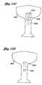
- This calibration procedureis described in U.S. Patent No. 4,621,643, assigned to Nellcor, Inc. Such a prior art sensor is depicted in FIGURE 1.
- the present inventioninvolves an improved method and apparatus to calibrate LEDs by utilizing this wavelength shift.
- the present inventioninvolves utilizing the wavelength shift to allow a single LED to provide more than one operating wavelength.
- the addition of a wavelengthprovides the ability to monitor additional parameters in a medium under test without adding an LED. In oximetry, this allows monitoring of additional constituents in the blood without adding additional LEDs to the oximeter sensor.
- the present inventionalso involves an application of the wavelength shift in LEDs to obtain physiological data regarding the oxygen saturation of blood without knowing the precise operational wavelength of an LED in the sensor.
- the networkhas a current source configured to provide a preselected source current with a light emitting diode coupled to the current source.
- the light emitting diodeis of the type that exhibits a shift in wavelength with a shift in a selected tuning parameter.
- the tuning parameteris drive current or drive voltage.
- a tuning resistor connected in parallel with the light emitting diodehas a value selected to draw at least a first portion of the preselected source current such that a second portion of the preselected source current passes through the light emitting diode. The second portion of the preselected source current is selected to cause the light emitting diode to generate light energy of a preselected wavelength.
- the tuned light transmission networkalso comprises a detector responsive to light energy from the light emitting diode to generate an output signal indicative of the intensity of the light energy.
- Another aspect of the present inventioninvolves a method for precalibrating a light generating sensor.
- the methodinvolves a number of steps.
- a first level of current passing through a light source as required to operate the light source at a preselected wavelengthis determined.
- a second level of currentis then defined.
- the second level of currentis higher than the first level of current.
- the second level of currentforms a drive current.
- a resistoris then selected which when coupled in parallel with the light source forms a tuned light source network. The resistor is selected such that when it is connected in parallel with the light source, it draws a sufficient amount of the drive current such that the first level of current passes through the light source.
- a light emitting diodeis selected of the type that exhibits a wavelength shift with a change in drive current through the light emitting diode for a range of drive currents.
- a source of electrical energyis coupled to the light emitting diode to provide the drive currents.
- the light emitting diodeis driven with a first level of drive current within the range of drive current to cause the light emitting diode to become active and operate at a first wavelength in response to the first level of drive currents.
- the light emitting diodeis then driven with a second level of drive current within the range of drive current and different from the first level of drive current to cause the light emitting diode to become active and operate at a second wavelength in response to the second level of drive current.
- the methodcomprises further steps. While the light emitting diode is operating at the first wavelength, light is transmitted as a first light energy at the first wavelength through the medium under test. The first wavelength is chosen for a first predetermined attenuation characteristic of the light energy as it propagates through the medium under test. The attenuated light energy is measured from the light emitting diode with a photodetector. In addition, while the light emitting diode is operating at the second wavelength, light energy is transmitted at the second wavelength through the medium under test. The second wavelength is chosen for a second predetermined attenuation characteristic of the light energy as it propagates through the medium under test. The attenuated light energy is measured at the second wavelength from the light emitting diode.
- the methodis used to determine the oxygen saturation of blood, and the medium under test comprises a portion of the human body having flowing blood.
- the methodfurther involves coupling the source of energy to a second light emitting diode which operates at a third wavelength distinct from the first and the second wavelengths. Further, the change in wavelength between the first and second wavelengths has a preselected value. Third light energy is transmitted at the third wavelength through the medium under test, and the third light energy is measured after propagation through the medium under test. Based upon the measurements, the oxygen saturation of the blood is determined.
- parameters in addition to oxygen saturationmay also be determined relating to the medium under test when the first wavelength has a known value, and the change in wavelength between the first and the second wavelengths has a preselected value.
- value of the second wavelengthis determined, and another parameter is calculated relating to the blood.
- the another parameteris the saturation of carboxyhemoglobin.
- another parameteris scattering.
- Methhemoglobinis another parameter that is Methhemoglobin.
- the first light emitting diodeis adjusted with an adjusting resistor such that the change in wavelength for an incremental change in current matches a preselected wavelength change.
- adjustinginvolves placing the adjusting resistor in parallel with the first light emitting diode, and selecting the value of the adjusting resistor to cause the first light emitting diode to exhibit the preselected change for the incremental change in current.
- an oximeter sensorhaving a first light emitting device configured to generate a light at a first known wavelength with a resistor in parallel with the first light emitting device.
- the light emitting devicecomprises a light emitting diode.
- the resistorcomprises an encoding resistor having a value indicative of the first known wavelength value. The value of the encoding resistor is sufficiently high such that the encoding resistor draws effectively insignificant current during active operation of the first light emitting device.
- the resistorcomprises a security resistor having a value indicative that the oximeter sensor is of a predetermined type.
- the value of the security resistoris sufficiently high such that the security resistor draws effectively insignificant current during active operation of the first light emitting device.
- Still a further aspect of the present inventioninvolves a method of tuning a light emitting diode to operate at a preselected wavelength within a range of wavelengths.
- the methodinvolves selecting a light emitting diode that exhibits a wavelength shift in response to a change in drive current within a range of drive current and driving the light emitting diode with a first drive current.
- the wavelength of the light emitting diode during operation at the first drive currentis measured, and, if the light emitting diode is not operating at the preselected wavelength, the drive current is adjusted within the range of drive current to a second drive current such that the light emitting diode operates at the preselected wavelength.
- the present inventioninvolves a sensor configured to transmit and detect light.
- the sensorhas at least one light emitting element, the light emitting element having an emission with a centroid transmission wavelength.
- the sensorfurther has first and second photodetectors, the emission of the light emitting element being within the response of the first and second photodetectors.
- a light directing memberis configured to direct light from the at least one light emitting element to the first and second photodetectors.
- a filter positioned between the second photodetector and the at least one light emitting elementhas a transition band selected to encompass the centroid transmission wavelength.
- the senorcomprises an oximeter sensor
- the at least one light emitting elementcomprises first and second light emitting diodes.
- the first light emitting diodehas a centroid wavelength in the red range and the second light emitting diode has a centroid wavelength in the infrared range.
- the filterhas a transition band which encompasses the centroid wavelength of the first light emitting diode.
- the light directing membercomprises an integrating optical sphere having the first and second photodetectors positioned about the sphere so as to receive substantially equivalent portions of light from the at least one light emitting element.
- light directing membercomprises a beam splitting member positioned to substantially equally divide light from the at least one light emitting member and to direct substantially equal portions of the light to the first and the second photodetectors.
- Still another aspect of the present inventioninvolves a method of determining the centroid wavelength of a light emitting element.
- the methodinvolves providing a set of a plurality of predetermined ratios, each of the plurality of predetermined ratios corresponding to an associated centroid wavelength.
- Lightis transmitted from the light emitting element to a first light detecting element to obtain a first intensity, and light is transmitted from the light emitting element through a filter which attenuates the light to a second light detecting element to obtain a second intensity.
- a ratio of the second intensity to the first intensityis then calculated.
- the ratiois compared to the set of predetermined ratios to reference the centroid wavelength of the light emitting element.
- the first and second light detecting elementscomprise the same light detecting element.
- the present inventionhas applicability to the use of medical probes and LEDs in general. However, an understanding is facilitated with the following description of the application of the principles of the present invention to oximetry.
- oximetrylight of a known wavelength is transmitted through a medium (e.g., a human digit such as a finger) under test.
- the light energyis partially absorbed and scattered by the constituents that make up the medium as the light propagates through the medium.
- the absorption and scattering of the light energy by any given constituentdepends upon the wavelength of the light passing through the constituent, as well as several other parameters.
- the absorption by a constituentis characterized with what is known as the extinction coefficient.
- FIGURE 2represents an exemplary graph 100 of the relationship between the extinction coefficient of three possible constituents of blood with respect to the wavelength of light.
- a first curve 102illustrates the relationship between the extinction coefficient of oxyhemoglobin (oxygenated hemoglobin) with respect to the transmission wavelength
- a second curve 104illustrates the relationship between the extinction coefficient of reduced hemoglobin with respect to the transmission wavelength
- a third curve 106illustrates the relationship between the extinction coefficient of carboxyhemoglobin (hemoglobin containing carbon monoxide) with respect to the transmission wavelength.
- This relationshipis well understood in the art.
- One wavelengthis required for each separate constituent in the medium.
- the wavelengths used for oximetryare chosen to maximize sensitivity of the measurement (i.e., oxygen saturation, etc.). These principles are well understood in the art.
- the amplitude of the energy incident on a homogeneous media having at least one constituent under testis approximately related to the amplitude of the energy transmitted through the media as follows: where I 0 is the energy incident on the medium, I is the attenuated signal, d i is the thickness of the i th constituent through which light energy passes, ⁇ i is the extinction (or absorption) coefficient of the i th constituent through which the light energy passes (the optical path length of the i th constituent), and c i is the concentration of the i th constituent in thickness d i . As well-understood in the art, this basic relationship is utilized to obtain oxygen saturation using conventional oximetry techniques.
- the simplified equation (1)will be utilized.
- the accuracy of the physiological measurementis impacted by the accuracy of the wavelength of the transmission LEDs because, as depicted in FIGURE 2, the extinction coefficient is dependent upon the wavelength of the transmission LEO.
- two LEDsone in the red wavelength range and one in the infrared wavelength range, are typically utilized in order to obtain the saturation measurement for a patient.
- the extinction coefficientis a critical variable in the equation. Accordingly, it is important that the oximeter be provided with information as to the specific wavelength of the transmission LEDs for the sensor.
- the wavelength of different LEDsalthough manufactured for a specified wavelength, varies for the same drive current from LED to LED due to manufacturing tolerances.
- One aspect of the present inventionprovides an apparatus and method for tuning each LED in a sensor such that the operating wavelengths for LEDs do not vary significantly from sensor to sensor.
- the tuningis performed by utilizing the wavelength shift exhibited in many LEOs in response to a change in drive current.
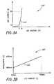
- FIGURES 3A and 3Billustrate this wavelength shift principle in two graphs.
- the graph 110 of FIGURE 3Adepicts (with a curve 112) current in the vertical axis versus voltage in the horizontal axis for a typical LED.
- the graph 110 of FIGURE 3Ais well-understood in the art.
- the wavelength of certain LEDsshifts in a substantially linear fashion in response to a corresponding change in drive current or voltage.
- the amount of wavelength shift per incremental change in drive currenttypically differs for each LED (designed for the same wavelength), just as the operating wavelength for LEDs (designed for a specific wavelength) varies for the same drive current from LED to LED.
- FIGURE 3Bdepicts an exemplary graph 120 of the wavelength of an LED in response to the drive current in the area of the shoulder depicted in FIGURE 3A.
- This graphdepicts in a curve 122 an exemplary wavelength shift for an LED in the red range in response to drive current changes.
- the slope of the curve 122 depicted in FIGURE 3Bvaries from LED to LED, as does the wavelength range.
- an incremental shift in drive current through the LEDscauses some incremental shift in the wavelength. Because this relationship is substantially linear in the area just beyond the shoulder of the curve 112 depicted in FIGURE 3A, in one preferred embodiment, the shift is obtained in the area beyond the shoulder.
- the graph of FIGURE 3Bis not meant to represent all LEDs, but merely to represent one possible wavelength shift corresponding to a particular change in drive current.
- one way to obtain a selected wavelengthis to drive the LEDs with the current necessary to obtain the wavelength.
- such embodimentwould require an oximeter design which varies the LED drive current for each sensor.
- a resistoris placed in parallel with an LED in order to adjust the drive current through the LED to a level which will result in a selected wavelength.
- the oximeter systemis designed to operate at the selected wavelength for each LED in the sensor.
- the oximeterneed only provide a fixed drive current. Accordingly, in one embodiment, the design of the oximeter is simpler in that it need not take into account variations of wavelength from sensor to sensor. The oximeter can simply be designed to operate at the selected wavelengths and have a fixed drive current.
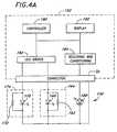
- FIGURE 4depicts one embodiment of a tuned sensor 150, connected to an exemplary oximeter system 152, according to the LED tuning aspect of the present invention.
- the sensor 150is illustrated with a first light source 160 and a second light source 170, typically LEDs.
- a first tuning resistor 162 connected in parallel with the first LED 160forms a first tuned LED network 164.
- a second tuning resistor 172is connected in parallel with the second LED 170 to form a second tuned LED network 174.
- the sensor 150further comprises a photodetector 180.
- a power source in the oximeter system, such as an LED driver 182is coupled to the tuned LED networks 164, 174 in order to provide a predetermined drive current at the input of the tuned LED networks 164, 174.
- the LED driver 182provides current to only one of the tuned LED networks 164, 174 at any given time.
- the photodetector 180is coupled to receiving and conditioning circuitry 184 in the oximeter system 152. In operation, the photodetector receives the attenuated light energy and responds with an output signal representing the intensity of the alternative light energy.
- the oximeter system 152further comprises a controller 190 with supporting resources and a display 192.
- the oximeter systemreceives the signals obtained from the sensor 150 and analyzes the signals to determine information regarding the medium through which the light energy has been transmitted. It should be understood that the oximeter system is depicted in simplified form for discussion purposes. Oximeter systems are well known in the art. One possible oximeter system comprises the oximeter system disclosed in International Publication No. WO 96/12435 published on 2 May 1996. Other oximeter systems are well known and can be designed to operate at the selected wavelengths.
- a typical mediummay include a finger 200 or an earlobe, as well-known in the art.
- Mediasuch as the finger and earlobe typically comprise a number of constituents such as skin, tissue, muscle, arterial blood and venous blood (having several constituents each), and fat. Each constituent absorbs and scatters light energy of a particular wavelength differently due to different extinction coefficients.
- the first LED 162emits incident light in response to the drive current from the LED driver 182. The light propagates through the medium under test. As the transmitted light propagates through the medium, it is partially absorbed by the medium. The attenuated light emerging from the medium is received by the photodetector 180.
- the photodetector 180produces an electrical signal indicative of the intensity of the attenuated light energy incident on the photodetector 180. This signal is provided to the oximeter system 152, which analyzes the signal to determine the characteristics of a selected constituent of the medium through which the light energy has passed.
- Tuning the first LED 160in accordance with the present invention involves determining the amount of current required to operate the first LED 160 at the selected wavelength and adjusting the current through the first LED 160 in order to obtain the selected wavelength.
- typical operational values for red LEDs used in oximetryrange between 645 nm and 670 nm.
- the oximetermay be designed to operate with a selected wavelength within that range, for example, 670 nm.
- the LEDs manufactured to produce the selected wavelength of 670 nminvolve manufacturing tolerances typically in the range of ⁇ 2-10 nm for the same drive current.
- the drive currentcan be varied in order to obtain the desired output wavelength for the LED. For instance, as illustrated in FIGURE 3B, the represented LED has an operating wavelength of 660 nm for the typical 50 mA drive current.
- the operating wavelengthbecomes the selected wavelength of the present example (670 nm).
- the present inventiontakes advantage of the observed wavelength shift in response to a drive current change to tune each LED to obtain the selected wavelength, such as 670 nm.
- the first LED 160is defined to exhibit the wavelength characteristic depicted in FIGURE 3B.
- the drive current from the LED driver 182is assumed to be preset or fixed.
- the drive currentis preferably somewhat larger than the drive current necessary to drive the first LED 160 alone (e.g., 100 mA or more). This is because the first tuning resistor 162 carries some of the fixed drive current from the LED driver 182.
- the first tuning resistor 162is selected to draw an appropriate amount of the fixed drive current to adjust the amount of current flowing through the first LED 160 to result in the selected output wavelength.
- the resistoris chosen to carry approximately 15 mA (of the 100 mA from the LED driver 182) in order to reduce the current through the first LED 160 to approximately 85 mA to obtain the 670 nm selected wavelength. Accordingly, each LED can be driven with the same fixed drive current from the LED driver 182, yet the current through any particular LED differs in accordance with the value of the associated tuning resistor. In this manner, the LED driver 182 can be designed to provide the same fixed drive current for every sensor connected to the oximeter. The oximeter system 152 is thus designed to make its calculation based on the assumption that the corresponding wavelengths remain constant from sensor to sensor.
- the resistor 210 depicted in FIGURE 5Acomprises a semiconductor substrate 212, a resistive coating pad 214, and connective conductors 216, 218.
- a tunable LED 220i.e., an LED that exhibits wavelength shift with drive current change
- the fixed (preset) drive currentis then applied with a current source 222 to the network formed by the substrate resistor 210 and the tunable LED 220.
- the operating wavelength of the tunable LEO 220is measured.
- the initial substrate resistorhas less resistance than will be necessary to obtain the desired output wavelength.
- a laseris used to scribe the resistive pad 214, as depicted by the line 224 in FIGURE 5B.
- the scribe line 224effectively removes a portion of the resistive pad 214, and thereby increases the resistance of the remaining resistive pad 214, as well known in the art.
- the increase in resistancecan be controlled very precisely.
- the resistive pad 214can be laser trimmed until the current through the tunable LED 220 causes the tunable LED 220 to generate the selected operating wavelength.
- the resulting resistor/LED pairforms a tuned LED network. This tuning method is advantageous because of the precision and the resulting low-cost of the tuned LED.
- each LED for each sensoris tuned in a similar manner such that the operating wavelength is a selected operating wavelength for the sensor.
- a two wavelength oximeter operatingmay have selected wavelengths for the two LEDs of 670 nm and 905 nm.
- a first LEDis tuned for the 670 nm selected wavelength
- a second LEDis tuned for the 905 nm selected wavelength.
- the tuning aspect of the present inventioninvolves using the principle of wavelength shift in an LED to tune each LED to obtain a respective selected operating wavelength.
- the manufacturing tolerancemay be too far from the respective selected wavelength to enable the use of the shift in wavelength to properly tune the LED: or the wavelength shift may be insufficient to obtain the selected wavelength. In one embodiment, such LEDs would not be utilized, and would be considered out of tolerance.
- the obtainable wavelength shiftis not sufficient to allow for proper tuning, it is also possible to use two LEDs having wavelengths very near each other and near the selected wavelength. One LED has a wavelength below the selected wavelength, and one LED has a wavelength above the selected wavelength. As the graph of FIGURE 6 illustrates, when two LEDs are both active and placed adjacent one another, the light from the two LEDs combines to form a combined wavelength which is the average wavelength of the two LEDs.
- the combined wavelengthhas a broader wavelength range, but has a known average.
- the wavelength shift of one or both of the two LEDscan be utilized using tuning resistors as described above such that the average wavelength is the selected wavelength. Accordingly, two LEDs (preferably tuned in accordance with the present invention as a pair) can be used to obtain the selected wavelength for operation in a given oximeter.
- the selected red wavelengthscould be 660 nm, 670 nm and 680 nm.
- the selected infrared wavelengthscould be 900 nm, 920 nm, and 940 nm, independent of the red wavelengths.
- Each sensorwould be tuned using the tuning resistors described above such that the red and infrared LEDs operate at one of the selected red and infrared wavelengths, respectively.
- An indicatorwould then be provided on the sensor, or the connector attached to the sensor, to allow the oximeter to determine which of the selected wavelengths is present on the sensor attached to the oximeter.
- a wavelength detection devicecould be provided with the oximeter system to determine which of the selected wavelengths is present in a sensor attached to the oximeter system.
- this embodimentrequires some means for the oximeter to determine which of the selected wavelengths is present on the attached sensor, the selected wavelengths are precise from sensor to sensor.
- Another aspect of the present inventioninvolves using the principle of wavelength shift in an LED for a given change in current in order to use a single LED to provide two operating wavelengths.
- Thisis advantageous in making physiological measurements, such as blood oximetry measurements, because for each additional wavelength added, the saturation of an additional constituent in the blood can be measured. For instance, with a two-wavelength oximeter, only the ratio of one of two constituents to the total of the two constituents (e.g., oxygen saturation) can be accurately monitored. If oxygen saturation is monitored with two wavelengths, other constituents which are significantly present in the blood affect the measurement of oxygen saturation.
- an additional constituent present in the bloodhas a significant effect upon the oxygen saturation reading for a particular patient, the failure to detect the constituent can be detrimental to the patient.
- An example of a constituent which, when present in the blood, will significantly impact the oxygen saturation reading provided by a two-wavelength oximeteris carbon monoxide. This is because the extinction coefficient magnitude for carboxyhemoglobin (depicted in the curve 106 of Figure 2) approaches the extinction coefficient of oxyhemoglobin (depicted in the curve 102 of FIGURE 2) for light energy in the range of 660 nm. Therefore, carboxyhemoglobin may be detected as oxyhemoglobin.
- the attending physicianmay fail to detect the lack of oxygen, and the increase of carbon monoxide in a patient. If an additional transmission wavelength is provided on the sensor, the oximeter can monitor another constituent, such as carboxyhemoglobin.
- the principle of wavelength shift in an LEDis utilized in order to drive one LED with two appropriate drive current levels to provide two distinct wavelengths.
- thisis accomplished by first driving an LED (which exhibits wavelength shift with drive current change) with a first known drive current to a first known wavelength, and then driving the same LED with a second known current to a second known wavelength.
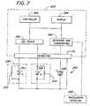
- FIGURE 7depicts one advantageous embodiment of a sensor 250 for blood oximetry measurements coupled to an oximeter system 252 designed in accordance with this aspect of the present invention.
- the sensor 250comprises a first LED 254 and a second LED 256.
- the first LED 254preferably operates in the red wavelength range and the second LED 256 preferably operates in the infrared wavelength range.
- the sensor 250further comprises a photodetector 258.
- the photodetector 258is coupled to receiving and conditioning circuitry 262.
- the oximeter systemis under the control of a controller 264 and has a display 266.
- an LED driver 260sequentially drives the LEDs 254, 256 with a predetermined drive current.
- the photodetector 258detects the light energy, attenuated by the medium under test.
- the oximeter 252receives and analyzes the signal from the photodetector 258 to determine information regarding the medium through which the light energy has been transmitted.
- the oximeter system 252is depicted in simplified form. Appropriate oximeter systems include the system disclosed in International Publication No. WO 96/12435, published on May 2, 1996. Other monitors well understood in the art also exist.
- the oximeter system 252is modified in accordance with the present invention to drive the shifting LED as described below.
- the first LED 254is the shifting LED and is used to provide two wavelengths.
- the wavelength shift principleis utilized.
- LEDsare evaluated at the time a sensor is manufactured, and an indicator is provided on the sensor which can be read by the oximeter system 252 to indicate the drive current change necessary in order to effectuate a desired shift in wavelength.
- Indicatorsmay comprise a resistor on the sensor or sensor connector, a memory on the sensor or sensor connector, or a similar device.
- the indicatorcan provide a indication to the oximeter of the amount of wavelength shift which is obtained due to a preset drive current change.
- wavelength detector 268for the oximeter, which allows the oximeter system 252 to detect the transmission wavelength of an active LED.
- Wavelength detectorssuch as a monochrometer, are well known in the art. However, conventional monochrometers are expensive and bulky. This description sets forth a more practical approach to detecting wavelength below.
- the LED driver 260changes the drive current until the desired wavelength is obtained, utilizing the wavelength detector 268 to monitor the wavelength.
- a network 270 of a slope adjusting resistor 272 and the first LED 254is slope adjusted such that a preselected change in drive current ( ⁇ I) entering the first slope adjusted network, causes a preselected shift in wavelength ( ⁇ ) in the first LED 254.
- ⁇ Idrive current
- ⁇wavelength
- each LEDexhibits an inherent slope of the curve 122.
- the slope of this curveoften differs from LED to LED, even for LEDs rated for a particular wavelength.
- the preselected wavelength shift ( ⁇ ) for each first LED in different sensorscorrespond to the same preselected drive current change ( ⁇ I). Accordingly, it is desirous that the first LED (for the present example) on different probes respond with the same preselected change in wavelength for the same change in drive current provided by the LED driver 260. In other words, it is advantageous that the slope of the curve 100 depicted in FIGURE 3B be the same for each corresponding LED network, since it is not typically the same for each individual LED. In this manner, the oximeter is designed to drive the LEDs with two drive current levels, where the two drive current levels are preselected and remain constant from sensor to sensor.
- a slope adjusting resistorsuch as the slope adjusting resistor 272
- the slope adjusting resistor 272can be used to alter the slope of the curve 122 exhibited for the particular corresponding LED network (e.g., the first slope adjusted LED network 270).
- the slope adjusting resistor 272if used to alter the slope, cannot also be used to tune the precise wavelength of the first LED 254.
- an indicatorsuch as a resistor or low cost memory device
- an indicatorcan be provided with the sensor 250 which can be read by the oximeter 252, which indicator provides the initial operating wavelength of the slope adjusted LED network 270.
- the substrate resistorfunctions as the slope adjusting resistor rather than a wavelength tuning resistor (i.e., the substrate resistor is adjusted to cause a preselected change in wavelength for a preselected change in drive current for the LED/resistor network).
- the substrate resistor 210 depicted in FIGURE 5A and 5Bis coupled to the first LED 254 to form the slope adjusting resistor 272.
- a laseris used to trim the resistor until the preselected change in drive current for the network 270 results in the preselected change in wavelength for the first LED 254.
- the second LED 256operates at a fixed infrared wavelength (e.g., 905 nm).
- a tuning resistor 274in the same manner as the tuning resistor 162 of FIGURE 4, to operate at the selected infrared wavelength.
- a tuned second (infrared) LED 256 and a slope adjusted first LED 254can be taken using the sensor 250.
- the senor 250 of FIGURE 7is first driven with an initial drive current to cause the first LED 254 to generate light energy of a first wavelength (e.g., 660 nm).
- the attenuated signal at this first wavelengthis detected by the photodetector 258 and received by the oximeter 252.
- the first slope adjusted LED 254is driven with a new drive current varied by the preselected change in drive current to cause the preselected wavelength shift to obtain a second wavelength (e.g., 675).
- the second wavelengthwill also be a known quantity.
- a third measurementis taken by driving the second LED 256 and receiving the attenuated signal with the photodetector 258. Measurements are stored in the oximeter system 252. Based upon the three measurements taken, the arterial saturation of two constituents of blood may be determined (e.g., oxyhemoglobin and carboxyhemoglobin), thus providing more precise information regarding the physiological makeup of the blood of a patient under test.
- two constituents of bloode.g., oxyhemoglobin and carboxyhemoglobin
- the first wavelengthmay be 660 nm
- the second wavelengthmay be 675 nm or 680 nm
- the third wavelengthwill be an infrared wavelength such as 900 nm or 905 nm.
- a further aspect of the present inventioninvolves an apparatus and method of measuring the saturation of a selected constituent in a medium under test (e.g., oxyhemoglobin in blood) without knowing the precise operational wavelength of one LED.
- a medium under teste.g., oxyhemoglobin in blood
- the operational wavelength for the LEDneed not be known if other information is also available, as further explained below.
- obtaining a known wavelength shift for a selected change in currentcan be accomplished by adjusting presently existing LEDs, such that the LEDs react to a preselected change in drive current ( ⁇ I) with a preselected change in wavelength ( ⁇ ).
- ⁇ Idrive current
- ⁇wavelength
- those LEDscan be used without adjustment.
- FIGURE 2depicts a graph illustrating the relationship between the typical extinction coefficient for three constituents of blood with respect to the transmission wavelength of light transmitted through the blood.
- the first curve 102 and second curve 104are of interest.
- the extinction coefficient of oxyhemoglobin for light transmitted between approximately 665 nm (indicated as ⁇ 1 on the graph) and 690 nm (indicated as ⁇ 2 on the graph)is substantially constant (more apparent when the Y-axis of FIGURE 2 is not a log scale axis).
- the extinction coefficient of the reduced hemoglobinexhibits a substantially linear relationship as a function of transmission wavelength.
- the attenuated signalis represented by Equation (1) above.
- the attenuated signal Iis received by the photodetector 258 and is a function of the ambient transmission, as set forth in Equation (1).
- Equation (1)can be expanded for these two constituents of blood:
- Equation (2)can be further expressed as follows: where:
- Equation (3)For determining oxygen saturation, where the light is transmitted at a first red wavelength ⁇ 1 , Equation (3) is expressed as follows:
- Equation (3)is expressed as follows:
- the oxygen saturationcan be computed without knowing the precise wavelength of one of the LEDs.
- the LED in the red rangeis chosen for illustration of this aspect of the present invention.
- the red LEDcan be adjusted to exhibit a preselected wavelength shift, even though the precise wavelength may not be known. Accordingly, the red LED can be driven with two different drive currents to obtain two different wavelengths, the shift between which is preselected and known.
- the precise wavelengthmay be unknown without some indication of at least the starting wavelength. In accordance with the present invention, as long as the preselected wavelength shift is known, the starting wavelength need not be known.
- the extinction coefficientsvary with respect to shifts in wavelength on the order of 1 ⁇ 3 nm
- the oximeter systemcan make measurements at three wavelengths ⁇ 1 , ⁇ 2 and ⁇ IR .
- Equations (3) and (4)a third equation in addition to Equations (3) and (4) is obtained.
- Equation (3)is expressed as follows:
- ⁇ 1 ⁇ 2( ⁇ 1 ⁇ 1 - ⁇ 1 ) ⁇ 1 is known for a known wavelength shift within the described range, because the change in the extinction coefficient ⁇ 1 is substantially linear.
- Equation (4)⁇ 1 ⁇ 1 C 1 + ⁇ 2 ⁇ 2 C 2
- S IR- d ( ⁇ 1 ⁇ IR C 1 + ⁇ 2 ⁇ IR C 2 )
- S 2- d (( ⁇ 1 ⁇ 1 - ⁇ 1 ) C 1 + ⁇ 2 ⁇ 2 C 2 )
- S 1 , S 2 , and S IRare calculated by measuring I and I BL . Accordingly, S 1 , S 2 , and S IR , are known values.
- the extinction coefficients ⁇ 1 and ⁇ 2 for the infrared wavelength LEDare assumed to be known because in the infrared wavelength of interest (e.g., 850 mn ⁇ 920 nm) and more particularly 890 nm ⁇ 910 nm), the extinction coefficient is substantially constant for both curves 102 and 104. In another embodiment, the accuracy would be improved slightly by tuning the LED.
- the extinction coefficients for oxyhemoglobin at ⁇ 1 and ⁇ 2are also known, as long as the wavelength is in the range where the extinction coefficient remains constant.
- this rangeis defined as 665 nm to 690 nm.
- ⁇ 1is also a known quantity because ⁇ 1 is linear with ⁇ .
- the total thickness of the medium, dgenerally is unknown for most applications. However, for the determination of oxygen saturation, as illustrated above, the thickness (d) cancels because saturation is a ratio.
- Equations (17), (18), and (19)provide three equations with three unknowns ( ⁇ 1 ⁇ 1 , C 1 and C 2 ). Algebraic techniques following those of Equations (6) to (13) may be applied to solve the three equations to obtain the oxygen saturation ratio of c 2 /(c 1 +c 2 ). Accordingly, it is not necessary to know the precise operating wavelength of the first LED 254, as long as the operating wavelength for the first LED 254 is in a known range where a preselected change in drive current causes a preselected change in the wavelength, and where the extinction coefficient of one constituent is constant and the extinction coefficient of the second constituent is substantially linear such that the change in the extinction coefficient for a preselected change in wavelength is also known.
- this aspect of the present inventionpermits the user to obtain physiological data without knowing the precise operational frequency of an LED.
- An additional aspect of the present inventioninvolves an improved calibration technique for an oximeter sensor where a resistor is utilized to code the LED rather than tune the LED.
- a resistoris utilized to code the LED rather than tune the LED.
- an encoding resistor 300utilizes a separate electrical connection lead and connects to a common ground lead 304.
- the characteristics of an LED as depicted in FIGURE 3Acan be utilized to provide a more cost effective coded or calibrated oximeter probe where the coding or calibration is provided using a coding resistor.
- FIGURE 8depicts a schematic diagram of an exemplary oximeter sensor where a coding resistor 332 can be read using one of the LED electrical connections rather than a separate electrical connection.
- a sensor 310comprises a first LED 312, a second LED 314 and a photodetector 316.
- the first LED 312has a first corresponding electrical connection 318; the second LED 314 has a second corresponding electrical connection 320; and the photodetector 316 has a corresponding electrical connection 322.
- Each of the LEDs 312, 314 and the photodetector 316are connected at their outputs to a common ground electrical connection 330.
- the coding resistor 332is coupled in parallel with the first LED 312 or the second LED 314.
- the coding resistor 332is not provided to tune the first LED 312 or to slope adjust the first LED network, but is provided as an indicator which can be read by an attached oximeter system 340.
- the resistorcan be used to indicate the operating wavelength of the first and second LEDs 312, 314, or more advantageously, to indicate the type of probe.
- the value of the coding resistor 332can be selected to indicate that the probe is an adult probe, a pediatric probe, a neonatal probe, a disposable probe or a reusable probe.
- coding resistorscould be provided across each of the LEDs 312, 314 to allow additional information about the probe to be coded without added leads.
- any resistor or impedance devicecould be used without it being used in parallel with the LEDs to encode the change in wavelength or other information for the LEDs.
- the coding resistorcould be utilized for security purposes.
- the value of the coding resistor, and the placement across the LED 312could be used to ensure that the probe is configured properly for the oximeter.
- the coding resistorcould be utilized to indicate that the probe is from an authorized supplier such as a "Masimo” standard probe, "Patient Monitoring Company 1" probe, "Patient Monitoring Company 2" probe, etc.
- the resistorneed not be a passive element. Coding information could also be provided through an active circuit such as a transistor network, memory chip, or other identification device, for instance Dallas Semiconductor DS 1990 or DS 2401 or other automatic identification chip.
- the oximeter system 340drives the first LED 312/coding resistor 332 combination at a level that is low enough that the LED draws effectively insignificant current because of the exponential relationship between I and V, as illustrated in the graph of FIGURE 3A.
- the LEDbecomes active in the area of the shoulder, designated with the A axis indicator. Below the voltage level at A, the LED is effectively inactive and draws effectively insignificant current. In other words, the current through the first LED 312 is negligible. Significantly all of the current through the first electrical connection 318 flows through the coding resistor 332.
- the current which flows through the coding resistor for the voltage appliedis measured by the oximeter system by measuring the current through the first electrical connection 318.
- the oximeter system 340determines the value of the coding resistor 332 which is preselected to indicate the type of probe, the operating wavelength or other parameters about the probe.
- the first LED 312is effectively removed from the electrical circuit.
- 0.5Vis a particularly advantageous voltage. At 0.5V, current through the LED is generally less than 1 ⁇ A (an insignificant amount).
- the coding resistor 332is chosen to be of a sufficiently high value that when the current supply to the first electrical connection 318 rises to a level sufficient to drive the first LED 312, the coding resistor 332 is effectively removed from the electrical circuit because of its high resistance as compared to the resistance of the first LED 312 at active operating currents.
- a coding resistorcan be used in connection with an oximeter LED sensor without the addition of an electrical connector dedicated to the coding resistor. This reduces the cost of the sensor in accordance with the present invention.
- the oximetercan monitor the coding resistor continuously by providing a .5V coding resistor reading signal at a frequency different from the LED drive current. For instance, if the LED drive current is turned on and off at a frequency of 625 Hz, the .5V coding resistor reading voltage can be provided at a frequency much lower than 625 Hz, such that the 625 Hz signal can be easily filtered with a low pass filter with a cutoff significantly below 625 Hz, but with a pass band which allows the .5V signal to pass. This would allow the oximeter to continuously monitor the coding resistor 332 in case of a change in the sensor by the system operator.
- FIGURE 8Ais similar to FIGURE 8, except that the first LED 312 and the second LED 314 are connected in a back-to-back configuration such that the first electrical connection 318 is required and the voltage can be alternated from positive to negative to draw current through either the second LED 314 or the first LED 312. This eliminates the need for an electrical connection to the oximeter probe, thereby further reducing the cost of the probe.
- the second LED 314is a red LED with a knee of approximately 2.0V and that the second LED 312 is an infrared (IR) LED with a knee of approximately 1.5V
- a positive voltageis advantageously applied to the first electrical connection 318 at approximately 0.5V in order to measure the coding resistor 332. Because the knee for the red LED is 2.0V, very little (less than 1 ⁇ A) current will flow through the red LED and essentially no current will flow through the infrared LED 312 (because the infrared LED 312 is reverse biased).
- the current which passes through the network of the first LED 312, the second LED 314, and the coding resistor 332is approximately equal to the current through the coding resistor 332.
- the resistance of the coding resistor 332is then easily determined via Ohms Law by dividing the voltage applied to the network by the current which flows through the network. Care must be taken to insure that the element (active or passive) does not create electromagnetic noise which could lead to reduced system signal to noise ratio.
- each LED sensoris configured with a wavelength detection configuration.
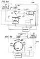
- FIGURE 9A and 9Bdepict diagrams of possible embodiments of LED sensors configured with filters. These sensor configurations can be used to obtain the wavelength of the LED for the sensor.
- a sensor 400comprises a transmission LED network 402, a first photodetector 404, a second photodetector 406, a diffuser 407, a beam splitter 408, an optical filter 410 and an optional optical filter 471.
- the transmission LED network 402, the first photodetector 404 and the second photodetector 406all couple to an oximeter system 412.
- a third photodetector 413is also depicted in dotted line to illustrate the photodetector for the oximetry measurement. This third photodetector 413 is not discussed in the following discussion which relates to the calibration portion of the oximeter probe 400.
- the transmission LED network 402preferably comprises at least two LEDs, one in the red wavelength range (e.g., 660 nm) and one in the infrared wavelength range (e.g., 905 nm). Determining the wavelength of one of the LEDs in the LED network 402 using the configuration of the sensor 400 depicted in FIGURE 9A is described below.
- the LED network 402transmits light 414 which first passes through the diffuser 407.
- the diffuser 407is provided advantageously in the preferred embodiment in order to remove polarization of the light because the beam splitter 408 is sensitive to polarized light, and most LEDs transmit some percentage of polarized light.
- the lightthen passes to the beam splitter 408 where it is divided.
- the beam splitter 408is preferably coated with a material which is partially reflective to light of the wavelength of the LEDs of interest in the LED network 402.
- the beam splitter 408reflects approximately one-half of the light 414 and directs it to the first photodetector 404.
- the remainder of the lightpasses through the beam splitter 408 and through the filter 410 and is received by the second photodetector 406.
- the oximeter system 412receives the intensity reading from the first and second photodetectors 404, 406 and utilizes the relative intensities from the first and second photodetectors 404, 406 to determine the centroid of the emission wavelength for the LEDs 402, as further explained below.
- the systemcan be calibrated by activating the infrared LED. This is possible because the first filter 410 is transparent to the infrared wavelength, and thus, each photodetector 404, 406 senses the same signal. In such an embodiment, the intensity outputs from the first and second photodetectors 404, 406 can be compared and equalized through calibration constants during run-time. This compensates for imprecision in the photodetectors beam splitter 408 and diffuser 407.
- the photodetectors 404, 406, the beam splitter 408 and the diffuser 407can be calibrated prior to delivery with a passive or active coding element 415 for each device.
- the box 415represents one or more coding elements.
- a single coding elementcould be used for all of the optical devices within the box 515.
- the elements provided for calibration(those within the box in dotted lines labelled 515) in this embodiment are positioned in a reusable portion of the probe such that the increased expense is not too significant.
- the filter 410may also have imprecision due to temperature sensitivity and imprecision of manufacturing process. Therefore, in order to calibrate for imprecision with respect to the filter 410 (preferably a shot glass) due to shift in temperature, a temperature detector 405 is provided in a preferred embodiment. Because temperature sensitivity in shot glass filters are well known, by detecting the temperature, the shift in filter characteristics can also be determined. With respect to the imprecision in manufacturing, a passive or active coding element 415 can be provided on the probe to provide information about the variation from a selected (ideal) filter characteristic (transition band for filter).
- FIGURE 9Bdepicts a sensor having a transmission LED network 420, a diffuser 421, a first photodetector 422, and a second photodetector 424.
- a third photodetector 431is depicted representing the photodetector used for oximetry measurements.
- the first and second photodetectors 422, 424are positioned at the interior periphery of an integrating optical sphere 426, or the like.
- the integrating optical sphere 426has an aperture 428 through which light 429 from the LED network 420 is directed for monitoring and for wavelength determination.
- the light which enters the apertureis reflected about the interior of the optical sphere 426, without significant absorption.
- the interior of the integrating optical sphereis reflective to the wavelengths of the light from the LED network 420.
- the interior of the integrating optical sphere 426scatters the light.
- the first and second photodetectors 422, 424are spaced laterally across the integrating optical sphere, with the aperture 428 positioned equidistance between the first and second photodetectors 422,424. In this manner, each of the first and second photodetectors422, 424 receive substantially the same amount of light originating from the LED network 420.
- the second photodetector 424has an associated low pass optical filter 430, through which the light incident on the second photodetector 424 passes prior to reaching the second photodetector 424. Accordingly, like the embodiment of FIGURE 9A, the second photodetector 424 in FIGURE 9B receives light attenuated by the filter 430, and the first photodetector 422 receives light unattenuated by the filter 430.
- the system of Figure 98can be calibrated by activating the infrared LED if no infrared filter (corresponding to the filter 411 in Figure 9A) is used. This is possible because the filter 430 is transparent to the infrared wavelength, and thus, each photodetector 422, 424 senses unfiltered signal (which ideally would be the same). In such an embodiment, the intensity outputs from the first and second photodetectors 422, 424 can be compared and equalized through calibration constants during run-time. This compensates for imprecision in the photodetectors, optical sphere, and diffuser.
- the photodetectors 422, 424, the optical sphere 426, and the diffuser 421can be calibrated prior to delivery with passive or active coding element(s) 432 for each device.
- the filter 430may have imprecision due to temperature sensitivity and imprecision due to manufacturing. Therefore, in order to calibrate for imprecision with respect to the filter 430 (preferably a shot glass) due to shift in temperature and manufacturing tolerances, a temperature detector 425 is provided in a preferred embodiment, as with the embodiment of Figure 9A. With respect to the imprecision in manufacturing, a passive or active coding element 432 can be provided on the probe to provide information about the variation from a selected (ideal) filter characteristic (transition band for filter).
- a single memory element or other passive or active element (415, 432)could be provided with enough identification capability to provide characteristic information for each of the diffuser, the photodetectors, filters, and the beam splitter (or optical sphere).
- a memory device or transistor networkcould be provided with several bits of information for device.
- the wavelength of the red LEDis the most critical for blood oximetry. Accordingly, accurate determination of the centroid operating wavelength of the red LED in the LED networks 402, 420 is desired.
- the filters 410, 430advantageously are selected to partially attenuate light in the red wavelength range, and pass light in the infrared range unattenuated.
- LEDs for use in blood oximetry and the likehave an emission characteristic similar to the emission curve depicted with the curve 440 of FIGURE 10A.
- the ideal LEDhas a centroid wavelength at ⁇ 0 (e.g., 660 nm).
- the actual centroid wavelength for a batch of LEDs with a target centroid wavelength of ⁇ 0differs due to manufacturing tolerances.
- the emission curvemay be shifted to the right as in the dotted emission curve 440A depicted in FIGURE 10A.
- the actual centroid wavelengthis significant in accurate oximetry measurements.
- the filters 410, 430preferably have a response as depicted by the curve 450 in FIGURE 10B.
- the filter transition bandadvantageously extends from a lower anticipated wavelength ⁇ 1 to an upper anticipated wavelength ⁇ 2 .
- the range ( ⁇ 1 ⁇ ⁇ 2 )preferably encompasses the anticipated variance in wavelengths for LEDs due to manufacturing tolerances. In other words, the manufacturing tolerance range for LEDs manufactured to have a target wavelength of ⁇ 0 , should not extend beyond the upper or lower bounds of the filter transition band.
- a ratio of the overall intensity detected from a sensor LED without filtering to the intensity of the same sensor LED detected with filteringprovides useful information, as further explained.
- FIGURE 10Cis illustrative of the ratio for an LED having a wavelength just above than the target wavelength ⁇ 0 .
- the LED emission without filteringis represented by the LED emission curve 440A.
- the emission with filteringis depicted by the filtered emission curve 441.
- the filtered emission curve 441represents the filter response multiplied by the LED emission without filtering as well understood for filtered emission.
- the significant ratiois the ratio of the area under the filtered LED emission curve 441 (illustrated with cross hatching) to the area of under the unfiltered LED emission curve 440A. It will be understood that this ratio will vary from 0 - 1, for LEDs with a centroid in the range ⁇ 1 - ⁇ 2 , and assuming the same filter response.
- This ratio of the two areascan be determined from the ratio of intensities received from the photodetectors 404, 406 or 422, 424 as follows: Let the normalized intensity of the unfiltered light I 2 ( ⁇ ) and the intensity of the filtered light, I 1 ( ⁇ ) be represented by the following equations.
- the energy of the unfiltered light as received by the photodetector 404, 422can be expressed as the integral over the range of wavelengths of the LED emission as follows: where I L ( ⁇ ) is the LED emission vs. wavelength ( ⁇ ) and P( ⁇ ) is the photodiode response vs. wavelength ( ⁇ ).
- the signal of the first photodetector 404, 422(no filter) will be as follows:
- the energy of the light received by the second photodetector 406, 424 which has passed through the filter 410, 430can be expressed as follows:
- the generalized ratio of equation (34)is a ratio of the entire area of the LED emission attenuated by filtering (designated with cross-hatching in FIGURE 10C) to the area under the entire LED emission curve.
- the function E normis single valued and monotonic in the area ( ⁇ 1 - ⁇ 2 ) and depends only on the centroid wavelength shift of the LED with respect to the center of the transition band, ⁇ 0, of the filter.
- the ratio of the energy detected by second photodetector (filter present) to the energy detected by the first photodetector (filter not present) in the wavelength range ( ⁇ 1 - ⁇ 2 ),will be a value between 0 and 1.
- a ratiocan be calculated to correspond to each possible LED wavelength in the range ( ⁇ 1 - ⁇ 2 ).
- a test batch of LEDs representing the range of wavelengths ( ⁇ 1 - ⁇ 2 )can be used to obtain corresponding ratios of the intensity of filtered light to unfiltered light.
- An accurate wavelength detection devicesuch as a monochrometer, can be used to measure the centroid wavelength for each tested LED.
- the centroid wavelengthcan be stored for each tested LED in association with the measured ratio for each tested LED. This leads to a normalized photodiode response, which can be referenced to obtain the wavelength of an LED having an unknown wavelength in the wavelength range ( ⁇ 1 - ⁇ 2 ).
- the wavelength of the LED for the sensorcan be determined by taking the ratio of the intensities of the second and first photodetectors, and using the ratio to reference the normalized photodiode response to find the wavelength. In the present embodiment, this is accomplished with a look-up table stored in a memory for the oximeter system. The look-up table stores the ratio values corresponding to associated wavelength values.
- the oximetersimply continually initiates measurements for calibration purposes.
- the oximeteruses the method described above, calculates the ratio between the two intensities (filtered and unfiltered) and obtains the respective wavelength for the sensor. This is for testing purposes.
- the LEDs or shot glass purchasedadvantageously should produce a ration less than 1 and greater than 0, otherwise the LED wavelength will be undeterminable.
- the filters of the sensors of FIGURES 9A and 9Bare chosen with the center of their transition band, ⁇ 0 , in the red wavelength range. As seen from the filter response curve of FIGURE 10B, if the center of the transition band is in the red range, the infrared light will not be attenuated by the filter.
- FIGURE 11depicts the response curve for three filters, adequate for the present invention, depending upon the expected wavelengths.
- a first filterhas the center of its transition band at 645 nm
- a second filterhas the center of its transition band at 665 nm
- a third filterhas the center of its transition band at 695 nm.
- Other filtersare also appropriate depending upon the target centroid wavelength.
- the filter 411can be provided as a filter, with the center of its transition band selected at the anticipated or target infrared wavelength in erder to calibrate the infrared LED as well.
- the second filter 411would pass red wavelengths (would be transparent to the red LED light) and would have its transition band centered around 900 or 905nm. Such a filter is depicted in FIGURE 11A.
- the wavelength detection described abovecould also be implemented with a sensor having only one photodetector, and a removable filter. The operator would initiate an intensity measurement as prompted by the oximeter without the filter. Then, the operator would place the filter in the light path between the LED and the photodetector, and initiate a second reading. The ratio of the second reading to the first reading provides the ratio I norm , which is used to reference the operating wavelength.
- FIGURES 12 - 14illustrate three different of probes used in medical monitoring of patients.
- FIGURE 12depicts a wrap-around type probe 500 with an associated connector 502 coupled to a cable 504 which couples to an oximeter system (not shown in FIGURE 12).
- FIGURE 12Adepicts the bottom of the connector 502.
- FIGURE 12Bdepicts a bottom view of the wrap-around probe of FIGURE 12, and
- FIGURE 12Cdepicts a side view of the wrap-around probe of FIGURE 12.
- the wrap around probe 500has an LED emitter 506, a photodetector 508 at the end of a cavity 509, a flexible circuit 510, and friction electrical connection fingers 512.
- the probe 500also has a connection port 519.
- the wrap-around probewould also have a light tunnel 514 (FIGURE 12B) to channel some of the light from the emitter 506 to the connector 502.
- all of the probe calibration elements marked in the dashed line 515, 515A in Figures 9A and 9Bare positioned in a cavity 516 (FIGURE 12A) which receives the light channeled through the light tunnel 514 and coupled to the connector 502 via an aperture 518 at the end of the light tunnel 514.
- electrical friction connectors 520 on the connectorare configured to couple with the electrical connectors 512 of the wrap-around probe 500.
- the flexible circuitconnects the emitters 506 and the detector 508 to the connection fingers 512.
- the wrap-around probeis placed on the digit of a patient, and the photodetector 508 is positioned opposite the emitter 506 so as to receive light from the emitter 506 attenuated by transmission through a fleshy medium.
- FIGURE 13depicts another embodiment of a wrap-around probe 530 for medical monitoring of infants.
- the probehas a first flexible portion 532 configured to be wrapped about the digit of a neonate.
- a second flexible membercarrying emitters 534 (LEDs) and photodetector 536.
- LEDsemitters
- photodetector 536photodetector 536.
- a fiber optic 538is provided to carry part of the light from the emitter 534 to the connector port 540 of the probe 530. In this manner, the same connector 502 having a photodetector can be utilized with the infant style probe of FIGURE 13.
- a light channel or tunnelcould be used instead of the fiber optic to carry a portion of the light from the emitter 534 to the connector port 540.
- the same connector 542is used for the neonatal probe 530. Accordingly, as with the embodiment of FIGURE 12, all of the calibration elements within the dotted box 515, 515A of FIGURES 9A and 9B are positioned within the connector 502.
- FIGURE 14depicts yet another probe for use in medical monitoring.
- the probe of FIGURE 14comprises a clip-on probe 550 which couples via a cable 552 to a connector port 554 which is the same as the connector port 540 of FIGURE 13 and the connector port 519 of FIGURE 12.
- the clip-on probecarries emitters 556 and a photodetector 558. With this embodiment, some light from the emitters 556 enters a fiber optic 560 which channels light to the connector port 554 as in the embodiment of FIGURE 13.
- the probe calibrations elements within the same connector 502are preferably contained within the connector 502 which is advantageously the same as the connector for the embodiments of FIGURES 12 and 13.
- FIGURES 15-150depict yet another embodiment of a wrap-around probe 600 comprising a flexible wrap portion 602 with an associated connector 604 coupled to a cable 506 which couples to an oximeter system (not shown in FIGURE 15).
- FIGURE 15depicts a perspective view of the entire probe 600.
- FIGURE 15Adepicts the underside of the connector 604.
- FIGURE 15Cdepicts a top view of the wrap portion 602 and
- FIGURE 150depicts a bottom view of the wrap portion 602.
- the connector 604has two portions: an emitter portion 610 and a connection portion 612.
- the emitter portion 610advantageously contains the emitters (such as LEDs) for the selected wavelengths.
- This emitter portion 610can be reused for a period of time, preferably weeks to months, thereby allowing for further reduced cost of the wrap-around portion 602 which is disposable after each use. In other words, emitters need not be provided for each wrap portion 602. Yet, the emitter portion 610 is removably coupled to the connection portion 612 of the connector 604, allowing the connection portion 612 to be reusable for a much longer period of time.
- the wrap portion 602is flexible and disposable after each use with a very low cost.
- the wrap portionhas a flexible layer 626 made from polymer or other flexible materials and has a connector port 614 on the flexible layer 626.
- the connector port 614has electrical finger friction connectors 616 which are adapted to couple to electrical finger friction connectors 620 (FIGURE 15A) on the bottom of the connection portion 612 of the connector 604.
- the electrical finger friction connectors 616 for the wrap portion 602couple to a flexible circuit 618 which connects to a detector 622 which is shielded (not shown) for the detector 622. Two of the connections couple to the detector 622 and the third is for the shield which is preferably a conventional Faraday shield to protect the detector from electromagnetic interference and the like.
- the wrap around probe 600has an aperture 624 that provides a window for the transmission of light energy from the emitters in the emitter portion 610.
- the emittersare positioned to transmit light through an aperture 628 (FIGURE 15A) in the emitter portion 610 which is configured to match with the aperture 624 in the wrap portion 602 when the connector 604 is positioned in the connection port 614.
- the lighttransmits from the emitters in the emitter portion 610 through the aperture 628 in the emitter portion 610 and through the aperture 624 in the wrap portion 602 when the connector 604 is inserted into the connector port 614 and the emitters are activated.
- the wrap portion 602is wrapped around a digit of the patient (e.g., a finger) and the detector 622 is positioned to receive light transmitted through the aperture 624 and through at least a portion of the digit.
- the wrap portion 602can be wrapped around a finger in a manner that the detector 622 is opposite the aperture 624 from which light energy is transmitted.
- the probe 600is used for the calibratable probe of FIGURES 9A and 9B.
- the connection portion 612has the elements in the dotted boxes 515 and 515A of FIGURES 9A and 9B positioned in the connection portion 612.
- the calibration elementsare reusable, yet work with the LEDS in the emitter portion 610 to form a calibratable embodiment.
- the emittersare positioned in the emitter portion 610 such that the majority of the light energy transmits through the aperture 628 and that some light energy transmits to a light aperture 620 in the end of the connection portion 612 ( Figure 15B).
- the connection portion 612contains the calibration elements depicted in the boxes 515 and 515A (FIGURES 9A AND 9B) housed in the connection portion 612.
- Figure 15Bdepicts an end view of the connection portion 612 depicting the light channel 620 and two electrical connector 613A, 613B which provide connections for LEDs (red and infrared connected back-to-back in the present embodiment) in the emitter portion.
- LEDsred and infrared connected back-to-back in the present embodiment
- the apparatus and method of the present inventionmay be employed in any circumstance where a measurement of transmitted or reflected energy is required, including but not limited to measurements taken on a finger, an earlobe, or a lip.
- a measurement of transmitted or reflected energyincluding but not limited to measurements taken on a finger, an earlobe, or a lip.
- the apparatus and method of the present inventionmay be employed for any LED application that is wavelength sensitive.
- the present inventionmay thus be embodied in other specific forms without departing from its spirit or essential characteristics.
- the described embodimentsare to be considered in all respects only as illustrative and not restrictive.
- the scope of the inventionis, therefore, indicated by the following appended claims. All changes which come within the meaning and range of equivalency of these claims are to be embraced within their scope.
Landscapes
- Physics & Mathematics (AREA)
- Spectroscopy & Molecular Physics (AREA)
- Health & Medical Sciences (AREA)
- Life Sciences & Earth Sciences (AREA)
- General Physics & Mathematics (AREA)
- General Health & Medical Sciences (AREA)
- Pathology (AREA)
- Engineering & Computer Science (AREA)
- Immunology (AREA)
- Biochemistry (AREA)
- Analytical Chemistry (AREA)
- Chemical & Material Sciences (AREA)
- Biophysics (AREA)
- Surgery (AREA)
- Animal Behavior & Ethology (AREA)
- Molecular Biology (AREA)
- Public Health (AREA)
- Veterinary Medicine (AREA)
- Medical Informatics (AREA)
- Heart & Thoracic Surgery (AREA)
- Biomedical Technology (AREA)
- Optics & Photonics (AREA)
- Physiology (AREA)
- Cardiology (AREA)
- Mathematical Physics (AREA)
- Theoretical Computer Science (AREA)
- Toxicology (AREA)
- Pulmonology (AREA)
- Measurement Of The Respiration, Hearing Ability, Form, And Blood Characteristics Of Living Organisms (AREA)
- Investigating Or Analysing Materials By Optical Means (AREA)
- Electrotherapy Devices (AREA)
- Led Devices (AREA)
- Electrochromic Elements, Electrophoresis, Or Variable Reflection Or Absorption Elements (AREA)
- Holo Graphy (AREA)
- Spectrometry And Color Measurement (AREA)
- Control Of Indicators Other Than Cathode Ray Tubes (AREA)
- Non-Silver Salt Photosensitive Materials And Non-Silver Salt Photography (AREA)
- Lasers (AREA)
Abstract
Description


- d
- is the thickness of the medium.
- ε1λ
- is the absorption coefficient of reduced hemoglobin at wavelength λ,
- ε2λ
- is the absorption coefficient of oxyhemoglobin at wavelength λ,
- c1
- is the concentration of reduced hemoglobin,
- c2
- is the concentration of oxyhemoglobin,
- εi
- is the absorption coefficient of the jth layer of attenuating material (not including oxyhemoglobinand reduced hemoglobin),
- di
- is the thickness of the jth layer of attenuation material (not including oxyhemoglobin and reducedhemoglobin), and
- ci
- is the concentration of the jth layer of attenuating material (not including oxyhemoglobin andreduced hemoglobin).


- s
- is a value obtained by measuring I with the photodetector and calculating the ratio of I to IBL aftertaking the natural log.


Claims (55)
- A sensor used in an oximeter system for monitoring oxygen level in blood of apatient, the sensor comprising:at least one light emitting diode configured to transmit light energy throughhuman tissue carrying the blood, wherein the blood attenuates the light energy;a photodetector configured to detect the attenuated light energy; andan information element configured to indicate a characteristic of the patient,wherein the information element is electrically coupled in parallel with the at least onelight emitting diode.
- The sensor of Claim 1, wherein the information element indicates that the patientis a neonate.
- The sensor of Claim 1, wherein the information element indicates an age range ofthe patient.
- The sensor of Claim 1, wherein the sensor is detachable from the oximetersystem.
- The sensor of Claim 1, wherein the information element is a resistor.
- The sensor of Claim 1, wherein the information element is a transistor network.
- The sensor of Claim 1, wherein the information element is an automaticidentification chip.
- The sensor of Claim 1, wherein the information element is a memory chip.
- A medical probe for non-invasive monitoring of a constituent in blood, saidmedical probe comprising:a light emitter configured to transmit light of a selected wavelength, wherein saidlight is attenuated after traveling through a medium with blood flow;a detector configured to receive said attenuated light; andan information element electrically coupled to said light emitter and configured toindicate a patient type.
- The medical probe of Claim 9, wherein the information element is a passiveelement.
- The medical probe of Claim 9, wherein the information element is an activecircuit.
- The medical probe of Claim 9, wherein the patient type is a pediatric patient.
- The medical probe of Claim 9, wherein the patient type is an adult patient.
- A medical probe for non-invasive monitoring of a constituent in blood, saidmedical probe comprising:a light emitter configured to transmit light of a selected wavelength, wherein saidlight is attenuated after traveling through a medium with blood flow and the selectedwavelength of the light emitter changes to monitor a different constituent;a detector configured to receive said attenuated light; andan information element electrically coupled to said light emitter and configured toindicate a patient type.
- A probe for medical monitoring of a patient, the probe comprising:a light emitting diode configured to receive a drive signal and to generate lightenergy for transmission through a fleshy medium of the patient;a photodetector configured to receive the light energy attenuated by thetransmission through the fleshy medium and to generate an output signal correspondingto intensity of the attenuated light energy; andan indicator configured to communicate a characteristic of the patient, wherein theindicator is electrically coupled in parallel with the light emitting diode.
- The probe of Claim 15, wherein the indicator draws insignificant current duringactive operation of the light emitting diode.
- A probe for medical monitoring of a patient, the probe comprising:a light emitting diode configured to receive a drive signal and to generate lightenergy for transmission through a fleshy medium of the patient;a photodetector configured to receive the light energy attenuated by thetransmission through the fleshy medium and to generate an output signal correspondingto intensity of the attenuated light energy; andan indicator configured to communicate a characteristic of the patient, wherein theindicator is electrically coupled in parallel with the light emitting diode, and the drive signal operates at a relatively high frequency, and the indicator communicates at arelatively low frequency.
- A medical probe configured to transmit and detect light, said medical probeadapted to be positioned adjacent tissue material, said medical probe comprising:at least one light emitting element, said light emitting element having an emissionwith a centroid transmission wavelength, said medical probe configured with said lightemitting element such that when said medical probe is positioned adjacent said tissuematerial, at least a portion of said emission passes through said tissue material;wavelength detection instrumentation comprising:first and second photodetectors, said emission within the response of saidfirst and second photodetectors;a light directing member configured to direct light from said at least onelight emitting element to said first and second photodetectors, said light directingmember comprising an integrating optical sphere having said first and secondphotodetectors positioned about said sphere so as to receive substantiallyequivalent portions of light from said at least one light emitting element; anda filter positioned between said second photodetector and said at least onelight emitting element, said filter having a transition band selected to encompasssaid centroid transmission wavelength; andan interface adapted to couple the medical probe to a medical instrument.
- The medical probe of Claim 18, said medical probe comprising an oximeterprobe, said at least one light emitting element comprising first and second light emitting diodes,said first light emitting diode having a centroid wavelength in the red range and second lightemitting diode having a centroid wavelength in the infrared range, said filter having a transitionband which encompasses the centroid wavelength of said first light emitting diode.
- The medical probe of Claim 18, wherein one of said first and secondphotodetectors is mounted such that when said medical probe is positioned adjacent said tissuematerial, said one of said photodetectors is positioned to receive light from said at least one lightemitting element which has passed through said tissue material.
- The medical probe of Claim 18, further comprising a third photodetector, saidthird photodetector positioned such that when said medical probe is positioned adjacent saidtissue material, said third photodetector is positioned to receive light from said at least one lightemitting element which has passed through said tissue material.
- A method of determining the wavelength of a light emitting element positioned ona medical sensor probe, said method comprising the steps of:providing a set of a plurality of predetermined ratios, each of said plurality ofpredetermined ratios corresponding to an associated centroid wavelength;contemporaneously with or just prior to patient monitoring, transmitting lightfrom said light emitting element to a first light detecting element to obtain a firstintensity;transmitting light from said light emitting element through a filter whichattenuates the light to a second light detecting element to obtain a second intensity;calculating a ratio of said second intensity to said first intensity; andcomparing said ratio to said set of predetermined ratios to reference the centroidwavelength of said light emitting element.
- The method of Claim 22, wherein said first and second light detecting elementscomprise the same light detecting element, said steps of transmitting occurring sequentially.
- An oximeter sensor configured to transmit light and detect light, said oximetersensor adapted to be positioned adjacent tissue material, said oximeter sensor comprising:at least a first light emitting element, said light emitting element configured withsaid oximeter sensor such that when said oximeter sensor is positioned adjacent saidtissue material, a first portion of light from said light emitting element will passthroughout said tissue material;a light diffuse, said light diffuser adapted to remove polarization of light emittedfrom said light emitting element;a wavelength detection device comprising:at least two photodetectors; andat least one filter positioned such that light from said light emittingelement passes through said filter prior to detection by at least one of said at leasttwo photodetectors; andan interface coupled to said at least two photodetectors and to said light emittingelement and adapted to couple said oximeter sensor to an oximeter instrument.
- The oximeter sensor of Claim 24, wherein one of said first and secondphotodetectors is mounted such that when said oximeter sensor is positioned adjacent said tissuematerial, said one of said photodetectors is positioned to receive light from said at least a firstlight emitting element which has passed through said tissue material.
- The oximeter sensor of Claim 24, further comprising a third photodetector, saidthird photodetector positioned such that when said oximeter sensor is positioned adjacent saidtissue material, said third photodetector is positioned to receive at least a portion light from saidat least a first light emitting element which has passed through said tissue material.
- The oximeter sensor of Claim 26, further comprising a light directing member,said light directing member configured to direct substantially equal portions of at least a portionof the light from said at least a first light emitting element to said first and second photodetectors.
- The oximeter sensor of Claim 24, further comprising a second light emittingelement, said at least a first light emitting element having a centroid wavelength in the red range,and said second light emitting element having a centroid wavelength in the infrared range.
- A method of determining the wavelength of a light emitting element for a medicalprobe, said method comprising the steps of:providing a set of plurality of predetermined ratios, each of said plurality ofpredetermined ratios, corresponding to an associated centroid wavelength;in the clinical setting, transmitting light from said light emitting element to a firstlight detecting element to obtain a first intensity;transmitting light from said light emitting element through a filter whichattenuates the light to a second light detecting element to obtain a second intensity;calculating a ratio of said second intensity to said first intensity; andcomparing said ratio to said set of predetermined ratios to reference the centroidwavelength of said light emitting element.
- An oximeter sensor comprising:a first light emitting device configured to generate light at a first knownwavelength and which is active at or above a first voltage level and inactive below saidfirst voltage level;an information element electrically connected in parallel with said first lightemitting device; anda detector responsive to light which originated from said first light emitting deviceto generate an output signal.
- The oximeter sensor of Claim 30, wherein said information element operates at avoltage level below said first voltage level.
- The oximeter sensor of Claim 30, where said information element comprises aresistor.
- The oximeter sensor of Claim 30, wherein said information element comprises animpedance network.
- The oximeter sensor of Claim 30, wherein said information element comprises amemory device.
- The oximeter sensor of Claim 30, wherein the light emitting device comprises alight emitting diode.
- The oximeter sensor of Claim 30, wherein said information element comprises anencoding resistor, the resistance value of said encoding resistor indicative of the first knownwavelength value, and the resistance value sufficiently high such that the encoding resistor drawseffectively insignificant current during active operation of said first light emitting device.
- The oximeter sensor of Claim 30, wherein said information element comprises asecurity element, the security element indicative that the oximeter sensor is of a predeterminedtype.
- The oximeter sensor of Claim 37, wherein said security element comprises aresistor with a resistance value that is sufficiently high such that the resistor draws effectivelyinsignificant current during active operation of said first light emitting device.
- A sensor system comprising:at least one light emitting element;at least one photosensing element;an information element electrically coupled in parallel with said at least one lightemitting element;a controller connected to said at least one light emitting element and saidinformation element coupled in parallel, said controller addressing said informationelement below a first voltage and said at least one light emitting element at or above saidfirst voltage.
- The sensor system of Claim 39, wherein said at least one light emitting element isa light emitting diode and said information element is a resistor.
- The sensor system of Claim 40, wherein the resistance of said resistor issufficiently high that current flowing through said resistor is insignificant when said lightemitting diode is addressed at or above said first voltage.
- The sensor system of Claim 40, wherein said resistor has a resistance valueindicative of a first known wavelength value for said at least one light emitting element.
- An oximeter sensor system comprising:a first light emitting device configured to generate light at a first knownwavelength when active said first light emitting device active at and above a first voltageand inactive below said first voltage:an information element electrically connected in parallel with said first lightemitting device;a photodetector responsive to light which originated from said first light emittingdevice at a voltage at or above said first voltage to activate said first light emitting device;anda controller coupled to said light emitting device and said information element,said controller addressing said information element at a voltage below said first voltageand addressing said first light emitting device at a voltage at or above said first voltage toactivate said first light emitting device.
- The oximeter sensor system of Claim 43, wherein said information elementcomprises an encoding resistor, the resistance value of said encoding resistor indicative of thefirst known wavelength value.
- The oximeter sensor system of Claim 44, wherein the resistance value of saidresistor is sufficiently high such that most of the current flows through the first light emittingdevice when a voltage at or above the first voltage is applied across said first light emittingdevice and resistor.
- The oximeter sensor system of Claim 43, wherein said information elementcomprises a memory device.
- The oximeter sensor system of Claim 43, wherein at a voltage level below saidfirst voltage level, said light emitting device draws substantially insignificant current.
- The oximeter sensor system of Claim 43, further comprising a second lightemitting device configured to generate light at a second known wavelength, said second lightemitting device connected in a back-to-back configuration with said first light emitting device.
- The oximeter sensor system of Claim 43, wherein said controller is configured tocyclicly activate said first light emitting device at or above said first voltage and cyclicly readsaid information element at a voltage below said first voltage and cyclicly read said informationelement at a voltage below said first voltage.
- A sensor system comprising:at least one light emitting element;at least one photosensing element;an information element electrically coupled in parallel with said at least onephotosensing element;a controller connected to said at least one photosensing element and saidinformation element in parallel, said controller addressing said information element at apredetermined voltage wherein said at least one photosensing element is inactive at saidpredetermined voltage.
- A physiological sensor comprising:a first light emitting device configured to generate light and which is active at orabove a predetermined non-zero voltage, and inactive below said predetermined voltage;an information element electrically connected in parallel with said first lightemitting device, said information element readable at a voltage below said predeterminednon-zero voltage; anda detector responsive to light which originated from said first light emitting deviceto generate an output signal.
- The physiological sensor of Claim 51, wherein said first light emitting device is alight emitting diode which draws insignificant current at a non-zero voltage below saidpredetermined voltage.
- The physiological sensor of Claim 52, wherein said information element is aresistor.
- The physiological sensor of Claim 53, further comprising a second light emittingdevice electrically connected in parallel and opposite polarity with said first light emitting device.
- The physiological sensor of Claim 53, wherein said predetermined non-zerovoltage is approximately 1.5 volts.
Applications Claiming Priority (4)
| Application Number | Priority Date | Filing Date | Title |
|---|---|---|---|
| US08/478,493US5758644A (en) | 1995-06-07 | 1995-06-07 | Manual and automatic probe calibration |
| US478493 | 1995-06-07 | ||
| EP01113641AEP1136812A1 (en) | 1995-06-07 | 1996-06-04 | Medical sensor and information system |
| EP96917089AEP0832421B1 (en) | 1995-06-07 | 1996-06-04 | oximeter comprising a light source and an information element |
Related Parent Applications (1)
| Application Number | Title | Priority Date | Filing Date |
|---|---|---|---|
| EP01113641ADivisionEP1136812A1 (en) | 1995-06-07 | 1996-06-04 | Medical sensor and information system |
Publications (3)
| Publication Number | Publication Date |
|---|---|
| EP1238627A2true EP1238627A2 (en) | 2002-09-11 |
| EP1238627A3 EP1238627A3 (en) | 2003-01-15 |
| EP1238627B1 EP1238627B1 (en) | 2009-08-12 |
Family
ID=23900172
Family Applications (3)
| Application Number | Title | Priority Date | Filing Date |
|---|---|---|---|
| EP96917089AExpired - LifetimeEP0832421B1 (en) | 1995-06-07 | 1996-06-04 | oximeter comprising a light source and an information element |
| EP01113641AWithdrawnEP1136812A1 (en) | 1995-06-07 | 1996-06-04 | Medical sensor and information system |
| EP02012382AExpired - LifetimeEP1238627B1 (en) | 1995-06-07 | 1996-06-04 | Medical sensor and information system |
Family Applications Before (2)
| Application Number | Title | Priority Date | Filing Date |
|---|---|---|---|
| EP96917089AExpired - LifetimeEP0832421B1 (en) | 1995-06-07 | 1996-06-04 | oximeter comprising a light source and an information element |
| EP01113641AWithdrawnEP1136812A1 (en) | 1995-06-07 | 1996-06-04 | Medical sensor and information system |
Country Status (14)
| Country | Link |
|---|---|
| US (10) | US5758644A (en) |
| EP (3) | EP0832421B1 (en) |
| JP (2) | JP3837161B2 (en) |
| CN (1) | CN1113225C (en) |
| AT (2) | ATE223035T1 (en) |
| AU (1) | AU704383B2 (en) |
| CA (2) | CA2221446C (en) |
| DE (2) | DE69623285T2 (en) |
| DK (2) | DK1238627T3 (en) |
| ES (2) | ES2330196T3 (en) |
| HK (1) | HK1049779B (en) |
| PT (2) | PT1238627E (en) |
| RU (1) | RU2199723C2 (en) |
| WO (1) | WO1996041138A1 (en) |
Families Citing this family (822)
| Publication number | Priority date | Publication date | Assignee | Title |
|---|---|---|---|---|
| US4935346A (en) | 1986-08-13 | 1990-06-19 | Lifescan, Inc. | Minimum procedure system for the determination of analytes |
| MX9702434A (en)* | 1991-03-07 | 1998-05-31 | Masimo Corp | Signal processing apparatus. |
| US5490505A (en) | 1991-03-07 | 1996-02-13 | Masimo Corporation | Signal processing apparatus |
| EP1357481A3 (en)* | 1991-03-07 | 2005-04-27 | Masimo Corporation | Signal processing apparatus and method |
| US6541756B2 (en) | 1991-03-21 | 2003-04-01 | Masimo Corporation | Shielded optical probe having an electrical connector |
| US5995855A (en)* | 1998-02-11 | 1999-11-30 | Masimo Corporation | Pulse oximetry sensor adapter |
| US5638818A (en)* | 1991-03-21 | 1997-06-17 | Masimo Corporation | Low noise optical probe |
| US7758503B2 (en)* | 1997-01-27 | 2010-07-20 | Lynn Lawrence A | Microprocessor system for the analysis of physiologic and financial datasets |
| US6662033B2 (en)* | 1994-04-01 | 2003-12-09 | Nellcor Incorporated | Pulse oximeter and sensor optimized for low saturation |
| US6371921B1 (en)* | 1994-04-15 | 2002-04-16 | Masimo Corporation | System and method of determining whether to recalibrate a blood pressure monitor |
| EP1905352B1 (en) | 1994-10-07 | 2014-07-16 | Masimo Corporation | Signal processing method |
| US8019400B2 (en) | 1994-10-07 | 2011-09-13 | Masimo Corporation | Signal processing apparatus |
| US6517283B2 (en) | 2001-01-16 | 2003-02-11 | Donald Edward Coffey | Cascading chute drainage system |
| US6931268B1 (en) | 1995-06-07 | 2005-08-16 | Masimo Laboratories, Inc. | Active pulse blood constituent monitoring |
| US5758644A (en) | 1995-06-07 | 1998-06-02 | Masimo Corporation | Manual and automatic probe calibration |
| US5853364A (en)* | 1995-08-07 | 1998-12-29 | Nellcor Puritan Bennett, Inc. | Method and apparatus for estimating physiological parameters using model-based adaptive filtering |
| US6027452A (en)* | 1996-06-26 | 2000-02-22 | Vital Insite, Inc. | Rapid non-invasive blood pressure measuring device |
| US6018673A (en) | 1996-10-10 | 2000-01-25 | Nellcor Puritan Bennett Incorporated | Motion compatible sensor for non-invasive optical blood analysis |
| US8932227B2 (en) | 2000-07-28 | 2015-01-13 | Lawrence A. Lynn | System and method for CO2 and oximetry integration |
| US20060161071A1 (en) | 1997-01-27 | 2006-07-20 | Lynn Lawrence A | Time series objectification system and method |
| US9042952B2 (en) | 1997-01-27 | 2015-05-26 | Lawrence A. Lynn | System and method for automatic detection of a plurality of SPO2 time series pattern types |
| US5827182A (en)* | 1997-03-31 | 1998-10-27 | Ohmeda Inc. | Multiple LED sets in oximetry sensors |
| US6002952A (en) | 1997-04-14 | 1999-12-14 | Masimo Corporation | Signal processing apparatus and method |
| US6229856B1 (en) | 1997-04-14 | 2001-05-08 | Masimo Corporation | Method and apparatus for demodulating signals in a pulse oximetry system |
| IL121079A0 (en)* | 1997-06-15 | 1997-11-20 | Spo Medical Equipment Ltd | Physiological stress detector device and method |
| US20080287756A1 (en)* | 1997-07-14 | 2008-11-20 | Lynn Lawrence A | Pulse oximetry relational alarm system for early recognition of instability and catastrophic occurrences |
| US9521971B2 (en) | 1997-07-14 | 2016-12-20 | Lawrence A. Lynn | System and method for automatic detection of a plurality of SPO2 time series pattern types |
| US20070191697A1 (en) | 2006-02-10 | 2007-08-16 | Lynn Lawrence A | System and method for SPO2 instability detection and quantification |
| GB9717858D0 (en)* | 1997-08-23 | 1997-10-29 | Electrode Company Ltd | The Electrode Company Ltd |
| US5987343A (en)* | 1997-11-07 | 1999-11-16 | Datascope Investment Corp. | Method for storing pulse oximetry sensor characteristics |
| US20090140660A1 (en)* | 1998-02-04 | 2009-06-04 | Aptina Imaging Corporation | Pulse-controlled light emitting diode source |
| US6525386B1 (en) | 1998-03-10 | 2003-02-25 | Masimo Corporation | Non-protruding optoelectronic lens |
| US5999271A (en)* | 1998-06-01 | 1999-12-07 | Shih; Ishiang | Methods and devices to determine the wavelength of a laser beam |
| CA2333062A1 (en) | 1998-06-03 | 1999-12-09 | Mohamed K. Diab | Stereo pulse oximeter |
| DK1086366T3 (en)* | 1998-06-12 | 2010-08-09 | Radiometer Medical Aps | Method for quality control of a spectrophotometer |
| US6298252B1 (en)* | 1998-09-29 | 2001-10-02 | Mallinckrodt, Inc. | Oximeter sensor with encoder connected to detector |
| CA2345633A1 (en)* | 1998-09-29 | 2000-04-06 | Mallinckrodt Inc. | Multiple-code oximeter calibration element |
| US6356774B1 (en)* | 1998-09-29 | 2002-03-12 | Mallinckrodt, Inc. | Oximeter sensor with encoded temperature characteristic |
| US6721585B1 (en) | 1998-10-15 | 2004-04-13 | Sensidyne, Inc. | Universal modular pulse oximeter probe for use with reusable and disposable patient attachment devices |
| US7245953B1 (en) | 1999-04-12 | 2007-07-17 | Masimo Corporation | Reusable pulse oximeter probe and disposable bandage apparatii |
| USRE41912E1 (en) | 1998-10-15 | 2010-11-02 | Masimo Corporation | Reusable pulse oximeter probe and disposable bandage apparatus |
| US6463311B1 (en)* | 1998-12-30 | 2002-10-08 | Masimo Corporation | Plethysmograph pulse recognition processor |
| US6684090B2 (en) | 1999-01-07 | 2004-01-27 | Masimo Corporation | Pulse oximetry data confidence indicator |
| US6658276B2 (en) | 1999-01-25 | 2003-12-02 | Masimo Corporation | Pulse oximeter user interface |
| US6770028B1 (en)* | 1999-01-25 | 2004-08-03 | Masimo Corporation | Dual-mode pulse oximeter |
| US20020140675A1 (en) | 1999-01-25 | 2002-10-03 | Ali Ammar Al | System and method for altering a display mode based on a gravity-responsive sensor |
| ATE378001T1 (en) | 1999-01-25 | 2007-11-15 | Masimo Corp | UNIVERSAL/UPGRADING PULSE OXIMETER |
| US8103325B2 (en)* | 1999-03-08 | 2012-01-24 | Tyco Healthcare Group Lp | Method and circuit for storing and providing historical physiological data |
| ES2322639T3 (en)* | 1999-03-08 | 2009-06-24 | Nellcor Puritan Bennett Llc | PROCEDURE AND CIRCUIT TO STORE AND PROVIDE HISTORICAL PHYSIOLOGICAL DATA. |
| US7047054B2 (en)* | 1999-03-12 | 2006-05-16 | Cas Medical Systems, Inc. | Laser diode optical transducer assembly for non-invasive spectrophotometric blood oxygenation monitoring |
| US6305804B1 (en) | 1999-03-25 | 2001-10-23 | Fovioptics, Inc. | Non-invasive measurement of blood component using retinal imaging |
| US6360114B1 (en) | 1999-03-25 | 2002-03-19 | Masimo Corporation | Pulse oximeter probe-off detector |
| US6675031B1 (en) | 1999-04-14 | 2004-01-06 | Mallinckrodt Inc. | Method and circuit for indicating quality and accuracy of physiological measurements |
| US6526300B1 (en) | 1999-06-18 | 2003-02-25 | Masimo Corporation | Pulse oximeter probe-off detection system |
| US20030018243A1 (en)* | 1999-07-07 | 2003-01-23 | Gerhardt Thomas J. | Selectively plated sensor |
| US6515273B2 (en) | 1999-08-26 | 2003-02-04 | Masimo Corporation | System for indicating the expiration of the useful operating life of a pulse oximetry sensor |
| US6458326B1 (en) | 1999-11-24 | 2002-10-01 | Home Diagnostics, Inc. | Protective test strip platform |
| US6377829B1 (en) | 1999-12-09 | 2002-04-23 | Masimo Corporation | Resposable pulse oximetry sensor |
| US6671531B2 (en) | 1999-12-09 | 2003-12-30 | Masimo Corporation | Sensor wrap including foldable applicator |
| US6950687B2 (en)* | 1999-12-09 | 2005-09-27 | Masimo Corporation | Isolation and communication element for a resposable pulse oximetry sensor |
| JP4441974B2 (en)* | 2000-03-24 | 2010-03-31 | ソニー株式会社 | Manufacturing method of semiconductor device |
| US8224412B2 (en) | 2000-04-17 | 2012-07-17 | Nellcor Puritan Bennett Llc | Pulse oximeter sensor with piece-wise function |
| EP1274343B1 (en) | 2000-04-17 | 2012-08-15 | Nellcor Puritan Bennett LLC | Pulse oximeter sensor with piece-wise function |
| WO2001084107A2 (en) | 2000-05-02 | 2001-11-08 | Cas Medical Systems, Inc. | Method for non-invasive spectrophotometric blood oxygenation monitoring |
| EP1158775A1 (en) | 2000-05-15 | 2001-11-28 | EASTMAN KODAK COMPANY (a New Jersey corporation) | Self-illuminating colour imaging device |
| US6430525B1 (en) | 2000-06-05 | 2002-08-06 | Masimo Corporation | Variable mode averager |
| US6697656B1 (en) | 2000-06-27 | 2004-02-24 | Masimo Corporation | Pulse oximetry sensor compatible with multiple pulse oximetry systems |
| US7359748B1 (en)* | 2000-07-26 | 2008-04-15 | Rhett Drugge | Apparatus for total immersion photography |
| US6889153B2 (en)* | 2001-08-09 | 2005-05-03 | Thomas Dietiker | System and method for a self-calibrating non-invasive sensor |
| EP1307708B1 (en)* | 2000-08-11 | 2007-07-11 | Elekon Industries, Inc. | System and method for a self-calibrating non-invasive sensor |
| DE60139128D1 (en) | 2000-08-18 | 2009-08-13 | Masimo Corp | PULSE OXIMETER WITH TWO OPERATING MODES |
| US6640116B2 (en)* | 2000-08-18 | 2003-10-28 | Masimo Corporation | Optical spectroscopy pathlength measurement system |
| US6628975B1 (en) | 2000-08-31 | 2003-09-30 | Mallinckrodt Inc. | Oximeter sensor with digital memory storing data |
| US6553241B2 (en)* | 2000-08-31 | 2003-04-22 | Mallinckrodt Inc. | Oximeter sensor with digital memory encoding sensor expiration data |
| US6600940B1 (en)* | 2000-08-31 | 2003-07-29 | Mallinckrodt Inc. | Oximeter sensor with digital memory |
| US6606510B2 (en) | 2000-08-31 | 2003-08-12 | Mallinckrodt Inc. | Oximeter sensor with digital memory encoding patient data |
| US6591123B2 (en)* | 2000-08-31 | 2003-07-08 | Mallinckrodt Inc. | Oximeter sensor with digital memory recording sensor data |
| US6571113B1 (en) | 2000-09-21 | 2003-05-27 | Mallinckrodt, Inc. | Oximeter sensor adapter with coding element |
| US6490466B1 (en) | 2000-09-21 | 2002-12-03 | Mallinckrodt Inc. | Interconnect circuit between non-compatible oximeter and sensor |
| IL138884A (en) | 2000-10-05 | 2006-07-05 | Conmed Corp | Pulse oximeter and a method of its operation |
| AU2002226956A1 (en) | 2000-11-22 | 2002-06-03 | Leap Wireless International, Inc. | Method and system for providing interactive services over a wireless communications network |
| US6760607B2 (en) | 2000-12-29 | 2004-07-06 | Masimo Corporation | Ribbon cable substrate pulse oximetry sensor |
| US9053222B2 (en) | 2002-05-17 | 2015-06-09 | Lawrence A. Lynn | Patient safety processor |
| US20060195041A1 (en) | 2002-05-17 | 2006-08-31 | Lynn Lawrence A | Centralized hospital monitoring system for automatically detecting upper airway instability and for preventing and aborting adverse drug reactions |
| US6562625B2 (en) | 2001-02-28 | 2003-05-13 | Home Diagnostics, Inc. | Distinguishing test types through spectral analysis |
| US6541266B2 (en) | 2001-02-28 | 2003-04-01 | Home Diagnostics, Inc. | Method for determining concentration of an analyte in a test strip |
| US6525330B2 (en) | 2001-02-28 | 2003-02-25 | Home Diagnostics, Inc. | Method of strip insertion detection |
| US6985764B2 (en) | 2001-05-03 | 2006-01-10 | Masimo Corporation | Flex circuit shielded optical sensor |
| US20070093721A1 (en)* | 2001-05-17 | 2007-04-26 | Lynn Lawrence A | Microprocessor system for the analysis of physiologic and financial datasets |
| US7057256B2 (en) | 2001-05-25 | 2006-06-06 | President & Fellows Of Harvard College | Silicon-based visible and near-infrared optoelectric devices |
| US7442629B2 (en) | 2004-09-24 | 2008-10-28 | President & Fellows Of Harvard College | Femtosecond laser-induced formation of submicrometer spikes on a semiconductor substrate |
| US6850787B2 (en) | 2001-06-29 | 2005-02-01 | Masimo Laboratories, Inc. | Signal component processor |
| US6697658B2 (en) | 2001-07-02 | 2004-02-24 | Masimo Corporation | Low power pulse oximeter |
| US6754516B2 (en) | 2001-07-19 | 2004-06-22 | Nellcor Puritan Bennett Incorporated | Nuisance alarm reductions in a physiological monitor |
| US6650915B2 (en) | 2001-09-13 | 2003-11-18 | Fovioptics, Inc. | Non-invasive measurement of blood analytes using photodynamics |
| IL145445A (en)* | 2001-09-13 | 2006-12-31 | Conmed Corp | Signal processing method and device for signal-to-noise improvement |
| US6748254B2 (en) | 2001-10-12 | 2004-06-08 | Nellcor Puritan Bennett Incorporated | Stacked adhesive optical sensor |
| US20050010091A1 (en)* | 2003-06-10 | 2005-01-13 | Woods Joe W. | Non-invasive measurement of blood glucose using retinal imaging |
| US7052180B2 (en)* | 2002-01-04 | 2006-05-30 | Kelvin Shih | LED junction temperature tester |
| US20030212312A1 (en)* | 2002-01-07 | 2003-11-13 | Coffin James P. | Low noise patient cable |
| US6934570B2 (en)* | 2002-01-08 | 2005-08-23 | Masimo Corporation | Physiological sensor combination |
| US6822564B2 (en)* | 2002-01-24 | 2004-11-23 | Masimo Corporation | Parallel measurement alarm processor |
| US7355512B1 (en) | 2002-01-24 | 2008-04-08 | Masimo Corporation | Parallel alarm processor |
| WO2003065557A2 (en)* | 2002-01-25 | 2003-08-07 | Masimo Corporation | Power supply rail controller |
| US20030156288A1 (en)* | 2002-02-20 | 2003-08-21 | Barnum P. T. | Sensor band for aligning an emitter and a detector |
| WO2003071939A1 (en) | 2002-02-22 | 2003-09-04 | Masimo Corporation | Active pulse spectraphotometry |
| US7509494B2 (en)* | 2002-03-01 | 2009-03-24 | Masimo Corporation | Interface cable |
| RU2234242C2 (en)* | 2002-03-19 | 2004-08-20 | Федеральное государственное унитарное предприятие Научно-исследовательский институт "Полюс" | Method for determining biological tissue condition |
| US6850788B2 (en) | 2002-03-25 | 2005-02-01 | Masimo Corporation | Physiological measurement communications adapter |
| AT410844B (en)* | 2002-03-25 | 2003-08-25 | Christian Stockinger | Hand, or hand part, physiological measurement device comprises an array of sensors with which the hand or hand part is placed in contact with measurement values processed so that only sensors in complete contact are considered |
| US20080200775A1 (en)* | 2007-02-20 | 2008-08-21 | Lynn Lawrence A | Maneuver-based plethysmographic pulse variation detection system and method |
| DE10225670A1 (en)* | 2002-06-10 | 2003-12-24 | Patent Treuhand Ges Fuer Elektrische Gluehlampen Mbh | Control circuit for at least one LED string |
| WO2004010844A2 (en) | 2002-07-26 | 2004-02-05 | Cas Medical Systems, Inc. | Method for spectrophotometric blood oxygenation monitoring |
| US7096054B2 (en)* | 2002-08-01 | 2006-08-22 | Masimo Corporation | Low noise optical housing |
| US6895264B2 (en)* | 2002-08-26 | 2005-05-17 | Fovioptics Inc. | Non-invasive psychophysical measurement of glucose using photodynamics |
| DE10240083A1 (en)* | 2002-08-30 | 2004-03-11 | Austriamicrosystems Ag | Method of calibrating a photodiode, semiconductor chip and operating method |
| US7341559B2 (en)* | 2002-09-14 | 2008-03-11 | Masimo Corporation | Pulse oximetry ear sensor |
| US7274955B2 (en)* | 2002-09-25 | 2007-09-25 | Masimo Corporation | Parameter compensated pulse oximeter |
| US7142901B2 (en)* | 2002-09-25 | 2006-11-28 | Masimo Corporation | Parameter compensated physiological monitor |
| US7698909B2 (en) | 2002-10-01 | 2010-04-20 | Nellcor Puritan Bennett Llc | Headband with tension indicator |
| ATE479343T1 (en) | 2002-10-01 | 2010-09-15 | Nellcor Puritan Bennett Inc | USE OF A HEADBAND FOR VOLTAGE DISPLAY AND SYSTEM OF OXYMETER AND HEADBAND |
| US7096052B2 (en)* | 2002-10-04 | 2006-08-22 | Masimo Corporation | Optical probe including predetermined emission wavelength based on patient type |
| US7190986B1 (en)* | 2002-10-18 | 2007-03-13 | Nellcor Puritan Bennett Inc. | Non-adhesive oximeter sensor for sensitive skin |
| US7027849B2 (en)* | 2002-11-22 | 2006-04-11 | Masimo Laboratories, Inc. | Blood parameter measurement system |
| US6970792B1 (en) | 2002-12-04 | 2005-11-29 | Masimo Laboratories, Inc. | Systems and methods for determining blood oxygen saturation values using complex number encoding |
| US7919713B2 (en)* | 2007-04-16 | 2011-04-05 | Masimo Corporation | Low noise oximetry cable including conductive cords |
| US20060142648A1 (en)* | 2003-01-07 | 2006-06-29 | Triage Data Networks | Wireless, internet-based, medical diagnostic system |
| US20050148882A1 (en) | 2004-01-06 | 2005-07-07 | Triage Wireless, Incc. | Vital signs monitor used for conditioning a patient's response |
| US7006856B2 (en)* | 2003-01-10 | 2006-02-28 | Nellcor Puritan Bennett Incorporated | Signal quality metrics design for qualifying data for a physiological monitor |
| US7016715B2 (en) | 2003-01-13 | 2006-03-21 | Nellcorpuritan Bennett Incorporated | Selection of preset filter parameters based on signal quality |
| US7225006B2 (en) | 2003-01-23 | 2007-05-29 | Masimo Corporation | Attachment and optical probe |
| US6920345B2 (en) | 2003-01-24 | 2005-07-19 | Masimo Corporation | Optical sensor including disposable and reusable elements |
| US7230688B1 (en)* | 2003-02-14 | 2007-06-12 | Cadwell Industries, Inc. | System and method for processing information in a pulse oximeter |
| US7047056B2 (en) | 2003-06-25 | 2006-05-16 | Nellcor Puritan Bennett Incorporated | Hat-based oximeter sensor |
| US20050055276A1 (en)* | 2003-06-26 | 2005-03-10 | Kiani Massi E. | Sensor incentive method |
| US7455643B1 (en)* | 2003-07-07 | 2008-11-25 | Nellcor Puritan Bennett Ireland | Continuous non-invasive blood pressure measurement apparatus and methods providing automatic recalibration |
| US7003338B2 (en)* | 2003-07-08 | 2006-02-21 | Masimo Corporation | Method and apparatus for reducing coupling between signals |
| US7500950B2 (en) | 2003-07-25 | 2009-03-10 | Masimo Corporation | Multipurpose sensor port |
| US7254431B2 (en)* | 2003-08-28 | 2007-08-07 | Masimo Corporation | Physiological parameter tracking system |
| US8412297B2 (en) | 2003-10-01 | 2013-04-02 | Covidien Lp | Forehead sensor placement |
| US7254434B2 (en)* | 2003-10-14 | 2007-08-07 | Masimo Corporation | Variable pressure reusable sensor |
| US7483729B2 (en) | 2003-11-05 | 2009-01-27 | Masimo Corporation | Pulse oximeter access apparatus and method |
| US7373193B2 (en)* | 2003-11-07 | 2008-05-13 | Masimo Corporation | Pulse oximetry data capture system |
| US20050113704A1 (en)* | 2003-11-26 | 2005-05-26 | Lawson Corey J. | Patient monitoring system that incorporates memory into patient parameter cables |
| US7280858B2 (en)* | 2004-01-05 | 2007-10-09 | Masimo Corporation | Pulse oximetry sensor |
| US7435214B2 (en)* | 2004-01-29 | 2008-10-14 | Cannuflow, Inc. | Atraumatic arthroscopic instrument sheath |
| US20070297741A1 (en)* | 2004-02-11 | 2007-12-27 | Patrick Linder | Method for Determining Clinical and/or Chemical Parameters in a Medium and Device for Carrying Out Said Method |
| US7371981B2 (en) | 2004-02-20 | 2008-05-13 | Masimo Corporation | Connector switch |
| US7120479B2 (en)* | 2004-02-25 | 2006-10-10 | Nellcor Puritan Bennett Inc. | Switch-mode oximeter LED drive with a single inductor |
| US7162288B2 (en) | 2004-02-25 | 2007-01-09 | Nellcor Purtain Bennett Incorporated | Techniques for detecting heart pulses and reducing power consumption in sensors |
| US7190985B2 (en) | 2004-02-25 | 2007-03-13 | Nellcor Puritan Bennett Inc. | Oximeter ambient light cancellation |
| US7438683B2 (en)* | 2004-03-04 | 2008-10-21 | Masimo Corporation | Application identification sensor |
| US7194293B2 (en)* | 2004-03-08 | 2007-03-20 | Nellcor Puritan Bennett Incorporated | Selection of ensemble averaging weights for a pulse oximeter based on signal quality metrics |
| WO2005087097A1 (en) | 2004-03-08 | 2005-09-22 | Masimo Corporation | Physiological parameter system |
| US7534212B2 (en) | 2004-03-08 | 2009-05-19 | Nellcor Puritan Bennett Llc | Pulse oximeter with alternate heart-rate determination |
| US7277741B2 (en)* | 2004-03-09 | 2007-10-02 | Nellcor Puritan Bennett Incorporated | Pulse oximetry motion artifact rejection using near infrared absorption by water |
| US20050234317A1 (en)* | 2004-03-19 | 2005-10-20 | Kiani Massi E | Low power and personal pulse oximetry systems |
| US20050216199A1 (en)* | 2004-03-26 | 2005-09-29 | Triage Data Networks | Cuffless blood-pressure monitor and accompanying web services interface |
| WO2005096922A1 (en)* | 2004-03-31 | 2005-10-20 | Masimo Corporation | Physiological assessment system |
| US20060009697A1 (en)* | 2004-04-07 | 2006-01-12 | Triage Wireless, Inc. | Wireless, internet-based system for measuring vital signs from a plurality of patients in a hospital or medical clinic |
| US20060009698A1 (en)* | 2004-04-07 | 2006-01-12 | Triage Wireless, Inc. | Hand-held monitor for measuring vital signs |
| US7179228B2 (en)* | 2004-04-07 | 2007-02-20 | Triage Wireless, Inc. | Cuffless system for measuring blood pressure |
| US20050228297A1 (en)* | 2004-04-07 | 2005-10-13 | Banet Matthew J | Wrist-worn System for Measuring Blood Pressure |
| US20050261598A1 (en)* | 2004-04-07 | 2005-11-24 | Triage Wireless, Inc. | Patch sensor system for measuring vital signs |
| US20050228300A1 (en)* | 2004-04-07 | 2005-10-13 | Triage Data Networks | Cuffless blood-pressure monitor and accompanying wireless mobile device |
| CA2464029A1 (en) | 2004-04-08 | 2005-10-08 | Valery Telfort | Non-invasive ventilation monitor |
| US7319522B2 (en)* | 2004-05-27 | 2008-01-15 | Finesse Solutions Llc. | Systems and methods for in situ spectroscopic measurements |
| US7180594B2 (en)* | 2004-05-27 | 2007-02-20 | Finesse Instruments, Llc. | Method and apparatus for verifying proper operation of a photometric device, such as a cell density probe |
| US9341565B2 (en) | 2004-07-07 | 2016-05-17 | Masimo Corporation | Multiple-wavelength physiological monitor |
| US7343186B2 (en) | 2004-07-07 | 2008-03-11 | Masimo Laboratories, Inc. | Multi-wavelength physiological monitor |
| US7937128B2 (en)* | 2004-07-09 | 2011-05-03 | Masimo Corporation | Cyanotic infant sensor |
| US8036727B2 (en) | 2004-08-11 | 2011-10-11 | Glt Acquisition Corp. | Methods for noninvasively measuring analyte levels in a subject |
| US7254429B2 (en) | 2004-08-11 | 2007-08-07 | Glucolight Corporation | Method and apparatus for monitoring glucose levels in a biological tissue |
| US7976472B2 (en) | 2004-09-07 | 2011-07-12 | Masimo Corporation | Noninvasive hypovolemia monitor |
| US7470234B1 (en) | 2004-09-28 | 2008-12-30 | Impact Sports Technology, Inc. | Monitoring device, method and system |
| US7468036B1 (en) | 2004-09-28 | 2008-12-23 | Impact Sports Technology, Inc. | Monitoring device, method and system |
| US20060253010A1 (en)* | 2004-09-28 | 2006-11-09 | Donald Brady | Monitoring device, method and system |
| US20060079794A1 (en)* | 2004-09-28 | 2006-04-13 | Impact Sports Technologies, Inc. | Monitoring device, method and system |
| US7887492B1 (en) | 2004-09-28 | 2011-02-15 | Impact Sports Technologies, Inc. | Monitoring device, method and system |
| WO2006039350A1 (en)* | 2004-09-29 | 2006-04-13 | Masimo Corporation | Multiple key position plug |
| US20060084878A1 (en)* | 2004-10-18 | 2006-04-20 | Triage Wireless, Inc. | Personal computer-based vital signs monitor |
| US20060095100A1 (en)* | 2004-10-29 | 2006-05-04 | Kian Shin Lee | Method and apparatus for regulating light administered at a patient treatment site |
| US7359742B2 (en)* | 2004-11-12 | 2008-04-15 | Nonin Medical, Inc. | Sensor assembly |
| DE102004056587A1 (en)* | 2004-11-23 | 2006-05-24 | Lmt Lammers Medical Technology Gmbh | Pulse oximetric measuring device |
| US20060122520A1 (en)* | 2004-12-07 | 2006-06-08 | Dr. Matthew Banet | Vital sign-monitoring system with multiple optical modules |
| US7658716B2 (en)* | 2004-12-07 | 2010-02-09 | Triage Wireless, Inc. | Vital signs monitor using an optical ear-based module |
| US20070048096A1 (en)* | 2004-12-07 | 2007-03-01 | Hubbs Jonathan W | Soil conditioner |
| US7392074B2 (en)* | 2005-01-21 | 2008-06-24 | Nonin Medical, Inc. | Sensor system with memory and method of using same |
| US7706853B2 (en)* | 2005-02-10 | 2010-04-27 | Terumo Cardiovascular Systems Corporation | Near infrared spectroscopy device with reusable portion |
| USD566282S1 (en) | 2005-02-18 | 2008-04-08 | Masimo Corporation | Stand for a portable patient monitor |
| USD554263S1 (en) | 2005-02-18 | 2007-10-30 | Masimo Corporation | Portable patient monitor |
| US20060189871A1 (en) | 2005-02-18 | 2006-08-24 | Ammar Al-Ali | Portable patient monitor |
| US7647083B2 (en) | 2005-03-01 | 2010-01-12 | Masimo Laboratories, Inc. | Multiple wavelength sensor equalization |
| US7392075B2 (en) | 2005-03-03 | 2008-06-24 | Nellcor Puritan Bennett Incorporated | Method for enhancing pulse oximetry calculations in the presence of correlated artifacts |
| JP2006246389A (en)* | 2005-03-07 | 2006-09-14 | Sumitomo Electric Ind Ltd | Optical transmitter |
| US7937129B2 (en)* | 2005-03-21 | 2011-05-03 | Masimo Corporation | Variable aperture sensor |
| US20060226848A1 (en)* | 2005-03-30 | 2006-10-12 | Youngtek Electronics Corporation | Mass-production LED test device for mass production |
| WO2006110859A2 (en) | 2005-04-13 | 2006-10-19 | Glucolight Corporation | Method for data reduction and calibration of an oct-based blood glucose monitor |
| US12014328B2 (en) | 2005-07-13 | 2024-06-18 | Vccb Holdings, Inc. | Medicine bottle cap with electronic embedded curved display |
| US7590439B2 (en) | 2005-08-08 | 2009-09-15 | Nellcor Puritan Bennett Llc | Bi-stable medical sensor and technique for using the same |
| US7657295B2 (en) | 2005-08-08 | 2010-02-02 | Nellcor Puritan Bennett Llc | Medical sensor and technique for using the same |
| US7657294B2 (en) | 2005-08-08 | 2010-02-02 | Nellcor Puritan Bennett Llc | Compliant diaphragm medical sensor and technique for using the same |
| US20070073116A1 (en)* | 2005-08-17 | 2007-03-29 | Kiani Massi E | Patient identification using physiological sensor |
| US20070060808A1 (en) | 2005-09-12 | 2007-03-15 | Carine Hoarau | Medical sensor for reducing motion artifacts and technique for using the same |
| US7869850B2 (en) | 2005-09-29 | 2011-01-11 | Nellcor Puritan Bennett Llc | Medical sensor for reducing motion artifacts and technique for using the same |
| US8190229B2 (en)* | 2005-09-29 | 2012-05-29 | Conmed Corporation | Sensor holder |
| US8092379B2 (en) | 2005-09-29 | 2012-01-10 | Nellcor Puritan Bennett Llc | Method and system for determining when to reposition a physiological sensor |
| US7725147B2 (en) | 2005-09-29 | 2010-05-25 | Nellcor Puritan Bennett Llc | System and method for removing artifacts from waveforms |
| US7725146B2 (en) | 2005-09-29 | 2010-05-25 | Nellcor Puritan Bennett Llc | System and method for pre-processing waveforms |
| US7899510B2 (en) | 2005-09-29 | 2011-03-01 | Nellcor Puritan Bennett Llc | Medical sensor and technique for using the same |
| US7904130B2 (en) | 2005-09-29 | 2011-03-08 | Nellcor Puritan Bennett Llc | Medical sensor and technique for using the same |
| US7881762B2 (en) | 2005-09-30 | 2011-02-01 | Nellcor Puritan Bennett Llc | Clip-style medical sensor and technique for using the same |
| US8233954B2 (en) | 2005-09-30 | 2012-07-31 | Nellcor Puritan Bennett Llc | Mucosal sensor for the assessment of tissue and blood constituents and technique for using the same |
| US8062221B2 (en) | 2005-09-30 | 2011-11-22 | Nellcor Puritan Bennett Llc | Sensor for tissue gas detection and technique for using the same |
| US7555327B2 (en) | 2005-09-30 | 2009-06-30 | Nellcor Puritan Bennett Llc | Folding medical sensor and technique for using the same |
| US7483731B2 (en) | 2005-09-30 | 2009-01-27 | Nellcor Puritan Bennett Llc | Medical sensor and technique for using the same |
| US7486979B2 (en) | 2005-09-30 | 2009-02-03 | Nellcor Puritan Bennett Llc | Optically aligned pulse oximetry sensor and technique for using the same |
| US20070106126A1 (en) | 2005-09-30 | 2007-05-10 | Mannheimer Paul D | Patient monitoring alarm escalation system and method |
| US7962188B2 (en) | 2005-10-14 | 2011-06-14 | Masimo Corporation | Robust alarm system |
| US7530942B1 (en) | 2005-10-18 | 2009-05-12 | Masimo Corporation | Remote sensing infant warmer |
| US7499739B2 (en) | 2005-10-27 | 2009-03-03 | Smiths Medical Pm, Inc. | Single use pulse oximeter |
| US7486977B2 (en)* | 2005-10-27 | 2009-02-03 | Smiths Medical Pm, Inc. | Single use pulse oximeter |
| US20070100220A1 (en) | 2005-10-28 | 2007-05-03 | Baker Clark R Jr | Adjusting parameters used in pulse oximetry analysis |
| DE102006052125A1 (en)* | 2005-11-15 | 2007-05-16 | Weinmann G Geraete Med | Device for optically determining physiological variables in perfused tissue comprises light sources, a photo-detector, a control unit delivering control signals to the light sources, and an evaluation unit |
| WO2007064984A2 (en) | 2005-11-29 | 2007-06-07 | Masimo Corporation | Optical sensor including disposable and reusable elements |
| US20070180140A1 (en)* | 2005-12-03 | 2007-08-02 | Welch James P | Physiological alarm notification system |
| US7648463B1 (en) | 2005-12-15 | 2010-01-19 | Impact Sports Technologies, Inc. | Monitoring device, method and system |
| US20070142715A1 (en)* | 2005-12-20 | 2007-06-21 | Triage Wireless, Inc. | Chest strap for measuring vital signs |
| US8050730B2 (en) | 2005-12-23 | 2011-11-01 | Shenzhen Mindray Bio-Medical Electrics Co., Ltd. | Method and apparatus for eliminating interference in pulse oxygen measurement |
| US7990382B2 (en)* | 2006-01-03 | 2011-08-02 | Masimo Corporation | Virtual display |
| US20070159818A1 (en)* | 2006-01-07 | 2007-07-12 | Rueggeberg Frederick A | Use of integrating sphere technology to provide uniform, high-intensity light, and wavelength mixing from light emitting diodes |
| US7938643B2 (en)* | 2006-01-07 | 2011-05-10 | Medical College Of Georgia Research Institute, Inc. | Use of integrating sphere technology to provide uniform, high-intensity light, and wavelength mixing from light emitting diodes |
| US8182443B1 (en) | 2006-01-17 | 2012-05-22 | Masimo Corporation | Drug administration controller |
| US20070185393A1 (en)* | 2006-02-03 | 2007-08-09 | Triage Wireless, Inc. | System for measuring vital signs using an optical module featuring a green light source |
| US7668579B2 (en) | 2006-02-10 | 2010-02-23 | Lynn Lawrence A | System and method for the detection of physiologic response to stimulation |
| US20070208259A1 (en)* | 2006-03-06 | 2007-09-06 | Mannheimer Paul D | Patient monitoring alarm escalation system and method |
| US20070244377A1 (en)* | 2006-03-14 | 2007-10-18 | Cozad Jenny L | Pulse oximeter sleeve |
| US8219172B2 (en) | 2006-03-17 | 2012-07-10 | Glt Acquisition Corp. | System and method for creating a stable optical interface |
| US8702606B2 (en)* | 2006-03-21 | 2014-04-22 | Covidien Lp | Patient monitoring help video system and method |
| US8073518B2 (en) | 2006-05-02 | 2011-12-06 | Nellcor Puritan Bennett Llc | Clip-style medical sensor and technique for using the same |
| US7477924B2 (en) | 2006-05-02 | 2009-01-13 | Nellcor Puritan Bennett Llc | Medical sensor and technique for using the same |
| US7522948B2 (en) | 2006-05-02 | 2009-04-21 | Nellcor Puritan Bennett Llc | Medical sensor and technique for using the same |
| US9176141B2 (en) | 2006-05-15 | 2015-11-03 | Cercacor Laboratories, Inc. | Physiological monitor calibration system |
| US8998809B2 (en) | 2006-05-15 | 2015-04-07 | Cercacor Laboratories, Inc. | Systems and methods for calibrating minimally invasive and non-invasive physiological sensor devices |
| US7941199B2 (en) | 2006-05-15 | 2011-05-10 | Masimo Laboratories, Inc. | Sepsis monitor |
| US7993275B2 (en) | 2006-05-25 | 2011-08-09 | Sotera Wireless, Inc. | Bilateral device, system and method for monitoring vital signs |
| US9149192B2 (en) | 2006-05-26 | 2015-10-06 | Sotera Wireless, Inc. | System for measuring vital signs using bilateral pulse transit time |
| WO2007140478A2 (en) | 2006-05-31 | 2007-12-06 | Masimo Corporation | Respiratory monitoring |
| US20070282181A1 (en)* | 2006-06-01 | 2007-12-06 | Carol Findlay | Visual medical sensor indicator |
| EP3659504B1 (en) | 2006-06-05 | 2023-10-11 | Masimo Corporation | Parameter upgrade system |
| US10188348B2 (en) | 2006-06-05 | 2019-01-29 | Masimo Corporation | Parameter upgrade system |
| US8380271B2 (en) | 2006-06-15 | 2013-02-19 | Covidien Lp | System and method for generating customizable audible beep tones and alarms |
| CN100500092C (en)* | 2006-06-16 | 2009-06-17 | 周常安 | Blood physiological signal detection device with variable structure |
| WO2008002405A2 (en)* | 2006-06-16 | 2008-01-03 | Medtor Llc | System and method for a non-invasive medical sensor |
| US8145288B2 (en) | 2006-08-22 | 2012-03-27 | Nellcor Puritan Bennett Llc | Medical sensor for reducing signal artifacts and technique for using the same |
| US8442607B2 (en) | 2006-09-07 | 2013-05-14 | Sotera Wireless, Inc. | Hand-held vital signs monitor |
| WO2008030183A1 (en)* | 2006-09-08 | 2008-03-13 | Agency For Science, Technology And Research | Tunable wavelength light emitting diode |
| US20080064965A1 (en)* | 2006-09-08 | 2008-03-13 | Jay Gregory D | Devices and methods for measuring pulsus paradoxus |
| US20080064940A1 (en)* | 2006-09-12 | 2008-03-13 | Raridan William B | Sensor cable design for use with spectrophotometric sensors and method of using the same |
| US8315683B2 (en)* | 2006-09-20 | 2012-11-20 | Masimo Corporation | Duo connector patient cable |
| USD614305S1 (en) | 2008-02-29 | 2010-04-20 | Masimo Corporation | Connector assembly |
| USD609193S1 (en) | 2007-10-12 | 2010-02-02 | Masimo Corporation | Connector assembly |
| US8457707B2 (en) | 2006-09-20 | 2013-06-04 | Masimo Corporation | Congenital heart disease monitor |
| US8064975B2 (en) | 2006-09-20 | 2011-11-22 | Nellcor Puritan Bennett Llc | System and method for probability based determination of estimated oxygen saturation |
| USD587657S1 (en) | 2007-10-12 | 2009-03-03 | Masimo Corporation | Connector assembly |
| US8219170B2 (en) | 2006-09-20 | 2012-07-10 | Nellcor Puritan Bennett Llc | System and method for practicing spectrophotometry using light emitting nanostructure devices |
| US20080103375A1 (en)* | 2006-09-22 | 2008-05-01 | Kiani Massi E | Patient monitor user interface |
| US8175671B2 (en) | 2006-09-22 | 2012-05-08 | Nellcor Puritan Bennett Llc | Medical sensor for reducing signal artifacts and technique for using the same |
| US8195264B2 (en) | 2006-09-22 | 2012-06-05 | Nellcor Puritan Bennett Llc | Medical sensor for reducing signal artifacts and technique for using the same |
| US8840549B2 (en) | 2006-09-22 | 2014-09-23 | Masimo Corporation | Modular patient monitor |
| US8396527B2 (en) | 2006-09-22 | 2013-03-12 | Covidien Lp | Medical sensor for reducing signal artifacts and technique for using the same |
| US9161696B2 (en) | 2006-09-22 | 2015-10-20 | Masimo Corporation | Modular patient monitor |
| US20080076977A1 (en)* | 2006-09-26 | 2008-03-27 | Nellcor Puritan Bennett Inc. | Patient monitoring device snapshot feature system and method |
| US7869849B2 (en) | 2006-09-26 | 2011-01-11 | Nellcor Puritan Bennett Llc | Opaque, electrically nonconductive region on a medical sensor |
| US7574245B2 (en) | 2006-09-27 | 2009-08-11 | Nellcor Puritan Bennett Llc | Flexible medical sensor enclosure |
| US8696593B2 (en) | 2006-09-27 | 2014-04-15 | Covidien Lp | Method and system for monitoring intracranial pressure |
| US7922665B2 (en) | 2006-09-28 | 2011-04-12 | Nellcor Puritan Bennett Llc | System and method for pulse rate calculation using a scheme for alternate weighting |
| US7796403B2 (en) | 2006-09-28 | 2010-09-14 | Nellcor Puritan Bennett Llc | Means for mechanical registration and mechanical-electrical coupling of a faraday shield to a photodetector and an electrical circuit |
| US7890153B2 (en) | 2006-09-28 | 2011-02-15 | Nellcor Puritan Bennett Llc | System and method for mitigating interference in pulse oximetry |
| US7925511B2 (en)* | 2006-09-29 | 2011-04-12 | Nellcor Puritan Bennett Llc | System and method for secure voice identification in a medical device |
| US7684842B2 (en) | 2006-09-29 | 2010-03-23 | Nellcor Puritan Bennett Llc | System and method for preventing sensor misuse |
| US7680522B2 (en) | 2006-09-29 | 2010-03-16 | Nellcor Puritan Bennett Llc | Method and apparatus for detecting misapplied sensors |
| US8068890B2 (en)* | 2006-09-29 | 2011-11-29 | Nellcor Puritan Bennett Llc | Pulse oximetry sensor switchover |
| US8728059B2 (en) | 2006-09-29 | 2014-05-20 | Covidien Lp | System and method for assuring validity of monitoring parameter in combination with a therapeutic device |
| US20080082338A1 (en)* | 2006-09-29 | 2008-04-03 | O'neil Michael P | Systems and methods for secure voice identification and medical device interface |
| US7698002B2 (en)* | 2006-09-29 | 2010-04-13 | Nellcor Puritan Bennett Llc | Systems and methods for user interface and identification in a medical device |
| US7848891B2 (en) | 2006-09-29 | 2010-12-07 | Nellcor Puritan Bennett Llc | Modulation ratio determination with accommodation of uncertainty |
| US20080081956A1 (en)* | 2006-09-29 | 2008-04-03 | Jayesh Shah | System and method for integrating voice with a medical device |
| US8160668B2 (en)* | 2006-09-29 | 2012-04-17 | Nellcor Puritan Bennett Llc | Pathological condition detector using kernel methods and oximeters |
| US7476131B2 (en) | 2006-09-29 | 2009-01-13 | Nellcor Puritan Bennett Llc | Device for reducing crosstalk |
| US8175667B2 (en) | 2006-09-29 | 2012-05-08 | Nellcor Puritan Bennett Llc | Symmetric LED array for pulse oximetry |
| US7706896B2 (en)* | 2006-09-29 | 2010-04-27 | Nellcor Puritan Bennett Llc | User interface and identification in a medical device system and method |
| US8068891B2 (en) | 2006-09-29 | 2011-11-29 | Nellcor Puritan Bennett Llc | Symmetric LED array for pulse oximetry |
| US20080097175A1 (en)* | 2006-09-29 | 2008-04-24 | Boyce Robin S | System and method for display control of patient monitor |
| US20080094228A1 (en)* | 2006-10-12 | 2008-04-24 | Welch James P | Patient monitor using radio frequency identification tags |
| US8265723B1 (en) | 2006-10-12 | 2012-09-11 | Cercacor Laboratories, Inc. | Oximeter probe off indicator defining probe off space |
| US9861305B1 (en) | 2006-10-12 | 2018-01-09 | Masimo Corporation | Method and apparatus for calibration to reduce coupling between signals in a measurement system |
| US8255026B1 (en) | 2006-10-12 | 2012-08-28 | Masimo Corporation, Inc. | Patient monitor capable of monitoring the quality of attached probes and accessories |
| EP2073692B1 (en) | 2006-10-12 | 2017-07-26 | Masimo Corporation | Perfusion index smoothing |
| US7880626B2 (en) | 2006-10-12 | 2011-02-01 | Masimo Corporation | System and method for monitoring the life of a physiological sensor |
| US9192329B2 (en) | 2006-10-12 | 2015-11-24 | Masimo Corporation | Variable mode pulse indicator |
| US8449469B2 (en) | 2006-11-10 | 2013-05-28 | Sotera Wireless, Inc. | Two-part patch sensor for monitoring vital signs |
| US8600467B2 (en) | 2006-11-29 | 2013-12-03 | Cercacor Laboratories, Inc. | Optical sensor including disposable and reusable elements |
| JP5441707B2 (en) | 2006-12-09 | 2014-03-12 | マシモ コーポレイション | Plethysmograph variation processor |
| US7952692B2 (en)* | 2006-12-12 | 2011-05-31 | Orsense Ltd. | Method and apparatus for determination of analyte concentration |
| US7902560B2 (en)* | 2006-12-15 | 2011-03-08 | Koninklijke Philips Electronics N.V. | Tunable white point light source using a wavelength converting element |
| US7791155B2 (en)* | 2006-12-22 | 2010-09-07 | Masimo Laboratories, Inc. | Detector shield |
| US8852094B2 (en) | 2006-12-22 | 2014-10-07 | Masimo Corporation | Physiological parameter system |
| JP2008170340A (en)* | 2007-01-12 | 2008-07-24 | Olympus Corp | Method for specifying wavelength, and analyzer |
| US8652060B2 (en)* | 2007-01-20 | 2014-02-18 | Masimo Corporation | Perfusion trend indicator |
| US7830560B2 (en)* | 2007-01-31 | 2010-11-09 | Hewlett-Packard Development Company, L.P. | System and method for adaptive digital ramp current control |
| US20080200819A1 (en)* | 2007-02-20 | 2008-08-21 | Lynn Lawrence A | Orthostasis detection system and method |
| US20080221399A1 (en)* | 2007-03-05 | 2008-09-11 | Triage Wireless, Inc. | Monitor for measuring vital signs and rendering video images |
| US20090093687A1 (en)* | 2007-03-08 | 2009-04-09 | Telfort Valery G | Systems and methods for determining a physiological condition using an acoustic monitor |
| US7894869B2 (en) | 2007-03-09 | 2011-02-22 | Nellcor Puritan Bennett Llc | Multiple configuration medical sensor and technique for using the same |
| US20080221426A1 (en)* | 2007-03-09 | 2008-09-11 | Nellcor Puritan Bennett Llc | Methods and apparatus for detecting misapplied optical sensors |
| US8280469B2 (en) | 2007-03-09 | 2012-10-02 | Nellcor Puritan Bennett Llc | Method for detection of aberrant tissue spectra |
| US8265724B2 (en) | 2007-03-09 | 2012-09-11 | Nellcor Puritan Bennett Llc | Cancellation of light shunting |
| EP2139383B1 (en) | 2007-03-27 | 2013-02-13 | Masimo Laboratories, Inc. | Multiple wavelength optical sensor |
| US8374665B2 (en) | 2007-04-21 | 2013-02-12 | Cercacor Laboratories, Inc. | Tissue profile wellness monitor |
| WO2009055091A1 (en)* | 2007-05-08 | 2009-04-30 | Medscansonics, Inc. | Medical sensor connector |
| US12245852B2 (en) | 2007-06-12 | 2025-03-11 | Sotera Wireless, Inc. | Optical sensors for use in vital sign monitoring |
| US20100130875A1 (en)* | 2008-06-18 | 2010-05-27 | Triage Wireless, Inc. | Body-worn system for measuring blood pressure |
| US20080319327A1 (en)* | 2007-06-25 | 2008-12-25 | Triage Wireless, Inc. | Body-worn sensor featuring a low-power processor and multi-sensor array for measuring blood pressure |
| US8764671B2 (en)* | 2007-06-28 | 2014-07-01 | Masimo Corporation | Disposable active pulse sensor |
| US8048040B2 (en) | 2007-09-13 | 2011-11-01 | Masimo Corporation | Fluid titration system |
| JP4569615B2 (en)* | 2007-09-25 | 2010-10-27 | ブラザー工業株式会社 | Printing device |
| US7703334B2 (en)* | 2007-10-04 | 2010-04-27 | Medility Llc | Bandage type sensor arrangement and carrier assembly therefore, and method of manufacture |
| EP2198269A2 (en)* | 2007-10-11 | 2010-06-23 | Basf Se | Spectrometer with an led array |
| WO2009049101A1 (en) | 2007-10-12 | 2009-04-16 | Masimo Corporation | Connector assembly |
| US8355766B2 (en)* | 2007-10-12 | 2013-01-15 | Masimo Corporation | Ceramic emitter substrate |
| US8310336B2 (en) | 2008-10-10 | 2012-11-13 | Masimo Corporation | Systems and methods for storing, analyzing, retrieving and displaying streaming medical data |
| WO2009049254A2 (en) | 2007-10-12 | 2009-04-16 | Masimo Corporation | Systems and methods for storing, analyzing, and retrieving medical data |
| US20090118628A1 (en)* | 2007-11-01 | 2009-05-07 | Triage Wireless, Inc. | System for measuring blood pressure featuring a blood pressure cuff comprising size information |
| CA2696054A1 (en)* | 2007-11-14 | 2009-05-22 | Conmed Corporation | Method and apparatus for processing a pulsatile biometric signal |
| US8204567B2 (en)* | 2007-12-13 | 2012-06-19 | Nellcor Puritan Bennett Llc | Signal demodulation |
| US8346328B2 (en) | 2007-12-21 | 2013-01-01 | Covidien Lp | Medical sensor and technique for using the same |
| US8352004B2 (en) | 2007-12-21 | 2013-01-08 | Covidien Lp | Medical sensor and technique for using the same |
| US8380272B2 (en)* | 2007-12-21 | 2013-02-19 | Covidien Lp | Physiological sensor |
| US8366613B2 (en) | 2007-12-26 | 2013-02-05 | Covidien Lp | LED drive circuit for pulse oximetry and method for using same |
| US20090168050A1 (en)* | 2007-12-27 | 2009-07-02 | Nellcor Puritan Bennett Llc | Optical Sensor System And Method |
| US8577434B2 (en) | 2007-12-27 | 2013-11-05 | Covidien Lp | Coaxial LED light sources |
| US20090171167A1 (en)* | 2007-12-27 | 2009-07-02 | Nellcor Puritan Bennett Llc | System And Method For Monitor Alarm Management |
| US8452364B2 (en) | 2007-12-28 | 2013-05-28 | Covidien LLP | System and method for attaching a sensor to a patient's skin |
| US8442608B2 (en) | 2007-12-28 | 2013-05-14 | Covidien Lp | System and method for estimating physiological parameters by deconvolving artifacts |
| US8070508B2 (en) | 2007-12-31 | 2011-12-06 | Nellcor Puritan Bennett Llc | Method and apparatus for aligning and securing a cable strain relief |
| US8897850B2 (en) | 2007-12-31 | 2014-11-25 | Covidien Lp | Sensor with integrated living hinge and spring |
| US20090171166A1 (en)* | 2007-12-31 | 2009-07-02 | Nellcor Puritan Bennett Llc | Oximeter with location awareness |
| US20090171171A1 (en)* | 2007-12-31 | 2009-07-02 | Nellcor Puritan Bennett Llc | Oximetry sensor overmolding location features |
| US8092993B2 (en) | 2007-12-31 | 2012-01-10 | Nellcor Puritan Bennett Llc | Hydrogel thin film for use as a biosensor |
| US20090171174A1 (en)* | 2007-12-31 | 2009-07-02 | Nellcor Puritan Bennett Llc | System and method for maintaining battery life |
| US8199007B2 (en) | 2007-12-31 | 2012-06-12 | Nellcor Puritan Bennett Llc | Flex circuit snap track for a biometric sensor |
| US20090171226A1 (en)* | 2007-12-31 | 2009-07-02 | Nellcor Puritan Bennett Llc | System and method for evaluating variation in the timing of physiological events |
| US8750953B2 (en)* | 2008-02-19 | 2014-06-10 | Covidien Lp | Methods and systems for alerting practitioners to physiological conditions |
| US8275553B2 (en) | 2008-02-19 | 2012-09-25 | Nellcor Puritan Bennett Llc | System and method for evaluating physiological parameter data |
| US8571617B2 (en) | 2008-03-04 | 2013-10-29 | Glt Acquisition Corp. | Flowometry in optical coherence tomography for analyte level estimation |
| US20090247851A1 (en)* | 2008-03-26 | 2009-10-01 | Nellcor Puritan Bennett Llc | Graphical User Interface For Monitor Alarm Management |
| US9560994B2 (en) | 2008-03-26 | 2017-02-07 | Covidien Lp | Pulse oximeter with adaptive power conservation |
| US8140272B2 (en)* | 2008-03-27 | 2012-03-20 | Nellcor Puritan Bennett Llc | System and method for unmixing spectroscopic observations with nonnegative matrix factorization |
| US20090247854A1 (en)* | 2008-03-27 | 2009-10-01 | Nellcor Puritan Bennett Llc | Retractable Sensor Cable For A Pulse Oximeter |
| US20090247850A1 (en)* | 2008-03-28 | 2009-10-01 | Nellcor Puritan Bennett Llc | Manually Powered Oximeter |
| US8437822B2 (en) | 2008-03-28 | 2013-05-07 | Covidien Lp | System and method for estimating blood analyte concentration |
| US8292809B2 (en) | 2008-03-31 | 2012-10-23 | Nellcor Puritan Bennett Llc | Detecting chemical components from spectroscopic observations |
| US8112375B2 (en) | 2008-03-31 | 2012-02-07 | Nellcor Puritan Bennett Llc | Wavelength selection and outlier detection in reduced rank linear models |
| US8364224B2 (en) | 2008-03-31 | 2013-01-29 | Covidien Lp | System and method for facilitating sensor and monitor communication |
| EP2262414A1 (en)* | 2008-03-31 | 2010-12-22 | Nellcor Puritan Bennett LLC | Medical monitoring patch device and methods |
| US20090275844A1 (en) | 2008-05-02 | 2009-11-05 | Masimo Corporation | Monitor configuration system |
| JP2011519684A (en) | 2008-05-05 | 2011-07-14 | マシモ コーポレイション | Pulse oximeter system with electrical disconnect circuit |
| JP5474937B2 (en)* | 2008-05-07 | 2014-04-16 | ローレンス エー. リン, | Medical disorder pattern search engine |
| US8660799B2 (en) | 2008-06-30 | 2014-02-25 | Nellcor Puritan Bennett Ireland | Processing and detecting baseline changes in signals |
| US20090327515A1 (en)* | 2008-06-30 | 2009-12-31 | Thomas Price | Medical Monitor With Network Connectivity |
| US9895068B2 (en)* | 2008-06-30 | 2018-02-20 | Covidien Lp | Pulse oximeter with wait-time indication |
| USD626562S1 (en) | 2008-06-30 | 2010-11-02 | Nellcor Puritan Bennett Llc | Triangular saturation pattern detection indicator for a patient monitor display panel |
| US20090326386A1 (en)* | 2008-06-30 | 2009-12-31 | Nellcor Puritan Bennett Ireland | Systems and Methods for Non-Invasive Blood Pressure Monitoring |
| USD626561S1 (en) | 2008-06-30 | 2010-11-02 | Nellcor Puritan Bennett Llc | Circular satseconds indicator and triangular saturation pattern detection indicator for a patient monitor display panel |
| US7880884B2 (en) | 2008-06-30 | 2011-02-01 | Nellcor Puritan Bennett Llc | System and method for coating and shielding electronic sensor components |
| US8071935B2 (en) | 2008-06-30 | 2011-12-06 | Nellcor Puritan Bennett Llc | Optical detector with an overmolded faraday shield |
| US8862194B2 (en) | 2008-06-30 | 2014-10-14 | Covidien Lp | Method for improved oxygen saturation estimation in the presence of noise |
| US7887345B2 (en) | 2008-06-30 | 2011-02-15 | Nellcor Puritan Bennett Llc | Single use connector for pulse oximetry sensors |
| US8398556B2 (en)* | 2008-06-30 | 2013-03-19 | Covidien Lp | Systems and methods for non-invasive continuous blood pressure determination |
| USD621516S1 (en) | 2008-08-25 | 2010-08-10 | Masimo Laboratories, Inc. | Patient monitoring sensor |
| US20100004518A1 (en) | 2008-07-03 | 2010-01-07 | Masimo Laboratories, Inc. | Heat sink for noninvasive medical sensor |
| US8506498B2 (en) | 2008-07-15 | 2013-08-13 | Nellcor Puritan Bennett Ireland | Systems and methods using induced perturbation to determine physiological parameters |
| US8203438B2 (en) | 2008-07-29 | 2012-06-19 | Masimo Corporation | Alarm suspend system |
| US8515509B2 (en) | 2008-08-04 | 2013-08-20 | Cercacor Laboratories, Inc. | Multi-stream emitter for noninvasive measurement of blood constituents |
| CN102124310B (en)* | 2008-08-22 | 2013-09-04 | 柯尼卡美能达光电株式会社 | Photometric/colorimetric device |
| US9276766B2 (en)* | 2008-09-05 | 2016-03-01 | Ketra, Inc. | Display calibration systems and related methods |
| US8521035B2 (en)* | 2008-09-05 | 2013-08-27 | Ketra, Inc. | Systems and methods for visible light communication |
| US8674913B2 (en)* | 2008-09-05 | 2014-03-18 | Ketra, Inc. | LED transceiver front end circuitry and related methods |
| US8886047B2 (en)* | 2008-09-05 | 2014-11-11 | Ketra, Inc. | Optical communication device, method and system |
| US20110063214A1 (en)* | 2008-09-05 | 2011-03-17 | Knapp David J | Display and optical pointer systems and related methods |
| US8773336B2 (en)* | 2008-09-05 | 2014-07-08 | Ketra, Inc. | Illumination devices and related systems and methods |
| US10210750B2 (en) | 2011-09-13 | 2019-02-19 | Lutron Electronics Co., Inc. | System and method of extending the communication range in a visible light communication system |
| US9509525B2 (en)* | 2008-09-05 | 2016-11-29 | Ketra, Inc. | Intelligent illumination device |
| USRE50468E1 (en) | 2008-09-05 | 2025-06-24 | Lutron Technology Company Llc | Intelligent illumination device |
| WO2010031070A2 (en) | 2008-09-15 | 2010-03-18 | Masimo Corporation | Patient monitor including multi-parameter graphical display |
| SE532941C2 (en) | 2008-09-15 | 2010-05-18 | Phasein Ab | Gas sampling line for breathing gases |
| US20100076276A1 (en)* | 2008-09-25 | 2010-03-25 | Nellcor Puritan Bennett Llc | Medical Sensor, Display, and Technique For Using The Same |
| US20100076319A1 (en)* | 2008-09-25 | 2010-03-25 | Nellcor Puritan Bennett Llc | Pathlength-Corrected Medical Spectroscopy |
| US8257274B2 (en) | 2008-09-25 | 2012-09-04 | Nellcor Puritan Bennett Llc | Medical sensor and technique for using the same |
| US8364220B2 (en) | 2008-09-25 | 2013-01-29 | Covidien Lp | Medical sensor and technique for using the same |
| US20100081946A1 (en)* | 2008-09-26 | 2010-04-01 | Qualcomm Incorporated | Method and apparatus for non-invasive cuff-less blood pressure estimation using pulse arrival time and heart rate with adaptive calibration |
| US8433382B2 (en) | 2008-09-30 | 2013-04-30 | Covidien Lp | Transmission mode photon density wave system and method |
| US8423112B2 (en) | 2008-09-30 | 2013-04-16 | Covidien Lp | Medical sensor and technique for using the same |
| US9687161B2 (en)* | 2008-09-30 | 2017-06-27 | Nellcor Puritan Bennett Ireland | Systems and methods for maintaining blood pressure monitor calibration |
| US8386000B2 (en) | 2008-09-30 | 2013-02-26 | Covidien Lp | System and method for photon density wave pulse oximetry and pulse hemometry |
| US8968193B2 (en) | 2008-09-30 | 2015-03-03 | Covidien Lp | System and method for enabling a research mode on physiological monitors |
| US8532751B2 (en)* | 2008-09-30 | 2013-09-10 | Covidien Lp | Laser self-mixing sensors for biological sensing |
| US9314168B2 (en)* | 2008-09-30 | 2016-04-19 | Nellcor Puritan Bennett Ireland | Detecting sleep events using localized blood pressure changes |
| US8417309B2 (en) | 2008-09-30 | 2013-04-09 | Covidien Lp | Medical sensor |
| US8914088B2 (en) | 2008-09-30 | 2014-12-16 | Covidien Lp | Medical sensor and technique for using the same |
| US9301697B2 (en)* | 2008-09-30 | 2016-04-05 | Nellcor Puritan Bennett Ireland | Systems and methods for recalibrating a non-invasive blood pressure monitor |
| US20100081912A1 (en)* | 2008-09-30 | 2010-04-01 | Nellcor Puritan Bennett Llc | Ultrasound-Optical Doppler Hemometer and Technique for Using the Same |
| US20100088957A1 (en)* | 2008-10-09 | 2010-04-15 | Hubbs Jonathan W | Natural turf with binder |
| US8346330B2 (en) | 2008-10-13 | 2013-01-01 | Masimo Corporation | Reflection-detector sensor position indicator |
| US8401602B2 (en) | 2008-10-13 | 2013-03-19 | Masimo Corporation | Secondary-emitter sensor position indicator |
| US20090171172A1 (en)* | 2008-12-19 | 2009-07-02 | Nellcor Puritan Bennett Llc | Method and system for pulse gating |
| US8771204B2 (en) | 2008-12-30 | 2014-07-08 | Masimo Corporation | Acoustic sensor assembly |
| CN101919077A (en)* | 2009-01-26 | 2010-12-15 | 罗姆股份有限公司 | Semiconductor device and electronic device provided with same |
| US20100210930A1 (en)* | 2009-02-13 | 2010-08-19 | Saylor Stephen D | Physiological Blood Gas Detection Apparatus and Method |
| US8588880B2 (en) | 2009-02-16 | 2013-11-19 | Masimo Corporation | Ear sensor |
| US20100216639A1 (en)* | 2009-02-20 | 2010-08-26 | Hubbs Jonathon W | Gypsum soil conditioner |
| JP5749658B2 (en) | 2009-03-04 | 2015-07-15 | マシモ・コーポレイション | Medical monitoring system |
| US10007758B2 (en) | 2009-03-04 | 2018-06-26 | Masimo Corporation | Medical monitoring system |
| US10032002B2 (en) | 2009-03-04 | 2018-07-24 | Masimo Corporation | Medical monitoring system |
| US9323894B2 (en) | 2011-08-19 | 2016-04-26 | Masimo Corporation | Health care sanitation monitoring system |
| US8216136B2 (en) | 2009-03-05 | 2012-07-10 | Nellcor Puritan Bennett Llc | Systems and methods for monitoring heart rate and blood pressure correlation |
| US8388353B2 (en) | 2009-03-11 | 2013-03-05 | Cercacor Laboratories, Inc. | Magnetic connector |
| US20100234718A1 (en)* | 2009-03-12 | 2010-09-16 | Anand Sampath | Open architecture medical communication system |
| US8452366B2 (en) | 2009-03-16 | 2013-05-28 | Covidien Lp | Medical monitoring device with flexible circuitry |
| US20100240972A1 (en)* | 2009-03-20 | 2010-09-23 | Nellcor Puritan Bennett Llc | Slider Spot Check Pulse Oximeter |
| US8897847B2 (en) | 2009-03-23 | 2014-11-25 | Masimo Corporation | Digit gauge for noninvasive optical sensor |
| US20100249550A1 (en)* | 2009-03-25 | 2010-09-30 | Neilcor Puritan Bennett LLC | Method And Apparatus For Optical Filtering Of A Broadband Emitter In A Medical Sensor |
| US8515515B2 (en) | 2009-03-25 | 2013-08-20 | Covidien Lp | Medical sensor with compressible light barrier and technique for using the same |
| US8221319B2 (en) | 2009-03-25 | 2012-07-17 | Nellcor Puritan Bennett Llc | Medical device for assessing intravascular blood volume and technique for using the same |
| US8781548B2 (en) | 2009-03-31 | 2014-07-15 | Covidien Lp | Medical sensor with flexible components and technique for using the same |
| WO2010118537A1 (en) | 2009-04-17 | 2010-10-21 | Solianis Holding Ag | Sensing device for body tissue properties |
| US8509869B2 (en) | 2009-05-15 | 2013-08-13 | Covidien Lp | Method and apparatus for detecting and analyzing variations in a physiologic parameter |
| WO2010135373A1 (en) | 2009-05-19 | 2010-11-25 | Masimo Corporation | Disposable components for reusable physiological sensor |
| US8634891B2 (en) | 2009-05-20 | 2014-01-21 | Covidien Lp | Method and system for self regulation of sensor component contact pressure |
| US8571619B2 (en) | 2009-05-20 | 2013-10-29 | Masimo Corporation | Hemoglobin display and patient treatment |
| US8418524B2 (en) | 2009-06-12 | 2013-04-16 | Masimo Corporation | Non-invasive sensor calibration device |
| US20100324431A1 (en)* | 2009-06-18 | 2010-12-23 | Nellcor Puritan Bennett Ireland | Determining Disease State Using An Induced Load |
| US9198582B2 (en)* | 2009-06-30 | 2015-12-01 | Nellcor Puritan Bennett Ireland | Determining a characteristic physiological parameter |
| US8670811B2 (en) | 2009-06-30 | 2014-03-11 | Masimo Corporation | Pulse oximetry system for adjusting medical ventilation |
| US20100331631A1 (en)* | 2009-06-30 | 2010-12-30 | Nellcor Puritan Bennett Llc | Oxygen saturation ear sensor design that optimizes both attachment method and signal quality |
| US8311601B2 (en) | 2009-06-30 | 2012-11-13 | Nellcor Puritan Bennett Llc | Reflectance and/or transmissive pulse oximeter |
| US8505821B2 (en) | 2009-06-30 | 2013-08-13 | Covidien Lp | System and method for providing sensor quality assurance |
| US8290730B2 (en)* | 2009-06-30 | 2012-10-16 | Nellcor Puritan Bennett Ireland | Systems and methods for assessing measurements in physiological monitoring devices |
| US9010634B2 (en) | 2009-06-30 | 2015-04-21 | Covidien Lp | System and method for linking patient data to a patient and providing sensor quality assurance |
| US8636667B2 (en) | 2009-07-06 | 2014-01-28 | Nellcor Puritan Bennett Ireland | Systems and methods for processing physiological signals in wavelet space |
| US8391941B2 (en) | 2009-07-17 | 2013-03-05 | Covidien Lp | System and method for memory switching for multiple configuration medical sensor |
| US20110040197A1 (en)* | 2009-07-20 | 2011-02-17 | Masimo Corporation | Wireless patient monitoring system |
| US20110208015A1 (en) | 2009-07-20 | 2011-08-25 | Masimo Corporation | Wireless patient monitoring system |
| US8471713B2 (en) | 2009-07-24 | 2013-06-25 | Cercacor Laboratories, Inc. | Interference detector for patient monitor |
| US20110021929A1 (en)* | 2009-07-27 | 2011-01-27 | Nellcor Puritan Bennett Ireland | Systems and methods for continuous non-invasive blood pressure monitoring |
| US20110028806A1 (en)* | 2009-07-29 | 2011-02-03 | Sean Merritt | Reflectance calibration of fluorescence-based glucose measurements |
| US20110028809A1 (en)* | 2009-07-29 | 2011-02-03 | Masimo Corporation | Patient monitor ambient display device |
| US8473020B2 (en) | 2009-07-29 | 2013-06-25 | Cercacor Laboratories, Inc. | Non-invasive physiological sensor cover |
| US8494786B2 (en) | 2009-07-30 | 2013-07-23 | Covidien Lp | Exponential sampling of red and infrared signals |
| US8628477B2 (en)* | 2009-07-31 | 2014-01-14 | Nellcor Puritan Bennett Ireland | Systems and methods for non-invasive determination of blood pressure |
| US20110029865A1 (en)* | 2009-07-31 | 2011-02-03 | Nellcor Puritan Bennett Llc | Control Interface For A Medical Monitor |
| US20110087081A1 (en)* | 2009-08-03 | 2011-04-14 | Kiani Massi Joe E | Personalized physiological monitor |
| US8417310B2 (en) | 2009-08-10 | 2013-04-09 | Covidien Lp | Digital switching in multi-site sensor |
| US8428675B2 (en) | 2009-08-19 | 2013-04-23 | Covidien Lp | Nanofiber adhesives used in medical devices |
| US8494606B2 (en)* | 2009-08-19 | 2013-07-23 | Covidien Lp | Photoplethysmography with controlled application of sensor pressure |
| US8688183B2 (en) | 2009-09-03 | 2014-04-01 | Ceracor Laboratories, Inc. | Emitter driver for noninvasive patient monitor |
| US20110172498A1 (en) | 2009-09-14 | 2011-07-14 | Olsen Gregory A | Spot check monitor credit system |
| US9579039B2 (en) | 2011-01-10 | 2017-02-28 | Masimo Corporation | Non-invasive intravascular volume index monitor |
| US9673243B2 (en) | 2009-09-17 | 2017-06-06 | Sionyx, Llc | Photosensitive imaging devices and associated methods |
| US9911781B2 (en) | 2009-09-17 | 2018-03-06 | Sionyx, Llc | Photosensitive imaging devices and associated methods |
| US9510779B2 (en) | 2009-09-17 | 2016-12-06 | Masimo Corporation | Analyte monitoring using one or more accelerometers |
| US20110137297A1 (en) | 2009-09-17 | 2011-06-09 | Kiani Massi Joe E | Pharmacological management system |
| US8704666B2 (en) | 2009-09-21 | 2014-04-22 | Covidien Lp | Medical device interface customization systems and methods |
| US8788001B2 (en) | 2009-09-21 | 2014-07-22 | Covidien Lp | Time-division multiplexing in a multi-wavelength photon density wave system |
| US8494604B2 (en) | 2009-09-21 | 2013-07-23 | Covidien Lp | Wavelength-division multiplexing in a multi-wavelength photon density wave system |
| US9220440B2 (en) | 2009-09-21 | 2015-12-29 | Nellcor Puritan Bennett Ireland | Determining a characteristic respiration rate |
| US8798704B2 (en) | 2009-09-24 | 2014-08-05 | Covidien Lp | Photoacoustic spectroscopy method and system to discern sepsis from shock |
| US8571618B1 (en) | 2009-09-28 | 2013-10-29 | Cercacor Laboratories, Inc. | Adaptive calibration system for spectrophotometric measurements |
| US9066660B2 (en) | 2009-09-29 | 2015-06-30 | Nellcor Puritan Bennett Ireland | Systems and methods for high-pass filtering a photoplethysmograph signal |
| US9554739B2 (en) | 2009-09-29 | 2017-01-31 | Covidien Lp | Smart cable for coupling a medical sensor to an electronic patient monitor |
| US8515511B2 (en) | 2009-09-29 | 2013-08-20 | Covidien Lp | Sensor with an optical coupling material to improve plethysmographic measurements and method of using the same |
| US8376955B2 (en) | 2009-09-29 | 2013-02-19 | Covidien Lp | Spectroscopic method and system for assessing tissue temperature |
| US20110077470A1 (en)* | 2009-09-30 | 2011-03-31 | Nellcor Puritan Bennett Llc | Patient Monitor Symmetry Control |
| US8463347B2 (en)* | 2009-09-30 | 2013-06-11 | Nellcor Puritan Bennett Ireland | Systems and methods for normalizing a plethysmograph signal for improved feature analysis |
| US20110074342A1 (en)* | 2009-09-30 | 2011-03-31 | Nellcor Puritan Bennett Llc | Wireless electricity for electronic devices |
| US20110082711A1 (en) | 2009-10-06 | 2011-04-07 | Masimo Laboratories, Inc. | Personal digital assistant or organizer for monitoring glucose levels |
| JP4679658B2 (en)* | 2009-10-10 | 2011-04-27 | 株式会社オーバル | Photoelectric sensing sensitivity adjustment of field devices |
| US8790268B2 (en) | 2009-10-15 | 2014-07-29 | Masimo Corporation | Bidirectional physiological information display |
| US8430817B1 (en) | 2009-10-15 | 2013-04-30 | Masimo Corporation | System for determining confidence in respiratory rate measurements |
| WO2011047216A2 (en) | 2009-10-15 | 2011-04-21 | Masimo Corporation | Physiological acoustic monitoring system |
| US9106038B2 (en) | 2009-10-15 | 2015-08-11 | Masimo Corporation | Pulse oximetry system with low noise cable hub |
| US8870792B2 (en) | 2009-10-15 | 2014-10-28 | Masimo Corporation | Physiological acoustic monitoring system |
| US8821415B2 (en) | 2009-10-15 | 2014-09-02 | Masimo Corporation | Physiological acoustic monitoring system |
| US8690799B2 (en) | 2009-10-15 | 2014-04-08 | Masimo Corporation | Acoustic respiratory monitoring sensor having multiple sensing elements |
| US9848800B1 (en) | 2009-10-16 | 2017-12-26 | Masimo Corporation | Respiratory pause detector |
| US20110118561A1 (en) | 2009-11-13 | 2011-05-19 | Masimo Corporation | Remote control for a medical monitoring device |
| US9839381B1 (en) | 2009-11-24 | 2017-12-12 | Cercacor Laboratories, Inc. | Physiological measurement system with automatic wavelength adjustment |
| WO2011069122A1 (en) | 2009-12-04 | 2011-06-09 | Masimo Corporation | Calibration for multi-stage physiological monitors |
| US9153112B1 (en) | 2009-12-21 | 2015-10-06 | Masimo Corporation | Modular patient monitor |
| US11289199B2 (en) | 2010-01-19 | 2022-03-29 | Masimo Corporation | Wellness analysis system |
| EP2362207A1 (en) | 2010-01-28 | 2011-08-31 | F. Hoffmann-La Roche AG | Measuring system and method, in particular for determining blood sugar |
| EP2563207B1 (en) | 2010-02-26 | 2019-11-13 | Biovotion AG | Optical determination of blood perfusion and similar parameters |
| WO2011109312A2 (en) | 2010-03-01 | 2011-09-09 | Masimo Corporation | Adaptive alarm system |
| US8584345B2 (en) | 2010-03-08 | 2013-11-19 | Masimo Corporation | Reprocessing of a physiological sensor |
| US20110237910A1 (en)* | 2010-03-23 | 2011-09-29 | Cas Medical Systems, Inc. | Stabilized multi-wavelength laser system for non-invasive spectrophotometric monitoring |
| USD634846S1 (en)* | 2010-03-24 | 2011-03-22 | Welch Allyn, Inc. | Pulse-oximeter holder |
| US9307928B1 (en) | 2010-03-30 | 2016-04-12 | Masimo Corporation | Plethysmographic respiration processor |
| US9451887B2 (en) | 2010-03-31 | 2016-09-27 | Nellcor Puritan Bennett Ireland | Systems and methods for measuring electromechanical delay of the heart |
| US8692198B2 (en) | 2010-04-21 | 2014-04-08 | Sionyx, Inc. | Photosensitive imaging devices and associated methods |
| US8898037B2 (en) | 2010-04-28 | 2014-11-25 | Nellcor Puritan Bennett Ireland | Systems and methods for signal monitoring using Lissajous figures |
| US8712494B1 (en) | 2010-05-03 | 2014-04-29 | Masimo Corporation | Reflective non-invasive sensor |
| US9138180B1 (en) | 2010-05-03 | 2015-09-22 | Masimo Corporation | Sensor adapter cable |
| US8666468B1 (en) | 2010-05-06 | 2014-03-04 | Masimo Corporation | Patient monitor for determining microcirculation state |
| US9326712B1 (en) | 2010-06-02 | 2016-05-03 | Masimo Corporation | Opticoustic sensor |
| WO2011160130A2 (en) | 2010-06-18 | 2011-12-22 | Sionyx, Inc | High speed photosensitive devices and associated methods |
| US8740792B1 (en) | 2010-07-12 | 2014-06-03 | Masimo Corporation | Patient monitor capable of accounting for environmental conditions |
| US9408542B1 (en) | 2010-07-22 | 2016-08-09 | Masimo Corporation | Non-invasive blood pressure measurement system |
| US8930145B2 (en) | 2010-07-28 | 2015-01-06 | Covidien Lp | Light focusing continuous wave photoacoustic spectroscopy and its applications to patient monitoring |
| US8521246B2 (en)* | 2010-07-29 | 2013-08-27 | Covidien Lp | Cable cross talk suppression |
| WO2012027613A1 (en) | 2010-08-26 | 2012-03-01 | Masimo Corporation | Blood pressure measurement system |
| US8649838B2 (en) | 2010-09-22 | 2014-02-11 | Covidien Lp | Wavelength switching for pulse oximetry |
| EP2621333B1 (en) | 2010-09-28 | 2015-07-29 | Masimo Corporation | Depth of consciousness monitor including oximeter |
| US9775545B2 (en) | 2010-09-28 | 2017-10-03 | Masimo Corporation | Magnetic electrical connector for patient monitors |
| USRE49454E1 (en) | 2010-09-30 | 2023-03-07 | Lutron Technology Company Llc | Lighting control system |
| US9386668B2 (en) | 2010-09-30 | 2016-07-05 | Ketra, Inc. | Lighting control system |
| US12198790B1 (en) | 2010-10-07 | 2025-01-14 | Masimo Corporation | Physiological monitor sensor systems and methods |
| CN103237496B (en)* | 2010-10-08 | 2016-02-24 | 爱德华兹生命科学公司 | Detection blood vessel wall artifact |
| US9211095B1 (en) | 2010-10-13 | 2015-12-15 | Masimo Corporation | Physiological measurement logic engine |
| US8723677B1 (en) | 2010-10-20 | 2014-05-13 | Masimo Corporation | Patient safety system with automatically adjusting bed |
| JP5943352B2 (en)* | 2010-11-16 | 2016-07-05 | 株式会社日立製作所 | Biological light measurement device and its operation method |
| US8825428B2 (en) | 2010-11-30 | 2014-09-02 | Neilcor Puritan Bennett Ireland | Methods and systems for recalibrating a blood pressure monitor with memory |
| US8818473B2 (en) | 2010-11-30 | 2014-08-26 | Covidien Lp | Organic light emitting diodes and photodetectors |
| US9357934B2 (en) | 2010-12-01 | 2016-06-07 | Nellcor Puritan Bennett Ireland | Systems and methods for physiological event marking |
| US20120226117A1 (en) | 2010-12-01 | 2012-09-06 | Lamego Marcelo M | Handheld processing device including medical applications for minimally and non invasive glucose measurements |
| US9259160B2 (en) | 2010-12-01 | 2016-02-16 | Nellcor Puritan Bennett Ireland | Systems and methods for determining when to measure a physiological parameter |
| US8761853B2 (en) | 2011-01-20 | 2014-06-24 | Nitto Denko Corporation | Devices and methods for non-invasive optical physiological measurements |
| US10656095B2 (en)* | 2011-02-09 | 2020-05-19 | Honeywell International Inc. | Systems and methods for wavelength spectrum analysis for detection of various gases using a treated tape |
| US10332630B2 (en) | 2011-02-13 | 2019-06-25 | Masimo Corporation | Medical characterization system |
| US9066666B2 (en) | 2011-02-25 | 2015-06-30 | Cercacor Laboratories, Inc. | Patient monitor for monitoring microcirculation |
| US8610769B2 (en) | 2011-02-28 | 2013-12-17 | Covidien Lp | Medical monitor data collection system and method |
| US9282924B2 (en) | 2011-03-31 | 2016-03-15 | Covidien Lp | Medical sensor with temperature control |
| EP2511693A1 (en)* | 2011-04-13 | 2012-10-17 | F. Hoffmann-La Roche AG | Analysis System with a spectrally controlled light source |
| US8830449B1 (en) | 2011-04-18 | 2014-09-09 | Cercacor Laboratories, Inc. | Blood analysis system |
| US9095316B2 (en) | 2011-04-20 | 2015-08-04 | Masimo Corporation | System for generating alarms based on alarm patterns |
| US9622692B2 (en) | 2011-05-16 | 2017-04-18 | Masimo Corporation | Personal health device |
| US9496308B2 (en) | 2011-06-09 | 2016-11-15 | Sionyx, Llc | Process module for increasing the response of backside illuminated photosensitive imagers and associated methods |
| US9532722B2 (en) | 2011-06-21 | 2017-01-03 | Masimo Corporation | Patient monitoring system |
| US9986919B2 (en) | 2011-06-21 | 2018-06-05 | Masimo Corporation | Patient monitoring system |
| US9245668B1 (en) | 2011-06-29 | 2016-01-26 | Cercacor Laboratories, Inc. | Low noise cable providing communication between electronic sensor components and patient monitor |
| US8749172B2 (en) | 2011-07-08 | 2014-06-10 | Ketra, Inc. | Luminance control for illumination devices |
| US11439329B2 (en) | 2011-07-13 | 2022-09-13 | Masimo Corporation | Multiple measurement mode in a physiological sensor |
| WO2013010127A2 (en) | 2011-07-13 | 2013-01-17 | Sionyx, Inc. | Biometric imaging devices and associated methods |
| US20130023775A1 (en)* | 2011-07-20 | 2013-01-24 | Cercacor Laboratories, Inc. | Magnetic Reusable Sensor |
| US9192351B1 (en) | 2011-07-22 | 2015-11-24 | Masimo Corporation | Acoustic respiratory monitoring sensor with probe-off detection |
| US8755872B1 (en) | 2011-07-28 | 2014-06-17 | Masimo Corporation | Patient monitoring system for indicating an abnormal condition |
| US9782077B2 (en) | 2011-08-17 | 2017-10-10 | Masimo Corporation | Modulated physiological sensor |
| US9161722B2 (en) | 2011-09-07 | 2015-10-20 | Covidien Lp | Technique for remanufacturing a medical sensor |
| US8692992B2 (en) | 2011-09-22 | 2014-04-08 | Covidien Lp | Faraday shield integrated into sensor bandage |
| US8726496B2 (en) | 2011-09-22 | 2014-05-20 | Covidien Lp | Technique for remanufacturing a medical sensor |
| US9943269B2 (en) | 2011-10-13 | 2018-04-17 | Masimo Corporation | System for displaying medical monitoring data |
| WO2013056160A2 (en) | 2011-10-13 | 2013-04-18 | Masimo Corporation | Medical monitoring hub |
| US9808188B1 (en) | 2011-10-13 | 2017-11-07 | Masimo Corporation | Robust fractional saturation determination |
| US9778079B1 (en) | 2011-10-27 | 2017-10-03 | Masimo Corporation | Physiological monitor gauge panel |
| US9060695B2 (en) | 2011-11-30 | 2015-06-23 | Covidien Lp | Systems and methods for determining differential pulse transit time from the phase difference of two analog plethysmographs |
| US9445759B1 (en) | 2011-12-22 | 2016-09-20 | Cercacor Laboratories, Inc. | Blood glucose calibration system |
| US11172890B2 (en) | 2012-01-04 | 2021-11-16 | Masimo Corporation | Automated condition screening and detection |
| US9392945B2 (en) | 2012-01-04 | 2016-07-19 | Masimo Corporation | Automated CCHD screening and detection |
| US12004881B2 (en) | 2012-01-04 | 2024-06-11 | Masimo Corporation | Automated condition screening and detection |
| US9267572B2 (en) | 2012-02-08 | 2016-02-23 | Masimo Corporation | Cable tether system |
| US10307111B2 (en) | 2012-02-09 | 2019-06-04 | Masimo Corporation | Patient position detection system |
| US9480435B2 (en) | 2012-02-09 | 2016-11-01 | Masimo Corporation | Configurable patient monitoring system |
| US10149616B2 (en) | 2012-02-09 | 2018-12-11 | Masimo Corporation | Wireless patient monitoring device |
| RU2501522C2 (en)* | 2012-03-07 | 2013-12-20 | Белорусский Государственный Университет (Бгу) | Method of determining hemoglobin concentration in biological tissues |
| US9064764B2 (en) | 2012-03-22 | 2015-06-23 | Sionyx, Inc. | Pixel isolation elements, devices, and associated methods |
| US9195385B2 (en) | 2012-03-25 | 2015-11-24 | Masimo Corporation | Physiological monitor touchscreen interface |
| US9833146B2 (en) | 2012-04-17 | 2017-12-05 | Covidien Lp | Surgical system and method of use of the same |
| JP6490577B2 (en) | 2012-04-17 | 2019-03-27 | マシモ・コーポレイション | How to operate a pulse oximeter device |
| CN102661792A (en)* | 2012-04-24 | 2012-09-12 | 杭州泽大仪器有限公司 | Compound full-spectrum light-emitting diode (LED) colorimetric light source system |
| US20130294969A1 (en) | 2012-05-02 | 2013-11-07 | Nellcor Puritan Bennett Llc | Wireless, Reusable, Rechargeable Medical Sensors and System for Recharging and Disinfecting the Same |
| US10251233B2 (en) | 2012-05-07 | 2019-04-02 | Micron Technology, Inc. | Solid state lighting systems and associated methods of operation and manufacture |
| US10542903B2 (en) | 2012-06-07 | 2020-01-28 | Masimo Corporation | Depth of consciousness monitor |
| US9697928B2 (en) | 2012-08-01 | 2017-07-04 | Masimo Corporation | Automated assembly sensor cable |
| US10827961B1 (en) | 2012-08-29 | 2020-11-10 | Masimo Corporation | Physiological measurement calibration |
| US9749232B2 (en) | 2012-09-20 | 2017-08-29 | Masimo Corporation | Intelligent medical network edge router |
| US9877650B2 (en) | 2012-09-20 | 2018-01-30 | Masimo Corporation | Physiological monitor with mobile computing device connectivity |
| US9955937B2 (en) | 2012-09-20 | 2018-05-01 | Masimo Corporation | Acoustic patient sensor coupler |
| US10610159B2 (en) | 2012-10-07 | 2020-04-07 | Rhythm Diagnostic Systems, Inc. | Health monitoring systems and methods |
| USD850626S1 (en) | 2013-03-15 | 2019-06-04 | Rhythm Diagnostic Systems, Inc. | Health monitoring apparatuses |
| US10244949B2 (en) | 2012-10-07 | 2019-04-02 | Rhythm Diagnostic Systems, Inc. | Health monitoring systems and methods |
| US10413251B2 (en) | 2012-10-07 | 2019-09-17 | Rhythm Diagnostic Systems, Inc. | Wearable cardiac monitor |
| US9717458B2 (en) | 2012-10-20 | 2017-08-01 | Masimo Corporation | Magnetic-flap optical sensor |
| US9560996B2 (en) | 2012-10-30 | 2017-02-07 | Masimo Corporation | Universal medical system |
| DE102012110397A1 (en)* | 2012-10-30 | 2014-04-30 | Epcos Ag | Light-emitting diode arrangement, module and method for producing a light-emitting diode arrangement |
| US9787568B2 (en) | 2012-11-05 | 2017-10-10 | Cercacor Laboratories, Inc. | Physiological test credit method |
| US9750461B1 (en) | 2013-01-02 | 2017-09-05 | Masimo Corporation | Acoustic respiratory monitoring sensor with probe-off detection |
| US9724025B1 (en) | 2013-01-16 | 2017-08-08 | Masimo Corporation | Active-pulse blood analysis system |
| US9762830B2 (en) | 2013-02-15 | 2017-09-12 | Sionyx, Llc | High dynamic range CMOS image sensor having anti-blooming properties and associated methods |
| US9277890B2 (en)* | 2013-02-25 | 2016-03-08 | Dynasthetics, Llc | System for generating noninvasive respiratory monitor signals |
| US9750442B2 (en) | 2013-03-09 | 2017-09-05 | Masimo Corporation | Physiological status monitor |
| US9965946B2 (en) | 2013-03-13 | 2018-05-08 | Masimo Corporation | Systems and methods for monitoring a patient health network |
| US10441181B1 (en) | 2013-03-13 | 2019-10-15 | Masimo Corporation | Acoustic pulse and respiration monitoring system |
| US9936917B2 (en) | 2013-03-14 | 2018-04-10 | Masimo Laboratories, Inc. | Patient monitor placement indicator |
| US9986952B2 (en) | 2013-03-14 | 2018-06-05 | Masimo Corporation | Heart sound simulator |
| WO2014158820A1 (en) | 2013-03-14 | 2014-10-02 | Cercacor Laboratories, Inc. | Patient monitor as a minimally invasive glucometer |
| WO2014159132A1 (en) | 2013-03-14 | 2014-10-02 | Cercacor Laboratories, Inc. | Systems and methods for testing patient monitors |
| US10456038B2 (en) | 2013-03-15 | 2019-10-29 | Cercacor Laboratories, Inc. | Cloud-based physiological monitoring system |
| WO2014149781A1 (en) | 2013-03-15 | 2014-09-25 | Cercacor Laboratories, Inc. | Cloud-based physiological monitoring system |
| WO2014151093A1 (en) | 2013-03-15 | 2014-09-25 | Sionyx, Inc. | Three dimensional imaging utilizing stacked imager devices and associated methods |
| US20140275890A1 (en)* | 2013-03-15 | 2014-09-18 | Covidien Lp | Systems and methods for sensor calibration in photoplethsymography |
| DE102013009166B4 (en)* | 2013-05-29 | 2014-12-11 | Inelta Sensorsysteme Gmbh & Co. | calibration device |
| US12178572B1 (en) | 2013-06-11 | 2024-12-31 | Masimo Corporation | Blood glucose sensing system |
| US9209345B2 (en) | 2013-06-29 | 2015-12-08 | Sionyx, Inc. | Shallow trench textured regions and associated methods |
| US9891079B2 (en) | 2013-07-17 | 2018-02-13 | Masimo Corporation | Pulser with double-bearing position encoder for non-invasive physiological monitoring |
| US10555678B2 (en) | 2013-08-05 | 2020-02-11 | Masimo Corporation | Blood pressure monitor with valve-chamber assembly |
| US9247605B1 (en) | 2013-08-20 | 2016-01-26 | Ketra, Inc. | Interference-resistant compensation for illumination devices |
| US9155155B1 (en) | 2013-08-20 | 2015-10-06 | Ketra, Inc. | Overlapping measurement sequences for interference-resistant compensation in light emitting diode devices |
| US9360174B2 (en) | 2013-12-05 | 2016-06-07 | Ketra, Inc. | Linear LED illumination device with improved color mixing |
| US9332598B1 (en) | 2013-08-20 | 2016-05-03 | Ketra, Inc. | Interference-resistant compensation for illumination devices having multiple emitter modules |
| US9578724B1 (en) | 2013-08-20 | 2017-02-21 | Ketra, Inc. | Illumination device and method for avoiding flicker |
| US9237620B1 (en) | 2013-08-20 | 2016-01-12 | Ketra, Inc. | Illumination device and temperature compensation method |
| USRE48955E1 (en) | 2013-08-20 | 2022-03-01 | Lutron Technology Company Llc | Interference-resistant compensation for illumination devices having multiple emitter modules |
| US9651632B1 (en) | 2013-08-20 | 2017-05-16 | Ketra, Inc. | Illumination device and temperature calibration method |
| USRE48956E1 (en) | 2013-08-20 | 2022-03-01 | Lutron Technology Company Llc | Interference-resistant compensation for illumination devices using multiple series of measurement intervals |
| US9345097B1 (en) | 2013-08-20 | 2016-05-17 | Ketra, Inc. | Interference-resistant compensation for illumination devices using multiple series of measurement intervals |
| US9769899B2 (en) | 2014-06-25 | 2017-09-19 | Ketra, Inc. | Illumination device and age compensation method |
| US12367973B2 (en) | 2013-09-12 | 2025-07-22 | Willow Laboratories, Inc. | Medical device calibration |
| WO2015038683A2 (en) | 2013-09-12 | 2015-03-19 | Cercacor Laboratories, Inc. | Medical device management system |
| USD728484S1 (en) | 2013-10-01 | 2015-05-05 | Covidien Lp | Sensor connector |
| USD728483S1 (en) | 2013-10-01 | 2015-05-05 | Covidien Lp | Sensor connector |
| US9736895B1 (en) | 2013-10-03 | 2017-08-15 | Ketra, Inc. | Color mixing optics for LED illumination device |
| WO2015054161A2 (en) | 2013-10-07 | 2015-04-16 | Masimo Corporation | Regional oximetry sensor |
| US11147518B1 (en) | 2013-10-07 | 2021-10-19 | Masimo Corporation | Regional oximetry signal processor |
| US10832818B2 (en) | 2013-10-11 | 2020-11-10 | Masimo Corporation | Alarm notification system |
| US10828007B1 (en) | 2013-10-11 | 2020-11-10 | Masimo Corporation | Acoustic sensor with attachment portion |
| US9146028B2 (en) | 2013-12-05 | 2015-09-29 | Ketra, Inc. | Linear LED illumination device with improved rotational hinge |
| US10279247B2 (en) | 2013-12-13 | 2019-05-07 | Masimo Corporation | Avatar-incentive healthcare therapy |
| US10086138B1 (en) | 2014-01-28 | 2018-10-02 | Masimo Corporation | Autonomous drug delivery system |
| US11259745B2 (en) | 2014-01-28 | 2022-03-01 | Masimo Corporation | Autonomous drug delivery system |
| US10188330B1 (en) | 2014-02-05 | 2019-01-29 | Covidien Lp | Methods and systems for determining a light drive parameter limit in a physiological monitor |
| US10532174B2 (en) | 2014-02-21 | 2020-01-14 | Masimo Corporation | Assistive capnography device |
| US20150257661A1 (en)* | 2014-03-11 | 2015-09-17 | Xerox Corporation | System and method for determining arterial pulse wave transit time |
| US9924897B1 (en) | 2014-06-12 | 2018-03-27 | Masimo Corporation | Heated reprocessing of physiological sensors |
| US10123729B2 (en) | 2014-06-13 | 2018-11-13 | Nanthealth, Inc. | Alarm fatigue management systems and methods |
| US9614337B2 (en) | 2014-06-19 | 2017-04-04 | Covidien Lp | Multiple orientation connectors for medical monitoring systems |
| US10231670B2 (en) | 2014-06-19 | 2019-03-19 | Masimo Corporation | Proximity sensor in pulse oximeter |
| US10161786B2 (en) | 2014-06-25 | 2018-12-25 | Lutron Ketra, Llc | Emitter module for an LED illumination device |
| US9736903B2 (en) | 2014-06-25 | 2017-08-15 | Ketra, Inc. | Illumination device and method for calibrating and controlling an illumination device comprising a phosphor converted LED |
| US9392663B2 (en) | 2014-06-25 | 2016-07-12 | Ketra, Inc. | Illumination device and method for controlling an illumination device over changes in drive current and temperature |
| US9557214B2 (en) | 2014-06-25 | 2017-01-31 | Ketra, Inc. | Illumination device and method for calibrating an illumination device over changes in temperature, drive current, and time |
| US20160022183A1 (en)* | 2014-07-24 | 2016-01-28 | Wristdocs Llc | Pulse oximeter sensor with reversible connector assembly |
| US10111591B2 (en) | 2014-08-26 | 2018-10-30 | Nanthealth, Inc. | Real-time monitoring systems and methods in a healthcare environment |
| US9392660B2 (en) | 2014-08-28 | 2016-07-12 | Ketra, Inc. | LED illumination device and calibration method for accurately characterizing the emission LEDs and photodetector(s) included within the LED illumination device |
| US9510416B2 (en) | 2014-08-28 | 2016-11-29 | Ketra, Inc. | LED illumination device and method for accurately controlling the intensity and color point of the illumination device over time |
| US10231657B2 (en) | 2014-09-04 | 2019-03-19 | Masimo Corporation | Total hemoglobin screening sensor |
| US10383520B2 (en) | 2014-09-18 | 2019-08-20 | Masimo Semiconductor, Inc. | Enhanced visible near-infrared photodiode and non-invasive physiological sensor |
| US10154815B2 (en) | 2014-10-07 | 2018-12-18 | Masimo Corporation | Modular physiological sensors |
| US10485463B2 (en) | 2014-10-10 | 2019-11-26 | Medtor Llc | System and method for a non-invasive medical sensor |
| US9978887B2 (en)* | 2014-10-28 | 2018-05-22 | Silicon Laboratories Inc. | Light detector using an on-die interference filter |
| US9627424B2 (en) | 2014-11-19 | 2017-04-18 | Silicon Laboratories Inc. | Photodiodes for ambient light sensing and proximity sensing |
| USD756817S1 (en) | 2015-01-06 | 2016-05-24 | Covidien Lp | Module connectable to a sensor |
| CN107405108B (en) | 2015-01-23 | 2020-10-23 | 迈心诺瑞典公司 | Nasal/oral intubation system and manufacture |
| US9237623B1 (en) | 2015-01-26 | 2016-01-12 | Ketra, Inc. | Illumination device and method for determining a maximum lumens that can be safely produced by the illumination device to achieve a target chromaticity |
| US9237612B1 (en) | 2015-01-26 | 2016-01-12 | Ketra, Inc. | Illumination device and method for determining a target lumens that can be safely produced by an illumination device at a present temperature |
| US9485813B1 (en) | 2015-01-26 | 2016-11-01 | Ketra, Inc. | Illumination device and method for avoiding an over-power or over-current condition in a power converter |
| US10568553B2 (en) | 2015-02-06 | 2020-02-25 | Masimo Corporation | Soft boot pulse oximetry sensor |
| BR112017016302B1 (en) | 2015-02-06 | 2022-12-06 | Masimo Corporation | PHYSIOLOGICAL SENSOR MANUFACTURING METHOD WITH EFFICIENT FLEXIBLE CIRCUIT |
| US10205291B2 (en) | 2015-02-06 | 2019-02-12 | Masimo Corporation | Pogo pin connector |
| USD755392S1 (en) | 2015-02-06 | 2016-05-03 | Masimo Corporation | Pulse oximetry sensor |
| US10524738B2 (en) | 2015-05-04 | 2020-01-07 | Cercacor Laboratories, Inc. | Noninvasive sensor system with visual infographic display |
| WO2016191307A1 (en) | 2015-05-22 | 2016-12-01 | Cercacor Laboratories, Inc. | Non-invasive optical physiological differential pathlength sensor |
| US10448871B2 (en) | 2015-07-02 | 2019-10-22 | Masimo Corporation | Advanced pulse oximetry sensor |
| US10991135B2 (en) | 2015-08-11 | 2021-04-27 | Masimo Corporation | Medical monitoring analysis and replay including indicia responsive to light attenuated by body tissue |
| KR102612874B1 (en) | 2015-08-31 | 2023-12-12 | 마시모 코오퍼레이션 | Wireless patient monitoring systems and methods |
| US11504066B1 (en) | 2015-09-04 | 2022-11-22 | Cercacor Laboratories, Inc. | Low-noise sensor system |
| USD779432S1 (en) | 2015-09-17 | 2017-02-21 | Covidien Lp | Sensor and connector |
| USD779433S1 (en) | 2015-09-17 | 2017-02-21 | Covidien Lp | Sensor connector cable |
| USD784931S1 (en) | 2015-09-17 | 2017-04-25 | Covidien Lp | Sensor connector cable |
| USD790069S1 (en) | 2015-11-02 | 2017-06-20 | Covidien Lp | Medical sensor |
| WO2017093380A1 (en)* | 2015-12-01 | 2017-06-08 | Koninklijke Philips N.V. | Pulse oximetry system with an integrated pulse width modulator |
| US10646144B2 (en) | 2015-12-07 | 2020-05-12 | Marcelo Malini Lamego | Wireless, disposable, extended use pulse oximeter apparatus and methods |
| US10126540B2 (en) | 2015-12-09 | 2018-11-13 | Quality Vision International, Inc. | Focusing system for a telecentric optical measuring machine |
| US11679579B2 (en) | 2015-12-17 | 2023-06-20 | Masimo Corporation | Varnish-coated release liner |
| US10471159B1 (en) | 2016-02-12 | 2019-11-12 | Masimo Corporation | Diagnosis, removal, or mechanical damaging of tumor using plasmonic nanobubbles |
| US10993662B2 (en) | 2016-03-04 | 2021-05-04 | Masimo Corporation | Nose sensor |
| US10537285B2 (en) | 2016-03-04 | 2020-01-21 | Masimo Corporation | Nose sensor |
| US11191484B2 (en) | 2016-04-29 | 2021-12-07 | Masimo Corporation | Optical sensor tape |
| CN117638588A (en)* | 2016-06-20 | 2024-03-01 | 皇家飞利浦有限公司 | Medical coupling unit and sensor-side connector |
| WO2018009612A1 (en) | 2016-07-06 | 2018-01-11 | Patient Doctor Technologies, Inc. | Secure and zero knowledge data sharing for cloud applications |
| US10617302B2 (en) | 2016-07-07 | 2020-04-14 | Masimo Corporation | Wearable pulse oximeter and respiration monitor |
| JP7197473B2 (en) | 2016-10-13 | 2022-12-27 | マシモ・コーポレイション | System and method for patient fall detection |
| GB2557199B (en) | 2016-11-30 | 2020-11-04 | Lidco Group Plc | Haemodynamic monitor with improved filtering |
| US11504058B1 (en) | 2016-12-02 | 2022-11-22 | Masimo Corporation | Multi-site noninvasive measurement of a physiological parameter |
| WO2018119239A1 (en) | 2016-12-22 | 2018-06-28 | Cercacor Laboratories, Inc | Methods and devices for detecting intensity of light with translucent detector |
| US10721785B2 (en) | 2017-01-18 | 2020-07-21 | Masimo Corporation | Patient-worn wireless physiological sensor with pairing functionality |
| WO2018156648A1 (en) | 2017-02-24 | 2018-08-30 | Masimo Corporation | Managing dynamic licenses for physiological parameters in a patient monitoring environment |
| US11024064B2 (en) | 2017-02-24 | 2021-06-01 | Masimo Corporation | Augmented reality system for displaying patient data |
| US10327713B2 (en) | 2017-02-24 | 2019-06-25 | Masimo Corporation | Modular multi-parameter patient monitoring device |
| EP3585254B1 (en) | 2017-02-24 | 2024-03-20 | Masimo Corporation | Medical device cable and method of sharing data between connected medical devices |
| US10388120B2 (en) | 2017-02-24 | 2019-08-20 | Masimo Corporation | Localized projection of audible noises in medical settings |
| US11086609B2 (en) | 2017-02-24 | 2021-08-10 | Masimo Corporation | Medical monitoring hub |
| EP3592231A1 (en) | 2017-03-10 | 2020-01-15 | Masimo Corporation | Pneumonia screener |
| WO2018194992A1 (en) | 2017-04-18 | 2018-10-25 | Masimo Corporation | Nose sensor |
| US10918281B2 (en) | 2017-04-26 | 2021-02-16 | Masimo Corporation | Medical monitoring device having multiple configurations |
| WO2018201078A1 (en) | 2017-04-28 | 2018-11-01 | Masimo Corporation | Spot check measurement system |
| USD835283S1 (en) | 2017-04-28 | 2018-12-04 | Masimo Corporation | Medical monitoring device |
| USD835284S1 (en) | 2017-04-28 | 2018-12-04 | Masimo Corporation | Medical monitoring device |
| USD835282S1 (en) | 2017-04-28 | 2018-12-04 | Masimo Corporation | Medical monitoring device |
| USD835285S1 (en) | 2017-04-28 | 2018-12-04 | Masimo Corporation | Medical monitoring device |
| CN117373636A (en) | 2017-05-08 | 2024-01-09 | 梅西莫股份有限公司 | System for pairing a medical system with a network controller using an adapter |
| US10596054B2 (en)* | 2017-06-28 | 2020-03-24 | General Electric Company | Infant warming system and method |
| WO2019014629A1 (en) | 2017-07-13 | 2019-01-17 | Cercacor Laboratories, Inc. | Medical monitoring device for harmonizing physiological measurements |
| USD890708S1 (en) | 2017-08-15 | 2020-07-21 | Masimo Corporation | Connector |
| USD906970S1 (en) | 2017-08-15 | 2021-01-05 | Masimo Corporation | Connector |
| CN116805771A (en) | 2017-08-15 | 2023-09-26 | 梅西莫股份有限公司 | Waterproof connector for noninvasive patient monitor |
| USD880477S1 (en) | 2017-08-15 | 2020-04-07 | Masimo Corporation | Connector |
| USD862709S1 (en) | 2017-09-20 | 2019-10-08 | Covidien Lp | Medical sensor |
| EP4039177B1 (en) | 2017-10-19 | 2025-02-26 | Masimo Corporation | Display arrangement for medical monitoring system |
| CN111372517B (en) | 2017-10-31 | 2023-02-17 | 梅西莫股份有限公司 | System for displaying oxygen status indication |
| USD925597S1 (en) | 2017-10-31 | 2021-07-20 | Masimo Corporation | Display screen or portion thereof with graphical user interface |
| US11766198B2 (en) | 2018-02-02 | 2023-09-26 | Cercacor Laboratories, Inc. | Limb-worn patient monitoring device |
| US10659963B1 (en) | 2018-02-12 | 2020-05-19 | True Wearables, Inc. | Single use medical device apparatus and methods |
| US11998298B2 (en) | 2018-02-26 | 2024-06-04 | Biointellisense, Inc. | System and method for a wearable vital signs monitor |
| JP7091090B2 (en)* | 2018-02-28 | 2022-06-27 | フクダ電子株式会社 | Pulse oximeter and blood characteristic measuring device |
| EP3759719A1 (en) | 2018-03-01 | 2021-01-06 | Masimo Corporation | Autonomous drug delivery system |
| KR101987179B1 (en)* | 2018-04-02 | 2019-06-10 | 동강대학교산학협력단 | Adapter of apparatus for measuring of blood oxygen saturation for both an adult and a child |
| WO2019204368A1 (en) | 2018-04-19 | 2019-10-24 | Masimo Corporation | Mobile patient alarm display |
| WO2019209915A1 (en) | 2018-04-24 | 2019-10-31 | Cercacor Laboratories, Inc. | Easy insert finger sensor for transmission based spectroscopy sensor |
| US10932729B2 (en) | 2018-06-06 | 2021-03-02 | Masimo Corporation | Opioid overdose monitoring |
| US12097043B2 (en) | 2018-06-06 | 2024-09-24 | Masimo Corporation | Locating a locally stored medication |
| US11272599B1 (en) | 2018-06-22 | 2022-03-08 | Lutron Technology Company Llc | Calibration procedure for a light-emitting diode light source |
| US10779098B2 (en) | 2018-07-10 | 2020-09-15 | Masimo Corporation | Patient monitor alarm speaker analyzer |
| ES3015552T3 (en)* | 2018-07-16 | 2025-05-06 | Bbi Medical Innovations Llc | Perfusion and oxygenation measurement |
| US11872156B2 (en) | 2018-08-22 | 2024-01-16 | Masimo Corporation | Core body temperature measurement |
| USD998630S1 (en) | 2018-10-11 | 2023-09-12 | Masimo Corporation | Display screen or portion thereof with a graphical user interface |
| US11389093B2 (en) | 2018-10-11 | 2022-07-19 | Masimo Corporation | Low noise oximetry cable |
| KR102555104B1 (en) | 2018-10-11 | 2023-07-14 | 마시모 코오퍼레이션 | Patient Connector Assembly with Vertical Detents |
| USD998631S1 (en) | 2018-10-11 | 2023-09-12 | Masimo Corporation | Display screen or portion thereof with a graphical user interface |
| USD916135S1 (en) | 2018-10-11 | 2021-04-13 | Masimo Corporation | Display screen or portion thereof with a graphical user interface |
| USD917550S1 (en) | 2018-10-11 | 2021-04-27 | Masimo Corporation | Display screen or portion thereof with a graphical user interface |
| US11406286B2 (en) | 2018-10-11 | 2022-08-09 | Masimo Corporation | Patient monitoring device with improved user interface |
| USD917564S1 (en) | 2018-10-11 | 2021-04-27 | Masimo Corporation | Display screen or portion thereof with graphical user interface |
| USD999246S1 (en) | 2018-10-11 | 2023-09-19 | Masimo Corporation | Display screen or portion thereof with a graphical user interface |
| USD1041511S1 (en) | 2018-10-11 | 2024-09-10 | Masimo Corporation | Display screen or portion thereof with a graphical user interface |
| US11272839B2 (en) | 2018-10-12 | 2022-03-15 | Ma Simo Corporation | System for transmission of sensor data using dual communication protocol |
| USD897098S1 (en) | 2018-10-12 | 2020-09-29 | Masimo Corporation | Card holder set |
| US11464410B2 (en) | 2018-10-12 | 2022-10-11 | Masimo Corporation | Medical systems and methods |
| US12004869B2 (en) | 2018-11-05 | 2024-06-11 | Masimo Corporation | System to monitor and manage patient hydration via plethysmograph variablity index in response to the passive leg raising |
| WO2020095312A1 (en)* | 2018-11-11 | 2020-05-14 | Jerusalem College Of Technology | Method for measurements of oxygenated and de-oxygenated hemoglobin concentration |
| US11986289B2 (en) | 2018-11-27 | 2024-05-21 | Willow Laboratories, Inc. | Assembly for medical monitoring device with multiple physiological sensors |
| US11684296B2 (en) | 2018-12-21 | 2023-06-27 | Cercacor Laboratories, Inc. | Noninvasive physiological sensor |
| US12066426B1 (en) | 2019-01-16 | 2024-08-20 | Masimo Corporation | Pulsed micro-chip laser for malaria detection |
| CN113631097A (en) | 2019-01-25 | 2021-11-09 | Rds公司 | Health monitoring system and method |
| WO2020163640A1 (en) | 2019-02-07 | 2020-08-13 | Masimo Corporation | Combining multiple qeeg features to estimate drug-independent sedation level using machine learning |
| US12220207B2 (en) | 2019-02-26 | 2025-02-11 | Masimo Corporation | Non-contact core body temperature measurement systems and methods |
| JP7269762B2 (en)* | 2019-03-18 | 2023-05-09 | 日本光電工業株式会社 | Medical sensors, reusable parts of medical sensors, and disposable parts of medical sensors |
| CA3134842A1 (en) | 2019-04-17 | 2020-10-22 | Masimo Corporation | Patient monitoring systems, devices, and methods |
| US11149405B2 (en)* | 2019-04-30 | 2021-10-19 | Caterpillar Paving Products Inc. | Grade control indicator assembly |
| US10680141B1 (en)* | 2019-06-04 | 2020-06-09 | Dell Products L.P. | Light-emitting diode (LED) switching system |
| USD919094S1 (en) | 2019-08-16 | 2021-05-11 | Masimo Corporation | Blood pressure device |
| USD917704S1 (en) | 2019-08-16 | 2021-04-27 | Masimo Corporation | Patient monitor |
| USD919100S1 (en) | 2019-08-16 | 2021-05-11 | Masimo Corporation | Holder for a patient monitor |
| USD985498S1 (en) | 2019-08-16 | 2023-05-09 | Masimo Corporation | Connector |
| USD921202S1 (en) | 2019-08-16 | 2021-06-01 | Masimo Corporation | Holder for a blood pressure device |
| US12207901B1 (en) | 2019-08-16 | 2025-01-28 | Masimo Corporation | Optical detection of transient vapor nanobubbles in a microfluidic device |
| US11832940B2 (en) | 2019-08-27 | 2023-12-05 | Cercacor Laboratories, Inc. | Non-invasive medical monitoring device for blood analyte measurements |
| EP4021293A4 (en) | 2019-08-28 | 2023-08-09 | Rds | Vital signs or health monitoring systems and methods |
| US12131661B2 (en) | 2019-10-03 | 2024-10-29 | Willow Laboratories, Inc. | Personalized health coaching system |
| USD927699S1 (en) | 2019-10-18 | 2021-08-10 | Masimo Corporation | Electrode pad |
| JP2022552007A (en) | 2019-10-18 | 2022-12-14 | マシモ・コーポレイション | Display layouts and interactive objects for patient monitoring |
| CN115176155A (en) | 2019-10-25 | 2022-10-11 | 塞卡科实验室有限公司 | Indicator compounds, devices including indicator compounds, and methods of making and using the same |
| CN112741604B (en) | 2019-10-31 | 2024-07-16 | 倍灵科技(知识产权)有限公司 | Testers for optical measuring devices |
| US12272445B1 (en) | 2019-12-05 | 2025-04-08 | Masimo Corporation | Automated medical coding |
| WO2021146333A1 (en) | 2020-01-13 | 2021-07-22 | Masimo Corporation | Wearable device with physiological parameters monitoring |
| EP4096752A4 (en) | 2020-01-30 | 2024-06-12 | Willow Laboratories, Inc. | Redundant staggered glucose sensor disease management system |
| EP4104037A1 (en) | 2020-02-13 | 2022-12-21 | Masimo Corporation | System and method for monitoring clinical activities |
| US11879960B2 (en) | 2020-02-13 | 2024-01-23 | Masimo Corporation | System and method for monitoring clinical activities |
| US12048534B2 (en) | 2020-03-04 | 2024-07-30 | Willow Laboratories, Inc. | Systems and methods for securing a tissue site to a sensor |
| US12390114B2 (en) | 2020-03-20 | 2025-08-19 | Masimo Corporation | Wearable device for monitoring health status |
| USD933232S1 (en) | 2020-05-11 | 2021-10-12 | Masimo Corporation | Blood pressure monitor |
| US12127838B2 (en) | 2020-04-22 | 2024-10-29 | Willow Laboratories, Inc. | Self-contained minimal action invasive blood constituent system |
| USD979516S1 (en) | 2020-05-11 | 2023-02-28 | Masimo Corporation | Connector |
| US12029844B2 (en) | 2020-06-25 | 2024-07-09 | Willow Laboratories, Inc. | Combination spirometer-inhaler |
| USD974193S1 (en) | 2020-07-27 | 2023-01-03 | Masimo Corporation | Wearable temperature measurement device |
| USD980091S1 (en) | 2020-07-27 | 2023-03-07 | Masimo Corporation | Wearable temperature measurement device |
| US12082926B2 (en) | 2020-08-04 | 2024-09-10 | Masimo Corporation | Optical sensor with multiple detectors or multiple emitters |
| JP2023538378A (en) | 2020-08-19 | 2023-09-07 | マシモ・コーポレイション | Straps for wearable devices |
| WO2022072383A1 (en) | 2020-09-30 | 2022-04-07 | Cercacor Laboratories, Inc. | Insulin formulations and uses in infusion devices |
| USD946597S1 (en) | 2020-09-30 | 2022-03-22 | Masimo Corporation | Display screen or portion thereof with graphical user interface |
| USD946598S1 (en) | 2020-09-30 | 2022-03-22 | Masimo Corporation | Display screen or portion thereof with graphical user interface |
| USD946596S1 (en) | 2020-09-30 | 2022-03-22 | Masimo Corporation | Display screen or portion thereof with graphical user interface |
| USD1061585S1 (en) | 2020-10-16 | 2025-02-11 | Masimo Corporation | Display screen or portion thereof with graphical user interface |
| USD1072836S1 (en) | 2020-10-16 | 2025-04-29 | Masimo Corporation | Display screen or portion thereof with graphical user interface |
| USD1072837S1 (en) | 2020-10-27 | 2025-04-29 | Masimo Corporation | Display screen or portion thereof with graphical user interface |
| US12076141B2 (en)* | 2021-02-26 | 2024-09-03 | Covidien Lp | System and method for digitally calibrating a medical sensor |
| USD1085102S1 (en) | 2021-03-19 | 2025-07-22 | Masimo Corporation | Display screen or portion thereof with graphical user interface |
| CN115276614B (en)* | 2021-04-30 | 2025-09-16 | 核工业理化工程研究院 | Synchronous pulse generating device based on infrared photoelectric sensor |
| CN115316989B (en)* | 2021-05-11 | 2025-08-29 | 深圳市理邦精密仪器股份有限公司 | Blood oxygen measurement circuit, measurement device and measurement method |
| USD997365S1 (en) | 2021-06-24 | 2023-08-29 | Masimo Corporation | Physiological nose sensor |
| DE102021116814A1 (en) | 2021-06-30 | 2023-01-05 | OSRAM Opto Semiconductors Gesellschaft mit beschränkter Haftung | OPTOELECTRONIC SENSING DEVICE |
| EP4370022A1 (en) | 2021-07-13 | 2024-05-22 | Masimo Corporation | Wearable device with physiological parameters monitoring |
| CN113566743A (en)* | 2021-07-26 | 2021-10-29 | 上海领检科技有限公司 | A fully automatic dual-wavelength LED center wavelength angle test device |
| USD1036293S1 (en) | 2021-08-17 | 2024-07-23 | Masimo Corporation | Straps for a wearable device |
| US12362596B2 (en) | 2021-08-19 | 2025-07-15 | Masimo Corporation | Wearable physiological monitoring devices |
| WO2023034879A1 (en) | 2021-08-31 | 2023-03-09 | Masimo Corporation | Privacy switch for mobile communications device |
| USD1000975S1 (en) | 2021-09-22 | 2023-10-10 | Masimo Corporation | Wearable temperature measurement device |
| USD1048571S1 (en) | 2021-10-07 | 2024-10-22 | Masimo Corporation | Bite block |
| US20230222805A1 (en) | 2022-01-11 | 2023-07-13 | Masimo Corporation | Machine learning based monitoring system |
| USD1063893S1 (en) | 2022-03-11 | 2025-02-25 | Masimo Corporation | Electronic device |
| USD1057159S1 (en) | 2022-03-29 | 2025-01-07 | Masimo Corporation | Electronic measurement device |
| USD1057160S1 (en) | 2022-03-29 | 2025-01-07 | Masimo Corporation | Electronic measurement device |
| USD1095288S1 (en) | 2022-07-20 | 2025-09-30 | Masimo Corporation | Set of straps for a wearable device |
| USD1083653S1 (en) | 2022-09-09 | 2025-07-15 | Masimo Corporation | Band |
| USD1092244S1 (en) | 2023-07-03 | 2025-09-09 | Masimo Corporation | Band for an electronic device |
| USD1095483S1 (en) | 2022-09-23 | 2025-09-30 | Masimo Corporation | Caregiver notification device |
| USD1048908S1 (en) | 2022-10-04 | 2024-10-29 | Masimo Corporation | Wearable sensor |
| USD1071195S1 (en) | 2022-10-06 | 2025-04-15 | Masimo Corporation | Mounting device for a medical transducer |
| USD1042596S1 (en) | 2022-12-12 | 2024-09-17 | Masimo Corporation | Monitoring camera |
| USD1078689S1 (en) | 2022-12-12 | 2025-06-10 | Masimo Corporation | Electronic device |
| USD1066244S1 (en) | 2023-05-11 | 2025-03-11 | Masimo Corporation | Charger |
| USD1068656S1 (en) | 2023-05-11 | 2025-04-01 | Masimo Corporation | Charger |
| USD1094735S1 (en) | 2023-05-25 | 2025-09-23 | Masimo Corporation | Wearable device for physiological monitoring |
Family Cites Families (226)
| Publication number | Priority date | Publication date | Assignee | Title |
|---|---|---|---|---|
| US600292A (en)* | 1898-03-08 | Apparatus for facilitating delineation of outlines of type-faces | ||
| US491150A (en)* | 1893-02-07 | Cash-recorder | ||
| DE393830C (en)* | 1921-05-18 | 1924-04-16 | Koch & Sterzel | Procedure for testing capacitive objects in electrical engineering for insulation resistance |
| US3463142A (en)* | 1966-07-05 | 1969-08-26 | Trw Inc | Blood content monitor |
| US3647299A (en)* | 1970-04-20 | 1972-03-07 | American Optical Corp | Oximeter |
| US3740570A (en)* | 1971-09-27 | 1973-06-19 | Litton Systems Inc | Driving circuits for light emitting diodes |
| US3799672A (en)* | 1972-09-15 | 1974-03-26 | Us Health Education & Welfare | Oximeter for monitoring oxygen saturation in blood |
| CA1037285A (en)* | 1975-04-30 | 1978-08-29 | Glenfield Warner | Ear oximetry process and apparatus |
| US4169976A (en)* | 1976-02-27 | 1979-10-02 | Valfivre S.P.A. | Process for cutting or shaping of a substrate by laser |
| US4182977A (en)* | 1978-06-01 | 1980-01-08 | Trw Inc. | Constant output light emitting device |
| EP0013278A1 (en) | 1979-01-04 | 1980-07-23 | Jens Wittwer | Transformable and collapsible charcoal- and gas-fired grill |
| US4343536A (en) | 1979-05-15 | 1982-08-10 | Nippon Electric Co., Ltd. | Electro-optic light deflector |
| EP0019478A3 (en)* | 1979-05-19 | 1982-05-26 | Fife Regional Council | Apparatus and method for indicating a colour change of an object |
| US4308456A (en)* | 1979-11-19 | 1981-12-29 | Versatile Integrated Modules | Method and apparatus for measuring the frequency of radiation |
| US4346590A (en)* | 1980-09-02 | 1982-08-31 | Texaco Inc. | Gain stabilization for radioactivity well logging apparatus |
| US4407290A (en)* | 1981-04-01 | 1983-10-04 | Biox Technology, Inc. | Blood constituent measuring device and method |
| IT1158641B (en)* | 1982-03-02 | 1987-02-18 | Zetronic Spa | QUICK CONNECTOR FOR MULTIPOLAR CIRCUIT |
| US4449821A (en)* | 1982-07-14 | 1984-05-22 | E. I. Du Pont De Nemours And Company | Process colorimeter |
| US4621643A (en)* | 1982-09-02 | 1986-11-11 | Nellcor Incorporated | Calibrated optical oximeter probe |
| US4700708A (en)* | 1982-09-02 | 1987-10-20 | Nellcor Incorporated | Calibrated optical oximeter probe |
| DE3381344D1 (en) | 1982-09-02 | 1990-04-26 | Nellcor Inc | APPROVED OPTICAL OXYMETRY PROBE. |
| US4770179A (en)* | 1982-09-02 | 1988-09-13 | Nellcor Incorporated | Calibrated optical oximeter probe |
| US4653498A (en)* | 1982-09-13 | 1987-03-31 | Nellcor Incorporated | Pulse oximeter monitor |
| US4580867A (en)* | 1985-02-12 | 1986-04-08 | Molex Incorporated | Method and apparatus for terminating a reciprocable connector |
| US4913150A (en)* | 1986-08-18 | 1990-04-03 | Physio-Control Corporation | Method and apparatus for the automatic calibration of signals employed in oximetry |
| JPS6365845A (en)* | 1986-09-05 | 1988-03-24 | ミノルタ株式会社 | Oximeter apparatus |
| US4877322A (en)* | 1987-04-30 | 1989-10-31 | Eyedentify, Inc. | Method and apparatus for measuring blood oxygen levels in selected areas of the eye fundus |
| FI77736C (en)* | 1987-06-25 | 1989-04-10 | Valtion Teknillinen | FOERFARANDE FOER REGLERING AV STRAOLKAELLA OCH REGLERBAR STRAOLKAELLA. |
| US4848901A (en)* | 1987-10-08 | 1989-07-18 | Critikon, Inc. | Pulse oximeter sensor control system |
| US4964408A (en) | 1988-04-29 | 1990-10-23 | Thor Technology Corporation | Oximeter sensor assembly with integral cable |
| US5069213A (en) | 1988-04-29 | 1991-12-03 | Thor Technology Corporation | Oximeter sensor assembly with integral cable and encoder |
| US5041187A (en) | 1988-04-29 | 1991-08-20 | Thor Technology Corporation | Oximeter sensor assembly with integral cable and method of forming the same |
| SU1668920A1 (en)* | 1988-06-20 | 1991-08-07 | Физический институт им.П.Н.Лебедева | Oxyhemometer |
| US5564417A (en)* | 1991-01-24 | 1996-10-15 | Non-Invasive Technology, Inc. | Pathlength corrected oximeter and the like |
| US4960128A (en) | 1988-11-14 | 1990-10-02 | Paramed Technology Incorporated | Method and apparatus for continuously and non-invasively measuring the blood pressure of a patient |
| US5163438A (en) | 1988-11-14 | 1992-11-17 | Paramed Technology Incorporated | Method and apparatus for continuously and noninvasively measuring the blood pressure of a patient |
| US5058588A (en)* | 1989-09-19 | 1991-10-22 | Hewlett-Packard Company | Oximeter and medical sensor therefor |
| US5140228A (en)* | 1990-02-23 | 1992-08-18 | Stocker & Yale, Inc. | Apparatus for regulating the intensity of light emitted by a lamp |
| GB9011887D0 (en)* | 1990-05-26 | 1990-07-18 | Le Fit Ltd | Pulse responsive device |
| US5113862A (en)* | 1990-09-25 | 1992-05-19 | Siemens Pacesetter, Inc. | Blood oxygen sensor having leakage compensation |
| US5209230A (en)* | 1990-10-19 | 1993-05-11 | Nellcor Incorporated | Adhesive pulse oximeter sensor with reusable portion |
| US5720293A (en)* | 1991-01-29 | 1998-02-24 | Baxter International Inc. | Diagnostic catheter with memory |
| EP1357481A3 (en) | 1991-03-07 | 2005-04-27 | Masimo Corporation | Signal processing apparatus and method |
| US5490505A (en) | 1991-03-07 | 1996-02-13 | Masimo Corporation | Signal processing apparatus |
| US5632272A (en) | 1991-03-07 | 1997-05-27 | Masimo Corporation | Signal processing apparatus |
| MX9702434A (en) | 1991-03-07 | 1998-05-31 | Masimo Corp | Signal processing apparatus. |
| US6541756B2 (en)* | 1991-03-21 | 2003-04-01 | Masimo Corporation | Shielded optical probe having an electrical connector |
| US5638818A (en) | 1991-03-21 | 1997-06-17 | Masimo Corporation | Low noise optical probe |
| US6580086B1 (en)* | 1999-08-26 | 2003-06-17 | Masimo Corporation | Shielded optical probe and method |
| US5645440A (en)* | 1995-10-16 | 1997-07-08 | Masimo Corporation | Patient cable connector |
| US5995855A (en) | 1998-02-11 | 1999-11-30 | Masimo Corporation | Pulse oximetry sensor adapter |
| US5246003A (en)* | 1991-08-28 | 1993-09-21 | Nellcor Incorporated | Disposable pulse oximeter sensor |
| JPH06507815A (en) | 1991-09-26 | 1994-09-08 | ベア ハンス | Medical technical method for measuring bleeding from an organ and medium for carrying out the method |
| US5249576A (en)* | 1991-10-24 | 1993-10-05 | Boc Health Care, Inc. | Universal pulse oximeter probe |
| JPH05275746A (en)* | 1992-03-26 | 1993-10-22 | Nippondenso Co Ltd | Tunable light-emitting diode |
| US5308919A (en)* | 1992-04-27 | 1994-05-03 | Minnich Thomas E | Method and apparatus for monitoring the arteriovenous oxygen difference from the ocular fundus |
| JP3091929B2 (en)* | 1992-05-28 | 2000-09-25 | 日本光電工業株式会社 | Pulse oximeter |
| US5365937A (en) | 1992-09-09 | 1994-11-22 | Mcg International, Inc. | Disposable sensing device with contaneous conformance |
| US5422632A (en)* | 1992-10-28 | 1995-06-06 | Intellitouch 2000, Inc. | Electronic security system |
| WO1994013206A1 (en)* | 1992-12-07 | 1994-06-23 | Curatechnologies Inc. | Electronic stethoscope |
| US5287853A (en)* | 1992-12-11 | 1994-02-22 | Hewlett-Packard Company | Adapter cable for connecting a pulsoximetry sensor unit to a medical measuring device |
| JP3285242B2 (en)* | 1993-01-25 | 2002-05-27 | 矢崎総業株式会社 | Connector structure |
| US5494043A (en)* | 1993-05-04 | 1996-02-27 | Vital Insite, Inc. | Arterial sensor |
| USD353195S (en) | 1993-05-28 | 1994-12-06 | Gary Savage | Electronic stethoscope housing |
| USD353196S (en) | 1993-05-28 | 1994-12-06 | Gary Savage | Stethoscope head |
| US5452717A (en) | 1993-07-14 | 1995-09-26 | Masimo Corporation | Finger-cot probe |
| US5337744A (en) | 1993-07-14 | 1994-08-16 | Masimo Corporation | Low noise finger cot probe |
| EP0670143B1 (en)* | 1993-08-12 | 2003-05-28 | Kurashiki Boseki Kabushiki Kaisha | Non invasive method and instrument for measuring blood sugar level |
| US7376453B1 (en) | 1993-10-06 | 2008-05-20 | Masimo Corporation | Signal processing apparatus |
| US5515169A (en)* | 1993-10-13 | 1996-05-07 | Labintelligence Inc. | Spectral wavelength discrimination system and method for using |
| US5533511A (en)* | 1994-01-05 | 1996-07-09 | Vital Insite, Incorporated | Apparatus and method for noninvasive blood pressure measurement |
| US5570002A (en) | 1994-02-18 | 1996-10-29 | Ergo Mechanical Systems, Incorporated | Universal power-supply connection system for multiple electronic devices |
| US5904654A (en)* | 1995-10-20 | 1999-05-18 | Vital Insite, Inc. | Exciter-detector unit for measuring physiological parameters |
| US5590649A (en) | 1994-04-15 | 1997-01-07 | Vital Insite, Inc. | Apparatus and method for measuring an induced perturbation to determine blood pressure |
| US5810734A (en) | 1994-04-15 | 1998-09-22 | Vital Insite, Inc. | Apparatus and method for measuring an induced perturbation to determine a physiological parameter |
| US6371921B1 (en)* | 1994-04-15 | 2002-04-16 | Masimo Corporation | System and method of determining whether to recalibrate a blood pressure monitor |
| US5791347A (en) | 1994-04-15 | 1998-08-11 | Vital Insite, Inc. | Motion insensitive pulse detector |
| US5785659A (en)* | 1994-04-15 | 1998-07-28 | Vital Insite, Inc. | Automatically activated blood pressure measurement device |
| USD363120S (en) | 1994-04-21 | 1995-10-10 | Gary Savage | Stethoscope ear tip |
| USD362063S (en) | 1994-04-21 | 1995-09-05 | Gary Savage | Stethoscope headset |
| USD361840S (en) | 1994-04-21 | 1995-08-29 | Gary Savage | Stethoscope head |
| US8019400B2 (en) | 1994-10-07 | 2011-09-13 | Masimo Corporation | Signal processing apparatus |
| EP1905352B1 (en) | 1994-10-07 | 2014-07-16 | Masimo Corporation | Signal processing method |
| US5562002A (en) | 1995-02-03 | 1996-10-08 | Sensidyne Inc. | Positive displacement piston flow meter with damping assembly |
| US5617857A (en)* | 1995-06-06 | 1997-04-08 | Image Guided Technologies, Inc. | Imaging system having interactive medical instruments and methods |
| US5638816A (en) | 1995-06-07 | 1997-06-17 | Masimo Corporation | Active pulse blood constituent monitoring |
| US5760910A (en)* | 1995-06-07 | 1998-06-02 | Masimo Corporation | Optical filter for spectroscopic measurement and method of producing the optical filter |
| US5758644A (en)* | 1995-06-07 | 1998-06-02 | Masimo Corporation | Manual and automatic probe calibration |
| US6931268B1 (en) | 1995-06-07 | 2005-08-16 | Masimo Laboratories, Inc. | Active pulse blood constituent monitoring |
| US5743262A (en)* | 1995-06-07 | 1998-04-28 | Masimo Corporation | Blood glucose monitoring system |
| US6517283B2 (en) | 2001-01-16 | 2003-02-11 | Donald Edward Coffey | Cascading chute drainage system |
| USD393830S (en) | 1995-10-16 | 1998-04-28 | Masimo Corporation | Patient cable connector |
| US5890929A (en)* | 1996-06-19 | 1999-04-06 | Masimo Corporation | Shielded medical connector |
| US6027452A (en)* | 1996-06-26 | 2000-02-22 | Vital Insite, Inc. | Rapid non-invasive blood pressure measuring device |
| US6229856B1 (en) | 1997-04-14 | 2001-05-08 | Masimo Corporation | Method and apparatus for demodulating signals in a pulse oximetry system |
| US6002952A (en) | 1997-04-14 | 1999-12-14 | Masimo Corporation | Signal processing apparatus and method |
| US5919134A (en)* | 1997-04-14 | 1999-07-06 | Masimo Corp. | Method and apparatus for demodulating signals in a pulse oximetry system |
| US6124597A (en) | 1997-07-07 | 2000-09-26 | Cedars-Sinai Medical Center | Method and devices for laser induced fluorescence attenuation spectroscopy |
| US6184521B1 (en)* | 1998-01-06 | 2001-02-06 | Masimo Corporation | Photodiode detector with integrated noise shielding |
| US6525386B1 (en)* | 1998-03-10 | 2003-02-25 | Masimo Corporation | Non-protruding optoelectronic lens |
| US5997343A (en) | 1998-03-19 | 1999-12-07 | Masimo Corporation | Patient cable sensor switch |
| US6165005A (en) | 1998-03-19 | 2000-12-26 | Masimo Corporation | Patient cable sensor switch |
| US7899518B2 (en) | 1998-04-06 | 2011-03-01 | Masimo Laboratories, Inc. | Non-invasive tissue glucose level monitoring |
| CA2333062A1 (en) | 1998-06-03 | 1999-12-09 | Mohamed K. Diab | Stereo pulse oximeter |
| US6285896B1 (en) | 1998-07-13 | 2001-09-04 | Masimo Corporation | Fetal pulse oximetry sensor |
| US7245953B1 (en) | 1999-04-12 | 2007-07-17 | Masimo Corporation | Reusable pulse oximeter probe and disposable bandage apparatii |
| US6321100B1 (en) | 1999-07-13 | 2001-11-20 | Sensidyne, Inc. | Reusable pulse oximeter probe with disposable liner |
| US6519487B1 (en)* | 1998-10-15 | 2003-02-11 | Sensidyne, Inc. | Reusable pulse oximeter probe and disposable bandage apparatus |
| USRE41912E1 (en) | 1998-10-15 | 2010-11-02 | Masimo Corporation | Reusable pulse oximeter probe and disposable bandage apparatus |
| US6343224B1 (en)* | 1998-10-15 | 2002-01-29 | Sensidyne, Inc. | Reusable pulse oximeter probe and disposable bandage apparatus |
| US6721585B1 (en)* | 1998-10-15 | 2004-04-13 | Sensidyne, Inc. | Universal modular pulse oximeter probe for use with reusable and disposable patient attachment devices |
| US6684091B2 (en)* | 1998-10-15 | 2004-01-27 | Sensidyne, Inc. | Reusable pulse oximeter probe and disposable bandage method |
| US6144868A (en) | 1998-10-15 | 2000-11-07 | Sensidyne, Inc. | Reusable pulse oximeter probe and disposable bandage apparatus |
| US6463311B1 (en) | 1998-12-30 | 2002-10-08 | Masimo Corporation | Plethysmograph pulse recognition processor |
| US6684090B2 (en) | 1999-01-07 | 2004-01-27 | Masimo Corporation | Pulse oximetry data confidence indicator |
| US6606511B1 (en) | 1999-01-07 | 2003-08-12 | Masimo Corporation | Pulse oximetry pulse indicator |
| US20020140675A1 (en) | 1999-01-25 | 2002-10-03 | Ali Ammar Al | System and method for altering a display mode based on a gravity-responsive sensor |
| US6658276B2 (en) | 1999-01-25 | 2003-12-02 | Masimo Corporation | Pulse oximeter user interface |
| US6770028B1 (en) | 1999-01-25 | 2004-08-03 | Masimo Corporation | Dual-mode pulse oximeter |
| ATE378001T1 (en)* | 1999-01-25 | 2007-11-15 | Masimo Corp | UNIVERSAL/UPGRADING PULSE OXIMETER |
| US6360114B1 (en)* | 1999-03-25 | 2002-03-19 | Masimo Corporation | Pulse oximeter probe-off detector |
| ES2329111T3 (en)* | 1999-05-27 | 2009-11-23 | Teijin Limited | COMPOSITION OF POLYCARBONATE RESIN, OPTICAL RECORDING MEDIA, AND SUBSTRATE FOR THE SAME. |
| US6526300B1 (en) | 1999-06-18 | 2003-02-25 | Masimo Corporation | Pulse oximeter probe-off detection system |
| US6515273B2 (en)* | 1999-08-26 | 2003-02-04 | Masimo Corporation | System for indicating the expiration of the useful operating life of a pulse oximetry sensor |
| US6943348B1 (en) | 1999-10-19 | 2005-09-13 | Masimo Corporation | System for detecting injection holding material |
| US6542764B1 (en)* | 1999-12-01 | 2003-04-01 | Masimo Corporation | Pulse oximeter monitor for expressing the urgency of the patient's condition |
| US6671531B2 (en) | 1999-12-09 | 2003-12-30 | Masimo Corporation | Sensor wrap including foldable applicator |
| US6950687B2 (en) | 1999-12-09 | 2005-09-27 | Masimo Corporation | Isolation and communication element for a resposable pulse oximetry sensor |
| US6377829B1 (en)* | 1999-12-09 | 2002-04-23 | Masimo Corporation | Resposable pulse oximetry sensor |
| US6152754A (en) | 1999-12-21 | 2000-11-28 | Masimo Corporation | Circuit board based cable connector |
| WO2001060246A2 (en) | 2000-02-18 | 2001-08-23 | Argose, Inc. | Multivariate analysis of green to ultraviolet spectra of cell and tissue samples |
| US6430525B1 (en) | 2000-06-05 | 2002-08-06 | Masimo Corporation | Variable mode averager |
| US6470199B1 (en) | 2000-06-21 | 2002-10-22 | Masimo Corporation | Elastic sock for positioning an optical probe |
| US6463142B1 (en) | 2000-06-27 | 2002-10-08 | Motorola, Inc. | Messaging system with automatic proxy service |
| US6697656B1 (en)* | 2000-06-27 | 2004-02-24 | Masimo Corporation | Pulse oximetry sensor compatible with multiple pulse oximetry systems |
| US6640116B2 (en) | 2000-08-18 | 2003-10-28 | Masimo Corporation | Optical spectroscopy pathlength measurement system |
| DE60139128D1 (en) | 2000-08-18 | 2009-08-13 | Masimo Corp | PULSE OXIMETER WITH TWO OPERATING MODES |
| US6760607B2 (en) | 2000-12-29 | 2004-07-06 | Masimo Corporation | Ribbon cable substrate pulse oximetry sensor |
| US6985764B2 (en)* | 2001-05-03 | 2006-01-10 | Masimo Corporation | Flex circuit shielded optical sensor |
| US6850787B2 (en) | 2001-06-29 | 2005-02-01 | Masimo Laboratories, Inc. | Signal component processor |
| US6697658B2 (en) | 2001-07-02 | 2004-02-24 | Masimo Corporation | Low power pulse oximeter |
| US6595316B2 (en) | 2001-07-18 | 2003-07-22 | Andromed, Inc. | Tension-adjustable mechanism for stethoscope earpieces |
| US6934570B2 (en) | 2002-01-08 | 2005-08-23 | Masimo Corporation | Physiological sensor combination |
| US7355512B1 (en) | 2002-01-24 | 2008-04-08 | Masimo Corporation | Parallel alarm processor |
| US6822564B2 (en)* | 2002-01-24 | 2004-11-23 | Masimo Corporation | Parallel measurement alarm processor |
| WO2003065557A2 (en)* | 2002-01-25 | 2003-08-07 | Masimo Corporation | Power supply rail controller |
| WO2003071939A1 (en) | 2002-02-22 | 2003-09-04 | Masimo Corporation | Active pulse spectraphotometry |
| US7509494B2 (en) | 2002-03-01 | 2009-03-24 | Masimo Corporation | Interface cable |
| US6850788B2 (en) | 2002-03-25 | 2005-02-01 | Masimo Corporation | Physiological measurement communications adapter |
| US6661161B1 (en) | 2002-06-27 | 2003-12-09 | Andromed Inc. | Piezoelectric biological sound monitor with printed circuit board |
| US7096054B2 (en) | 2002-08-01 | 2006-08-22 | Masimo Corporation | Low noise optical housing |
| US7341559B2 (en) | 2002-09-14 | 2008-03-11 | Masimo Corporation | Pulse oximetry ear sensor |
| US7142901B2 (en) | 2002-09-25 | 2006-11-28 | Masimo Corporation | Parameter compensated physiological monitor |
| US7274955B2 (en) | 2002-09-25 | 2007-09-25 | Masimo Corporation | Parameter compensated pulse oximeter |
| US7096052B2 (en) | 2002-10-04 | 2006-08-22 | Masimo Corporation | Optical probe including predetermined emission wavelength based on patient type |
| AU2003287735A1 (en) | 2002-11-12 | 2004-06-03 | Argose, Inc. | Non-invasive measurement of analytes |
| US7027849B2 (en)* | 2002-11-22 | 2006-04-11 | Masimo Laboratories, Inc. | Blood parameter measurement system |
| US6970792B1 (en) | 2002-12-04 | 2005-11-29 | Masimo Laboratories, Inc. | Systems and methods for determining blood oxygen saturation values using complex number encoding |
| US7919713B2 (en) | 2007-04-16 | 2011-04-05 | Masimo Corporation | Low noise oximetry cable including conductive cords |
| US7225006B2 (en) | 2003-01-23 | 2007-05-29 | Masimo Corporation | Attachment and optical probe |
| US6920345B2 (en) | 2003-01-24 | 2005-07-19 | Masimo Corporation | Optical sensor including disposable and reusable elements |
| US7003338B2 (en)* | 2003-07-08 | 2006-02-21 | Masimo Corporation | Method and apparatus for reducing coupling between signals |
| US7356365B2 (en) | 2003-07-09 | 2008-04-08 | Glucolight Corporation | Method and apparatus for tissue oximetry |
| US7500950B2 (en) | 2003-07-25 | 2009-03-10 | Masimo Corporation | Multipurpose sensor port |
| US7254431B2 (en) | 2003-08-28 | 2007-08-07 | Masimo Corporation | Physiological parameter tracking system |
| US7254434B2 (en) | 2003-10-14 | 2007-08-07 | Masimo Corporation | Variable pressure reusable sensor |
| US7483729B2 (en) | 2003-11-05 | 2009-01-27 | Masimo Corporation | Pulse oximeter access apparatus and method |
| US7373193B2 (en) | 2003-11-07 | 2008-05-13 | Masimo Corporation | Pulse oximetry data capture system |
| WO2005065241A2 (en) | 2003-12-24 | 2005-07-21 | Argose, Inc. | Smmr (small molecule metabolite reporters) for use as in vivo glucose biosensors |
| US7280858B2 (en) | 2004-01-05 | 2007-10-09 | Masimo Corporation | Pulse oximetry sensor |
| US7510849B2 (en) | 2004-01-29 | 2009-03-31 | Glucolight Corporation | OCT based method for diagnosis and therapy |
| US7371981B2 (en) | 2004-02-20 | 2008-05-13 | Masimo Corporation | Connector switch |
| US7438683B2 (en) | 2004-03-04 | 2008-10-21 | Masimo Corporation | Application identification sensor |
| WO2005087097A1 (en) | 2004-03-08 | 2005-09-22 | Masimo Corporation | Physiological parameter system |
| WO2005096922A1 (en) | 2004-03-31 | 2005-10-20 | Masimo Corporation | Physiological assessment system |
| CA2464634A1 (en) | 2004-04-16 | 2005-10-16 | Andromed Inc. | Pap estimator |
| US7343186B2 (en) | 2004-07-07 | 2008-03-11 | Masimo Laboratories, Inc. | Multi-wavelength physiological monitor |
| US7937128B2 (en) | 2004-07-09 | 2011-05-03 | Masimo Corporation | Cyanotic infant sensor |
| US7254429B2 (en) | 2004-08-11 | 2007-08-07 | Glucolight Corporation | Method and apparatus for monitoring glucose levels in a biological tissue |
| US7976472B2 (en) | 2004-09-07 | 2011-07-12 | Masimo Corporation | Noninvasive hypovolemia monitor |
| US20060189871A1 (en) | 2005-02-18 | 2006-08-24 | Ammar Al-Ali | Portable patient monitor |
| USD566282S1 (en) | 2005-02-18 | 2008-04-08 | Masimo Corporation | Stand for a portable patient monitor |
| USD554263S1 (en) | 2005-02-18 | 2007-10-30 | Masimo Corporation | Portable patient monitor |
| US7647083B2 (en) | 2005-03-01 | 2010-01-12 | Masimo Laboratories, Inc. | Multiple wavelength sensor equalization |
| US7937129B2 (en) | 2005-03-21 | 2011-05-03 | Masimo Corporation | Variable aperture sensor |
| WO2006110859A2 (en) | 2005-04-13 | 2006-10-19 | Glucolight Corporation | Method for data reduction and calibration of an oct-based blood glucose monitor |
| US7962188B2 (en) | 2005-10-14 | 2011-06-14 | Masimo Corporation | Robust alarm system |
| US7530942B1 (en) | 2005-10-18 | 2009-05-12 | Masimo Corporation | Remote sensing infant warmer |
| WO2007064984A2 (en) | 2005-11-29 | 2007-06-07 | Masimo Corporation | Optical sensor including disposable and reusable elements |
| US7990382B2 (en) | 2006-01-03 | 2011-08-02 | Masimo Corporation | Virtual display |
| US8182443B1 (en) | 2006-01-17 | 2012-05-22 | Masimo Corporation | Drug administration controller |
| US7941199B2 (en) | 2006-05-15 | 2011-05-10 | Masimo Laboratories, Inc. | Sepsis monitor |
| WO2007140478A2 (en) | 2006-05-31 | 2007-12-06 | Masimo Corporation | Respiratory monitoring |
| US8315683B2 (en) | 2006-09-20 | 2012-11-20 | Masimo Corporation | Duo connector patient cable |
| USD609193S1 (en) | 2007-10-12 | 2010-02-02 | Masimo Corporation | Connector assembly |
| USD587657S1 (en) | 2007-10-12 | 2009-03-03 | Masimo Corporation | Connector assembly |
| US8457707B2 (en) | 2006-09-20 | 2013-06-04 | Masimo Corporation | Congenital heart disease monitor |
| USD614305S1 (en) | 2008-02-29 | 2010-04-20 | Masimo Corporation | Connector assembly |
| US8255026B1 (en) | 2006-10-12 | 2012-08-28 | Masimo Corporation, Inc. | Patient monitor capable of monitoring the quality of attached probes and accessories |
| US8265723B1 (en) | 2006-10-12 | 2012-09-11 | Cercacor Laboratories, Inc. | Oximeter probe off indicator defining probe off space |
| US7880626B2 (en) | 2006-10-12 | 2011-02-01 | Masimo Corporation | System and method for monitoring the life of a physiological sensor |
| JP5441707B2 (en) | 2006-12-09 | 2014-03-12 | マシモ コーポレイション | Plethysmograph variation processor |
| US7791155B2 (en) | 2006-12-22 | 2010-09-07 | Masimo Laboratories, Inc. | Detector shield |
| US8374665B2 (en) | 2007-04-21 | 2013-02-12 | Cercacor Laboratories, Inc. | Tissue profile wellness monitor |
| US8048040B2 (en) | 2007-09-13 | 2011-11-01 | Masimo Corporation | Fluid titration system |
| US8355766B2 (en) | 2007-10-12 | 2013-01-15 | Masimo Corporation | Ceramic emitter substrate |
| WO2009049101A1 (en) | 2007-10-12 | 2009-04-16 | Masimo Corporation | Connector assembly |
| US8310336B2 (en) | 2008-10-10 | 2012-11-13 | Masimo Corporation | Systems and methods for storing, analyzing, retrieving and displaying streaming medical data |
| WO2009049254A2 (en) | 2007-10-12 | 2009-04-16 | Masimo Corporation | Systems and methods for storing, analyzing, and retrieving medical data |
| USD621516S1 (en) | 2008-08-25 | 2010-08-10 | Masimo Laboratories, Inc. | Patient monitoring sensor |
| USD606659S1 (en) | 2008-08-25 | 2009-12-22 | Masimo Laboratories, Inc. | Patient monitor |
| US20100004518A1 (en) | 2008-07-03 | 2010-01-07 | Masimo Laboratories, Inc. | Heat sink for noninvasive medical sensor |
| US8203438B2 (en) | 2008-07-29 | 2012-06-19 | Masimo Corporation | Alarm suspend system |
| US8515509B2 (en) | 2008-08-04 | 2013-08-20 | Cercacor Laboratories, Inc. | Multi-stream emitter for noninvasive measurement of blood constituents |
| US8346330B2 (en) | 2008-10-13 | 2013-01-01 | Masimo Corporation | Reflection-detector sensor position indicator |
| US8401602B2 (en) | 2008-10-13 | 2013-03-19 | Masimo Corporation | Secondary-emitter sensor position indicator |
| JP5275746B2 (en) | 2008-10-22 | 2013-08-28 | 株式会社日立製作所 | Piezoelectric element |
| US8388353B2 (en) | 2009-03-11 | 2013-03-05 | Cercacor Laboratories, Inc. | Magnetic connector |
| US8418524B2 (en) | 2009-06-12 | 2013-04-16 | Masimo Corporation | Non-invasive sensor calibration device |
| US8471713B2 (en) | 2009-07-24 | 2013-06-25 | Cercacor Laboratories, Inc. | Interference detector for patient monitor |
| US8473020B2 (en) | 2009-07-29 | 2013-06-25 | Cercacor Laboratories, Inc. | Non-invasive physiological sensor cover |
| US20110172498A1 (en) | 2009-09-14 | 2011-07-14 | Olsen Gregory A | Spot check monitor credit system |
| US8790268B2 (en) | 2009-10-15 | 2014-07-29 | Masimo Corporation | Bidirectional physiological information display |
| US8430817B1 (en) | 2009-10-15 | 2013-04-30 | Masimo Corporation | System for determining confidence in respiratory rate measurements |
| US8455290B2 (en) | 2010-09-04 | 2013-06-04 | Masimo Semiconductor, Inc. | Method of fabricating epitaxial structures |
| USD692145S1 (en) | 2012-09-20 | 2013-10-22 | Masimo Corporation | Medical proximity detection token |
- 1995
- 1995-06-07USUS08/478,493patent/US5758644A/ennot_activeExpired - Lifetime
- 1996
- 1996-06-04EPEP96917089Apatent/EP0832421B1/ennot_activeExpired - Lifetime
- 1996-06-04DKDK02012382Tpatent/DK1238627T3/enactive
- 1996-06-04JPJP50116697Apatent/JP3837161B2/ennot_activeExpired - Lifetime
- 1996-06-04RURU98100085/28Apatent/RU2199723C2/enactive
- 1996-06-04AUAU59771/96Apatent/AU704383B2/ennot_activeExpired
- 1996-06-04PTPT02012382Tpatent/PT1238627E/enunknown
- 1996-06-04ATAT96917089Tpatent/ATE223035T1/enactive
- 1996-06-04DEDE69623285Tpatent/DE69623285T2/ennot_activeExpired - Lifetime
- 1996-06-04CACA002221446Apatent/CA2221446C/ennot_activeExpired - Lifetime
- 1996-06-04ESES02012382Tpatent/ES2330196T3/ennot_activeExpired - Lifetime
- 1996-06-04ATAT02012382Tpatent/ATE439081T1/enactive
- 1996-06-04DEDE69637999Tpatent/DE69637999D1/ennot_activeExpired - Lifetime
- 1996-06-04EPEP01113641Apatent/EP1136812A1/ennot_activeWithdrawn
- 1996-06-04PTPT96917089Tpatent/PT832421E/enunknown
- 1996-06-04CACA002637855Apatent/CA2637855A1/ennot_activeAbandoned
- 1996-06-04WOPCT/US1996/008631patent/WO1996041138A1/enactiveIP Right Grant
- 1996-06-04DKDK96917089Tpatent/DK0832421T3/enactive
- 1996-06-04EPEP02012382Apatent/EP1238627B1/ennot_activeExpired - Lifetime
- 1996-06-04ESES96917089Tpatent/ES2184868T3/ennot_activeExpired - Lifetime
- 1996-06-04CNCN96195864Apatent/CN1113225C/ennot_activeExpired - Lifetime
- 1996-11-12USUS08/745,474patent/US5823950A/ennot_activeExpired - Lifetime
- 1998
- 1998-02-02USUS09/016,924patent/US6011986A/ennot_activeExpired - Lifetime
- 1999
- 1999-11-30USUS09/451,151patent/US6397091B2/ennot_activeExpired - Lifetime
- 2001
- 2001-11-08USUS10/005,711patent/US6678543B2/ennot_activeExpired - Fee Related
- 2003
- 2003-03-11HKHK03101733.7Apatent/HK1049779B/ennot_activeIP Right Cessation
- 2004
- 2004-01-13USUS10/757,279patent/US7496391B2/ennot_activeExpired - Fee Related
- 2005
- 2005-12-07JPJP2005353967Apatent/JP4021916B2/ennot_activeExpired - Lifetime
- 2006
- 2006-12-15USUS11/640,077patent/US7526328B2/ennot_activeExpired - Fee Related
- 2009
- 2009-04-24USUS12/430,049patent/US8145287B2/ennot_activeExpired - Fee Related
- 2012
- 2012-03-26USUS13/430,451patent/US8781543B2/ennot_activeExpired - Fee Related
- 2014
- 2014-06-03USUS14/295,194patent/US20140288400A1/ennot_activeAbandoned
Also Published As
Similar Documents
| Publication | Publication Date | Title |
|---|---|---|
| EP0832421B1 (en) | oximeter comprising a light source and an information element | |
| EP0619981B1 (en) | Arterial blood monitoring probe | |
| KR100376649B1 (en) | Oxygen Saturation Meters and Sensors Optimized for Low Saturation | |
| JP5175179B2 (en) | Improved blood oxygenation monitoring method by spectrophotometry | |
| US5983122A (en) | Apparatus and method for improved photoplethysmographic monitoring of multiple hemoglobin species using emitters having optimized center wavelengths | |
| US5842979A (en) | Method and apparatus for improved photoplethysmographic monitoring of oxyhemoglobin, deoxyhemoglobin, carboxyhemoglobin and methemoglobin | |
| EP2322085A1 (en) | Pulse oximeter sensor with piece-wise function | |
| JPH05269116A (en) | Improved artery blood monitor device | |
| EP0329196A2 (en) | Oximeter for cooperation with an oximeter probe | |
| AU729132B2 (en) | Manual and automatic probe calibration | |
| HK1009848B (en) | Oximeter comprising a light source and an information element |
Legal Events
| Date | Code | Title | Description |
|---|---|---|---|
| PUAI | Public reference made under article 153(3) epc to a published international application that has entered the european phase | Free format text:ORIGINAL CODE: 0009012 | |
| AC | Divisional application: reference to earlier application | Ref document number:1136812 Country of ref document:EP Ref document number:832421 Country of ref document:EP | |
| AK | Designated contracting states | Kind code of ref document:A2 Designated state(s):AT BE CH DE DK ES FI FR GB GR IE IT LI LU MC NL PT SE | |
| PUAL | Search report despatched | Free format text:ORIGINAL CODE: 0009013 | |
| AK | Designated contracting states | Kind code of ref document:A3 Designated state(s):AT BE CH DE DK ES FI FR GB GR IE IT LI LU MC NL PT SE | |
| RIN1 | Information on inventor provided before grant (corrected) | Inventor name:KIANI-AZARBAYJANY, ESMAIEL Inventor name:LEPPER, JAMES M., JR. Inventor name:RAGSDALE, CHARLES ROBERT Inventor name:DIAB, MOHAMMED K. | |
| RAP1 | Party data changed (applicant data changed or rights of an application transferred) | Owner name:MASIMO CORPORATION | |
| 17P | Request for examination filed | Effective date:20030411 | |
| AKX | Designation fees paid | Designated state(s):AT BE CH DE DK ES FI FR GB GR IE IT LI LU MC NL PT SE | |
| 17Q | First examination report despatched | Effective date:20070103 | |
| 17Q | First examination report despatched | Effective date:20070103 | |
| GRAP | Despatch of communication of intention to grant a patent | Free format text:ORIGINAL CODE: EPIDOSNIGR1 | |
| GRAS | Grant fee paid | Free format text:ORIGINAL CODE: EPIDOSNIGR3 | |
| GRAA | (expected) grant | Free format text:ORIGINAL CODE: 0009210 | |
| AC | Divisional application: reference to earlier application | Ref document number:0832421 Country of ref document:EP Kind code of ref document:P Ref document number:1136812 Country of ref document:EP Kind code of ref document:P | |
| AK | Designated contracting states | Kind code of ref document:B1 Designated state(s):AT BE CH DE DK ES FI FR GB GR IE IT LI LU MC NL PT SE | |
| REG | Reference to a national code | Ref country code:GB Ref legal event code:FG4D | |
| REG | Reference to a national code | Ref country code:CH Ref legal event code:EP | |
| REG | Reference to a national code | Ref country code:IE Ref legal event code:FG4D | |
| REF | Corresponds to: | Ref document number:69637999 Country of ref document:DE Date of ref document:20090924 Kind code of ref document:P | |
| REG | Reference to a national code | Ref country code:DK Ref legal event code:T3 | |
| REG | Reference to a national code | Ref country code:SE Ref legal event code:TRGR | |
| REG | Reference to a national code | Ref country code:GR Ref legal event code:EP Ref document number:20090402246 Country of ref document:GR | |
| REG | Reference to a national code | Ref country code:PT Ref legal event code:SC4A Free format text:AVAILABILITY OF NATIONAL TRANSLATION Effective date:20091020 | |
| REG | Reference to a national code | Ref country code:ES Ref legal event code:FG2A Ref document number:2330196 Country of ref document:ES Kind code of ref document:T3 | |
| REG | Reference to a national code | Ref country code:HK Ref legal event code:GR Ref document number:1049779 Country of ref document:HK | |
| PLBE | No opposition filed within time limit | Free format text:ORIGINAL CODE: 0009261 | |
| STAA | Information on the status of an ep patent application or granted ep patent | Free format text:STATUS: NO OPPOSITION FILED WITHIN TIME LIMIT | |
| 26N | No opposition filed | Effective date:20100517 | |
| REG | Reference to a national code | Ref country code:CH Ref legal event code:NV Representative=s name:VOSSIUS & PARTNER | |
| PG25 | Lapsed in a contracting state [announced via postgrant information from national office to epo] | Ref country code:MC Free format text:LAPSE BECAUSE OF NON-PAYMENT OF DUE FEES Effective date:20100630 | |
| PG25 | Lapsed in a contracting state [announced via postgrant information from national office to epo] | Ref country code:LU Free format text:LAPSE BECAUSE OF NON-PAYMENT OF DUE FEES Effective date:20100604 | |
| REG | Reference to a national code | Ref country code:FR Ref legal event code:PLFP Year of fee payment:20 | |
| PGFP | Annual fee paid to national office [announced via postgrant information from national office to epo] | Ref country code:ES Payment date:20150512 Year of fee payment:20 Ref country code:SE Payment date:20150611 Year of fee payment:20 Ref country code:CH Payment date:20150612 Year of fee payment:20 Ref country code:FI Payment date:20150609 Year of fee payment:20 Ref country code:PT Payment date:20150602 Year of fee payment:20 Ref country code:DE Payment date:20150527 Year of fee payment:20 Ref country code:GB Payment date:20150603 Year of fee payment:20 Ref country code:DK Payment date:20150610 Year of fee payment:20 | |
| PGFP | Annual fee paid to national office [announced via postgrant information from national office to epo] | Ref country code:BE Payment date:20150612 Year of fee payment:20 Ref country code:AT Payment date:20150527 Year of fee payment:20 Ref country code:GR Payment date:20150518 Year of fee payment:20 Ref country code:NL Payment date:20150609 Year of fee payment:20 Ref country code:FR Payment date:20150608 Year of fee payment:20 Ref country code:IE Payment date:20150609 Year of fee payment:20 | |
| PGFP | Annual fee paid to national office [announced via postgrant information from national office to epo] | Ref country code:IT Payment date:20150625 Year of fee payment:20 | |
| REG | Reference to a national code | Ref country code:DE Ref legal event code:R071 Ref document number:69637999 Country of ref document:DE | |
| REG | Reference to a national code | Ref country code:NL Ref legal event code:MK Effective date:20160603 | |
| REG | Reference to a national code | Ref country code:DK Ref legal event code:EUP Effective date:20160604 | |
| REG | Reference to a national code | Ref country code:PT Ref legal event code:MM4A Free format text:MAXIMUM VALIDITY LIMIT REACHED Effective date:20160604 | |
| REG | Reference to a national code | Ref country code:CH Ref legal event code:PL | |
| REG | Reference to a national code | Ref country code:GB Ref legal event code:PE20 Expiry date:20160603 | |
| REG | Reference to a national code | Ref country code:AT Ref legal event code:MK07 Ref document number:439081 Country of ref document:AT Kind code of ref document:T Effective date:20160604 | |
| REG | Reference to a national code | Ref country code:IE Ref legal event code:MK9A | |
| PG25 | Lapsed in a contracting state [announced via postgrant information from national office to epo] | Ref country code:GB Free format text:LAPSE BECAUSE OF EXPIRATION OF PROTECTION Effective date:20160603 | |
| REG | Reference to a national code | Ref country code:SE Ref legal event code:EUG | |
| PG25 | Lapsed in a contracting state [announced via postgrant information from national office to epo] | Ref country code:PT Free format text:LAPSE BECAUSE OF EXPIRATION OF PROTECTION Effective date:20160614 | |
| REG | Reference to a national code | Ref country code:ES Ref legal event code:FD2A Effective date:20160926 | |
| REG | Reference to a national code | Ref country code:GR Ref legal event code:MA Ref document number:20090402246 Country of ref document:GR Effective date:20160605 | |
| PG25 | Lapsed in a contracting state [announced via postgrant information from national office to epo] | Ref country code:IE Free format text:LAPSE BECAUSE OF EXPIRATION OF PROTECTION Effective date:20160604 | |
| PG25 | Lapsed in a contracting state [announced via postgrant information from national office to epo] | Ref country code:ES Free format text:LAPSE BECAUSE OF EXPIRATION OF PROTECTION Effective date:20160605 |