EP1238579B1 - Crop width measuring means - Google Patents
Crop width measuring meansDownload PDFInfo
- Publication number
- EP1238579B1 EP1238579B1EP01105749AEP01105749AEP1238579B1EP 1238579 B1EP1238579 B1EP 1238579B1EP 01105749 AEP01105749 AEP 01105749AEP 01105749 AEP01105749 AEP 01105749AEP 1238579 B1EP1238579 B1EP 1238579B1
- Authority
- EP
- European Patent Office
- Prior art keywords
- crop
- width
- agricultural machine
- processor
- measuring means
- Prior art date
- Legal status (The legal status is an assumption and is not a legal conclusion. Google has not performed a legal analysis and makes no representation as to the accuracy of the status listed.)
- Expired - Lifetime
Links
- 238000001514detection methodMethods0.000claimsdescription11
- 238000012545processingMethods0.000claimsdescription9
- 238000000034methodMethods0.000claimsdescription8
- 230000000694effectsEffects0.000claimsdescription3
- 230000001419dependent effectEffects0.000claimsdescription2
- 238000012544monitoring processMethods0.000claimsdescription2
- 238000003306harvestingMethods0.000description7
- 238000005259measurementMethods0.000description7
- 239000011888foilSubstances0.000description6
- 239000000463materialSubstances0.000description5
- 239000004575stoneSubstances0.000description5
- 241000251169Alopias vulpinusSpecies0.000description4
- 239000004459forageSubstances0.000description4
- 238000003491arrayMethods0.000description3
- 108010081181calcium-binding protein (brain)Proteins0.000description3
- 239000003990capacitorSubstances0.000description3
- 239000010902strawSubstances0.000description3
- 238000004140cleaningMethods0.000description2
- 230000007704transitionEffects0.000description2
- 241001124569LycaenidaeSpecies0.000description1
- 240000008042Zea maysSpecies0.000description1
- 235000005824Zea mays ssp. parviglumisNutrition0.000description1
- 235000002017Zea mays subsp maysNutrition0.000description1
- 235000005822cornNutrition0.000description1
- 238000012937correctionMethods0.000description1
- 238000009795derivationMethods0.000description1
- 230000003287optical effectEffects0.000description1
- 230000000246remedial effectEffects0.000description1
- 230000000284resting effectEffects0.000description1
- 239000000126substanceSubstances0.000description1
- 230000009897systematic effectEffects0.000description1
Images


Classifications
- A—HUMAN NECESSITIES
- A01—AGRICULTURE; FORESTRY; ANIMAL HUSBANDRY; HUNTING; TRAPPING; FISHING
- A01D—HARVESTING; MOWING
- A01D41/00—Combines, i.e. harvesters or mowers combined with threshing devices
- A01D41/12—Details of combines
- A01D41/127—Control or measuring arrangements specially adapted for combines
Definitions
- the inventionrefers to an agricultural machine according to the precharacterizing part of claim 1.
- Crop management decisionsare increasingly based on the information presented in yield maps. Thus, it is important that they are accurate and contain as few errors as possible.
- two systematic errorsoccur in existing methods of producing yield maps caused by difficulties in defining the start and end of cutting and knowing the crop width entering the agricultural implement, as a combine.
- In order to produce error-free yield mapsit is necessary to have an accurate and reliable method of detecting the start and end of harvesting and the width of newly harvested material entering the agricultural harvester.
- buttonsthat allow the operator to record the proportional width of the header being full of crop. If the operator does not use these buttons consistently and accurate, then it will cause further errors (S. Blackmore and M. Moore, Remedial Correction of Yield Map Data, Precision Agriculture, 1999, Kluwer, Vol. 1, pages 53-66).
- EP 0 960 558 Aa method for generating yield maps is proposed, in which the presence of crop to be harvested in front of a header is indicated by a sensor monitoring the position of the reel on the combine's header. Additionally, ultrasonic distance sensors measure the width of the harvested crop swath. Thus, on both side ends of the header, ultrasonic distance sensors submit ultrasonic waves to the swath, and the swath width is determined based on the run time of the ultrasonic waves. This method is not working reliably when two swaths with a space between them are taken up. The ultrasonic sensors do not work when the crop is lodged.
- DE 195 43 343 Adiscloses a baler in which the volume of received crop is measured by a capacitive sensor.
- DE 40 41 995 Aproposes a forage harvester in which presence of crop throughput is detected by means of a capacitive sensor. According to the signal of the sensor, the rotational speed of the chopping drum of the forage harvester is controlled, or conservation chemicals are added to the harvested crop.
- the monitorcomprises a number of material presence sensors distributed over the width of the harvesting machine in the range the crop is harvested.
- the effective width of the received materialis obtained by adding the signals of the respective sensors.
- the effective widthis multiplied with the signal from a path sensor in order to obtain information on the total harvested area.
- the object of the present inventionis to provide an apparatus for establishing a yield map having an improved precision and reliability.
- a number of crop presence sensorsare distributed over the width of a crop receiving and/or processing means of the agricultural machine.
- the crop presence sensorsare evenly distributed of the width. It would also be possible to have an uneven distribution.
- Each one of the crop presence sensorsis capable of detecting whether crop is present in its detection range.
- the size of the detection rangedepends on the type of the crop presence sensor. It is possible to use crop presence sensors having a relatively large detection range, as ultrasonic sensors covering a part of the width of the crop receiving means, or to use crop presence sensors with a relatively small detection range. The latter only detect crop passing in their vicinity.
- the crop width measuring meansis operable to establish an information regarding the width of the-crop actually being taken up or processed (e.g. mown).
- the established swath widthcan be calculated by adding the width of the detection ranges of the crop presence sensors detecting crop (when the detection range is relatively large), or by multiplying the distance between adjacent sensors with the number of sensors detecting crop.
- the crop width measuring means according to the present inventionis capable of detecting when two swaths with a gap between them are received.
- the inventionteaches to arrange the crop presence sensor such that moving crop removes (wipes) any stationary crop away from the crop presence sensor. This is achieved by locating the outer surface of the crop presence sensor in the plane of the surface of the crop receiving and/or processing means. When the latter is a header of a combine or forage harvester, the outer surface of the crop presence sensor thus lies within the plane of the bed of the header's table.
- the signal from the crop presence sensorcan be electronically processed by means of a signal processor to remove the effect of any stationary crop actuating the crop presence sensor.
- the output signal of the crop presence sensorcan be time differentiated and afterwards submitted to a comparator or Schmidt-Trigger.
- Capacitive sensorsare preferably used as relatively cheap and compact crop presence sensors having a small detection range. They also work in conditions when crop is lodged.
- the crop width measuring means according to the inventioncan be used in an apparatus for collecting data concerning crop received and/or processed by an agricultural machine.
- a harvest data generation apparatuscomprises a location and/or distance measuring means, as a GPS sensor and/or a speed sensor.
- a processor connected to the location and/or distance measuring means and to the crop width measuring meansis provided for processing data.
- only the area from which crop is received or harvestedis established by the processor.
- an information regarding the swath widthis necessary.
- the swath width sensor of the present inventionestablishes this information.
- the apparatus for collecting datais operable to establish a yield map.
- a parameter measuring means for measuring a parameter of the received and/or processed crop(as weight per time or moisture) is delivering data to the processor. From these data, the processor establishes a map representative of a variable derived from the parameter at several locations of the field.
- This variablecan be the weight of the received crop per area, which is calculated according to the measured received weight per time, the swath width and the speed or position. The area is calculated using the signals from the crop width measuring means. Hence, errors in the yield map due to unknown swath width - as described above - are avoided.
- the signals from the crop presence sensorcan also be used to determine whether crop is received at all, and thus yields an information defining the start and end of cutting.
- An accurate definition of cuttingis as important as measuring crop width in producing an accurate yield map. Unless at least one crop presence sensor indicates the presence of crop, the yield established by the processor is considered as zero.
- the inventioncan be used in any type of crop receiving and/or processing machine. Preferably, it is used on a combine, wherein the crop presence sensors are distributed over the active width of a cutter bar of a header of the combine. It could also be used in a forage harvester, the sensors distributed over the width of a corn header. Use of the invention on mowers and any other agricultural machine processing, receiving, taking up or harvesting crop is possible.
- Figure 1shows an agricultural combine 10 with a chassis 12 and running wheels 14 supporting it on the ground.
- a header 16is used to take up crop and to conduct it to a feederhouse 18.
- the cropis conducted by the feederhouse 18 to a beater 20.
- the beater 20guides the crop upward through an intake transition region 22 to a rotary thresher and separator 24.
- a rotary thresher and separator 24guides the crop upward through an intake transition region 22 to a rotary thresher and separator 24.
- the rotary thresher and separator 24comprises a rotor housing 26 and a rotor 28 arranged in the rotor housing 26.
- the harvested cropenters the rotor housing 26 through the intake transition region 22.
- the rotary thresher and separator 24threshes and separates the harvested crop. Grain and chaff fall through grates at the bottom of the rotor housing into a cleaning system 34.
- the cleaning system 34removes the chaff and conducts the clean grain to a grain elevator 36 which conducts it in turn to a distributing screw conveyor 38.
- the distributing screw conveyor 38deposits the clean grain in a grain tank 40.
- the clean grain in the grain tank 40can be unloaded through an unloading screw conveyor 42 into a trailer or truck.
- Threshed straw separated from the grainis conducted out of the rotary thresher and separator 24 through an outlet to a discharge beater 46.
- the discharge beater 46ejects the straw at the rear end of the combine
- the operation of the combine 10is controlled from an operator's cab 48.
- a receiver 50 for the reception of GPS signals (global positioning system)is attached above the operator's cab 48.
- GPS signalsglobal positioning system
- a speed sensor measuring the speed of the wheels 14can be provided.
- Mounted on one side of the grain elevator 36is a measurement capacitor 52 for measuring the moisture of the grain.
- a flow sensor 54is located at the outlet of the grain elevator 36.
- the flow sensor 54comprises an impeller plate mounted for rotation about a horizontal axis. Its deflection depends on the mass flow rate of the harvested crop. The deflection of the impeller plate is measured and thus data on the mass flow rate of the harvested grain is provided.
- Such a sensoris described in EP 0 853 234 A and the documents recited therein.
- a processor 56 located in the operator's cab 48(or somewhere else on the combine 10) is connected to the GPS receiver 50, the measurement capacitor 52, the flow sensor 54, and the speed sensor, when present.
- the processor 56is provided with an internal clock or receives external time signals, for example from the receiver 50.
- the processor 56records the amount of harvested grain (measured by means of the flow sensor 54) and its moisture (measured by means of the measurement capacitor 52) dependent on the geographical position of the combine 10 (measured by means of the GPS receiver 50).
- the processor 56logs the data and produces a field summary. Thus, it is possible to create a yield map with the logged data, whereby other software is used.
- the header 16is provided with a swath width sensing arrangement as shown in figure 2.
- the swath width sensing arrangementis submitting data to the processor 56, preferably by means of a bus, cables, optical fibres or electromagnetic waves.
- the processor 56thus considers when the swath of harvested crop is narrower than the active width of the header 16, what might happen at an end of a field, or when the combine 10 passes certain parts of a field a second time.
- the processor 56is capable of calculating a correct yield, since the latter depends on the amount of harvested grain and on the area on which it was harvested. This area depends on the swath width measured by the swath width sensing arrangement.
- the header 16comprises between its side sheets a cutter bar 58 for cutting the crop and an auger 60 for feeding the cut crop to the centre of header 16, where the crop is fed into the feederhouse 18.
- crop dividers 62are located at the front end of the side sheets 60.
- the dividers 62are driven into the crop for splitting the crop sideways in front of the header 16 before it is cut by the cutter bar 58.
- the latterdefines the active width of the header.
- a conventional reelis usually located above the cutter bar 58.
- a number of crop presence sensors 64 for detecting the presence of cropare distributed of the width of the header 16.
- the crop presence sensors 64submit data containing an information whether crop is in their detection range (or not) to the processor 56.
- six crop presence sensors 64are evenly distributed over the active width of the header 16.
- a swath of crop to be harvestedis indicated with reference numeral 66. Since in figure 2 the two uppermost crop presence sensors 64 (the most left sensors in the forward moving direction of the header 16) are not within the swath width, they will provide the processor 56 with a signal indicating the lack of crop.
- the three crop presence sensors 64 shown in figure 2 below the two uppermost crop presence sensors 64are within the swath width. Thus, they submit a signal to the processor 56 indicating that crop is presently harvested at their location. Finally, the lowermost crop presence sensor 64 shown at the bottom of figure 2 (the most right sensor in the forward moving direction of the header 16) is outside the swath width, as well, and submits a corresponding signal to the processor 56.
- the crop presence sensors 64 distributed over the active width of the header 16thus provide an information on the width of the harvested swath to the processor 56.
- the processor 56is operable to determine the width of the swath 66.
- the processor 56is also operable to detect whether harvesting is performed and thus crop is received at a11 (when at least one crop presence sensor 64 gives an information that crop is present) or not (when no crop presence sensor 64 submits data indicating that crop is present).
- a sensor for detecting the location of a reelis superfluous, and disadvantages of such sensors, as inaccuracy, are avoided.
- FIG 3a vertical cross sectional view of the header 16 is given.
- a crop presence sensor 64is located at the rear end of the bed 74 of the table of the header 16, and embedded into the surface of the bed 74.
- An alternative position of a crop presence sensoris indicated with 64'; this crop presence sensor 76 is embedded into a stone ridge 76 at the forward end of the bed 74, behind the knives 58.
- the crop presence sensors 64are capacitive sensors. Such sensors are available from Carlo Gavazzi Industri A/S, Over Hadstenvej 38, 8370 Hadsten, Denmark, order number EC 5525PPAP.
- An embodiment of a capacitive crop presence sensor 64is shown in more detail in figure 4.
- the crop presence sensor 64is embedded into the upper surface of the table of the header 16.
- the crop presence sensor 64comprises a conductive foil 70 or plate mounted below an insulating (but not necessarily transparent) window 68 lying in the plane of the upper surface of the bed 74 of the table of the header 16.
- the foil 70is electrically connected to a signal processor 72. When crop is present above the window 68, the electric capacity of the foil 70 measured against the header alters (increases).
- the signal processor 72measures the electric capacity of foil 70.
- the foil 70is part of an electric resonance circuit, the resonance frequency of which is measured. Any other measurement of the capacity is possible, as well.
- the signal processor 72thus provides an information regarding the presence of crop in the crop presence sensor's 64 vicinity to the processor 56.
- the crop presence sensor 64is positioned on the bed 74 of the table of the header 16. Hence crop remaining on the window 68 is normally wiped away by passing crop.
- the output of the signal processor 72is electrically processed removing the effect of any stationary material actuating the crop presence sensors 64. Thus, a time derivation of a value representing the capacity of foil 70 can be obtained and further processed.
- FIG 5another embodiment of a capacitive crop presence sensor 64 is given. It is located above the surface 74 of the table of the header. A ramp 78 in forward direction before and behind the crop presence sensor 64 keeps the surface of the crop presence sensor free of stationary material.
- Figure 6shows a third embodiment of a crop presence sensor 64, located below the stone ridge 76
- figure 7represents a fourth embodiment of a crop presence sensor 64, integrated into the stone ridge 76, like the crop presence sensor 64' in figure 3.
- the elements of the crop presence sensors 64 of figures 5 to 7are the same as those of the sensor shown in figure 4.
- FIG. 8For either position 64 or 64' shown in figure 3, it is possible to make use of separate crop presence sensors 64 as indicated in figure 2.
- two arrays of crop presence sensors 64are provided.
- a first array of crop presence sensors 64is placed at the left-hand edge of the table.
- a second (optional) array of crop presence sensors 64is placed against the right-hand end of the table.
- This arrangement of sensorsoperates like the one disclosed in figure 2, except when the swath width does not cover the sensor array or arrays the processor 56 records the width as zero.
- Both arrays of crop presence sensors 64preferably cover a width of 0,2 to 1 m.
- Softwareis used to insert the missing data on the yield map by interpreting between adjacent runs where the table was nearly full. Thus, the yield is known more accurately than with the embodiment of figure 2, although a similar number of crop sensors 64 is used.
Landscapes
- Life Sciences & Earth Sciences (AREA)
- Environmental Sciences (AREA)
- Guiding Agricultural Machines (AREA)
- Combines (AREA)
- Harvester Elements (AREA)
- Management, Administration, Business Operations System, And Electronic Commerce (AREA)
Description
- The invention refers to an agricultural machine according to the precharacterizing part of claim 1.
- Crop management decisions are increasingly based on the information presented in yield maps. Thus, it is important that they are accurate and contain as few errors as possible. However, two systematic errors occur in existing methods of producing yield maps caused by difficulties in defining the start and end of cutting and knowing the crop width entering the agricultural implement, as a combine. In order to produce error-free yield maps it is necessary to have an accurate and reliable method of detecting the start and end of harvesting and the width of newly harvested material entering the agricultural harvester.
- In the prior art, a number of proposals were made to resolve this problem.
- One existing method of detecting the start and end of cutting is to monitor whether the table or header is raised or lowered (US 5 524 424 A, EP 0 960 558 A). However, its accuracy depends on the operator's ability to lower and raise the table at a constant distance from the crop ends. Other methods have been used for measuring crop flow but as currently conceived they are unreliable:
- Some harvesters have a set of buttons that allow the operator to record the proportional width of the header being full of crop. If the operator does not use these buttons consistently and accurate, then it will cause further errors (S. Blackmore and M. Moore, Remedial Correction of Yield Map Data, Precision Agriculture, 1999, Kluwer, Vol. 1, pages 53-66).
- An automatic measurement of the swath width by means of ultrasonic sensors and a determination of the effective harvest area from combine position data generated using GPS is discussed by K. Sudduth et al, Ultrasonic and GPS Measurement of Combine Swath Width, ASAE Annual International Meeting, Orlando, Florida, USA, 12-16 July 1998, ASAE Paper No 983096. A measurement of the cutting width using ultrasonic or mechanic sensors is also described in P. Reitz, Ertragskartierung, Landtechnik Jahrgang 47 (1992), Pages 273-276.
- In EP 0 960 558 A, a method for generating yield maps is proposed, in which the presence of crop to be harvested in front of a header is indicated by a sensor monitoring the position of the reel on the combine's header. Additionally, ultrasonic distance sensors measure the width of the harvested crop swath. Thus, on both side ends of the header, ultrasonic distance sensors submit ultrasonic waves to the swath, and the swath width is determined based on the run time of the ultrasonic waves. This method is not working reliably when two swaths with a space between them are taken up. The ultrasonic sensors do not work when the crop is lodged.
- DE 195 43 343 A discloses a baler in which the volume of received crop is measured by a capacitive sensor.
DE 40 41 995 A proposes a forage harvester in which presence of crop throughput is detected by means of a capacitive sensor. According to the signal of the sensor, the rotational speed of the chopping drum of the forage harvester is controlled, or conservation chemicals are added to the harvested crop. - SU 676 216 A and the corresponding abstract published by Derwent Publications Ltd., London, GB in Soviet Inventions Illustrated propose an output monitor for a harvesting machine. The monitor comprises a number of material presence sensors distributed over the width of the harvesting machine in the range the crop is harvested. The effective width of the received material is obtained by adding the signals of the respective sensors. The effective width is multiplied with the signal from a path sensor in order to obtain information on the total harvested area.
- The object of the present invention is to provide an apparatus for establishing a yield map having an improved precision and reliability.
- A number of crop presence sensors are distributed over the width of a crop receiving and/or processing means of the agricultural machine.
- Preferably, the crop presence sensors are evenly distributed of the width. It would also be possible to have an uneven distribution. Each one of the crop presence sensors is capable of detecting whether crop is present in its detection range. The size of the detection range depends on the type of the crop presence sensor. It is possible to use crop presence sensors having a relatively large detection range, as ultrasonic sensors covering a part of the width of the crop receiving means, or to use crop presence sensors with a relatively small detection range. The latter only detect crop passing in their vicinity. According to the signals of the crop presence sensors, the crop width measuring means is operable to establish an information regarding the width of the-crop actually being taken up or processed (e.g. mown). The established swath width can be calculated by adding the width of the detection ranges of the crop presence sensors detecting crop (when the detection range is relatively large), or by multiplying the distance between adjacent sensors with the number of sensors detecting crop. The crop width measuring means according to the present invention is capable of detecting when two swaths with a gap between them are received.
- Possible errors in the established swath width could be due to crop remaining in the detection range of the crop presence sensors. Such crop should not influence the information provided by the crop presence sensor. In order to resolve this problem, the invention teaches to arrange the crop presence sensor such that moving crop removes (wipes) any stationary crop away from the crop presence sensor. This is achieved by locating the outer surface of the crop presence sensor in the plane of the surface of the crop receiving and/or processing means. When the latter is a header of a combine or forage harvester, the outer surface of the crop presence sensor thus lies within the plane of the bed of the header's table.
- Additionally, the signal from the crop presence sensor can be electronically processed by means of a signal processor to remove the effect of any stationary crop actuating the crop presence sensor. Thus, the output signal of the crop presence sensor can be time differentiated and afterwards submitted to a comparator or Schmidt-Trigger.
- Capacitive sensors are preferably used as relatively cheap and compact crop presence sensors having a small detection range. They also work in conditions when crop is lodged.
- The crop width measuring means according to the invention can be used in an apparatus for collecting data concerning crop received and/or processed by an agricultural machine. Such a harvest data generation apparatus comprises a location and/or distance measuring means, as a GPS sensor and/or a speed sensor. Further, a processor connected to the location and/or distance measuring means and to the crop width measuring means is provided for processing data. In a simple embodiment, only the area from which crop is received or harvested is established by the processor. In order to establish the area, an information regarding the swath width is necessary. The swath width sensor of the present invention establishes this information. Thus, the disadvantages of conventional hectare counters - dependence on position of the header and unknown swath width, see US 5 524 424 A - are avoided.
- Preferably, the apparatus for collecting data is operable to establish a yield map. Thus, a parameter measuring means for measuring a parameter of the received and/or processed crop (as weight per time or moisture) is delivering data to the processor. From these data, the processor establishes a map representative of a variable derived from the parameter at several locations of the field. This variable can be the weight of the received crop per area, which is calculated according to the measured received weight per time, the swath width and the speed or position. The area is calculated using the signals from the crop width measuring means. Hence, errors in the yield map due to unknown swath width - as described above - are avoided.
- The signals from the crop presence sensor can also be used to determine whether crop is received at all, and thus yields an information defining the start and end of cutting. An accurate definition of cutting (or no cutting) is as important as measuring crop width in producing an accurate yield map. Unless at least one crop presence sensor indicates the presence of crop, the yield established by the processor is considered as zero.
- The invention can be used in any type of crop receiving and/or processing machine. Preferably, it is used on a combine, wherein the crop presence sensors are distributed over the active width of a cutter bar of a header of the combine. It could also be used in a forage harvester, the sensors distributed over the width of a corn header. Use of the invention on mowers and any other agricultural machine processing, receiving, taking up or harvesting crop is possible.
- In the figures, a preferred embodiment of the invention is shown which is discussed in more detail in the following. The figures show in:
- Fig. 1
- a side view of an agricultural axial flow combine,
- Fig. 2
- a top view of the header of the combine,
- Fig. 3
- a cross section of the header,
- Fig. 4
- a cross section of a crop presence sensor embedded into the table of the header,
- Fig. 5
- a cross section of a crop presence sensor located above the upper surface of the table of the header,
- Fig. 6
- a cross section of a crop presence sensor located below a stone ridge of the header,
- Fig. 7
- a cross section of a crop presence sensor integrated into the stone ridge of the header,
- Fig. 8
- a top view of the header of the combine with another embodiment of crop presence sensors.
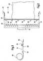
- Figure 1 shows an
agricultural combine 10 with achassis 12 and runningwheels 14 supporting it on the ground. Aheader 16 is used to take up crop and to conduct it to afeederhouse 18. The crop is conducted by thefeederhouse 18 to abeater 20. Thebeater 20 guides the crop upward through anintake transition region 22 to a rotary thresher andseparator 24. Although the invention is described on the example of a rotary combine, it can also be applied to other combines with an elevator for clean grain such as conventional straw walker machines. - The rotary thresher and
separator 24 comprises arotor housing 26 and arotor 28 arranged in therotor housing 26. The harvested crop enters therotor housing 26 through theintake transition region 22. The rotary thresher andseparator 24 threshes and separates the harvested crop. Grain and chaff fall through grates at the bottom of the rotor housing into acleaning system 34. Thecleaning system 34 removes the chaff and conducts the clean grain to agrain elevator 36 which conducts it in turn to a distributingscrew conveyor 38. The distributingscrew conveyor 38 deposits the clean grain in agrain tank 40. The clean grain in thegrain tank 40 can be unloaded through an unloadingscrew conveyor 42 into a trailer or truck. Threshed straw separated from the grain is conducted out of the rotary thresher andseparator 24 through an outlet to adischarge beater 46. Thedischarge beater 46 ejects the straw at the rear end of thecombine 10. - The operation of the
combine 10 is controlled from an operator'scab 48. Areceiver 50 for the reception of GPS signals (global positioning system) is attached above the operator'scab 48. Although it is at least in principle not necessary, when the accuracy of thereceiver 50 is sufficient, a speed sensor measuring the speed of thewheels 14 can be provided. Mounted on one side of thegrain elevator 36 is ameasurement capacitor 52 for measuring the moisture of the grain. Such a sensor is disclosed in DE 199 34 881 A. Aflow sensor 54 is located at the outlet of thegrain elevator 36. Theflow sensor 54 comprises an impeller plate mounted for rotation about a horizontal axis. Its deflection depends on the mass flow rate of the harvested crop. The deflection of the impeller plate is measured and thus data on the mass flow rate of the harvested grain is provided. Such a sensor is described in EP 0 853 234 A and the documents recited therein. - A
processor 56 located in the operator's cab 48 (or somewhere else on the combine 10) is connected to theGPS receiver 50, themeasurement capacitor 52, theflow sensor 54, and the speed sensor, when present. Theprocessor 56 is provided with an internal clock or receives external time signals, for example from thereceiver 50. Theprocessor 56 records the amount of harvested grain (measured by means of the flow sensor 54) and its moisture (measured by means of the measurement capacitor 52) dependent on the geographical position of the combine 10 (measured by means of the GPS receiver 50). Theprocessor 56 logs the data and produces a field summary. Thus, it is possible to create a yield map with the logged data, whereby other software is used. - In order to reduce errors during generating the yield map, the
header 16 is provided with a swath width sensing arrangement as shown in figure 2. The swath width sensing arrangement is submitting data to theprocessor 56, preferably by means of a bus, cables, optical fibres or electromagnetic waves. Thus, the actual width of the harvested swath is measured and considered when the yield map is generated. Theprocessor 56 thus considers when the swath of harvested crop is narrower than the active width of theheader 16, what might happen at an end of a field, or when thecombine 10 passes certain parts of a field a second time. Theprocessor 56 is capable of calculating a correct yield, since the latter depends on the amount of harvested grain and on the area on which it was harvested. This area depends on the swath width measured by the swath width sensing arrangement. - The
header 16 comprises between its side sheets acutter bar 58 for cutting the crop and anauger 60 for feeding the cut crop to the centre ofheader 16, where the crop is fed into thefeederhouse 18. At the front end of theside sheets 60,crop dividers 62 are located. Thedividers 62 are driven into the crop for splitting the crop sideways in front of theheader 16 before it is cut by thecutter bar 58. The latter defines the active width of the header. Although not shown, a conventional reel is usually located above thecutter bar 58. - In the header's 16 forward direction behind the
cutter bar 58, a number ofcrop presence sensors 64 for detecting the presence of crop are distributed of the width of theheader 16. Thecrop presence sensors 64 submit data containing an information whether crop is in their detection range (or not) to theprocessor 56. In the embodiment shown in figure 2, sixcrop presence sensors 64 are evenly distributed over the active width of theheader 16. A swath of crop to be harvested is indicated withreference numeral 66. Since in figure 2 the two uppermost crop presence sensors 64 (the most left sensors in the forward moving direction of the header 16) are not within the swath width, they will provide theprocessor 56 with a signal indicating the lack of crop. The threecrop presence sensors 64 shown in figure 2 below the two uppermostcrop presence sensors 64 are within the swath width. Thus, they submit a signal to theprocessor 56 indicating that crop is presently harvested at their location. Finally, the lowermostcrop presence sensor 64 shown at the bottom of figure 2 (the most right sensor in the forward moving direction of the header 16) is outside the swath width, as well, and submits a corresponding signal to theprocessor 56. - The
crop presence sensors 64 distributed over the active width of theheader 16 thus provide an information on the width of the harvested swath to theprocessor 56. According to the information provided by thecrop presence sensors 64, theprocessor 56 is operable to determine the width of theswath 66. Theprocessor 56 is also operable to detect whether harvesting is performed and thus crop is received at a11 (when at least onecrop presence sensor 64 gives an information that crop is present) or not (when nocrop presence sensor 64 submits data indicating that crop is present). Thus, a sensor for detecting the location of a reel is superfluous, and disadvantages of such sensors, as inaccuracy, are avoided. - In figure 3, a vertical cross sectional view of the
header 16 is given. Acrop presence sensor 64 is located at the rear end of thebed 74 of the table of theheader 16, and embedded into the surface of thebed 74. An alternative position of a crop presence sensor is indicated with 64'; thiscrop presence sensor 76 is embedded into astone ridge 76 at the forward end of thebed 74, behind theknives 58. - Preferably, the
crop presence sensors 64 are capacitive sensors. Such sensors are available from Carlo Gavazzi Industri A/S, OverHadstenvej 38, 8370 Hadsten, Denmark, order number EC 5525PPAP. An embodiment of a capacitivecrop presence sensor 64 is shown in more detail in figure 4. Thecrop presence sensor 64 is embedded into the upper surface of the table of theheader 16. Thecrop presence sensor 64 comprises aconductive foil 70 or plate mounted below an insulating (but not necessarily transparent)window 68 lying in the plane of the upper surface of thebed 74 of the table of theheader 16. Thefoil 70 is electrically connected to asignal processor 72. When crop is present above thewindow 68, the electric capacity of thefoil 70 measured against the header alters (increases). Thesignal processor 72 measures the electric capacity offoil 70. For example, thefoil 70 is part of an electric resonance circuit, the resonance frequency of which is measured. Any other measurement of the capacity is possible, as well. Thesignal processor 72 thus provides an information regarding the presence of crop in the crop presence sensor's 64 vicinity to theprocessor 56. - In order to avoid that crop resting on the
window 68 triggers thecrop presence sensor 64, producing an error of the yield map, thecrop presence sensor 64 is positioned on thebed 74 of the table of theheader 16. Hence crop remaining on thewindow 68 is normally wiped away by passing crop. Alternatively or additionally, the output of thesignal processor 72 is electrically processed removing the effect of any stationary material actuating thecrop presence sensors 64. Thus, a time derivation of a value representing the capacity offoil 70 can be obtained and further processed. - In figure 5, another embodiment of a capacitive
crop presence sensor 64 is given. It is located above thesurface 74 of the table of the header. Aramp 78 in forward direction before and behind thecrop presence sensor 64 keeps the surface of the crop presence sensor free of stationary material. - Figure 6 shows a third embodiment of a
crop presence sensor 64, located below thestone ridge 76, and figure 7 represents a fourth embodiment of acrop presence sensor 64, integrated into thestone ridge 76, like the crop presence sensor 64' in figure 3. The elements of thecrop presence sensors 64 of figures 5 to 7 are the same as those of the sensor shown in figure 4. - For either
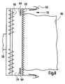
position 64 or 64' shown in figure 3, it is possible to make use of separatecrop presence sensors 64 as indicated in figure 2. In another embodiment, as shown in figure 8, two arrays ofcrop presence sensors 64 are provided. A first array ofcrop presence sensors 64 is placed at the left-hand edge of the table. A second (optional) array ofcrop presence sensors 64 is placed against the right-hand end of the table. This arrangement of sensors operates like the one disclosed in figure 2, except when the swath width does not cover the sensor array or arrays theprocessor 56 records the width as zero. Both arrays ofcrop presence sensors 64 preferably cover a width of 0,2 to 1 m. Software is used to insert the missing data on the yield map by interpreting between adjacent runs where the table was nearly full. Thus, the yield is known more accurately than with the embodiment of figure 2, although a similar number ofcrop sensors 64 is used.
Claims (8)
- An agricultural machine having a crop receiving and/or processing means arranged to receive and/or process crop, the machine comprising a crop width measuring means for measuring the width of crop received and/or processed by the crop receiving and/or processing means, the crop width measuring means comprising at least two crop presence sensors (64) having a detection range and providing data containing an information whether crop is in their detection range, wherein a plurality of the crop presence sensors (64) are distributed over the width of the crop receiving and/or processing means of the agricultural machine,characterised in that the crop presence sensors (64) are located in the plane of the surface of the crop receiving and/or processing means such that moving crop removes any stationary crop from the crop presence sensors (64).
- An agricultural machine according to claim 1,characterised in that it is a header.
- An agricultural machine according to claim 1 or 2,characterised in that at least one crop presence sensor (64) is connected to a signal processor (72) which electronically processes the signal of the crop presence sensor (64) removing the effect of any stationary crop actuating the crop presence sensor (64).
- An agricultural machine according to one of claims 1 to 3,characterised in that at least one of the crop presence sensors (64) is a capacitive sensor.
- An agricultural machine according to one of claims 1 to 4 in combination with an apparatus for collecting data concerning crop received and/or processed by the agricultural machine, the apparatus for collecting data comprising a location and/or distance measuring means for monitoring the geographical position of the agricultural machine in a field and/or the distance the machine has covered, a crop width measuring means for measuring the width of crop received and/or processed by the agricultural machine, and a processor (56) receiving data from the location and/or distance measuring means and from the crop width measuring means, wherein the processor is operable to establish a value which is dependent on the area from which crop was received and/or processed.
- An agricultural machine according to claim 5,characterised in that it comprises a parameter measuring means for measuring a parameter of the received crop and that the processor (56) is operable to establish a map representative of a variable derived from the parameter at several locations of the field.
- An agricultural machine according to claim 5 or 6,characterised in that the processor (56) determines according to the signal of the crop presence sensors (64) whether crop is received and/or cutting is performed at all.
- An agricultural machine according to one of claims 5 to 7, wherein the agricultural machine is a combine and the crop presence sensors (64) are distributed over the width of a cutter bar (58) of a header (16) of the combine.
Priority Applications (8)
| Application Number | Priority Date | Filing Date | Title |
|---|---|---|---|
| DE60118518TDE60118518T2 (en) | 2001-03-08 | 2001-03-08 | Means for measuring the cutting width of crop |
| EP01105749AEP1238579B1 (en) | 2001-03-08 | 2001-03-08 | Crop width measuring means |
| AT01105749TATE322151T1 (en) | 2001-03-08 | 2001-03-08 | MEANS FOR MEASURING THE CUTTING WIDTH OF CROP |
| US10/090,233US6668223B2 (en) | 2001-03-08 | 2002-03-04 | Crop width measuring apparatus |
| AU21289/02AAU784164B2 (en) | 2001-03-08 | 2002-03-07 | Crop width measuring apparatus |
| CA002375009ACA2375009C (en) | 2001-03-08 | 2002-03-07 | Crop width measuring apparatus |
| ARP020100847AAR033432A1 (en) | 2001-03-08 | 2002-03-08 | CULTURE WIDTH METER DEVICE |
| BRPI0200716-9ABR0200716B1 (en) | 2001-03-08 | 2002-03-08 | width measurement set of a vintage. |
Applications Claiming Priority (1)
| Application Number | Priority Date | Filing Date | Title |
|---|---|---|---|
| EP01105749AEP1238579B1 (en) | 2001-03-08 | 2001-03-08 | Crop width measuring means |
Publications (2)
| Publication Number | Publication Date |
|---|---|
| EP1238579A1 EP1238579A1 (en) | 2002-09-11 |
| EP1238579B1true EP1238579B1 (en) | 2006-04-05 |
Family
ID=8176717
Family Applications (1)
| Application Number | Title | Priority Date | Filing Date |
|---|---|---|---|
| EP01105749AExpired - LifetimeEP1238579B1 (en) | 2001-03-08 | 2001-03-08 | Crop width measuring means |
Country Status (8)
| Country | Link |
|---|---|
| US (1) | US6668223B2 (en) |
| EP (1) | EP1238579B1 (en) |
| AR (1) | AR033432A1 (en) |
| AT (1) | ATE322151T1 (en) |
| AU (1) | AU784164B2 (en) |
| BR (1) | BR0200716B1 (en) |
| CA (1) | CA2375009C (en) |
| DE (1) | DE60118518T2 (en) |
Families Citing this family (90)
| Publication number | Priority date | Publication date | Assignee | Title |
|---|---|---|---|---|
| GB0028665D0 (en)* | 2000-11-24 | 2001-01-10 | Ford New Holland Nv | A method of estimating crop yields |
| DE102008032191A1 (en)* | 2008-07-09 | 2010-01-14 | Claas Selbstfahrende Erntemaschinen Gmbh | Self-propelled harvester |
| EP2529610A1 (en)* | 2011-05-30 | 2012-12-05 | Agri-Esprit SAS | Method for harvest monitoring |
| BR112014012224B1 (en) | 2011-11-22 | 2019-04-09 | Precision Planting Llc | METHOD FOR MEASURING A TALO DIAMETER ACCORDING TO AN AGRICULTURAL HARVEST THROUGH A FIELD, AND A TALO SENSOR SYSTEM FOR USE WITH AN AGRICULTURAL HARVESTER WHILE THE HARVEST THREADS A FIELD |
| US9693503B2 (en) | 2013-02-20 | 2017-07-04 | Deere & Company | Crop sensing |
| US11212962B2 (en) | 2013-02-20 | 2022-01-04 | Deere & Company | Field condition determination |
| US9066465B2 (en) | 2013-02-20 | 2015-06-30 | Deere & Company | Soil compaction reduction system and method |
| US9668420B2 (en)* | 2013-02-20 | 2017-06-06 | Deere & Company | Crop sensing display |
| US9282693B2 (en) | 2013-02-20 | 2016-03-15 | Deere & Company | Data encoding with planting attributes |
| US10178828B2 (en) | 2013-02-20 | 2019-01-15 | Deere & Company | Per plant crop sensing resolution |
| CN103115592B (en)* | 2013-03-01 | 2016-03-30 | 潍坊市计量测试所 | Ultrasound wave cropper Mu measuring device |
| BE1021107B1 (en)* | 2013-10-28 | 2016-01-18 | Cnh Industrial Belgium Nv | SWATH SENSOR FOR FIELD FORMER |
| US10225984B2 (en)* | 2014-03-06 | 2019-03-12 | Raven Industries, Inc. | System and method for sensing an edge |
| US9317979B2 (en)* | 2014-05-01 | 2016-04-19 | Deere & Company | Crop density map using row sensors |
| US10126282B2 (en) | 2014-09-23 | 2018-11-13 | Deere & Company | Yield estimation |
| US9903979B2 (en) | 2014-09-23 | 2018-02-27 | Deere & Company | Yield estimation |
| CN105052369B (en)* | 2015-08-13 | 2017-05-31 | 江苏农牧科技职业学院 | The control method of the advance acquisition means of combined harvester solid particle |
| US10188037B2 (en) | 2015-09-24 | 2019-01-29 | Deere & Company | Yield estimation |
| US10858801B2 (en)* | 2017-11-30 | 2020-12-08 | Caterpillar Inc. | System for controlling operation of a machine |
| JP2019170315A (en)* | 2018-03-29 | 2019-10-10 | 株式会社クボタ | Combine |
| US11064653B2 (en) | 2018-06-18 | 2021-07-20 | Ag Leader Technology | Agricultural systems having stalk sensors and data visualization systems and related devices and methods |
| US11419261B2 (en)* | 2018-06-25 | 2022-08-23 | Deere & Company | Prescription cover crop seeding with combine |
| US11957072B2 (en) | 2020-02-06 | 2024-04-16 | Deere & Company | Pre-emergence weed detection and mitigation system |
| US11589509B2 (en) | 2018-10-26 | 2023-02-28 | Deere & Company | Predictive machine characteristic map generation and control system |
| US11079725B2 (en) | 2019-04-10 | 2021-08-03 | Deere & Company | Machine control using real-time model |
| US11467605B2 (en) | 2019-04-10 | 2022-10-11 | Deere & Company | Zonal machine control |
| US11641800B2 (en) | 2020-02-06 | 2023-05-09 | Deere & Company | Agricultural harvesting machine with pre-emergence weed detection and mitigation system |
| US11240961B2 (en) | 2018-10-26 | 2022-02-08 | Deere & Company | Controlling a harvesting machine based on a geo-spatial representation indicating where the harvesting machine is likely to reach capacity |
| US11178818B2 (en) | 2018-10-26 | 2021-11-23 | Deere & Company | Harvesting machine control system with fill level processing based on yield data |
| US12069978B2 (en) | 2018-10-26 | 2024-08-27 | Deere & Company | Predictive environmental characteristic map generation and control system |
| US11672203B2 (en) | 2018-10-26 | 2023-06-13 | Deere & Company | Predictive map generation and control |
| US11653588B2 (en) | 2018-10-26 | 2023-05-23 | Deere & Company | Yield map generation and control system |
| US10966369B2 (en) | 2018-10-31 | 2021-04-06 | Cnh Industrial America Llc | System and method for calibrating alignment of work vehicles |
| US11399462B2 (en) | 2018-10-31 | 2022-08-02 | Cnh Industrial America Llc | System and method for calibrating alignment of work vehicles |
| JP7174489B2 (en)* | 2018-12-21 | 2022-11-17 | 株式会社クボタ | combine |
| CN209605915U (en)* | 2018-12-28 | 2019-11-08 | 厦门帮众科技有限公司 | A kind of accurate measuring device |
| US11297768B2 (en) | 2019-02-25 | 2022-04-12 | Ag Leader Technology | Vision based stalk sensors and associated systems and methods |
| US11234366B2 (en) | 2019-04-10 | 2022-02-01 | Deere & Company | Image selection for machine control |
| US20210329838A1 (en)* | 2019-09-04 | 2021-10-28 | Ag Leader Technology | Apparatus, Systems And Methods For Stalk Sensing |
| US12035648B2 (en) | 2020-02-06 | 2024-07-16 | Deere & Company | Predictive weed map generation and control system |
| US12225846B2 (en) | 2020-02-06 | 2025-02-18 | Deere & Company | Machine control using a predictive map |
| US12329148B2 (en) | 2020-02-06 | 2025-06-17 | Deere & Company | Predictive weed map and material application machine control |
| US11477940B2 (en) | 2020-03-26 | 2022-10-25 | Deere & Company | Mobile work machine control based on zone parameter modification |
| US11659787B2 (en)* | 2020-04-03 | 2023-05-30 | Cnh Industrial America Llc | Harvesting head reel-crop engagement |
| US20210315160A1 (en) | 2020-04-08 | 2021-10-14 | Ag Leader Technology | Devices, Systems, And Methods For Corn Headers |
| US11678607B2 (en) | 2020-07-01 | 2023-06-20 | Ag Leader Technology | Apparatus, systems and methods for eliminating cross-track error |
| US12414505B2 (en) | 2020-09-04 | 2025-09-16 | Ag Leader Technology | Harvesting system for row-by-row control of a harvester |
| US12069986B2 (en) | 2020-10-09 | 2024-08-27 | Deere & Company | Map generation and control system |
| US11727680B2 (en) | 2020-10-09 | 2023-08-15 | Deere & Company | Predictive map generation based on seeding characteristics and control |
| US20220110238A1 (en) | 2020-10-09 | 2022-04-14 | Deere & Company | Machine control using a predictive map |
| US11874669B2 (en) | 2020-10-09 | 2024-01-16 | Deere & Company | Map generation and control system |
| US12422847B2 (en) | 2020-10-09 | 2025-09-23 | Deere & Company | Predictive agricultural model and map generation |
| US12419220B2 (en) | 2020-10-09 | 2025-09-23 | Deere & Company | Predictive map generation and control system |
| US11675354B2 (en) | 2020-10-09 | 2023-06-13 | Deere & Company | Machine control using a predictive map |
| US11844311B2 (en) | 2020-10-09 | 2023-12-19 | Deere & Company | Machine control using a predictive map |
| US11650587B2 (en) | 2020-10-09 | 2023-05-16 | Deere & Company | Predictive power map generation and control system |
| US11927459B2 (en) | 2020-10-09 | 2024-03-12 | Deere & Company | Machine control using a predictive map |
| US11711995B2 (en) | 2020-10-09 | 2023-08-01 | Deere & Company | Machine control using a predictive map |
| US11474523B2 (en) | 2020-10-09 | 2022-10-18 | Deere & Company | Machine control using a predictive speed map |
| US12386354B2 (en) | 2020-10-09 | 2025-08-12 | Deere & Company | Predictive power map generation and control system |
| US12178158B2 (en) | 2020-10-09 | 2024-12-31 | Deere & Company | Predictive map generation and control system for an agricultural work machine |
| US11849672B2 (en) | 2020-10-09 | 2023-12-26 | Deere & Company | Machine control using a predictive map |
| US11864483B2 (en) | 2020-10-09 | 2024-01-09 | Deere & Company | Predictive map generation and control system |
| US11592822B2 (en) | 2020-10-09 | 2023-02-28 | Deere & Company | Machine control using a predictive map |
| US20220110258A1 (en) | 2020-10-09 | 2022-04-14 | Deere & Company | Map generation and control system |
| US11845449B2 (en) | 2020-10-09 | 2023-12-19 | Deere & Company | Map generation and control system |
| US11635765B2 (en) | 2020-10-09 | 2023-04-25 | Deere & Company | Crop state map generation and control system |
| US11849671B2 (en) | 2020-10-09 | 2023-12-26 | Deere & Company | Crop state map generation and control system |
| US11946747B2 (en) | 2020-10-09 | 2024-04-02 | Deere & Company | Crop constituent map generation and control system |
| US11983009B2 (en) | 2020-10-09 | 2024-05-14 | Deere & Company | Map generation and control system |
| US11889788B2 (en) | 2020-10-09 | 2024-02-06 | Deere & Company | Predictive biomass map generation and control |
| US11825768B2 (en) | 2020-10-09 | 2023-11-28 | Deere & Company | Machine control using a predictive map |
| US11871697B2 (en) | 2020-10-09 | 2024-01-16 | Deere & Company | Crop moisture map generation and control system |
| US11895948B2 (en) | 2020-10-09 | 2024-02-13 | Deere & Company | Predictive map generation and control based on soil properties |
| US12013245B2 (en) | 2020-10-09 | 2024-06-18 | Deere & Company | Predictive map generation and control system |
| US11889787B2 (en) | 2020-10-09 | 2024-02-06 | Deere & Company | Predictive speed map generation and control system |
| US12250905B2 (en) | 2020-10-09 | 2025-03-18 | Deere & Company | Machine control using a predictive map |
| US12029154B2 (en)* | 2021-01-05 | 2024-07-09 | Cnh Industrial America Llc | Mower-conditioner machine for sensing moisture content of crop material |
| US12127500B2 (en) | 2021-01-27 | 2024-10-29 | Deere & Company | Machine control using a map with regime zones |
| US12229886B2 (en) | 2021-10-01 | 2025-02-18 | Deere & Company | Historical crop state model, predictive crop state map generation and control system |
| US12310286B2 (en) | 2021-12-14 | 2025-05-27 | Deere & Company | Crop constituent sensing |
| US12302791B2 (en) | 2021-12-20 | 2025-05-20 | Deere & Company | Crop constituents, predictive mapping, and agricultural harvester control |
| US12245549B2 (en) | 2022-01-11 | 2025-03-11 | Deere & Company | Predictive response map generation and control system |
| US12082531B2 (en) | 2022-01-26 | 2024-09-10 | Deere & Company | Systems and methods for predicting material dynamics |
| US12295288B2 (en) | 2022-04-05 | 2025-05-13 | Deere &Company | Predictive machine setting map generation and control system |
| US12058951B2 (en) | 2022-04-08 | 2024-08-13 | Deere & Company | Predictive nutrient map and control |
| US12358493B2 (en) | 2022-04-08 | 2025-07-15 | Deere & Company | Systems and methods for predictive power requirements and control |
| US12284934B2 (en) | 2022-04-08 | 2025-04-29 | Deere & Company | Systems and methods for predictive tractive characteristics and control |
| US12298767B2 (en) | 2022-04-08 | 2025-05-13 | Deere & Company | Predictive material consumption map and control |
| DE102023109981A1 (en) | 2023-04-20 | 2024-10-24 | Deere & Company | Method for generating an electronic yield map of a field |
Family Cites Families (12)
| Publication number | Priority date | Publication date | Assignee | Title |
|---|---|---|---|---|
| SU676216A1 (en)* | 1976-01-13 | 1979-07-30 | Завод "Бежецксельмаш" | Apparatus for determining the productivity of harvesting machines |
| DE2608049A1 (en)* | 1976-02-27 | 1977-09-01 | Claas Maschf Gmbh Geb | METHOD AND DEVICE FOR MEASURING PLANT DENSITY FOR THE CONTROL OF HARVESTING MACHINERY |
| US4918441A (en)* | 1988-12-22 | 1990-04-17 | Ford New Holland, Inc. | Non-contact sensing unit for row crop harvester guidance system |
| DE4041995A1 (en) | 1990-12-27 | 1992-07-02 | Mech Landwirtsch Forschzent | Monitoring and regulating silage cutter - using processor to monitor cutter speed and flow-rate of crop and pressure difference in crop duct |
| US5524424A (en) | 1994-12-13 | 1996-06-11 | Case Corporation | Electronic area counter for a combine |
| US5606504A (en)* | 1995-02-17 | 1997-02-25 | Lockheed Martin Corporation | Crop swath-width measurement using acoustic transducers |
| DE19543343C5 (en) | 1995-11-22 | 2007-01-18 | Claas Kgaa Mbh | Agricultural Baler |
| GB2321111A (en) | 1997-01-11 | 1998-07-15 | Ford New Holland Nv | Member for mass flow measurement |
| US5995894A (en)* | 1997-05-27 | 1999-11-30 | Case Corporation | System for analyzing spatially-variable harvest data by pass |
| GB9811024D0 (en)* | 1998-05-22 | 1998-07-22 | Ford New Holland Nv | Harvester with crop flow rate sensor |
| GB9811177D0 (en)* | 1998-05-26 | 1998-07-22 | Ford New Holland Nv | Methods for generating field maps |
| DE19934881A1 (en) | 1999-07-24 | 2001-01-25 | Deere & Co | Device for measuring the moisture of crops |
- 2001
- 2001-03-08EPEP01105749Apatent/EP1238579B1/ennot_activeExpired - Lifetime
- 2001-03-08ATAT01105749Tpatent/ATE322151T1/ennot_activeIP Right Cessation
- 2001-03-08DEDE60118518Tpatent/DE60118518T2/ennot_activeExpired - Fee Related
- 2002
- 2002-03-04USUS10/090,233patent/US6668223B2/ennot_activeExpired - Lifetime
- 2002-03-07AUAU21289/02Apatent/AU784164B2/ennot_activeCeased
- 2002-03-07CACA002375009Apatent/CA2375009C/ennot_activeExpired - Fee Related
- 2002-03-08BRBRPI0200716-9Apatent/BR0200716B1/ennot_activeIP Right Cessation
- 2002-03-08ARARP020100847Apatent/AR033432A1/enactiveIP Right Grant
Also Published As
| Publication number | Publication date |
|---|---|
| DE60118518D1 (en) | 2006-05-18 |
| CA2375009A1 (en) | 2002-09-08 |
| US6668223B2 (en) | 2003-12-23 |
| AU2128902A (en) | 2002-09-12 |
| BR0200716B1 (en) | 2010-11-03 |
| BR0200716A (en) | 2002-12-03 |
| AR033432A1 (en) | 2003-12-17 |
| EP1238579A1 (en) | 2002-09-11 |
| AU784164B2 (en) | 2006-02-16 |
| CA2375009C (en) | 2005-10-11 |
| ATE322151T1 (en) | 2006-04-15 |
| DE60118518T2 (en) | 2006-12-14 |
| US20020173893A1 (en) | 2002-11-21 |
Similar Documents
| Publication | Publication Date | Title |
|---|---|---|
| EP1238579B1 (en) | Crop width measuring means | |
| US6185990B1 (en) | Method of measuring crop humidity in a harvester | |
| CA2422280C (en) | Device for detecting the presence of a crop flow in a harvesting machine | |
| EP3008990B1 (en) | Yield estimation | |
| EP3092886B1 (en) | Combine harvester combining row crop guidance and plant attribute measurement | |
| EP2944179B1 (en) | Multi-sensor crop yield determination | |
| US6584390B2 (en) | System for measuring the amount of crop to be harvested | |
| EP1180925B1 (en) | Method of collecting data for use in yield mapping from a harvesting machine and an apparatus therefor | |
| CA2182989C (en) | Grain moisture sensor | |
| EP4027770B1 (en) | Harvesting headers having leading sensors, agricultural machines carrying such headers, and related methods | |
| US5685772A (en) | Acoustic volume and torque weight sensor | |
| EP1545186A1 (en) | Methods of optimising stochastic processing parameters in crop harvesting machines | |
| US20230189708A1 (en) | Sensing array for grain tank | |
| EP4088560A1 (en) | Grain loss sensing | |
| US20070130900A1 (en) | Harvesting machine with a measuring device for capturing the throughput of collected and/or processed crops | |
| EP4201189A1 (en) | Harvester header with radar arrangement | |
| EP3000304B1 (en) | Aggregate yield allocation | |
| US20240341222A1 (en) | Agricultural header with a pivot sensor linkage | |
| CA2530644C (en) | Harvesting machine with a measuring device for capturing the throughput of collected and/or processed crops | |
| BR102019000830B1 (en) | HARVESTER AND METHOD FOR CONTROLLING A HARVESTER |
Legal Events
| Date | Code | Title | Description |
|---|---|---|---|
| PUAI | Public reference made under article 153(3) epc to a published international application that has entered the european phase | Free format text:ORIGINAL CODE: 0009012 | |
| AK | Designated contracting states | Kind code of ref document:A1 Designated state(s):AT BE CH CY DE DK ES FI FR GB GR IE IT LI LU MC NL PT SE TR | |
| AX | Request for extension of the european patent | Free format text:AL;LT;LV;MK;RO;SI | |
| 17P | Request for examination filed | Effective date:20030311 | |
| AKX | Designation fees paid | Designated state(s):AT BE CH CY DE DK ES FI FR GB GR IE IT LI LU MC NL PT SE TR | |
| 17Q | First examination report despatched | Effective date:20040909 | |
| GRAP | Despatch of communication of intention to grant a patent | Free format text:ORIGINAL CODE: EPIDOSNIGR1 | |
| GRAS | Grant fee paid | Free format text:ORIGINAL CODE: EPIDOSNIGR3 | |
| GRAA | (expected) grant | Free format text:ORIGINAL CODE: 0009210 | |
| AK | Designated contracting states | Kind code of ref document:B1 Designated state(s):AT BE CH CY DE DK ES FI FR GB GR IE IT LI LU MC NL PT SE TR | |
| PG25 | Lapsed in a contracting state [announced via postgrant information from national office to epo] | Ref country code:IT Free format text:LAPSE BECAUSE OF FAILURE TO SUBMIT A TRANSLATION OF THE DESCRIPTION OR TO PAY THE FEE WITHIN THE PRESCRIBED TIME-LIMIT;WARNING: LAPSES OF ITALIAN PATENTS WITH EFFECTIVE DATE BEFORE 2007 MAY HAVE OCCURRED AT ANY TIME BEFORE 2007. THE CORRECT EFFECTIVE DATE MAY BE DIFFERENT FROM THE ONE RECORDED. Effective date:20060405 Ref country code:FI Free format text:LAPSE BECAUSE OF FAILURE TO SUBMIT A TRANSLATION OF THE DESCRIPTION OR TO PAY THE FEE WITHIN THE PRESCRIBED TIME-LIMIT Effective date:20060405 Ref country code:LI Free format text:LAPSE BECAUSE OF FAILURE TO SUBMIT A TRANSLATION OF THE DESCRIPTION OR TO PAY THE FEE WITHIN THE PRESCRIBED TIME-LIMIT Effective date:20060405 Ref country code:CH Free format text:LAPSE BECAUSE OF FAILURE TO SUBMIT A TRANSLATION OF THE DESCRIPTION OR TO PAY THE FEE WITHIN THE PRESCRIBED TIME-LIMIT Effective date:20060405 Ref country code:AT Free format text:LAPSE BECAUSE OF FAILURE TO SUBMIT A TRANSLATION OF THE DESCRIPTION OR TO PAY THE FEE WITHIN THE PRESCRIBED TIME-LIMIT Effective date:20060405 Ref country code:NL Free format text:LAPSE BECAUSE OF FAILURE TO SUBMIT A TRANSLATION OF THE DESCRIPTION OR TO PAY THE FEE WITHIN THE PRESCRIBED TIME-LIMIT Effective date:20060405 | |
| REG | Reference to a national code | Ref country code:GB Ref legal event code:FG4D | |
| REG | Reference to a national code | Ref country code:CH Ref legal event code:EP | |
| REG | Reference to a national code | Ref country code:IE Ref legal event code:FG4D | |
| REF | Corresponds to: | Ref document number:60118518 Country of ref document:DE Date of ref document:20060518 Kind code of ref document:P | |
| PG25 | Lapsed in a contracting state [announced via postgrant information from national office to epo] | Ref country code:DK Free format text:LAPSE BECAUSE OF FAILURE TO SUBMIT A TRANSLATION OF THE DESCRIPTION OR TO PAY THE FEE WITHIN THE PRESCRIBED TIME-LIMIT Effective date:20060705 Ref country code:SE Free format text:LAPSE BECAUSE OF FAILURE TO SUBMIT A TRANSLATION OF THE DESCRIPTION OR TO PAY THE FEE WITHIN THE PRESCRIBED TIME-LIMIT Effective date:20060705 | |
| PG25 | Lapsed in a contracting state [announced via postgrant information from national office to epo] | Ref country code:ES Free format text:LAPSE BECAUSE OF FAILURE TO SUBMIT A TRANSLATION OF THE DESCRIPTION OR TO PAY THE FEE WITHIN THE PRESCRIBED TIME-LIMIT Effective date:20060716 | |
| PG25 | Lapsed in a contracting state [announced via postgrant information from national office to epo] | Ref country code:PT Free format text:LAPSE BECAUSE OF FAILURE TO SUBMIT A TRANSLATION OF THE DESCRIPTION OR TO PAY THE FEE WITHIN THE PRESCRIBED TIME-LIMIT Effective date:20060905 | |
| NLV1 | Nl: lapsed or annulled due to failure to fulfill the requirements of art. 29p and 29m of the patents act | ||
| REG | Reference to a national code | Ref country code:CH Ref legal event code:PL | |
| ET | Fr: translation filed | ||
| PLBE | No opposition filed within time limit | Free format text:ORIGINAL CODE: 0009261 | |
| STAA | Information on the status of an ep patent application or granted ep patent | Free format text:STATUS: NO OPPOSITION FILED WITHIN TIME LIMIT | |
| 26N | No opposition filed | Effective date:20070108 | |
| PGFP | Annual fee paid to national office [announced via postgrant information from national office to epo] | Ref country code:GB Payment date:20070327 Year of fee payment:7 | |
| PGFP | Annual fee paid to national office [announced via postgrant information from national office to epo] | Ref country code:IT Payment date:20070517 Year of fee payment:7 | |
| PG25 | Lapsed in a contracting state [announced via postgrant information from national office to epo] | Ref country code:MC Free format text:LAPSE BECAUSE OF NON-PAYMENT OF DUE FEES Effective date:20070331 Ref country code:IE Free format text:LAPSE BECAUSE OF NON-PAYMENT OF DUE FEES Effective date:20070308 | |
| PG25 | Lapsed in a contracting state [announced via postgrant information from national office to epo] | Ref country code:GR Free format text:LAPSE BECAUSE OF FAILURE TO SUBMIT A TRANSLATION OF THE DESCRIPTION OR TO PAY THE FEE WITHIN THE PRESCRIBED TIME-LIMIT Effective date:20060706 | |
| PGFP | Annual fee paid to national office [announced via postgrant information from national office to epo] | Ref country code:FR Payment date:20070319 Year of fee payment:7 | |
| GBPC | Gb: european patent ceased through non-payment of renewal fee | Effective date:20080308 | |
| REG | Reference to a national code | Ref country code:FR Ref legal event code:ST Effective date:20081125 | |
| PG25 | Lapsed in a contracting state [announced via postgrant information from national office to epo] | Ref country code:FR Free format text:LAPSE BECAUSE OF NON-PAYMENT OF DUE FEES Effective date:20080331 | |
| PG25 | Lapsed in a contracting state [announced via postgrant information from national office to epo] | Ref country code:GB Free format text:LAPSE BECAUSE OF NON-PAYMENT OF DUE FEES Effective date:20080308 | |
| PG25 | Lapsed in a contracting state [announced via postgrant information from national office to epo] | Ref country code:CY Free format text:LAPSE BECAUSE OF FAILURE TO SUBMIT A TRANSLATION OF THE DESCRIPTION OR TO PAY THE FEE WITHIN THE PRESCRIBED TIME-LIMIT Effective date:20060405 Ref country code:LU Free format text:LAPSE BECAUSE OF NON-PAYMENT OF DUE FEES Effective date:20070308 Ref country code:IT Free format text:LAPSE BECAUSE OF NON-PAYMENT OF DUE FEES Effective date:20080308 | |
| PGFP | Annual fee paid to national office [announced via postgrant information from national office to epo] | Ref country code:DE Payment date:20090220 Year of fee payment:9 | |
| PG25 | Lapsed in a contracting state [announced via postgrant information from national office to epo] | Ref country code:TR Free format text:LAPSE BECAUSE OF FAILURE TO SUBMIT A TRANSLATION OF THE DESCRIPTION OR TO PAY THE FEE WITHIN THE PRESCRIBED TIME-LIMIT Effective date:20060405 | |
| PGFP | Annual fee paid to national office [announced via postgrant information from national office to epo] | Ref country code:BE Payment date:20090430 Year of fee payment:9 | |
| BERE | Be: lapsed | Owner name:*DEERE & CY Effective date:20100331 | |
| PG25 | Lapsed in a contracting state [announced via postgrant information from national office to epo] | Ref country code:DE Free format text:LAPSE BECAUSE OF NON-PAYMENT OF DUE FEES Effective date:20101001 Ref country code:BE Free format text:LAPSE BECAUSE OF NON-PAYMENT OF DUE FEES Effective date:20100331 |