EP1235538B1 - Optimization of ablation correction of an optical system - Google Patents
Optimization of ablation correction of an optical systemDownload PDFInfo
- Publication number
- EP1235538B1 EP1235538B1EP01923348AEP01923348AEP1235538B1EP 1235538 B1EP1235538 B1EP 1235538B1EP 01923348 AEP01923348 AEP 01923348AEP 01923348 AEP01923348 AEP 01923348AEP 1235538 B1EP1235538 B1EP 1235538B1
- Authority
- EP
- European Patent Office
- Prior art keywords
- eye
- optical
- wavefront
- ablation
- corneal
- Prior art date
- Legal status (The legal status is an assumption and is not a legal conclusion. Google has not performed a legal analysis and makes no representation as to the accuracy of the status listed.)
- Expired - Lifetime
Links
Images


Classifications
- A—HUMAN NECESSITIES
- A61—MEDICAL OR VETERINARY SCIENCE; HYGIENE
- A61B—DIAGNOSIS; SURGERY; IDENTIFICATION
- A61B3/00—Apparatus for testing the eyes; Instruments for examining the eyes
- A61B3/10—Objective types, i.e. instruments for examining the eyes independent of the patients' perceptions or reactions
- A61B3/1015—Objective types, i.e. instruments for examining the eyes independent of the patients' perceptions or reactions for wavefront analysis
- A—HUMAN NECESSITIES
- A61—MEDICAL OR VETERINARY SCIENCE; HYGIENE
- A61F—FILTERS IMPLANTABLE INTO BLOOD VESSELS; PROSTHESES; DEVICES PROVIDING PATENCY TO, OR PREVENTING COLLAPSING OF, TUBULAR STRUCTURES OF THE BODY, e.g. STENTS; ORTHOPAEDIC, NURSING OR CONTRACEPTIVE DEVICES; FOMENTATION; TREATMENT OR PROTECTION OF EYES OR EARS; BANDAGES, DRESSINGS OR ABSORBENT PADS; FIRST-AID KITS
- A61F9/00—Methods or devices for treatment of the eyes; Devices for putting in contact-lenses; Devices to correct squinting; Apparatus to guide the blind; Protective devices for the eyes, carried on the body or in the hand
- A61F9/007—Methods or devices for eye surgery
- A61F9/008—Methods or devices for eye surgery using laser
- A61F9/00802—Methods or devices for eye surgery using laser for photoablation
- A61F9/00804—Refractive treatments
- A61F9/00806—Correction of higher orders
- A—HUMAN NECESSITIES
- A61—MEDICAL OR VETERINARY SCIENCE; HYGIENE
- A61B—DIAGNOSIS; SURGERY; IDENTIFICATION
- A61B5/00—Measuring for diagnostic purposes; Identification of persons
- A61B5/103—Measuring devices for testing the shape, pattern, colour, size or movement of the body or parts thereof, for diagnostic purposes
- A—HUMAN NECESSITIES
- A61—MEDICAL OR VETERINARY SCIENCE; HYGIENE
- A61F—FILTERS IMPLANTABLE INTO BLOOD VESSELS; PROSTHESES; DEVICES PROVIDING PATENCY TO, OR PREVENTING COLLAPSING OF, TUBULAR STRUCTURES OF THE BODY, e.g. STENTS; ORTHOPAEDIC, NURSING OR CONTRACEPTIVE DEVICES; FOMENTATION; TREATMENT OR PROTECTION OF EYES OR EARS; BANDAGES, DRESSINGS OR ABSORBENT PADS; FIRST-AID KITS
- A61F9/00—Methods or devices for treatment of the eyes; Devices for putting in contact-lenses; Devices to correct squinting; Apparatus to guide the blind; Protective devices for the eyes, carried on the body or in the hand
- A61F9/007—Methods or devices for eye surgery
- A61F9/008—Methods or devices for eye surgery using laser
- A61F2009/00844—Feedback systems
- A61F2009/00846—Eyetracking
- A—HUMAN NECESSITIES
- A61—MEDICAL OR VETERINARY SCIENCE; HYGIENE
- A61F—FILTERS IMPLANTABLE INTO BLOOD VESSELS; PROSTHESES; DEVICES PROVIDING PATENCY TO, OR PREVENTING COLLAPSING OF, TUBULAR STRUCTURES OF THE BODY, e.g. STENTS; ORTHOPAEDIC, NURSING OR CONTRACEPTIVE DEVICES; FOMENTATION; TREATMENT OR PROTECTION OF EYES OR EARS; BANDAGES, DRESSINGS OR ABSORBENT PADS; FIRST-AID KITS
- A61F9/00—Methods or devices for treatment of the eyes; Devices for putting in contact-lenses; Devices to correct squinting; Apparatus to guide the blind; Protective devices for the eyes, carried on the body or in the hand
- A61F9/007—Methods or devices for eye surgery
- A61F9/008—Methods or devices for eye surgery using laser
- A61F2009/00844—Feedback systems
- A61F2009/00848—Feedback systems based on wavefront
- A—HUMAN NECESSITIES
- A61—MEDICAL OR VETERINARY SCIENCE; HYGIENE
- A61F—FILTERS IMPLANTABLE INTO BLOOD VESSELS; PROSTHESES; DEVICES PROVIDING PATENCY TO, OR PREVENTING COLLAPSING OF, TUBULAR STRUCTURES OF THE BODY, e.g. STENTS; ORTHOPAEDIC, NURSING OR CONTRACEPTIVE DEVICES; FOMENTATION; TREATMENT OR PROTECTION OF EYES OR EARS; BANDAGES, DRESSINGS OR ABSORBENT PADS; FIRST-AID KITS
- A61F9/00—Methods or devices for treatment of the eyes; Devices for putting in contact-lenses; Devices to correct squinting; Apparatus to guide the blind; Protective devices for the eyes, carried on the body or in the hand
- A61F9/007—Methods or devices for eye surgery
- A61F9/008—Methods or devices for eye surgery using laser
- A61F2009/00855—Calibration of the laser system
- A61F2009/00857—Calibration of the laser system considering biodynamics
- A—HUMAN NECESSITIES
- A61—MEDICAL OR VETERINARY SCIENCE; HYGIENE
- A61F—FILTERS IMPLANTABLE INTO BLOOD VESSELS; PROSTHESES; DEVICES PROVIDING PATENCY TO, OR PREVENTING COLLAPSING OF, TUBULAR STRUCTURES OF THE BODY, e.g. STENTS; ORTHOPAEDIC, NURSING OR CONTRACEPTIVE DEVICES; FOMENTATION; TREATMENT OR PROTECTION OF EYES OR EARS; BANDAGES, DRESSINGS OR ABSORBENT PADS; FIRST-AID KITS
- A61F9/00—Methods or devices for treatment of the eyes; Devices for putting in contact-lenses; Devices to correct squinting; Apparatus to guide the blind; Protective devices for the eyes, carried on the body or in the hand
- A61F9/007—Methods or devices for eye surgery
- A61F9/008—Methods or devices for eye surgery using laser
- A61F2009/00861—Methods or devices for eye surgery using laser adapted for treatment at a particular location
- A61F2009/00872—Cornea
- A—HUMAN NECESSITIES
- A61—MEDICAL OR VETERINARY SCIENCE; HYGIENE
- A61F—FILTERS IMPLANTABLE INTO BLOOD VESSELS; PROSTHESES; DEVICES PROVIDING PATENCY TO, OR PREVENTING COLLAPSING OF, TUBULAR STRUCTURES OF THE BODY, e.g. STENTS; ORTHOPAEDIC, NURSING OR CONTRACEPTIVE DEVICES; FOMENTATION; TREATMENT OR PROTECTION OF EYES OR EARS; BANDAGES, DRESSINGS OR ABSORBENT PADS; FIRST-AID KITS
- A61F9/00—Methods or devices for treatment of the eyes; Devices for putting in contact-lenses; Devices to correct squinting; Apparatus to guide the blind; Protective devices for the eyes, carried on the body or in the hand
- A61F9/007—Methods or devices for eye surgery
- A61F9/008—Methods or devices for eye surgery using laser
- A61F2009/00878—Planning
- A61F2009/0088—Planning based on wavefront
Definitions
- the present inventionrelates to optical aberration measurement and correction, and, more particularly, to a system for achieving an empirical optimization of an objective measurement and correction of an optical system such as the human eye.
- Optical systems having a real image focuscan receive collimated light and focus it at a point.
- Such optical systemscan be found in nature, e.g., human and animal eyes, or can be manmade, e.g., laboratory systems, guidance systems, and the like. In either case, aberrations in the optical system can affect the system's performance.
- a perfect or ideal human eyediffusely reflects an impinging light beam from its retina through optics of the eye, which includes a lens and a cornea.
- optics of the eyewhich includes a lens and a cornea.
- reflected lightexits the eye as a sequence of plane waves.
- a real eyetypically has aberrations that cause deformation or distortion of reflected light waves exiting the eye.
- An aberrated eyediffusely reflects an impinging light beam from its retina through its lens and cornea as a sequence of distorted wavefronts.
- WO-A-99/27334(Autonomous Technologies Corporation) describes a system and method for objective measurement and correction of a focusing optical system such as an eye, comprising optics disposed in the path of a beam which directs the beam through the eye and focuses the beam at the retina.
- the beamis diffusely reflected back as a wavefront and a wavefront analyser is disposed in its path.
- a processorthen calculates the distortions as an estimate of aberrations of the eye, for which a prescribed optical correction may be made.
- an optical correction systemfor correcting visual defects of an eye as defined in claim 1.
- the systemcomprises a wavefront analyzer responsive to a wavefront emanating from an eye for determining an optical path difference between a reference wave and the wavefront.
- the systemfurther comprises a converter for providing an optical correction based on the path difference and on a radially dependent ablation efficiency.
- the efficiency correctionuses a compensating polynomial of the form A + B ⁇ + C ⁇ 2 + D ⁇ 3 + ... + X ⁇ n , where ⁇ is a normalized radius that is optical zone specific and is measured from a central portion of the cornea, reaching a value of 1 at the edge of the optical correction zone.
- a laser beamis directed to the cornea that has power sufficient for ablating corneal material.
- the optical correctionis achieved by the removal of a selected amount of the corneal material to create a desired corneal shape change based on the optical correction.
- the system for correcting visual defects of an eyeincludes a wavefront analyzer, in a preferred embodiment a system 10 (FIG. 1) similar to that described in U.S Patent No. 6271915.
- the apparatus 10includes a laser 12 for generating optical radiation used to produce a small-diameter laser beam 14 .
- the laser 12generates a collimated laser light beam (represented by dashed lines for the beam 14 ) of a wavelength and power that is eye-safe.
- appropriate wavelengthswould include the entire visible spectrum and the near-infrared spectrum.
- appropriate wavelengthsmay be in a range of from approximately 400-1000 nms, including 550-, 650-, and 850-nm useful wavelengths.
- the near-infrared spectrummay offer advantages in certain applications. For example, the patient's eye may be more relaxed if the patient does not know measurement is taking place. Regardless of the wavelength ofthe optical radiation, power should be restricted in ophthalmic applications to eye-safe levels. For laser radiation, appropriate eye-safe exposure levels can be found in the U.S. Federal Performance Standard for Laser Products. If the analysis is to be performed on an optical system other than the eye, the examination wavelength range logically should incorporate the intended performance range of the system.
- an iris diaphragm 16is used to block all of laser light beam 14 except for the laser beam 18 of a size desired for use.
- the laser beam 18will have a diameter in the range of approximately 0.5-4.5 mm, with 1-3 mm being typical, by way of example.
- a badly aberrated eyeuses a smaller-diameter beam, while an eye with only slight aberrations can be evaluated with a larger-diameter beam.
- a lenscan be positioned in the beam path to optimize collimating of the beam.
- Laser beam 18, as herein described by way of example,is a polarized beam that is passed through a polarization-sensitive beam splitter 20 for routing to a focusing optical train 22 , which operates to focus the laser beam 18 through the optics of the eye 120 (e.g., the cornea 126 , pupil 125 , and the lens 124 ) to the retina 122 .
- the optics of the eye 120e.g., the cornea 126 , pupil 125 , and the lens 124
- the lens 124may not be present for a patient that has undergone a cataract procedure. However, this does not affect the present invention.
- the optical train 22images the laser beam 18 as a small spot of light at or near the eye's fovea centralis 123, where the eye's vision is most acute.
- the small spot of lightcould be reflected off another portion of retina 122 in order to determine aberrations related to another aspect of one's vision. For example, if the spot of light were reflected off the area of the retina 122 surrounding the fovea centralis 123 , aberrations specifically related to one's peripheral vision could then be evaluated.
- the spot of lightmay be sized to form a near-diffraction-limited image on the retina 122 .
- the spot of light produced by laser beam 18 at fovea centralis 123does not exceed approximately 100 ⁇ m in diameter and, typically, is on the order of 10 ⁇ m.
- the diffuse reflection of the laser beam 18 back from the retina 122is represented by solid lines 24 7 indicative of radiation that passes back through the eye 120.
- the wavefront 24impinges on and is passed through the optical train 22 and on to the polarization-sensitive beam splitter 20.
- the wavefront 24is depolarized relative to the laser beam 18 due to reflection and refraction as the wavefront 24 emanates from the retina 122 . Accordingly, the wavefront 24 is turned at the polarization-sensitive beam splitter 20 and directed to a wavefront analyzer 26 such as a Hartmann-Shack (H-S) wavefront analyzer.
- H-SHartmann-Shack
- the wavefront analyzer 26measures the slopes of wavefront 24, i.e., the partial derivatives with respect to x and y , at a number of ( x,y ) transverse coordinates. This partial derivative information is then used to reconstruct or approximate the original wavefront with a mathematical expression such as a weighted series of Zemike polynomials.
- the polarization states for the incident laser beam 18 and the beam splitter 20minimizes the amount of stray laser radiation reaching the sensor portion of the wavefront analyzer 26. In some situations, stray radiation may be sufficiently small when compared to the radiation returning from the desired target (e.g., the retina 122 ) so that the polarization specifications are unnecessary.
- the present inventionis able to adapt to a wide range of vision defects and as such achieves a new level of dynamic range in terms of measuring ocular aberrations.
- Dynamic range enhancementis accomplished with the optical train 22 and/or a wavefront sensor portion of the wavefront analyzer 26.
- the optical train 22includes a first lens 220 , a flat mirror 221, a Porro mirror 222 , and a second lens 224 , all of which lie along the path of laser beam 18 and the wavefront 24 .
- the first lens 220 and the second lens 224are identical lenses maintained in fixed positions.
- the Porro mirror 222is capable of linear movement, as indicated by arrow 223 to change the optical path length between the lenses 220 and 224.
- the present inventionis not limited to the particular arrangement of the flat mirror 221 and the Porro mirror 222 and that other optical arrangements may be used without departing from the teachings and benefits of the present invention.
- a "zero position" of the Porro mirror 222is identified by replacing the eye 120 by a calibration source of collimated light to provide a reference wavefront such as a perfect plane wave 110 .
- a calibration sourcecould be realized by a laser beam expanded by a beam telescope to the diameter that will cover the imaging plane of wavefront analyzer 26 and adjustment of the Porro mirror 222 until the wavefront analyzer 26 detects the light as being collimated.
- the changes in optical path length brought about by the Porro mirror 222can be calibrated in diopters to provide an approximate spherical dioptric correction.
- a single generalized ablation effectiveness functionwas derived from clinical data using both myopic and hyperopic nominal ablation profiles.
- the datawere collected from nominal ablation profiles obtained using an excimer laser narrow-beam scanning spot such as that disclosed in U.S. Patent Nos. 5,849,006 and 5,632,742.
- the radially symmetric attenuation function of the present inventionwas determined by analysis of graphs of intended and achieved ablation depth versus normalized radial corneal position for myopic (FIG. 2) and hyperopic (FIG. 3) eyes.
- the ablation effectiveness functionhas the polynomial form A + B ⁇ + C ⁇ 2 + D ⁇ 3 + ... + X ⁇ n , as described above.
- the ablation effectiveness functionincludes any radial dependence in the actual ablation rate, that is, for example, micrometers of tissue removed per pulse. However, it also incorporates any biomechanical effect or intrinsic variation in corneal optical properties that can influence the optical outcome in a radially dependent manner.
- the attenuation or efficiency functionis then used to modify the treatment profile by taking the desired change in corneal depth (the nominal ablation profile) and dividing this by the attenuation function. This yields a new profile that, when ablated, results in the desired change.
- FIG. 4BA more detailed version of the attenuation function, 0.95 - 0.3 r 2 - 0.25 r 3 + 0.3 r 4 , which has a more complex shape, is shown in FIG. 4B.
- the specific function applied for a particular treatment laser systemmay depend on specifics of that device, such as beam energy, etc. Therefore, the coefficients in the attenuation function polynomial can be adjusted to optimize results for particular treatment conditions.
- the optical correctionis further based on refractive indices of media through which the wavefront passes.
- the converterprovides the path difference using a Zernike reconstruction of the wavefront, and the path difference is divided by a difference between an index of refraction of corneal material and an index of refraction of air.
- the optical correctionis a prescribed alteration of corneal surface curvature of the eye, and the optical correction achieved by the reshaping of the corneal surface curvature of the eye is based on the prescribed alteration without regard to a resulting topography of the overall surface of the cornea.
- An exemplary laser beam delivery system 5(FIG. 5) laser beam delivery and eye tracking system may comprise, for example, that taught in U.S. Pat. No. 5,980,513.
- the laser beam delivery portion of system 5includes treatment laser source 500, projection optics 510, X-Y translation mirror optics 520 , beam translation controller 530, dichroic beamsplitter 200 , and beam angle adjustment mirror optics 300 .
- the laser pulsesare distributed as shots over the area to be ablated or eroded, preferably in a distributed sequence so that the desired shape of the object or cornea is achieved.
- the pulsed laser beamis shifted to direct the shots to a plurality of spatially displaced positions on the corneal surface to form a plurality of spatially distributed ablation spots.
- Each of these spotsmay have a predetermined diameter, for example, 2.5 or 1.0 mm, and may have an intensity distribution, for example, defined by a Gaussian or a generally flat distribution profile across the spot.
- laser source 500produces laser beam 502 incident upon projection optics 510.
- Projection optics 510adjusts the diameter and distance to focus of beam 502 depending on the requirements of the particular procedure being performed.
- Controller 530is typically a processor programmed with a predetermined set of two-dimensional translations or shifts of beam 502 depending on the particular ophthalmic procedure being performed. Each of the X and Y axes of translation is independently controlled by a translating mirror.
- the eye tracking portion of system 5includes eye movement sensor 100 , dichroic beamsplitter 200, and beam angle adjustment mirror optics 300.
- Sensor 100determines the amount of eye movement and uses thatamount to adjust mirrors 310 and 320 to track along with the eye movement. To do this, sensor 100 first transmits light energy 101-T, which has been selected to transmit through dichroic beamsplitter 200. At the same time, after undergoing beam translation in accordance with the particular treatment procedure, beam 502 impinges on dichroic beamsplitter 200 , which has been selected to reflect beam 502 (e.g., a 193-nm wavelength laser beam) to beam angle adjustment mirror optics 300.
- beam 502e.g., a 193-nm wavelength laser beam
- Light energy 101-Tis aligned such that it is parallel to beam 502 as it impinges on beam angle adjustment mirror optics 300. It is to be understood that the term "parallel" as used herein includes the possibility that light energy 101-T and beam 502 can be coincident or collinear. Both light energy 101-T and beam 502 are adjusted in correspondence with one another by optics 300. Accordingly, light energy 101-T and beam 502 retain their parallel relationship when they are incident on eye 120. Since X-Y translation mirror optics 520 shifts the position of beam 502 in translation independently of optics 300, the parallel relationship between beam 502 and light energy 101-T is maintained throughout the particular ophthalmic procedure.
- the beam angle adjustment mirror opticsconsists of independently rotating mirrors 310 and 320.
- Mirror 310is rotatable about axis 312 , as indicated by arrow 314, while mirror 320 is rotatable about axis 322, as indicated by arrow 324.
- Axes 312 and 322are orthogonal to one another.
- mirror 310is capable of sweeping light energy 101-T and beam 502 in a first plane (e.g., elevation)
- mirror 320is capable of independently sweeping light energy 101-T and beam 502 in a second plane (e.g., azimuth) that is perpendicular to the first plane.
- mirrors 310 and 320The movement of mirrors 310 and 320 is typically accomplished with servo controller/motor drivers 316 and 326, respectively.
- drivers 316 and 326must be able to react quickly when the measured error from eye movement sensor 100 is large, and further must provide very high gain from low frequencies (DC) to about 100 radians per second to virtually eliminate both steady-state and transient error.
- eye movement sensor 100provides a measure of the error between the center of the pupil (or an offset from the center of the pupil that the doctor selected) and the location where mirror 310 is pointed.
- Light energy 101 -R reflected from eye 120travels back through optics 300 and beamsplitter 200 for detection at sensor 100.
- Sensor 100determines the amount of eye movement based on the changes in reflection energy 101 -R.
- Error control signals indicative of the amount of eye movementare fed back by sensor 100 to beam angle adjustment mirror optics 300 .
- the error control signalsgovern the movement or realignment of mirrors 310 and 320 in an effort to drive the error control signals to zero. In doing this, light energy 101-T and beam 502 are moved in correspondence with eye movement while the actual position of beam 502 relative to the center of the pupil is controlled by X-Y translation mirror optics 520.
- light energy 101-TIn order to take advantage of the properties of beamsplitter 200, light energy 101-T must be of a different wavelength than that of treatment laser beam 502. The light energy should preferably lie outside the visible spectrum so as not to interfere or obstruct a surgeon's view of eye 120 . Further, if the present invention is to be used in ophthalmic surgical procedures, light energy 101-T must be "eye safe," as defined by the American National Standards Institute (ANSI). While a variety of light wavelengths satisfy the above requirements, by way of example, light energy 101-T may comprise infrared light energy in the 900-nm wavelength region. Light in this region meets the above-noted criteria and is further produced by readily available, economically affordable light sources.
- ANSIAmerican National Standards Institute
- One such light sourceis a high pulse repetition rate GaAs 905-nm laser operating at 4 kHz, which produces an ANSI-defined eye-safe pulse of 10 nJ in a 50-ns pulse.
- a corneal ablation system using 193-nm ablation in a range of fluences of 100-1000 mJ/cm 2 , which uses a small spot ( ⁇ 2.5 mm)may also be used.
- One preferred embodimentutilizes a spot ⁇ 1.0 mm and 400-600 mJ/cm 2 peak fluences.
- the present inventionprovides a system for providing a compensating correction function adapted to negate or cancel out the ablation efficiency function to permit the actual desired shape of the corneal removal volume to be obtained, effecting an ideal optical result.
Landscapes
- Health & Medical Sciences (AREA)
- Ophthalmology & Optometry (AREA)
- Life Sciences & Earth Sciences (AREA)
- Surgery (AREA)
- General Health & Medical Sciences (AREA)
- Physics & Mathematics (AREA)
- Engineering & Computer Science (AREA)
- Biomedical Technology (AREA)
- Heart & Thoracic Surgery (AREA)
- Veterinary Medicine (AREA)
- Public Health (AREA)
- Animal Behavior & Ethology (AREA)
- Nuclear Medicine, Radiotherapy & Molecular Imaging (AREA)
- Optics & Photonics (AREA)
- Vascular Medicine (AREA)
- Biophysics (AREA)
- Medical Informatics (AREA)
- Molecular Biology (AREA)
- Laser Surgery Devices (AREA)
- Radiation-Therapy Devices (AREA)
Description
- The present invention relates to optical aberration measurement andcorrection, and, more particularly, to a system for achieving an empiricaloptimization of an objective measurement and correction of an optical system suchas the human eye.
- Optical systems having a real image focus can receive collimated light andfocus it at a point. Such optical systems can be found in nature, e.g., human andanimal eyes, or can be manmade, e.g., laboratory systems, guidance systems, andthe like. In either case, aberrations in the optical system can affect the system'sperformance.
- A perfect or ideal human eye diffusely reflects an impinging light beam fromits retina through optics of the eye, which includes a lens and a cornea. For such anideal eye in a relaxed state, i.e., not accommodating to provide near-field focus,reflected light exits the eye as a sequence of plane waves. However, a real eyetypically has aberrations that cause deformation or distortion of reflected light wavesexiting the eye. An aberrated eye diffusely reflects an impinging light beam from itsretina through its lens and cornea as a sequence of distorted wavefronts.
- It is known in the art to perform laser correction of focusing deficiencies byphotorefractive keratectomy (PRK), which modifies corneal curvature, and LASIKsurgery. Such methods typically employ a 193-nm excimer laser to ablate cornealtissue. Munnerlyn et al. (J. Cataract Refract. Surg.14(1), 46-52, 1988) havepresented equations for determining a specific volume of tissue to be removed toachieve a desired refractive correction. Frey (U.S. Pat. No. 5,849,006) teaches amethod of using a small-spot laser to remove a desired volume of tissue for effectinga desired refractive correction.
- WO-A-99/27334 (Autonomous Technologies Corporation) describes a systemand method for objective measurement and correction of a focusing optical systemsuch as an eye, comprising optics disposed in the path of a beam which directs thebeam through the eye and focuses the beam at the retina. The beam is diffuselyreflected back as a wavefront and a wavefront analyser is disposed in its path. Aprocessor then calculates the distortions as an estimate of aberrations of the eye, forwhich a prescribed optical correction may be made.
- It is an object of the present invention to provide a system foroptimizing an ablative correction to a human cornea.
- It is a further object to provide such a system that accounts forcorneal anisotropy.
- It is another object to provide such a system that includes aradially dependent attenuation of the ablation power.
- It is an additional object to provide such a system utilizing amathematical description that can readily be adapted into an ablation algorithm.
- These and other objects are achieved by the present invention, an opticalcorrection system for correcting visual defects of an eyeas defined in claim 1.The system comprises awavefront analyzer responsive to a wavefront emanating from an eye for determiningan optical path difference between a reference wave and the wavefront. The systemfurther comprises a converter for providing an optical correction based on the pathdifference and on a radially dependent ablation efficiency. The efficiency correctionuses a compensating polynomial of the formA +Bρ +Cρ2 +Dρ3 + ... +Xρn, whereρ is a normalized radius that is optical zone specific and is measured from a centralportion of the cornea, reaching a value of 1 at the edge of the optical correction zone.
- A laser beam is directed to the cornea that has power sufficient for ablatingcorneal material. The optical correction is achieved by the removal of a selectedamount of the corneal material to create a desired corneal shape change based onthe optical correction.
- The features that characterize the invention, both as to organization andmethod of operation, together with further objects and advantages thereof, will bebetter understood from the following description used in conjunction with theaccompanying drawings. It is to be expressly understood that the drawings are for thepurpose of illustration and description and are not intended as a definition of the limitsof the invention. These and other objects attained, and advantages offered, by thepresent invention will become more fully apparent as the description that now followsis read in conjunction with the accompanying drawings.
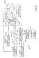
- FIG. 1 is a schematic diagram of a system for determining ocular aberrations.
- FIG. 2 is a graph of desired and achieved ablation depths as a function ofradial position for a myopic eye.
- FIG. 3 is a graph of desired and achieved ablation depths as a function ofradial position for a hyperopic eye.
- FIGS. 4A and4B are graphs of the ablation efficiency function of the presentinvention: FIG. 4A plots 1 - 0.3r2, wherermax = 3.25 mm; FIG. 4B plots 0.95 -0.3r2 -0.25r3 + 0.3r4.
- FIG. 5 is a schematic diagram of a system for delivering an ablative laserbeam to an eye.
- A description of the preferred embodiments of the present invention will nowbe presented with reference to FIGS. 1-5.
- The system for correcting visual defects of an eye includes awavefront analyzer, in a preferred embodiment a system 10 (FIG. 1) similar to thatdescribed in U.S Patent No. 6271915.The apparatus10 includesa laser12 for generating optical radiation used to produce a small-diameter laserbeam14. The laser12 generates a collimated laser light beam (represented bydashed lines for the beam14) of a wavelength and power that is eye-safe. Forophthalmic applications, appropriate wavelengths would include the entire visiblespectrum and the near-infrared spectrum. By way of example, appropriatewavelengths may be in a range of from approximately 400-1000 nms, including 550-,650-, and 850-nm useful wavelengths. While operation in the visible spectrum isgenerally desired, since these are the conditions in which the eye operates, the near-infraredspectrum may offer advantages in certain applications. For example, thepatient's eye may be more relaxed if the patient does not know measurement istaking place. Regardless of the wavelength ofthe optical radiation, power should berestricted in ophthalmic applications to eye-safe levels. For laser radiation, appropriate eye-safe exposure levels can be found in the U.S. Federal PerformanceStandard for Laser Products. If the analysis is to be performed on an optical systemother than the eye, the examination wavelength range logically should incorporatethe intended performance range of the system.
- To select a small-diameter collimated core of laser light beam14, an irisdiaphragm16 is used to block all of laser light beam14 except for the laser beam18of a size desired for use. In terms of the present invention, the laser beam18 willhave a diameter in the range of approximately 0.5-4.5 mm, with 1-3 mm beingtypical, by way of example. A badly aberrated eye uses a smaller-diameter beam,while an eye with only slight aberrations can be evaluated with a larger-diameterbeam. Depending on the output divergence of the laser12, a lens can be positionedin the beam path to optimize collimating of the beam.
- Laser beam18, as herein described by way of example, is a polarized beamthat is passed through a polarization-sensitive beam splitter20 for routing to afocusing optical train22, which operates to focus the laser beam18 through theoptics of the eye120 (e.g., the cornea126, pupil125, and the lens124) to the retina122. It is to be understood that the lens124 may not be present for a patient thathas undergone a cataract procedure. However, this does not affect the presentinvention.
- The optical train22 images the laser beam18 as a small spot of light at ornear the eye'sfovea centralis123, where the eye's vision is most acute. Note thatthe small spot of light could be reflected off another portion of retina122 in order todetermine aberrations related to another aspect of one's vision. For example, if thespot of light were reflected off the area of the retina122 surrounding thefoveacentralis123, aberrations specifically related to one's peripheral vision could then beevaluated. In all cases, the spot of light may be sized to form a near-diffraction-limitedimage on the retina122. Thus the spot of light produced by laser beam18atfovea centralis123 does not exceed approximately 100 µm in diameter and,typically, is on the order of 10 µm.
- The diffuse reflection of the laser beam18 back from the retina122 isrepresented by solid lines247 indicative of radiation that passes back through the eye120. The wavefront24 impinges on and is passed through the optical train22 andon to the polarization-sensitive beam splitter20. The wavefront24 is depolarizedrelative to the laser beam18 due to reflection and refraction as the wavefront24emanates from the retina122. Accordingly, the wavefront24 is turned at thepolarization-sensitive beam splitter20 and directed to a wavefront analyzer26 suchas a Hartmann-Shack (H-S) wavefront analyzer. In general, the wavefront analyzer26 measures the slopes of wavefront24, i.e., the partial derivatives with respect tox andy, at a number of (x,y) transverse coordinates. This partial derivativeinformation is then used to reconstruct or approximate the original wavefront with amathematical expression such as a weighted series of Zemike polynomials.
- The polarization states for the incident laser beam18 and the beam splitter20 minimizes the amount of stray laser radiation reaching the sensor portion of thewavefront analyzer26. In some situations, stray radiation may be sufficiently smallwhen compared to the radiation returning from the desired target (e.g., the retina122) so that the polarization specifications are unnecessary.
- The present invention is able to adapt to a wide range of vision defects andas such achieves a new level of dynamic range in terms of measuring ocularaberrations. Dynamic range enhancement is accomplished with the optical train22and/or a wavefront sensor portion of the wavefront analyzer26. The optical train22includes a first lens220, a flat mirror221, a Porro mirror222, and a second lens224,all of which lie along the path of laser beam18 and the wavefront24. The first lens220 and the second lens224 are identical lenses maintained in fixed positions. ThePorro mirror222 is capable of linear movement, as indicated by arrow223 to changethe optical path length between the lenses220 and224. However, it is to beunderstood that the present invention is not limited to the particular arrangement ofthe flat mirror221 and the Porro mirror222 and that other optical arrangements maybe used without departing from the teachings and benefits of the present invention.
- A "zero position" of the Porro mirror222 is identified by replacing the eye120by a calibration source of collimated light to provide a reference wavefront such asa perfect plane wave110. Such a source could be realized by a laser beamexpanded by a beam telescope to the diameter that will cover the imaging plane of wavefront analyzer26 and adjustment of the Porro mirror222 until the wavefrontanalyzer26 detects the light as being collimated. Note that the changes in opticalpath length brought about by the Porro mirror222 can be calibrated in diopters toprovide an approximate spherical dioptric correction.
- In order to empirically determine a treatment efficiency of a particular beamprofile in effecting a desired change in refraction, data were collected on the ablationof human corneasin vivo with known ablation profiles and known laser beam fluenceprofiles. The precision and lack of subjectivity of the above-discussed wavefrontmeasurement was used to determine the optical results and hence the effectivetreatment efficiency of particular ablation profiles. Any deviations from the expectedchange in aberration content can be attributed to relative differences in ablationeffectiveness across the corneal surface.
- A single generalized ablation effectiveness function was derived from clinicaldata using both myopic and hyperopic nominal ablation profiles. The data werecollected from nominal ablation profiles obtained using an excimer laser narrow-beamscanning spot such as that disclosed in U.S. Patent Nos. 5,849,006 and5,632,742.
- The radially symmetric attenuation function of the present invention wasdetermined by analysis of graphs of intended and achieved ablation depth versusnormalized radial corneal position for myopic (FIG. 2) and hyperopic (FIG. 3) eyes.In its general form the ablation effectiveness function has the polynomial formA +Bρ+Cρ2 +Dρ3 + ... +Xρn, as described above. In a specific embodiment thefunction has the formA +Bρ +Cρ2+ Dρ3 +Eρ4, with exemplary coefficientsA ≅0.95,B ≅ 0,C ≅ -0.3,D = -0.25, andE = 0.3 for an optical zone radius of 3.25 mm.The ablation effectiveness function includes any radial dependence in the actualablation rate, that is, for example, micrometers of tissue removed per pulse.However, it also incorporates any biomechanical effect or intrinsic variation in cornealoptical properties that can influence the optical outcome in a radially dependentmanner.
- The attenuation or efficiency function is then used to modify the treatmentprofile by taking the desired change in corneal depth (the nominal ablation profile) and dividing this by the attenuation function. This yields a new profile that, whenablated, results in the desired change.
- In a particular embodiment the attenuation is achieved by computing theZernike description of the ablation profile and dividing the Zernike polynomial by theattenuation profile that is entered into the laser beam delivery system:
- In a graph of a simple form of this function, 1 - 0.3r2, wherermax = 3.25 mm(FIG. 4A), the radially dependent ablation efficiency varies from a value ofapproximately 1 proximate a central location whereinr ≅ 0 on the corneal surface toa value of approximately 0.7 at a distance from the central location whereinr ≅ 3.25mm.
- A more detailed version of the attenuation function, 0.95 - 0.3r2 - 0.25r3 +0.3r4, which has a more complex shape, is shown in FIG. 4B. The specific functionapplied for a particular treatment laser system may depend on specifics of thatdevice, such as beam energy, etc. Therefore, the coefficients in the attenuationfunction polynomial can be adjusted to optimize results for particular treatmentconditions.
- Preferably the optical correction is further based on refractive indices of mediathrough which the wavefront passes. In a particular embodiment, the converterprovides the path difference using a Zernike reconstruction of the wavefront, and thepath difference is divided by a difference between an index of refraction of cornealmaterial and an index of refraction of air. The optical correction is a prescribedalteration of corneal surface curvature of the eye, and the optical correction achievedby the reshaping of the corneal surface curvature of the eye is based on theprescribed alteration without regard to a resulting topography of the overall surfaceof the cornea.
- An exemplary laser beam delivery system5 (FIG. 5) laser beam delivery andeye tracking system may comprise, for example, that taught in U.S. Pat. No.5,980,513.The laser beam delivery portion of system5includes treatment laser source500, projection optics510, X-Y translation mirror optics520, beam translation controller530, dichroic beamsplitter200, and beamangle adjustment mirror optics300. The laser pulses are distributed as shots overthe area to be ablated or eroded, preferably in a distributed sequence so that thedesired shape of the object or cornea is achieved. Preferably the pulsed laser beamis shifted to direct the shots to a plurality of spatially displaced positions on thecorneal surface to form a plurality of spatially distributed ablation spots. Each ofthese spots may have a predetermined diameter, for example, 2.5 or 1.0 mm, andmay have an intensity distribution, for example, defined by a Gaussian or a generallyflat distribution profile across the spot.
- In operation of the beam delivery portion of system5, laser source500produces laser beam502 incident upon projection optics510. Projection optics510adjusts the diameter and distance to focus of beam502 depending on therequirements of the particular procedure being performed.
- After exiting projection optics510, beam502 impinges on X-Y translationmirror optics520, where beam502 is translated or shifted independently along eachof two orthogonal translation axes as governed by beam translation controller 530.Controller530 is typically a processor programmed with a predetermined set of two-dimensionaltranslations or shifts of beam502 depending on the particularophthalmic procedure being performed. Each of the X and Y axes of translation isindependently controlled by a translating mirror.
- The eye tracking portion of system5 includes eye movement sensor100,dichroic beamsplitter200, and beam angle adjustment mirror optics300. Sensor100 determines the amount of eye movement and uses thatamount to adjust mirrors310 and320 to track along with the eye movement. To do this, sensor100 firsttransmits light energy101-T, which has been selected to transmit through dichroicbeamsplitter200. At the same time, after undergoing beam translation inaccordance with the particular treatment procedure, beam502 impinges on dichroicbeamsplitter200, which has been selected to reflect beam502 (e.g., a 193-nmwavelength laser beam) to beam angle adjustment mirror optics300.
- Light energy101-T is aligned such that it is parallel to beam502 as it impingeson beam angle adjustment mirror optics300. It is to be understood that the term "parallel" as used herein includes the possibility that light energy101-T and beam502 can be coincident or collinear. Both light energy101-T and beam502 areadjusted in correspondence with one another by optics300. Accordingly, lightenergy101-T and beam502 retain their parallel relationship when they are incidenton eye120. Since X-Y translation mirror optics520 shifts the position of beam502in translation independently of optics300, the parallel relationship between beam502 and light energy101-T is maintained throughout the particular ophthalmicprocedure.
- The beam angle adjustment mirror optics consists of independently rotatingmirrors310 and320. Mirror310 is rotatable about axis312, as indicated by arrow314, while mirror320 is rotatable about axis322, as indicated by arrow324. Axes312 and322 are orthogonal to one another. In this way, mirror310 is capable ofsweeping light energy101-T and beam502 in a first plane (e.g., elevation), whilemirror320 is capable of independently sweeping light energy101-T and beam502in a second plane (e.g., azimuth) that is perpendicular to the first plane. Upon exitingbeam angle adjustment mirror optics300, light energy101-T and beam502 impingeon eye120.
- The movement of mirrors310 and320 is typically accomplished with servocontroller/motor drivers316 and326, respectively. In general, drivers316 and326must be able to react quickly when the measured error from eye movement sensor100 is large, and further must provide very high gain from low frequencies (DC) toabout 100 radians per second to virtually eliminate both steady-state and transienterror.
- More specifically, eye movement sensor100 provides a measure of the errorbetween the center of the pupil (or an offset from the center of the pupil that thedoctor selected) and the location where mirror310 is pointed.
- Light energy101-R reflected from eye120 travels back through optics300and beamsplitter200 for detection at sensor100. Sensor100 determines theamount of eye movement based on the changes in reflection energy101-R. Errorcontrol signals indicative of the amount of eye movement are fed back by sensor100to beam angle adjustment mirror optics300. The error control signals govern the movement or realignment of mirrors310 and320 in an effort to drive the error controlsignals to zero. In doing this, light energy101-T and beam502 are moved incorrespondence with eye movement while the actual position of beam502 relativeto the center of the pupil is controlled by X-Y translation mirror optics520.
- In order to take advantage of the properties of beamsplitter200, light energy101-T must be of a different wavelength than that of treatment laser beam502. Thelight energy should preferably lie outside the visible spectrum so as not to interfereor obstruct a surgeon's view of eye120. Further, if the present invention is to beused in ophthalmic surgical procedures, light energy101-T must be "eye safe," asdefined by the American National Standards Institute (ANSI). While a variety of lightwavelengths satisfy the above requirements, by way of example, light energy101-Tmay comprise infrared light energy in the 900-nm wavelength region. Light in thisregion meets the above-noted criteria and is further produced by readily available,economically affordable light sources. One such light source is a high pulse repetitionrate GaAs 905-nm laser operating at 4 kHz, which produces an ANSI-defined eye-safepulse of 10 nJ in a 50-ns pulse. A corneal ablation system using 193-nmablation in a range of fluences of 100-1000 mJ/cm2, which uses a small spot (< 2.5mm) may also be used. One preferred embodiment utilizes a spot < 1.0 mm and400-600 mJ/cm2 peak fluences.
- Thus it can be seen that the present invention provides a systemfor providing a compensating correction function adapted to negate or cancel out theablation efficiency function to permit the actual desired shape of the corneal removalvolume to be obtained, effecting an ideal optical result.
- In the foregoing description, certain terms have been used for brevity, clarity,and understanding, but no unnecessary limitations are to be implied therefrombeyond the requirements of the prior art, because such words are used fordescription purposes herein and are intended to be broadly construed. Moreover,the embodiments of the apparatus illustrated and described herein are by way ofexample, and the scope of the invention is not limited to the exact details ofconstruction.
- Having now described the invention, the construction, the operation and useof preferred embodiment thereof, and the advantageous new and useful resultsobtained thereby, the new and useful constructions, and reasonable mechanicalequivalents thereof obvious to those skilled in the art, are set forth in the appendedclaims.
Claims (4)
- An optical correction system (10) for correcting visual defects of an eye (120),the optical correction system comprising:characterized byan energy source (12) for generating a beam (18) of optical radiation;focusing optics (22) disposed in the path of the beam for directing thebeam through the eye, wherein the beam is reflected back from the retina(122) of the eye as a wavefront (24) of radiation emanating from the eye;a wavefront analyser (26) responsive to the wavefront emanating fromthe eye for determining an optical path difference between a reference wave(110) and the wavefront;a converter for calculating an optical correction based on the pathdifference; anda treatment laser system (500) for producing a laser beam (502) havingpower sufficient for ablating corneal material (126), whereby the opticalcorrection is achieved by the removal of a selected amount of corneal materialto create a desired corneal shape change;
a converter for calculating an optical correction based on the pathdifference and on a radially dependent ablation effectiveness function using acompensating polynomial of the formA +Bρ +Cρ2 +Dρ3 + ... +Xρn, where ρis a normalized radius measured from a central portion of the cornea (126),reaching a value of 1 at an outer edge of the optical correction zone;wherein the radially dependent ablation efficiencyvaries from a value of approximately 1.0 proximate a central location whereinr ≈ 0 on the corneal surface to a value of approximately 0.7 at the outer edgeof the optical correction zone, for an optical radius of approximately 3.25 mm; and
wherein the converter calculates the path difference using a Zernickereconstruction of the wavefront, and wherein the path difference is divided bya difference between an index of refraction of the corneal material and anindex of refraction of air. - The system of claim 1, wherein the ablation effectiveness function is used tomodify a treatment profile by taking the desired change in corneal depth, ornominal ablation profile, computing the Zemicke description of the ablation profile and dividing the Zemicke polynomial by an attenuation profile that isentered into the said treatment laser system, represented by:
- The system of claim 1, wherein the polynomial has the formA +Bρ +Cρ2 +Dρ3 +Eρ4, with coefficientsA ≈ 0.95,B ≈ 0,C ≈ -0.3,D ≈ -0.25 andE ≈0.3, for an optical radius of approximately 3.25 mm.
- The system of any one of claims 1 to 5, further comprising an eye tracker (25)for monitoring motion of the eye and for adjusting positions of the laser beamresponsive to the motion.
Applications Claiming Priority (3)
| Application Number | Priority Date | Filing Date | Title |
|---|---|---|---|
| US19118700P | 2000-03-22 | 2000-03-22 | |
| US191187P | 2000-03-22 | ||
| PCT/US2001/040352WO2001087201A1 (en) | 2000-03-22 | 2001-03-22 | Optimization of ablation correction of an optical system and associated methods |
Publications (2)
| Publication Number | Publication Date |
|---|---|
| EP1235538A1 EP1235538A1 (en) | 2002-09-04 |
| EP1235538B1true EP1235538B1 (en) | 2004-06-02 |
Family
ID=22704467
Family Applications (1)
| Application Number | Title | Priority Date | Filing Date |
|---|---|---|---|
| EP01923348AExpired - LifetimeEP1235538B1 (en) | 2000-03-22 | 2001-03-22 | Optimization of ablation correction of an optical system |
Country Status (13)
| Country | Link |
|---|---|
| US (1) | US6569154B2 (en) |
| EP (1) | EP1235538B1 (en) |
| JP (1) | JP2003533277A (en) |
| AR (1) | AR032312A1 (en) |
| AT (1) | ATE268150T1 (en) |
| AU (1) | AU770888B2 (en) |
| BR (1) | BR0105551A (en) |
| CA (1) | CA2375163A1 (en) |
| DE (1) | DE60103609T2 (en) |
| DK (1) | DK1235538T3 (en) |
| ES (1) | ES2217137T3 (en) |
| MX (1) | MXPA01010535A (en) |
| WO (1) | WO2001087201A1 (en) |
Families Citing this family (33)
| Publication number | Priority date | Publication date | Assignee | Title |
|---|---|---|---|---|
| DE19938203A1 (en) | 1999-08-11 | 2001-02-15 | Aesculap Meditec Gmbh | Method and device for correcting visual defects in the human eye |
| US6923802B2 (en)* | 2000-03-13 | 2005-08-02 | Memphis Eye & Cataract Assoc. | System for generating ablation profiles for laser refractive eye surgery |
| US7044944B2 (en)* | 2000-03-22 | 2006-05-16 | Alcon Refractivehorizons, Inc. | Optimization of ablation correction of an optical system and associated methods |
| US7431455B2 (en)* | 2005-03-22 | 2008-10-07 | Amo Manufacturing Usa, Llc | Pupilometer for pupil center drift and pupil size measurements at differing viewing distances |
| IL137635A0 (en)* | 2000-08-01 | 2001-10-31 | Visionix Ltd | Apparatus for interactive optometry |
| IL143503A0 (en)* | 2001-05-31 | 2002-04-21 | Visionix Ltd | Aberration correction spectacle lens |
| US6609794B2 (en) | 2001-06-05 | 2003-08-26 | Adaptive Optics Associates, Inc. | Method of treating the human eye with a wavefront sensor-based ophthalmic instrument |
| US6669341B2 (en) | 2001-08-31 | 2003-12-30 | Metrologic Instruments, Inc. | Ophthalmic instrument having wavefront sensor with multiple imaging devices that simultaneously capture multiple images of an array of spots produced by a lenslet array |
| US6554429B1 (en) | 2001-10-15 | 2003-04-29 | Alcon, Inc. | Method for determining accommodation |
| US6666857B2 (en)* | 2002-01-29 | 2003-12-23 | Robert F. Smith | Integrated wavefront-directed topography-controlled photoablation |
| US7130835B2 (en)* | 2002-03-28 | 2006-10-31 | Bausch & Lomb Incorporated | System and method for predictive ophthalmic correction |
| US7083609B2 (en)* | 2002-06-13 | 2006-08-01 | Visx, Incorporated | Corneal topography-based target warping |
| US6939342B2 (en)* | 2002-12-12 | 2005-09-06 | Bausch And Lomb Incorporated | System and method for evaluating a secondary LASIK treatment |
| US7338164B2 (en)* | 2003-07-31 | 2008-03-04 | Visx, Incorporated | Systems and methods for eye aberration and image sensor orientation |
| US7226443B1 (en)* | 2003-11-07 | 2007-06-05 | Alcon Refractivehorizons, Inc. | Optimization of ablation correction of an optical system and associated methods |
| JP4609838B2 (en)* | 2004-08-10 | 2011-01-12 | 株式会社ニデック | Cornea surgery device |
| DE102005006897A1 (en)* | 2005-02-15 | 2006-08-24 | Carl Zeiss Meditec Ag | Ablation program establishing method for correcting ametropia of human eye, involves establishing ablation program based on water concentration of surface to be ablated and pre-compensated set-point ablation profile |
| EP1848389B1 (en) | 2005-02-15 | 2011-07-20 | Carl Zeiss Meditec AG | Method for the establishment of an ablation program and means for carrying out said methods |
| WO2007002487A2 (en) | 2005-06-24 | 2007-01-04 | Boston Foundation For Sight | Scleral contact lens with grooves and method of making lens |
| TWI262325B (en)* | 2005-11-16 | 2006-09-21 | Ind Tech Res Inst | Eye aberration measurement and calibrating equipment and its method |
| CA2687100C (en) | 2007-05-11 | 2016-04-12 | Charles E. Campbell | Combined wavefront and topography systems and methods |
| WO2009003107A1 (en)* | 2007-06-26 | 2008-12-31 | Bausch & Lomb Incorporated | Method for modifying the refractive index of ocular tissues |
| US7988290B2 (en)* | 2007-06-27 | 2011-08-02 | AMO Wavefront Sciences LLC. | Systems and methods for measuring the shape and location of an object |
| US7976163B2 (en) | 2007-06-27 | 2011-07-12 | Amo Wavefront Sciences Llc | System and method for measuring corneal topography |
| US8740381B2 (en)* | 2007-06-27 | 2014-06-03 | Bausch & Lomb Incorporated | Method and apparatus for extrapolating diagnostic data |
| US20090299345A1 (en)* | 2008-05-27 | 2009-12-03 | Bille Josef F | System and method for reshaping a cornea using a combination of liob and structural change procedures |
| US7695135B1 (en) | 2008-11-11 | 2010-04-13 | Boston Foundation For Sight | Scleral lens with scalloped channels or circumferential fenestrated channels |
| US7988293B2 (en)* | 2008-11-14 | 2011-08-02 | AMO Wavefront Sciences LLC. | Method of qualifying light spots for optical measurements and measurement instrument employing method of qualifying light spots |
| US8622546B2 (en) | 2011-06-08 | 2014-01-07 | Amo Wavefront Sciences, Llc | Method of locating valid light spots for optical measurement and optical measurement instrument employing method of locating valid light spots |
| US9265458B2 (en) | 2012-12-04 | 2016-02-23 | Sync-Think, Inc. | Application of smooth pursuit cognitive testing paradigms to clinical drug development |
| US9380976B2 (en) | 2013-03-11 | 2016-07-05 | Sync-Think, Inc. | Optical neuroinformatics |
| CA2904894C (en)* | 2013-03-13 | 2021-07-27 | Optimedica Corporation | Free floating support for laser eye surgery system |
| US10751217B2 (en) | 2013-03-13 | 2020-08-25 | Amo Development, Llc | Free floating patient interface for laser surgery system |
Family Cites Families (23)
| Publication number | Priority date | Publication date | Assignee | Title |
|---|---|---|---|---|
| US4420228A (en)* | 1980-06-12 | 1983-12-13 | Humphrey Instruments, Inc. | Method and apparatus for analysis of corneal shape |
| FR2566140B1 (en) | 1984-06-15 | 1986-09-05 | Onera (Off Nat Aerospatiale) | DEVICE FOR ANALYZING AND CORRECTING REAL-TIME WAVE SURFACES WITH A POLARIZED INTERFEROMETER |
| US4669466A (en) | 1985-01-16 | 1987-06-02 | Lri L.P. | Method and apparatus for analysis and correction of abnormal refractive errors of the eye |
| US4750818A (en) | 1985-12-16 | 1988-06-14 | Cochran Gregory M | Phase conjugation method |
| US5106183A (en) | 1987-11-25 | 1992-04-21 | Taunton Technologies, Inc. | Topography measuring apparatus |
| US5221834A (en) | 1991-06-28 | 1993-06-22 | Eastman Kodak Company | Method for providing feedback correction for an imaging device |
| US5339121A (en) | 1991-11-01 | 1994-08-16 | Visx, Incorported | Rectilinear photokeratoscope |
| US5233174A (en) | 1992-03-11 | 1993-08-03 | Hughes Danbury Optical Systems, Inc. | Wavefront sensor having a lenslet array as a null corrector |
| US5841511A (en) | 1992-06-02 | 1998-11-24 | Eyesys Technologies, Inc. | Method of corneal analysis using a checkered placido apparatus |
| US5452031A (en) | 1993-05-05 | 1995-09-19 | Boston Eye Technology, Inc. | Contact lens and a method for manufacturing contact lens |
| US5849006A (en) | 1994-04-25 | 1998-12-15 | Autonomous Technologies Corporation | Laser sculpting method and system |
| US5632742A (en)* | 1994-04-25 | 1997-05-27 | Autonomous Technologies Corp. | Eye movement sensing method and system |
| US5493391A (en) | 1994-07-11 | 1996-02-20 | Sandia Corporation | One dimensional wavefront distortion sensor comprising a lens array system |
| US5684545A (en) | 1995-07-07 | 1997-11-04 | New Mexico State University Technology Transfer Corp. | Adaptive optics wave measurement and correction system |
| US5822035A (en) | 1996-08-30 | 1998-10-13 | Heidelberg Engineering Optische Messysteme Gmbh | Ellipsometer |
| US6271914B1 (en)* | 1996-11-25 | 2001-08-07 | Autonomous Technologies Corporation | Objective measurement and correction of optical systems using wavefront analysis |
| US5777719A (en) | 1996-12-23 | 1998-07-07 | University Of Rochester | Method and apparatus for improving vision and the resolution of retinal images |
| US6302876B1 (en)* | 1997-05-27 | 2001-10-16 | Visx Corporation | Systems and methods for imaging corneal profiles |
| DK1032809T3 (en)* | 1997-11-21 | 2007-05-14 | Alcon Inc | Objective measurement and correction of optical systems using wavefront analysis |
| ES2277430T3 (en)* | 1998-03-04 | 2007-07-01 | Visx Incorporated | LASER PRESBORAGE TREATMENT SYSTEM. |
| US6322216B1 (en)* | 1999-10-07 | 2001-11-27 | Visx, Inc | Two camera off-axis eye tracker for laser eye surgery |
| US6394999B1 (en)* | 2000-03-13 | 2002-05-28 | Memphis Eye & Cataract Associates Ambulatory Surgery Center | Laser eye surgery system using wavefront sensor analysis to control digital micromirror device (DMD) mirror patterns |
| US6460997B1 (en)* | 2000-05-08 | 2002-10-08 | Alcon Universal Ltd. | Apparatus and method for objective measurements of optical systems using wavefront analysis |
- 2001
- 2001-03-22EPEP01923348Apatent/EP1235538B1/ennot_activeExpired - Lifetime
- 2001-03-22JPJP2001583672Apatent/JP2003533277A/enactivePending
- 2001-03-22WOPCT/US2001/040352patent/WO2001087201A1/enactiveIP Right Grant
- 2001-03-22CACA002375163Apatent/CA2375163A1/ennot_activeAbandoned
- 2001-03-22ATAT01923348Tpatent/ATE268150T1/enactive
- 2001-03-22AUAU50048/01Apatent/AU770888B2/ennot_activeExpired
- 2001-03-22DKDK01923348Tpatent/DK1235538T3/enactive
- 2001-03-22BRBR0105551-8Apatent/BR0105551A/ennot_activeIP Right Cessation
- 2001-03-22ESES01923348Tpatent/ES2217137T3/ennot_activeExpired - Lifetime
- 2001-03-22DEDE60103609Tpatent/DE60103609T2/ennot_activeExpired - Lifetime
- 2001-03-22ARARP010101349Apatent/AR032312A1/ennot_activeApplication Discontinuation
- 2001-03-22USUS09/814,398patent/US6569154B2/ennot_activeExpired - Lifetime
- 2001-03-22MXMXPA01010535Apatent/MXPA01010535A/enactiveIP Right Grant
Non-Patent Citations (1)
| Title |
|---|
| MACRAE S.: "Guest Editorial", JOURNAL OF CATARACT AND REFRACTIVE SURGERY, vol. 26, no. 2, February 2000 (2000-02-01)* |
Also Published As
| Publication number | Publication date |
|---|---|
| BR0105551A (en) | 2002-03-05 |
| WO2001087201A1 (en) | 2001-11-22 |
| DK1235538T3 (en) | 2004-10-04 |
| ES2217137T3 (en) | 2004-11-01 |
| JP2003533277A (en) | 2003-11-11 |
| CA2375163A1 (en) | 2001-11-22 |
| DE60103609D1 (en) | 2004-07-08 |
| US20020007176A1 (en) | 2002-01-17 |
| US6569154B2 (en) | 2003-05-27 |
| ATE268150T1 (en) | 2004-06-15 |
| EP1235538A1 (en) | 2002-09-04 |
| MXPA01010535A (en) | 2002-11-04 |
| DE60103609T2 (en) | 2005-07-28 |
| AU5004801A (en) | 2001-11-26 |
| AR032312A1 (en) | 2003-11-05 |
| AU770888B2 (en) | 2004-03-04 |
Similar Documents
| Publication | Publication Date | Title |
|---|---|---|
| EP1235538B1 (en) | Optimization of ablation correction of an optical system | |
| US7044944B2 (en) | Optimization of ablation correction of an optical system and associated methods | |
| JP2003533277A5 (en) | ||
| US6887231B2 (en) | Control program for a device for photorefractive corneal surgery of the eye | |
| JP3499874B2 (en) | Eye movement detection system | |
| CA2385909C (en) | Customized corneal profiling | |
| US6419671B1 (en) | Optical feedback system for vision correction | |
| EP1032809B1 (en) | Objective measurement and correction of optical systems using wavefront analysis | |
| JP3771497B2 (en) | Eye tracker control system and control method | |
| JP2005514998A5 (en) | ||
| US20050099600A1 (en) | Apparatus and method for objective measurement and correction of optical systems using wavefront analysis | |
| JP2008149164A (en) | Apparatus and method for objective measurement and correction of optical system using wavefront analysis | |
| US20230201036A1 (en) | Uv-laser-based system for correcting vision disorders | |
| US20230181365A1 (en) | Uv-laser-based system for correcting impaired vision, and method for centering same | |
| Alekseev et al. | Expanding of Excimer Laser Photoablation’s Functionality in Ophthalmology | |
| US20230201035A1 (en) | System for laser-based ametropia correction, and method for the alignment thereof | |
| PT1465539E (en) | Optimization of ablation correction of an optical system | |
| MXPA06009378A (en) | Methods and systems for differentiating left and right eye images |
Legal Events
| Date | Code | Title | Description |
|---|---|---|---|
| PUAI | Public reference made under article 153(3) epc to a published international application that has entered the european phase | Free format text:ORIGINAL CODE: 0009012 | |
| 17P | Request for examination filed | Effective date:20011026 | |
| AK | Designated contracting states | Kind code of ref document:A1 Designated state(s):AT BE CH CY DE DK ES FI FR GB GR IE IT LI LU MC NL PT SE TR | |
| AX | Request for extension of the european patent | Free format text:AL;LT;LV;MK;RO;SI | |
| 17Q | First examination report despatched | Effective date:20020828 | |
| RAP1 | Party data changed (applicant data changed or rights of an application transferred) | Owner name:ALCON, INC. | |
| GRAP | Despatch of communication of intention to grant a patent | Free format text:ORIGINAL CODE: EPIDOSNIGR1 | |
| RTI1 | Title (correction) | Free format text:OPTIMIZATION OF ABLATION CORRECTION OF AN OPTICAL SYSTEM | |
| GRAS | Grant fee paid | Free format text:ORIGINAL CODE: EPIDOSNIGR3 | |
| GRAA | (expected) grant | Free format text:ORIGINAL CODE: 0009210 | |
| AK | Designated contracting states | Kind code of ref document:B1 Designated state(s):AT BE CH CY DE DK ES FI FR GB GR IE IT LI LU MC NL PT SE TR | |
| PG25 | Lapsed in a contracting state [announced via postgrant information from national office to epo] | Ref country code:TR Free format text:LAPSE BECAUSE OF FAILURE TO SUBMIT A TRANSLATION OF THE DESCRIPTION OR TO PAY THE FEE WITHIN THE PRESCRIBED TIME-LIMIT Effective date:20040602 | |
| REG | Reference to a national code | Ref country code:GB Ref legal event code:FG4D | |
| REG | Reference to a national code | Ref country code:CH Ref legal event code:EP | |
| REF | Corresponds to: | Ref document number:60103609 Country of ref document:DE Date of ref document:20040708 Kind code of ref document:P | |
| REG | Reference to a national code | Ref country code:IE Ref legal event code:FG4D | |
| REG | Reference to a national code | Ref country code:CH Ref legal event code:NV Representative=s name:CRONIN INTELLECTUAL PROPERTY | |
| PG25 | Lapsed in a contracting state [announced via postgrant information from national office to epo] | Ref country code:GR Free format text:LAPSE BECAUSE OF FAILURE TO SUBMIT A TRANSLATION OF THE DESCRIPTION OR TO PAY THE FEE WITHIN THE PRESCRIBED TIME-LIMIT Effective date:20040902 | |
| REG | Reference to a national code | Ref country code:DK Ref legal event code:T3 | |
| REG | Reference to a national code | Ref country code:SE Ref legal event code:TRGR | |
| REG | Reference to a national code | Ref country code:ES Ref legal event code:FG2A Ref document number:2217137 Country of ref document:ES Kind code of ref document:T3 | |
| LTIE | Lt: invalidation of european patent or patent extension | Effective date:20040602 | |
| ET | Fr: translation filed | ||
| PLAQ | Examination of admissibility of opposition: information related to despatch of communication + time limit deleted | Free format text:ORIGINAL CODE: EPIDOSDOPE2 | |
| PLBQ | Unpublished change to opponent data | Free format text:ORIGINAL CODE: EPIDOS OPPO | |
| PLBI | Opposition filed | Free format text:ORIGINAL CODE: 0009260 | |
| PG25 | Lapsed in a contracting state [announced via postgrant information from national office to epo] | Ref country code:CY Free format text:LAPSE BECAUSE OF FAILURE TO SUBMIT A TRANSLATION OF THE DESCRIPTION OR TO PAY THE FEE WITHIN THE PRESCRIBED TIME-LIMIT Effective date:20050322 | |
| PLAB | Opposition data, opponent's data or that of the opponent's representative modified | Free format text:ORIGINAL CODE: 0009299OPPO | |
| PLAQ | Examination of admissibility of opposition: information related to despatch of communication + time limit deleted | Free format text:ORIGINAL CODE: EPIDOSDOPE2 | |
| PLAR | Examination of admissibility of opposition: information related to receipt of reply deleted | Free format text:ORIGINAL CODE: EPIDOSDOPE4 | |
| PLAX | Notice of opposition and request to file observation + time limit sent | Free format text:ORIGINAL CODE: EPIDOSNOBS2 | |
| PLBQ | Unpublished change to opponent data | Free format text:ORIGINAL CODE: EPIDOS OPPO | |
| 26 | Opposition filed | Opponent name:WAVELIGHT LASER TECHNOLOGIE AG Effective date:20050302 | |
| R26 | Opposition filed (corrected) | Opponent name:WAVELIGHT LASER TECHNOLOGIE AG Effective date:20050302 | |
| NLR1 | Nl: opposition has been filed with the epo | Opponent name:WAVELIGHT LASER TECHNOLOGIE AG | |
| NLR1 | Nl: opposition has been filed with the epo | Opponent name:WAVELIGHT LASER TECHNOLOGIE AG | |
| PLBB | Reply of patent proprietor to notice(s) of opposition received | Free format text:ORIGINAL CODE: EPIDOSNOBS3 | |
| RAP2 | Party data changed (patent owner data changed or rights of a patent transferred) | Owner name:ALCON, INC. | |
| NLT2 | Nl: modifications (of names), taken from the european patent patent bulletin | Owner name:ALCON, INC. Effective date:20060111 | |
| REG | Reference to a national code | Ref country code:CH Ref legal event code:PCAR Free format text:CRONIN INTELLECTUAL PROPERTY;CHEMIN DE PRECOSSY 31;1260 NYON (CH) | |
| PLCK | Communication despatched that opposition was rejected | Free format text:ORIGINAL CODE: EPIDOSNREJ1 | |
| PLBN | Opposition rejected | Free format text:ORIGINAL CODE: 0009273 | |
| STAA | Information on the status of an ep patent application or granted ep patent | Free format text:STATUS: OPPOSITION REJECTED | |
| 27O | Opposition rejected | Effective date:20070424 | |
| NLR2 | Nl: decision of opposition | Effective date:20070424 | |
| PG25 | Lapsed in a contracting state [announced via postgrant information from national office to epo] | Ref country code:PT Free format text:LAPSE BECAUSE OF NON-PAYMENT OF DUE FEES Effective date:20041102 | |
| PGFP | Annual fee paid to national office [announced via postgrant information from national office to epo] | Ref country code:IE Payment date:20110325 Year of fee payment:11 Ref country code:MC Payment date:20110304 Year of fee payment:11 | |
| PGFP | Annual fee paid to national office [announced via postgrant information from national office to epo] | Ref country code:FI Payment date:20110329 Year of fee payment:11 Ref country code:AT Payment date:20110303 Year of fee payment:11 Ref country code:LU Payment date:20110405 Year of fee payment:11 Ref country code:SE Payment date:20110329 Year of fee payment:11 | |
| PGFP | Annual fee paid to national office [announced via postgrant information from national office to epo] | Ref country code:BE Payment date:20120330 Year of fee payment:12 Ref country code:DK Payment date:20120326 Year of fee payment:12 | |
| REG | Reference to a national code | Ref country code:SE Ref legal event code:EUG | |
| PG25 | Lapsed in a contracting state [announced via postgrant information from national office to epo] | Ref country code:FI Free format text:LAPSE BECAUSE OF NON-PAYMENT OF DUE FEES Effective date:20120322 Ref country code:MC Free format text:LAPSE BECAUSE OF NON-PAYMENT OF DUE FEES Effective date:20120331 Ref country code:SE Free format text:LAPSE BECAUSE OF NON-PAYMENT OF DUE FEES Effective date:20120323 | |
| REG | Reference to a national code | Ref country code:AT Ref legal event code:MM01 Ref document number:268150 Country of ref document:AT Kind code of ref document:T Effective date:20120322 | |
| REG | Reference to a national code | Ref country code:IE Ref legal event code:MM4A | |
| PG25 | Lapsed in a contracting state [announced via postgrant information from national office to epo] | Ref country code:AT Free format text:LAPSE BECAUSE OF NON-PAYMENT OF DUE FEES Effective date:20120322 Ref country code:IE Free format text:LAPSE BECAUSE OF NON-PAYMENT OF DUE FEES Effective date:20120322 | |
| BERE | Be: lapsed | Owner name:*ALCON INC. Effective date:20130331 | |
| REG | Reference to a national code | Ref country code:DK Effective date:20130331 Ref legal event code:EBP | |
| PG25 | Lapsed in a contracting state [announced via postgrant information from national office to epo] | Ref country code:BE Free format text:LAPSE BECAUSE OF NON-PAYMENT OF DUE FEES Effective date:20130331 | |
| PG25 | Lapsed in a contracting state [announced via postgrant information from national office to epo] | Ref country code:DK Free format text:LAPSE BECAUSE OF NON-PAYMENT OF DUE FEES Effective date:20130331 | |
| PG25 | Lapsed in a contracting state [announced via postgrant information from national office to epo] | Ref country code:LU Free format text:LAPSE BECAUSE OF NON-PAYMENT OF DUE FEES Effective date:20120322 | |
| REG | Reference to a national code | Ref country code:FR Ref legal event code:PLFP Year of fee payment:16 | |
| REG | Reference to a national code | Ref country code:FR Ref legal event code:PLFP Year of fee payment:17 | |
| REG | Reference to a national code | Ref country code:FR Ref legal event code:PLFP Year of fee payment:18 | |
| REG | Reference to a national code | Ref country code:CH Ref legal event code:PCAR Free format text:NEW ADDRESS: CHEMIN DE LA VUARPILLIERE 29, 1260 NYON (CH) | |
| PGFP | Annual fee paid to national office [announced via postgrant information from national office to epo] | Ref country code:NL Payment date:20190313 Year of fee payment:19 | |
| REG | Reference to a national code | Ref country code:NL Ref legal event code:PD Owner name:ALCON INC.; CH Free format text:DETAILS ASSIGNMENT: CHANGE OF OWNER(S), MERGE; FORMER OWNER NAME: NOVARTIS AG Effective date:20191031 | |
| REG | Reference to a national code | Ref country code:CH Ref legal event code:PUE Owner name:ALCON INC., CH Free format text:FORMER OWNER: ALCON, INC., CH | |
| REG | Reference to a national code | Ref country code:GB Ref legal event code:732E Free format text:REGISTERED BETWEEN 20200109 AND 20200115 | |
| REG | Reference to a national code | Ref country code:GB Ref legal event code:732E Free format text:REGISTERED BETWEEN 20200116 AND 20200122 | |
| REG | Reference to a national code | Ref country code:DE Ref legal event code:R082 Ref document number:60103609 Country of ref document:DE Representative=s name:BOEHMERT & BOEHMERT ANWALTSPARTNERSCHAFT MBB -, DE Ref country code:DE Ref legal event code:R081 Ref document number:60103609 Country of ref document:DE Owner name:ALCON INC., CH Free format text:FORMER OWNER: ALCON INC., HUENENBERG, CH | |
| PGFP | Annual fee paid to national office [announced via postgrant information from national office to epo] | Ref country code:GB Payment date:20200311 Year of fee payment:20 Ref country code:IT Payment date:20200226 Year of fee payment:20 Ref country code:DE Payment date:20200310 Year of fee payment:20 | |
| REG | Reference to a national code | Ref country code:ES Ref legal event code:PC2A Owner name:ALCON INC. Effective date:20200430 | |
| PGFP | Annual fee paid to national office [announced via postgrant information from national office to epo] | Ref country code:CH Payment date:20200313 Year of fee payment:20 | |
| PGFP | Annual fee paid to national office [announced via postgrant information from national office to epo] | Ref country code:FR Payment date:20200227 Year of fee payment:20 | |
| PGFP | Annual fee paid to national office [announced via postgrant information from national office to epo] | Ref country code:ES Payment date:20200401 Year of fee payment:20 | |
| REG | Reference to a national code | Ref country code:NL Ref legal event code:MM Effective date:20200401 | |
| PG25 | Lapsed in a contracting state [announced via postgrant information from national office to epo] | Ref country code:NL Free format text:LAPSE BECAUSE OF NON-PAYMENT OF DUE FEES Effective date:20200401 | |
| REG | Reference to a national code | Ref country code:DE Ref legal event code:R071 Ref document number:60103609 Country of ref document:DE | |
| REG | Reference to a national code | Ref country code:CH Ref legal event code:PL | |
| REG | Reference to a national code | Ref country code:GB Ref legal event code:PE20 Expiry date:20210321 | |
| PG25 | Lapsed in a contracting state [announced via postgrant information from national office to epo] | Ref country code:GB Free format text:LAPSE BECAUSE OF EXPIRATION OF PROTECTION Effective date:20210321 | |
| PG25 | Lapsed in a contracting state [announced via postgrant information from national office to epo] | Ref country code:ES Free format text:LAPSE BECAUSE OF EXPIRATION OF PROTECTION Effective date:20210323 |