EP1235131A2 - Room temperature control - Google Patents
Room temperature controlDownload PDFInfo
- Publication number
- EP1235131A2 EP1235131A2EP01130807AEP01130807AEP1235131A2EP 1235131 A2EP1235131 A2EP 1235131A2EP 01130807 AEP01130807 AEP 01130807AEP 01130807 AEP01130807 AEP 01130807AEP 1235131 A2EP1235131 A2EP 1235131A2
- Authority
- EP
- European Patent Office
- Prior art keywords
- valve
- room temperature
- operating characteristic
- temperature
- temperature control
- Prior art date
- Legal status (The legal status is an assumption and is not a legal conclusion. Google has not performed a legal analysis and makes no representation as to the accuracy of the status listed.)
- Granted
Links
- 238000010438heat treatmentMethods0.000claimsabstractdescription44
- 238000005259measurementMethods0.000claimsabstractdescription5
- 230000000694effectsEffects0.000description5
- 238000000034methodMethods0.000description4
- 230000005855radiationEffects0.000description3
- 238000012937correctionMethods0.000description2
- 238000010586diagramMethods0.000description2
- 238000009434installationMethods0.000description2
- 239000000523sampleSubstances0.000description2
- XLYOFNOQVPJJNP-UHFFFAOYSA-NwaterSubstancesOXLYOFNOQVPJJNP-UHFFFAOYSA-N0.000description2
- 108010014173Factor XProteins0.000description1
- 230000006978adaptationEffects0.000description1
- 230000032683agingEffects0.000description1
- 238000009529body temperature measurementMethods0.000description1
- 230000003247decreasing effectEffects0.000description1
- 230000001419dependent effectEffects0.000description1
- 238000013461designMethods0.000description1
- 238000001914filtrationMethods0.000description1
- 238000009499grossingMethods0.000description1
- 238000011835investigationMethods0.000description1
- 238000005457optimizationMethods0.000description1
- 238000007781pre-processingMethods0.000description1
- 238000012546transferMethods0.000description1
Images
Classifications
- G—PHYSICS
- G05—CONTROLLING; REGULATING
- G05D—SYSTEMS FOR CONTROLLING OR REGULATING NON-ELECTRIC VARIABLES
- G05D23/00—Control of temperature
- G05D23/19—Control of temperature characterised by the use of electric means
- G05D23/1927—Control of temperature characterised by the use of electric means using a plurality of sensors
- G05D23/193—Control of temperature characterised by the use of electric means using a plurality of sensors sensing the temperaure in different places in thermal relationship with one or more spaces
- G05D23/1931—Control of temperature characterised by the use of electric means using a plurality of sensors sensing the temperaure in different places in thermal relationship with one or more spaces to control the temperature of one space
Definitions
- the inventionrelates to a room temperature control with a first temperature sensor for measuring the room air temperature, a second temperature sensor for measuring the flow temperature of a heating medium and a controller for actuation a valve for the heating medium flow.
- heating systemsare with facilities for room temperature control. Usually so-called thermostatic valves are used for this. These are mechanical controls, which measure the room temperature and depending on the difference to Convert setpoint to a stroke position. This technique has proven itself and will often used. However, the regulation of the room temperature is not optimal. The following system-related problems occur:
- valve characteristici.e. the mass flow plotted over the stroke
- one optimally linear valveis a straight line.
- the valve characteristic curvedeforms depending on the valve authority but to a so-called operating characteristic.
- With constant controller parameterscan therefore no constant control quality over the entire Stroke range of the valve can be achieved.
- the controller parameters for large valve authorities and operation of the controller on a valve with a small one In the area of small stroke positionsthe valve authority becomes vibrations tend.
- the control behavior when interpreting the Controller parameters for small valve authorities and operation on one valve with large valve authority or in the area of large stroke positionsbecome very sluggish.
- the room temperature controlleralso detects the influence of the heating medium temperature a higher temperature than the actual temperature in the middle of the room Temperature.
- the heating medium temperature influenceis determined according to DIN EN 215 and is around 0.5K / 30 K with today's controllers, i.e. at a change in the flow temperature by 30 K changes at the same room temperature the temperature recorded by the controller by 0.5 K.
- This measurement erroressentially depends on the operational temperature of the flow and the concrete spatial arrangement. Due to the operational dependency is the measurement error not constant and becomes more or less depending on the current state fluctuating room temperatures.
- DE 32 13 845 A1describes a method for determining the heat emission of radiators or underfloor heating and to regulate the heat emission known with flow, return and room air temperature sensors, where only the measured room air temperature is included in the control.
- EP 0 065 201 B1also contains a method for measuring the heat energy output described by space heaters with three sensors.
- a method for determining the relative described in DE 32 43 198 A1 Heat consumptionis used in addition to the recorded flow and return temperature the stroke position of the valve as a measure of the flow rate of the Heating medium.
- the use of the stroke position as a measure of the flowhas however, the disadvantage that the valve authority is not taken into account which significantly influences the relationship between stroke position and flow.
- the valve authorityis not taken into account which significantly influences the relationship between stroke position and flow.
- the heating systemassumed, which is often not the case in practice. Likewise done no use of the additional signals for the purpose of regulation.
- DE 297 10 248 U1describes a device for recording heat consumption described, in addition to flow, return and room air temperature sensor yet another pressure difference sensor measuring the pressure difference around the valve May contain, but this leads to a further increase in the price of the device. to An additional room air temperature sensor is provided to control the heating output.
- the object of the present inventionis to propose a room temperature control, in which the control quality continues in a simple and inexpensive manner is improved.
- This taskis carried out in a room temperature control of the aforementioned Art according to the invention by a third temperature sensor for measuring the Return temperature of the heating medium solved, whereby from the measured values the Temperature sensor for the indoor air, the flow and the return temperature the operating characteristic of the valve is determined and the control parameters the room temperature control depending on the operating point of the Valve can be adapted to the operating characteristic. From the operating characteristic of the valve, the heating medium flow can be precise for a certain stroke position be read. Therefore it is for the regulation with knowledge of the operating characteristic possible, the control parameters for the necessary stroke change depending on the working point adapt exactly to the desired change in the heating medium flow and thus to avoid overriding the regulation. This will the actual room temperature is directly adapted to the target room temperature and the control quality increased significantly.
- the operating characteristic curveis determined by determining the mass flow determined by the valve with the respective stroke position of the valve, by the mass flow from the quotient of the current heat output and the standard heat output of a radiator or underfloor heating is determined.
- the current heat outputcan easily be from one mean temperature difference between flow, return and indoor air temperature be determined, both an arithmetic averaged temperature difference as well as a logarithmically averaged temperature difference can be.
- an arithmetically averaged temperature differenceshould be used for large temperature differences between the flow and the Return temperature another correction factor can be applied.
- the standard heat outputresults from the standard values of the heating system that are used during commissioning of the regulation.
- the operating characteristic curveis preferably renewed at regular time intervals determined to detect changes in the hydraulic heating system or aging of the valve. As a rule, an investigation has made sense the operating characteristic after reaching a steady state. Depending on the requirements for the control quality or the quality of the heating system can also determine the operating characteristic in larger ones or smaller intervals.
- the mass flow for a stroke positiononly after a certain relaxation time, 15 minutes, for example, after changing the stroke. After this time have short-term dynamic fluctuations after a change in the Heating medium flow balanced again, so that reliable measured values were recorded can be.
- signals of the temperature sensors according to the inventionbe smoothed with an electronic filter.
- filtersBy installation Such filters will further improve the control quality of the room temperature control elevated.
- a low-pass filtercan preferably be used for this.
- control parameter (s)are used for the determination of the stroke setpoint for the valve from the slope of the operating characteristic depends on the current stroke position of the valve.
- the slope of the operating characteristicis a measure of how quickly the actual mass flow through the Valve changes with a stroke change, so that with the slope the effect of the Stroke change can be estimated well.
- the slope of the operating characteristicis also preferred before the command is executed determined at the target stroke position and the command only then executed when the slope of the operating characteristic within a certain Value range.
- the room temperature control 1has a first temperature sensor 2 for measuring the room air temperature, a second temperature sensor 3 for measuring the flow temperature of a heating medium and a third Temperature sensor 4 for measuring the return temperature of the heating medium on.
- the three temperature sensors 2, 3, 4are with a controller 5 of a radiator controller 6 connected to the valve lift on the valve 7 on Input of a radiator 8 is arranged.
- the temperature sensor 3 for measuring the flow temperatureis on the feed line 9 attached for the heating medium and integrated in the radiator controller 6.
- the temperature sensor 4 for measuring the return temperatureis corresponding arranged on the drain line 10 for the heating medium and together with the Temperature sensor 2 for measuring the room air temperature in a separate one Housing housed.
- the temperature sensors 2, 3, 4can also be different be grouped or arranged. The arrangement of one is also conceivable Landing probe.
- the measured values of temperature sensors 2, 3, 4are dependent on the installation situation forwarded via cable 11 to the controller 5 of the radiator controller 6, in which it from an arithmetic unit, not shown, for example a microprocessor, to be processed further.
- the room temperatureis determined by the Deviation of the actual room temperature from the target room temperature to determine.
- the operating characteristic of the valve 7is based on the Measured values of the temperature sensors 2, 3, 4 are determined.
- the power output by the radiator 8is determined using the equation known from DIN 4703 for converting the radiator power from various temperature differences: where Q ⁇ is the current heat output of the radiator 8, Q ⁇ N is the standard heat output of the radiator 8, ⁇ t is the mean temperature difference between the heating medium and room air temperature, ⁇ t N is the standard temperature difference between the heating medium and room air temperature and n is the radiator exponent.
- a correction factormust also be taken into account for a large temperature spread t V - t R.
- the standard heat output of the respective radiator 8 and the associated oneIn this case, the standard temperature difference and the radiator exponent be known in advance and will be the radiator controller 6 during commissioning transmitted. Water, the specific of which, is generally used as the heating medium Heat capacity is known.
- the standard flow temperature as t VN90 ° C
- the standard return temperature as t RN70 ° C
- the standard room air temperature as t LN20 ° C
- the controller parameterscan be opened adapt the operating characteristic of the valve 7 so that an improvement in the Control quality is achieved. Then the radiator controller 6 is independent of the hydraulic situation of the heating system show predictable behavior.
- the previously described determination of the operating characteristic and the adaptation of the controller parametersare repeated at regular intervals, for example in the stationary state, in order to be able to take into account changes in the hydraulic behavior of the heating systems or on the valves 7.
- the Controller parameters for determining the stroke setpoint for valve 7 from the slope the operating characteristicdepends on the current stroke position of the valve 7, which is a measure of the change in mass flow for a given change in stroke is. It is among other things possible, the response time of the room temperature control 1 to optimize because the effect of the specified stroke change is accurate can be estimated. Another focus of optimization can be minimization the stroke movement for a given minimum control quality. Since in Area of a flat slope of the operating characteristic the effects of a comparatively large change in stroke on the mass flow is only small the impact on the room temperature is also comparatively small. Thus the control quality is only slightly improved. Therefore, it makes sense to Slope of the operating characteristic at the target stroke position before execution of a Determine control command and only execute the control command when the slope the operating characteristic lies in a certain range of values. This is for Saving battery power especially for battery operated radiator controls of interest.
- room temperature control 1is also used for underfloor heating used.
- the standard heat output and a size corresponding to the radiator exponent nfor example according to the DIN regulation for surface heating or the manufacturer's information.
- control quality of room temperature controls 1can easily and can be increased cost-effectively because the controller behavior is independent is predictable from the hydraulic situation of the heating system. Building on this, it is possible to optimize the response time of the controller. On the other hand, with a given control quality, the lifting movements minimized, thereby reducing power consumption.
- the operating characteristiccan be easily and inexpensively through a three-probe temperature measurement be determined.
Landscapes
- Engineering & Computer Science (AREA)
- Remote Sensing (AREA)
- Physics & Mathematics (AREA)
- General Physics & Mathematics (AREA)
- Automation & Control Theory (AREA)
- Steam Or Hot-Water Central Heating Systems (AREA)
- Air Conditioning Control Device (AREA)
- Flow Control (AREA)
- Chair Legs, Seat Parts, And Backrests (AREA)
- Control Of Combustion (AREA)
- Audible-Bandwidth Dynamoelectric Transducers Other Than Pickups (AREA)
- Control Of Temperature (AREA)
- Adhesives Or Adhesive Processes (AREA)
Abstract
Description
Translated fromGermanDie Erfindung betrifft eine Raumtemperaturregelung mit einem ersten Temperaturfühlerzur Messung der Raumlufttemperatur, einem zweiten Temperaturfühlerzur Messung der Vorlauftemperatur eines Heizmittels und einem Regler zur Betätigungeines Ventils für den Heizmitteldurchfluss.The invention relates to a room temperature control with a first temperature sensorfor measuring the room air temperature, a second temperature sensorfor measuring the flow temperature of a heating medium and a controller for actuationa valve for the heating medium flow.
Gemäß der Heizungsanlagenverordnung sind Heizungsanlagen mit Einrichtungenzur raumweisen Temperaturregelung auszurüsten. Üblicherweise werdendazu sogenannte Thermostatventile eingesetzt. Dies sind mechanische Regler,die die Raumtemperatur messen und in Abhängigkeit von der Differenz zumSollwert in eine Hubstellung wandeln. Diese Technik hat sich bewährt und wirdhäufig eingesetzt. Allerdings ist die Regelung der Raumtemperatur nicht optimal.Es treten folgende systembedingte Probleme auf:According to the heating system regulation, heating systems are with facilitiesfor room temperature control. Usuallyso-called thermostatic valves are used for this. These are mechanical controls,which measure the room temperature and depending on the difference toConvert setpoint to a stroke position. This technique has proven itself and willoften used. However, the regulation of the room temperature is not optimal.The following system-related problems occur:
Die Ventilkennlinie, d.h. der über dem Hub aufgetragene Massenstrom, einesoptimal linearen Ventils ist eine Gerade. Beim Betrieb in einem hydraulischenMischkreis, beispielsweise einer Heizungsanlage, verformt sich die Ventilkennliniein Abhängigkeit der Ventilautorität aber zu einer sogenannten Betriebskennlinie.Je kleiner die Ventilautorität ist, desto steiler ist der Anstieg der Betriebskennlinieim Bereich kleiner absoluter Hübe, d.h. hier bewirken kleine Hubänderungenverhältnismäßig große Massenstromänderungen. Bei konstanten Reglerparameterkann somit keine gleichbleibende Regelgüte über den gesamten Hubbereich des Ventils erzielt werden. Bei einer Auslegung der Reglerparameterfür große Ventilautoritäten und Betrieb des Reglers an einem Ventil mit kleinerVentilautorität wird das System im Bereich kleiner Hubstellungen zu Schwingungenneigen. Umgekehrt wird das Regelverhalten bei einer Auslegung derReglerparameter für kleine Ventilautoritäten und Betrieb an einem Ventil mitgroßer Ventilautorität bzw. im Bereich großer Hubstellungen sehr träge werden.The valve characteristic, i.e. the mass flow plotted over the stroke, oneoptimally linear valve is a straight line. When operating in a hydraulicMixing circuit, for example a heating system, the valve characteristic curve deformsdepending on the valve authority but to a so-called operating characteristic.The smaller the valve authority, the steeper the increase in the operating characteristicin the range of small absolute strokes, i.e. small changes in stroke effect hererelatively large changes in mass flow. With constant controller parameterscan therefore no constant control quality over the entireStroke range of the valve can be achieved. When designing the controller parametersfor large valve authorities and operation of the controller on a valve with a small oneIn the area of small stroke positions, the valve authority becomes vibrationstend. Conversely, the control behavior when interpreting theController parameters for small valve authorities and operation on one valve withlarge valve authority or in the area of large stroke positions become very sluggish.
Ferner erfasst der Raumtemperaturregler durch den Heizmitteltemperatureinflusseine höhere Temperatur als die tatsächliche, in der Raummitte vorherrschendeTemperatur. Die Bestimmung des Heizmitteltemperatureinflusses erfolgtnach DIN EN 215 und beträgt bei heutigen Reglern ca. 0,5K / 30 K, d.h. beieiner Änderung der Vorlauftemperatur um 30 K ändert sich bei gleicher Raumtemperaturdie vom Regler erfasste Temperatur um 0,5 K. Außerdem strahlt einHeizkörper Wärme in den Raum ab. Diese Strahlung trifft aber auch den Regler,so dass dieser eine erhöhte Temperatur misst. Dieser Messfehler hängt im Wesentlichenvon der betriebsabhängigen Temperatur des Vorlaufs und der konkretenräumlichen Anordnung ab. Durch die Betriebsabhängigkeit ist der Messfehlernicht konstant und wird je nach aktuellem Zustand zu mehr oder wenigerschwankenden Raumtemperaturen führen.The room temperature controller also detects the influence of the heating medium temperaturea higher temperature than the actual temperature in the middle of the roomTemperature. The heating medium temperature influence is determinedaccording to DIN EN 215 and is around 0.5K / 30 K with today's controllers, i.e. ata change in the flow temperature by 30 K changes at the same room temperaturethe temperature recorded by the controller by 0.5 K. In addition, there is radiationRadiator heat in the room. This radiation also hits the regulator,so that it measures an elevated temperature. This measurement error essentially dependson the operational temperature of the flow and the concretespatial arrangement. Due to the operational dependency is the measurement errornot constant and becomes more or less depending on the current statefluctuating room temperatures.
Aus der DE 32 13 845 A1 ist ein Verfahren zur Bestimmung der Wärmeabgabevon Heizkörpern oder Fußbodenheizungen und zur Regelung der Wärmeabgabemit Vorlauf-, Rücklauf- und Raumlufttemperaturmessfühlern bekannt, wobeiin die Regelung nur die gemessene Raumlufttemperatur eingeht.DE 32 13 845 A1 describes a method for determining the heat emissionof radiators or underfloor heating and to regulate the heat emissionknown with flow, return and room air temperature sensors, whereonly the measured room air temperature is included in the control.
In der EP 0 065 201 B1 ist ebenfalls ein Verfahren zur Messung der Wärmeenergieabgabevon Raumheizungen mit drei Fühlern beschrieben. Hierbei wirddie vom Heizkörper abgegebene Wärmeleistung aus voreingestellten Heizungskonstantensowie den im Betrieb abgetasteten Temperaturmesswerten ermittelt,wobei der sich ändernde Heizmitteldurchsatz mit Hilfe empirischer Beziehungen berücksichtigt wird. Eine Raumtemperaturregelung auf Basis der ermitteltenMesswerte wird nicht beschrieben.
Ein in der DE 32 43 198 A1 beschriebenes Verfahren zur Ermittlung des relativenWärmeverbrauchs verwendet zusätzlich zu der erfassten Vor- und Rücklauftemperaturdie Hubstellung des Ventils als Maß für die Durchflussmenge desHeizmittels. Die Verwendung der Hubstellung als Maß für den Durchfluss hatjedoch den Nachteil, dass die Ventilautorität nicht berücksichtigt wird, welcheden Zusammenhang zwischen Hubstellung und Durchfluss maßgeblich beeinflusst.Hier wird von einer vorschriftsmäßigen Auslegung der Heizungsanlageausgegangen, was in der Praxis jedoch häufig nicht gegeben ist. Ebenso erfolgtkeine Verwendung der zusätzlichen Signale zum Zweck der Regelung.A method for determining the relative described in DE 32 43 198 A1Heat consumption is used in addition to the recorded flow and return temperaturethe stroke position of the valve as a measure of the flow rate of theHeating medium. The use of the stroke position as a measure of the flow hashowever, the disadvantage that the valve authority is not taken into account whichsignificantly influences the relationship between stroke position and flow.Here is a correct design of the heating systemassumed, which is often not the case in practice. Likewise doneno use of the additional signals for the purpose of regulation.
In der DE 297 10 248 U1 wird eine Vorrichtung zur Wärmeverbrauchserfassungbeschrieben, die neben Vorlauf-, Rücklauf- und Raumlufttemperatursensornoch einen die Druckdifferenz um das Ventil messenden Druckdifferenzsensorenthalten kann, der jedoch zu einer weiteren Verteuerung des Gerätes führt. ZurRegelung der Heizleistung ist ein zusätzlicher Raumlufttemperatursensor vorgesehen.DE 297 10 248 U1 describes a device for recording heat consumptiondescribed, in addition to flow, return and room air temperature sensoryet another pressure difference sensor measuring the pressure difference around the valveMay contain, but this leads to a further increase in the price of the device. toAn additional room air temperature sensor is provided to control the heating output.
Schließlich ist in der DE 200 09 158 der Anmelderin eine Anordnung beschrieben,in der die Raumlufttemperatur in der Nähe des Rücklaufs gemessen wird,wodurch sich zumindest der Messfehler auf Grund der Wärmestrahlung reduziert.Hierbei wird jedoch die Hubstellung des Ventils nicht berücksichtigt.Finally, an arrangement is described in DE 200 09 158 of the applicant,in which the room air temperature is measured near the return,whereby at least the measurement error due to the heat radiation is reduced.However, the stroke position of the valve is not taken into account here.
Aufgabe der vorliegenden Erfindung ist es, eine Raumtemperaturregelung vorzuschlagen,bei der die Regelgüte auf einfache und kostengünstige Weise weiterverbessert wird.The object of the present invention is to propose a room temperature control,in which the control quality continues in a simple and inexpensive manneris improved.
Diese Aufgabe wird bei einer Raumtemperaturregelung der eingangs genanntenArt erfindungsgemäß durch einen dritten Temperaturfühler zur Messung derRücklauftemperatur des Heizmittels gelöst, wobei aus den Messwerten derTemperaturmessfühler für die Raumluft-, die Vorlauf- und die Rücklauftemperaturdie Betriebskennlinie des Ventils ermittelt wird und wobei die Regelparameterder Raumtemperaturregelung in Abhängigkeit von dem Arbeitspunkt desVentils an die Betriebskennlinie angepasst werden. Aus der Betriebskennliniedes Ventils kann der Heizmitteldurchfluss für eine bestimmte Hubstellung genauabgelesen werden. Daher ist es für die Regelung bei Kenntnis der Betriebskennliniemöglich, die Regelparameter für die notwendige Hubänderung arbeitspunktabhängiggenau an die gewünschte Änderung im Heizmitteldurchfluss anzupassenund damit ein Übersteuern der Regelung zu vermeiden. Dadurch wirddie tatsächliche Raumtemperatur sehr direkt an die Sollraumtemperatur angepasstund die Regelgüte deutlich erhöht.This task is carried out in a room temperature control of the aforementionedArt according to the invention by a third temperature sensor for measuring theReturn temperature of the heating medium solved, whereby from the measured values theTemperature sensor for the indoor air, the flow and the return temperaturethe operating characteristic of the valve is determined and the control parametersthe room temperature control depending on the operating point of theValve can be adapted to the operating characteristic. From the operating characteristicof the valve, the heating medium flow can be precise for a certain stroke positionbe read. Therefore it is for the regulation with knowledge of the operating characteristicpossible, the control parameters for the necessary stroke change depending on the working pointadapt exactly to the desired change in the heating medium flowand thus to avoid overriding the regulation. This willthe actual room temperature is directly adapted to the target room temperatureand the control quality increased significantly.
Die Betriebskennlinie wird dabei erfindungsgemäß durch Bestimmung des Massenstromsdurch das Ventil bei jeweils zugehöriger Hubstellung des Ventils ermittelt,indem der Massenstrom aus dem Quotienten der aktuellen Wärmeleistungund der Normwärmeleistung eines Heizkörpers oder einer Fußbodenheizungbestimmt wird. Die aktuelle Wärmeleistung kann dabei einfach aus einermittleren Temperaturdifferenz zwischen Vorlauf-, Rücklauf- und Raumlufttemperaturbestimmt werden, wobei sowohl eine arithmetische gemittelte Temperaturdifferenzals auch eine logarithmisch gemittelte Temperaturdifferenz verwendetwerden kann. Bei Verwendung einer arithmetisch gemittelten Temperaturdifferenzsollte für große Temperaturspreizungen zwischen der Vorlauf- und derRücklauftemperatur ein weiterer Korrekturfaktor angebracht werden. Die Normwärmeleistungergibt sich aus Normwerten der Heizungsanlage, die bei Inbetriebnahmeder Regelung vorgegeben werden.According to the invention, the operating characteristic curve is determined by determining the mass flowdetermined by the valve with the respective stroke position of the valve,by the mass flow from the quotient of the current heat outputand the standard heat output of a radiator or underfloor heatingis determined. The current heat output can easily be from onemean temperature difference between flow, return and indoor air temperaturebe determined, both an arithmetic averaged temperature differenceas well as a logarithmically averaged temperature differencecan be. When using an arithmetically averaged temperature differenceshould be used for large temperature differences between the flow and theReturn temperature another correction factor can be applied. The standard heat outputresults from the standard values of the heating system that are used during commissioningof the regulation.
Vorzugsweise wird die Betriebskennlinie in regelmäßigen Zeitabständen neuermittelt, um Veränderungen im hydraulischen Heizungssystem oder eine Alterungdes Ventils zu berücksichtigen. Als sinnvoll hat sich im Regelfall eine Ermittlungder Betriebskennlinie nach Erreichen eines stationären Zustandes erwiesen.Je nach Anforderungen an die Regelgüte oder nach Qualität der Heizungsanlagekann die Ermittlung der Betriebskennlinie aber auch in größerenoder kleineren Zeitabständen erfolgen.The operating characteristic curve is preferably renewed at regular time intervalsdetermined to detect changes in the hydraulic heating system or agingof the valve. As a rule, an investigation has made sensethe operating characteristic after reaching a steady state.Depending on the requirements for the control quality or the quality of the heating systemcan also determine the operating characteristic in larger onesor smaller intervals.
Um die Betriebskennlinie in einem etwa stationären Zustand zu bestimmen, wirdder Massenstrom für eine Hubstellung erst nach einer bestimmten Relaxationszeit,bspw. 15 Minuten, nach Änderung des Hubs bestimmt. Nach dieser Zeithaben sich kurzfristige dynamische Schwankungen nach einer Änderung imHeizmitteldurchfluss wieder ausgeglichen, so dass verlässliche Messwerte aufgenommenwerden können.In order to determine the operating characteristic in an approximately stationary state,the mass flow for a stroke position only after a certain relaxation time,15 minutes, for example, after changing the stroke. After this timehave short-term dynamic fluctuations after a change in theHeating medium flow balanced again, so that reliable measured values were recordedcan be.
Zum Ausgleich kurzzeitiger Temperaturschwankungen, von elektronischemRauschen oder dgl. können die Messsignale der Temperaturmessfühler erfindungsgemäßmit einem elektronischen Filter geglättet werden. Durch den Einbauderartiger Filter wird die Regelgüte der Raumtemperaturregelung noch weitererhöht. Dazu kann vorzugsweise ein Tiefpassfilter verwendet werden.To compensate for short-term temperature fluctuations, from electronicNoise or the like can be measured signals of the temperature sensors according to the inventionbe smoothed with an electronic filter. By installationSuch filters will further improve the control quality of the room temperature controlelevated. A low-pass filter can preferably be used for this.
Es ist erfindungsgemäß vorgesehen, dass der/die Regelparameter zur Ermittlungdes Hubsollwertes für das Ventil von der Steigung der Betriebskennlinie ander aktuellen Hubstellung des Ventils abhängt. Die Steigung der Betriebskennlinieist ein Maß dafür, wie schnell sich der tatsächliche Massenstrom durch dasVentil bei einer Hubänderung ändert, so dass mit der Steigung die Wirkung derHubänderung gut abgeschätzt werden kann.It is provided according to the invention that the control parameter (s) are used for the determinationof the stroke setpoint for the valve from the slope of the operating characteristicdepends on the current stroke position of the valve. The slope of the operating characteristicis a measure of how quickly the actual mass flow through theValve changes with a stroke change, so that with the slope the effect of theStroke change can be estimated well.
Vorzugsweise wird vor Ausführung des Stellbefehls auch die Steigung der Betriebskennliniean der Soll-Hubstellung bestimmt und der Stellbefehl nur dann ausgeführt, wenn die Steigung der Betriebskennlinie innerhalb eines bestimmtenWertebereichs liegt. Damit können insbesondere bei batteriebetriebenen Raumtemperaturreglernlange Hubstrecken im Bereich einer nur flacher Steigung derBetriebskennlinie vermieden werden, in denen die Auswirkungen auch einergroßen Hubänderung auf die Raumtemperatur nur klein sind.Preferably, the slope of the operating characteristic is also preferred before the command is executeddetermined at the target stroke position and the command only thenexecuted when the slope of the operating characteristic within a certainValue range. This means that, in particular with battery-operated room temperature controllerslong strokes in the area of only a flat inclineOperating characteristic curve should be avoided, in which the effects of onelarge stroke change to the room temperature are only small.
Nachfolgend wird eine bevorzugte Ausführungsform der vorliegenden Erfindunganhand der Zeichnung näher beschrieben.The following is a preferred embodiment of the present inventiondescribed in more detail with reference to the drawing.
Es zeigen:
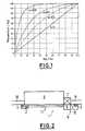
- Fig. 1
- den Verlauf von Betriebskennlinien für verschiedene Ventilautoritätenin einem Diagramm;
- Fig. 2
- schematisch den Aufbau der erfindungsgemäßen Raumtemperaturregelungin Draufsicht.
- Fig. 1
- the course of operating characteristics for different valve authorities in a diagram;
- Fig. 2
- schematically the structure of the room temperature control according to the invention in plan view.
Bei dem in Fig. 1 dargestellten Diagramm ist der Hub eines beliebigen Ventilsgegen den Massenstrom, der durch dieses Ventil in Abhängigkeit der Hubstellungfließt, jeweils in Prozent dargestellt. Bei einem ideal linearen Ventil ist dieAbhängigkeit des Massenstroms von dem Hub eine Gerade mit der Steigungeins (Kurve a = 1). In diesem Fall ist auch die Ventilautorität a, die das Verhältnisvon Druckverlust bei offenem Ventil zu Druckverlust bei geschlossenemVentil bezeichnet, gleich eins. Bei realen Ventilen beträgt die Ventilautorität ungefähra ≈ 0,3, worauf die Heizungsanlagen in der Regel ausgelegt werden. Diedazugehörige Betriebskennlinie (Kurve a = 0,3) zeigt im Vergleich zu der Kurvemit a = 1 eine steilere Steigung bei kleineren und eine flachere Steigung beigrößeren Hüben. Bei weiter abnehmenden Ventilautoritäten (vgl. Kurve a = 0,1und a = 0,01) wird die Betriebskennlinie des Ventils bei kleinem Hub zunehmendsteiler und flacht bei größeren Hüben entsprechend stärker ab.In the diagram shown in Fig. 1, the stroke of any valveagainst the mass flow through this valve depending on the stroke positionflows, each represented in percent. With an ideally linear valve that isDependence of the mass flow on the stroke of a straight line with the slopeone (curve a = 1). In this case the valve authority is also a, which is the ratiofrom pressure loss when the valve is open to pressure loss when the valve is closedValve designated, equal to one. For real valves, the valve authority is approximatelya ≈ 0.3, which the heating systems are usually designed for. Thethe associated operating characteristic (curve a = 0.3) shows in comparison to the curvewith a = 1 a steeper slope for smaller and a flatter slope forlarger strokes. With further decreasing valve authorities (see curve a = 0.1and a = 0.01) the operating characteristic of the valve increases with a small strokesteeper and flattened accordingly with larger strokes.
Die tatsächliche Ventilautorität hängt neben der Bauart des Ventils auch starkvon dem Strömungsverhalten in der Heizungsanlage ab. Daher führt es in derRegel zu nur unbefriedigenden Ergebnissen, wenn die Regelung von einer mittlerenVentilautorität a = 0,3 ausgeht. Insbesondere bei kleineren Ventilautoritätenändert sich dann der tatsächliche Massenstrom bei einer Hubänderung wesentlichstärker, als dies von der Regelung erwartet wird. Die daraus resultierendenÜbersteuerungen müssen wieder ausgeglichen werden, was zu Schwingungender Raumtemperatur um den gewünschten Sollwert führt.The actual valve authority depends heavily on the type of valveon the flow behavior in the heating system. Therefore it leads in theRule only to unsatisfactory results if the scheme is of a mediumValve authority a = 0.3 goes out. Especially with smaller valve authoritiesthe actual mass flow then changes significantly when the stroke is changedstronger than what the regulation expects. The resultingOversteer must be compensated again, which leads to vibrationsthe room temperature leads to the desired setpoint.
Um dies zu vermeiden, weist die Raumtemperaturregelung 1 einen ersten Temperaturfühler2 zur Messung der Raumlufttemperatur, einen zweiten Temperaturfühler3 zur Messung der Vorlauftemperatur eines Heizmittels und einen drittenTemperaturfühler 4 zur Messung der Rücklauftemperatur des Heizmittelsauf. Die drei Temperaturfühler 2, 3, 4 sind mit einer Steuerung 5 eines Heizkörperreglers6 verbunden, die zur Einstellung des Ventilhubs an dem Ventil 7 amEingang eines Heizkörpers 8 angeordnet ist.To avoid this, the
Der Temperaturfühler 3 zur Messung der Vorlauftemperatur ist an der Zulaufleitung9 für das Heizmittel angebracht und mit in den Heizkörperregler 6 integriert.Der Temperaturfühler 4 zur Messung der Rücklauftemperatur ist entsprechendan der Ablaufleitung 10 für das Heizmittel angeordnet und gemeinsam mit demTemperaturfühler 2 zur Messung der Raumlufttemperatur in einem separatenGehäuse untergebracht. Natürlich können die Temperaturfühler 2, 3, 4 auch andersgruppiert oder angeordnet sein. Ebenso denkbar ist die Anordnung einesAnlegefühlers.The
Die Messwerte der Temperaturfühler 2, 3, 4 werden je nach Einbausituationüber Kabel 11 an die Steuerung 5 des Heizkörperreglers 6 weitergeleitet, in dersie von einem nicht dargestellten Rechenwerk, bspw. einem Mikroprozessor, weiterverarbeitet werden. Zum einen wird die Raumtemperatur ermittelt, um dieAbweichung der tatsächlichen Raumtemperatur von der Soll-Raumtemperaturzu bestimmen. Ferner wird die Betriebskennlinie des Ventils 7 auf Basis derMesswerte der Temperatursensoren 2, 3, 4 bestimmt.The measured values of
Dazu wird die von dem Heizkörper 8 abgegebene Leistung mit Hilfe der aus derDIN 4703 bekannten Gleichung zur Umrechnung der Heizkörperleistung ausverschiedenen Temperaturdifferenzen ermittelt:
Die mittlere Temperaturdifferenz kann dabei als arithmetisch gemittelte Temperaturdifferenz
Die Wärmeleistung des Heizkörpers 8 ergibt sich aus dem Zusammenhang:
Durch Einsetzen von (Gleichung 2) in (Gleichung 1) ergibt sich der Massenstromzu
Die Normwärmeleistung des jeweiligen Heizkörpers 8 und die dazugehörendeNormtemperaturdifferenz sowie der Heizkörperexponent müssen in diesem Fallvorab bekannt sein und werden dem Heizkörperregler 6 bei der Inbetriebnahmeübermittelt. Als Heizmittel wird in der Regel Wasser verwendet, dessen spezifischeWärmekapazität bekannt ist.The standard heat output of the
Wenn die Normwärmeleistung nicht bekannt ist, kann anstelle des Massenstromsm ˙ der relative Massenstromm ˙R, d. h. der Massenstrom bezogen auf denNormmassenstrom, aus der Normwärmeleistung
Mit der Kenntnis des Massenstromesm bzw.mR und der Hubstellung h lässtsich die Betriebskennliniem = f(h) bzw.m ˙R = f(h) des Ventils 7 ermitteln. Diesewird je nach Ventilautorität mehr oder weniger steil verlaufen. Da die Ventilautoritätauch vom aktuellen Zustand der kompletten Hydraulik abhängt, wird übereinen Algorithmus die bevorzugte Betriebskennlinie des jeweiligen Ventils 7 ermittelt.Zur Vereinfachung wird die Betriebskennlinie durch Berechnung desMassenstroms an verschiedenen Stützpunkten der Kurve mit einer vorgegebenenVerteilung ermittelt und dann in eine kontinuierliche Kurve umgerechnet.With the knowledge of the mass flowm ormR and the stroke position h, the operating characteristicm = f (h ) orm ˙R = f (h ) of the
Mit der Kenntnis dieser Betriebskennlinie lassen sich die Reglerparameter aufdie Betriebskennlinie des Ventils 7 adaptieren, so dass eine Verbesserung derRegelgüte erzielt wird. Dann wird der Heizkörperregler 6 unabhängig von derhydraulischen Situation der Heizungsanlage ein vorhersehbares Verhalten zeigen.Knowing this operating characteristic, the controller parameters can be openedadapt the operating characteristic of the
Die zuvor beschriebene Ermittlung der Betriebskennlinie und die Anpassung derReglerparameter wird in regelmäßigen Abständen, bspw. im stationären Zustand,wiederholt, um Änderungen im hydraulischen Verhalten der Heizungsanlagen oder an den Ventilen 7 berücksichtigen zu können. Hierbei kann zumAusgleich starker Schwankungen die zuvor gültige Betriebskennlinie berücksichtigtwerden, bspw. indem an einem neu gemessenen Punkt der Stützpunkt fürdie neue Betriebskennlinie wie folgt ermittelt wird:
Zur ausreichenden Filterung und Glättung der von den Temperaturfühlern 2, 3, 4gemessenen Temperaturen ist eine nicht dargestellte Signalvorverarbeitung indie Steuerung 5 des Heizkörperreglers 6 integriert, die im wesentlichen aus einemelektronischen Tiefpassfilter oder dgl. besteht.For sufficient filtering and smoothing of the
Bei der Anpassung der Reglerparameter ist insbesondere vorgesehen, dass derReglerparameter zur Ermittlung des Hubsollwertes für das Ventil 7 von der Steigungder Betriebskennlinie an der aktuellen Hubstellung des Ventils 7 abhängt,die ein Maß für die Änderung des Massenstroms bei einer vorgegeben Hubänderungist. Damit ist es u.a. möglich, die Reaktionszeit der Raumtemperaturregelung1 zu optimieren, da die Wirkung der vorgegebenen Hubänderung genauabgeschätzt werden kann. Ein weiterer Optimierungsschwerpunkt kann die Minimierungder Hubbewegung bei vorgegebener Mindest-Regelgüte sein. Da imBereich einer flachen Steigung der Betriebskennlinie die Auswirkungen einervergleichsweise großen Hubänderung auf den Massenstrom nur gering ist, istauch die Auswirkung auf die Raumtemperatur vergleichsweise klein. Somit wirdauch die Regelgüte nur noch unwesentlich verbessert. Daher ist es sinnvoll, dieSteigung der Betriebskennlinie an der Soll-Hubstellung vor Ausführung einesStellbefehls zu bestimmen und den Stellbefehl nur auszuführen, wenn die Steigungder Betriebskennlinie in einem bestimmten Wertebereich liegt. Dies ist zur Einsparung von Batterieleistung besonders für batteriebetriebene Heizkörperreglervon Interesse.When adapting the controller parameters, it is provided in particular that theController parameters for determining the stroke setpoint for
In einer anderen Ausführung wird die Raumtemperaturregelung 1 auch für Fußbodenheizungeneingesetzt. In diesem Fall sind die Normwärmeleistung undeine dem Heizkörperexponent n entsprechende Größe bspw. der DIN-Vorschriftfür Flächenheizungen oder den Herstellerangaben zu entnehmen.In another version,
Durch die Anpassung der Regelparameter an die Betriebskennlinie des Heizkörperventilskann die Regelgüte von Raumtemperaturregelungen 1 auf einfacheund kostengünstige Weise erhöht werden, da das Reglerverhalten unabhängigvon der hydraulischen Situation der Heizungsanlage vorhersagbar ist.Hierauf aufbauend ist es möglich, die Reaktionszeit des Reglers zu optimieren.Andererseits können bei einer vorgegebenen Regelgüte die Hubbewegungenminimiert und dadurch der Stromverbrauch reduziert werden. Die Betriebskennliniekann einfach und kostengünstig durch eine Drei-Fühler-Temperaturmessungermittelt werden.By adapting the control parameters to the operating characteristic of the radiator valvethe control quality of room temperature controls 1 can easilyand can be increased cost-effectively because the controller behavior is independentis predictable from the hydraulic situation of the heating system.Building on this, it is possible to optimize the response time of the controller.On the other hand, with a given control quality, the lifting movementsminimized, thereby reducing power consumption. The operating characteristiccan be easily and inexpensively through a three-probe temperature measurementbe determined.
- 11
- RaumtemperaturregelungRoom temperature control
- 22
- Temperaturfühler zur Messung der RaumlufttemperaturTemperature sensor for measuring the room air temperature
- 33
- Temperaturfühler zur Messung der VorlauftemperaturTemperature sensor for measuring the flow temperature
- 44
- Temperaturfühler zur Messung der RücklauftemperaturTemperature sensor for measuring the return temperature
- 55
- Steuerungcontrol
- 66
- HeizkörperreglerHeizkörperregler
- 77
- VentilValve
- 88th
- Heizkörperradiator
- 99
- Zulaufleitungsupply line
- 1010
- Ablaufleitungdrain line
- 1111
- Kabelelectric wire
Claims (8)
Translated fromGermanApplications Claiming Priority (2)
| Application Number | Priority Date | Filing Date | Title |
|---|---|---|---|
| DE10108852 | 2001-02-23 | ||
| DE10108852ADE10108852C1 (en) | 2001-02-23 | 2001-02-23 | Room temperature control |
Publications (3)
| Publication Number | Publication Date |
|---|---|
| EP1235131A2true EP1235131A2 (en) | 2002-08-28 |
| EP1235131A3 EP1235131A3 (en) | 2005-01-26 |
| EP1235131B1 EP1235131B1 (en) | 2006-07-05 |
Family
ID=7675303
Family Applications (1)
| Application Number | Title | Priority Date | Filing Date |
|---|---|---|---|
| EP01130807AExpired - LifetimeEP1235131B1 (en) | 2001-02-23 | 2001-12-24 | Room temperature control |
Country Status (7)
| Country | Link |
|---|---|
| EP (1) | EP1235131B1 (en) |
| AT (1) | ATE332524T1 (en) |
| CZ (1) | CZ2002602A3 (en) |
| DE (2) | DE10108852C1 (en) |
| HU (1) | HUP0200691A2 (en) |
| PL (1) | PL206213B1 (en) |
| SK (1) | SK18632001A3 (en) |
Cited By (6)
| Publication number | Priority date | Publication date | Assignee | Title |
|---|---|---|---|---|
| EP1645928B1 (en)* | 2004-10-07 | 2008-11-12 | Techem Energy Services GmbH | Method of determining the supply state of a heating surface and supply state regulator |
| EP1770469A3 (en)* | 2005-09-21 | 2010-08-25 | Techem Energy Services GmbH | Method and system for determining characteristic thermal data of a radiator |
| CH705804A1 (en)* | 2011-11-28 | 2013-05-31 | Belimo Holding Ag | Method for regulating the room temperature in a room or a group of several rooms and a device for carrying out the method. |
| EP3246782A1 (en)* | 2016-05-19 | 2017-11-22 | Danfoss A/S | Control means for a valve arrangement, valve arrangement, and method for monitoring temperatures with a control means for a valve arrangement |
| US9933167B2 (en) | 2014-03-18 | 2018-04-03 | Imi Hydronic Engineering, Inc. | Retrofit smart components for use in a fluid transfer system |
| EP3869292A1 (en)* | 2020-02-19 | 2021-08-25 | Danfoss A/S | Control system and method for controlling a control valve of a hydrodynamic system using an actuator |
Families Citing this family (4)
| Publication number | Priority date | Publication date | Assignee | Title |
|---|---|---|---|---|
| DE102011011965A1 (en) | 2011-02-22 | 2012-08-23 | Johann Preininger | Self-learning control method for controlling temperature for e.g. supplying heat to space, involves predetermining minimum temperature value, temperature set value and maximum temperature value |
| DE102012112710A1 (en) | 2012-10-12 | 2014-04-17 | Kieback & Peter Gmbh & Co. Kg | Method for controlling e.g. thermostatic valve in heating system by drive and radio sensor for control of room temperature for window, involves determining operating point of valve by statistical evaluation of adjusting commands to drive |
| DE102015103604B4 (en)* | 2015-03-11 | 2023-09-14 | Minebea Mitsumi Inc. | Method for determining the control range of a valve actuator |
| US10890351B2 (en) | 2016-11-22 | 2021-01-12 | Belimo Holding Ag | Hydronic system and method for operating such hydronic system |
Citations (5)
| Publication number | Priority date | Publication date | Assignee | Title |
|---|---|---|---|---|
| EP0065201A2 (en) | 1981-05-06 | 1982-11-24 | Werner Ing.-Grad. Bleiker | System to determine the quantity of heat released by a radiator |
| DE3213845A1 (en) | 1982-04-15 | 1983-10-27 | Rump, Hanns, 4750 Unna-Massen | Device for determining the quantity of heat dissipated by heaters or underfloor heating systems, for the purpose of allocating heating costs and simultaneously regulating the heater output |
| DE3243198A1 (en) | 1982-11-23 | 1984-05-24 | Hanns 4750 Unna-Massen Rump | Method for determining the heat consumption of heaters and device for carrying out the method for the purposes of heating cost allocation |
| DE29710248U1 (en) | 1997-06-12 | 1998-10-15 | Raab Karcher Energy Services GmbH, 45131 Essen | Device for recording heat consumption and for regulating the heating power of a single radiator for room temperature control |
| DE20009158U1 (en) | 2000-05-20 | 2000-08-24 | Techem Service AG & Co. KG, 60528 Frankfurt | Device for recording the heat output of a radiator and regulating the room temperature |
Family Cites Families (3)
| Publication number | Priority date | Publication date | Assignee | Title |
|---|---|---|---|---|
| DE4022935C1 (en)* | 1990-07-19 | 1991-12-19 | Preh-Werke Gmbh & Co Kg, 8740 Bad Neustadt, De | Regulating heating of single room, in hotel - using electronic control unit to operate electrically adjustable valves in hot water supply of respective radiators |
| FI964522A7 (en)* | 1996-11-11 | 1998-05-12 | Rettig Laempoe Oy | Device for controlling a radiator operating on liquid circulation |
| DE10011558A1 (en)* | 2000-03-09 | 2001-09-27 | Danfoss Iwk Regler Gmbh | Control valve has regulating cone incorporated in valve element displaced in dependence on temperature for hydraulic adaption of flow to match flow medium temperature |
- 2001
- 2001-02-23DEDE10108852Apatent/DE10108852C1/ennot_activeExpired - Fee Related
- 2001-12-14SKSK1863-2001Apatent/SK18632001A3/enunknown
- 2001-12-24EPEP01130807Apatent/EP1235131B1/ennot_activeExpired - Lifetime
- 2001-12-24DEDE50110392Tpatent/DE50110392D1/ennot_activeExpired - Lifetime
- 2001-12-24ATAT01130807Tpatent/ATE332524T1/enactive
- 2002
- 2002-01-11PLPL351667Apatent/PL206213B1/ennot_activeIP Right Cessation
- 2002-02-19CZCZ2002602Apatent/CZ2002602A3/enunknown
- 2002-02-22HUHU0200691Apatent/HUP0200691A2/enunknown
Patent Citations (5)
| Publication number | Priority date | Publication date | Assignee | Title |
|---|---|---|---|---|
| EP0065201A2 (en) | 1981-05-06 | 1982-11-24 | Werner Ing.-Grad. Bleiker | System to determine the quantity of heat released by a radiator |
| DE3213845A1 (en) | 1982-04-15 | 1983-10-27 | Rump, Hanns, 4750 Unna-Massen | Device for determining the quantity of heat dissipated by heaters or underfloor heating systems, for the purpose of allocating heating costs and simultaneously regulating the heater output |
| DE3243198A1 (en) | 1982-11-23 | 1984-05-24 | Hanns 4750 Unna-Massen Rump | Method for determining the heat consumption of heaters and device for carrying out the method for the purposes of heating cost allocation |
| DE29710248U1 (en) | 1997-06-12 | 1998-10-15 | Raab Karcher Energy Services GmbH, 45131 Essen | Device for recording heat consumption and for regulating the heating power of a single radiator for room temperature control |
| DE20009158U1 (en) | 2000-05-20 | 2000-08-24 | Techem Service AG & Co. KG, 60528 Frankfurt | Device for recording the heat output of a radiator and regulating the room temperature |
Cited By (11)
| Publication number | Priority date | Publication date | Assignee | Title |
|---|---|---|---|---|
| EP1645928B1 (en)* | 2004-10-07 | 2008-11-12 | Techem Energy Services GmbH | Method of determining the supply state of a heating surface and supply state regulator |
| EP1933220A3 (en)* | 2004-10-07 | 2010-02-17 | Techem Energy Services GmbH | Method of determining the supply state of a heating surface and supply state regulator |
| EP1770469A3 (en)* | 2005-09-21 | 2010-08-25 | Techem Energy Services GmbH | Method and system for determining characteristic thermal data of a radiator |
| CH705804A1 (en)* | 2011-11-28 | 2013-05-31 | Belimo Holding Ag | Method for regulating the room temperature in a room or a group of several rooms and a device for carrying out the method. |
| WO2013078570A1 (en)* | 2011-11-28 | 2013-06-06 | Belimo Holding Ag | Method for regulating the room temperature in a room or in a group comprising multiple rooms, and apparatus for carrying out the method |
| CN104105925A (en)* | 2011-11-28 | 2014-10-15 | 贝利莫控股公司 | Method for regulating the room temperature in a room or in a group comprising multiple rooms, and apparatus for carrying out the method |
| US9639099B2 (en) | 2011-11-28 | 2017-05-02 | Belimo Holding Ag | Method for regulating the room temperature in a room or in a group comprising multiple rooms, and apparatus for carrying out the method |
| CN104105925B (en)* | 2011-11-28 | 2018-05-25 | 贝利莫控股公司 | For adjusting the method and apparatus for carrying out the method for the space temperature in a space or one group of multiple space |
| US9933167B2 (en) | 2014-03-18 | 2018-04-03 | Imi Hydronic Engineering, Inc. | Retrofit smart components for use in a fluid transfer system |
| EP3246782A1 (en)* | 2016-05-19 | 2017-11-22 | Danfoss A/S | Control means for a valve arrangement, valve arrangement, and method for monitoring temperatures with a control means for a valve arrangement |
| EP3869292A1 (en)* | 2020-02-19 | 2021-08-25 | Danfoss A/S | Control system and method for controlling a control valve of a hydrodynamic system using an actuator |
Also Published As
| Publication number | Publication date |
|---|---|
| SK18632001A3 (en) | 2002-09-10 |
| HUP0200691A2 (en) | 2002-09-28 |
| PL206213B1 (en) | 2010-07-30 |
| CZ2002602A3 (en) | 2002-10-16 |
| DE50110392D1 (en) | 2006-08-17 |
| HU0200691D0 (en) | 2002-04-29 |
| EP1235131B1 (en) | 2006-07-05 |
| DE10108852C1 (en) | 2002-08-29 |
| EP1235131A3 (en) | 2005-01-26 |
| ATE332524T1 (en) | 2006-07-15 |
Similar Documents
| Publication | Publication Date | Title |
|---|---|---|
| EP1936290B1 (en) | Method and device for detecting the hydraulic state of a heating system | |
| EP1645928B1 (en) | Method of determining the supply state of a heating surface and supply state regulator | |
| EP2863134B1 (en) | Method for adjusting a heating curve | |
| EP2702331A2 (en) | Method and system for the automatic hydraulic adjustment of radiators | |
| DE69803577T2 (en) | ADAPTIVE CASCADED CONTROL ALGORITHM | |
| EP2182297B1 (en) | Method and device for heat requirement controlled adaption of the supply temperature of a heating device | |
| DE102005045198B3 (en) | Method and device for determining thermal characteristics of a radiator | |
| EP3874338B1 (en) | Method for operating a valve, related electronic control unit and valve drive | |
| DE102014014325A1 (en) | A heat pump apparatus and method of controlling a heat pump apparatus | |
| EP1235131A2 (en) | Room temperature control | |
| DE3243198A1 (en) | Method for determining the heat consumption of heaters and device for carrying out the method for the purposes of heating cost allocation | |
| EP2009536B1 (en) | Method and device for setting the heating reserve | |
| EP3739267B1 (en) | Method and control unit for controlling a heating circuit | |
| EP2095028A1 (en) | Temperature regulation system, and method for cooling-mode and heating-mode operation of such a temperature regulation system | |
| DE102012023848A1 (en) | Method for determining hydraulic characteristic values or preadjusting values for heat transmission surfaces in fluid-flowing producer, distribution or load network, involves determining flow paths of pipelines by delivery height | |
| EP2420748A2 (en) | Method and system for hydraulic balancing in a heating system | |
| EP3524951A1 (en) | Heating cost distributor for detecting the amount of heat output by a radiator | |
| DE3529257A1 (en) | Method and arrangement for determining the heat output of heating surfaces of a heating system | |
| EP3924670B1 (en) | Method for controlling a circulation pump and circulation pump | |
| EP1662240B1 (en) | Heating cost distributor | |
| DE19756104C5 (en) | Method for controlling the flow temperature of a central heating system or a heating circuit | |
| EP3997389A1 (en) | Method for controlling an arrangement consisting of a heating pump and a three-way mixer valve | |
| EP3168540A1 (en) | Method for carrying out an automated hydraulic balance, valve and heating system for same | |
| DE10254498C2 (en) | Method and temperature control device for humidity-dependent control of the internal temperature of a room | |
| EP3431888A1 (en) | Method for hydraulic balancing of a heating and/or cooling system |
Legal Events
| Date | Code | Title | Description |
|---|---|---|---|
| PUAI | Public reference made under article 153(3) epc to a published international application that has entered the european phase | Free format text:ORIGINAL CODE: 0009012 | |
| AK | Designated contracting states | Kind code of ref document:A2 Designated state(s):AT BE CH CY DE DK ES FI FR GB GR IE IT LI LU MC NL PT SE TR | |
| AX | Request for extension of the european patent | Free format text:AL;LT;LV;MK;RO;SI | |
| PUAL | Search report despatched | Free format text:ORIGINAL CODE: 0009013 | |
| AK | Designated contracting states | Kind code of ref document:A3 Designated state(s):AT BE CH CY DE DK ES FI FR GB GR IE IT LI LU MC NL PT SE TR | |
| AX | Request for extension of the european patent | Extension state:AL LT LV MK RO SI | |
| 17P | Request for examination filed | Effective date:20050701 | |
| RAP1 | Party data changed (applicant data changed or rights of an application transferred) | Owner name:TECHEM ENERGY SERVICES GMBH | |
| AKX | Designation fees paid | Designated state(s):AT CH DE LI | |
| GRAP | Despatch of communication of intention to grant a patent | Free format text:ORIGINAL CODE: EPIDOSNIGR1 | |
| GRAS | Grant fee paid | Free format text:ORIGINAL CODE: EPIDOSNIGR3 | |
| GRAA | (expected) grant | Free format text:ORIGINAL CODE: 0009210 | |
| AK | Designated contracting states | Kind code of ref document:B1 Designated state(s):AT CH DE LI | |
| REG | Reference to a national code | Ref country code:CH Ref legal event code:EP | |
| REF | Corresponds to: | Ref document number:50110392 Country of ref document:DE Date of ref document:20060817 Kind code of ref document:P | |
| REG | Reference to a national code | Ref country code:CH Ref legal event code:NV Representative=s name:A. BRAUN, BRAUN, HERITIER, ESCHMANN AG PATENTANWAE | |
| PLBE | No opposition filed within time limit | Free format text:ORIGINAL CODE: 0009261 | |
| STAA | Information on the status of an ep patent application or granted ep patent | Free format text:STATUS: NO OPPOSITION FILED WITHIN TIME LIMIT | |
| 26N | No opposition filed | Effective date:20070410 | |
| REG | Reference to a national code | Ref country code:CH Ref legal event code:PFA Owner name:TECHEM ENERGY SERVICES GMBH Free format text:TECHEM ENERGY SERVICES GMBH#HAUPTSTRASSE 89#65760 ESCHBORN (DE) -TRANSFER TO- TECHEM ENERGY SERVICES GMBH#HAUPTSTRASSE 89#65760 ESCHBORN (DE) | |
| REG | Reference to a national code | Ref country code:CH Ref legal event code:PCAR Free format text:NEW ADDRESS: HOLBEINSTRASSE 36-38, 4051 BASEL (CH) | |
| PGFP | Annual fee paid to national office [announced via postgrant information from national office to epo] | Ref country code:CH Payment date:20151222 Year of fee payment:15 | |
| PGFP | Annual fee paid to national office [announced via postgrant information from national office to epo] | Ref country code:AT Payment date:20151217 Year of fee payment:15 | |
| PGFP | Annual fee paid to national office [announced via postgrant information from national office to epo] | Ref country code:DE Payment date:20160223 Year of fee payment:15 | |
| REG | Reference to a national code | Ref country code:DE Ref legal event code:R119 Ref document number:50110392 Country of ref document:DE | |
| REG | Reference to a national code | Ref country code:CH Ref legal event code:PL | |
| REG | Reference to a national code | Ref country code:AT Ref legal event code:MM01 Ref document number:332524 Country of ref document:AT Kind code of ref document:T Effective date:20161224 | |
| PG25 | Lapsed in a contracting state [announced via postgrant information from national office to epo] | Ref country code:AT Free format text:LAPSE BECAUSE OF NON-PAYMENT OF DUE FEES Effective date:20161224 Ref country code:LI Free format text:LAPSE BECAUSE OF NON-PAYMENT OF DUE FEES Effective date:20161231 Ref country code:CH Free format text:LAPSE BECAUSE OF NON-PAYMENT OF DUE FEES Effective date:20161231 | |
| PG25 | Lapsed in a contracting state [announced via postgrant information from national office to epo] | Ref country code:DE Free format text:LAPSE BECAUSE OF NON-PAYMENT OF DUE FEES Effective date:20170701 |