EP1234549A1 - Lingual bracket - Google Patents
Lingual bracketDownload PDFInfo
- Publication number
- EP1234549A1 EP1234549A1EP01103452AEP01103452AEP1234549A1EP 1234549 A1EP1234549 A1EP 1234549A1EP 01103452 AEP01103452 AEP 01103452AEP 01103452 AEP01103452 AEP 01103452AEP 1234549 A1EP1234549 A1EP 1234549A1
- Authority
- EP
- European Patent Office
- Prior art keywords
- slot
- bracket
- base plate
- wire
- straightening wire
- Prior art date
- Legal status (The legal status is an assumption and is not a legal conclusion. Google has not performed a legal analysis and makes no representation as to the accuracy of the status listed.)
- Withdrawn
Links
Images


Classifications
- A—HUMAN NECESSITIES
- A61—MEDICAL OR VETERINARY SCIENCE; HYGIENE
- A61C—DENTISTRY; APPARATUS OR METHODS FOR ORAL OR DENTAL HYGIENE
- A61C7/00—Orthodontics, i.e. obtaining or maintaining the desired position of teeth, e.g. by straightening, evening, regulating, separating, or by correcting malocclusions
- A61C7/12—Brackets; Arch wires; Combinations thereof; Accessories therefor
- A61C7/28—Securing arch wire to bracket
- A61C7/30—Securing arch wire to bracket by resilient means; Dispensers therefor
- A—HUMAN NECESSITIES
- A61—MEDICAL OR VETERINARY SCIENCE; HYGIENE
- A61C—DENTISTRY; APPARATUS OR METHODS FOR ORAL OR DENTAL HYGIENE
- A61C7/00—Orthodontics, i.e. obtaining or maintaining the desired position of teeth, e.g. by straightening, evening, regulating, separating, or by correcting malocclusions
- A61C7/12—Brackets; Arch wires; Combinations thereof; Accessories therefor
- A61C7/14—Brackets; Fixing brackets to teeth
- A61C7/145—Lingual brackets
- A—HUMAN NECESSITIES
- A61—MEDICAL OR VETERINARY SCIENCE; HYGIENE
- A61C—DENTISTRY; APPARATUS OR METHODS FOR ORAL OR DENTAL HYGIENE
- A61C7/00—Orthodontics, i.e. obtaining or maintaining the desired position of teeth, e.g. by straightening, evening, regulating, separating, or by correcting malocclusions
- A61C7/12—Brackets; Arch wires; Combinations thereof; Accessories therefor
- A61C7/28—Securing arch wire to bracket
- A61C7/285—Locking by rotation
Definitions
- the inventionrelates to a lingual bracket for orthodontic treatments the upper and lower front and canine teeth, consisting of one Base plate for adhesive attachment to the lingual side of a tooth with each other opposite occlusal and gingival margins and opposite mesial and distal edges, one rising from the base plate Structure with an essentially parallel to the occlusal and Gingival edges extending slot for receiving a straightening wire and if necessary with at least one device movably mounted on the body partial coverage of those extending parallel to the edges mentioned Slot opening.
- bracketsare attached to the teeth, through a slot in the brackets, which varies depending on the tooth inserted elastic straightening wire as if the pearls of a chain with each other get connected.
- the straightening wiregenerates due to the fact that it is also on the other teeth by brackets is held on the bracket on the tooth in question, forces with "angulation”, “Rotation” and “Torque” are referred to.
- Correct angulation forcesa lateral inclination of the tooth, rotational forces virtually turn the tooth its axis and torque forces pivot the tooth across the row of teeth, i.e.
- a three-dimensional correction of the position of aoccurs every single tooth. On the different directions of correction received later.
- a bracket of the type mentionedis known from US 5 863 199.
- This Documentdescribes a lingual orthodontic bracket in which the Device for covering or closing the slit used for the reception the straightening wire is determined, an articulated on the structure around a bearing pin mounted lever, which is held in its closed position by ligatures must be around this lever and a nose formed on the structure be looped.
- the slotis formed on the bracket such that its Opening points towards the gingiva. This means that the orthodontist is the Straightening wire from the back of the bracket facing away from it into the slot must insert. This can only be checked indirectly using a mirror.
- the straightening wire when biting into a foodis the pressure of the food in question exposed in a direction that leads out of the slot so that the straightening wire would be pushed out of the slot when said lever opened.
- the ligaturesmust therefore be very reliable in order to open the over prevent the closing device located in the slot.
- a bracketwhich is both labial and lingual can be used. It has a very flat construction, in which the slot for Pick-up of a straightening wire essentially perpendicularly away from the base plate has. The slot is covered by a striking plate, which is supported by a spring in one Is held in the closed position.
- a disadvantage of this constructionis that the pressure applied to the straightening wire, which is the result of lingual application of the bracket often inside, d. H. is directed towards the oral cavity from the locking plate and whose spring they are held in the closed position got to.
- the support of the straightening wireis therefore not rigid, but to a certain extent Way elastic, what the forces required for the rotation of a tooth is not sufficiently developed.
- a lingual orthodontic bracketis known from US Pat. No. 6,142,776 Slit is oriented similarly to that in the bracket according to US Pat. No. 5,863,199.
- Only ligaturesare used to secure the straightening wire with this bracket provided in the form of highly elastic O-rings (usually made of rubber), so that this bracket both in use and when changing the straightening wire has similar disadvantages as the aforementioned.
- bracketsare known from US 4,455,137.
- the slotis with them open on the side of the body facing away from the base plate, and the straightening wire is to be secured with ligatures in the slot, so that this bracket has these disadvantages having the last two brackets from US 5 857 849 and 6 142 776 are peculiar.
- brackets from US 4,337,037 and 4,669,981have become known.
- US 5,516,284describes a lingual orthodontic bracket, the Slit covered by a locking arrangement pivotally mounted on the body can be, which consists of a metal strip that is bent into a U-shape Has section that is mounted on the structure and the two legs unequal long and bent again in a C-shape. In the closed position, the shorter of these C-shaped legs the slot, while the other C-shaped Leg secured to a horn formed on the structure by means of a ligature must become.
- the overall structure of this bracketis relatively high, and that Opening of the slot lies, comparable to the bracket according to the aforementioned US 5 863 199, on the side facing away from the surgeon.
- the inventionhas for its object a bracket of the type mentioned specify in which the straightening wire can be inserted easily and in a time-saving manner where the straightening wire is held securely and on which the straightening wire is effective can exercise in the best possible way.
- the inventionprovides a bracket in which the slot is directed so that the Have the straightening wire inserted into it from the occlusal side (chewing level).
- the insertion the straightening wirecan therefore be very easily without the aid of a mirror check.
- the straightening wireis secured in the slot by a ligature or by a spring, in particular by one between two positions can be pivoted in a manner known per se, being in one Position releases the slot and covers the slot in the other position.
- a ligature or by a springin particular by one between two positions can be pivoted in a manner known per se, being in one Position releases the slot and covers the slot in the other position.
- US 5,562,444exemplary for this purpose, reference is made to US 5,562,444.
- Straightening wire on the bracket and thus the treated toothhas a rotating effect not by any elastic closing or holding mechanisms, like feathers or ligatures, but taken up unaffected by the bracket structure and transferred to the tooth.
- the canine areais where the straightening forces act in a plane that is not perpendicular runs to the base of the bracket, but essentially parallel to the chewing plane. In this direction, however, the straightening wire is not from the locking mechanism of the bracket, i.e. the ligature or the spring, but from at least one side wall supported the slot receiving the straightening wire.
- the slit levelmeans a level that extends essentially perpendicular to the slot base. Accordingly, for one orthodontic treatment requires a set of brackets that different, brackets designed for the different teeth in the anterior and canine area having. Brackets for the molars, on the other hand, are designed differently and are not the subject of this invention.
- the bracket according to the inventiondiffers from all known linguals Brackets in that the slot is open to the chewing level and preferably is less deep than wide.
- a straightening wire with a rectangular cross-sectionis therefore included its broad side inserted into the slot almost flat, while all known lingual brackets the straightening wire with its narrow side, so to speak upright with respect to the slot in which the slot is inserted.
- the ligature or the closing springpresses the wide side of the straightening wire on the slot base in one direction depending on Misalignment of the tooth is more or less perpendicular to the chewing plane.
- the closing mechanismscan be elastic Do not apply forces.
- the straightening wireis under the influence of the force of the ligature from the beginning or the spring and is therefore effective on the tooth.
- the straightening wire of a rotated toothlies on two diagonally opposite ones Edges at the ends of the slot and exerts pressure there, so that the elasticity of the wire on the bracket causes rotational forces that immediately act on the bracket and are thus transferred to the tooth.
- Thisis particularly important for the brackets for the front teeth of the lower jaw, because of the small dimensions of the teeth, the brakets used there are very narrow and therefore the leverage is very low.
- Elastic supports, through O-rings, as in the prior art,would have the effect of the straightening wire in this area reduce significantly and often only insufficient Develop forces to correct a rotation. Avoids this disadvantage The invention.
- a particular advantage of the inventionthat of the created by the invention Location of the slot opening results, is also that on locking lugs for the free end of the closing spring, where such is used instead of a ligature, can be dispensed with and for the brackets for the upper front teeth and if necessary is advantageously also actually dispensed with for the upper canine teeth.
- These bracketsare therefore extremely flat, which is important to prevent when closing the jaws, the lower ones, which reach behind the upper front teeth Front teeth hit the brackets attached to the upper front teeth.
- Such a securing lugis known, for example, from US Pat. No. 4,492,573 and to the bracket shown there is indispensable, because the opening and closing movement the U-shaped spring there, one leg of which the slot covered, runs transversely to the direction in which the straightening wire leaves the slot would. If the straightening wire, for whatever reason, is in the spring-closed position would be pushed out of the slot, then he would over the feather bend their elastic limit and thus destroy the entire bracket, if the free end of the spring leg covering the slot is not would be secured under a protruding nose.
- a straightening wire pushing out of the slotacts in the opening direction the closing spring on this and only pivots it without closing it to destroy.
- the locking noseis therefore basically unnecessary with this bracket. Where it is used, for example in the canine area, it serves there, on the one hand, the increase in resistance to pressing out the Straightening wire from the slot, on the other hand, is exceeded when a certain Force released the wire and thus the tooth automatically from overload protected. With this nose, the desired opening resistance of the Spring are generated.
- the structure 3has two wings 5 and 6, which adjoin the side walls of the slot 4 and can be used to attach ligatures.
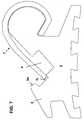
- a spring designated 7 overallhere a leaf spring, which has an arcuate section 7a which extends over an arc of approximately Extends 270 ° and merges into an approximately rectilinear section 7b, the End area covers the slot 4 in the closed state of the spring 7, as in FIG. 1 shown.
- the arcuate portion 7a of the springwraps around the wing 6 of the Structure 3.
- the springholds itself on the structure 3 by its own preload in a state covering the slot 4.
- the spring 7can also be a Wire clip spring, as described in DE 44 07 100 C2.
- the spring 7 from the state shown in Fig. 1 in one the slot 4 releasing statecan be pivoted about the wing 6.
- a groove 8is formed on the structure 3 below the wing 6, within the end region adjoining the arcuate section 7a 7d of the spring 7 can move pivotally. 2 shows in broken lines, how the spring would behave if they were largely relaxed could. You can see from the solid lines that the spring in the in Fig. 2 opening state shown is slightly bent. In this state, it backs up clamping itself on the wing 6 of the bracket.
- the grooves 2serve to hold adhesive or cement with which the bracket is attached to the tooth, the dovetail shape of the groove cross sections improves the adhesion of the adhesive or cement.
- the special properties of the bracketare those for those sought by the invention Effects are relevant are determined by the fact that the slot 4 has an orientation such that one is perpendicular to the slot base 4a standing, imaginary plane that is parallel to the longitudinal extent of the slot 4 runs and is designated in Fig. 1 with V, with one of the base of the Base plate 1 certain level B forms an acute angle ⁇ , the apex points in the direction of the gingival edge G of the base plate 1, so that the Slot base 4a opposite opening of the slot 4 substantially in Direction of the occlusal edge O of the base plate 1 of the bracket points.
- Fig. 3ain which a row of teeth One and two front teeth 11 and 12, canine tooth 13 and two molars 14 and 15 with brackets attached to it is shown schematically.
- the angles that define the base surfaces of the bracket base plates with a perpendicularinclude on the occlusal plane, for example in the bracket for the upper front teeth approx. 45 °, for the lower front teeth approx. 30 ° and for all four Canines approx. 35 °.
- the inclination of said plane Vis also every Bracket determined against the base plate level B.
- Fig. 3aIt can be seen from Fig. 3a that the insertion of a straightening wire into the bracket slots observed very easily from the chewing level on the anterior and canine teeth can be.
- the straightening wireUsed for example on the lower jaw, the straightening wire can thus be used insert into the bracket slots in the anterior and canine area comfortably from above and watch, and then the closing springs can be reliably close over the straightening wire in the slots.
- FIG. 4is a bracket according to the invention with inserted in its slot 4 straightening wire 9, the closing spring for better explanation of the invention has partially broken away.
- Fig. 4looks in Fig. 4 from the chewing level onto the backet, i.e. on the arch in which the straightening wire 9 runs along the teeth of the row of teeth. 3 clearly shows that the straightening wire 9 bears against the side walls 4b and 4c delimiting the slot 4 and is rigidly supported by these, so that it has both its rotational forces for rotating the tooth about its axis as well as its torque forces for pivoting of the tooth directly onto the bracket transversely to its axis can.
- FIG. 5shows a bracket attached to a Tooth is fixed, which has an angulation deformity and transversely to its in Fig. 5 dash-dotted in the direction of arrow A are corrected got to.
- FIG. 5shows the view from the rear of the tooth 12 in FIG. 3, that is to say in parallel seen to the chewing plane against the tooth.
- the straightening wirelies in this incorrect position 9 in the slot 4 of the bracket according to the invention not flat on the slot base 4a, but only touches the slot base 4a at its mesial or distal end, depending on the misalignment of the tooth.
- This contact areais in FIG. 5 marked with P.
- the spring 7presses due to the inherent bias on the straightening wire 9 at the point Q in the direction of the slot base 4a. Since the spring 7 is supported on the underside of the wing 6 and this one exerts upward force, but the straightening wire does not work in the opposite direction Direction, this has the consequence that one on the tooth Force is exerted on it perpendicular to the tooth axis and slot extension extending axis rotates in a direction which in Fig. 5 with "A" (for angulation force) is drawn.
- the toothgradually stands up so that the angle ⁇ , the directional wire 9 with the slot base 4a in the direction of the longitudinal extent of the slot 4 includes, gets smaller and smaller until the straightening wire 9 at the end of Treatment ideally rests flat on the slot base 4a.
- the slotcan be kept relatively "flat”, i.e. can be less deep than wide, so that a straightening wire 9 even when he Slot 4 does not fill in its entire width, i.e. a straightening wire 9 of small cross-sectional dimensions of the "family" straightening wire discussed above, about which Slot opening protrudes and from the closing spring 7 (or one in its place force is applied via wings 5 and 5 looped ligature).
- the small slot depthallows the bracket to be made very low.
- bracket according to the inventionin the lingual direction only rounded parts, namely each the arcuate area of the Closing springs, which are exposed to the annoyance of the patient by the brakkets minimized.
- FIG. 7shows a second embodiment of a bracket according to the invention, the differs from that of FIG. 1 in that it has a wing 5 has nose-like projection 5a, which extends over the free end 7c of the closing spring 7 extends. It prevents the spring 7 from starting from an approximately straightening wire
- the pressure in the opening directionimmediately gives way. It is dimensioned so that the spring 7 can yield when a certain limit is established. Consequently the forces that can act on the tooth are limited, which in turn causes the Tooth is protected against overload.
- the powersare similar to that of the orthodontist when opening the closing spring 7 with an opening 10 (see Fig. 4) the closing spring 7 inserted instrument, such as a hook, on the closing spring exercises.
- This bracketcan be used for example on the canines where the extremely flat design of the bracket is not so important.
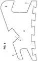
- FIG. 8shows a side view of a bracket according to the invention, the has no spring for securing the straightening wire in the slot 4 and therefore only for use in combination with an elastic ligature, for example in the form of an O-ring 16 made of rubber, known type is, which is looped over the straightening wire 9 and the wings 5 and 6 and the Holding wire in the slot 4 and presses it on the slot base 4a.
- an elastic ligaturefor example in the form of an O-ring 16 made of rubber, known type is, which is looped over the straightening wire 9 and the wings 5 and 6 and the Holding wire in the slot 4 and presses it on the slot base 4a.
- the orientation of the slot 4is as in the previously described Embodiments, so that a straightening wire 9 of rectangular cross-sectional dimensions, as shown here, "flat", with its wider side, is placed on the slot base 4a to then with the ligature 16 in its Position to be secured.
Landscapes
- Health & Medical Sciences (AREA)
- Oral & Maxillofacial Surgery (AREA)
- Dentistry (AREA)
- Epidemiology (AREA)
- Life Sciences & Earth Sciences (AREA)
- Animal Behavior & Ethology (AREA)
- General Health & Medical Sciences (AREA)
- Public Health (AREA)
- Veterinary Medicine (AREA)
- Dental Tools And Instruments Or Auxiliary Dental Instruments (AREA)
Abstract
Description
Translated fromGermanDie Erfindung bezieht sich auf ein linguales Bracket für kieferorthopädische Behandlungender oberen und unteren Front- und Eckzähne, bestehend aus einerGrundplatte zur klebenden Befestigung an der lingualen Seite eines Zahns mit einanderentgegengesetzten okklusalen und gingivalen Rändern und einander entgegengesetztenmesialen und distalen Rändern, einem sich von der Grundplatte erhebendenAufbau mit einem sich im wesentlichen parallel zu den okklusalen undgingivalen Rändern erstreckenden Schlitz zur Aufnahme eines Richtdrahtes undggf. mit einer an dem Aufbau beweglich gelagerten Einrichtung zum wenigstensteilweisen Überdecken der sich parallel zu den genannten Rändern erstreckendenSchlitzöffnung.The invention relates to a lingual bracket for orthodontic treatmentsthe upper and lower front and canine teeth, consisting of oneBase plate for adhesive attachment to the lingual side of a tooth with each otheropposite occlusal and gingival margins and oppositemesial and distal edges, one rising from the base plateStructure with an essentially parallel to the occlusal andGingival edges extending slot for receiving a straightening wire andif necessary with at least one device movably mounted on the bodypartial coverage of those extending parallel to the edges mentionedSlot opening.
Die Zähne des natürlichen menschlichen Gebisses können verschiedene Fehlstellungenaufweisen. Zur Korrektur derselben werden an den Zähnen Brackets angebracht,die durch einen in die je nach Zahn unterschiedlichen Schlitze der Bracketseingelegten elastischen Richtdraht gleichsam wie die Perlen einer Kette miteinanderverbunden werden. Je nach Fehlstellung des Zahns erzeugt der Richtdrahtaufgrund der Tatsache, daß er an den anderen Zähnen ebenfalls durch Bracketsfestgehalten ist, über das Bracket an dem betreffenden Zahn Kräfte, die mit "Angulation","Rotation" und "Torque" bezeichnet werden. Angulationskräfte korrigiereneine seitliche Schiefstellung des Zahns, Rotationskräfte drehen den Zahn quasi umseine Achse und Torque-Kräfte schwenken den Zahn quer zur Zahnreihe, d.h. umeine Achse, die quer zur Zahnachse und im wesentlichen parallel zur Zahnreiheverläuft, um beispielsweise eine Progenie, einen Kreuzbiß oder einen Vorbiss zukorrigieren. Es kommt dabei zu einer dreidimensionalen Korrektur der Stellung einesjeden einzelnen Zahnes. Auf die verschiedenen Korrektur-Richtungen wirdspäter noch eingegangen.The teeth of natural human teeth can have different misalignmentsexhibit. To correct them, brackets are attached to the teeth,through a slot in the brackets, which varies depending on the toothinserted elastic straightening wire as if the pearls of a chain with each otherget connected. Depending on the misalignment of the tooth, the straightening wire generatesdue to the fact that it is also on the other teeth by bracketsis held on the bracket on the tooth in question, forces with "angulation","Rotation" and "Torque" are referred to. Correct angulation forcesa lateral inclination of the tooth, rotational forces virtually turn the toothits axis and torque forces pivot the tooth across the row of teeth, i.e. aroundan axis that is transverse to the tooth axis and substantially parallel to the row of teethruns, for example, to a progeny, a cross bite or a pre-bitecorrect. A three-dimensional correction of the position of a occursevery single tooth. On the different directions of correctionreceived later.
Bei der Behandlung von Zahnfehlstellungen mit Hilfe von Brackets wird anfänglichein relativ dünner Richtdraht verwendet, weil zunächst geringe Korrekturkräfte anden Zähnen ausreichen und zu große Korrekturkräfte Schmerzen hervorrufen würden.Mit zunehmender Annäherung der Zähne an die Sollstellung aufgrund fortschreitenden Behandlungserfolgs müssen immer dickere Drähte verwendet werden,um die notwendigen Korrekturkräfte an den Zähnen aufzubringen. Der Richtdrahtwird im Zuge der Behandlung bis zu zehnmal ausgetauscht.When treating misaligned teeth with the help of brackets, it starts witha relatively thin straightening wire is used because initially low correction forces are appliedteeth would suffice and excessive correction forces would cause pain.With increasing approach of the teeth to the target position due to progressiveSuccessful treatment must always use thicker wiresto apply the necessary correction forces to the teeth. The straightening wireis exchanged up to ten times during the course of treatment.
Die Querschnittsabmessungen von Richtdrähten quadratischen oder rechteckigenQuerschnitts reichen von 16 x 16 bis 22 x 28 mil (1 mil = 10-3 Zoll). Dementsprechendhaben die Bracketschlitze Abmessungen, die für die Aufnahme des Richtdrahtesgrößten Querschnitts ausreicht, der für die Behandlung vorgesehen ist.The cross-sectional dimensions of square or rectangular cross-section guide wires range from 16 x 16 to 22 x 28 mil (1 mil = 10-3 inches). Accordingly, the bracket slots have dimensions that are sufficient for receiving the straightening wire with the largest cross section that is provided for the treatment.
Ein Bracket der eingangs genannten Art ist aus der US 5 863 199 bekannt. DieseDruckschrift beschreibt ein linguales kieferorthopädisches Bracket, bei dem dieEinrichtung zum Überdecken oder Verschließen des Schlitzes, der für die Aufnahmedes Richtdrahtes bestimmt ist, ein an dem Aufbau um einen Lagerstift gelenkiggelagerter Hebel ist, der in seiner Schließstellung durch Ligaturen festgehaltenwerden muß, die um diesen Hebel und um eine an dem Aufbau ausgebildete Nasegeschlungen werden. Der Schlitz ist an dem Bracket derart ausgebildet, daß seineÖffnung in Richtung der Gingiva weist. Das bedeutet, daß der Kieferorthopäde denRichtdraht von der ihm abgewandten Hinterseite des Bracket her in den Schlitzeinlegen muß. Das ist nur indirekt mit Hilfe eines Spiegels kontrollierbar. Außerdemist der Richtdraht beim Beißen in eine Speise dem Druck der betreffenden Speisein einer Richtung ausgesetzt, die aus dem Schlitz herausführt, so daß der Richtdrahtaus dem Schlitz hinausgedrückt würde, wenn sich der genannte Hebel öffnete.Die Ligaturen müssen daher sehr zuverlässig sein, um ein Öffnen der überdem Schlitz befindlichen Verschließeinrichtung zu verhindern.A bracket of the type mentioned is known from US 5 863 199. ThisDocument describes a lingual orthodontic bracket in which theDevice for covering or closing the slit used for the receptionthe straightening wire is determined, an articulated on the structure around a bearing pinmounted lever, which is held in its closed position by ligaturesmust be around this lever and a nose formed on the structurebe looped. The slot is formed on the bracket such that itsOpening points towards the gingiva. This means that the orthodontist is theStraightening wire from the back of the bracket facing away from it into the slotmust insert. This can only be checked indirectly using a mirror. Moreoverthe straightening wire when biting into a food is the pressure of the food in questionexposed in a direction that leads out of the slot so that the straightening wirewould be pushed out of the slot when said lever opened.The ligatures must therefore be very reliable in order to open the overprevent the closing device located in the slot.
Aus der US 5 857 849 ist ein Bracket bekannt, das sowohl labial als auch lingualeingesetzt werden kann. Es hat einen sehr flachen Aufbau, in dem der Schlitz zurAufnahme eines Richtdrahtes im wesentlichen senkrecht von der Grundplatte wegweist. Der Schlitz ist von einer Schließplatte überdeckt, die von einer Feder in einerSchließstellung gehalten wird. Nachteilig an dieser Konstruktion ist, daß der vondem Richtdraht aufgebrachte Druck, der bei lingualer Anwendung des Brackethäufig nach innen, d. h. in Richtung der Mundhöhle gerichtet ist, von der Schließplatteund deren sie in der Schließstellung haltenden Feder aufgenommen werdenmuß. Die Abstützung des Richtdrahtes ist daher nicht starr, sondern in gewisser Weise elastisch, was die für die Rotation eines Zahns erforderlichen Kräfte nichtausreichend entwickelt.From US 5 857 849 a bracket is known which is both labial and lingualcan be used. It has a very flat construction, in which the slot forPick-up of a straightening wire essentially perpendicularly away from the base platehas. The slot is covered by a striking plate, which is supported by a spring in oneIs held in the closed position. A disadvantage of this construction is that thepressure applied to the straightening wire, which is the result of lingual application of the bracketoften inside, d. H. is directed towards the oral cavity from the locking plateand whose spring they are held in the closed positiongot to. The support of the straightening wire is therefore not rigid, but to a certain extentWay elastic, what the forces required for the rotation of a tooth is notsufficiently developed.
Aus der US 6 142 776 ist ein linguales kieferorthopädisches Bracket bekannt, dessenSchlitz ähnlich gerichtet ist wie der bei dem Bracket nach der US 5 863 199.Für die Sicherung des Richtdrahtes sind bei diesem Bracket ausschließlich Ligaturenin Form von hoch elastischen O-Ringen (in der Regel aus Gummi) vorgesehen,so daß dieses Bracket sowohl im Gebrauch als auch beim Wechsel des Richtdrahtesähnliche Nachteile aufweist, wie das zuvor genannte. Hinzu kommt, daß indie Mundhöhle hinein gerichtete Kräfte, die von dem Richtdraht ausgehen, von denLigaturen aufgenommen werden müssen, die diesen Kräften leicht nachgeben.A lingual orthodontic bracket is known from US Pat. No. 6,142,776Slit is oriented similarly to that in the bracket according to US Pat. No. 5,863,199.Only ligatures are used to secure the straightening wire with this bracketprovided in the form of highly elastic O-rings (usually made of rubber),so that this bracket both in use and when changing the straightening wirehas similar disadvantages as the aforementioned. In addition, inforces directed into the oral cavity, which originate from the straightening wire, from theLigatures must be included that give in to these forces easily.
Weitere linguale Brackets sind aus US 4 455 137 bekannt. Bei ihnen ist der Schlitzauf der der Grundplatte abgewandten Seite des Aufbaus offen, und der Richtdrahtist mit Ligaturen in dem Schlitz zu sichern, so daß dieses Bracket jene Nachteileaufweist, die den beiden zuletzt erläuterten Brackets aus US 5 857 849 und 6 142776 eigen sind. Gleiches gilt für Brackets, die aus US 4 337 037 und 4 669 981bekannt geworden sind.Further lingual brackets are known from US 4,455,137. The slot is with themopen on the side of the body facing away from the base plate, and the straightening wireis to be secured with ligatures in the slot, so that this bracket has these disadvantageshaving the last two brackets from US 5 857 849 and 6 142776 are peculiar. The same applies to brackets from US 4,337,037 and 4,669,981have become known.
Die US 5 516 284 beschreibt ein linguales kieferorthopädisches Bracket, dessenSchlitz von einer am Aufbau schwenkbar gelagerten Schließanordnung überdecktwerden kann, die aus einem Blechstreifen besteht, der eine U-förmig gebogenenAbschnitt hat, der an dem Aufbau gelagert ist und dessen beide Schenkel ungleichlang und nochmals C-förmig gebogen sind. In der Schließstellung überdeckt derkürzere dieser C-förmigen Schenkel den Schlitz, während der andere C-förmigeSchenkel mittels einer Ligatur an einem an dem Aufbau ausgebildeten Horn gesichertwerden muß. Der Gesamtaufbau dieses Brackets ist relativ hoch, und dieÖffnung des Schlitzes liegt, vergleichbar dem Bracket nach der eingangsgenanntenUS 5 863 199, auf der dem Operateur abgewandten Seite.US 5,516,284 describes a lingual orthodontic bracket, theSlit covered by a locking arrangement pivotally mounted on the bodycan be, which consists of a metal strip that is bent into a U-shapeHas section that is mounted on the structure and the two legs unequallong and bent again in a C-shape. In the closed position, theshorter of these C-shaped legs the slot, while the other C-shapedLeg secured to a horn formed on the structure by means of a ligaturemust become. The overall structure of this bracket is relatively high, and thatOpening of the slot lies, comparable to the bracket according to the aforementionedUS 5 863 199, on the side facing away from the surgeon.
In der Kieferorthopädie ist man seit langem zu sogenanntem selbstligierendenBrackets übergegangen, bei denen der Richtdraht im Schlitz des Bracket durch einfederndes, verschwenkbares Element oder einen federnd gesicherten Schiebergesichert ist, vergleiche beispielsweise US 6 071 118 oder EP 0 938 874 A2. Solche Brackets für labiale Anwendung haben sich bislang gut bewährt. Für lingualeAnwendung sind indessen bislang noch keine befriedigenden Lösungen vorgeschlagenworden. Grund dafür ist vor allem, daß der Platz, der für die Anbringungder Brackets zur Verfügung steht, sehr gering ist, und daher der Abstand der Brakketsvoneinander, der erforderlich ist, damit der Richtdraht noch eine Wirkung entfaltenkann, sehr klein ist. Die Brackets müssen daher erheblich schmaler als diefür labiale Anwendung sein. An schmalen Brackets ist aber der für den Richtdrahtzur Verfügung stehende Hebelarm zur Ausübung von Richtkräften, insbesonderefür Rotation und Torque, sehr klein.In orthodontics, there has long been a so-called self-ligatingBrackets passed, in which the straightening wire in the slot of the bracket through oneresilient, pivotable element or a resiliently secured slideis secured, compare for example US 6 071 118 or EP 0 938 874 A2. SuchBrackets for labial use have so far proven their worth. For lingualsHowever, no satisfactory solutions have yet been proposed for useService. The main reason for this is that the space required for the attachmentthe brackets are available, is very small, and therefore the distance of the brakketsfrom each other, which is necessary for the straightening wire to still have an effectcan, is very small. The brackets must therefore be considerably narrower than thatfor labial use. On narrow brackets, however, that is for the straightening wireavailable lever arm for exercising straightening forces, in particularfor rotation and torque, very small.
Der Erfindung liegt die Aufgabe zugrunde, ein Bracket der eingangs genannten Artanzugeben, in das sich der Richtdraht einfach und zeitsparend einlegen läßt, indem der Richtdraht sicher gehalten ist und an dem der Richtdraht seine Wirkungauf bestmögliche Weise ausüben kann.The invention has for its object a bracket of the type mentionedspecify in which the straightening wire can be inserted easily and in a time-saving mannerwhere the straightening wire is held securely and on which the straightening wire is effectivecan exercise in the best possible way.
Diese Aufgabe wird durch die im Anspruch 1 angegebenen Merkmale gelöst. VorteilhafteAusgestaltungen der Erfindung sind Gegenstand der Unteransprüche.This object is achieved by the features specified in
Die Erfindung schafft ein Bracket, bei dem der Schlitz so gerichtet ist, daß sich derRichtdraht in ihn von der okklusalen Seite (Kauebene) her einlegen läßt. Das Einlegendes Richtdrahtes läßt sich daher sehr gut ohne Zuhilfenahme eines Spiegelskontrollieren. Das Sichern des Richtdrahtes im Schlitz erfolgt durch eine Ligaturoder durch eine Feder, insbesondere durch eine solche, die zwischen zwei Stellungenin an sich bekannter Weise verschwenkt werden kann, wobei sie in der einenStellung den Schlitz freigibt und in der anderen Stellung den Schlitz überdeckt. Beispielhafthierfür sei auf die US 5 562 444 hingewiesen.The invention provides a bracket in which the slot is directed so that theHave the straightening wire inserted into it from the occlusal side (chewing level). The insertionthe straightening wire can therefore be very easily without the aid of a mirrorcheck. The straightening wire is secured in the slot by a ligatureor by a spring, in particular by one between two positionscan be pivoted in a manner known per se, being in onePosition releases the slot and covers the slot in the other position. exemplaryfor this purpose, reference is made to US 5,562,444.
Aufgrund der erfindungsgemäßen Ausrichtung des Schlitzes wird die von demRichtdraht auf das Bracket und somit den behandelten Zahn ausgeübte Rotations-Wirkungnicht durch irgendwelche elastischen Schließ- oder Haltemechanismen,wie Federn oder Ligaturen, sondern vom Bracketaufbau unbeeinflußt aufgenommenund auf den Zahn übertragen. Bei Brackets für die Anwendung im Front- undEckzahnbereich wirken die Richtkräfte nämlich in einer Ebene, die nicht senkrechtzur Grundfläche des Bracket verläuft, sondern im wesentlichen parallel zur Kauebene. In dieser Richtung aber ist der Richtdraht nicht vom Schließmechanismusdes Bracket, d.h. der Ligatur oder der Feder, sondern von wenigstens einer Seitenwanddes den Richtdraht aufnehmenden Schlitzes abgestützt. Vom Richtdrahtausgehenden Kräfte werden daher besser als bei bekannten lingualen Brackets aufden Zahn übertragen, so daß auch bei den im Vergleich zu labial zu verwendendenBrackets schmalen lingualen Brackets ausreichend große Richtkräfte, insbesonderefür Rotation und Torque, entwickelt werden können. Außerdem verstärkend wirkenKräfte, die beim Kauen wie etwa beim Abbeißen von einem Apfel, auf denRichtdraht wirken, in einer Richtung, in der der Richtdraht auf den Schlitzgrund gedrücktwird.Due to the orientation of the slot according to the inventionStraightening wire on the bracket and thus the treated tooth has a rotating effectnot by any elastic closing or holding mechanisms,like feathers or ligatures, but taken up unaffected by the bracket structureand transferred to the tooth. For brackets for use in the front andThe canine area is where the straightening forces act in a plane that is not perpendicularruns to the base of the bracket, but essentially parallel to the chewing plane.In this direction, however, the straightening wire is not from the locking mechanismof the bracket, i.e. the ligature or the spring, but from at least one side wallsupported the slot receiving the straightening wire. From the straightening wireoutgoing forces are therefore better than with known lingual bracketstransfer the tooth so that it can also be used in comparison to labialBrackets narrow lingual brackets sufficiently large straightening forces, in particularfor rotation and torque. Also have a reinforcing effectForces that occur when chewing such as biting off an appleStraightening wire act in a direction in which the straightening wire is pressed onto the slot basebecomes.
Es versteht sich, daß entsprechend der unterschiedlichen Neigungen der lingualenZahnflächen, auf denen die Brackets anzubringen sind, die Neigungen der Schlitzebenengegenüber der von der Grundplatte bestimmten Fläche unterschiedlichsein müssen, um das von der Erfindung angestrebte Ziel an allen zentralen undlateralen Zähnen zu erreichen. Mit Schlitzebene ist hier eine Ebene gemeint, diesich im wesentlichen senkrecht zum Schlitzgrund erstreckt. Demnach wird für einekieferorthopädische Behandlung ein Satz Brackets benötigt, der unterschiedliche,für die verschiedenen Zähne im Front- und Eckzahnbereich bestimmte Bracketsaufweist. Brackets für die Molaren sind hingegen anders gestaltet und nicht Gegenstanddieser Erfindung.It is understood that according to the different inclinations of the lingualTooth surfaces on which the brackets are to be attached, the inclinations of the slot planesdifferent from the area determined by the base platemust be in order to achieve the aim aimed at by the invention at all central andto reach lateral teeth. The slit level here means a level thatextends essentially perpendicular to the slot base. Accordingly, for oneorthodontic treatment requires a set of brackets that different,brackets designed for the different teeth in the anterior and canine areahaving. Brackets for the molars, on the other hand, are designed differently and are not the subjectof this invention.
Das erfindungsgemäße Bracket unterscheidet sich von allen bekannten lingualenBrackets dadurch, daß der Schlitz zur Kauebene hin offen ist und vorzugsweiseweniger tief ist als breit. Ein Richtdraht rechteckigen Querschnitts wird daher mitseiner breiten Seite in den Schlitz quasi flach eingelegt, während bei allen bekanntenlingualen Brackets der Richtdraht mit seiner schmalen Seite, also quasihochkant in Bezug auf den Schlitz, in den Schlitz eingelegt wird.The bracket according to the invention differs from all known lingualsBrackets in that the slot is open to the chewing level and preferablyis less deep than wide. A straightening wire with a rectangular cross-section is therefore includedits broad side inserted into the slot almost flat, while all knownlingual brackets the straightening wire with its narrow side, so to speakupright with respect to the slot in which the slot is inserted.
Beim erfindungsgemäßen Bracket drückt die Ligatur oder die Schließfeder diebreite Seite des Richtdrahtes auf den Schlitzgrund in einer Richtung, die je nachFehlstellung des Zahns mehr oder weniger senkrecht zur Kauebene verläuft. Dadurchwerden bei angularer Fehlstellung von der Ligatur oder der SchließfederKräfte erzeugt, die im Sinne einer Korrektur dieser Fehlstellung wirken. Bei den bisher bekannten lingualen Brackets können die Schließmechanismen solche elastischenKräfte nicht aufbringen. Bei dem erfindungsgemäßen Bracket hingegensteht der Richtdraht von Anfang an unter der Wirkung der Kraft von der Ligaturoder der Feder und ist daher entsprechend am Zahn wirksam.In the bracket according to the invention, the ligature or the closing spring presses thewide side of the straightening wire on the slot base in one direction depending onMisalignment of the tooth is more or less perpendicular to the chewing plane. Therebywith angular malposition from the ligature or the closing springGenerates forces that act to correct this misalignment. BothPreviously known lingual brackets, the closing mechanisms can be elasticDo not apply forces. In contrast, in the bracket according to the inventionthe straightening wire is under the influence of the force of the ligature from the beginningor the spring and is therefore effective on the tooth.
Weiterhin liegt der Richtdraht bei einem rotierten Zahn an zwei diagonal gegenüberliegendenKanten an den Enden des Schlitzes an und übt dort Druck aus, sodaß die Elastizität des Drahtes am Bracket Rotationskräfte hervorruft, die unmittelbarauf das Bracket wirken und somit auf den Zahn übertragen werden. Das istbesonders wichtig bei den Brackets für die Frontzähne des Unterkiefers, da wegender geringen Abmessungen der Zähne die dort zur Anwendung gelangenden Brakketssehr schmal sind und damit die Hebelwirkung sehr gering ist. Elastische Abstützungen,etwa durch O-Ringe, wie im Stand der Technik, würden die Wirkungdes Richtdrahtes in diesem Bereich erheblich vermindern und oftmals nur ungenügendeKräfte zur Korrektur einer Rotation entwickeln. Diesen Nachteil vermeidetdie Erfindung.In addition, the straightening wire of a rotated tooth lies on two diagonally opposite onesEdges at the ends of the slot and exerts pressure there, sothat the elasticity of the wire on the bracket causes rotational forces that immediatelyact on the bracket and are thus transferred to the tooth. This isparticularly important for the brackets for the front teeth of the lower jaw, because ofthe small dimensions of the teeth, the brakets used thereare very narrow and therefore the leverage is very low. Elastic supports,through O-rings, as in the prior art, would have the effectof the straightening wire in this area reduce significantly and often only insufficientDevelop forces to correct a rotation. Avoids this disadvantageThe invention.
Ein Besonderer Vorteil der Erfindung, der aus der durch die Erfindung geschaffenenLage der Schlitzöffnung resultiert, ist ferner, daß auf Sicherungsnasen für dasfreie Ende der Schließfeder, wo eine solche anstelle einer Ligatur verwendet wird,verzichtet werden kann und bei den Brackets für die oberen Frontzähne und ggf.auch für die oberen Eckzähne vorteilhafterweise auch tatsächlich verzichtet wird.Diese Brackets sind somit extrem flach, was wichtig ist, um zu verhindern, daßbeim Schließen der Kiefer die hinter die oberen Frontzähne greifenden unterenFrontzähne auf die an den oberen Frontzähnen befestigten Brackets auftreffen.A particular advantage of the invention, that of the created by the inventionLocation of the slot opening results, is also that on locking lugs for thefree end of the closing spring, where such is used instead of a ligature,can be dispensed with and for the brackets for the upper front teeth and if necessaryis advantageously also actually dispensed with for the upper canine teeth.These brackets are therefore extremely flat, which is important to preventwhen closing the jaws, the lower ones, which reach behind the upper front teethFront teeth hit the brackets attached to the upper front teeth.
Eine solche Sicherungsnase ist beispielsweise aus US 4 492 573 bekannt und beidem dort dargestellten Bracket unverzichtbar, denn die Öffnungs- und Schließbewegungder dort U-förmig gestalteten Feder, deren einer Schenkel den Schlitzüberdeckt, verläuft quer zu jener Richtung, in der der Richtdraht den Schlitz verlassenwürde. Wenn der Richtdraht, aus welchen Gründen auch immer, in Federschließstellungaus dem Schlitz gedrängt würde, dann würde er die Feder überderen Elastizitätsgrenze hinaus verbiegen und damit das gesamte Bracket zerstören,wenn das freie Ende des den Schlitz überdeckenden Federschenkels nicht unter einer vorstehenden Nase gesichert wäre. Beim erfindungsgemäßen Brackethingegen wirkt ein aus dem Schlitz herausdrängender Richtdraht in Öffnungsrichtungder Schließfeder auf diese ein und verschwenkt diese lediglich, ohne sie zuzerstören. Die Sicherungsnase ist daher bei diesem Bracket grundsätzlich entbehrlich.Wo man sie dennoch, beispielsweise im Eckzahnbereich, einsetzt, dient siedort einerseits der Vergrößerung des Widerstandes gegen ein Herausdrücken desRichtdrahtes aus dem Schlitz, andererseits wird bei Überschreiten einer bestimmtenKraft der Draht freigegeben und somit der Zahn automatisch vor Überlastunggeschützt. Mit dieser Nase kann somit der gewünschte Öffnungswiderstand derFeder erzeugt werden.Such a securing lug is known, for example, from US Pat. No. 4,492,573 and tothe bracket shown there is indispensable, because the opening and closing movementthe U-shaped spring there, one leg of which the slotcovered, runs transversely to the direction in which the straightening wire leaves the slotwould. If the straightening wire, for whatever reason, is in the spring-closed positionwould be pushed out of the slot, then he would over the featherbend their elastic limit and thus destroy the entire bracket,if the free end of the spring leg covering the slot is notwould be secured under a protruding nose. In the bracket according to the inventionon the other hand, a straightening wire pushing out of the slot acts in the opening directionthe closing spring on this and only pivots it without closing itto destroy. The locking nose is therefore basically unnecessary with this bracket.Where it is used, for example in the canine area, it servesthere, on the one hand, the increase in resistance to pressing out theStraightening wire from the slot, on the other hand, is exceeded when a certainForce released the wire and thus the tooth automatically from overloadprotected. With this nose, the desired opening resistance of theSpring are generated.
Die Erfindung wird nachfolgend unter Bezugnahme auf die Zeichnungen näher erläutert.Es zeigt:
- Fig. 1
- eine Seitenansicht eines erfindungsgemäßen Bracket im geschlossenenZustand des Schlitzes;
- Fig. 2
- das Bracket von Fig. 1 in geöffnetem Zustand des Schlitzes;
- Fig.3a
- verschiedene Brackets im montierten Zustand an Frontzähnen, Eckzähnenund Molaren eines Oberkiefers;
- Fig. 3b
- die Brackets aus Fig. 3a etwas vergrößert und in gleicher Ausrichtungwie in Fig. 3a dargestellt, und
- Fig. 4
- eine Draufsicht auf ein Bracket nach Fig. 1 mit teilweise weggebrochendargestellter Schließfeder und eingelegtem Richtdraht;
- Fig. 5
- einen Zahn mit schräger Fehlstellung (Angulation) mit darauf angebrachtemBracket von Fig. 1 in Blickrichtung H von Fig. 3a,
Zahn 12,zur Erläuterung der Angulationswirkung der Schließfeder; - Fig. 6
- eine Seitenansicht des Bracket von Fig. 1 mit eingelegtem Richtdraht;
- Fig. 7
- ein Bracket ähnlich Fig. 1 mit Vorsprung über dem freien Federende,und
- Fig. 8 und 9
- Seitenansichten zweier erfindungsgemäßer Brackets für die Verwendungausschließlich mit elastischen Ligaturen.
- Fig. 1
- a side view of a bracket according to the invention in the closed state of the slot;
- Fig. 2
- the bracket of Figure 1 in the open state of the slot.
- 3a
- Various brackets in the assembled state on anterior teeth, canines and molars of an upper jaw;
- Fig. 3b
- 3a slightly enlarged and in the same orientation as shown in Fig. 3a, and
- Fig. 4
- a plan view of a bracket of Figure 1 with the closing spring partially broken away and inserted guide wire.
- Fig. 5
- a tooth with oblique malposition (angulation) with the bracket of FIG. 1 attached thereon in viewing direction H of FIG. 3a,
tooth 12, to explain the angulation effect of the closing spring; - Fig. 6
- a side view of the bracket of Figure 1 with inserted straightening wire.
- Fig. 7
- a bracket similar to FIG. 1 with a projection over the free spring end, and
- 8 and 9
- Side views of two brackets according to the invention for use only with elastic ligatures.
Das Bracket nach Fig. 1 besteht aus einer Grundplatte 1 mit im Querschnittschwalbenschwanzförmigen Nuten 2 an ihrer Unterseite und einem Aufbau 3, indem ein Schlitz 4 rechteckigen Querschnitts ausgebildet ist. Die Tiefe diesesSchlitzes 4 ist im dargestellten Beispiel vorteilhafterweise geringer als seine Breite.Der Aufbau 3 hat zwei Flügel 5 und 6, die an die Seitenwände des Schlitzes 4 angrenzenund zum Anbringen von Ligaturen verwendet werden können. Zum Brakketgehört fernerhin eine insgesamt mit 7 bezeichnete Feder, hier eine Blattfeder,die einen bogenförmigen Abschnitt 7a hat, der sich über einen Bogen von etwa270° erstreckt und in einen in etwa geradlinigen Abschnitt 7b übergeht, dessenEndbereich den Schlitz 4 im Schließzustand der Feder 7 überdeckt, wie in Fig. 1dargestellt. Der bogenförmige Abschnitt 7a der Feder umschlingt den Flügel 6 desAufbaus 3. Die Feder hält sich selbst durch eigene Vorspannung an dem Aufbau 3in einem den Schlitz 4 überdeckenden Zustand fest. Die Feder 7 kann auch eineDrahtbügelfeder sein, wie in DE 44 07 100 C2 beschrieben.1 consists of a
Wie Fig. 2 zeigt, kann die Feder 7 aus dem in Fig. 1 dargestellten Zustand in einenden Schlitz 4 freigebenden Zustand um den Flügel 6 verschwenkt werden. Zu diesemZweck ist unterhalb des Flügels 6 an dem Aufbau 3 eine Kehle 8 ausgebildet,innerhalb der der sich an den bogenförmigen Abschnitt 7a anschließende Endbereich7d der Feder 7 schwenkend bewegen kann. Fig. 2 zeigt in gestrichelten Linien,wie sich die Feder verhalten würde, wenn sie sich weitgehend entspannenkönnte. Man erkennt an den durchgezogenen Linien, daß die Feder in dem in Fig.2 gezeigten Öffnungszustand leicht aufgebogen ist. In diesem Zustand sichert siesich klemmend selbst an dem Flügel 6 des Bracket.2 shows, the
Die Nuten 2 dienen der Aufnahme von Klebstoff bzw. Zement, mit dem das Bracketam Zahn befestigt wird, wobei die schwalbenschwanzförmige Gestalt der Nutquerschnitte die Haftung des Klebstoffs bzw. Zements verbessert.The
Mit Ausnahme der Dimensionierung des Schlitzes 4 und der flachen Gesamtgestaltungder Oberseite des Bracket ist das dargestellte Bracket konventionell.With the exception of the dimensioning of the
Die besonderen Eigenschaften des Bracket die für die von der Erfindung angestrebtenWirkungen maßgebend sind, werden durch die Tatsache bestimmt, daßder Schlitz 4 eine solche Ausrichtung hat, daß eine auf dem Schlitzgrund 4a senkrechtstehende, gedachte Ebene, die parallel zur Längserstreckung des Schlitzes 4verläuft und in Fig. 1 mit V bezeichnet ist, mit einer von der Grundfläche derGrundplatte 1 bestimmten Ebene B einen spitzen Winkel α bildet, dessen Scheitelin Richtung auf den gingivalen Rand G der Grundplatte 1 weist, so daß die demSchlitzgrund 4a gegenüberliegenden Öffnung des Schlitzes 4 im wesentlichen inRichtung des okklusalen Randes O der Grundplatte 1 des Bracket weist. Die Bedeutungdieser Maßnahme wird aus Fig. 3a verständlich, in der eine Zahnreihe ausEinser- und Zweier-Frontzähnen 11 und 12, Eckzahn 13 und zwei Backenzähnen14 und 15 mit daran angebrachten Brackets schematisch dargestellt ist.The special properties of the bracket are those for those sought by the inventionEffects are relevant are determined by the fact thatthe
Man erkennt in Fig. 3a, daß die von den Federenden jeweils überdeckten Öffnungender Schlitze der Brackets an den Frontzähnen 11 und 12 und dem Eckzahn 13in die gleiche Richtung weisen, nämlich in die Richtung der Kauebene, im Gegensatzzu den Schlitzebenen der an den Backenzähnen 14 und 15 angebrachtenBrackets, die im wesentlichen parallel zur Kauebene verlaufen, wie es Stand derTechnik ist. Weiterhin sieht man, daß die Grundflächen aller Bracketgrundplatten,d.h. die Ebenen B, entsprechend der unterschiedlichen Neigungen der lingualenFlächen der Zahnkronen gegenüber der Kauebene unterschiedliche Neigungen inBezug auf die Kauebene oder eine dazu senkrechte Ebene haben. Für die unterschiedlichenZähne sind somit unterschiedliche Brackets erforderlich. In Fig. 3b istdieses nochmals in etwas größerem Maßstab herausgezeichnet.It can be seen in Fig. 3a that the openings each covered by the spring endsthe slots of the brackets on the
Die Winkel, die die Grundflächen der Bracketgrundplatten mit einer Senkrechtenauf die Okklusalebene einschließen, betragen beispielsweise beim Bracket für dieoberen Frontzähne ca. 45°, für die unteren Frontzähne ca. 30° und für alle vierEckzähne ca. 35°. Dadurch ist auch die Neigung der genannten Ebene V jedes Bracket gegen die Grundplattenebene B bestimmt.The angles that define the base surfaces of the bracket base plates with a perpendicularinclude on the occlusal plane, for example in the bracket for theupper front teeth approx. 45 °, for the lower front teeth approx. 30 ° and for all fourCanines approx. 35 °. As a result, the inclination of said plane V is also everyBracket determined against the base plate level B.
Man erkennt aus Fig. 3a, daß das Einlegen eines Richtdrahtes in die Bracketschlitzean den Front- und Eckzähnen sehr einfach von der Kauebene her beobachtetwerden kann. Angewendet beispielsweise am Unterkiefer läßt sich somit der Richtdrahtin die Bracketschlitze im Front- und Eckzahnbereich bequem von oben einlegenund beobachten, und anschließend lassen sich die Schließfedern zuverlässigüber dem in den Schlitzen liegenden Richtdraht schließen.It can be seen from Fig. 3a that the insertion of a straightening wire into the bracket slotsobserved very easily from the chewing level on the anterior and canine teethcan be. Used for example on the lower jaw, the straightening wire can thus be usedinsert into the bracket slots in the anterior and canine area comfortably from aboveand watch, and then the closing springs can be reliablyclose over the straightening wire in the slots.
Man erkennt ferner, daß ein in die Bracket eingelegter Richtdraht beim Beißennicht durch den Druck des gebissenen Lebensmittels aus dem Schlitz gedrücktwerden kann.It can also be seen that a straightening wire inserted into the bracket during bitingnot pushed out of the slot by the pressure of the bitten foodcan be.
Weiterhin sieht man, daß die vom Richtdraht am Zahn hervorgerufenen Kräfte füreine Rotation des Zahns nicht an der Schließfeder wirken, sonder an den seitlichenBegrenzungswänden der Bracketschlitze. Der Richtdraht stützt sich also nicht aneiner elastisch nachgebenden Fläche, sondern an einer starren Fläche ab undbringt daher eine entsprechend bessere Wirkung hervor.Furthermore you can see that the forces caused by the straightening wire on the tooth fora rotation of the tooth does not work on the closing spring, but on the sideBoundary walls of the bracket slots. The straightening wire is not supportedan elastic yielding surface, but now and then on a rigid surfacetherefore produces a correspondingly better effect.
Letzteres wird besonders aus Fig. 4 deutlich, die ein erfindungsgemäßes Bracketmit in seinen Schlitz 4 eingelegten Richtdraht 9 zeigt, wobei die Schließfeder zurbesseren Erläuterung der Erfindung teilweise weggebrochen ist. Man schaut in Fig.4 von der Kauebene her auf das Backet, also auf den Bogen, in dem der Richtdraht9 an den Zähnen der Zahnreihe entlangläuft. Man erkennt in Fig. 3 deutlich, daßder Richtdraht 9 an den den Schlitz 4 begrenzenden Seitenwänden 4b und 4c anliegtund von diesen starr abgestützt wird, so daß er sowohl seine Rotationskräftezum Drehen des Zahns um seine Achse als auch sein Torque-Kräfte zum Verschwenkendes Zahns quer zu seiner Achse unmittelbar auf das Bracket übertragenkann.The latter is particularly clear from FIG. 4, which is a bracket according to the inventionwith inserted in its
Aus den Fig. 5 und 6 kann man die Wirkung der Schließfeder 7 im Sinne einer Korrekturder Angulation eines Zahns entnehmen. Fig. 5 zeigt ein Bracket, das an einemZahn befestigt ist, der eine Angulationsfehlstellung hat und quer zu seiner inFig. 5 strichpunktiert eingezeichneten in Richtung des Pfeiles A korrigiert werden muß. Fig. 5 zeigt die Ansicht von der Rückseite des Zahns 12 in Fig. 3, also parallelzur Kauebene gegen den Zahn gesehen. In dieser Fehlstellung liegt der Richtdraht9 in dem Schlitz 4 des erfindungsgemäßen Bracket nicht flach auf dem Schlitzgrund4a auf, sondern berührt den Schlitzgrund 4a nur an seinem mesialen oderdistalen Ende, je nach Fehlstellung des Zahns. Dieser Auflagebereich ist in Fig. 5mit P gekennzeichnet. Die Feder 7 drückt aufgrund der ihr innewohnenden Vorspannungauf den Richtdraht 9 an der Stelle Q in Richtung auf den Schlitzgrund 4a.Da die Feder 7 sich an der Unterseite des Flügels 6 abstützt und an dieser einenach oben gerichtete Kraft ausübt, der Richtdraht aber nicht in die entgegengesetzteRichtung nachgeben kann, hat dieses zur Folge, daß auf den Zahn eineKraft ausgeübt wird, die ihn um eine senkrecht zu Zahnachse und Schlitzerstrekkungverlaufende Achse in einer Richtung dreht, die in Fig. 5 mit "A" (für Angulationskraft)eingezeichnet ist. Der Zahn richtet sich allmählich auf, so daß der Winkelβ, den der Richtdraht 9 mit dem Schlitzgrund 4a in Richtung der Längserstreckungdes Schlitzes 4 einschließt, immer kleiner wird, bis der Richtdraht 9 am Ende derBehandlung im Idealzustand flach auf dem Schlitzgrund 4a aufliegt.5 and 6, the effect of the
Man erkennt aus Fig. 6, daß der Schlitz relativ "flach" gehalten werden kann, d.h.weniger tief als breit sein kann, so daß ein Richtdraht 9 auch dann, wenn er denSchlitz 4 nicht in seiner ganzen Breite ausfüllt, d.h. ein Richtdraht 9 kleiner Querschnittsabmessungender oben erläuterten Richtdraht-"Familie", über dieSchlitzöffnung hinausragt und von der Schließfeder 7 (oder einer an deren Stelleüber die Flügel 5 und 5 geschlungenen Ligatur) mit Kraft beaufschlagt wird. Diegeringe Schlitztiefe erlaubt es, das Bracket sehr niedrig zu gestalten.It can be seen from Fig. 6 that the slot can be kept relatively "flat", i.e.can be less deep than wide, so that a
Bemerkenswert ist beim erfindungsgemäßen Bracket ferner, daß in lingualer Richtungnur abgerundete Teile, nämlich jeweils der bogenförmige Bereich derSchließfedern, exponiert sind, was die Belästigung des Patienten durch die Brakketsminimiert.It is also remarkable in the bracket according to the invention that in the lingual directiononly rounded parts, namely each the arcuate area of theClosing springs, which are exposed to the annoyance of the patient by the brakketsminimized.
Fig. 7 zeigt eine zweite Ausführungsform eines erfindungsgemäßen Bracket, dassich von dem nach Fig. 1 dadurch unterscheidet, daß es an dem Flügel 5 einennasenartigen Vorsprung 5a aufweist, der sich über das freie Ende 7c der Schließfeder7 erstreckt. Er verhindert, daß die Feder 7 einem vom etwa Richtdraht ausgehenden Druck in Öffnungsrichtung sofort nachgibt. Er ist so dimensioniert, daßdie Feder 7 nachgeben kann, wenn ein bestimmter Grenzwert erricht wird. Somitsind die Kräfte, die auf den Zahn wirken können limitiert, wodurch wiederum derZahn vor Überbelastung geschützt wird. Die Kräfte sind ähnlich der, die der Kieferorthopädebeim Öffnen der Schließfeder 7 mit einem in eine Öffnung 10 (siehe Fig.4) der Schließfeder 7 eingeführten Instrument, etwa ein Haken, auf die Schließfederausübt. Dieses Bracket ist beispielsweise an den Eckzähnen verwendbar, woes auf extrem flache Bauform des Bracket nicht so sehr ankommt.7 shows a second embodiment of a bracket according to the invention, thediffers from that of FIG. 1 in that it has a
Schließlich zeigt Fig. 8 eine Seitenansicht eines erfindungsgemäßen Bracket, daskeine Feder zum Sichern des Richtdrahtes in dem Schlitz 4 aufweist und daherausschließlich für die Verwendung in Kombination mit einer elastischen Ligatur,beispielsweise in Form eines O-Rings 16 aus Gummi, bekannter Art zu verwendenist, die über den Richtdraht 9 und die Flügel 5 und 6 geschlungen wird und denRichtdraht in dem Schlitz 4 festhält und ihn auf den Schlitzgrund 4a drückt. Auchwenn in diesem Ausführungsbeispiel die Tiefe des Schlitzes 4 größer ist als seineBreite, ist die Ausrichtung des Schlitzes 4 doch wie bei den vorangehend beschriebenenAusführungsbeispielen, so daß ein Richtdraht 9 rechteckiger Querschnittsabmessungen,wie hier dargestellt, "flach", also mit seiner breiteren Seite,auf den Schlitzgrund 4a aufgelegt wird, um anschließend mit der Ligatur 16 in seinerPosition gesichert zu werden.Finally, FIG. 8 shows a side view of a bracket according to the invention, thehas no spring for securing the straightening wire in the
Gleiches gilt bezüglich Lage des Richtdrahtes im Schlitz 4 und Sicherung desselbendarin bei der Ausführungsform nach Fig. 9, die ein Bracket zeigt, dessenSchlitz, wie bei der Ausführungsform nach Fig. 1, weniger tief als breit ist.The same applies to the position of the straightening wire in
Claims (5)
Translated fromGermanPriority Applications (9)
| Application Number | Priority Date | Filing Date | Title |
|---|---|---|---|
| EP01103452AEP1234549A1 (en) | 2001-02-14 | 2001-02-14 | Lingual bracket |
| KR1020037010586AKR100827060B1 (en) | 2001-02-14 | 2002-02-14 | Lingual bracket |
| CA002437821ACA2437821C (en) | 2001-02-14 | 2002-02-14 | Lingual bracket |
| PCT/EP2002/001568WO2002064052A1 (en) | 2001-02-14 | 2002-02-14 | Lingual bracket |
| EP02719838AEP1359860B1 (en) | 2001-02-14 | 2002-02-14 | arrangement for remedying toothmalpositions |
| US10/467,915US20040072118A1 (en) | 2001-02-14 | 2002-02-14 | Lingual bracket |
| JP2002563852AJP2005505310A (en) | 2001-02-14 | 2002-02-14 | Lingual bracket |
| DE50205435TDE50205435D1 (en) | 2001-02-14 | 2002-02-14 | Arrangement for correcting misaligned teeth |
| JP2008334420AJP4555375B2 (en) | 2001-02-14 | 2008-12-26 | Lingual bracket |
Applications Claiming Priority (1)
| Application Number | Priority Date | Filing Date | Title |
|---|---|---|---|
| EP01103452AEP1234549A1 (en) | 2001-02-14 | 2001-02-14 | Lingual bracket |
Publications (1)
| Publication Number | Publication Date |
|---|---|
| EP1234549A1true EP1234549A1 (en) | 2002-08-28 |
Family
ID=8176491
Family Applications (2)
| Application Number | Title | Priority Date | Filing Date |
|---|---|---|---|
| EP01103452AWithdrawnEP1234549A1 (en) | 2001-02-14 | 2001-02-14 | Lingual bracket |
| EP02719838AExpired - LifetimeEP1359860B1 (en) | 2001-02-14 | 2002-02-14 | arrangement for remedying toothmalpositions |
Family Applications After (1)
| Application Number | Title | Priority Date | Filing Date |
|---|---|---|---|
| EP02719838AExpired - LifetimeEP1359860B1 (en) | 2001-02-14 | 2002-02-14 | arrangement for remedying toothmalpositions |
Country Status (7)
| Country | Link |
|---|---|
| US (1) | US20040072118A1 (en) |
| EP (2) | EP1234549A1 (en) |
| JP (2) | JP2005505310A (en) |
| KR (1) | KR100827060B1 (en) |
| CA (1) | CA2437821C (en) |
| DE (1) | DE50205435D1 (en) |
| WO (1) | WO2002064052A1 (en) |
Cited By (15)
| Publication number | Priority date | Publication date | Assignee | Title |
|---|---|---|---|---|
| DE102004009916A1 (en)* | 2004-02-20 | 2005-09-08 | Dentaurum J.P. Winkelstroeter Kg | Lingual bracket |
| US7396230B2 (en) | 2004-04-30 | 2008-07-08 | Norbert Abels | Molar orthodontic brackets having a hinged bracket cover |
| WO2010014518A3 (en)* | 2008-07-30 | 2010-08-19 | 3M Innovative Properties Company | Low profile self-ligating orthodontic appliance with clip |
| WO2010145782A1 (en) | 2009-06-17 | 2010-12-23 | Bernhard Förster Gmbh | Set of brackets for orthodontics |
| FR2969482A1 (en)* | 2010-12-28 | 2012-06-29 | H 32 | ASSEMBLY FORMED BY ATTACHMENT, CLIP AND BASE FOR ORTHODONTIC APPARATUS, AND ORTHODONTIC APPARATUS COMPRISING SAME |
| US9393084B2 (en) | 2010-12-28 | 2016-07-19 | H32 | Clip-base-bracket assembly having a base for an orthodontic apparatus and orthodontic apparatus comprising same |
| US9402695B2 (en) | 2010-05-17 | 2016-08-02 | H32 | Individualized jig for orthodontic braces, assembly formed by that jig, a base and a bracket, and its design methods |
| US9498303B2 (en) | 2010-12-28 | 2016-11-22 | H32 | Assembly formed by a self-ligating bracket and an elastic clip, for an orthodontic apparatus |
| WO2017087533A1 (en)* | 2015-11-19 | 2017-05-26 | 3M Innovative Properties Company | Self-ligating orthodontic bracket |
| USD797294S1 (en) | 2015-11-12 | 2017-09-12 | American Orthodontics Corporation | Self-ligating bracket |
| US10080628B2 (en) | 2015-06-08 | 2018-09-25 | American Orthodontics Corporation | Self-ligating bracket |
| US10111731B2 (en) | 2014-11-18 | 2018-10-30 | American Orthodontics Corporation | Self-ligating bracket |
| US10111732B2 (en) | 2013-03-15 | 2018-10-30 | American Orthodontics Corporation | Self-ligating bracket |
| KR20200010398A (en)* | 2017-01-03 | 2020-01-30 | 월드 클래스 테크놀로지 코퍼레이션 | Orthodontic system with variable-size archwire slots |
| US11160638B2 (en) | 2017-01-03 | 2021-11-02 | World Class Technology Corporation | Orthodontic system with variably-sized archwire slot |
Families Citing this family (17)
| Publication number | Priority date | Publication date | Assignee | Title |
|---|---|---|---|---|
| US6984127B2 (en)* | 2003-03-20 | 2006-01-10 | 3M Innovative Properties Company | Orthodontic brace with self-releasing appliances |
| JP4530636B2 (en)* | 2003-10-06 | 2010-08-25 | アーサー ローゼンバーク ファレル | Computer program system for correcting malocclusions using snap style |
| US20080138756A1 (en)* | 2004-04-01 | 2008-06-12 | Innobrace Orthodontics Pte Ltd | Orthondontic Bracket With Mesial And Distal Tie Wing Undercuts |
| US8152520B2 (en)* | 2006-10-10 | 2012-04-10 | Johan Anton Kooiman | Orthodontic bracket and use thereof |
| US8636507B2 (en)* | 2009-06-03 | 2014-01-28 | John C. Voudouris | Self-ligating orthodontic bracket |
| US20100323315A1 (en)* | 2009-06-23 | 2010-12-23 | Kyoto Takemoto | Orthodontic bracket |
| US9345558B2 (en) | 2010-09-03 | 2016-05-24 | Ormco Corporation | Self-ligating orthodontic bracket and method of making same |
| US20120258416A1 (en)* | 2011-04-08 | 2012-10-11 | Hongsheng Tong | Method to define, measure, and display mesiodistal angulation and faciolingual inclination of each whole tooth |
| USD687554S1 (en)* | 2011-09-08 | 2013-08-06 | Johan Anton Kooiman | Adjust bracket |
| KR101423819B1 (en)* | 2012-04-12 | 2014-07-25 | 권윤희 | Orthodontics device for protreded lip |
| WO2015102129A1 (en)* | 2013-12-31 | 2015-07-09 | 김종호 | Orthodontic bracket |
| BR112017000439A2 (en)* | 2014-07-09 | 2017-10-31 | 3M Innovative Properties Co | self-ligating orthodontic bracket with positive rotation lock |
| CN204468308U (en)* | 2015-01-12 | 2015-07-15 | 梁甲兴 | Banded straight silk bow supporting groove |
| WO2017132079A1 (en)* | 2016-01-29 | 2017-08-03 | 3M Innovative Properties Company | Lingual orthodontic appliance |
| DE102016221541A1 (en)* | 2016-11-03 | 2018-05-03 | Sirona Dental Systems Gmbh | Method for constructing at least one tooth replacement part or a bracket with at least one adhesive surface |
| KR102058983B1 (en)* | 2018-06-27 | 2019-12-24 | 허정민 | Orthodintic dual slot bracket assembly |
| KR102418082B1 (en)* | 2020-01-13 | 2022-07-06 | 박영철 | Self ligature bracket for orthodontics |
Citations (5)
| Publication number | Priority date | Publication date | Assignee | Title |
|---|---|---|---|---|
| US4698017A (en)* | 1986-12-10 | 1987-10-06 | Hanson Gustaf H | Orthodontic brackets |
| US5474445A (en)* | 1994-03-07 | 1995-12-12 | John Voudouris | Self-engaging twin edge-wise orthodontic bracket with pivotal latch |
| US5562444A (en)* | 1994-03-03 | 1996-10-08 | Heiser; Wolfgang | Bracket |
| US5906486A (en)* | 1998-05-07 | 1999-05-25 | Hanson; G. Herbert | Self-ligating orthodontic brackets |
| US6168428B1 (en)* | 1997-11-12 | 2001-01-02 | John C. Voudouris | Orthodontic bracket |
Family Cites Families (15)
| Publication number | Priority date | Publication date | Assignee | Title |
|---|---|---|---|---|
| JPS56112238A (en)* | 1980-02-08 | 1981-09-04 | Kinya Fujita | Dental orthodontic apparatus |
| US4337037A (en)* | 1980-02-11 | 1982-06-29 | Kurz Craven H | Fixed lingual orthodontic appliance for the maxillary arch |
| US4455137A (en)* | 1981-11-17 | 1984-06-19 | Diamond Michael K | Dental instrument and method for positioning a lingual orthodontic bracket |
| US4669981A (en)* | 1982-09-20 | 1987-06-02 | Kurz Craven H | Lingual orthodontic appliance system |
| US4582487A (en)* | 1984-03-29 | 1986-04-15 | Thomas D. Creekmore | Lingual orthodontic appliance system for edgewise therapy |
| US4712999A (en)* | 1986-09-10 | 1987-12-15 | Farel Rosenberg | Convertible, self-ligating, archwire positioning orthodontic bracket |
| US5474444A (en)* | 1988-09-26 | 1995-12-12 | Wildman; Alexander J. | Multiwire arch system |
| US5700145A (en)* | 1995-06-05 | 1997-12-23 | Wildman; Alexander J. | Lingual bracket with hinged camming closure and releasable lock |
| US5711666A (en)* | 1996-10-22 | 1998-01-27 | Hanson; G. Herbert | Self-ligating orthodontic brackets |
| US5857849A (en)* | 1996-12-06 | 1999-01-12 | Kurz; Craven | Self-ligating low profile orthodontic bracket |
| US5727941A (en)* | 1997-04-04 | 1998-03-17 | Tp Orthodontics, Inc. | Archwire buccal tube |
| US6071118A (en)* | 1998-02-17 | 2000-06-06 | Damon Family Limited Partnership | Self-ligating orthodontic bracket |
| US6071119A (en)* | 1998-12-22 | 2000-06-06 | 3M Innovative Properties Company | Dual mode self-ligating orthodontic bracket |
| US6193508B1 (en)* | 1999-03-25 | 2001-02-27 | 3M Innovative Properties Company | Self-ligating orthodontic bracket with enhanced rotation control |
| US6142776A (en)* | 1999-11-15 | 2000-11-07 | Wildman; Alexander J. | Lingual orthodontic bracket and method of use |
- 2001
- 2001-02-14EPEP01103452Apatent/EP1234549A1/ennot_activeWithdrawn
- 2002
- 2002-02-14USUS10/467,915patent/US20040072118A1/ennot_activeAbandoned
- 2002-02-14KRKR1020037010586Apatent/KR100827060B1/ennot_activeExpired - Fee Related
- 2002-02-14WOPCT/EP2002/001568patent/WO2002064052A1/enactiveIP Right Grant
- 2002-02-14CACA002437821Apatent/CA2437821C/ennot_activeExpired - Lifetime
- 2002-02-14EPEP02719838Apatent/EP1359860B1/ennot_activeExpired - Lifetime
- 2002-02-14DEDE50205435Tpatent/DE50205435D1/ennot_activeExpired - Lifetime
- 2002-02-14JPJP2002563852Apatent/JP2005505310A/ennot_activeWithdrawn
- 2008
- 2008-12-26JPJP2008334420Apatent/JP4555375B2/ennot_activeExpired - Fee Related
Patent Citations (5)
| Publication number | Priority date | Publication date | Assignee | Title |
|---|---|---|---|---|
| US4698017A (en)* | 1986-12-10 | 1987-10-06 | Hanson Gustaf H | Orthodontic brackets |
| US5562444A (en)* | 1994-03-03 | 1996-10-08 | Heiser; Wolfgang | Bracket |
| US5474445A (en)* | 1994-03-07 | 1995-12-12 | John Voudouris | Self-engaging twin edge-wise orthodontic bracket with pivotal latch |
| US6168428B1 (en)* | 1997-11-12 | 2001-01-02 | John C. Voudouris | Orthodontic bracket |
| US5906486A (en)* | 1998-05-07 | 1999-05-25 | Hanson; G. Herbert | Self-ligating orthodontic brackets |
Cited By (29)
| Publication number | Priority date | Publication date | Assignee | Title |
|---|---|---|---|---|
| DE102004009916A1 (en)* | 2004-02-20 | 2005-09-08 | Dentaurum J.P. Winkelstroeter Kg | Lingual bracket |
| US7396230B2 (en) | 2004-04-30 | 2008-07-08 | Norbert Abels | Molar orthodontic brackets having a hinged bracket cover |
| US9585734B2 (en) | 2008-07-30 | 2017-03-07 | 3M Innovative Properties Company | Low profile self-ligating orthodontic appliance with clip |
| WO2010014518A3 (en)* | 2008-07-30 | 2010-08-19 | 3M Innovative Properties Company | Low profile self-ligating orthodontic appliance with clip |
| WO2010145782A1 (en) | 2009-06-17 | 2010-12-23 | Bernhard Förster Gmbh | Set of brackets for orthodontics |
| EP2436335A3 (en)* | 2009-06-17 | 2012-04-18 | Bernhard Förster GmbH | Series of brackets for orthodontics |
| US9402695B2 (en) | 2010-05-17 | 2016-08-02 | H32 | Individualized jig for orthodontic braces, assembly formed by that jig, a base and a bracket, and its design methods |
| US8932053B2 (en) | 2010-12-28 | 2015-01-13 | American Orthodontics Corporation | Assembly formed by a bracket, a clip and a base for an orthodontic apparatus, and orthodontic apparatus comprising same |
| US9393084B2 (en) | 2010-12-28 | 2016-07-19 | H32 | Clip-base-bracket assembly having a base for an orthodontic apparatus and orthodontic apparatus comprising same |
| US10226311B2 (en) | 2010-12-28 | 2019-03-12 | American Orthodontics Corporation | Clip-base-bracket assembly having a base for an orthodontic apparatus and orthodontic apparatus comprising same |
| US9498303B2 (en) | 2010-12-28 | 2016-11-22 | H32 | Assembly formed by a self-ligating bracket and an elastic clip, for an orthodontic apparatus |
| WO2012089731A1 (en)* | 2010-12-28 | 2012-07-05 | H 32 | Assembly formed by an attachment, a clip and a base for an orthodontic appliance, and orthodontic appliance comprising same |
| FR2969482A1 (en)* | 2010-12-28 | 2012-06-29 | H 32 | ASSEMBLY FORMED BY ATTACHMENT, CLIP AND BASE FOR ORTHODONTIC APPARATUS, AND ORTHODONTIC APPARATUS COMPRISING SAME |
| US10653505B2 (en) | 2013-03-15 | 2020-05-19 | American Orthodontics Corporation | Self-ligating bracket |
| US10111732B2 (en) | 2013-03-15 | 2018-10-30 | American Orthodontics Corporation | Self-ligating bracket |
| US11517404B2 (en) | 2014-11-18 | 2022-12-06 | American Orthodontics Corporation | Self-ligating bracket |
| US10111731B2 (en) | 2014-11-18 | 2018-10-30 | American Orthodontics Corporation | Self-ligating bracket |
| US10912630B2 (en) | 2014-11-18 | 2021-02-09 | American Orthodontics Corporation | Self-ligating bracket |
| US12207988B2 (en) | 2014-11-18 | 2025-01-28 | American Orthodontics Corporation | Self-ligating bracket |
| US10080628B2 (en) | 2015-06-08 | 2018-09-25 | American Orthodontics Corporation | Self-ligating bracket |
| US11058519B2 (en) | 2015-06-08 | 2021-07-13 | American Orthodontics Corporation | Self-ligating bracket |
| US11883257B2 (en) | 2015-06-08 | 2024-01-30 | American Orthodontics Corporation | Self-ligating bracket |
| USD841804S1 (en) | 2015-11-12 | 2019-02-26 | American Orthodontics Corporation | Clip for a self-ligating bracket |
| USD797294S1 (en) | 2015-11-12 | 2017-09-12 | American Orthodontics Corporation | Self-ligating bracket |
| USD820457S1 (en) | 2015-11-12 | 2018-06-12 | American Orthodontics Corporation | Self-ligating bracket |
| WO2017087533A1 (en)* | 2015-11-19 | 2017-05-26 | 3M Innovative Properties Company | Self-ligating orthodontic bracket |
| KR20200010398A (en)* | 2017-01-03 | 2020-01-30 | 월드 클래스 테크놀로지 코퍼레이션 | Orthodontic system with variable-size archwire slots |
| US11160638B2 (en) | 2017-01-03 | 2021-11-02 | World Class Technology Corporation | Orthodontic system with variably-sized archwire slot |
| EP3629989A4 (en)* | 2017-01-03 | 2021-03-10 | World Class Technology Corporation | ORTHODONTIC SYSTEM WITH VARIABLE SIZE ARCHWIRE SLOT |
Also Published As
| Publication number | Publication date |
|---|---|
| CA2437821C (en) | 2007-07-24 |
| EP1359860A1 (en) | 2003-11-12 |
| US20040072118A1 (en) | 2004-04-15 |
| JP4555375B2 (en) | 2010-09-29 |
| KR100827060B1 (en) | 2008-05-02 |
| JP2005505310A (en) | 2005-02-24 |
| CA2437821A1 (en) | 2002-08-22 |
| EP1359860B1 (en) | 2005-12-28 |
| JP2009072625A (en) | 2009-04-09 |
| WO2002064052A1 (en) | 2002-08-22 |
| KR20030074819A (en) | 2003-09-19 |
| DE50205435D1 (en) | 2006-02-02 |
Similar Documents
| Publication | Publication Date | Title |
|---|---|---|
| EP1359860B1 (en) | arrangement for remedying toothmalpositions | |
| DE3720640C2 (en) | braces | |
| DE112019006579B4 (en) | tooth movement device | |
| DE19712791B4 (en) | Orthodontic device | |
| DE69228472T2 (en) | IMPROVED EDGE ORTHODONTIC CLAMP | |
| DE69930174T2 (en) | Orthodontic anchoring device | |
| DE60224090T2 (en) | ORTHODONTIC DEVICE WITH LINGUAL HOLDERILLE | |
| DE3510911A1 (en) | ORTHODAEDIC LINGUAL DEVICE SYSTEM FOR LATERAL THERAPY | |
| CH669104A5 (en) | LINGUAL Orthodontic Orthodontic Device. | |
| DE69305399T2 (en) | Magnetic orthodontic device | |
| DE3609089A1 (en) | SYSTEM FOR AUTOMATICALLY PREVENTING TILTING AND / OR RISING TOO STRONG IN BEGG TECHNOLOGY | |
| DE10392443T5 (en) | Orthodontic bracket | |
| CH668548A5 (en) | Orthodontic EDGEWISE BRACKET FOR TEETH ADJUSTMENT. | |
| DE212014000061U1 (en) | Static self-ligating orthodontic braces | |
| CH619611A5 (en) | ||
| DE60307127T2 (en) | BACK TOOTH DEVICE FOR ORTHODONTIC THERAPY | |
| DE10297078T5 (en) | Fastening device for intraoral orthodontic device | |
| EP1709936A2 (en) | Orthodontic appliance | |
| DE102004009916A1 (en) | Lingual bracket | |
| DE19819908B4 (en) | Orthodontic hook arrangement and braces | |
| DE602004004154T2 (en) | ORTHODONTIC CLAMPS | |
| DE10346489B4 (en) | Device for correcting the position of upper and lower jaw to each other and / or space in the upper jaw | |
| DE2357573C2 (en) | Orthodontic Bracket | |
| DE102020106185B4 (en) | Anchorage unit for an orthodontic appliance, orthodontic appliance, and method of manufacturing the anchorage unit and the orthodontic appliance | |
| DE69923028T2 (en) | Modular multifunctional device for use in maxillofacial or facial orthodontics and orthopedics |
Legal Events
| Date | Code | Title | Description |
|---|---|---|---|
| PUAI | Public reference made under article 153(3) epc to a published international application that has entered the european phase | Free format text:ORIGINAL CODE: 0009012 | |
| AK | Designated contracting states | Kind code of ref document:A1 Designated state(s):AT BE CH CY DE DK ES FI FR GB GR IE IT LI LU MC NL PT SE TR | |
| AX | Request for extension of the european patent | Free format text:AL;LT;LV;MK;RO;SI | |
| AKX | Designation fees paid | ||
| REG | Reference to a national code | Ref country code:DE Ref legal event code:8566 | |
| STAA | Information on the status of an ep patent application or granted ep patent | Free format text:STATUS: THE APPLICATION IS DEEMED TO BE WITHDRAWN | |
| 18D | Application deemed to be withdrawn | Effective date:20030301 |