EP1233713B1 - Implant for osteosyntheses - Google Patents
Implant for osteosynthesesDownload PDFInfo
- Publication number
- EP1233713B1 EP1233713B1EP00972856AEP00972856AEP1233713B1EP 1233713 B1EP1233713 B1EP 1233713B1EP 00972856 AEP00972856 AEP 00972856AEP 00972856 AEP00972856 AEP 00972856AEP 1233713 B1EP1233713 B1EP 1233713B1
- Authority
- EP
- European Patent Office
- Prior art keywords
- plate
- holes
- implant according
- screw
- bone
- Prior art date
- Legal status (The legal status is an assumption and is not a legal conclusion. Google has not performed a legal analysis and makes no representation as to the accuracy of the status listed.)
- Expired - Lifetime
Links
- 239000007943implantSubstances0.000titleclaimsabstractdescription29
- 230000001154acute effectEffects0.000claimsabstractdescription8
- 210000000988bone and boneAnatomy0.000claimsdescription60
- 230000007704transitionEffects0.000claimsdescription5
- 229920001169thermoplasticPolymers0.000claimsdescription4
- 239000004416thermosoftening plasticSubstances0.000claimsdescription4
- 208000010392Bone FracturesDiseases0.000description8
- 208000037265diseases, disorders, signs and symptomsDiseases0.000description6
- 208000035475disorderDiseases0.000description6
- 238000004519manufacturing processMethods0.000description6
- 239000012634fragmentSubstances0.000description5
- 238000005452bendingMethods0.000description4
- 230000005540biological transmissionEffects0.000description4
- 208000006735PeriostitisDiseases0.000description3
- 238000001125extrusionMethods0.000description3
- 230000035876healingEffects0.000description3
- 238000000034methodMethods0.000description3
- 210000003460periosteumAnatomy0.000description3
- 238000003825pressingMethods0.000description3
- 206010020649HyperkeratosisDiseases0.000description2
- 210000004204blood vesselAnatomy0.000description2
- 238000010276constructionMethods0.000description2
- 238000013461designMethods0.000description2
- 238000011156evaluationMethods0.000description2
- 230000002441reversible effectEffects0.000description2
- 230000006641stabilisationEffects0.000description2
- 238000011105stabilizationMethods0.000description2
- 210000002435tendonAnatomy0.000description2
- 210000001519tissueAnatomy0.000description2
- 238000012546transferMethods0.000description2
- 208000006386Bone ResorptionDiseases0.000description1
- 208000004221Multiple TraumaDiseases0.000description1
- 208000001132OsteoporosisDiseases0.000description1
- 206010052428WoundDiseases0.000description1
- 208000027418Wounds and injuryDiseases0.000description1
- 230000006978adaptationEffects0.000description1
- 238000013459approachMethods0.000description1
- 230000009286beneficial effectEffects0.000description1
- 230000033228biological regulationEffects0.000description1
- 230000015572biosynthetic processEffects0.000description1
- 230000024279bone resorptionEffects0.000description1
- 238000003776cleavage reactionMethods0.000description1
- 230000007850degenerationEffects0.000description1
- 230000002349favourable effectEffects0.000description1
- 239000000835fiberSubstances0.000description1
- 210000000245forearmAnatomy0.000description1
- 238000003780insertionMethods0.000description1
- 230000037431insertionEffects0.000description1
- 210000001699lower legAnatomy0.000description1
- 239000000463materialSubstances0.000description1
- 210000003739neckAnatomy0.000description1
- 230000017074necrotic cell deathEffects0.000description1
- 239000011505plasterSubstances0.000description1
- 230000036316preloadEffects0.000description1
- 230000003252repetitive effectEffects0.000description1
- 230000007017scissionEffects0.000description1
- 238000007493shaping processMethods0.000description1
- 210000004872soft tissueAnatomy0.000description1
- 210000002303tibiaAnatomy0.000description1
- 230000000451tissue damageEffects0.000description1
- 231100000827tissue damageToxicity0.000description1
- 230000003313weakening effectEffects0.000description1
Images

Classifications
- A—HUMAN NECESSITIES
- A61—MEDICAL OR VETERINARY SCIENCE; HYGIENE
- A61B—DIAGNOSIS; SURGERY; IDENTIFICATION
- A61B17/00—Surgical instruments, devices or methods
- A61B17/56—Surgical instruments or methods for treatment of bones or joints; Devices specially adapted therefor
- A61B17/58—Surgical instruments or methods for treatment of bones or joints; Devices specially adapted therefor for osteosynthesis, e.g. bone plates, screws or setting implements
- A61B17/68—Internal fixation devices, including fasteners and spinal fixators, even if a part thereof projects from the skin
- A61B17/80—Cortical plates, i.e. bone plates; Instruments for holding or positioning cortical plates, or for compressing bones attached to cortical plates
- A61B17/8052—Cortical plates, i.e. bone plates; Instruments for holding or positioning cortical plates, or for compressing bones attached to cortical plates immobilised relative to screws by interlocking form of the heads and plate holes, e.g. conical or threaded
- A61B17/8057—Cortical plates, i.e. bone plates; Instruments for holding or positioning cortical plates, or for compressing bones attached to cortical plates immobilised relative to screws by interlocking form of the heads and plate holes, e.g. conical or threaded the interlocking form comprising a thread
- A—HUMAN NECESSITIES
- A61—MEDICAL OR VETERINARY SCIENCE; HYGIENE
- A61B—DIAGNOSIS; SURGERY; IDENTIFICATION
- A61B17/00—Surgical instruments, devices or methods
- A61B17/56—Surgical instruments or methods for treatment of bones or joints; Devices specially adapted therefor
- A61B17/58—Surgical instruments or methods for treatment of bones or joints; Devices specially adapted therefor for osteosynthesis, e.g. bone plates, screws or setting implements
- A61B17/68—Internal fixation devices, including fasteners and spinal fixators, even if a part thereof projects from the skin
- A61B17/84—Fasteners therefor or fasteners being internal fixation devices
- A61B17/86—Pins or screws or threaded wires; nuts therefor
- A61B17/8605—Heads, i.e. proximal ends projecting from bone
- A61B17/861—Heads, i.e. proximal ends projecting from bone specially shaped for gripping driver
Definitions
- the inventionrelates to an implant for osteosynthesis, consisting of one with several in Longitudinally successive holes provided plate and through the holes in the Insert plate through and screwed in the intended position in a bone Screws, wherein at least one size of the part intended to accommodate the screws Holes offset in relation to an imaginary center plane of the plate alternately outwards are, wherein the central axes of the holes with the imaginary center plane of the plate a Include acute angle and the holes of the intended outside Rejuvenate the surface of the plate.
- a known bone plate(DE 86 28 766 U) offset laterally to the central longitudinal axis
- the plateis to adapt to the bone surface curved about an axis parallel to the longitudinal axis or in any other way (in particular by polygonal cross-section) of a cylindrical shape approximated.
- the width of the Platecorresponds throughout in about the width of a normal narrow plate, wherein the course of this plate through the recesses a zigzag character receives.
- the platecan also get a helical twist, so that ever according to the type of fracture the optimal attachment points can be achieved in this case.
- the platesconsistently relatively wide and thus difficult by deformation are adapted to the particular fracture situations, the purpose is the well-known bone plate be formed so that they by an individual shaping to a larger number of Fracture types is customizable.
- a bone platehas become known (EP 0 206 767 A), in which the holes laterally are offset to the central longitudinal axis, the holes counterbores substantially in the form of a section of a sphere and the underside of the head the screws have a corresponding cross-sectional shape. This allows the screw head always lie snugly in the countersink of the bone plate. An angular stable position between bone plate and screw can not be achieved here.
- the present inventionhas for its object to provide an implant of the aforementioned To create a kind, with which the power transmission over a plate both from mechanical as well as biological view can be significantly improved.
- the holes of the platetaper conically. that the screws correspond to one of the sections formed by the holes, tapering to your threaded shaft tapering head have, which is positively and / or positively fixed in the holes, that the plate in The longitudinal direction seen running multiply wound, being in the range of the individual Holes the main orientation transverse to the longitudinal extent of the plate at right angles to the central axis of the corresponding hole, and that the plate from the side her seen slightly bent, with a laid by the ends of the plate Tendon has distance from a middle section of the plate.
- the holes in the bones for the use of screwsare not in a row aligned.
- the fragment cleavageis thereby substantially prevented and also This results in significantly less circulatory disorders.
- Thisaffects the convergence of the screws used.
- the successive Screws inserted on a bonethus intersect approximately in the center of the medullary cavity in the bone.
- the torsional stability of Plattenösteosynthesesignificantly increased.
- Implanted in a line relatively close to each other Screwscan cause splitting of the bone when subjected to strong torsional forces.
- Screws implanted in a line relatively close to one anothercan also be passed through Interruption of the blood vessels running in the longitudinal Haverian channels rather cause an unfavorable circulatory disorder than each other offset holes and thus as successive crossing screws.
- the inventive measuresa step is achieved in an elastic plate , whereby by the movement possibilities a natural bone healing with callus formation is expected, as earlier just in the application of a plaster of Case was.
- the plateis wound several times in its longitudinal direction is executed, wherein in the region of the individual holes, the main orientation transversely to the longitudinal extent of the plate at right angles to the central axis of the corresponding Hole runs, the plate is in the respective mounting area approximately parallel to Surface of the bone. It is thus essentially always a constant gap given between bone and plate.
- the side boundaries of the platesubstantially the offset holes and follow the outer contours of the holes, so that the plate over their Length seen in plan view has a substantially wave-shaped course. Thereby is about the length of the plate at least approximately a constant stability despite a material-saving production became possible. It is therefore also guaranteed that the plate to be used is not oversized.
- the imaginary center plane of the platealso the median plane of the middle section of the plate is. This facilitates the centering of the Plate on the bone.
- camsform "feet" on the plate edges, which are mainly beneficial in panel mounting could be.
- These camsprevent a full-surface concern of the plate on the bone, can optionally increase the torsional stability or the screw necks on Relieve transition between screw shaft and head.
- the camsalone is the Circulation of the bone is not significantly disturbed. Due to the stoppage of the screws in the plate itself is achieved that the plate finally a certain distance from the surface of the bone
- the two ends and edges and transitions of the plateare made flat and rounded.
- Another special embodimentprovides that the central axes of the holes with the imaginary Center plane of the plate at an acute angle of 15 °.
- the acute-angled Turning the screws and the intersecting holes with screwswill be the Torsion stability of the osteosynthesis significantly improved.
- the screwsare essential Less stressed to bending.
- the inventionproposes that the plate made of fiber-reinforced thermoplastics is made and the anisotropy of the elastic properties of the plate on the Elasticity or rigidity of the bone is set.
- the osteosynthesis plate system according to the inventionis thus designed as an elastic fixation. It is thus a homoelasticity given because the plate is just a similar stiffness and not like this for isoelastic Implants is required to have equivalent rigidity.
- By using such an implant Material and the corresponding manufacturingresults in the significant advantage of a more elastic osteosynthesis. This results in less stress shielding and less reactive Osteoporosis.
- the incentive for callus educationis promoted. Just by the combination of a fiber reinforced thermoplastic plate and a jam between the head of the screw and the hole wall in the plate becomes an elastic Plate achieved for optimal natural bone healing.
- the modulus of elasticity of such a homoelastic platemoves between 30 and 70 GPa (in bone this is up to 20 GPa).
- This ratiowas even smaller in the evaluation panel.
- the staggered Screwsbring this ratio to a good average of about 0.5.
- This anisotropic elastic propertiescan be achieved by appropriate control Manufacturing process, for example in a push-pull extrusion process done.
- the head of the screwwith threaded.
- the head of the screwis with a Fine thread provided. This is an optimal preload of the screw in the Plate became possible.
- Osteosynthesis plates used todayare compared to the Bone biased. The stresses induced in the bone can lead to bone resorption, Bone degeneration and thus lead to bone weakening, which in turn after Removing the implant increases the risk of a refracture. Thanks to the bias of Screwing in the plate itself will not force pressure from the plate into the bone induces, which promises a higher healing success.
- an optionally double-threaded threadresults in an optimal jamming of the head of the screw in the corresponding Hole in the plate.
- a slightly conical, provided with a fine thread Headis on the one hand the insertion of the screw head into the corresponding hole in the Plate facilitates, resulting in a slightly eccentric bore of the screw channel in the bone
- a threadin particular a fine thread
- at the top of the Screwis also a good safeguard against a back or ejection of the head created the hole.
- Such axial forcesarise at a force in the longitudinal axis of the screw from the bone against the head of the screw, e.g. in a torsion or Bending stress.
- the implant for osteosynthesis shown in the drawingsconsists of a a plurality of longitudinally successive holes 3 provided plate 1 and usually several insertable through the holes 3 in the plate 1 through and in accordance with regulations Position in a bone 4 screwed screws 2. At least a majority of the Recording the screws 2 specific holes 3 are based on an imaginary center plane 5 of the plate 1 alternately offset outwardly arranged the central axes 6 of the holes 3 close with the imaginary center plane 5 of the plate 1 an acute angle W a.
- the holes 3taper from the intended outer surface 7 of the Plate 1 starting conical.
- the screws 2have one to those of the holes 3 gebifdeten Sections substantially corresponding, tapered to that with a thread 8 provided shaft 9 toward tapered head 10.
- the screw 2is over the Head 10 non-positively and / or positively fixed in the holes 3.
- the side boundaries 11, 12 of the plate 1essentially follow the staggered holes 3 and also. the outer contours of the holes 3.
- the plate 1therefore has over the length in Top view seen on a substantially wavy course.
- the plateis 1 Seen in the longitudinal direction executed multiple wounds, wherein in the range of the individual Holes 3, the main orientation transverse to the longitudinal extent of the plate 1 in each case at least runs approximately at right angles to the central axis 6 of the corresponding hole 3.
- the one central portion 13 of the plate relative to the length of the nearest two holes 3are facing the same side boundary 11 (or 12) of the plate 1.
- center sectionrefers to a central part of the plate containing the center of the plate, this central section must 13 not always located exactly in the middle relative to the length of the plate 1 be.
- Middle section 13between the holes x / 2 + 0.5 and x / 2-0.5.
- the advantage hereis the construction so that the imaginary center plane 5 of the plate 1 and the center plane 5 of the central portion 13 of the plate 1 is.
- the plate 1Seen from the side, the plate 1 is slightly bent, for example the distance of a chord laid by the plate ends 14 from the central portion 13 is approximately 2 mm can be.
- This longitudinal bendcan also counteract the bending of a fracture, when a bending moment acts perpendicular to the underside of the plate. It is by this longitudinal bend a better adaptation to the geometry of the forearm bone become possible.
- the size of the cross-sectional area of the plate 1is at least approximately over the entire Length constant.
- the cross-sectional area of the plate 1 in the region of the central portion 13can be made larger than in the other sections of the plate 1. Straight In This middle section, which spans the fracture area, is thus an additional optimizer the torsional stiffness possible.
- the distance of the holes 3 in the longitudinal direction of the plate 1 seen from the plate ends 14th startingis consistent. However, it may be the distance between the two to the Middle section 13 subsequent holes 3 be greater. Depending on the application or special Circumstances it is also conceivable to make the hole spacing variable.
- each hole 3 near the Side boundaries 11, 12 cantilevered cams 17may be formed. These cams 17 may be advantageous in mounting the plate to thereby provide a corresponding gap between the bone surface and the plate 1. In the final state, however the plate 1 is not pressed against the surface of the bone 4, so that the cams without Pressure rest and practically only secure the distance during assembly itself. By the Screwing the screws themselves is in no way a pressing of the plate to the surface of the bone.
- the plate 1 and advantageously also the screw 2are made of fiber-reinforced thermoplastics produced.
- the productioncan be done in a pressing process, for example in a Extrusion molding or in a push-pull extrusion process, carried out.
- the anisotropy of the elastic properties according to the formula E modulus (longitudinal): modulus of elasticity (tangential)0.3 to 0.7 adjustable.
- the optimumis an average value of 0.5.
- tapered head 10 of the screwis provided in an optimal manner a fine thread.
- the head 10 the screw 2 in the region of the thread 18 with one or more longitudinal groove (s) providedis a way to accommodate tissue debris created.
- the screw 2is on its threaded end 8 shank 9 in cross-section out of round, e.g. trilobular, executed.
- Such cross-sectional shapesare usually referred to as "equal thickness" Im
- the head 10 of the screw 2is provided with an internal tool attack 19, which is for the Mounting and also for the disassembly of such screws is advantageous.
- An advantageous Designsees an internal tool attack 19 with four of a central opening radially outwardly led arcuate bulges before. That way is one very favorable transmission of the torque possible.
Landscapes
- Health & Medical Sciences (AREA)
- Orthopedic Medicine & Surgery (AREA)
- Surgery (AREA)
- Life Sciences & Earth Sciences (AREA)
- Molecular Biology (AREA)
- Public Health (AREA)
- Engineering & Computer Science (AREA)
- Biomedical Technology (AREA)
- Heart & Thoracic Surgery (AREA)
- Medical Informatics (AREA)
- Neurology (AREA)
- Animal Behavior & Ethology (AREA)
- General Health & Medical Sciences (AREA)
- Nuclear Medicine, Radiotherapy & Molecular Imaging (AREA)
- Veterinary Medicine (AREA)
- Surgical Instruments (AREA)
- Prostheses (AREA)
- Coloring Foods And Improving Nutritive Qualities (AREA)
- Jellies, Jams, And Syrups (AREA)
- Materials For Medical Uses (AREA)
- Distillation Of Fermentation Liquor, Processing Of Alcohols, Vinegar And Beer (AREA)
- Oscillators With Electromechanical Resonators (AREA)
Abstract
Description
Translated fromGermanDie Erfindung betrifft ein Implantat für Osteosynthesen, bestehend aus einer mit mehreren inLängsrichtung aufeinander folgenden Löchern versehenen Platte und durch die Löcher in derPlatte hindurch einsetzbaren und in bestimmungsgemäßer Lage in einen Knochen eindrehbarenSchrauben, wobei zumindest ein Größteil der zur Aufnahme der Schrauben bestimmtenLöcher bezogen auf eine gedachte Mittelebene der Platte alternierend nach außen versetztsind, wobei die Mittelachsen der Löcher mit der gedachten Mittelebene der Platte einenspitzen Winkel einschließen und wobei die Löcher von der bestimmungsgemäß außen liegendenOberfläche der Platte ausgehend sich verjüngen.The invention relates to an implant for osteosynthesis, consisting of one with several inLongitudinally successive holes provided plate and through the holes in theInsert plate through and screwed in the intended position in a boneScrews, wherein at least one size of the part intended to accommodate the screwsHoles offset in relation to an imaginary center plane of the plate alternately outwardsare, wherein the central axes of the holes with the imaginary center plane of the plate aInclude acute angle and the holes of the intended outsideRejuvenate the surface of the plate.
Bei einer bekannten Knochenplatte (DE 86 28 766 U) sind seitlich zur Mittellängsachse versetzteLöcher vorgesehen, in welche Schrauben einsetzbar sind. Wenn die Löcher jeweilsum einen größeren Winkelbetrag von 10 bis 20° (bezogen auf den runden Knochenquerschnitt)aus der Mittelachse versetzt sind, ist die Platte zur Anpassung an die Knochenoberflächeum eine zur Längsrichtung parallele Achse gekrümmt oder in sonstiger Weise (insbesonderedurch polygonalen Querschnitt) einer zylindrischen Form angenähert. Dadurch,dass die Querabmessung der Knochenplatte trotz der seitlich versetzten Anordnung der Löcher,örtlich betrachtet, nicht wesentlich verbreitert werden muss, lässt sich die Platte mittelsüblicher Werkzeuge verformen und dem Knochverlauf individuell anpassen. Die Breite derPlatte entspricht dabei durchgehend in etwa der Breite einer normalen schmalen Platte, wobeider Verlauf dieser Platte durch die Ausnehmungen einen zickzackförmigen Charaktererhält. Damit kann die Platte auch eine schraubenförmige Verwindung erhalten, so dass jenach Art der Fraktur die optimalen Befestigungspunkte in diesem Fall erreicht werden können.Weil in dem Stand der Technik, von dem bei dieser bekannten Knochenplatte ausgegangenwird, die Platten durchgehend relativ breit und somit nur schwer durch Verformungan die jeweiligen Fraktursituationen anpassbar sind, wird bezweckt, die bekannte Knochenplatteso auszubilden, dass sie durch eine individuelle Formgebung an eine größere Zahl vonFrakturtypen anpassbar ist.In a known bone plate (DE 86 28 766 U) offset laterally to the central longitudinal axisProvided holes in which screws can be used. If the holes respectivelyby a larger angle of 10 to 20 ° (relative to the round bone cross-section)are offset from the central axis, the plate is to adapt to the bone surfacecurved about an axis parallel to the longitudinal axis or in any other way (in particularby polygonal cross-section) of a cylindrical shape approximated. Thereby,that the transverse dimension of the bone plate, despite the laterally offset arrangement of the holes,locally, does not have to be broadened significantly, the plate can bedeform the usual tools and customize the bones. The width of thePlate corresponds throughout in about the width of a normal narrow plate, whereinthe course of this plate through the recesses a zigzag characterreceives. Thus, the plate can also get a helical twist, so that everaccording to the type of fracture the optimal attachment points can be achieved in this case.Because in the state of the art from which in this known bone plateis, the plates consistently relatively wide and thus difficult by deformationare adapted to the particular fracture situations, the purpose is the well-known bone platebe formed so that they by an individual shaping to a larger number ofFracture types is customizable.
Weiter ist eine Knochenplatte bekannt geworden (EP 0 206 767 A), bei der die Löcher seitlichzur Mittellängsachse versetzt angeordnet sind, wobei die Löcher Ansenkungen im wesentlichenin Form eines Abschnittes einer Kugel aufweisen und die Unterseite des Kopfes der Schrauben eine korrespondierende Querschnittsform haben. Dadurch kann der Schraubenkopfimmer satt in der Ansenkung der Knochenplatte anliegen. Eine winkelstabile Lagezwischen Knochenplatte und Schraube ist hier aber nicht zu erzielen.Next, a bone plate has become known (EP 0 206 767 A), in which the holes laterallyare offset to the central longitudinal axis, the holes counterbores substantiallyin the form of a section of a sphere and the underside of the headthe screws have a corresponding cross-sectional shape. This allows the screw headalways lie snugly in the countersink of the bone plate. An angular stable positionbetween bone plate and screw can not be achieved here.
Bei einer anderen bekannten Knochenplatte (WO 97/09000 A) sind wohl konisch sich verjüngendeLöcher vorhanden und korrespondierend ausgebildete Köpfe der einzusetzendenSchrauben, jedoch kann bei parallelachsig verlaufenden Schrauben keine dauerhaft winkelstabileVerbindung erzielt werden. Ein Großteil der Kräfte muss hier also von der Plattedurch direktes Anpressen auf der Knochenoberfläche übertragen werden.In another known bone plate (WO 97/09000 A) are probably conically taperedHoles present and correspondingly formed heads of the usedScrews, but can not be permanently angularly stable with parallel axis screwsConnection can be achieved. A lot of the forces must be from the platebe transferred by direct pressing on the bone surface.
Bei dem bisher eingesetzten mechanischen Prinzip der konventionellen Plattenosteosyntheseliegt die Platte flächig oder mit vorstehenden Leisten oder Nocken direkt an den Knochenan. Für die Übertragung der Kräfte von einem Knochenfragment auf das andere ist daher inder Regel der Anpressdruck der Platte an den Knochen und die dadurch hervorgerufeneReibung der Platte an dem Knochen entscheidend. Es ergibt sich dadurch eine direkte Übertragungder Kräfte vom Knochen auf die Platte und von dieser wieder auf den Knochen.Sobald eine eingesetzte Schraube sich lockert, also geringfügig zurückdreht, versagt diesesStabilisierungsprinzip. Aber auch in biologischer Hinsicht ergeben sich hier Probleme. Infolgevon Durchblutungsstörungen ergibt sich eine Nekrosezone unter der Platte. Die Gefäße derKnochenhaut - des Periosts - werden abgeklemmt.In the previously used mechanical principle of conventional plate osteosynthesisthe plate is flat or with protruding strips or cams directly to the boneat. For the transmission of forces from one bone fragment to the other is therefore inusually the contact pressure of the plate on the bone and the thereby causedFriction of the plate on the bone crucial. This results in a direct transferof forces from a bone on a plate and from this again on a bone.As soon as an inserted screw loosens, ie turns back slightly, it failsStabilization principle. But also in biological terms problems arise here. As a resultof circulatory disorders results in a necrosis zone under the plate. The vessels ofPeriosteum - periosteum - are disconnected.
Die vorliegende Erfindung hat sich zur Aufgabe gestellt, ein Implantat der eingangs genanntenArt zu schaffen, mit welchem die Kraftübertragung über eine Platte sowohl aus mechanischerals auch biologischer Sicht wesentlich verbessert werden kann.The present invention has for its object to provide an implant of the aforementionedTo create a kind, with which the power transmission over a plate both from mechanicalas well as biological view can be significantly improved.
Erfindungsgemäß gelingt dies dadurch, dass die Löcher der Platte sich konisch verjüngen.dass die Schrauben einen zu den von den Löchern gebildeten Abschnitten korrespondierenden,sich konisch zu dein mit einem Gewinde versehenen Schaft hin verjüngenden Kopfaufweisen, der kraft- und/oder formschlüssig in den Löchern fixierbar ist, dass die Platte inderen Längsrichtung gesehen mehrfach verwunden ausgeführt ist, wobei im Bereich der einzelnenLöcher die Hauptausrichtung quer zur Längserstreckung der Platte jeweils rechtwinkligzur Mittelachse des entsprechenden Loches verläuft, und dass die Platte von der Seiteher gesehen leicht gebogen ausgeführt ist, wobei eine durch die Enden der Platte gelegteSehne Abstand von einem Mittelabschnitt der Platte hat.According to the invention, this is achieved in that the holes of the plate taper conically.that the screws correspond to one of the sections formed by the holes,tapering to your threaded shaft tapering headhave, which is positively and / or positively fixed in the holes, that the plate inThe longitudinal direction seen running multiply wound, being in the range of the individualHoles the main orientation transverse to the longitudinal extent of the plate at right anglesto the central axis of the corresponding hole, and that the plate from the sideher seen slightly bent, with a laid by the ends of the plateTendon has distance from a middle section of the plate.
Durch diese erfindungsgemäßen Maßnahmen wird erreicht, dass die Platte nicht mehr miteinem Pressdruck an den Knochen anliegt. Es ergibt sich sogar zwischen den Knochen undder Platte ein Spalt. Die Übertragung der Kräfte von einem Fragment auf das andere ergibt sich nun wie folgt: Knochen - Schraubenschaft - Kopf der Schraube(n) - platte - Kopf derSchraube(n) - Schraubenschaft - Knochen. Voraussetzung dazu war die durch die Erfindunggeschaffene Möglichkeit, dass nämlich eine winkelstabile Klemmverbindung zwischendem Kopf der Schrauben und der Platte sich ergibt. Durch die winkelstabile Klemmverbindungdes Kopfes der Schraube in dem entsprechenden Loch in der Platte werden eine optimaleWinketstabitität und eine Rückdrehsicherung geschaffen. Eine solche Rückdrehsicherungist insbesondere deshalb vorteilhaft, weil ein Rückdrehen allein schon bei repetitivenWechsellasten auftreten könnte.By these measures according to the invention it is achieved that the plate is no longer withPresses a pressure on the bone. It even results between the bones andthe plate a gap. The transmission of forces from one fragment to the other resultsNow it 's like this: Bone Screw Shaft - Head of Screw (s) - Plate - Head ofScrew (s) - Screw Shank - Bone. The prerequisite for this was through the inventioncreated possibility, namely that an angle-stable clamping connection betweenthe head of the screws and the plate results. Due to the angular stable clamping connectionthe head of the screw in the corresponding hole in the plate will be optimalWinketstabitität and created a reverse rotation. Such a reverse lockis particularly advantageous because reversing alone in repetitiveAlternating loads could occur.
Neben einer sicheren Stabilisierung ist es dadurch gegebenenfalls auch möglich, mit wenigerSchrauben auszukommen. Unter der Platte ergeben sich so keine oder wesentlich wenigerDurchblutungsstörungen, da die Gefäße der Knochenhaut nicht abgeklemmt werden.In addition to a secure stabilization, it may also be possible with lessGetting along screws. Below the plate, this results in no or much lessCirculatory disorders, since the vessels of the periosteum are not disconnected.
Die Bohrungen in den Knochen für den Einsatz von Schrauben sind nicht in einer Reiheausgerichtet. Die Fragmentspaltung ist dadurch im wesentlichen verhindert und außerdemergeben sich dadurch auch wesentlich weniger Durchblutungsstörungen. Besonders vorteilhaftwirkt sich dabei die Konvergenz der eingesetzten Schrauben aus. Die aufeinanderfolgendan einem Knochen eingesetzten Schrauben kreuzen sich somit annähernd im Zentrumdes Markraumes im Knochen. Durch diese Maßnahme wird die Torsionsstabilität der Plattenösteosynthesewesentlich erhöht. In einer Linie relativ nahe zueinander implantierteSchrauben können bei Einwirkung starker Torsionskräfte eine Spaltung des Knochens bewirken.In einer Linie relativ nahe zueinander implantierte Schrauben können ferner durchUnterbrechung der in den längs gerichteten Haver'schen Kanälen verlaufenden Blutgefäßeeher eine sich ungünstig auswirkende Durchblutungsstörung verursachen als zueinanderversetzte Löcher und somit als einander aufeinanderfolgend kreuzende Schrauben.The holes in the bones for the use of screws are not in a rowaligned. The fragment cleavage is thereby substantially prevented and alsoThis results in significantly less circulatory disorders. Especially advantageousThis affects the convergence of the screws used. The successiveScrews inserted on a bone thus intersect approximately in the centerof the medullary cavity in the bone. By this measure, the torsional stability of Plattenösteosynthesesignificantly increased. Implanted in a line relatively close to each otherScrews can cause splitting of the bone when subjected to strong torsional forces.Screws implanted in a line relatively close to one another can also be passed throughInterruption of the blood vessels running in the longitudinal Haverian channelsrather cause an unfavorable circulatory disorder than each otheroffset holes and thus as successive crossing screws.
Durch die erfindungsgemäßen Maßnahmen ist ein Schritt in eine elastische Platte erreichtworden, wobei durch die Bewegungsmöglichkeiten eine natürliche Knochenheilung mit Callusbildungerwartet wird, wie dies früher eben bei der Anwendung eines Gipsverbandes derFall war.The inventive measures a step is achieved in an elastic plate, whereby by the movement possibilities a natural bone healing with callus formationis expected, as earlier just in the application of a plaster ofCase was.
Dadurch, dass erfindungsgemäß die Platte in deren Längsrichtung gesehen mehrfach verwundenausgeführt ist, wobei im Bereich der einzelnen Löcher die Hauptausrichtung querzur Längserstreckung der Platte jeweils rechtwinklig zur Mittelachse des entsprechendenLoches verläuft, liegt die Platte im jeweiligen Befestigungsbereich annähernd parallel zurOberfläche des Knochens. Es ist somit im wesentlichen immer ein gleichbleibender Spaltzwischen Knochen und Platte gegeben.Due to the fact that, according to the invention, the plate is wound several times in its longitudinal directionis executed, wherein in the region of the individual holes, the main orientation transverselyto the longitudinal extent of the plate at right angles to the central axis of the correspondingHole runs, the plate is in the respective mounting area approximately parallel toSurface of the bone. It is thus essentially always a constant gapgiven between bone and plate.
Weiter wird vorgeschlagen, dass die Seitenbegrenzungen der Platte im wesentlichen denversetzten Löchern und den Außenkonturen der Löcher folgen, so dass die Platte über derenLänge in Draufsicht gesehen einen im wesentlichen wellenförmigen Verlauf aufweist. Dadurchist über die Länge der Platte zumindest annähernd eine gleichbleibende Stabilität trotzeiner materialsparenden Fertigung möglich geworden. Es ist somit auch die Gewähr gegeben,dass die einzusetzende Platte nicht überdimensioniert ist.It is further proposed that the side boundaries of the plate substantially theoffset holes and follow the outer contours of the holes, so that the plate over theirLength seen in plan view has a substantially wave-shaped course. Therebyis about the length of the plate at least approximately a constant stability despitea material-saving production became possible. It is therefore also guaranteedthat the plate to be used is not oversized.
Um gerade am Übergangsbereich zwischen zwei miteinander zu verbindenden Knochenfragmenteneine exakte Ausrichtung zu ermöglichen, wird vorgeschlagen, dass die dem Mittelabschnittder Platte bezogen auf deren Länge nächstliegenden beiden Löcher derselbenSeitenbegrenzung der Platte zugewandt sind.At the transition area between two bone fragments to be connectedto allow an exact alignment, it is suggested that the middle sectionthe plate relative to the length of their nearest two holesSide boundary facing the plate.
In diesem Zusammenhang ist es auch vorteilhaft, wenn die gedachte Mittelebene der Platteauch die Mittelebene des Mittelabschnittes der Platte ist. Dies erleichtert die Zentrierung derPlatte am Knochen.In this context, it is also advantageous if the imaginary center plane of the platealso the median plane of the middle section of the plate is. This facilitates the centering of thePlate on the bone.
Eine optimale konstruktive Gestaltung ergibt sich dadurch, dass die Größe der Querschnittsflächeder Platte zumindest annähernd über deren ganze Länge konstant ist. Es ergebensich dadurch keine durch die Löcher in der Platte verursachten Schwachstellen.An optimal structural design results from the fact that the size of the cross-sectional areathe plate is at least approximately constant over its entire length. It revealedThis does not cause any weaknesses caused by the holes in the plate.
Da gerade im Verbindungsbereich zwischen zwei Knochen, also in dem beispielsweise einenKnochenbruch überbrückenden Bereich besondere Kräfte von der Platte zu übertragen sind,ist es jedoch vorteilhaft, wenn die Querschnittsfläche der Platte im Bereich des Mittelabschnittesgrößer ausgeführt ist als in den anderen Abschnitten der Platte.Because just in the connection area between two bones, ie in the example oneBone fracture bridging area to transfer special forces from the plate,However, it is advantageous if the cross-sectional area of the plate in the region of the central portionlarger than in the other sections of the plate.
Um in jedes Knochenfragment die Kräfte über die Schrauben in gleichem Maße einbringenzu können, wird vorgeschlagen, dass der Abstand der Löcher in Längsrichtung der Plattegesehen von den Plattenenden ausgehend gleich ist, daß jedoch der Abstand zwischen denbeiden an den Mittelabschnitt anschließenden Löchern größer ist. Durch den größeren Abstandder beiden fraktumahen Schrauben von der Frakturfläche werden Durchblutungsstörungenvermindert. Im Knochen verlaufen die Hauptblutgefäße in Längsrichtung. Wenn somitdie fraktumahen Schraubenlöcher zu nahe der Frakturfläche sind, könnte es eine "schattenförmige"Durchblutungsstörung geben.To bring the forces in each bone fragment about the screws to the same extentTo be able to, it is suggested that the distance of the holes in the longitudinal direction of the platestarting from the plate ends is the same, but that the distance between theboth holes adjoining the middle section is larger. Due to the greater distanceThe two fractal screws from the fracture surface become circulatory disordersreduced. In the bone, the main blood vessels run lengthwise. If sothe fractal-shaped screw holes are too close to the fracture surface, it could be a "shadow-shaped"Give circulatory disorder.
Weiter wird vorgeschlagen, dass an der Unterseite der Platte ein- oder beidseitig eines jedenLoches nahe der Seitenbegrenzungen auskragende Nocken ausgebildet sind. Diese Nockenbilden "Füßchen" an den Plattenrändern, die hauptsächlich bei der Plattenmontage vorteilhaftsein können. Diese Nocken verhindern ein vollflächiges Anliegen der Platte am Knochen, können gegebenenfalls die Torsionsstabilität erhöhen bzw. die Schraubenhälse amÜbergang zwischen Schraubenschaft und Kopf entlasten. Durch die Nocken allein wird dieDurchblutung des Knochens nicht wesentlich gestört. Durch die Verktemmung der Schraubenin der Platte selbst wird erreicht, dass die Platte schlussendlich einen gewissen Abstandvon der Oberfläche des Knochens beibehältNext it is suggested that at the bottom of the plate one or both sides of eachHole near the side boundaries cantilevered cams are formed. These camsform "feet" on the plate edges, which are mainly beneficial in panel mountingcould be. These cams prevent a full-surface concern of the plate on the bone,can optionally increase the torsional stability or the screw necks onRelieve transition between screw shaft and head. By the cams alone is theCirculation of the bone is not significantly disturbed. Due to the stoppage of the screwsin the plate itself is achieved that the plate finally a certain distancefrom the surface of the bone
Zur Verhinderung von Gewebeschäden an den Weichteiten, speziell an den Sehnen, dieüber der Platte liegen oder über die Platte ziehen, wird vorgeschlagen, dass die beiden Endenund Kanten und Übergänge der Platte flach und abgerundet ausgeführt sind.To prevent tissue damage on the soft tissues, especially on the tendons, thelying over the plate or pulling over the plate, it is suggested that the two endsand edges and transitions of the plate are made flat and rounded.
Eine weitere spezielle Ausgestaltung sieht vor, dass die Mittelachsen der Löcher mit der gedachtenMittelebene der Platte einen spitzen Winkel von 15° einschließen. Durch das spitzwinkligeEindrehen der Schrauben und die sich kreuzenden Löcher samt Schrauben wird dieTorsionsstabilität der Osteosynthese wesentlich verbessert. Die Schrauben werden in wesentlichgeringerem Maße auf Biegung beansprucht.Another special embodiment provides that the central axes of the holes with the imaginaryCenter plane of the plate at an acute angle of 15 °. By the acute-angledTurning the screws and the intersecting holes with screws will be theTorsion stability of the osteosynthesis significantly improved. The screws are essentialLess stressed to bending.
Weiter wird erfindungsgemäß vorgeschlagen, dass die Platte aus faserverstärkten Thermoplastenhergestellt ist und die Anisotropie der elastischen Eigenschaften der Platte auf dieElastizität oder Steifigkeit des Knochens eingestellt ist. Das erfindungsgemäße Osteosyntheseplattensystemist somit als elastische Fixation ausgelegt. Es ist somit eine Homoelastizitätgegeben, weil die Platte nur eine gleichartige Steifigkeit und nicht wie diese für isoelastischeImplantate gefordert wird, eine gleichwertige Steifigkeit hat Durch den Einsatz eines solchenWerkstoffes und durch die entsprechende Fertigung ergibt sich der wesentliche Vorteil einerelastischeren Osteosynthese. Dadurch ergibt sich weniger Stressshielding und weniger reaktiveOsteoporose. Außerdem wird der Anreiz für eine Callusbildung gefördert. Geradedurch die Kombination einer Platte aus faserverstärkten Thermoplasten und einer Verklemmungzwischen Kopf der Schraube und der Lochwandung in der Platte wird eine elastischePlatte für eine optimale natürliche Knochenheilung erzielt.Further, the invention proposes that the plate made of fiber-reinforced thermoplasticsis made and the anisotropy of the elastic properties of the plate on theElasticity or rigidity of the bone is set. The osteosynthesis plate system according to the inventionis thus designed as an elastic fixation. It is thus a homoelasticitygiven because the plate is just a similar stiffness and not like this for isoelasticImplants is required to have equivalent rigidity. By using such an implantMaterial and the corresponding manufacturing results in the significant advantage of amore elastic osteosynthesis. This results in less stress shielding and less reactiveOsteoporosis. In addition, the incentive for callus education is promoted. Justby the combination of a fiber reinforced thermoplastic plate and a jambetween the head of the screw and the hole wall in the plate becomes an elasticPlate achieved for optimal natural bone healing.
In diesem Zusammenhang ist es besonders vorteilhaft, dass die Anisotropie der elastischenEigenschaften der Platte gemäß der Formel E-Modul(längs) : E-Modul(tagential) = 0.3 bis0,7 eingestellt ist. Der E-Modul einer solchen homoelastischen Platte bewegt sich zwischen30 und 70 GPa (bei Knochen sind dies bis 20 GPa). Schon bei einer Evaluationsplatte ergabsich ein Verhältnis gemäß der genannten Formel von ca. 0,3. Als System, also auf Knochenersatzmontiert, war bei der Evaluationsplatte dieses Verhältnis noch kleiner. Die versetztenSchrauben bringen dieses Verhältnis auf einen guten Mittelwert von ca. 0,5. Die Feineinstellungdieser anisotropen elastischen Eigenschaften kann durch entsprechende Steuerung imHerstellungsverfahren, beispielsweise in einem Gegentaktfließpressverfahren, erfolgen.In this context, it is particularly advantageous that the anisotropy of the elasticProperties of the plate according to the formula E modulus (longitudinal): modulus of elasticity (tagential) = 0.3 to0.7 is set. The modulus of elasticity of such a homoelastic plate moves between30 and 70 GPa (in bone this is up to 20 GPa). Already at an evaluation panel revealeda ratio according to the above formula of about 0.3. As a system, so on bone replacementmounted, this ratio was even smaller in the evaluation panel. The staggeredScrews bring this ratio to a good average of about 0.5. The fine adjustmentThis anisotropic elastic properties can be achieved by appropriate controlManufacturing process, for example in a push-pull extrusion process done.
Eine weitere vorteilhafte Maßnahme wird darin gesehen, dass der Kopf der Schraube miteinem Gewinde versehen ist. In bevorzugter Weise ist dabei der Kopf der Schraube mit einemFeingewinde versehen. Dadurch ist eine optimale Vorspannung der Schraube in derPlatte möglich geworden. Heute eingesetzte Osteosyntheseplatten werden gegenüber demKnochen vorgespannt. Die so in den Knochen induzierten Spannungen können zu Knochenresorption,Knochenabbau und somit zu Knochenschwächung führen, was wiederum nachEntfernen des Implantates das Risiko einer Refraktur erhöht. Dank der Vorspannung derSchrauben in der Platte selbst wird keine Druckbelastung von der Platte aus in den Knocheninduziert, was einen höheren Heilungserfolg verspricht.A further advantageous measure is seen in that the head of the screw withthreaded. In a preferred manner, the head of the screw is with aFine thread provided. This is an optimal preload of the screw in thePlate became possible. Osteosynthesis plates used today are compared to theBone biased. The stresses induced in the bone can lead to bone resorption,Bone degeneration and thus lead to bone weakening, which in turn afterRemoving the implant increases the risk of a refracture. Thanks to the bias ofScrewing in the plate itself will not force pressure from the plate into the boneinduces, which promises a higher healing success.
Durch den Einsatz eines Gewindes, vorzugsweise eines gegebenenfalls zweigängigen Feingewindesergibt sich ein optimales Verklemmen des Kopfes der Schraube in dem entsprechendenLoch in der Platte. Durch den leicht konischen, mit einem Feingewinde versehenenKopf ist einerseits das Einführen des Schraubenkopfes in das entsprechende Loch in derPlatte erleichtert, was bei einer leicht exzentrischen Bohrung des Schraubenkanals im Knochenwichtig sein könnte, andererseits ergibt sich eine wirksame Verklemmung des Kopfesin dem entsprechenden Loch.By using a thread, preferably an optionally double-threaded threadresults in an optimal jamming of the head of the screw in the correspondingHole in the plate. By the slightly conical, provided with a fine threadHead is on the one hand the insertion of the screw head into the corresponding hole in thePlate facilitates, resulting in a slightly eccentric bore of the screw channel in the boneOn the other hand, there is an effective jamming of the headin the corresponding hole.
Gerade durch den Einsatz eines Gewindes, insbesondere eines Feingewindes, am Kopf derSchraube wird auch eine gute Sicherung gegen ein Rück- oder Ausstoßen des Kopfes ausdem Loch geschaffen. Solche axiale Kräfte entstehen bei einer Krafteinwirkung in Schraubenlängsachsevom Knochen gegen den Kopf der Schraube, z.B. bei einer Torsions- oderBiegebeanspruchung.Especially by the use of a thread, in particular a fine thread, at the top of theScrew is also a good safeguard against a back or ejection of the headcreated the hole. Such axial forces arise at a force in the longitudinal axis of the screwfrom the bone against the head of the screw, e.g. in a torsion orBending stress.
Eine vorteilhafte Maßnahme wird auch darin gesehen, dass der Kopf der Schraube im Bereichdes Gewindes mit einer oder mit mehreren Längsrille(n) versehen ist. Dadurch wird dieMöglichkeit der Aufnahme von Gewebedebris geschaffen.An advantageous measure is also seen in that the head of the screw in the areaof the thread is provided with one or more longitudinal grooves (s). This will be thePossibility of uptake of tissue debris created.
Für eine zusätzliche Verdrehsicherung der Schraube ist vorgesehen, dass die Schraube anihrem mit einem Gewinde versehenen Schaft im Querschnitt unrund, z.B. trilobular, ausgeführtist. Nach dem Eindrehen der Schraube bewirkt das nachwachsende Knochengewebesozusagen eine Eigensicherung, da die unrunde Schraube eingespannt wird. Es ist damitauch im Knochen selbst eine Art elastischer Verklemmung gegeben.For an additional rotation of the screw is provided that the screw onits threaded shaft in cross-section non-circular, e.g. trilobular, executedis. After screwing in the screw causes the growing bone tissuean intrinsic safety device, so to speak, because the non-circular screw is clamped. It is with italso in the bone itself a kind of elastic jamming given.
Damit das große Drehmoment beim Eindrehen der Schrauben, aber auch beim Herausdrehenderselben bestmöglich übertragen werden kann, wird vorgeschlagen, dass der Kopf der Schraube mit einem Innenwerkeugangriff mit vier von einer mittigen Öffnung radial nachaußen geführten bogenförmigen Ausbuchtungen versehen ist.Thus the large torque when screwing in the screws, but also when unscrewingIt is suggested that the head of theScrew with an interior work access with four radially inward from a central openingexternally guided arcuate bulges is provided.
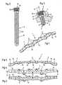
Weitere erfindungsgemäße Merkmale und besondere Vorteile werden in der nachstehendenBeschreibung anhand der Zeichnungen noch näher erläutert. Es zeigen:
Das in den Zeichnungen dargestellte Implantat für Osteosynthesen besteht aus einer mitmehreren in Längsrichtung aufeinander folgenden Löchern 3 versehenen Platte 1 und meistmehreren durch die Löcher 3 in der Platte 1 hindurch einsetzbaren und in bestimmungsgemäßerLage in einen Knochen 4 eindrehbaren Schrauben 2. Zumindest ein Großteil der zurAufnahme der Schrauben 2 bestimmten Löcher 3 sind bezogen auf eine gedachte Mittelebene5 der Platte 1 alternierend nach außen versetzt angeordnet Die Mittelachsen 6 der Löcher3 schließen mit der gedachten Mittelebene 5 der Platte 1 einen spitzen Winkel W ein.Die Löcher 3 verjüngen sich von der bestimmungsgemäß außen liegenden Oberfläche 7 derPlatte 1 ausgehend konisch. Die Schrauben 2 weisen einen zu den von den Löchern 3 gebifdetenAbschnitten im wesentlichen korrespondierenden, sich konisch zu dem mit einem Gewinde8 versehenen Schaft 9 hin verjüngenden Kopf 10 auf. Die Schraube 2 ist über denKopf 10 kraft- und/oder formschlüssig in den Löchern 3 fixierbar.The implant for osteosynthesis shown in the drawings consists of aa plurality of longitudinally
Die Seitenbegrenzungen 11, 12 der Platte 1 folgen im wesentlichen den versetzten Löchern3 und auch. den Außenkonturen der Löcher 3. Die Platte 1 weist daher über deren Länge inDraufsicht gesehen einen im wesentlichen wellenförmigen Verlauf auf. Ferner ist die Platte 1in deren Längsrichtung gesehen mehrfach verwunden ausgeführt, wobei im Bereich der einzelnenLöcher 3 die Hauptausrichtung quer zur Längserstreckung der Platte 1 jeweils zumindestannähernd rechtwinklig zur Mittelachse 6 des entsprechenden Loches 3 verläuft.The
Die einem Mittelabschnitt 13 der Platte bezogen auf deren Länge nächstliegenden beiden Löcher3 sind derselben Seitenbegrenzung 11 (oder 12) der Platte 1 zugewandt. Der Begriff "Mittelabschnitt" bezeichnet zwar einen zentralen Teil der Platte, der die Mitte der Platte enthält, jedoch muss dieser Mittelabschnitt 13 nicht immer genau in der Mitte bezogen auf die Länge der Platte 1 angeordnetsein. Bei Platten mit einer geraden Anzahl von Löchern 3 ist es wohl immer dieMitte (außer bei extrem langen Platten). Bei einer ungeraden Anzahl von Löchern 3 liegt derMittelabschnitt 13 zwischen den Löchern x/2+0,5 und x/2-0,5. Vorteilhaft ist dabei die Konstruktionso, dass die gedachte Mittelebene 5 der Platte 1 auch die Mittelebene 5 des Mittelabschnittes13 der Platte 1 ist.The one
Von der Seite her gesehen ist die Platte 1 leicht gebogen ausgeführt, wobei beispielsweiseder Abstand einer durch die Plattenenden 14 gelegten Sehne vom Mittelabschnitt 13 etwa2 mm betragen kann. Diese Längsbiegung kann auch dem Aufbiegen einer Fraktur entgegenwirken,wenn ein Biegemoment senkrecht auf die Unterseite der Platte einwirkt. Es istdurch diese Längsbiegung eine bessere Anpassung an die Geometrie des Unterarmknochensmöglich geworden.Seen from the side, the
Die Größe der Querschnittsfläche der Platte 1 ist zumindest annähernd über deren ganzeLänge konstant. Die Querschnittsfläche der Platte 1 im Bereich des Mittelabschnittes 13kann jedoch größer ausgeführt sein als in den anderen Abschnitten der Platte 1. Gerade Indiesem den Frakturbereich übergreifenden Mittelabschnitt ist somit eine zusätzliche Optimlerungder Torsionssteifigkeit möglich.The size of the cross-sectional area of the
Der Abstand der Löcher 3 in Längsrichtung der Platte 1 gesehen von den Plattenenden 14ausgehend ist gleichbleibend. Es kann jedoch der Abstand zwischen den beiden an denMittelabschnitt 13 anschließenden Löchern 3 größer sein. Je nach Einsatzbereich oder besondererUmstände ist es auch denkbar, die Lochabstände variabel zu gestalten.The distance of the
An der Unterseite 16 der Platte 1 können ein- oder beidseitig eines jeden Loches 3 nahe derSeitenbegrenzungen 11, 12 auskragende Nocken 17 ausgebildet sein. Diese Nocken 17können bei der Montage der Platte vorteilhaft sein, um dadurch einen entsprechenden Spaltzwischen der Knochenoberfläche und der Platte 1 herzustellen. Im Endzustand wird jedochdie Platte 1 nicht gegen die Oberfläche des Knochens 4 gepresst, so dass die Nocken ohneDruck aufliegen und praktisch nur den Abstand bei der Montage selbst sichern. Durch dasEindrehen der Schrauben selbst erfolgt in keiner Weise ein Anpressen der Platte an die Oberflächedes Knochens.At the bottom 16 of the
Die beiden Enden 14 der Platte 1, aber auch alle Kanten und Übergänge, sind flach und abgerundetausgeführt. Die in der Zeichnung noch annähernd zylindrisch dargestellten Ansätze15 sind lediglich aus Herstellungsgründen noch angebrachte Abschnitte, welche jedoch inder Regel schon vor dem endgültigen Einsatz abgetrennt werden.The two ends 14 of the
Um eine optimale Konvergenz der einzudrehenden Schrauben 2 zu erreichen (siehe auchdie Darstellung in Fig. 3) sind die Mittelachsen 6 der Löcher 3 und somit im eingedrehtenZustand der Schrauben 2 auch deren Mittelachsen in einem spitzen Winkel W zu der gedachtenMittelebene 5 der Platte 1 ausgerichtet. Vorteilhaft schließen die Mittelachsen 6 derLöcher 3 mit der gedachten Mittelebene 5 der Platte 1 einen spitzen Winkel W von annähemd15° ein.In order to achieve optimum convergence of the
Die Platte 1 und vorteilhafterweise auch die Schraube 2 sind aus faserverstärkten Thermoplastenhergestellt. Die Fertigung kann in einem Pressverfahren, beispielsweise in einemFließpressverfahren oder in einem Gegentaktfließpressverfahren, erfolgen. Dabei ist die Anisotropieder elastischen Eigenschaften der Platte 1 auf die Elastizität oder Steifigkeit desKnochens 4 einstellbar. Bei der Herstellung der Platte ist die Anisotropie der elastischen Eigenschaftengemäß der Formel E-Modul(längs) : E-Modul(tangential) = 0,3 bis 0,7 einstellbar.Als optimal wird dabei ein Mittelwert von 0,5 angesehen.The
Damit eine ordnungsgemäße Klemmwirkung des Kopfes 10 der Schraube 2 in dem entsprechendenLoch 3 der Platte 1 erzielt werden kann, um also die erforderliche Steifigkeit dieserVerbindung zu bewerkstelligen, wird vorteilhaft der Kopf 10 der Schraube 2 mit einem Gewinde18 versehen. Auf dem an sich in korrespondierender Konstruktion mit dem Loch 3konisch ausgeführten Kopf 10 der Schraube ist in optimaler Weise ein Feingewinde vorgesehen.Bei einer zweigängigen Ausgestaltung des Feingewindes wird eine dem Gewinde 8auf dem Schaft 9 angepasste Gewindesteigung erreicht und außerdem eine feste Klemmwirkungdes Kopfes 10 der Schraube 2 in bezug auf die Platte 1. Wenn außerdem der Kopf 10der Schraube 2 im Bereich des Gewindes 18 mit einer oder mit mehreren Längsrille(n) versehenist, ist eine Möglichkeit zur Aufnahme von Gewebedebris geschaffen. Beim Eindrehender Schraube 2 wird in den letzten paar Umdrehungen plötzlich eine Erhöhung des Drehmomentesbewirkt, wobei dieses höhere Drehmoment durch den gegenseitigen Eingriff derWandung des Loches 3 und des Kopfes 10 der Schraube 2 zustandekommt. Dies bedeuteteine optimale Klemmwirkung zwischen Schraube 2 und Platte 1, wobei es niemals zu einemÜberdrehen des Gewindes 8 im Knochen 4 kommen kann.So that a proper clamping action of the
Um eine weitere Möglichkeit der Verdrehsicherung zu bewerkstelligen, ist die Schraube 2 anihrem mit einem Gewinde 8 versehenen Schaft 9 im Querschnitt unrund, z.B. trilobular, ausgeführt.Solche Querschnittsformen werden in der Regel als "Gleichdick" bezeichnet ImRahmen der Erfindung wäre es denkbar, auch den Bereich des Kopfes 10 der Schraube 2 imQuerschnitt unrund auszuführen. Der Kopf 10 der Schraube 2 ist mit einem Innenwerkzeugangriff 19 versehen, was für dieMontage und auch für die Demontage solcher Schrauben vorteilhaft ist. Eine vorteilhafteAusgestaltung sieht dabei einen Innenwerkzeugangriff 19 mit vier von einer mittigen Öffnungradial nach außen geführten bogenförmigen Ausbuchtungen vor. Auf diese Weise ist einesehr günstige Übertragung des Drehmomentes möglich.To accomplish a further possibility of rotation, the
Die Schnittdarsteltungen in den Fig. 8 bis 15 bedürfen keiner weiteren Erläuterungen. Dietechnischen Details sind bereits im einzelnen aus der vorstehenden Beschreibung ersichtlich,wobei die Schnittdarstellung für sich selbstredend sind.The Schnittdarsteltungen in Figs. 8 to 15 require no further explanation. Thetechnical details are already apparent in detail from the above description,where the sectional view is self-explanatory.
Sowohl an der Platte 1 als auch an der eingesetzten Schraube 2 sind wesentliche erfinderischeMerkmale gegeben, die in ihrer Summe zusätzlich noch eine optimale Erhöhung derTauglichkeit von Implantaten mit sich bringen.Both on the
Claims (17)
- Implant for osteosyntheses, consisting of a plate (1),which is provided with a plurality of holes (3), whichfollow one another in the longitudinal direction, and screws(2), which can be inserted through the holes (3) in theplate (1) and screwed into a bone in a specified position,wherein at least the majority of the holes (3) intended foraccommodating the screws (2) are staggered outwards in analternating manner relative to an imaginary centre plane (5)of the plate (1), wherein the centre axes (6) of the holes(3) form an acute angle (W) with the imaginary centre plane(5) of the plate (1), wherein the holes (3) taper from thesurface (7) of the plate (1) specified as the outer surface,wherein the holes (3) of the plate (1) taper conically, andwherein the plate (1), viewed in its longitudinal direction,is repeatedly twisted, and the main orientation of the plate(1) in the region of each of the individual holes (3)extends transversely to the longitudinal extent of the plate(1) at a right angle to the centre axis (6) of thecorresponding hole (3),characterised in that the screws (2)comprise a head (10) which corresponds to the portionsformed by the holes (3), tapers conically towards the shank(9), which is provided with a thread (8), and can be fixedby friction type locking and/or positive locking in theholes (3), and that, viewed from the side, the plate (1) isslightly curved, wherein a chord laid through the ends (14)of the plate (1) is at a spacing from the centre portion(13) of the plate (1).
- Implant according to Claim 1,characterised in that thelateral boundaries (11, 12) of the plate (1) follow the staggered holes (3) and the outer contours of the holes (3),so that, viewed over its length in plan view, the plate (1)has a substantially undulatory shape.
- Implant according to Claim 1 or 2,characterised in thatthe two holes (3) which are nearest to the centre portion(13) of the plate (1), related to the length thereof, facethe same lateral boundary (11, 12) of the plate (1).
- Implant according to any one of Claims 1 to 3,characterised in that the imaginary centre plane (5) of theplate (1) is also the centre plane of the centre portion(13) of the plate (1).
- Implant according to any one of Claims 1 to 4,characterised in that the size of the cross-sectional areaof the plate (1) is constant at least approximately over theentire length thereof.
- Implant according to any one of Claims 1 to 4,characterised in that the cross-sectional area of the plate(1) is larger in the region of the centre portion (13) thanin the other portions of the plate (1).
- Implant according to any one of Claims 1 to 6,characterised in that, viewed in the longitudinal directionof the plate (1), starting from the plate ends, the spacingof the holes (3) is uniform, that, however, the spacingbetween the two holes (3) adjacent to the centre portion(13) is greater.
- Implant according to any one of Claims 1 to 7,characterised in that bosses (17), which protrude near thelateral boundaries (11, 12), are formed at the underside(16) of the plate (1) on one or both side(s) of each hole(3) .
- Implant according to any one of Claims 1 to 8,characterised in that the two ends (14) and the edges andtransitions of the plate (1) are flat and rounded.
- Implant according to any one of the preceding Claims,characterised in that the centre axes (6) of the holes (3)form an acute angle (W) of 15E with the imaginary centreplane (5) of the plate (1).
- Implant according to any one of the preceding Claims,characterised in that the plate (1) is made of fibre-reinforcedthermoplastics, and the anisotropy of the elasticproperties of the plate (1) is adapted to the elasticity orstiffness of the bone (4).
- Implant according to Claim 11,characterised in that theanisotropy of the elastic properties of the plate (1) isadapted according to the formula modulus of elasticity(longitudinal) : modulus of elasticity (tangential) = 0.3 to0.7.
- Implant according to any one of the preceding Claims,characterised in that the head (10) of the screw (2) isprovided with a thread (18).
- Implant according to Claim 13,characterised in that thehead (10) of the screw (2) is provided with a fine thread.
- Implant according to Claims 13 and 14,characterised inthat the head (10) of the screw (2) is provided with one ormore longitudinal flute(s) in the region of the thread (18).
- Implant according to any one of the preceding Claims,characterised in that the screw (2) has a non-circular, e.g.trilobular, cross section at its shank (9) provided with athread (8).
- Implant according to any one of the preceding Claims,characterised in that the head (10) of the screw (2) isprovided with an internal tool application part (19) withfour arcuate bulges extending radially outwards from acentral opening.
Applications Claiming Priority (3)
| Application Number | Priority Date | Filing Date | Title |
|---|---|---|---|
| DE19951760ADE19951760B4 (en) | 1999-10-27 | 1999-10-27 | Implant for osteosynthesis |
| DE19951760 | 1999-10-27 | ||
| PCT/EP2000/010465WO2001030251A1 (en) | 1999-10-27 | 2000-10-24 | Implant for osteosyntheses |
Publications (2)
| Publication Number | Publication Date |
|---|---|
| EP1233713A1 EP1233713A1 (en) | 2002-08-28 |
| EP1233713B1true EP1233713B1 (en) | 2004-08-18 |
Family
ID=7927059
Family Applications (1)
| Application Number | Title | Priority Date | Filing Date |
|---|---|---|---|
| EP00972856AExpired - LifetimeEP1233713B1 (en) | 1999-10-27 | 2000-10-24 | Implant for osteosyntheses |
Country Status (8)
| Country | Link |
|---|---|
| US (1) | US6786909B1 (en) |
| EP (1) | EP1233713B1 (en) |
| JP (1) | JP4361709B2 (en) |
| AT (1) | ATE273662T1 (en) |
| AU (1) | AU1144201A (en) |
| CA (1) | CA2388854C (en) |
| DE (2) | DE19951760B4 (en) |
| WO (1) | WO2001030251A1 (en) |
Families Citing this family (56)
| Publication number | Priority date | Publication date | Assignee | Title |
|---|---|---|---|---|
| DE19951760B4 (en) | 1999-10-27 | 2005-06-09 | Sepitec Foundation | Implant for osteosynthesis |
| ATE274857T1 (en)* | 1999-12-06 | 2004-09-15 | Synthes Ag | ABSORBABLE BONE PLATE |
| US7717945B2 (en) | 2002-07-22 | 2010-05-18 | Acumed Llc | Orthopedic systems |
| US20050240187A1 (en) | 2004-04-22 | 2005-10-27 | Huebner Randall J | Expanded fixation of bones |
| AR038680A1 (en) | 2002-02-19 | 2005-01-26 | Synthes Ag | INTERVERTEBRAL IMPLANT |
| CA2515247C (en)* | 2003-02-06 | 2010-10-05 | Synthes (U.S.A.) | Intervertebral implant |
| US7819903B2 (en) | 2003-03-31 | 2010-10-26 | Depuy Spine, Inc. | Spinal fixation plate |
| WO2004112587A2 (en)* | 2003-06-20 | 2004-12-29 | Acumed Llc | Bone plates with intraoperatively tapped apertures |
| JP5170807B2 (en)* | 2003-08-08 | 2013-03-27 | ジンテーズ ゲゼルシャフト ミト ベシュレンクテル ハフツング | Tightening device |
| US7131860B2 (en) | 2003-11-20 | 2006-11-07 | Sherwood Services Ag | Connector systems for electrosurgical generator |
| US20050131407A1 (en)* | 2003-12-16 | 2005-06-16 | Sicvol Christopher W. | Flexible spinal fixation elements |
| US7942913B2 (en) | 2004-04-08 | 2011-05-17 | Ebi, Llc | Bone fixation device |
| US7527640B2 (en) | 2004-12-22 | 2009-05-05 | Ebi, Llc | Bone fixation system |
| WO2006099766A1 (en)* | 2005-03-24 | 2006-09-28 | Medartis Ag | Bone plate |
| US7955364B2 (en) | 2005-09-21 | 2011-06-07 | Ebi, Llc | Variable angle bone fixation assembly |
| KR101246113B1 (en)* | 2005-10-25 | 2013-03-20 | 앤썸 오르소패딕스, 엘엘씨 | Bone fastening assembly and bushing and screw for use therewith |
| US8551145B2 (en)* | 2005-12-19 | 2013-10-08 | Mayo Foundation For Medical Education And Research | Anterior adherent thoracolumbar spine plate |
| US8100952B2 (en)* | 2005-12-22 | 2012-01-24 | Anthem Orthopaedics Llc | Drug delivering bone plate and method and targeting device for use therewith |
| EP1988855A2 (en) | 2006-02-27 | 2008-11-12 | Synthes GmbH | Intervertebral implant with fixation geometry |
| US7780685B2 (en)* | 2006-11-09 | 2010-08-24 | Ethicon Endo-Surgery, Inc. | Adhesive and mechanical fastener |
| DE202006019220U1 (en) | 2006-12-19 | 2007-05-24 | Zrinski Ag | Orthopedic screw fastening system for fixing at bone of patient, has through-holes cut on one another so that intersection line and surfaces are produced in direction of plate thickness, where line and surfaces co-operate with head windings |
| US8142432B2 (en)* | 2007-02-05 | 2012-03-27 | Synthes Usa, Llc | Apparatus for repositioning portions of fractured bone and method of using same |
| US9072548B2 (en)* | 2007-06-07 | 2015-07-07 | Anthem Orthopaedics Llc | Spine repair assembly |
| JP2011502708A (en) | 2007-11-16 | 2011-01-27 | ジンテス ゲゼルシャフト ミット ベシュレンクテル ハフツング | Low profile intervertebral implant |
| WO2009099963A2 (en)* | 2008-01-31 | 2009-08-13 | Cayenne Medical, Inc | Self-tapping biocompatible interference bone screw |
| US9107712B2 (en) | 2008-09-15 | 2015-08-18 | Biomet C.V. | Bone plate system for hand fractures and other small bones |
| CN102256570B (en) | 2008-11-07 | 2015-09-02 | 斯恩蒂斯有限公司 | Spacer and connecting plate assembly between vertebral bodies |
| US8728133B2 (en) | 2009-06-30 | 2014-05-20 | The Penn State Research Foundation | Bone repair system and method |
| US8808333B2 (en) | 2009-07-06 | 2014-08-19 | Zimmer Gmbh | Periprosthetic bone plates |
| US8834532B2 (en)* | 2009-07-07 | 2014-09-16 | Zimmer Gmbh | Plate for the treatment of bone fractures |
| SM200900081B (en)* | 2009-10-05 | 2010-11-12 | Hit Medica S P A | Plate system for osteosynthesis with angular stability multi-axial screws in polymeric material. |
| US20110218580A1 (en)* | 2010-03-08 | 2011-09-08 | Stryker Trauma Sa | Bone fixation system with curved profile threads |
| WO2012088238A2 (en) | 2010-12-21 | 2012-06-28 | Synthes Usa, Llc | Intervertebral implants, systems, and methods of use |
| US9241809B2 (en) | 2010-12-21 | 2016-01-26 | DePuy Synthes Products, Inc. | Intervertebral implants, systems, and methods of use |
| JP2014525776A (en) | 2011-06-30 | 2014-10-02 | ロリオ,モーガン,パッカード | Spine plate and method of using the same |
| US8632574B2 (en)* | 2011-12-07 | 2014-01-21 | Biomet C.V. | Reduced component bone plating system |
| US8790378B2 (en) | 2012-02-02 | 2014-07-29 | Biomet C.V. | Distal radius fracture fixation plate with integrated and adjustable volar ulnar facet support |
| WO2013173873A1 (en)* | 2012-05-22 | 2013-11-28 | Austofix Group Limited | Bone fixation device |
| US20150238233A1 (en)* | 2012-08-09 | 2015-08-27 | Trinity Orthopedics, Llc | Intervertebral Plate Systems and Methods of Use |
| US10231767B2 (en)* | 2013-03-15 | 2019-03-19 | The Penn State Research Foundation | Bone repair system, kit and method |
| US9510880B2 (en)* | 2013-08-13 | 2016-12-06 | Zimmer, Inc. | Polyaxial locking mechanism |
| US9987061B2 (en)* | 2014-01-28 | 2018-06-05 | Biomet C.V. | Implant with suspended locking holes |
| JP6735529B2 (en)* | 2014-07-09 | 2020-08-05 | 国立大学法人東海国立大学機構 | Locking plate system for the treatment of distal radius fractures |
| EP3169425B1 (en) | 2014-07-18 | 2022-08-31 | Sartorius Stedim Biotech GmbH | Membrane with increased surface area |
| US9730686B2 (en) | 2014-09-03 | 2017-08-15 | Biomet C.V. | System and method of soft tissue anchoring to metaphyseal bone plate |
| US9763705B2 (en)* | 2014-10-03 | 2017-09-19 | Globus Medical, Inc. | Orthopedic stabilization devices and methods for installation thereof |
| US9867718B2 (en) | 2014-10-22 | 2018-01-16 | DePuy Synthes Products, Inc. | Intervertebral implants, systems, and methods of use |
| US10245088B2 (en) | 2015-01-07 | 2019-04-02 | Treace Medical Concepts, Inc. | Bone plating system and method |
| WO2016134160A1 (en) | 2015-02-18 | 2016-08-25 | Treace Medical Concepts, Inc. | Bone plating kit for foot and ankle applications |
| US10058363B2 (en)* | 2015-09-07 | 2018-08-28 | Karl Leibinger Medizintechnik Gmbh & Co Kg | Rib fixation system |
| EP3178423B1 (en)* | 2015-12-10 | 2018-02-21 | Stryker European Holdings I, LLC | Bone plate with polyaxial locking mechanism |
| US10357293B2 (en)* | 2016-02-02 | 2019-07-23 | Stryker European Holdings I, Llc | Bone plate with alternating chamfers |
| US11583323B2 (en) | 2018-07-12 | 2023-02-21 | Treace Medical Concepts, Inc. | Multi-diameter bone pin for installing and aligning bone fixation plate while minimizing bone damage |
| JP2019055232A (en)* | 2018-11-27 | 2019-04-11 | 国立大学法人名古屋大学 | Rocking plate system for treatment of radius distal end fracture |
| EP3747384B1 (en) | 2019-06-03 | 2022-12-14 | Stryker European Holdings I, LLC | Rib plate and rib plate system |
| US11890039B1 (en) | 2019-09-13 | 2024-02-06 | Treace Medical Concepts, Inc. | Multi-diameter K-wire for orthopedic applications |
Family Cites Families (14)
| Publication number | Priority date | Publication date | Assignee | Title |
|---|---|---|---|---|
| FR742618A (en) | 1933-03-10 | |||
| CH613858A5 (en)* | 1977-04-22 | 1979-10-31 | Straumann Inst Ag | |
| GB8515870D0 (en)* | 1985-06-22 | 1985-07-24 | Showell A W Sugicraft Ltd | Bone fixation plates |
| US4776330A (en)* | 1986-06-23 | 1988-10-11 | Pfizer Hospital Products Group, Inc. | Modular femoral fixation system |
| DE8628766U1 (en)* | 1986-10-25 | 1986-12-11 | Mecron Medizinische Produkte Gmbh, 1000 Berlin | Bone plate |
| MX170527B (en)* | 1987-11-03 | 1993-08-30 | Synthes Ag | IMPLEMENTATION FOR OSTEOSYNTHESIS |
| JPH066810Y2 (en)* | 1989-11-29 | 1994-02-23 | 旭光学工業株式会社 | Vertebral body fixation plate |
| DE69320593T2 (en)* | 1992-11-25 | 1999-03-04 | Codman & Shurtleff, Inc., Randolph, Mass. | Bone plate system |
| ATE188363T1 (en)* | 1994-02-21 | 2000-01-15 | Collux Ab | IMPLANT FOR THE TREATMENT OF FRACTURES OF THE FEMUR |
| CZ295860B6 (en)* | 1994-12-19 | 2005-11-16 | Sepitec Foundation | Process for producing structural components made of fiber-reinforced thermoplastic materials and structural components produced by this process |
| DE59509247D1 (en) | 1995-09-06 | 2001-06-13 | Synthes Ag | BONE PLATE |
| US5647712A (en)* | 1996-05-09 | 1997-07-15 | Fleetguard, Inc. | One directional socket-driven component |
| US6454769B2 (en)* | 1997-08-04 | 2002-09-24 | Spinal Concepts, Inc. | System and method for stabilizing the human spine with a bone plate |
| DE19951760B4 (en) | 1999-10-27 | 2005-06-09 | Sepitec Foundation | Implant for osteosynthesis |
- 1999
- 1999-10-27DEDE19951760Apatent/DE19951760B4/ennot_activeExpired - Fee Related
- 2000
- 2000-10-24CACA002388854Apatent/CA2388854C/ennot_activeExpired - Fee Related
- 2000-10-24EPEP00972856Apatent/EP1233713B1/ennot_activeExpired - Lifetime
- 2000-10-24AUAU11442/01Apatent/AU1144201A/ennot_activeAbandoned
- 2000-10-24USUS10/111,224patent/US6786909B1/ennot_activeExpired - Lifetime
- 2000-10-24ATAT00972856Tpatent/ATE273662T1/enactive
- 2000-10-24WOPCT/EP2000/010465patent/WO2001030251A1/enactiveIP Right Grant
- 2000-10-24JPJP2001532674Apatent/JP4361709B2/ennot_activeExpired - Fee Related
- 2000-10-24DEDE50007518Tpatent/DE50007518D1/ennot_activeExpired - Lifetime
Also Published As
| Publication number | Publication date |
|---|---|
| WO2001030251A1 (en) | 2001-05-03 |
| US6786909B1 (en) | 2004-09-07 |
| DE19951760A1 (en) | 2001-06-28 |
| DE50007518D1 (en) | 2004-09-23 |
| JP4361709B2 (en) | 2009-11-11 |
| JP2003512125A (en) | 2003-04-02 |
| AU1144201A (en) | 2001-05-08 |
| DE19951760B4 (en) | 2005-06-09 |
| EP1233713A1 (en) | 2002-08-28 |
| CA2388854C (en) | 2008-07-29 |
| ATE273662T1 (en) | 2004-09-15 |
| CA2388854A1 (en) | 2001-05-03 |
Similar Documents
| Publication | Publication Date | Title |
|---|---|---|
| EP1233713B1 (en) | Implant for osteosyntheses | |
| EP1175181B1 (en) | Blockable bone plate | |
| EP1865862B1 (en) | Pedicle screw | |
| EP1608278B1 (en) | Housing for a locking element and locking element | |
| DE4343117C2 (en) | Bone fixation system | |
| EP1613227B1 (en) | Osteosynthesis plate for operative care of bone fractures | |
| EP1389963B1 (en) | Bone plate for the fixation of fractures of the proximal humerus | |
| EP1246578B1 (en) | Bone screw | |
| EP1545357B1 (en) | System for osteosynthesis | |
| EP1622527B1 (en) | Implant comprising a fixing body for a bone screw | |
| WO2005044122A1 (en) | Plate used to stabilise distal radius fractures | |
| EP2844169B1 (en) | Bone plate system for osteosynthesis | |
| EP1133263A1 (en) | Screw | |
| WO2007048267A1 (en) | Thread-forming screw | |
| DE9321544U1 (en) | Osteosynthetic plate | |
| CH695478A5 (en) | Threaded bolt, and Pedrikelschraube Pedrikelschraube with threaded bolt | |
| EP1096891B1 (en) | Osteosynthesis screw | |
| DE102005004841B4 (en) | Osteosynthesis plate with a variety of holes for receiving bone screws | |
| EP0903113A2 (en) | Fixed-angle screw connection for bone plates | |
| WO2001082809A1 (en) | Contoured bone plate | |
| DE202007002190U1 (en) | Part cylindrical Hallux-Valgus bone plate has through holes for bone screws on different angle axes and cylindrical curvature varying in longitudinal direction | |
| EP0589235B1 (en) | Intramedullary nail with locking pin | |
| DE10320124B3 (en) | Osteosynthesis plate, especially an angle-stable radius plate, for the surgical treatment of bone fractures | |
| DE9004717U1 (en) | Osteosynthesis plate | |
| AT508196B1 (en) | FIXING SYSTEM FOR BONE WITH CONVEX DRILLING |
Legal Events
| Date | Code | Title | Description |
|---|---|---|---|
| PUAI | Public reference made under article 153(3) epc to a published international application that has entered the european phase | Free format text:ORIGINAL CODE: 0009012 | |
| 17P | Request for examination filed | Effective date:20020522 | |
| AK | Designated contracting states | Kind code of ref document:A1 Designated state(s):AT BE CH CY DE DK ES FI FR GB GR IE IT LI LU MC NL PT SE | |
| AX | Request for extension of the european patent | Free format text:AL PAYMENT 20020522;LT PAYMENT 20020522;LV PAYMENT 20020522;MK PAYMENT 20020522;RO PAYMENT 20020522;SI PAYMENT 20020522 | |
| GRAP | Despatch of communication of intention to grant a patent | Free format text:ORIGINAL CODE: EPIDOSNIGR1 | |
| GRAS | Grant fee paid | Free format text:ORIGINAL CODE: EPIDOSNIGR3 | |
| GRAA | (expected) grant | Free format text:ORIGINAL CODE: 0009210 | |
| AK | Designated contracting states | Kind code of ref document:B1 Designated state(s):AT BE CH CY DE DK ES FI FR GB GR IE IT LI LU MC NL PT SE | |
| AX | Request for extension of the european patent | Extension state:AL LT LV MK RO SI | |
| PG25 | Lapsed in a contracting state [announced via postgrant information from national office to epo] | Ref country code:IE Free format text:LAPSE BECAUSE OF FAILURE TO SUBMIT A TRANSLATION OF THE DESCRIPTION OR TO PAY THE FEE WITHIN THE PRESCRIBED TIME-LIMIT Effective date:20040818 Ref country code:CY Free format text:LAPSE BECAUSE OF FAILURE TO SUBMIT A TRANSLATION OF THE DESCRIPTION OR TO PAY THE FEE WITHIN THE PRESCRIBED TIME-LIMIT Effective date:20040818 Ref country code:ES Free format text:LAPSE BECAUSE OF FAILURE TO SUBMIT A TRANSLATION OF THE DESCRIPTION OR TO PAY THE FEE WITHIN THE PRESCRIBED TIME-LIMIT Effective date:20040818 | |
| REG | Reference to a national code | Ref country code:GB Ref legal event code:FG4D Free format text:NOT ENGLISH | |
| REG | Reference to a national code | Ref country code:CH Ref legal event code:EP | |
| REG | Reference to a national code | Ref country code:IE Ref legal event code:FG4D Free format text:GERMAN | |
| REF | Corresponds to: | Ref document number:50007518 Country of ref document:DE Date of ref document:20040923 Kind code of ref document:P | |
| PG25 | Lapsed in a contracting state [announced via postgrant information from national office to epo] | Ref country code:LU Free format text:LAPSE BECAUSE OF NON-PAYMENT OF DUE FEES Effective date:20041024 | |
| REG | Reference to a national code | Ref country code:CH Ref legal event code:NV Representative=s name:RIEDERER HASLER & PARTNER PATENTANWAELTE AG | |
| PG25 | Lapsed in a contracting state [announced via postgrant information from national office to epo] | Ref country code:BE Free format text:LAPSE BECAUSE OF NON-PAYMENT OF DUE FEES Effective date:20041031 Ref country code:MC Free format text:LAPSE BECAUSE OF NON-PAYMENT OF DUE FEES Effective date:20041031 | |
| PG25 | Lapsed in a contracting state [announced via postgrant information from national office to epo] | Ref country code:GR Free format text:LAPSE BECAUSE OF FAILURE TO SUBMIT A TRANSLATION OF THE DESCRIPTION OR TO PAY THE FEE WITHIN THE PRESCRIBED TIME-LIMIT Effective date:20041118 Ref country code:DK Free format text:LAPSE BECAUSE OF FAILURE TO SUBMIT A TRANSLATION OF THE DESCRIPTION OR TO PAY THE FEE WITHIN THE PRESCRIBED TIME-LIMIT Effective date:20041118 | |
| REG | Reference to a national code | Ref country code:SE Ref legal event code:TRGR | |
| GBT | Gb: translation of ep patent filed (gb section 77(6)(a)/1977) | Effective date:20041208 | |
| LTIE | Lt: invalidation of european patent or patent extension | Effective date:20040818 | |
| REG | Reference to a national code | Ref country code:IE Ref legal event code:FD4D | |
| BERE | Be: lapsed | Owner name:SEPITEC FOUNDATION Effective date:20041031 | |
| PLBE | No opposition filed within time limit | Free format text:ORIGINAL CODE: 0009261 | |
| STAA | Information on the status of an ep patent application or granted ep patent | Free format text:STATUS: NO OPPOSITION FILED WITHIN TIME LIMIT | |
| ET | Fr: translation filed | ||
| 26N | No opposition filed | Effective date:20050519 | |
| BERE | Be: lapsed | Owner name:*SEPITEC FOUNDATION Effective date:20041031 | |
| PG25 | Lapsed in a contracting state [announced via postgrant information from national office to epo] | Ref country code:PT Free format text:LAPSE BECAUSE OF NON-PAYMENT OF DUE FEES Effective date:20050118 | |
| PGFP | Annual fee paid to national office [announced via postgrant information from national office to epo] | Ref country code:NL Payment date:20081021 Year of fee payment:9 | |
| PGFP | Annual fee paid to national office [announced via postgrant information from national office to epo] | Ref country code:FI Payment date:20081002 Year of fee payment:9 | |
| PGFP | Annual fee paid to national office [announced via postgrant information from national office to epo] | Ref country code:IT Payment date:20081027 Year of fee payment:9 Ref country code:SE Payment date:20081014 Year of fee payment:9 | |
| REG | Reference to a national code | Ref country code:NL Ref legal event code:V1 Effective date:20100501 | |
| EUG | Se: european patent has lapsed | ||
| PG25 | Lapsed in a contracting state [announced via postgrant information from national office to epo] | Ref country code:NL Free format text:LAPSE BECAUSE OF NON-PAYMENT OF DUE FEES Effective date:20100501 | |
| PG25 | Lapsed in a contracting state [announced via postgrant information from national office to epo] | Ref country code:FI Free format text:LAPSE BECAUSE OF NON-PAYMENT OF DUE FEES Effective date:20091024 | |
| PG25 | Lapsed in a contracting state [announced via postgrant information from national office to epo] | Ref country code:IT Free format text:LAPSE BECAUSE OF NON-PAYMENT OF DUE FEES Effective date:20091024 | |
| PG25 | Lapsed in a contracting state [announced via postgrant information from national office to epo] | Ref country code:SE Free format text:LAPSE BECAUSE OF NON-PAYMENT OF DUE FEES Effective date:20091025 | |
| REG | Reference to a national code | Ref country code:DE Ref legal event code:R082 Ref document number:50007518 Country of ref document:DE Representative=s name:SCHUMACHER & WILLSAU PATENTANWALTSGESELLSCHAFT, DE | |
| REG | Reference to a national code | Ref country code:FR Ref legal event code:PLFP Year of fee payment:16 | |
| REG | Reference to a national code | Ref country code:CH Ref legal event code:NV Representative=s name:ISLER AND PEDRAZZINI AG, CH | |
| REG | Reference to a national code | Ref country code:FR Ref legal event code:PLFP Year of fee payment:17 | |
| REG | Reference to a national code | Ref country code:FR Ref legal event code:PLFP Year of fee payment:18 | |
| PGFP | Annual fee paid to national office [announced via postgrant information from national office to epo] | Ref country code:DE Payment date:20171019 Year of fee payment:18 Ref country code:FR Payment date:20171024 Year of fee payment:18 | |
| PGFP | Annual fee paid to national office [announced via postgrant information from national office to epo] | Ref country code:GB Payment date:20171019 Year of fee payment:18 Ref country code:CH Payment date:20171011 Year of fee payment:18 Ref country code:AT Payment date:20171020 Year of fee payment:18 | |
| REG | Reference to a national code | Ref country code:DE Ref legal event code:R119 Ref document number:50007518 Country of ref document:DE | |
| REG | Reference to a national code | Ref country code:CH Ref legal event code:PL | |
| REG | Reference to a national code | Ref country code:AT Ref legal event code:MM01 Ref document number:273662 Country of ref document:AT Kind code of ref document:T Effective date:20181024 | |
| GBPC | Gb: european patent ceased through non-payment of renewal fee | Effective date:20181024 | |
| PG25 | Lapsed in a contracting state [announced via postgrant information from national office to epo] | Ref country code:DE Free format text:LAPSE BECAUSE OF NON-PAYMENT OF DUE FEES Effective date:20190501 | |
| PG25 | Lapsed in a contracting state [announced via postgrant information from national office to epo] | Ref country code:CH Free format text:LAPSE BECAUSE OF NON-PAYMENT OF DUE FEES Effective date:20181031 Ref country code:FR Free format text:LAPSE BECAUSE OF NON-PAYMENT OF DUE FEES Effective date:20181031 Ref country code:LI Free format text:LAPSE BECAUSE OF NON-PAYMENT OF DUE FEES Effective date:20181031 | |
| PG25 | Lapsed in a contracting state [announced via postgrant information from national office to epo] | Ref country code:AT Free format text:LAPSE BECAUSE OF NON-PAYMENT OF DUE FEES Effective date:20181024 Ref country code:GB Free format text:LAPSE BECAUSE OF NON-PAYMENT OF DUE FEES Effective date:20181024 |