EP1233710B1 - Connecting assembly for spinal osteosynthesis - Google Patents
Connecting assembly for spinal osteosynthesisDownload PDFInfo
- Publication number
- EP1233710B1 EP1233710B1EP00985387AEP00985387AEP1233710B1EP 1233710 B1EP1233710 B1EP 1233710B1EP 00985387 AEP00985387 AEP 00985387AEP 00985387 AEP00985387 AEP 00985387AEP 1233710 B1EP1233710 B1EP 1233710B1
- Authority
- EP
- European Patent Office
- Prior art keywords
- connection
- connector
- connection assembly
- osteosynthesis according
- assembly
- Prior art date
- Legal status (The legal status is an assumption and is not a legal conclusion. Google has not performed a legal analysis and makes no representation as to the accuracy of the status listed.)
- Expired - Lifetime
Links
- 210000000988bone and boneAnatomy0.000claimsabstractdescription26
- 230000000903blocking effectEffects0.000claimsdescription14
- 230000035515penetrationEffects0.000claimsdescription5
- 230000000295complement effectEffects0.000claimsdescription4
- 238000006073displacement reactionMethods0.000claimsdescription2
- 230000037431insertionEffects0.000claims1
- 238000003780insertionMethods0.000claims1
- 238000004873anchoringMethods0.000abstractdescription9
- 238000013519translationMethods0.000description6
- 230000014616translationEffects0.000description6
- 210000002445nippleAnatomy0.000description2
- 230000007704transitionEffects0.000description2
- 208000007103SpondylolisthesisDiseases0.000description1
- 238000000926separation methodMethods0.000description1
Images


Classifications
- A—HUMAN NECESSITIES
- A61—MEDICAL OR VETERINARY SCIENCE; HYGIENE
- A61B—DIAGNOSIS; SURGERY; IDENTIFICATION
- A61B17/00—Surgical instruments, devices or methods
- A61B17/56—Surgical instruments or methods for treatment of bones or joints; Devices specially adapted therefor
- A61B17/58—Surgical instruments or methods for treatment of bones or joints; Devices specially adapted therefor for osteosynthesis, e.g. bone plates, screws or setting implements
- A61B17/68—Internal fixation devices, including fasteners and spinal fixators, even if a part thereof projects from the skin
- A61B17/70—Spinal positioners or stabilisers, e.g. stabilisers comprising fluid filler in an implant
- A61B17/7001—Screws or hooks combined with longitudinal elements which do not contact vertebrae
- A61B17/7035—Screws or hooks, wherein a rod-clamping part and a bone-anchoring part can pivot relative to each other
- A61B17/7037—Screws or hooks, wherein a rod-clamping part and a bone-anchoring part can pivot relative to each other wherein pivoting is blocked when the rod is clamped
- A—HUMAN NECESSITIES
- A61—MEDICAL OR VETERINARY SCIENCE; HYGIENE
- A61B—DIAGNOSIS; SURGERY; IDENTIFICATION
- A61B17/00—Surgical instruments, devices or methods
- A61B17/56—Surgical instruments or methods for treatment of bones or joints; Devices specially adapted therefor
- A61B17/58—Surgical instruments or methods for treatment of bones or joints; Devices specially adapted therefor for osteosynthesis, e.g. bone plates, screws or setting implements
- A61B17/68—Internal fixation devices, including fasteners and spinal fixators, even if a part thereof projects from the skin
- A61B17/70—Spinal positioners or stabilisers, e.g. stabilisers comprising fluid filler in an implant
- A61B17/7001—Screws or hooks combined with longitudinal elements which do not contact vertebrae
- A61B17/7002—Longitudinal elements, e.g. rods
- A61B17/7004—Longitudinal elements, e.g. rods with a cross-section which varies along its length
- A61B17/7007—Parts of the longitudinal elements, e.g. their ends, being specially adapted to fit around the screw or hook heads
- A—HUMAN NECESSITIES
- A61—MEDICAL OR VETERINARY SCIENCE; HYGIENE
- A61B—DIAGNOSIS; SURGERY; IDENTIFICATION
- A61B17/00—Surgical instruments, devices or methods
- A61B17/56—Surgical instruments or methods for treatment of bones or joints; Devices specially adapted therefor
- A61B17/58—Surgical instruments or methods for treatment of bones or joints; Devices specially adapted therefor for osteosynthesis, e.g. bone plates, screws or setting implements
- A61B17/68—Internal fixation devices, including fasteners and spinal fixators, even if a part thereof projects from the skin
- A61B17/70—Spinal positioners or stabilisers, e.g. stabilisers comprising fluid filler in an implant
- A61B17/7001—Screws or hooks combined with longitudinal elements which do not contact vertebrae
- A61B17/7002—Longitudinal elements, e.g. rods
- A61B17/701—Longitudinal elements with a non-circular, e.g. rectangular, cross-section
- A—HUMAN NECESSITIES
- A61—MEDICAL OR VETERINARY SCIENCE; HYGIENE
- A61B—DIAGNOSIS; SURGERY; IDENTIFICATION
- A61B17/00—Surgical instruments, devices or methods
- A61B17/56—Surgical instruments or methods for treatment of bones or joints; Devices specially adapted therefor
- A61B17/58—Surgical instruments or methods for treatment of bones or joints; Devices specially adapted therefor for osteosynthesis, e.g. bone plates, screws or setting implements
- A61B17/68—Internal fixation devices, including fasteners and spinal fixators, even if a part thereof projects from the skin
- A61B17/70—Spinal positioners or stabilisers, e.g. stabilisers comprising fluid filler in an implant
- A61B17/7001—Screws or hooks combined with longitudinal elements which do not contact vertebrae
- A61B17/7041—Screws or hooks combined with longitudinal elements which do not contact vertebrae with single longitudinal rod offset laterally from single row of screws or hooks
- A—HUMAN NECESSITIES
- A61—MEDICAL OR VETERINARY SCIENCE; HYGIENE
- A61B—DIAGNOSIS; SURGERY; IDENTIFICATION
- A61B90/00—Instruments, implements or accessories specially adapted for surgery or diagnosis and not covered by any of the groups A61B1/00 - A61B50/00, e.g. for luxation treatment or for protecting wound edges
- A61B90/03—Automatic limiting or abutting means, e.g. for safety
- A61B2090/037—Automatic limiting or abutting means, e.g. for safety with a frangible part, e.g. by reduced diameter
Definitions
- the present inventionaims at a application in the field of spinal osteosynthesis.
- connection set for spinal osteosynthesiscomprising an anchoring means including bone and a connection zone intended to cooperate with a connection means.
- connection sets of the prior artlies in the fact that they offer little of possibility of movement of the different elements one compared to others.
- the present inventionrelates in its meaning the most general a connection set according to the claim 1.
- connection meansis crimped in the connector so as to secure the two parts while by leaving a rotation of the connection means in the connector.
- the connectorhas a cone input into the connector for the passage of the ancillary for the rotational drive of the connection means.
- the angular displacement of the connector on the connecting meansis about 30 degrees when the ancillary drive in rotation of the means of connection is in place.
- the means of connectionhas slots machined in the spherical portion connecting means so as to create a deformation during the final tightening of the system.
- Said slotsare of longitudinal preference.
- connection meanspreferably comprises also in its lower part a skirt. This skirt is threaded on its lower end to facilitate its penetration into the bone.
- Said bone anchoring meanscomprises preferably in its upper part a part of pre-guiding said connection means to enable a good aligning the connection means with the screw.
- connection meansmay be constituted by a nut.
- the connectorhas at least one slot to receive a link element.
- the connectormay have a location blocking opening into the cavity forming the housing of the spherical shape and in the location receiving the element of link.
- connection assemblycan have a locking cylinder which can be inserted into said locking location.
- This locking cylindercan be replaced by a link element.
- the lockout locationcan also lead also in a substantially perpendicular direction for the introduction of a blocking plug.
- the blocking capmay include a nipple for cooperating with a location formed in said adjusting cylinder.
- the location to receive a link elementcan be oblong in the case of a connector of closed type, or U-shaped opening on one of the faces in the case of an open type connector.
- the connectorcan be provided with two slots for receiving a connecting element formed by a bent rod forming a closed U at its ends and in that the element of bond has a shape-shaped cavity complementary to the shape spherical.
- a threaded part, hexagon-shaped,is preferably arranged at the upper end of the means of connection, to allow to screw a secondary nut.
- the present inventionrelates to a set of connection, illustrated in its basic version Figure 1, for spinal osteosynthesis comprising an anchoring means bone including a connection area (29) for cooperate with a connection means.
- the bone anchoring meansmay be constituted by a screw (1) having at least one bone thread (2).
- the screw (1)further comprises a zone of connection (29) for cooperating with said means for connection.
- the bone type thread (2)has a main function: that of ensuring the inking in the bone. he can possibly have a secondary function: to receive the connection system for a connecting element when the connection zone (29) coincides with the part upper bone thread (2).
- a drive system (5) in rotationis provided on the upper end of the screw (1).
- This systemfor example a hexagon, has two functions: that of allowing the drive in rotation of the screw (1) during the penetration into the bone of it, but also a role of rotational locking during the final tightening of the mechanism for avoid greater penetration of the screw (1) into the bone.
- connection meansmakes it possible to make a stop longitudinally along the screw (1) either directly for the connecting element (3 ') when, for example, it is a bent rod forming a U closed at its ends, either by through a connector (8).
- connection meansmay be constituted by a nut (19).
- including the thread (7) of the nut (19)corresponds to the thread of the connection zone (29); it's up to say, in the version shown in Figures 1, 2 and 3, to the thread bone (2) of the screw (1).
- the nut (19)is screwed on the part not buried in the bone of the screw.
- the nut (19)is in its lower part of form spherical (20).
- This spherical shapeis intended to let free positioning of the nut (19) on the connector (8) where is provided a housing of the same type or on the element of link (3).
- This spherical shape (20)also serves as longitudinal positioning stop with connector (8) or with the connecting element (3).
- the connection meansis set in the connector (8) or in the connecting element (3) so as to secure the two pieces while leaving a rotation of the means of connection to the connector (8) or to the link (3).
- a drive system (21) for example a outer hexagonis also provided on the way to connection above its spherical portion (20) so as to allow its adjustment in height as well as that of connector (8) or connecting element (3 ') along the screw (1).
- a cone (22) input in the connector (8)is provided for the passage of the ancillary for the training in rotation of the means of connection.
- the angular deflection D of the axis A of the connector on the connection meansis in the preferential application of 30 degrees when the ancillary drive in rotation of the connection means is in place, as illustrated in FIG.
- Slots (23)are machined in the part spherical connection means so as to create a deformation during final tightening of the system. This The purpose of deformation is to lock the screw (1) in rotation.
- the slots (23)can be positioned transversally, as shown in Figure 2 or longitudinally, as shown in Figure 4.
- the longitudinal slotsare preferably emerging in the lower part of the form spherical (20). There may be one, two, three, four, five, or more.
- connection meanscomprises in its part lower a skirt (28) also visible in Figure 4, as well as figure 5.
- This skirt (28)makes it possible to have a transition mechanical between the screw (1) and the spherical shape (20). In Indeed, a too straightforward transition would encourage a break in the screw at the base of the spherical shape (20) during efforts dynamic.
- the skirt (28)thus makes it possible to better distribute the embedment stress of the screw in the nut.
- This skirt (28)can be threaded on its end to facilitate its penetration into the bone.
- connection zone (29) of the screw (1)can be arranged in the upper part of the bone thread and have the same threads as the bone threads, as shown in Figure 7, but it may also present a different thread, as illustrated in FIGS. 8 and 9, or do not be threaded, as shown in figure 6.
- connection meanstherefore a smooth inner wall and does not constitute a nut.
- the screw (1)comprises in its upper part a smooth part (30) pre-guiding, so to ensure the correct alignment of the connection means during the setting up the means of connection, especially when is a nut (19).
- This pre-guiding part (30)has a smooth wall, as shown in Figures 6 to 9.
- Sin outer diameteris substantially equivalent to that of the inner diameter of the medium connection to ensure the longest longitudinal guidance Linear possible (without angular slope).
- the smooth part (30) pre-guidingcan also serve as a recall zone (34) in the case of treatment of spondylolisthesis.
- This return zone (34)can also be threaded with the same thread as the bone thread (2), as illustrated in Figure 7, or with a different thread, as illustrated figure 8.
- the screw (1)can also be provided with a slot (31) facilitating the separation of the top of the screw (1) comprising the smooth part (30) of pre-guiding and / or the return zone (34). Under this circular slot (31), a drive system (32) is machined which after breaking becomes the drive system of the screw (1), particularly for the removal of the connection assembly, as shown in Figures 7 to 9.
- the connector (8)is provided with a single location to receive an element of link (3) formed by a rod.
- This locationmay be in oblong shape (24) in the case of a connector (8) of the type closed, in the form of a "U" opening on one of the faces in the case of an open type connector.
- the rodIn the case of a connector (8) of the closed type, the rod must be inserted into this one, while in the case of an open connector, the rod (3) can be inserted on the connector posteriorly or laterally.
- the location (24) for receiving the rod (3)is provided so that the rod (3) can come to bear on the spherical shape (20) of the nut (19), as illustrated figure 3.
- the connector (8)also has a location blocking device (25) for receiving a locking system.
- this locking systemis a nut (26) provided with a drive system (27) for applying a sufficient torque to the good mechanical strength of the whole, as illustrated in FIG.
- said connector (8)has a an advanced locking location (25) in which introduced a locking cylinder (36), said location of blocking (25) also opening in one direction substantially perpendicular for the introduction of a plug locking device (37), as illustrated in FIG.
- said locking plug (37)has a nipple (38) for cooperating with a location in said locking cylinder (36) to prevent the locking cylinder (36) does not disengage from the connector when the assembly is not yet tight, as shown figure 11.
- the locking cylinder (36)can be replaced by a connecting element (3), in order to offer a possibility additional connection, as shown in Figure 12.
- the connector (8)is provided with two slots to receive an element of link (3 ') formed by a bent rod forming a U closed to its ends, as shown in Figure 13 and the element of connection (3 ') has a cavity of complementary shape to the spherical shape (20).
- the stemis curved on itself, so as to form a ring of oblong cross section assimilable to a plaque in the field of osteosynthesis.
- a threaded portion (40), hexagon-shaped,is arranged at the upper end of the nut (19), as illustrated in Figure 14, to allow to screw a nut secondary (41) and tighten the assembly.
- the connector (8)is similar to a washer having a cavity for the passage of the connecting element.
- the fastening meansis crimped on the connector (8), trapping the connecting element (3 '), in order to secure the three pieces while allowing a rotation of the fastening means in the connector (8) and a translation of the connecting element (3 ') in this connector (8).
- Final tighteningis achieved by screwing the nut secondary (41) on the fixing means so as to freeze all degrees of freedom.
- the bone anchoring meanscan also be constituted by a hook (4), as illustrated in FIGS. 16 and 17.
Landscapes
- Health & Medical Sciences (AREA)
- Orthopedic Medicine & Surgery (AREA)
- Life Sciences & Earth Sciences (AREA)
- Neurology (AREA)
- Surgery (AREA)
- Molecular Biology (AREA)
- General Health & Medical Sciences (AREA)
- Biomedical Technology (AREA)
- Heart & Thoracic Surgery (AREA)
- Medical Informatics (AREA)
- Nuclear Medicine, Radiotherapy & Molecular Imaging (AREA)
- Animal Behavior & Ethology (AREA)
- Engineering & Computer Science (AREA)
- Public Health (AREA)
- Veterinary Medicine (AREA)
- Surgical Instruments (AREA)
- Prostheses (AREA)
- Orthopedics, Nursing, And Contraception (AREA)
- Steroid Compounds (AREA)
- Electrophonic Musical Instruments (AREA)
Abstract
Description
Translated fromFrenchLa présente invention a pour objectif uneapplication dans le domaine de l'ostéosynthèse rachidienne.The present invention aims at aapplication in the field of spinal osteosynthesis.
La présente invention se rapporte plusparticulièrement à un ensemble de connexion pourl'ostéosynthèse rachidienne comportant un moyen d'ancrageosseux comprenant et une zone de connexion destinée à coopéreravec un moyen de connexion.The present invention relates moreespecially to a connection set forspinal osteosynthesis comprising an anchoring meansincluding bone and a connection zone intended to cooperatewith a connection means.
L'art antérieur connaít des ensembles de connexionet notamment le modèle d'utilité allemand numéro 92 15 561, montrantles caractéristiques du préambule de la revendication 1.The prior art knows connection setsand in particular the German utility model number 92 15 561, showingthe features of the preamble of
L'inconvénient majeur des ensembles de connexion del'art antérieur réside dans le fait qu'ils n'offrent que peude possibilité de mouvement des différents éléments les unspar rapport aux autres.The major disadvantage of the connection sets ofthe prior art lies in the fact that they offer littleof possibility of movement of the different elements onecompared to others.
La présente invention concerne dans son acceptionla plus générale un ensemble de connexion selon larevendication 1.The present invention relates in its meaningthe most general a connection set according to the
Avantageusement, le moyen de connexion est sertidans le connecteur de façon à solidariser les deux pièces touten laissant une rotation du moyen de connexion dans leconnecteur.Advantageously, the connection means is crimpedin the connector so as to secure the two parts whileby leaving a rotation of the connection means in theconnector.
Selon une variante, le connecteur présente un côned'entrée dans le connecteur pour le passage de l'ancillairepour l'entraínement en rotation du moyen de connexion.According to a variant, the connector has a coneinput into the connector for the passage of the ancillaryfor the rotational drive of the connection means.
De préférence, le débattement angulaire duconnecteur sur le moyen de connexion est de 30 degrés environquand l'ancillaire d'entraínement en rotation du moyen deconnexion est en place.Preferably, the angular displacement of theconnector on the connecting means is about 30 degreeswhen the ancillary drive in rotation of the means ofconnection is in place.
Selon un mode de réalisation préféré, le moyen deconnexion présente des fentes usinées dans la partie sphériquedu moyen de connexion de façon à créer une déformation lors duserrage définitif du système. Lesdites fentes sont depréférence longitudinales.According to a preferred embodiment, the means ofconnection has slots machined in the spherical portionconnecting means so as to create a deformation during thefinal tightening of the system. Said slots are oflongitudinal preference.
Ledit moyen de connexion comporte de préférenceégalement dans sa partie inférieure une jupe. Cette jupe estfiletée sur son extrémité inférieure pour faciliter sapénétration dans l'os.Said connection means preferably comprisesalso in its lower part a skirt. This skirt isthreaded on its lower end to facilitate itspenetration into the bone.
Ledit un moyen d'ancrage osseux comporte depréférence dans sa partie supérieure une partie de pré-guidagedudit moyen de connexion afin de permettre de réaliser un bonalignement du moyen de connexion avec la vis.Said bone anchoring means comprisespreferably in its upper part a part of pre-guidingsaid connection means to enable a goodaligning the connection means with the screw.
Le moyen de connexion peut être constitué par unécrou.The connection means may be constituted by anut.
Le connecteur est pourvu d'au moins un emplacementpour recevoir un élément de liaison.The connector has at least one slotto receive a link element.
Le connecteur peut comporter un emplacement deblocage débouchant dans la cavité formant le logement de laforme sphérique et dans l'emplacement recevant l'élément deliaison.The connector may have a locationblocking opening into the cavity forming the housing of thespherical shape and in the location receiving the element oflink.
L'ensemble de connexion selon l'invention peutcomporter un cylindre de blocage qui peut être introduit dansledit emplacement de blocage. Ce cylindre de blocage peut êtreremplacé par un élément de liaison.The connection assembly according to the invention canhave a locking cylinder which can be inserted intosaid locking location. This locking cylinder can bereplaced by a link element.
L'emplacement de blocage peut en outre déboucherégalement dans une direction sensiblement perpendiculaire pourl'introduction d'un bouchon de blocage. Le bouchon de blocagepeut comporter un téton destiné à coopérer avec un emplacementménagé dans ledit cylindre de réglage.The lockout location can also leadalso in a substantially perpendicular direction forthe introduction of a blocking plug. The blocking capmay include a nipple for cooperating with a locationformed in said adjusting cylinder.
L'emplacement pour recevoir un élément de liaisonpeut être en forme de oblong dans le cas d'un connecteur detype fermé, ou en forme de « U » débouchante sur une des facesdans le cas d'un connecteur de type ouvert.The location to receive a link elementcan be oblong in the case of a connector ofclosed type, or U-shaped opening on one of the facesin the case of an open type connector.
Le connecteur peut être pourvu de deux emplacementspour recevoir un élément de liaison formé par une tige coudéeformant un U fermé à ses extrémités et en ce que l'élément deliaison présente une cavité de forme complémentaire à la formesphérique.The connector can be provided with two slotsfor receiving a connecting element formed by a bent rodforming a closed U at its ends and in that the element ofbond has a shape-shaped cavity complementary to the shapespherical.
Une partie filetée, en forme d'hexagone, est depréférence aménagée à l'extrémité supérieure du moyen deconnexion, afin de permettre de visser un écrou secondaire.A threaded part, hexagon-shaped, ispreferably arranged at the upper end of the means ofconnection, to allow to screw a secondary nut.
La présente invention sera mieux comprise à lalecture de la description d'un exemple non limitatif deréalisation qui suit, se référant aux dessins annexés où :
- la figure 1 représente une vue en perspectived'un ensemble de connexion dans sa version de base avec unmoyen d'ancrage osseux vis ;
- la figure 2 représente une vue éclatée del'ensemble de connexion de la figure 1 ;
- la figure 3 représente une vue en coupepartielle de l'ensemble de connexion de la figure 1 ;
- la figure 4 représente une vue en perspectived'un écrou selon l'invention avec jupe et fenteslongitudinales ;
- la figure 5 représente une vue partielle enperspective d'un écrou selon la figure 4 monté sur unconnecteur ;
- la figure 6 représente une vue en perspectived'une vis comportant une partie de pré-guidage et/ou unepartie de rappel lisse, ainsi qu'une partie de connexionlisse ;
- la figure 7 représente une vue en perspectived'une vis comportant une partie de pré-guidage lisse, une partie de rappel filetée et une partie de connexion filetéeconfondue avec le filetage osseux ;
- la figure 8 représente une vue en perspectived'une vis comportant une partie de pré-guidage lisse, unepartie de rappel filetée et une partie de connexion filetéenon confondue avec le filetage osseux ;
- la figure 9 représente une vue en perspectived'une vis comportant une partie de pré-guidage lisse et unepartie de connexion filetée non confondue avec le filetageosseux ;
- la figure 10 représente une vue en perspectived'un ensemble de connexion avec un système de blocage entre lemoyen de connexion et la tige de connexion ;
- la figure 11 représente une vue en coupe del'ensemble de connexion de la figure 10 avec un cylindre deblocage ;
- la figure 12 représente une vue en perspectivede l'ensemble de connexion de la figure 10 avec un deuxièmeélément de connexion ;
- la figure 13 représente une vue en perspectived'un ensemble de connexion dans une variante avec une tige deliaison coudée formant un U fermé à ses extrémités ;
- la figure 14 représente une vue éclatée del'ensemble de connexion de la figure 13 ;
- la figure 15 représente une vue partielle encoupe de l'ensemble de connexion de la figure 13 ;
- la figure 16 représente une vue en perspectived'un moyen d'ancrage osseux crochet ; et
- la figure 17 représente une vue en perspectived'un ensemble de connexion avec un moyen d'ancrage osseuxcrochet.
- Figure 1 shows a perspective view of a connection assembly in its basic version with bone anchoring means screws;
- Figure 2 shows an exploded view of the connection assembly of Figure 1;
- Figure 3 shows a partial sectional view of the connection assembly of Figure 1;
- Figure 4 shows a perspective view of a nut according to the invention with skirt and longitudinal slots;
- Figure 5 shows a partial perspective view of a nut according to Figure 4 mounted on a connector;
- Figure 6 shows a perspective view of a screw having a pre-guiding portion and / or a smooth return portion, and a smooth connecting portion;
- Figure 7 shows a perspective view of a screw having a smooth pre-guide portion, a threaded return portion and a threaded connection portion merged with the bone thread;
- Figure 8 shows a perspective view of a screw having a smooth pre-guide portion, a threaded return portion and a threaded connection portion not merged with the bone thread;
- Figure 9 shows a perspective view of a screw having a smooth pre-guide portion and a threaded connection portion not merged with the bone thread;
- Figure 10 shows a perspective view of a connection assembly with a locking system between the connection means and the connecting rod;
- Fig. 11 is a sectional view of the connection assembly of Fig. 10 with a locking cylinder;
- Fig. 12 is a perspective view of the connection assembly of Fig. 10 with a second connecting element;
- Figure 13 shows a perspective view of a connection assembly in an alternative with a bent connecting rod forming a U closed at its ends;
- Fig. 14 is an exploded view of the connection assembly of Fig. 13;
- Figure 15 shows a partial sectional view of the connection assembly of Figure 13;
- Figure 16 shows a perspective view of a hook bone anchoring means; and
- Figure 17 shows a perspective view of a connection assembly with hook bone anchoring means.
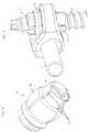
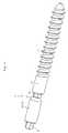
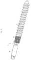
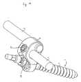
La présente invention se rapporte à un ensemble deconnexion, illustré dans sa version de base figure 1, pour l'ostéosynthèse rachidienne comportant un moyen d'ancrageosseux comprenant une zone de connexion (29) destinée àcoopérer avec un moyen de connexion.The present invention relates to a set ofconnection, illustrated in its basic version Figure 1, forspinal osteosynthesis comprising an anchoring meansbone including a connection area (29) forcooperate with a connection means.
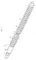
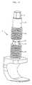
Le moyen d'ancrage osseux peut être constitué parune vis (1) comportant au moins un filetage osseux (2).The bone anchoring means may be constituted bya screw (1) having at least one bone thread (2).
La vis (1) comporte en outre une zone deconnexion (29) destinée à coopérer avec ledit moyen deconnexion.The screw (1) further comprises a zone ofconnection (29) for cooperating with said means forconnection.
Le filetage de type osseux (2) présente unefonction principale : celle d'assurer l'encrage dans l'os. Ilpeut éventuellement présenter une fonction secondaire : cellede recevoir le système de connexion pour un élément de liaisonlorsque la zone de connexion (29) est confondue avec la partiesupérieure du filetage osseux (2).The bone type thread (2) has amain function: that of ensuring the inking in the bone. hecan possibly have a secondary function:to receive the connection system for a connecting elementwhen the connection zone (29) coincides with the partupper bone thread (2).
Sur l'extrémité supérieure de la vis (1), unsystème d'entraínement (5) en rotation est prévu. Ce systèmepar exemple un hexagone, a deux fonctions : Celle de permettrel'entraínement en rotation de la vis (1) lors de lapénétration dans l'os de celle-ci, mais également un rôle deblocage en rotation lors du serrage final du mécanisme pouréviter une pénétration plus importante de la vis (1) dansl'os.On the upper end of the screw (1), adrive system (5) in rotation is provided. This systemfor example a hexagon, has two functions: that of allowingthe drive in rotation of the screw (1) during thepenetration into the bone of it, but also a role ofrotational locking during the final tightening of the mechanism foravoid greater penetration of the screw (1) intothe bone.
Le moyen de connexion permet de réaliser une butéelongitudinale le long de la vis (1) soit directement pourl'élément de liaison (3') lorsque, par exemple, celui-ci estune tige coudée formant un U fermé à ses extrémités, soit parle biais d'un connecteur (8).The connection means makes it possible to make a stoplongitudinally along the screw (1) either directly forthe connecting element (3 ') when, for example, it isa bent rod forming a U closed at its ends, either bythrough a connector (8).
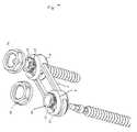
Le moyen de connexion peut être constitué par unécrou (19). Dans ce cas, dont le taraudage (7) de l'écrou (19)correspond au filetage de la zone de connexion (29) ; c'est àdire, dans la version illustrée figures 1, 2 et 3, au filetage osseux (2) de la vis (1). L'écrou (19) est vissé sur la partienon enfouie de l'os de la vis.The connection means may be constituted by anut (19). In this case, including the thread (7) of the nut (19)corresponds to the thread of the connection zone (29); it's up tosay, in the version shown in Figures 1, 2 and 3, to the threadbone (2) of the screw (1). The nut (19) is screwed on the partnot buried in the bone of the screw.
L'écrou (19) est dans sa partie inférieure de formesphérique (20). Cette forme sphérique est destinée à laisserun positionnement libre de l'écrou (19) sur le connecteur (8)où est prévu un logement du même type ou sur l'élément deliaison (3). Cette forme sphérique (20) sert également debutée de positionnement longitudinal avec le connecteur (8) ouavec l'élément de liaison (3). Dans l'applicationpréférentielle, le moyen de connexion est serti dans leconnecteur (8) ou dans l'élément de liaison (3) de façon àsolidariser les deux pièces tout en laissant une rotation dumoyen de connexion sur le connecteur (8) ou sur l'élément deliaison (3).The nut (19) is in its lower part of formspherical (20). This spherical shape is intended to letfree positioning of the nut (19) on the connector (8)where is provided a housing of the same type or on the element oflink (3). This spherical shape (20) also serves aslongitudinal positioning stop with connector (8) orwith the connecting element (3). In the applicationpreferential, the connection means is set in theconnector (8) or in the connecting element (3) so as tosecure the two pieces while leaving a rotation of themeans of connection to the connector (8) or to thelink (3).
Un système d'entraínement (21) par exemple unhexagone extérieur est également prévu sur le moyen deconnexion au-dessus de sa partie sphérique (20) de façon àpermettre son réglage en hauteur ainsi que celui duconnecteur (8) ou de l'élément de liaison (3') le long de lavis (1). En conséquence de la possibilité de rotation duconnecteur sur le moyen de connexion, un cône (22) d'entréedans le connecteur (8) est prévu pour le passage del'ancillaire pour l'entraínement en rotation du moyen deconnexion. A titre d'exemple, le débattement angulaire D del'axe A du connecteur sur le moyen de connexion est dansl'application préférentielle de 30 degrés quand l'ancillaired'entraínement en rotation du moyen de connexion est en place,comme illustré figure 3.A drive system (21) for example aouter hexagon is also provided on the way toconnection above its spherical portion (20) so as toallow its adjustment in height as well as that ofconnector (8) or connecting element (3 ') along thescrew (1). As a consequence of the possibility of rotation of theconnector on the connection means, a cone (22) inputin the connector (8) is provided for the passage ofthe ancillary for the training in rotation of the means ofconnection. For example, the angular deflection D ofthe axis A of the connector on the connection means is inthe preferential application of 30 degrees when the ancillarydrive in rotation of the connection means is in place,as illustrated in FIG.
Des fentes (23) sont usinées dans la partiesphérique du moyen de connexion de façon à créer unedéformation lors du serrage définitif du système. Cettedéformation a pour but de bloquer en rotation la vis (1).Slots (23) are machined in the partspherical connection means so as to create adeformation during final tightening of the system. ThisThe purpose of deformation is to lock the screw (1) in rotation.
Les fentes (23) peuvent être positionnéestransversalement, comme illustré figure 2 oulongitudinalement, comme illustré figure 4.The slots (23) can be positionedtransversally, as shown in Figure 2 orlongitudinally, as shown in Figure 4.
Les fentes longitudinales sont de préférencedébouchantes dans la partie inférieure de la formesphérique (20). Elles peuvent être au nombre de une, deux,trois, quatre, cinq, ou plus.The longitudinal slots are preferablyemerging in the lower part of the formspherical (20). There may be one, two,three, four, five, or more.
Le moyen de connexion comporte dans sa partieinférieure une jupe (28) également visible figure 4, ainsi quefigure 5. Cette jupe (28) permet d'avoir une transitionmécanique entre la vis (1) et la forme sphérique (20). Eneffet, une transition trop franche favoriserait une rupture dela vis à la base de la forme sphérique (20) lors d'effortsdynamiques. La jupe (28) permet ainsi de mieux répartir lacontrainte d'encastrement de la vis dans l'écrou.The connection means comprises in its partlower a skirt (28) also visible in Figure 4, as well asfigure 5. This skirt (28) makes it possible to have a transitionmechanical between the screw (1) and the spherical shape (20). InIndeed, a too straightforward transition would encourage a break inthe screw at the base of the spherical shape (20) during effortsdynamic. The skirt (28) thus makes it possible to better distribute theembedment stress of the screw in the nut.
Cette jupe (28) peut être filetée sur son extrémitépour faciliter sa pénétration dans l'os.This skirt (28) can be threaded on its endto facilitate its penetration into the bone.
La zone de connexion (29) de la vis (1) peut êtreménagée dans la parie supérieure du filetage osseux etprésenter un filetage identique au filetage osseux, commeillustré figure 7, mais elle peut également présenter unfiletage différent, comme illustré figures 8 et 9, ou encorene pas être filetée, comme illustré figure 6.The connection zone (29) of the screw (1) can bearranged in the upper part of the bone thread andhave the same threads as the bone threads, asshown in Figure 7, but it may also present adifferent thread, as illustrated in FIGS. 8 and 9, ordo not be threaded, as shown in figure 6.
Dans ce dernier cas, le moyen de connexion présentepar conséquent une paroi intérieure lisse et ne constitue pasun écrou.In the latter case, the present connection meanstherefore a smooth inner wall and does not constitutea nut.
Dans une variante, la vis (1) comporte dans sapartie supérieure une partie lisse (30) de pré-guidage, afind'assurer le bon alignement du moyen de connexion lors de lamise en place du moyen de connexion, a fortiori lorsqu'ils'agit d'un écrou (19).In a variant, the screw (1) comprises in itsupper part a smooth part (30) pre-guiding, soto ensure the correct alignment of the connection means during thesetting up the means of connection, especially whenis a nut (19).
Cette partie de pré-guidage (30) est à paroi lisse,comme illustré aux figures 6 à 9. Sin diamètre extérieur estsensiblement équivalent à celui du diamètre intérieur du moyende connexion pour assurer un guidage longitudinal le pluslinéaire possible (sans pente angulaire).This pre-guiding part (30) has a smooth wall,as shown in Figures 6 to 9. Sin outer diameter issubstantially equivalent to that of the inner diameter of the mediumconnection to ensure the longest longitudinal guidanceLinear possible (without angular slope).
La partie lisse (30) de pré-guidage peut égalementservir de zone de rappel (34) dans le cas de traitement despondylolisthésis.The smooth part (30) pre-guiding can alsoserve as a recall zone (34) in the case of treatment ofspondylolisthesis.
Cette zone de rappel (34) peut également êtrefiletée avec un filetage identique au filetage osseux (2),comme illustré figure 7, ou avec un filetage différent, commeillustré figure 8.This return zone (34) can also bethreaded with the same thread as the bone thread (2),as illustrated in Figure 7, or with a different thread, asillustrated figure 8.
La vis (1) peut également être munie d'unefente (31) facilitant la désolidarisation du haut de lavis (1) comportant la partie lisse (30) de pré-guidage et/oula zone de rappel (34). Sous cette fente (31) circulaire, unsystème d'entraínement (32) est usiné qui après la rupturedevient le système d'entraínement de la vis (1),particulièrement pour l'ablation de l'ensemble de connexion,comme illustré aux figures 7 à 9.The screw (1) can also be provided with aslot (31) facilitating the separation of the top of thescrew (1) comprising the smooth part (30) of pre-guiding and / orthe return zone (34). Under this circular slot (31), adrive system (32) is machined which after breakingbecomes the drive system of the screw (1),particularly for the removal of the connection assembly,as shown in Figures 7 to 9.
Dans la version de base, le connecteur (8) estpourvu d'un seul emplacement pour recevoir un élément deliaison (3) formé par une tige. Cet emplacement peut être enforme de oblong (24) dans le cas d'un connecteur (8) de typefermé, soit en forme de « U » débouchante sur une des facesdans le cas d'un connecteur de type ouvert. Dans le cas d'unconnecteur (8) de type fermé, la tige doit être enfilée danscelui-ci, tandis que dans le cas d'un connecteur ouvert, latige (3) peut être introduite sur le connecteurpostérieurement ou latéralement.In the basic version, the connector (8) isprovided with a single location to receive an element oflink (3) formed by a rod. This location may be inoblong shape (24) in the case of a connector (8) of the typeclosed, in the form of a "U" opening on one of the facesin the case of an open type connector. In the case of aconnector (8) of the closed type, the rod must be inserted intothis one, while in the case of an open connector, therod (3) can be inserted on the connectorposteriorly or laterally.
L'emplacement (24) de réception de la tige (3) estprévu de manière à ce que la tige (3) puisse venir en appuisur la forme sphérique (20) de l'écrou (19), comme illustréfigure 3.The location (24) for receiving the rod (3) isprovided so that the rod (3) can come to bearon the spherical shape (20) of the nut (19), as illustratedfigure 3.
Il est donc entendu que la tige (3) par rapport àla vis (1) est libre dans trois axes de rotations et dans deuxdirections de translations :
- Rotation du connecteur (8) et donc de latige (3) autour du moyen de fixation dans deux axesperpendiculaires à la vis (1) ;
- Rotation du connecteur (8) et donc de latige (3) autour du moyen de fixation dans un axe identique àcelui de la vis (1) ;
- Translation de la tige (3) dans leconnecteur (8) suivant l'axe de celle-ci ;
- Translation du connecteur (8) et donc de latige (3) le long de la vis (1) grâce à la possibilité deréglage du moyen de fixation.
- Rotation of the connector (8) and therefore of the rod (3) around the fastening means in two axes perpendicular to the screw (1);
- Rotation of the connector (8) and therefore of the rod (3) around the fastening means in an axis identical to that of the screw (1);
- Translation of the rod (3) in the connector (8) along the axis thereof;
- Translation of the connector (8) and thus of the rod (3) along the screw (1) thanks to the possibility of adjustment of the fixing means.
En outre, la rotation de la tige (3) sur elle-mêmepeut offrir un degré de liberté supplémentaire à l'ensemble deconnexion.In addition, the rotation of the rod (3) on itselfcan offer an additional degree of freedom to the entireconnection.
Le connecteur (8) possède également un emplacementde blocage (25) pour recevoir un système de blocage. Dansl'application de base, ce système de blocage est un écrou (26)pourvu d'un système d'entraínement (27) pour appliquer uncouple suffisant à la bonne tenue mécanique de l'ensemble,comme illustré figure 3.The connector (8) also has a locationblocking device (25) for receiving a locking system. Inthe basic application, this locking system is a nut (26)provided with a drive system (27) for applying asufficient torque to the good mechanical strength of the whole,as illustrated in FIG.
Le blocage d'une telle connexion est assurée par lapression de l'élément de liaison (3) sur la formesphérique (20). L'élément de liaison (3) étant solidaire duconnecteur (8) par la pression opérée par l'écrou (26), lesdegrés de liberté sont alors tous figés.The blocking of such a connection is ensured by thepressure of the connecting element (3) on the formspherical (20). The connecting element (3) being integral with theconnector (8) by the pressure operated by the nut (26), thedegrees of freedom are then all frozen.
Dans une variante, ledit connecteur (8) comporte unemplacement de blocage (25) évolué, dans lequel peut êtreintroduit un cylindre de blocage (36), ledit emplacement deblocage (25) débouchant également dans une directionsensiblement perpendiculaire pour l'introduction d'un bouchonde blocage (37), comme illustré figure 10.In a variant, said connector (8) has aan advanced locking location (25) in whichintroduced a locking cylinder (36), said location ofblocking (25) also opening in one directionsubstantially perpendicular for the introduction of a pluglocking device (37), as illustrated in FIG.
En outre, ledit bouchon de blocage (37) comporte untéton (38) destiné à coopérer avec un emplacement ménagé dansledit cylindre de blocage (36), afin d'empêcher que le cylindre de blocage (36) ne se désolidarise du connecteurlorsque l'ensemble n'est pas encore serré, comme illustréfigure 11.In addition, said locking plug (37) has anipple (38) for cooperating with a location insaid locking cylinder (36) to prevent thelocking cylinder (36) does not disengage from the connectorwhen the assembly is not yet tight, as shownfigure 11.
Le cylindre de blocage (36) peut être remplacé parun élément de liaison (3), afin d'offrir une possibilitésupplémentaire de connexion, comme illustré figure 12.The locking cylinder (36) can be replaced bya connecting element (3), in order to offer a possibilityadditional connection, as shown in Figure 12.
Dans cette version, le serrage de l'ensemble estassuré par la force qui est opérée à la fois sur l'élément deliaison (3) et sur la partie sphérique (20) par le cylindre deconnexion (36) ou par le second élément de liaison (3).In this version, the tightening of the whole isassured by the force that is operated on both the element ofconnection (3) and on the spherical part (20) by the cylinder ofconnection (36) or by the second connecting element (3).
Il est nécessaire de prévoir une pluralité deconnecteurs, afin de pouvoir choisir celui dont la distanceentre la vis et l'élément de liaison ou les éléments deliaison est adéquat.It is necessary to provide for a plurality ofconnectors, so you can choose the one whose distancebetween the screw and the connecting element or the elements ofliaison is adequate.
Dans une autre version, le connecteur (8) estpourvu de deux emplacements pour recevoir un élément deliaison (3') formé par une tige coudée formant un U fermé àses extrémités, comme illustré figure 13 et l'élément deliaison (3') présente une cavité de forme complémentaire à laforme sphérique (20).In another version, the connector (8) isprovided with two slots to receive an element oflink (3 ') formed by a bent rod forming a U closed toits ends, as shown in Figure 13 and the element ofconnection (3 ') has a cavity of complementary shape to thespherical shape (20).
La tige est courbée sur elle-même, de façon àformer un anneau de section transversale oblongue assimilableà une plaque dans le domaine de l'ostéosynthèse.The stem is curved on itself, so as toform a ring of oblong cross section assimilableto a plaque in the field of osteosynthesis.
Une partie filetée (40), en forme d'hexagone, estaménagée à l'extrémité supérieure de l'écrou (19), commeillustré figure 14, afin de permettre de visser un écrousecondaire (41) et serrer l'ensemble.A threaded portion (40), hexagon-shaped, isarranged at the upper end of the nut (19), asillustrated in Figure 14, to allow to screw a nutsecondary (41) and tighten the assembly.
Le connecteur (8) est assimilable à une rondelleprésentant une cavité pour le passage de l'élément de liaison.The connector (8) is similar to a washerhaving a cavity for the passage of the connecting element.
Un chanfrein (42), illustré figure 15 est aménagésur l'écrou secondaire (41) ; Ce chanfrein est destiné àcoopérer avec la partie supérieure extérieure duconnecteur (8).A chamfer (42), illustrated in FIG.on the secondary nut (41); This chamfer is intended forcooperate with the outermost part of theconnector (8).
Dans cette version, le moyen de fixation est sertisur le connecteur (8), emprisonnant l'élément de liaison (3'),de façon à solidariser les trois pièces tout en autorisant unerotation du moyen de fixation dans le connecteur (8) et unetranslation de l'élément de liaison (3') dans ceconnecteur (8).In this version, the fastening means is crimpedon the connector (8), trapping the connecting element (3 '),in order to secure the three pieces while allowing arotation of the fastening means in the connector (8) and atranslation of the connecting element (3 ') in thisconnector (8).
Le serrage final est réalisé en vissant l'écrousecondaire (41) sur le moyen de fixation de manière à figerl'ensemble des degrés de liberté.Final tightening is achieved by screwing the nutsecondary (41) on the fixing means so as to freezeall degrees of freedom.
Le moyen d'ancrage osseux peut également êtreconstitué par un crochet (4), comme illustré figures 16 et 17.The bone anchoring means can also beconstituted by a hook (4), as illustrated in FIGS. 16 and 17.
Claims (19)
- Connection assembly for spinal osteosynthesiscomprising an osseous anchor means including a connectionarea (29) designed to cooperate with a connection means,characterised in that the bottom part of the connectionmeans comprises a spherical shape (20) so that aconnection means can be freely positioned in a connector(8) or in a connection element (3'), this spherical shape(20) forming a longitudinal positioning stop with theconnector (8) or with the connection element (3'),characterised in that the said connector (8) orconnection element (3') has a complementary shapedcavity.
- Connection assembly for osteosynthesis according toclaim 1,characterised in that the connection means iscrimped in the connector (8) so as to fix the two partswhile allowing the connection means to rotate in theconnector (8).
- Connection assembly for osteosynthesis according toclaim 1 or 2,characterised in that the connector has aninput cone (22) in the connector (8) to enable anancillary to pass through to drive the connection meansin rotation.
- Connection assembly for osteosynthesis according toclaim 3,characterised in that the angular displacement of the connector (8) on the connection means is about30 degrees when the rotation drive ancillary of theconnection means is in place.
- Connection assembly for osteosynthesis according to atleast one of the previous claims,characterised in thatthe connection means has slits (23) machined in thespherical part (20) of the connection means so as tocreate a deformation during final clamping of the system.
- Connection assembly for osteosynthesis according toclaim 5,characterised in that the said slits (23) arelongitudinal.
- Connection assembly for osteosynthesis according to atleast one of the previous claims,characterised in thatthe bottom part of the said connection means comprises askirt (28).
- Connection assembly for osteosynthesis according toclaim 7,characterised in that the said skirt (28) isthreaded at its lower end to facilitate penetration intothe bone.
- Connection assembly for osteosynthesis according to atleast one of the previous claims,characterised in thatthe top part of the osseous anchor means comprises asmooth pre-guiding part (30) for the said connectionmeans.
- Connection assembly for osteosynthesis according toat least one of the previous claims,characterised inthat the connection means comprises a nut (19).
- Connection assembly for osteosynthesis according toat least one of the previous claims,characterised inthat the connector (8) is provided with at least oneposition (24) to hold a connection element (3, 3').
- Connection assembly for osteosynthesis according toclaim 11,characterised in that the said connector (8)comprises a blocking position (25) opening up in thecavity forming the housing of the spherical shape (20)and in the position (24) into which the connectionelement (3,3') will fit.
- Connection assembly for osteosynthesis according toclaim 12,characterised in that it comprises a blockingcylinder (36) that can be inserted in the said blockingposition (25).
- Connection assembly for osteosynthesis according toclaim 13,characterised in that the said blockingcylinder (36) may be replaced by a connection element(3).
- Connection assembly for osteosynthesis according toclaim 13 or claim 14,characterised in that the said blocking position (25) also opens up in an approximatelyperpendicular direction for insertion of a blocking plug(37).
- Connection assembly for osteosynthesis according toclaim 15,characterised in that the said blocking plug(37) comprises a pin (38) that will cooperate with aposition formed in the said blocking cylinder (36).
- Connection assembly for osteosynthesis according toany one of claims 11 to 16,characterised in that thesaid position (24) is in the form of an oblong in thecase of a closed type connector (8), or in the form of a"U" opening up on one of the faces in the case of an opentype connector.
- Connection assembly for osteosynthesis according toclaim 11,characterised in that the connector (8) isprovided with two positions (24) to contain a connectionelement (3') formed by a cranked rod forming a U closedat its ends andin that the shape of the connectionelement (3') is complementary to the spherical shape(20).
- Connection assembly for osteosynthesis according toat least one of the previous claims,characterised inthat a hexagonal shaped threaded part (40) is formed atthe top end of the connection means, so that a secondarynut (41) can be screwed in.
Applications Claiming Priority (3)
| Application Number | Priority Date | Filing Date | Title |
|---|---|---|---|
| FR9915295AFR2801778B1 (en) | 1999-12-03 | 1999-12-03 | CONNECTION ASSEMBLY FOR THE FIELD OF RACHIDIAN OSTEOSYNTHESIS |
| FR9915295 | 1999-12-03 | ||
| PCT/FR2000/003365WO2001039677A1 (en) | 1999-12-03 | 2000-12-01 | Connecting assembly for spinal osteosynthesis |
Publications (2)
| Publication Number | Publication Date |
|---|---|
| EP1233710A1 EP1233710A1 (en) | 2002-08-28 |
| EP1233710B1true EP1233710B1 (en) | 2005-03-02 |
Family
ID=9552887
Family Applications (1)
| Application Number | Title | Priority Date | Filing Date |
|---|---|---|---|
| EP00985387AExpired - LifetimeEP1233710B1 (en) | 1999-12-03 | 2000-12-01 | Connecting assembly for spinal osteosynthesis |
Country Status (16)
| Country | Link |
|---|---|
| US (1) | US7837715B2 (en) |
| EP (1) | EP1233710B1 (en) |
| JP (1) | JP4499973B2 (en) |
| KR (1) | KR100740365B1 (en) |
| AT (1) | ATE289778T1 (en) |
| AU (1) | AU777014B2 (en) |
| BR (1) | BR0016000B1 (en) |
| CA (1) | CA2393150C (en) |
| DE (1) | DE60018450T2 (en) |
| ES (1) | ES2239055T3 (en) |
| FR (1) | FR2801778B1 (en) |
| IL (2) | IL149981A0 (en) |
| MX (1) | MXPA02005501A (en) |
| RU (1) | RU2237448C2 (en) |
| WO (1) | WO2001039677A1 (en) |
| ZA (1) | ZA200204387B (en) |
Families Citing this family (90)
| Publication number | Priority date | Publication date | Assignee | Title |
|---|---|---|---|---|
| US6974460B2 (en) | 2001-09-14 | 2005-12-13 | Stryker Spine | Biased angulation bone fixation assembly |
| FR2830742B1 (en)* | 2001-10-17 | 2004-07-30 | Spinevision Sa | SYSTEM FOR MAINTAINING AT LEAST TWO VERTEBRAINS IN RELATION TO THE OTHER FOR REALIZING A RACHIDIAN OSTEOSYNTHESIS |
| FR2832308B1 (en)* | 2001-11-22 | 2004-09-24 | Guillaume Derouet | ORTHOPEDIC IMPLANT CONSTITUTES A SUPPORT STRUCTURE EQUIPPED WITH AT LEAST ONE ORIFICE FOR THE PASSING OF A FIXATION SCREW ASSOCIATED WITH A NUT |
| CA2471843C (en)* | 2001-12-24 | 2011-04-12 | Synthes (U.S.A.) | Device for osteosynthesis |
| US7001389B1 (en) | 2002-07-05 | 2006-02-21 | Navarro Richard R | Fixed and variable locking fixation assembly |
| FR2844180B1 (en) | 2002-09-11 | 2005-08-05 | Spinevision | CONNECTING ELEMENT FOR THE DYNAMIC STABILIZATION OF A SPINAL FIXING SYSTEM AND SPINAL FASTENING SYSTEM COMPRISING SUCH A MEMBER |
| US20060200128A1 (en)* | 2003-04-04 | 2006-09-07 | Richard Mueller | Bone anchor |
| US7615068B2 (en)* | 2003-05-02 | 2009-11-10 | Applied Spine Technologies, Inc. | Mounting mechanisms for pedicle screws and related assemblies |
| US7635379B2 (en)* | 2003-05-02 | 2009-12-22 | Applied Spine Technologies, Inc. | Pedicle screw assembly with bearing surfaces |
| US20050177164A1 (en)* | 2003-05-02 | 2005-08-11 | Carmen Walters | Pedicle screw devices, systems and methods having a preloaded set screw |
| US20050182401A1 (en)* | 2003-05-02 | 2005-08-18 | Timm Jens P. | Systems and methods for spine stabilization including a dynamic junction |
| FR2860138A1 (en)* | 2003-09-26 | 2005-04-01 | Stryker Spine | ASSEMBLY AND METHOD OF FIXING BONES |
| RU2301040C2 (en)* | 2003-12-19 | 2007-06-20 | Общество с ограниченной ответственностью "КОНМЕТ" | Spinal device preferably for tie pieces |
| US7678137B2 (en)* | 2004-01-13 | 2010-03-16 | Life Spine, Inc. | Pedicle screw constructs for spine fixation systems |
| US9451990B2 (en)* | 2004-02-17 | 2016-09-27 | Globus Medical, Inc. | Facet joint replacement instruments and methods |
| US7491221B2 (en)* | 2004-03-23 | 2009-02-17 | Stryker Spine | Modular polyaxial bone screw and plate |
| US7744635B2 (en)* | 2004-06-09 | 2010-06-29 | Spinal Generations, Llc | Spinal fixation system |
| US8021398B2 (en)* | 2004-06-09 | 2011-09-20 | Life Spine, Inc. | Spinal fixation system |
| US7938848B2 (en) | 2004-06-09 | 2011-05-10 | Life Spine, Inc. | Spinal fixation system |
| US8114158B2 (en) | 2004-08-03 | 2012-02-14 | Kspine, Inc. | Facet device and method |
| US20060058787A1 (en)* | 2004-08-24 | 2006-03-16 | Stryker Spine | Spinal implant assembly |
| US8226690B2 (en) | 2005-07-22 | 2012-07-24 | The Board Of Trustees Of The Leland Stanford Junior University | Systems and methods for stabilization of bone structures |
| US8267969B2 (en)* | 2004-10-20 | 2012-09-18 | Exactech, Inc. | Screw systems and methods for use in stabilization of bone structures |
| WO2006058221A2 (en) | 2004-11-24 | 2006-06-01 | Abdou Samy M | Devices and methods for inter-vertebral orthopedic device placement |
| US7578833B2 (en)* | 2004-12-13 | 2009-08-25 | Dr. Robert S. Bray, Jr. | Bone fastener assembly for bone retention apparatus |
| US7704270B2 (en) | 2004-12-22 | 2010-04-27 | Stryker Spine | Variable offset connectors and bone fixation methods |
| US8128665B2 (en) | 2005-04-29 | 2012-03-06 | Warsaw Orthopedic, Inc. | Orthopedic implant apparatus |
| US7850715B2 (en) | 2005-04-29 | 2010-12-14 | Warsaw Orthopedic Inc. | Orthopedic implant apparatus |
| US7883531B2 (en)* | 2005-07-06 | 2011-02-08 | Stryker Spine | Multi-axial bone plate system |
| US8523865B2 (en) | 2005-07-22 | 2013-09-03 | Exactech, Inc. | Tissue splitter |
| US7628799B2 (en) | 2005-08-23 | 2009-12-08 | Aesculap Ag & Co. Kg | Rod to rod connector |
| EP1928333B1 (en)* | 2005-09-30 | 2009-06-10 | Aesculap AG | Occipitocervical fixation system |
| EP1971282A2 (en)* | 2006-01-10 | 2008-09-24 | Life Spine, Inc. | Pedicle screw constructs and spinal rod attachment assemblies |
| US20070173827A1 (en)* | 2006-01-20 | 2007-07-26 | Sdgi Holdings, Inc. | Adjustable connector for attachment to a rod in a medical application |
| US7867255B2 (en)* | 2006-04-07 | 2011-01-11 | Warsaw Orthopedic, Inc. | Spinal rod connector system and method for a bone anchor |
| WO2007121271A2 (en) | 2006-04-11 | 2007-10-25 | Synthes (U.S.A) | Minimally invasive fixation system |
| US7789897B2 (en)* | 2006-04-11 | 2010-09-07 | Warsaw Orthopedic, Inc. | Pedicle screw spinal rod connector arrangement |
| US8388660B1 (en) | 2006-08-01 | 2013-03-05 | Samy Abdou | Devices and methods for superior fixation of orthopedic devices onto the vertebral column |
| US8672983B2 (en) | 2006-09-18 | 2014-03-18 | Warsaw Orthopedic, Inc. | Orthopedic plate system |
| JP2010503498A (en)* | 2006-09-18 | 2010-02-04 | ウォーソー・オーソペディック・インコーポレーテッド | Orthopedic plate apparatus |
| US8096996B2 (en) | 2007-03-20 | 2012-01-17 | Exactech, Inc. | Rod reducer |
| RU2333731C1 (en)* | 2007-02-05 | 2008-09-20 | Федеральное государственное унитарное предприятие "Красноярский машиностроительный завод" ФГУП "Красмаш" | Fastener assembly of endodevice rod |
| JP4221033B2 (en)* | 2007-02-14 | 2009-02-12 | 昭和医科工業株式会社 | Vertebral connecting member and nut driver |
| JP4221032B2 (en)* | 2007-02-14 | 2009-02-12 | 昭和医科工業株式会社 | connector |
| EP2301456B1 (en)* | 2007-02-23 | 2013-04-17 | Biedermann Technologies GmbH & Co. KG | Rod connector for stabilizing vertebrae |
| RU2370235C2 (en)* | 2007-06-06 | 2009-10-20 | Федеральное Государственное Учреждение "Научно-Исследовательский Детский Ортопедический Институт Имени Г.И. Турнера Федерального Агентства По Высокотехнологичной Медицинской Помощи" | Corrector of spine deformity |
| CA2694010C (en)* | 2007-07-19 | 2015-04-21 | Synthes Usa, Llc | Clamps used for interconnecting a bone anchor to a rod |
| US9060813B1 (en) | 2008-02-29 | 2015-06-23 | Nuvasive, Inc. | Surgical fixation system and related methods |
| GB2462424B (en)* | 2008-08-05 | 2012-08-08 | Mark Richard Cunliffe | An external fixation clamp |
| US8828058B2 (en) | 2008-11-11 | 2014-09-09 | Kspine, Inc. | Growth directed vertebral fixation system with distractible connector(s) and apical control |
| US8357182B2 (en) | 2009-03-26 | 2013-01-22 | Kspine, Inc. | Alignment system with longitudinal support features |
| CN102497828B (en) | 2009-05-20 | 2015-09-09 | 斯恩蒂斯有限公司 | What patient installed retracts part |
| US8348981B2 (en)* | 2009-06-23 | 2013-01-08 | Aesculap Implany Systems, LLC | Minimal access occipital plate |
| US9168071B2 (en) | 2009-09-15 | 2015-10-27 | K2M, Inc. | Growth modulation system |
| US8764806B2 (en) | 2009-12-07 | 2014-07-01 | Samy Abdou | Devices and methods for minimally invasive spinal stabilization and instrumentation |
| US8535318B2 (en) | 2010-04-23 | 2013-09-17 | DePuy Synthes Products, LLC | Minimally invasive instrument set, devices and related methods |
| US9198696B1 (en) | 2010-05-27 | 2015-12-01 | Nuvasive, Inc. | Cross-connector and related methods |
| EP2460484A1 (en)* | 2010-12-01 | 2012-06-06 | FACET-LINK Inc. | Variable angle bone screw fixation assembly |
| US9247964B1 (en) | 2011-03-01 | 2016-02-02 | Nuasive, Inc. | Spinal Cross-connector |
| US9387013B1 (en) | 2011-03-01 | 2016-07-12 | Nuvasive, Inc. | Posterior cervical fixation system |
| CN103717159B (en) | 2011-05-27 | 2016-08-17 | 新特斯有限责任公司 | Minimally Invasive Spinal Fixation System Including Vertebral Alignment Features |
| JP6158176B2 (en) | 2011-06-03 | 2017-07-05 | ケイツーエム インコーポレイテッドK2M,Inc. | Spine correction system |
| US9005249B2 (en) | 2011-07-11 | 2015-04-14 | Life Spine, Inc. | Spinal rod connector assembly |
| US8845728B1 (en) | 2011-09-23 | 2014-09-30 | Samy Abdou | Spinal fixation devices and methods of use |
| US20130085534A1 (en)* | 2011-09-30 | 2013-04-04 | Nicolas Hainard | Connectors for a secondary bone anchor |
| DE102011054203A1 (en) | 2011-10-05 | 2013-04-11 | Aesculap Ag | Readjustable polyaxial pedicle screw |
| US9468469B2 (en) | 2011-11-16 | 2016-10-18 | K2M, Inc. | Transverse coupler adjuster spinal correction systems and methods |
| US9451987B2 (en) | 2011-11-16 | 2016-09-27 | K2M, Inc. | System and method for spinal correction |
| US9468468B2 (en) | 2011-11-16 | 2016-10-18 | K2M, Inc. | Transverse connector for spinal stabilization system |
| US8920472B2 (en) | 2011-11-16 | 2014-12-30 | Kspine, Inc. | Spinal correction and secondary stabilization |
| WO2014172632A2 (en) | 2011-11-16 | 2014-10-23 | Kspine, Inc. | Spinal correction and secondary stabilization |
| US20130226240A1 (en) | 2012-02-22 | 2013-08-29 | Samy Abdou | Spinous process fixation devices and methods of use |
| US9198767B2 (en) | 2012-08-28 | 2015-12-01 | Samy Abdou | Devices and methods for spinal stabilization and instrumentation |
| US9320617B2 (en) | 2012-10-22 | 2016-04-26 | Cogent Spine, LLC | Devices and methods for spinal stabilization and instrumentation |
| US9468471B2 (en) | 2013-09-17 | 2016-10-18 | K2M, Inc. | Transverse coupler adjuster spinal correction systems and methods |
| US10857003B1 (en) | 2015-10-14 | 2020-12-08 | Samy Abdou | Devices and methods for vertebral stabilization |
| US10517647B2 (en) | 2016-05-18 | 2019-12-31 | Medos International Sarl | Implant connectors and related methods |
| US10321939B2 (en) | 2016-05-18 | 2019-06-18 | Medos International Sarl | Implant connectors and related methods |
| US20180000522A1 (en)* | 2016-06-30 | 2018-01-04 | Linares Medical Devices, Llc | Vertebral scaffold for supporting a rear of a spinal column along opposite extending rows of lateral processes |
| US10973648B1 (en) | 2016-10-25 | 2021-04-13 | Samy Abdou | Devices and methods for vertebral bone realignment |
| US10744000B1 (en) | 2016-10-25 | 2020-08-18 | Samy Abdou | Devices and methods for vertebral bone realignment |
| US10398476B2 (en) | 2016-12-13 | 2019-09-03 | Medos International Sàrl | Implant adapters and related methods |
| US10492835B2 (en) | 2016-12-19 | 2019-12-03 | Medos International Sàrl | Offset rods, offset rod connectors, and related methods |
| US10238432B2 (en)* | 2017-02-10 | 2019-03-26 | Medos International Sàrl | Tandem rod connectors and related methods |
| US10561454B2 (en) | 2017-03-28 | 2020-02-18 | Medos International Sarl | Articulating implant connectors and related methods |
| US10966761B2 (en) | 2017-03-28 | 2021-04-06 | Medos International Sarl | Articulating implant connectors and related methods |
| CN107137136A (en)* | 2017-05-12 | 2017-09-08 | 王文军 | The connectivity kit of subcutaneous flexible spinal internal fixation system |
| US11076890B2 (en) | 2017-12-01 | 2021-08-03 | Medos International Sàrl | Rod-to-rod connectors having robust rod closure mechanisms and related methods |
| US11179248B2 (en) | 2018-10-02 | 2021-11-23 | Samy Abdou | Devices and methods for spinal implantation |
| US11331125B1 (en) | 2021-10-07 | 2022-05-17 | Ortho Inventions, Llc | Low profile rod-to-rod coupler |
Family Cites Families (43)
| Publication number | Priority date | Publication date | Assignee | Title |
|---|---|---|---|---|
| GB1519139A (en)* | 1974-06-18 | 1978-07-26 | Crock H V And Pericic L | L securing elongate members to structurs more especially in surgical procedures |
| GB1551706A (en)* | 1975-04-28 | 1979-08-30 | Downs Surgical Ltd | Surgical implant |
| US4274401A (en)* | 1978-12-08 | 1981-06-23 | Miskew Don B W | Apparatus for correcting spinal deformities and method for using |
| US4771767A (en)* | 1986-02-03 | 1988-09-20 | Acromed Corporation | Apparatus and method for maintaining vertebrae in a desired relationship |
| DE3614101C1 (en)* | 1986-04-25 | 1987-10-22 | Juergen Prof Dr Med Harms | Pedicle screw |
| DE3800052A1 (en)* | 1987-07-08 | 1989-07-13 | Harms Juergen | POSITIONING SCREW |
| US5084049A (en)* | 1989-02-08 | 1992-01-28 | Acromed Corporation | Transverse connector for spinal column corrective devices |
| FR2645732B1 (en)* | 1989-04-13 | 1997-01-03 | Cotrel Yves | VERTEBRAL IMPLANT FOR OSTEOSYNTHESIS DEVICE |
| CH678803A5 (en)* | 1989-07-12 | 1991-11-15 | Sulzer Ag | |
| US5344422A (en)* | 1989-10-30 | 1994-09-06 | Synthes (U.S.A.) | Pedicular screw clamp |
| DE3942326A1 (en)* | 1989-12-21 | 1991-06-27 | Haerle Anton | SCREW AS AN OSTEOSYNTHESIS TOOL |
| FR2657774B1 (en)* | 1990-02-08 | 1992-05-22 | Sofamor | SACRED TAKING SHOE FOR A SPINAL OSTEOSYNTHESIS DEVICE. |
| US5092893A (en)* | 1990-09-04 | 1992-03-03 | Smith Thomas E | Human orthopedic vertebra implant |
| RU2019148C1 (en)* | 1991-08-26 | 1994-09-15 | Николай Степанович Клепач | Device for fixation and correction of vertebral column |
| US5254118A (en)* | 1991-12-04 | 1993-10-19 | Srdjian Mirkovic | Three dimensional spine fixation system |
| JP3308271B2 (en)* | 1992-06-25 | 2002-07-29 | ジンテーズ アクチエンゲゼルシャフト,クール | Osteosynthesis fixation device |
| US5611354A (en)* | 1992-11-12 | 1997-03-18 | Alleyne; Neville | Cardiac protection device |
| DE9215561U1 (en)* | 1992-11-16 | 1993-01-14 | Weber, Gerhard, 7238 Oberndorf | Internal Fixator |
| US5387212A (en)* | 1993-01-26 | 1995-02-07 | Yuan; Hansen A. | Vertebral locking and retrieving system with central locking rod |
| US5352226A (en)* | 1993-02-08 | 1994-10-04 | Lin Chih I | Side locking system rotatable in all directions for use in spinal surgery |
| US5487744A (en)* | 1993-04-08 | 1996-01-30 | Advanced Spine Fixation Systems, Inc. | Closed connector for spinal fixation systems |
| FR2704133B1 (en)* | 1993-04-19 | 1995-07-13 | Stryker Corp | Implant for osteosynthesis device in particular of the spine. |
| FR2705226B1 (en)* | 1993-05-17 | 1995-07-07 | Tornier Sa | Spine fixator to maintain a spine. |
| US5437669A (en)* | 1993-08-12 | 1995-08-01 | Amei Technologies Inc. | Spinal fixation systems with bifurcated connectors |
| US5571189A (en)* | 1994-05-20 | 1996-11-05 | Kuslich; Stephen D. | Expandable fabric implant for stabilizing the spinal motion segment |
| FR2721501B1 (en)* | 1994-06-24 | 1996-08-23 | Fairant Paulette | Prostheses of the vertebral articular facets. |
| ES2152973T3 (en)* | 1994-06-30 | 2001-02-16 | Sulzer Orthopadie Ag | DEVICE FOR THE CONNECTION OF VERTEBRAS. |
| US5575791A (en)* | 1994-07-27 | 1996-11-19 | Lin; Chih-I | Universal eccentric fixation mechanism for orthopedic surgery |
| US5474551A (en)* | 1994-11-18 | 1995-12-12 | Smith & Nephew Richards, Inc. | Universal coupler for spinal fixation |
| US5562661A (en)* | 1995-03-16 | 1996-10-08 | Alphatec Manufacturing Incorporated | Top tightening bone fixation apparatus |
| US5741255A (en)* | 1996-06-05 | 1998-04-21 | Acromed Corporation | Spinal column retaining apparatus |
| US5800435A (en)* | 1996-10-09 | 1998-09-01 | Techsys, Llc | Modular spinal plate for use with modular polyaxial locking pedicle screws |
| FR2762986B1 (en)* | 1997-05-07 | 1999-09-24 | Aesculap Jbs | OSTEOSYNTHESIS SYSTEM FOR VERTEBRAL ARTHRODESIS |
| US5947967A (en)* | 1997-10-22 | 1999-09-07 | Sdgt Holdings, Inc. | Variable angle connector |
| EP0933065A1 (en)* | 1998-02-02 | 1999-08-04 | Sulzer Orthopädie AG | Pivotable attachment system for a bone screw |
| FR2776500B1 (en)* | 1998-03-31 | 2000-09-29 | Bianchi | CONNECTION DEVICE FOR OSTEOSYNTHESIS |
| FR2776915B1 (en)* | 1998-04-03 | 2000-06-30 | Eurosurgical | SPINAL OSTEOSYNTHESIS DEVICE ADAPTABLE TO DIFFERENCES IN ALIGNMENT, ANGULATION AND DRIVING OF PEDICULAR SCREWS |
| US6099527A (en)* | 1998-04-30 | 2000-08-08 | Spinal Concepts, Inc. | Bone protector and method |
| WO2000015125A1 (en)* | 1998-09-11 | 2000-03-23 | Synthes Ag Chur | Variable angle spinal fixation system |
| KR100324698B1 (en)* | 1999-01-30 | 2002-02-27 | 구자교 | Spine fixing device |
| FR2789886B1 (en)* | 1999-02-18 | 2001-07-06 | Dimso Sa | DISTRACTION / CONTRACTION DEVICE FOR A SPINAL OSTEOSYNTHESIS SYSTEM |
| US6328739B1 (en)* | 1999-05-04 | 2001-12-11 | Industrial Technology Research Institute | Enhanced spine fixation apparatus |
| FR2796546B1 (en)* | 1999-07-23 | 2001-11-30 | Eurosurgical | POLYAXIAL CONNECTOR FOR SPINAL IMPLANT |
- 1999
- 1999-12-03FRFR9915295Apatent/FR2801778B1/ennot_activeExpired - Lifetime
- 2000
- 2000-12-01CACA002393150Apatent/CA2393150C/ennot_activeExpired - Lifetime
- 2000-12-01DEDE60018450Tpatent/DE60018450T2/ennot_activeExpired - Lifetime
- 2000-12-01ATAT00985387Tpatent/ATE289778T1/ennot_activeIP Right Cessation
- 2000-12-01ESES00985387Tpatent/ES2239055T3/ennot_activeExpired - Lifetime
- 2000-12-01USUS10/148,608patent/US7837715B2/ennot_activeExpired - Lifetime
- 2000-12-01ILIL14998100Apatent/IL149981A0/enactiveIP Right Grant
- 2000-12-01EPEP00985387Apatent/EP1233710B1/ennot_activeExpired - Lifetime
- 2000-12-01RURU2002117448Apatent/RU2237448C2/ennot_activeIP Right Cessation
- 2000-12-01AUAU21823/01Apatent/AU777014B2/ennot_activeCeased
- 2000-12-01WOPCT/FR2000/003365patent/WO2001039677A1/enactiveIP Right Grant
- 2000-12-01KRKR1020027007133Apatent/KR100740365B1/ennot_activeExpired - Fee Related
- 2000-12-01BRBRPI0016000-8Apatent/BR0016000B1/ennot_activeIP Right Cessation
- 2000-12-01JPJP2001541413Apatent/JP4499973B2/ennot_activeExpired - Lifetime
- 2000-12-01MXMXPA02005501Apatent/MXPA02005501A/enactiveIP Right Grant
- 2002
- 2002-05-31ZAZA200204387Apatent/ZA200204387B/enunknown
- 2002-06-02ILIL149981Apatent/IL149981A/enunknown
Also Published As
| Publication number | Publication date |
|---|---|
| AU777014B2 (en) | 2004-09-30 |
| FR2801778A1 (en) | 2001-06-08 |
| AU2182301A (en) | 2001-06-12 |
| CA2393150C (en) | 2008-11-18 |
| US20030045878A1 (en) | 2003-03-06 |
| EP1233710A1 (en) | 2002-08-28 |
| ATE289778T1 (en) | 2005-03-15 |
| ZA200204387B (en) | 2003-10-29 |
| BR0016000B1 (en) | 2010-10-05 |
| JP4499973B2 (en) | 2010-07-14 |
| KR100740365B1 (en) | 2007-07-16 |
| IL149981A0 (en) | 2002-12-01 |
| RU2002117448A (en) | 2004-01-20 |
| JP2003515380A (en) | 2003-05-07 |
| DE60018450T2 (en) | 2006-02-09 |
| US7837715B2 (en) | 2010-11-23 |
| MXPA02005501A (en) | 2004-09-10 |
| BR0016000A (en) | 2002-08-06 |
| FR2801778B1 (en) | 2002-02-08 |
| ES2239055T3 (en) | 2005-09-16 |
| WO2001039677A1 (en) | 2001-06-07 |
| KR20020065549A (en) | 2002-08-13 |
| RU2237448C2 (en) | 2004-10-10 |
| CA2393150A1 (en) | 2001-06-07 |
| DE60018450D1 (en) | 2005-04-07 |
| IL149981A (en) | 2007-07-24 |
Similar Documents
| Publication | Publication Date | Title |
|---|---|---|
| EP1233710B1 (en) | Connecting assembly for spinal osteosynthesis | |
| EP1185209B1 (en) | Implant for osteosynthesis device in particular of the backbone | |
| EP1240875B1 (en) | Spinal anchor with locking collar | |
| EP0392927B1 (en) | Vertebral implant for osteosynthesis device | |
| EP1558160B1 (en) | Clamping nut for osteosynthesis device | |
| EP1198205B1 (en) | Multiaxial connection for osteosynthesis | |
| EP1185210B1 (en) | Anti-slip device for an orthopedic implant | |
| EP0348272B1 (en) | Implant for a spiral osteosynthesis device, especially in traumatology | |
| EP0971639B1 (en) | Device for backbone osteosynthesis with offset intervertebral fixing rod | |
| EP1429673B1 (en) | Spinal osteosynthesis system comprising a support pad | |
| WO1994023660A1 (en) | Implant for an osteosynthesis device, in particular for the spine | |
| FR2761256A1 (en) | RACHIDIAN OSTEOSYNTHESIS INSTRUMENTATION WITH CONNECTING CONNECTOR BETWEEN A VERTEBRAL ROD AND BONE ANCHORING ORGANS | |
| WO2004047657A2 (en) | Vertebral anchoring device and device for locking same onto a polyaxial screw | |
| FR2731344A1 (en) | SPINAL INSTRUMENTATION ESPECIALLY FOR A ROD | |
| EP1072228A1 (en) | Implantable intervertebral connector device | |
| WO2003071963A1 (en) | Device for the connection between a shaft and a screw head with spherical symmetry | |
| CA2330802A1 (en) | Backbone osteosynthesis system with clamping means in particular for anterior fixing | |
| EP1152704A1 (en) | Distraction/contraction device for backbone osteosynthesis | |
| WO2001094798A1 (en) | Insert for implanting a tube connection in a tapped housing | |
| FR2677876A1 (en) | Osteosynthesis device for reduction of a fracture of the neck of the femur | |
| EP4611664A1 (en) | Lockable polyaxial screw | |
| FR2880255A1 (en) | Implant device for vertebral osteosynthesis system, has distraction/compression plate with hole, for threaded rod in which nut is screwed, including openings beveled based on radius of curvature same as that of head and nut`s walls | |
| FR2736258A1 (en) | Bone screw fastener for spinal rod - has screw made with conical head having upper end thread to engage with rod fixing ring | |
| FR2801780A1 (en) | Dental implant with expansion fixing in jawbone has inner seal provided by synthetic ring and spring between screw and expansion nut | |
| WO2007010410A1 (en) | Osteosynthetic implant |
Legal Events
| Date | Code | Title | Description |
|---|---|---|---|
| PUAI | Public reference made under article 153(3) epc to a published international application that has entered the european phase | Free format text:ORIGINAL CODE: 0009012 | |
| 17P | Request for examination filed | Effective date:20020604 | |
| AK | Designated contracting states | Kind code of ref document:A1 Designated state(s):AT BE CH CY DE DK ES FI FR GB GR IE IT LI LU MC NL PT SE TR | |
| AX | Request for extension of the european patent | Free format text:AL;LT;LV;MK;RO;SI | |
| GRAP | Despatch of communication of intention to grant a patent | Free format text:ORIGINAL CODE: EPIDOSNIGR1 | |
| GRAS | Grant fee paid | Free format text:ORIGINAL CODE: EPIDOSNIGR3 | |
| GRAA | (expected) grant | Free format text:ORIGINAL CODE: 0009210 | |
| AK | Designated contracting states | Kind code of ref document:B1 Designated state(s):AT BE CH CY DE DK ES FI FR GB GR IE IT LI LU MC NL PT SE TR | |
| PG25 | Lapsed in a contracting state [announced via postgrant information from national office to epo] | Ref country code:FI Free format text:LAPSE BECAUSE OF FAILURE TO SUBMIT A TRANSLATION OF THE DESCRIPTION OR TO PAY THE FEE WITHIN THE PRESCRIBED TIME-LIMIT Effective date:20050302 Ref country code:NL Free format text:LAPSE BECAUSE OF FAILURE TO SUBMIT A TRANSLATION OF THE DESCRIPTION OR TO PAY THE FEE WITHIN THE PRESCRIBED TIME-LIMIT Effective date:20050302 Ref country code:AT Free format text:LAPSE BECAUSE OF FAILURE TO SUBMIT A TRANSLATION OF THE DESCRIPTION OR TO PAY THE FEE WITHIN THE PRESCRIBED TIME-LIMIT Effective date:20050302 Ref country code:TR Free format text:LAPSE BECAUSE OF FAILURE TO SUBMIT A TRANSLATION OF THE DESCRIPTION OR TO PAY THE FEE WITHIN THE PRESCRIBED TIME-LIMIT Effective date:20050302 | |
| REG | Reference to a national code | Ref country code:GB Ref legal event code:FG4D Free format text:NOT ENGLISH | |
| REG | Reference to a national code | Ref country code:CH Ref legal event code:EP | |
| REG | Reference to a national code | Ref country code:IE Ref legal event code:FG4D Free format text:FRENCH | |
| REF | Corresponds to: | Ref document number:60018450 Country of ref document:DE Date of ref document:20050407 Kind code of ref document:P | |
| PG25 | Lapsed in a contracting state [announced via postgrant information from national office to epo] | Ref country code:GR Free format text:LAPSE BECAUSE OF FAILURE TO SUBMIT A TRANSLATION OF THE DESCRIPTION OR TO PAY THE FEE WITHIN THE PRESCRIBED TIME-LIMIT Effective date:20050602 Ref country code:DK Free format text:LAPSE BECAUSE OF FAILURE TO SUBMIT A TRANSLATION OF THE DESCRIPTION OR TO PAY THE FEE WITHIN THE PRESCRIBED TIME-LIMIT Effective date:20050602 | |
| REG | Reference to a national code | Ref country code:CH Ref legal event code:NV Representative=s name:ABREMA AGENCE BREVETS ET MARQUES GANGUILLET & HUMP | |
| GBT | Gb: translation of ep patent filed (gb section 77(6)(a)/1977) | Effective date:20050621 | |
| PG25 | Lapsed in a contracting state [announced via postgrant information from national office to epo] | Ref country code:PT Free format text:LAPSE BECAUSE OF FAILURE TO SUBMIT A TRANSLATION OF THE DESCRIPTION OR TO PAY THE FEE WITHIN THE PRESCRIBED TIME-LIMIT Effective date:20050817 | |
| NLV1 | Nl: lapsed or annulled due to failure to fulfill the requirements of art. 29p and 29m of the patents act | ||
| REG | Reference to a national code | Ref country code:ES Ref legal event code:FG2A Ref document number:2239055 Country of ref document:ES Kind code of ref document:T3 | |
| PG25 | Lapsed in a contracting state [announced via postgrant information from national office to epo] | Ref country code:CY Free format text:LAPSE BECAUSE OF FAILURE TO SUBMIT A TRANSLATION OF THE DESCRIPTION OR TO PAY THE FEE WITHIN THE PRESCRIBED TIME-LIMIT Effective date:20051201 | |
| PG25 | Lapsed in a contracting state [announced via postgrant information from national office to epo] | Ref country code:LU Free format text:LAPSE BECAUSE OF NON-PAYMENT OF DUE FEES Effective date:20051231 Ref country code:MC Free format text:LAPSE BECAUSE OF NON-PAYMENT OF DUE FEES Effective date:20051231 | |
| PLBE | No opposition filed within time limit | Free format text:ORIGINAL CODE: 0009261 | |
| STAA | Information on the status of an ep patent application or granted ep patent | Free format text:STATUS: NO OPPOSITION FILED WITHIN TIME LIMIT | |
| 26N | No opposition filed | Effective date:20051205 | |
| PG25 | Lapsed in a contracting state [announced via postgrant information from national office to epo] | Ref country code:SE Free format text:LAPSE BECAUSE OF FAILURE TO SUBMIT A TRANSLATION OF THE DESCRIPTION OR TO PAY THE FEE WITHIN THE PRESCRIBED TIME-LIMIT Effective date:20050602 | |
| REG | Reference to a national code | Ref country code:FR Ref legal event code:PLFP Year of fee payment:16 | |
| REG | Reference to a national code | Ref country code:FR Ref legal event code:PLFP Year of fee payment:17 | |
| REG | Reference to a national code | Ref country code:FR Ref legal event code:PLFP Year of fee payment:18 | |
| REG | Reference to a national code | Ref country code:CH Ref legal event code:PFA Owner name:SPINEVISION S.A., FR Free format text:FORMER OWNER: SPINEVISION S.A., FR | |
| PGFP | Annual fee paid to national office [announced via postgrant information from national office to epo] | Ref country code:IE Payment date:20191121 Year of fee payment:20 Ref country code:DE Payment date:20191119 Year of fee payment:20 | |
| PGFP | Annual fee paid to national office [announced via postgrant information from national office to epo] | Ref country code:IT Payment date:20191121 Year of fee payment:20 Ref country code:FR Payment date:20191120 Year of fee payment:20 Ref country code:BE Payment date:20191122 Year of fee payment:20 | |
| PGFP | Annual fee paid to national office [announced via postgrant information from national office to epo] | Ref country code:CH Payment date:20191121 Year of fee payment:20 | |
| PGFP | Annual fee paid to national office [announced via postgrant information from national office to epo] | Ref country code:ES Payment date:20200102 Year of fee payment:20 Ref country code:GB Payment date:20191122 Year of fee payment:20 | |
| REG | Reference to a national code | Ref country code:CH Ref legal event code:PFUS Owner name:SPINEVISION S.A., FR Free format text:FORMER OWNER: SPINEVISION S.A., FR | |
| REG | Reference to a national code | Ref country code:DE Ref legal event code:R071 Ref document number:60018450 Country of ref document:DE | |
| REG | Reference to a national code | Ref country code:CH Ref legal event code:PL | |
| REG | Reference to a national code | Ref country code:GB Ref legal event code:PE20 Expiry date:20201130 Ref country code:IE Ref legal event code:MK9A | |
| PG25 | Lapsed in a contracting state [announced via postgrant information from national office to epo] | Ref country code:IE Free format text:LAPSE BECAUSE OF EXPIRATION OF PROTECTION Effective date:20201201 Ref country code:GB Free format text:LAPSE BECAUSE OF EXPIRATION OF PROTECTION Effective date:20201130 | |
| REG | Reference to a national code | Ref country code:BE Ref legal event code:MK Effective date:20201201 | |
| REG | Reference to a national code | Ref country code:ES Ref legal event code:FD2A Effective date:20210309 | |
| PG25 | Lapsed in a contracting state [announced via postgrant information from national office to epo] | Ref country code:ES Free format text:LAPSE BECAUSE OF EXPIRATION OF PROTECTION Effective date:20201202 |