EP1233482A1 - High voltage bus bar system - Google Patents
High voltage bus bar systemDownload PDFInfo
- Publication number
- EP1233482A1 EP1233482A1EP02001391AEP02001391AEP1233482A1EP 1233482 A1EP1233482 A1EP 1233482A1EP 02001391 AEP02001391 AEP 02001391AEP 02001391 AEP02001391 AEP 02001391AEP 1233482 A1EP1233482 A1EP 1233482A1
- Authority
- EP
- European Patent Office
- Prior art keywords
- busbar system
- head piece
- profile rail
- voltage busbar
- contact
- Prior art date
- Legal status (The legal status is an assumption and is not a legal conclusion. Google has not performed a legal analysis and makes no representation as to the accuracy of the status listed.)
- Granted
Links
- 239000004020conductorSubstances0.000claimsabstractdescription21
- 210000002105tongueAnatomy0.000claimsdescription18
- 238000006073displacement reactionMethods0.000claims1
- 230000000284resting effectEffects0.000claims1
- 210000002414legAnatomy0.000description23
- 229910052782aluminiumInorganic materials0.000description2
- XAGFODPZIPBFFR-UHFFFAOYSA-NaluminiumChemical compound[Al]XAGFODPZIPBFFR-UHFFFAOYSA-N0.000description2
- UKGJZDSUJSPAJL-YPUOHESYSA-N(e)-n-[(1r)-1-[3,5-difluoro-4-(methanesulfonamido)phenyl]ethyl]-3-[2-propyl-6-(trifluoromethyl)pyridin-3-yl]prop-2-enamideChemical compoundCCCC1=NC(C(F)(F)F)=CC=C1\C=C\C(=O)N[C@H](C)C1=CC(F)=C(NS(C)(=O)=O)C(F)=C1UKGJZDSUJSPAJL-YPUOHESYSA-N0.000description1
- 238000005266castingMethods0.000description1
- 230000000295complement effectEffects0.000description1
- 238000009413insulationMethods0.000description1
- 238000004519manufacturing processMethods0.000description1
- 229910052751metalInorganic materials0.000description1
- 239000002184metalSubstances0.000description1
- 238000010079rubber tappingMethods0.000description1
- 210000000689upper legAnatomy0.000description1
Images


Classifications
- H—ELECTRICITY
- H01—ELECTRIC ELEMENTS
- H01R—ELECTRICALLY-CONDUCTIVE CONNECTIONS; STRUCTURAL ASSOCIATIONS OF A PLURALITY OF MUTUALLY-INSULATED ELECTRICAL CONNECTING ELEMENTS; COUPLING DEVICES; CURRENT COLLECTORS
- H01R25/00—Coupling parts adapted for simultaneous co-operation with two or more identical counterparts, e.g. for distributing energy to two or more circuits
- H01R25/14—Rails or bus-bars constructed so that the counterparts can be connected thereto at any point along their length
- H01R25/142—Their counterparts
- H—ELECTRICITY
- H01—ELECTRIC ELEMENTS
- H01R—ELECTRICALLY-CONDUCTIVE CONNECTIONS; STRUCTURAL ASSOCIATIONS OF A PLURALITY OF MUTUALLY-INSULATED ELECTRICAL CONNECTING ELEMENTS; COUPLING DEVICES; CURRENT COLLECTORS
- H01R25/00—Coupling parts adapted for simultaneous co-operation with two or more identical counterparts, e.g. for distributing energy to two or more circuits
- H01R25/14—Rails or bus-bars constructed so that the counterparts can be connected thereto at any point along their length
Definitions
- the inventionrelates to a high-voltage busbar system from Profile rails that can be attached under a ceiling around lights or other at different selectable places Assemble consumers.
- busbarsThe usual high-voltage busbar systems have U-shaped ones Rails suspended with the opening facing downwards become. The are on the inside of the thighs Conductor. Such busbars have a considerable cross-sectional size. In recent times, busbars with smaller ones Profiles have been developed in which the current conductor in side slots are arranged sunk, namely either on opposite sides or in the same Side wall.
- the inventionhas for its object a high-voltage busbar system to create where the profile rail is small Can have dimensions and technical openings are arranged so that they are a viewer's gaze are largely withdrawn.
- the pantographis on the mounting rail has an overlying head piece, of which at least one Contact tongue protrudes downwards.
- the headpiececan be a component be a frame formed by the pantograph that the Profile rail completely encloses.
- the pantographcan have two side legs, which enclose the profile rail between them and on the lower ones Ends are connected by a cross leg. On the top The ends are the side legs with a removable head piece connected. The pantograph is with the head piece on the Profile rail supported. His side legs form with the Cross leg a rigid unit that is detachable with the head piece connected is. This unit depends on the pantograph electrical consumers to be supplied.
- a safety switchcontains the contact tongue only with the associated one Contact element connects when the head piece firmly with the is connected to both legs. This ensures that only if the head piece is properly installed Contact is made. A head piece is only loosely seated unable to make electrical contact from the conductor manufacture the remaining parts of the pantograph.
- the mounting rail 10generally contains one H-shaped rail body 11 made of metal, for. B. from one Aluminum casting body. It has an upper groove 12 and one lower groove 13. One sits in each of the grooves 12 and 13 Plastic bar 14 or 15.
- This plastic baris a U-shaped profile with a longitudinal slot 16 in which a longitudinal conductor 17 runs.
- the current conductor 17here consists of a round wire in the slot 16 of the Plastic bar 14 or 15 is held in place.
- the Plastic stripscan spring elastically. In which the conductor 17 surrounding area are the grooves 12, 13 on both Walls provided with a bulge 18 in which the legs the plastic strip 14, 15 snap into place.
- the one conductor 17is arranged so that it through the associated slot 16 from the top 19 of the Profile rail 10 ago can be contacted while the other Current conductor 17 can be contacted from the bottom.
- the associated current collector 20has a U-shaped housing 21 on, with two parallel side legs 22, 23 through a lower cross leg 24 are connected.
- the housing 21forms an overall rigid unit. It forms an upward open enclosure 25 into which the profile rail 10 can be used appropriately.
- the contact tongue 26is with a Line 27 connected together with a second line 28 from a cable duct 29 on the underside of the cross leg 24 leads out of the housing 21. Lines 27 and 28 are the leads one to the pantograph 20 suspended lamp 30.
- the cable entry 29is from a Screw part 31 surrounded, on which the lamp 30 mechanically can be hung.
- the line 28is connected to a contact element 32 that designed as a contact socket and inside the side leg 22 is housed.
- This contact element 32engages with one formed as a contact pin contact element 33 of a head piece 34 together.
- the head piece 34has a cap 35 with an internal thread 36 is provided, which on an external thread 37 to the upper ends of the side legs 22, 23 are screwed on can. As a result, the cap 35 can be fixed to the housing 21 are connected, the profile rail 10 completely is enclosed.
- the cap 35contains a slide 38 which is supported by a spring 39 is supported on the cap bottom.
- the slider 38carries both that Contact element as well as the second contact tongue 40, which protrudes and is arranged so that it is in the top slot 16 of the rail 10 can penetrate.
- the Slide 38still have a guide bore 41 which is parallel to the contact element 33 and into which a guide pin 42 of the side leg 23 penetrates when the head piece 34 on the Housing 21 is attached.
- the tip of the guide pin 42bumps against a contact spring 43 and presses it against one Contact 44, which is connected to the contact tongue 40.
- the Contact spring 43is connected to the contact element 33. she forms with the contact 44 a safety switch 45, which Busbar potential only then to the contact element 33 lets through when the head 34 is properly on the housing 21 sits.
- the pantograph 20is in the manner shown in Fig. 1 attached to the rail 10 by the housing 21 of is pushed down over the profile rail until the lower one Contact tongue 26 has reached the associated conductor 17. Then the head piece 34 is placed from above, the Grip contact elements 32 and 33. Then the headpiece tightened by rotating the cap 35 during the Slider 38 remains untwisted and increasingly in the housing 21 is pushed in. The upper contact tongue comes in Contact with the upper conductor 17.
- the profile rail 10formed in the same way as in the first embodiment.
- the pantograph 20awhich is here has a C-shaped structure encompassing the profile rail 10, with only a single side leg 22 which is fixed to one Cross leg 24 and a head piece 34 is connected. Of the Head piece 34 projects the upper contact tongue downwards.
- the head piecehas a parallel to the side leg 22 extending retaining strip 50.
- the lower contact tongue 26is under the action of a vertically acting spring 51.
- a resilient twist / lock fastener 52attached, which in a Release position can be brought to the mounting rail 10 in to use the pantograph. Then the clasp is clamped, to hold the profile rail.
- the profile rail 10ahas two slots 16 arranged on its upper side provided, through which a current conductor 17 is accessible.
- the profile rail 10ahas a metallic rail body 11 made of an aluminum profile, which is also the earth conductor forms.
- the rail body 11contains one in a groove Plastic strip 14 with the two vertical slots 16, in each of which sinks a longitudinal conductor 17 is arranged.
- the current collector 20bhas two parallel side legs 22, 23, wherein the side leg 22 is a contact element 32 and the side leg 23 contains a contact element 55.
- the Contact elementsare connected to the two conductors 27, 28.
- Complementary contact elements 33 and 56are on the head piece 34 provided.
- the two contact tongues 26 and 40are also located on the slide 38 of the head piece, the is supported by a spring 39.
- the head piece 34has one Cap 35, which can be screwed onto the housing 21 and includes slider 38 rotatably disposed in the cap is.
- the head 34includes the same as the first Embodiment at least one safety switch 45, the current path over the contact tongue 26, or 40 first closes when the head 34 properly on the housing 21 sits.
- FIG. 4largely corresponds that of Fig. 2, but using the profile rail 10a, in which both slots 16 run at the top.
- bothare in the header 34 of the pantograph 20c
- Contact tongues 26, 40are provided on the head piece 34.
- It is a Twist / clamp lock 52is present, which the head piece 34th is arranged opposite and an assembly of the Current collector on the profile rail 10a allows.
- the Lines 27, 28run through the cross leg 24, the Side leg 22 and the head piece 34 to the contact tongues 26, 40th
- FIG. 5corresponds to that of 1, with the difference that the safety switch 45 is not present, and that the contact element 33 with a insulating sleeve 60 is surrounded by a radial distance from the head piece 34 protrudes.
- the contact element 32 in the housing 21is surrounded by tight-fitting insulation.
- the contact elements 33 and 56 of the head piece 34each with a sleeve 60 and 61 surrounded as protection against contact.
- the sleeve 60, 61projects axially Direction beyond the respective contact element 33, 56 and pushes when inserting the contact elements of the head piece into the contact elements 32, 55 of the housing 21 via the socket-shaped Contact elements 32, 55.
- a safety switchis not present in this embodiment.
Landscapes
- Current-Collector Devices For Electrically Propelled Vehicles (AREA)
- Discharge Lamps And Accessories Thereof (AREA)
- Emergency Protection Circuit Devices (AREA)
- Installation Of Bus-Bars (AREA)
- Superconductors And Manufacturing Methods Therefor (AREA)
- Discharge Heating (AREA)
- Connector Housings Or Holding Contact Members (AREA)
Abstract
Description
Translated fromGermanDie Erfindung betrifft ein Hochvolt-Stromschienensystem vonProfilschienen, die unter einer Decke befestigt werden können,um an unterschiedlichen wählbaren Stellen Leuchten oder andereVerbraucher zu montieren.The invention relates to a high-voltage busbar system fromProfile rails that can be attached under a ceilingaround lights or other at different selectable placesAssemble consumers.
Bei Stromschienensystemen, an denen Leuchten oder andereVerbraucher aufgehängt werden, unterscheidet man zwischenNiedervoltsystemen und Hochvoltsystemen. In einem Hochvolt-Stromschienensystemwird die Netzspannung von beispielsweise230 V in voller Höhe übertragen. Da eine solche Hochspannunggefährlich ist, müssen besondere Maßnahmen wegen Berührungsschutzvorgesehen sein.In busbar systems on which lights or othersConsumers are differentiated betweenLow voltage systems and high voltage systems. In a high-voltage track systemthe mains voltage of for example230 V transmitted in full. Because such high voltageis dangerous, special measures must be taken to protect against accidental contactbe provided.
Die üblichen Hochvolt-Stromschienensysteme haben U-förmigeSchienen, die mit nach unten weisender Öffnung aufgehängtwerden. An den Innenseiten der Schenkel befinden sich dieStromleiter. Solche Stromschienen haben eine erhebliche Querschnittsgröße.In neuerer Zeit sind Stromschienen mit kleinerenProfilen entwickelt worden, bei denen die Stromleiter inseitlichen Schlitzen versenkt angeordnet sind, und zwarentweder auf gegenüberliegenden Seiten oder in derselbenSeitenwand.The usual high-voltage busbar systems have U-shaped onesRails suspended with the opening facing downwardsbecome. The are on the inside of the thighsConductor. Such busbars have a considerable cross-sectional size.In recent times, busbars with smaller onesProfiles have been developed in which the current conductor inside slots are arranged sunk, namelyeither on opposite sides or in the sameSide wall.
Der Erfindung liegt die Aufgabe zugrunde, ein Hochvolt-Stromschienensystemzu schaffen, bei dem die Profilschiene kleineAbmessungen haben kann und technisch bedingte Öffnungen soangeordnet sind, dass sie dem Blick eines Betrachtersweitgehend entzogen sind.The invention has for its object a high-voltage busbar systemto create where the profile rail is smallCan have dimensions and technical openingsare arranged so that they are a viewer's gazeare largely withdrawn.
Die Lösung dieser Aufgabe erfolgt erfindungsgemäß mit einemHochvolt-Stromschienensystem, das die Merkmale des Anspruchs 1aufweist. Hiernach ist mindestens einer der Schlitze an der demBoden abgewandten Oberseite der Profilschiene angeordnet. Diesbedeutet, dass maximal nur einer der beiden Schlitze, die fürden Zugang einer Kontaktzunge des Stromabnehmers zu einemStromleiter erforderlich sind, für den Betrachter sichtbar ist.Diese Lösung hat erhebliche gestalterische Vorteile, ist jedochtechnisch in Bezug auf das Abgreifen der beiden Stromleiteranspruchsvoller. Bei dem erfindungsgemäßen Hochvolt-Stromschienensystemist die Stromschienenfunktion der Profilschienevon außen nicht unmittelbar erkennbar. Die Profilschiene weisthöchstens einen für den Betrachter sichtbaren längslaufendenSchlitz auf.This object is achieved with aHigh-voltage busbar system, which has the features of claim 1having. According to this, at least one of the slots on theTop of the profile rail facing away from the floor. Thismeans that at most only one of the two slots that are foraccess of a pantograph contact tongue to oneCurrent conductors are required for the viewer to see.This solution has significant design advantages, but it istechnically in terms of tapping the two conductorsdemanding. In the high-voltage busbar system according to the inventionis the conductor rail function of the profile railnot immediately recognizable from the outside. The profile rail pointsat most one longitudinally running visible to the viewerSlit on.
Gemäß einer bevorzugten Weiterbildung der Erfindung istvorgesehen, dass der Stromabnehmer ein auf der Profilschiene aufliegendes Kopfstück aufweist, von welchem mindestens eineKontaktzunge nach unten absteht. Das Kopfstück kann Bestandteileines von dem Stromabnehmer gebildeten Rahmens sein, der dieProfilschiene vollständig umschließt. Alternativ hierzu kannder Stromabnehmer C-förmig ausgebildet sein, so dass er keinegeschlossene Umfassung der Profilschiene bildet.According to a preferred development of the inventionprovided that the pantograph is on the mounting railhas an overlying head piece, of which at least oneContact tongue protrudes downwards. The headpiece can be a componentbe a frame formed by the pantograph that theProfile rail completely encloses. Alternatively, you canthe pantograph be C-shaped so that it is notforms a closed enclosure around the profile rail.
Der Stromabnehmer kann zwei Seitenschenkel aufweisen, welchedie Profilschiene zwischen sich einschließen und an den unterenEnden durch einen Querschenkel verbunden sind. An den oberenEnden sind die Seitenschenkel durch ein abnehmbares Kopfstückverbunden. Der Stromabnehmer ist mit dem Kopfstück auf derProfilschiene abgestützt. Seine Seitenschenkel bilden mit demQuerschenkel eine starre Einheit, die lösbar mit dem Kopfstückverbunden ist. An dieser Einheit hängt der von dem Stromabnehmerzu versorgende elektrische Verbraucher.The pantograph can have two side legs, whichenclose the profile rail between them and on the lower onesEnds are connected by a cross leg. On the topThe ends are the side legs with a removable head piececonnected. The pantograph is with the head piece on theProfile rail supported. His side legs form with theCross leg a rigid unit that is detachable with the head piececonnected is. This unit depends on the pantographelectrical consumers to be supplied.
Gemäß einer vorteilhaften Ausgestaltung der Erfindung istvorgesehen, dass das Kopfstück einen Sicherheitsschalterenthält, der die Kontaktzunge nur dann mit dem zugehörigenKontaktelement verbindet, wenn das Kopfstück fest mit denbeiden Schenkeln verbunden ist. Auf diese Weise wird sichergestellt,dass nur bei ordnungsgemäß montiertem Kopfstück eineKontaktgabe erfolgt. Ein nur lose aufsitzendes Kopfstück istnicht im Stande den elektrischen Kontakt von dem Stromleiter zuden übrigen Teilen des Stromabnehmers herzustellen.According to an advantageous embodiment of the inventionprovided the headpiece a safety switchcontains the contact tongue only with the associated oneContact element connects when the head piece firmly with theis connected to both legs. This ensuresthat only if the head piece is properly installedContact is made. A head piece is only loosely seatedunable to make electrical contact from the conductormanufacture the remaining parts of the pantograph.
Im Folgenden werden unter Bezugnahme auf die Zeichnungen Ausführungsbeispieleder Erfindung näher erläutert.Exemplary embodiments are described below with reference to the drawingsthe invention explained in more detail.
Es zeigen:
- Fig. 1
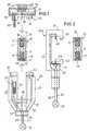
- eine Darstellung einer ersten Ausführungsformdes Stromschienensystems mit auseinandergenommenemStromabnehmer, wobei Schlitze an derOberseite und an der Unterseite der Profilschienevorhanden sind,
- Fig. 2
- eine zweite Ausführungsform des Stromschienensystems,ebenfalls mit Schlitzen an der Unterseiteund an der Oberseite der Profilschiene,
- Fig. 3
- eine dritte Ausführungsform, bei der Schlitzenur an der Oberseite der Profilschienevorhanden sind,
- Fig. 4
- eine vierte Ausführungsform,
- Fig. 5
- eine modifizierte Ausführungsform von Fig. 1und
- Fig. 6
- eine modifizierte Ausführungsform von Fig. 3.
- Fig. 1
- 2 shows a representation of a first embodiment of the busbar system with the pantograph taken apart, slots being provided on the top and on the bottom of the profile rail,
- Fig. 2
- A second embodiment of the busbar system, also with slots on the underside and on the top of the profile rail,
- Fig. 3
- a third embodiment in which there are slots only on the top of the profile rail,
- Fig. 4
- a fourth embodiment,
- Fig. 5
- a modified embodiment of Fig. 1 and
- Fig. 6
- a modified embodiment of Fig. 3rd
Bei dem Ausführungsbeispiel von Fig.1 ist eine Profilschiene 10vorgesehen, die abgehängt unter der Decke eines Raumes montiertwerden kann und ein über die gesamte Länge gleiches Profilaufweist. Die Profilschiene 10 enthält einen generellH-förmigen Schienenkörper 11 aus Metall, z. B. aus einemAluminium-Stranggusskörper. Er weist eine obere Nut 12 und eineuntere Nut 13 auf. In den Nuten 12 und 13 sitzt jeweils eineKunststoffleiste 14 bzw. 15. Diese Kunststoffleiste ist einU-förmiges Profil mit einem längslaufenden Schlitz 16, in demein längslaufender Stromleiter 17 verläuft. Der Stromleiter 17 besteht hier aus einem Runddraht der in dem Schlitz 16 derKunststoffleiste 14 bzw. 15 rastend festgehalten ist. DieKunststoffleisten können elastisch federn. In dem den Stromleiter17 umgebenden Bereich sind die Nuten 12, 13 an beidenWänden mit einer Ausbauchung 18 versehen, in der die Schenkelder Kunststoffleiste 14, 15 einrasten.1 is a
Gemäß Fig. 1 ist der eine Stromleiter 17 so angeordnet, dass erdurch den zugehörigen Schlitz 16 von der Oberseite 19 derProfilschiene 10 her kontaktierbar ist, während der andereStromleiter 17 von der Unterseite her kontaktierbar ist.1, the one
Der zugehörige Stromabnehmer 20 weist ein U-förmiges Gehäuse 21auf, mit zwei parallelen Seitenschenkeln 22, 23, die durcheinen unteren Querschenkel 24 verbunden sind. Das Gehäuse 21bildet eine insgesamt starre Einheit. Es bildet eine nach obenoffene Umfassung 25, in die von oben her die Profilschiene 10passend eingesetzt werden kann. Von dem Querschenkel 24 stehteine erste Kontaktzunge 26 ab, die in den unteren Schlitz 16der Profilschiene 10 eindringt und dabei in Kontakt mit demunteren Stromleiter 17 kommt. Die Kontaktzunge 26 ist mit einerLeitung 27 verbunden, die zusammen mit einer zweiten Leitung 28aus einer Kabeldurchführung 29 an der Unterseite des Querschenkels24 aus dem Gehäuse 21 herausführt. Die Leitungen 27und 28 sind die Zuleitungen einer an dem Stromabnehmer 20aufgehängten Leuchte 30. Die Kabeldurchführung 29 ist von einemSchraubenteil 31 umgeben, an dem die Leuchte 30 mechanischaufgehängt werden kann.The associated
Die Leitung 28 ist mit einem Kontaktelement 32 verbunden, dassals Kontaktbuchse ausgebildet und im Innern des Seitenschenkels22 untergebracht ist. Dieses Kontaktelement 32 greift mit einem als Kontaktstift ausgebildetem Kontaktelement 33 eines Kopfstücks34 zusammen.The
Das Kopfstück 34 weist eine Kappe 35 auf, die mit einem Innengewinde36 versehen ist, welches auf ein Außengewinde 37 an denoberen Enden der Seitenschenkel 22, 23 aufgeschraubt werdenkann. Dadurch kann die Kappe 35 fest mit dem Gehäuse 21verbunden werden, wobei die Profilschiene 10 vollständigumschlossen ist.The
Die Kappe 35 enthält einen Schieber 38, der von einer Feder 39am Kappenboden abgestützt ist. Der Schieber 38 trägt sowohl dasKontaktelement als auch die zweite Kontaktzunge 40, welchevorsteht und so angeordnet ist, dass sie in den oberen Schlitz16 der Profilschiene 10 eindringen kann. Schließlich weist derSchieber 38 noch eine Führungsbohrung 41 auf, die parallel zudem Kontaktelement 33 verläuft und in die ein Führungsstift 42des Seitenschenkels 23 eindringt, wenn das Kopfstück 34 auf demGehäuse 21 befestigt wird. Die Spitze des Führungsstiftes 42stößt gegen eine Kontaktfeder 43 und drückt diese gegen einenKontakt 44, der mit der Kontaktzunge 40 verbunden ist. DieKontaktfeder 43 ist mit dem Kontaktelement 33 verbunden. Siebildet mit dem Kontakt 44 einen Sicherheitsschalter 45, der dasStromschienenpotential nur dann zu dem Kontaktelement 33durchlässt, wenn das Kopfstück 34 ordnungsgemäß auf dem Gehäuse21 sitzt.The
Der Stromabnehmer 20 wird in der in Fig. 1 dargestellten Weisean die Profilschiene 10 angesetzt, indem das Gehäuse 21 vonunten her über die Profilschiene geschoben wird, bis die untereKontaktzunge 26 den zughörigen Stromleiter 17 erreicht hat.Dann wird das Kopfstück 34 von oben her aufgesetzt, wobei dieKontaktelemente 32 und 33 zusammengreifen. Dann wird das Kopfstück durch Drehen der Kappe 35 festgezogen, während derSchieber 38 unverdreht bleibt und zunehmend in das Gehäuse 21eingedrückt wird. Dabei gelangt die obere Kontaktzunge inKontakt mit dem oberen Stromleiter 17.The
Bei dem Ausführungsbeispiel der Fig. 2 ist die Profilschiene 10in gleicher Weise ausgebildet wie bei dem ersten Ausführungsbeispiel.Unterschiedlich ist der Stromabnehmer 20a, der hiereine die Profilschiene 10 umgreifende C-förmige Struktur hat,mit nur einem einzigen Seitenschenkel 22, der fest mit einemQuerschenkel 24 und einem Kopfstück 34 verbunden ist. Von demKopfstück 34 steht die obere Kontaktzunge nach unten ab.Außerdem weist das Kopfstück eine parallel zum Seitenschenkel22 verlaufende Halteleiste 50 auf.2 is the
Die untere Kontaktzunge 26 steht unter der Wirkung einervertikal wirkenden Feder 51. An dem Querschenkel 24 ist einfedernder Dreh-/ Klemmverschluss 52 befestigt, der in eineLösestellung gebracht werden kann, um die Profilschiene 10 inden Stromabnehmer einzusetzen. Danach wird der Verschluss festgeklemmt,um die Profilschiene festzuhalten.The
Bei dem Ausführungsbeispiel der Fig. 3 ist die Profilschiene10a mit zwei an ihrer Oberseite angeordneten Schlitzen 16versehen, durch die jeweils ein Stromleiter 17 zugänglich ist.Die Profilschiene 10a weist einen metallischen Schienenkörper11 aus einem Aluminiumprofil auf, der auch den Erdleiterbildet. Der Schienenkörper 11 enthält in einer Nut eineKunststoffleiste 14 mit den beiden vertikalen Schlitzen 16, indenen jeweils ein längslaufender Stromleiter 17 versenktangeordnet ist.3 is the
Der Stromabnehmer 20b weist zwei parallele Seitenschenkel 22,23 auf, wobei der Seitenschenkel 22 ein Kontaktelement 32 undder Seitenschenkel 23 ein Kontaktelement 55 enthält. DieKontaktelemente sind mit den beiden Leitern 27, 28 verbunden.Dazu komplementäre Kontaktelemente 33 und 56 sind an dem Kopfstück34 vorgesehen. Die beiden Kontaktzungen 26 und 40befinden sich ebenfalls an dem Schieber 38 des Kopfstücks, dervon einer Feder 39 abgestützt ist. Das Kopfstück 34 weist eineKappe 35 auf, die auf das Gehäuse 21 aufgeschraubt werden kannund den Schieber 38 enthält, der drehbar in der Kappe angeordnetist. Das Kopfstück 34 enthält wie bei dem erstenAusführungsbeispiel mindestens einen Sicherheitsschalter 45,der den Stromweg über die Kontaktzunge 26, bzw. 40 erstschließt, wenn das Kopfstück 34 ordnungsgemäß auf dem Gehäuse21 sitzt.The
Das Ausführungsbeispiel der Fig. 4 entspricht weitgehenddemjenigen von Fig. 2, jedoch unter Benutzung der Profilschiene10a, bei der beide Schlitze 16 an der Oberseite verlaufen.Folglich sind in dem Kopfstück 34 des Stromabnehmers 20c beideKontaktzungen 26, 40 an dem Kopfstück 34 vorgesehen. Es ist einDreh-/ Klemmverschluss 52 vorhanden, der dem Kopfstück 34gegenüberliegend angeordnet ist und der eine Montage desStromabnehmers an der Profilschiene 10a ermöglicht. DieLeitungen 27, 28 verlaufen durch den Querschenkel 24, denSeitenschenkel 22 und das Kopfstück 34 zu den Kontaktzungen 26,40.The embodiment of FIG. 4 largely correspondsthat of Fig. 2, but using the
Das Ausführungsbeispiel von Fig. 5 entspricht demjenigen vonFig. 1, mit dem Unterschied, dass der Sicherheitsschalter 45nicht vorhanden ist, und dass das Kontaktelement 33 mit einerisolierenden Hülse 60 mit radialem Abstand umgeben ist, die vondem Kopfstück 34 absteht. Das Kontaktelement 32 im Gehäuse 21 ist mit einer eng anliegenden Isolierung umgeben. Beim Aufsteckendes Kopfstücks auf das Gehäuse 21 dringt das stiftförmigeKontaktelement 33 in das buchsenförmige Kontaktelement32 ein, wobei die Hülse 66 sich außen über das Kontaktelement32 schiebt. Da das Kontaktelement 33 mit einer Hülse 60 alsBerührungsschutz versehen ist, ist ein Sicherheitsschalternicht erforderlich.The embodiment of FIG. 5 corresponds to that of1, with the difference that the
Bei dem Ausführungsbeispiel von Fig. 6 sind die Kontaktelemente33 und 56 des Kopfstücks 34 jeweils mit einer Hülse 60 bzw. 61als Berührungsschutz umgeben. Die Hülse 60, 61 ragt in axialerRichtung über das jeweilige Kontaktelement 33, 56 hinaus undschiebt sich beim Einstecken der Kontaktelemente des Kopfstücksin die Kontaktelemente 32, 55 des Gehäuses 21 über die buchsenförmigenKontaktelemente 32, 55. Ein Sicherheitsschalter istbei diesem Ausführungsbeispiel nicht vorhanden.6 are the
Claims (12)
Translated fromGermandadurch gekennzeichnet,dass mindestens einer der Schlitze (16) an der dem Bodenabgewandten Oberseite (19) der Profilschiene (10, 10a)angeordnet ist.High-voltage busbar system with a profile rail (10, 10a) which has longitudinal slots (16), in which current conductors (17) run, which from the outside through contact tongues (26, 40) of a current collector (20, 20a, 20b) suspended on the profile rail , 20c) can be reached,
characterized in that at least one of the slots (16) is arranged on the upper side (19) of the profile rail (10, 10a) facing away from the floor.
Applications Claiming Priority (2)
| Application Number | Priority Date | Filing Date | Title |
|---|---|---|---|
| DE20101581U | 2001-01-31 | ||
| DE20101581UDE20101581U1 (en) | 2001-01-31 | 2001-01-31 | High-voltage conductor rail system |
Publications (2)
| Publication Number | Publication Date |
|---|---|
| EP1233482A1true EP1233482A1 (en) | 2002-08-21 |
| EP1233482B1 EP1233482B1 (en) | 2004-04-21 |
Family
ID=7952266
Family Applications (1)
| Application Number | Title | Priority Date | Filing Date |
|---|---|---|---|
| EP02001391AExpired - LifetimeEP1233482B1 (en) | 2001-01-31 | 2002-01-19 | High voltage bus bar system |
Country Status (6)
| Country | Link |
|---|---|
| EP (1) | EP1233482B1 (en) |
| AT (1) | ATE265098T1 (en) |
| DE (2) | DE20101581U1 (en) |
| DK (1) | DK1233482T3 (en) |
| ES (1) | ES2218475T3 (en) |
| TR (1) | TR200401274T4 (en) |
Cited By (1)
| Publication number | Priority date | Publication date | Assignee | Title |
|---|---|---|---|---|
| EP2833490A1 (en) | 2013-07-31 | 2015-02-04 | Cefla Societa' Cooperativa | Electrified rail, particularly for powering metal shelving units, and method for its manufacturing |
Families Citing this family (1)
| Publication number | Priority date | Publication date | Assignee | Title |
|---|---|---|---|---|
| BE1028162B1 (en)* | 2020-03-25 | 2021-10-25 | Delta Light Nv | KIT, LIGHT ELEMENT, SENSOR ELEMENT, GUIDEWAY AND PROCEDURE FOR MOUNTING AN ELEMENT ON A GUIDEWAY |
Citations (6)
| Publication number | Priority date | Publication date | Assignee | Title |
|---|---|---|---|---|
| US4099817A (en)* | 1977-01-27 | 1978-07-11 | Donald J. Booty | Track lighting |
| DE3817133A1 (en)* | 1987-05-20 | 1988-12-01 | Halloform Gmbh & Co Kg | Low-voltage busbar |
| US4812134A (en)* | 1988-05-23 | 1989-03-14 | Miller Ruth E | Wall mounted lighting track system |
| EP0379244A1 (en)* | 1989-01-20 | 1990-07-25 | Janse Lichtreklame B.V. | Lighting system for advertising purposes |
| EP0871263A2 (en)* | 1997-04-11 | 1998-10-14 | Andreas Hierzer | Adaptor, Bus bar and coupling arrangement |
| EP0924814A2 (en)* | 1997-12-17 | 1999-06-23 | Alcatel | Current distribution rail for installation purposes |
Family Cites Families (3)
| Publication number | Priority date | Publication date | Assignee | Title |
|---|---|---|---|---|
| DE2327078A1 (en)* | 1972-05-29 | 1973-12-13 | Staff Kg | POWER DISTRIBUTION RAIL FOR COLLECTORS, IN PARTICULAR ADAPTERS |
| FR2595443B1 (en)* | 1986-03-06 | 1989-04-14 | Soleansky Christian | DEVICE FOR SUSPENSION AND LIGHTING OF OBJECTS |
| DE8620925U1 (en)* | 1986-08-04 | 1986-09-18 | Halloform GmbH, 4901 Hiddenhausen | Busbar, especially low-voltage busbar |
- 2001
- 2001-01-31DEDE20101581Upatent/DE20101581U1/ennot_activeExpired - Lifetime
- 2002
- 2002-01-19DKDK02001391Tpatent/DK1233482T3/enactive
- 2002-01-19TRTR2004/01274Tpatent/TR200401274T4/enunknown
- 2002-01-19ESES02001391Tpatent/ES2218475T3/ennot_activeExpired - Lifetime
- 2002-01-19DEDE50200361Tpatent/DE50200361D1/ennot_activeExpired - Lifetime
- 2002-01-19EPEP02001391Apatent/EP1233482B1/ennot_activeExpired - Lifetime
- 2002-01-19ATAT02001391Tpatent/ATE265098T1/enactive
Patent Citations (6)
| Publication number | Priority date | Publication date | Assignee | Title |
|---|---|---|---|---|
| US4099817A (en)* | 1977-01-27 | 1978-07-11 | Donald J. Booty | Track lighting |
| DE3817133A1 (en)* | 1987-05-20 | 1988-12-01 | Halloform Gmbh & Co Kg | Low-voltage busbar |
| US4812134A (en)* | 1988-05-23 | 1989-03-14 | Miller Ruth E | Wall mounted lighting track system |
| EP0379244A1 (en)* | 1989-01-20 | 1990-07-25 | Janse Lichtreklame B.V. | Lighting system for advertising purposes |
| EP0871263A2 (en)* | 1997-04-11 | 1998-10-14 | Andreas Hierzer | Adaptor, Bus bar and coupling arrangement |
| EP0924814A2 (en)* | 1997-12-17 | 1999-06-23 | Alcatel | Current distribution rail for installation purposes |
Cited By (1)
| Publication number | Priority date | Publication date | Assignee | Title |
|---|---|---|---|---|
| EP2833490A1 (en) | 2013-07-31 | 2015-02-04 | Cefla Societa' Cooperativa | Electrified rail, particularly for powering metal shelving units, and method for its manufacturing |
Also Published As
| Publication number | Publication date |
|---|---|
| DE20101581U1 (en) | 2002-06-20 |
| DE50200361D1 (en) | 2004-05-27 |
| TR200401274T4 (en) | 2004-07-21 |
| ES2218475T3 (en) | 2004-11-16 |
| EP1233482B1 (en) | 2004-04-21 |
| DK1233482T3 (en) | 2004-06-01 |
| ATE265098T1 (en) | 2004-05-15 |
Similar Documents
| Publication | Publication Date | Title |
|---|---|---|
| DE19951789A1 (en) | Connection terminal | |
| DE69311591T2 (en) | Connection device for a low-voltage switch with a plastic housing | |
| EP0017163B1 (en) | Cover for terminals of electrical switches | |
| EP0075280A2 (en) | Clamping screw | |
| EP1233482B1 (en) | High voltage bus bar system | |
| DE8206021U1 (en) | WARNING DEVICE FOR PAD WEAR ON BRAKE SHOES | |
| DE2743033A1 (en) | Multipolar safety plug ensuring correct interconnections are made - has GFR plastic, esp. polycarbonate coding comb with lugs which must be removed to permit plug-in | |
| EP0762583A2 (en) | Low voltage bus bar system | |
| DE3413740C2 (en) | ||
| DE102019112536A1 (en) | Connector for the frontal connection of light rails | |
| DE69302103T2 (en) | Terminal block for a modular electrical device | |
| DE4110251C2 (en) | ||
| EP1868265B1 (en) | Lead connection for a clamp fitted on a top hat rail | |
| EP0451723B1 (en) | Quick fixing device to snap an installation device onto a standard rail | |
| DE4420072A1 (en) | Device for connecting electrical conductors to a switching apparatus | |
| DE2629090C2 (en) | Fastening device with locking function for an electrical assembly arranged on a mounting rail | |
| DE19817934C1 (en) | Power supply for longitudinally slotted conductor lines | |
| EP1028488B1 (en) | Connecting terminal for an electrical apparatus | |
| DE7902093U1 (en) | Contact insert, consisting of a clamping spring and a contact frame, in particular for light strips | |
| DE3007970A1 (en) | ELECTRICAL SWITCHGEAR | |
| DE1765056A1 (en) | Connection rail for the supply of consumers with electricity | |
| DE4011446A9 (en) | Quick fastening device for snapping an installation device onto a standard mounting rail | |
| DE1268249B (en) | Switchgear terminal block for protective conductor | |
| DE1168990B (en) | Neutral disconnect terminal strip | |
| DE10053035A1 (en) | Leaf spring grip for connecting electrical conductors has a supporting block made from a profiled strip having a retaining element and a recess with a slot open on the side, also a leaf spring anchored in the recess. |
Legal Events
| Date | Code | Title | Description |
|---|---|---|---|
| PUAI | Public reference made under article 153(3) epc to a published international application that has entered the european phase | Free format text:ORIGINAL CODE: 0009012 | |
| AK | Designated contracting states | Kind code of ref document:A1 Designated state(s):AT BE CH CY DE DK ES FI FR GB GR IE IT LI LU MC NL PT SE TR | |
| AX | Request for extension of the european patent | Free format text:AL;LT;LV;MK;RO;SI | |
| 17P | Request for examination filed | Effective date:20021210 | |
| 17Q | First examination report despatched | Effective date:20030401 | |
| AKX | Designation fees paid | Designated state(s):AT BE CH CY DE DK ES FI FR GB GR IE IT LI LU MC NL PT SE TR | |
| GRAP | Despatch of communication of intention to grant a patent | Free format text:ORIGINAL CODE: EPIDOSNIGR1 | |
| GRAS | Grant fee paid | Free format text:ORIGINAL CODE: EPIDOSNIGR3 | |
| GRAA | (expected) grant | Free format text:ORIGINAL CODE: 0009210 | |
| AK | Designated contracting states | Kind code of ref document:B1 Designated state(s):AT BE CH CY DE DK ES FI FR GB GR IE IT LI LU MC NL PT SE TR | |
| PG25 | Lapsed in a contracting state [announced via postgrant information from national office to epo] | Ref country code:FI Free format text:LAPSE BECAUSE OF FAILURE TO SUBMIT A TRANSLATION OF THE DESCRIPTION OR TO PAY THE FEE WITHIN THE PRESCRIBED TIME-LIMIT Effective date:20040421 | |
| REG | Reference to a national code | Ref country code:GB Ref legal event code:FG4D Free format text:NOT ENGLISH | |
| REG | Reference to a national code | Ref country code:CH Ref legal event code:EP | |
| RAP2 | Party data changed (patent owner data changed or rights of a patent transferred) | Owner name:OLIGO LICHTTECHNIK GMBH | |
| RIN2 | Information on inventor provided after grant (corrected) | Inventor name:KEFERSTEIN, RALF | |
| REG | Reference to a national code | Ref country code:IE Ref legal event code:FG4D Free format text:GERMAN | |
| REF | Corresponds to: | Ref document number:50200361 Country of ref document:DE Date of ref document:20040527 Kind code of ref document:P | |
| REG | Reference to a national code | Ref country code:CH Ref legal event code:NV Representative=s name:ISLER & PEDRAZZINI AG | |
| REG | Reference to a national code | Ref country code:DK Ref legal event code:T3 | |
| NLT2 | Nl: modifications (of names), taken from the european patent patent bulletin | Owner name:OLIGO LICHTTECHNIK GMBH | |
| PG25 | Lapsed in a contracting state [announced via postgrant information from national office to epo] | Ref country code:GR Free format text:LAPSE BECAUSE OF FAILURE TO SUBMIT A TRANSLATION OF THE DESCRIPTION OR TO PAY THE FEE WITHIN THE PRESCRIBED TIME-LIMIT Effective date:20040721 | |
| GBT | Gb: translation of ep patent filed (gb section 77(6)(a)/1977) | Effective date:20040701 | |
| REG | Reference to a national code | Ref country code:SE Ref legal event code:TRGR | |
| ET | Fr: translation filed | ||
| REG | Reference to a national code | Ref country code:ES Ref legal event code:FG2A Ref document number:2218475 Country of ref document:ES Kind code of ref document:T3 | |
| PG25 | Lapsed in a contracting state [announced via postgrant information from national office to epo] | Ref country code:LU Free format text:LAPSE BECAUSE OF NON-PAYMENT OF DUE FEES Effective date:20050119 Ref country code:CY Free format text:LAPSE BECAUSE OF FAILURE TO SUBMIT A TRANSLATION OF THE DESCRIPTION OR TO PAY THE FEE WITHIN THE PRESCRIBED TIME-LIMIT Effective date:20050119 | |
| PG25 | Lapsed in a contracting state [announced via postgrant information from national office to epo] | Ref country code:MC Free format text:LAPSE BECAUSE OF NON-PAYMENT OF DUE FEES Effective date:20050131 | |
| PLBE | No opposition filed within time limit | Free format text:ORIGINAL CODE: 0009261 | |
| STAA | Information on the status of an ep patent application or granted ep patent | Free format text:STATUS: NO OPPOSITION FILED WITHIN TIME LIMIT | |
| 26N | No opposition filed | Effective date:20050124 | |
| REG | Reference to a national code | Ref country code:CH Ref legal event code:PCAR Free format text:ISLER & PEDRAZZINI AG;POSTFACH 1772;8027 ZUERICH (CH) | |
| PG25 | Lapsed in a contracting state [announced via postgrant information from national office to epo] | Ref country code:PT Free format text:LAPSE BECAUSE OF NON-PAYMENT OF DUE FEES Effective date:20040921 | |
| REG | Reference to a national code | Representative=s name:WAGNER ALBIGER & PARTNER PATENTANWAELTE MBB, DE Ref country code:DE Ref legal event code:R082 Ref document number:50200361 Country of ref document:DE Ref country code:DE Ref legal event code:R082 Ref document number:50200361 Country of ref document:DE Representative=s name:MUELLER-GERBES WAGNER ALBIGER PATENTANWAELTE, DE | |
| PGFP | Annual fee paid to national office [announced via postgrant information from national office to epo] | Ref country code:BE Payment date:20140122 Year of fee payment:13 Ref country code:SE Payment date:20140123 Year of fee payment:13 Ref country code:IE Payment date:20140121 Year of fee payment:13 Ref country code:DK Payment date:20140127 Year of fee payment:13 | |
| PGFP | Annual fee paid to national office [announced via postgrant information from national office to epo] | Ref country code:FR Payment date:20140124 Year of fee payment:13 Ref country code:ES Payment date:20140122 Year of fee payment:13 Ref country code:IT Payment date:20140128 Year of fee payment:13 Ref country code:TR Payment date:20140114 Year of fee payment:13 | |
| PGFP | Annual fee paid to national office [announced via postgrant information from national office to epo] | Ref country code:GB Payment date:20140123 Year of fee payment:13 | |
| PG25 | Lapsed in a contracting state [announced via postgrant information from national office to epo] | Ref country code:BE Free format text:LAPSE BECAUSE OF NON-PAYMENT OF DUE FEES Effective date:20150131 | |
| REG | Reference to a national code | Ref country code:DK Ref legal event code:EBP Effective date:20150131 | |
| REG | Reference to a national code | Ref country code:SE Ref legal event code:EUG | |
| GBPC | Gb: european patent ceased through non-payment of renewal fee | Effective date:20150119 | |
| PG25 | Lapsed in a contracting state [announced via postgrant information from national office to epo] | Ref country code:GB Free format text:LAPSE BECAUSE OF NON-PAYMENT OF DUE FEES Effective date:20150119 | |
| REG | Reference to a national code | Ref country code:FR Ref legal event code:ST Effective date:20150930 | |
| REG | Reference to a national code | Ref country code:IE Ref legal event code:MM4A | |
| PG25 | Lapsed in a contracting state [announced via postgrant information from national office to epo] | Ref country code:FR Free format text:LAPSE BECAUSE OF NON-PAYMENT OF DUE FEES Effective date:20150202 Ref country code:SE Free format text:LAPSE BECAUSE OF NON-PAYMENT OF DUE FEES Effective date:20150120 | |
| PG25 | Lapsed in a contracting state [announced via postgrant information from national office to epo] | Ref country code:IT Free format text:LAPSE BECAUSE OF NON-PAYMENT OF DUE FEES Effective date:20150119 | |
| PG25 | Lapsed in a contracting state [announced via postgrant information from national office to epo] | Ref country code:IE Free format text:LAPSE BECAUSE OF NON-PAYMENT OF DUE FEES Effective date:20150119 Ref country code:DK Free format text:LAPSE BECAUSE OF NON-PAYMENT OF DUE FEES Effective date:20150131 | |
| REG | Reference to a national code | Ref country code:ES Ref legal event code:FD2A Effective date:20160226 | |
| PG25 | Lapsed in a contracting state [announced via postgrant information from national office to epo] | Ref country code:ES Free format text:LAPSE BECAUSE OF NON-PAYMENT OF DUE FEES Effective date:20150120 | |
| PG25 | Lapsed in a contracting state [announced via postgrant information from national office to epo] | Ref country code:TR Free format text:LAPSE BECAUSE OF NON-PAYMENT OF DUE FEES Effective date:20150119 | |
| PGFP | Annual fee paid to national office [announced via postgrant information from national office to epo] | Ref country code:CH Payment date:20190124 Year of fee payment:18 Ref country code:NL Payment date:20190122 Year of fee payment:18 Ref country code:DE Payment date:20190227 Year of fee payment:18 | |
| PGFP | Annual fee paid to national office [announced via postgrant information from national office to epo] | Ref country code:AT Payment date:20190118 Year of fee payment:18 | |
| REG | Reference to a national code | Ref country code:DE Ref legal event code:R082 Ref document number:50200361 Country of ref document:DE Representative=s name:WAGNER ALBIGER & PARTNER PATENTANWAELTE MBB, DE Ref country code:DE Ref legal event code:R081 Ref document number:50200361 Country of ref document:DE Owner name:OLIGO LICHTTECHNIK GMBH, DE Free format text:FORMER OWNER: OLIGO LICHTTECHNIK GMBH, 53773 HENNEF, DE | |
| REG | Reference to a national code | Ref country code:DE Ref legal event code:R119 Ref document number:50200361 Country of ref document:DE | |
| REG | Reference to a national code | Ref country code:CH Ref legal event code:PL | |
| REG | Reference to a national code | Ref country code:NL Ref legal event code:MM Effective date:20200201 | |
| REG | Reference to a national code | Ref country code:AT Ref legal event code:MM01 Ref document number:265098 Country of ref document:AT Kind code of ref document:T Effective date:20200119 | |
| PG25 | Lapsed in a contracting state [announced via postgrant information from national office to epo] | Ref country code:DE Free format text:LAPSE BECAUSE OF NON-PAYMENT OF DUE FEES Effective date:20200801 Ref country code:NL Free format text:LAPSE BECAUSE OF NON-PAYMENT OF DUE FEES Effective date:20200201 | |
| PG25 | Lapsed in a contracting state [announced via postgrant information from national office to epo] | Ref country code:CH Free format text:LAPSE BECAUSE OF NON-PAYMENT OF DUE FEES Effective date:20200131 Ref country code:AT Free format text:LAPSE BECAUSE OF NON-PAYMENT OF DUE FEES Effective date:20200119 Ref country code:LI Free format text:LAPSE BECAUSE OF NON-PAYMENT OF DUE FEES Effective date:20200131 |