EP1231874B1 - Adjustable spinal brace - Google Patents
Adjustable spinal braceDownload PDFInfo
- Publication number
- EP1231874B1 EP1231874B1EP00928033AEP00928033AEP1231874B1EP 1231874 B1EP1231874 B1EP 1231874B1EP 00928033 AEP00928033 AEP 00928033AEP 00928033 AEP00928033 AEP 00928033AEP 1231874 B1EP1231874 B1EP 1231874B1
- Authority
- EP
- European Patent Office
- Prior art keywords
- pad
- spinal brace
- brace according
- lumbar
- pressure
- Prior art date
- Legal status (The legal status is an assumption and is not a legal conclusion. Google has not performed a legal analysis and makes no representation as to the accuracy of the status listed.)
- Expired - Lifetime
Links
- 230000003187abdominal effectEffects0.000claimsabstractdescription28
- 210000000988bone and boneAnatomy0.000claimsabstractdescription6
- 210000004197pelvisAnatomy0.000claimsabstractdescription6
- 210000001015abdomenAnatomy0.000claimsdescription4
- 210000001562sternumAnatomy0.000claimsdescription2
- 208000002193PainDiseases0.000description11
- 208000007623LordosisDiseases0.000description9
- 230000000694effectsEffects0.000description7
- 238000012360testing methodMethods0.000description7
- 238000005452bendingMethods0.000description6
- 210000004705lumbosacral regionAnatomy0.000description6
- 210000004872soft tissueAnatomy0.000description4
- 230000003019stabilising effectEffects0.000description4
- 239000006260foamSubstances0.000description3
- 210000001624hipAnatomy0.000description3
- 210000002414legAnatomy0.000description3
- 208000008035Back PainDiseases0.000description2
- 208000008930Low Back PainDiseases0.000description2
- 239000000463materialSubstances0.000description2
- 210000000115thoracic cavityAnatomy0.000description2
- 206010019909HerniaDiseases0.000description1
- 210000000481breastAnatomy0.000description1
- 210000000038chestAnatomy0.000description1
- 239000002131composite materialSubstances0.000description1
- 230000001419dependent effectEffects0.000description1
- 239000004744fabricSubstances0.000description1
- 210000004013groinAnatomy0.000description1
- 210000004394hip jointAnatomy0.000description1
- 230000001045lordotic effectEffects0.000description1
- 238000012986modificationMethods0.000description1
- 230000004048modificationEffects0.000description1
- 239000004033plasticSubstances0.000description1
- 229920003023plasticPolymers0.000description1
- 230000008092positive effectEffects0.000description1
- 230000000284resting effectEffects0.000description1
- 208000005198spinal stenosisDiseases0.000description1
- 230000006641stabilisationEffects0.000description1
- 239000000725suspensionSubstances0.000description1
- 239000012815thermoplastic materialSubstances0.000description1
- 229920001187thermosetting polymerPolymers0.000description1
Images


Classifications
- A—HUMAN NECESSITIES
- A61—MEDICAL OR VETERINARY SCIENCE; HYGIENE
- A61F—FILTERS IMPLANTABLE INTO BLOOD VESSELS; PROSTHESES; DEVICES PROVIDING PATENCY TO, OR PREVENTING COLLAPSING OF, TUBULAR STRUCTURES OF THE BODY, e.g. STENTS; ORTHOPAEDIC, NURSING OR CONTRACEPTIVE DEVICES; FOMENTATION; TREATMENT OR PROTECTION OF EYES OR EARS; BANDAGES, DRESSINGS OR ABSORBENT PADS; FIRST-AID KITS
- A61F5/00—Orthopaedic methods or devices for non-surgical treatment of bones or joints; Nursing devices ; Anti-rape devices
- A61F5/01—Orthopaedic devices, e.g. long-term immobilising or pressure directing devices for treating broken or deformed bones such as splints, casts or braces
- A61F5/02—Orthopaedic corsets
- A61F5/024—Orthopaedic corsets having pressure pads connected in a frame for reduction or correction of the curvature of the spine
Definitions
- the present inventionrelates to an adjustable spinal brace, according to the preamble of claim 1.
- braces and other orthotic devicesare known in the art.
- spinal braces with various heightssome intending to immobilise and stabilise the entire spine - thoracic as well as lumbar areas.
- Other types of spinal braces - low type -are only stabilising the lower part of the spine - the lumbar area.
- the rigidity of the bracevaries a lot from soft braces made of fabrics to rigid braces made of plastics.
- prior art bracescomprise frontal breast or abdominal plates or elements and anterior dorsal plates or elements interconnected by straps and rolls to apply stabilising or immobilising pressures.
- Examples of the prior artmay be found in the US patents Nos. 2,813,526, 4,285,336 and 4,930,499.
- a problem with the prior artis that it is difficult to set the exact magnitude and position of the pressure by means of tightening straps. In this connection, it is critical that the position and magnitude of the pressure applied is correct because otherwise the patient does not experience any pain relief.
- abdominal and dorsal elementsare large and encumber the movements of the body, e.g. lateral bending and movements of the arms and legs as well as sitting.
- test instrumentfor testing spinal braces is previously known.
- the test instrumentwas developed by one of the present inventors and patented in Sweden under No. 8505547-3, corresponding to US 4 821 739.
- the test instrumentincludes various means for adjusting the size of the brace and magnitude and position of the applied pressure.
- this test instrumentis not suitable for day to day use because the design featured protruding screws and the like and was not generally designed for wearing under clothes. Even so, the test instrument was sometimes used as a brace for shorter periods.
- US Patent No.3,945,376describes a spinal orthosis provided with iliac elements (iliac crests).
- the preamble of claim 1is based on this document.
- the iliac crestsare formed of a flexible material, such as a rubber hose.
- a pelvic band of the orthosisis placed round the hip and not connected to the iliac crests. This results in that it is difficult to put on or take of the orthosis, especially to place it reproducibly in the correct position.
- the orthosislacks a lumbar pad to adjust the shape of the lordosis. The orthosis is just applied with varying pressure in the different parts.
- the present inventionsolves the above problems by providing an adjustable spinal brace which is easily and reproducibly positioned on the body of a patient thanks to a connection means having lateral iliac rolls which are fitted at the top of the pelvis bone. Also, it is easy to adjust the magnitude and position of the applied pressure thanks to a lumbar pad provided with pressure setting means. Also, the lumbar pad may be positioned at different heights and the pressure point may be shifted in a lateral direction.
- the inventionprovides an adjustable spinal brace, especially a lumbar brace, which is multi-adjustable for conservative treatment of low back pain.
- the painmay have various causes, such as discogenic hernia, spinal stenose, spondylotisthesis etc.
- the brace of the inventionis a further development of the test instrument mentioned in the introduction, which is a tool to prove that conservative treatment could be effective.
- the present braceis designed for individual use during day and night. The design of the brace if virtually open at the lateral side, which allows for lateral bending. In general, the brace stabilises the spine in the sagittal plane.
- braceOne purpose of the brace is to stabilise the lumbar spine by the use of a "three point pressure" brace. Also, the brace restores lumbar lordosis to the individual needs by a multi-adjustable posterior lumbar pad.
- a lightweight posterior framebridges the lumbar spine from the distal end of the sacrum until the tenth thoracic vertebra T10, approximately two fingers below the scapulae.
- Two iliac rollsconnected to the posterior frame, position this frame over the pelvis. In this situation the frame finds a reliable "grip" between the lower ribs and the pelvis, which can be maintained efficiently.
- the iliac rollshave virtually just “one" position where they can actually be. This is extremely important, since the adjustments of the posterior lumbar pad 2 and the accuracy of this position after putting on the brace relies fully on the position of the iliac rolls, which at the same time will pull the abdominal pad into the soft tissue of the abdomen to create the third point in achieving the desired stabilisation of the lumbar spine.
- the "three point pressure"When properly applied to the body, the "three point pressure" will stabilise the lumbar spine into a more or less lordotic position with reduced lordosis. All functional parts are integrated within the frame and do hardly interfere with activities like sitting, standing, walking or lying.
- FIG. 1shows the brace according to the invention in a partially exploded view.
- the bracehas a posterior frame 1 to be placed at the back of the patient.
- the frame 1comprises two horizontal supports, a cranial support 5 and a caudal support 6.
- the horizontal supports 5, 6are attached to two vertical H-shaped struts 12 by means of a respective set of screws.
- the horizontal cranial support 5can be adjusted vertically over a range of 50 mm. Also the caudal support 6 can be adjusted vertically over a range of 50 mm.
- the total height of the frame Ican be adjusted from 390 to 490 mm. This adjustment range is sufficient for 98 % of the population. The dimensions may of course be varied to provide other sizes.
- the iliac rolls 3are intended to be positioned at the crista iliaca, that is they will rest on top of the pelvis bone.
- the iliac rollsare attached by means of elastic straps 4 and push buttons 19 to an anterior abdominal pad 7.
- the cranial and caudal supports 5, 6may be connected with straps to the abdominal pad 7. Only one lower strap 4 is shown in figure 1.
- the posterior lumbar pad 2is attached to the posterior frame 1 as is described more in detail with reference to figures 4, 5A and 5B.
- the vertical struts 12consist of an "H" profile, with lateral openings.
- the shape of the struts 12 along the back of the patientis adapted to the anatomical shape of the human body.
- the openings and flanges of the "H" profileare useful for attachment of the horizontal supports 5, 6, the iliac rolls as well as a multi-adjustable posterior lumbar pad 2.
- the cranial and caudal horizontal supportsare padded with foam (not shown).
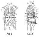
- the braceis shown from the front as fastened on a patient.
- the skeleton bones on the patientare indicated for reference.
- the iliac rolls and their straps 4are located at the waist.
- Figure 3shows a similar view to figure 2 from the side. As is more clearly seen in figure 3, the iliac rolls 3 are resting against crista iliaca (with some soft tissue in between).
- Figure 4is a dorsal view of the suspension mechanism for the posterior lumbar pad 2. See also figures 5A and 5B.
- the lumbar pad 2is attached by means of a mounting plate 17.
- the mounting plate 17has a shaft such that the pad 2 may be rotated round a horizontal axis.
- the mounting plate 17is connected by two pairs of legs 16 to the vertical struts 12.
- the legs 16have pins 21 at the ends remote from the mounting plate 17.
- the pinsare inserted in blocks 20 sliding in the H-shaped struts 12. Only the top blocks 20 are shown in figure 4.
- the blocks 20may also carry set screws 9 for securing the lumbar pad 12 at a suitable height as is described more in detail below.
- the pins 21are carried by or integral with a respective sleeve 22.
- the sleeve 22also carries a bracket 13 with a row of holes 14.
- An adjustment screw 8is fastened in one pair of the holes 14, normally the centre pair. As is shown, the screw 8 has a pair of oppositely directed threads, such that the distance between the top and lower sleeve 22 may be adjusted accurately by screwing the screw 8. The screw 8 may be shifted to the left and right by using another pair of holes 14 for the reason described more in detail below.
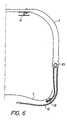
- Figure 5Ashows the lumbar pad 2 in its completely retracted position. In this position the pad 2 is hardly touching the back of the patient but hidden in within the posterior frame 1. In figure 5B the pad is shown in an extended position. The maximum extension may be e.g. 50 mm.
- the iliac rolls 3are connected via elastic straps 4 with push buttons 19, strings 10 and string locks 11 to the anterior abdominal pad 7 for applying the abdominal pressure.
- the strings 10may be guided around a respective pulley block 23.
- One end of the stringis attached to the abdominal pad at the push button (via the strap 4) and the other end of the string is attached to the string lock 11 after tightening.
- the string lock 11 and pulley block 23make it possible to apply sufficient pressure in an efficient and easy way by tightening the strings 10 attached to the elastic straps 4 of the iliac rolls 3. This arrangement is easy to handle for the patient or doctor to achieve a sufficient tension and pressure.
- Figure 6also shows how the iliac rolls are attached to the H-shaped struts with screws.
- the iliac rollscarry a number of holes so that the width of the brace is easily adjusted by using the set of holes providing the suitable width for the patient.
- the anterior abdominal pad 7applies the abdominal lumbar pressure. It is a lightweight concave pad, which should cover the abdomen from the symphysis up to the sternum point. From left lateral to right lateral the abdominal pad 7 should bridge the distance between the two iliac rolls 3. The cranial border of the pad is shaped after the lower ribs. The abdominal pad should be able to apply considerable pressure without changing shape and is therefore constructed out of a thermosetting composite. The pad may be tailored individually for the patient. The pad is furnished with (parts of) pushbuttons for attachment of the straps 4 and string locks 11 for the strings. For comfort the pad is lined with foam padding (not shown).
- the lordosiscould be restored to the individual needs by means of the multi-adjustable posterior lumbar pad 2. In a non-functional position this lumbar pad will be hidden in the frame. Then, the three point pressure is applied by the horizontal support 5 and the horizontal caudal support 6 together with the anterior abdominal pad 7.
- the padcan be moved vertically by sliding in the H-shaped vertical struts 12.
- the paditself is curved and somewhat flexible to follow the curvature of the lumbar portion of the back.
- the padis lined with foam padding 18. It is suspended by means of a mounting plate 17 and a shaft such that it can turn around a horizontal axis.
- the centrecan be positioned from vertebra L4 through T12; the most common area will be from L3 to L1.
- the vertically placed adjusting screw 8preferably a socket head cap screw
- the posterior lumbar padcan be adjusted to apply pressure in the anterior direction.
- the lumbar pad 2is maintained at the suitable height by means of the pressure and friction against the back of the patient.
- set screws 9can keep the lumbar pad in place.
- the mechanismwill respond asymmetrically (like a trapezoid with two parallel vertical sides). If for instance the right vertical side is longer, the pressure at the right side appears to be higher. By shifting the vertical adjusting screw to the right a compensation for this higher pressure can be accomplished. This way it becomes possible to balance the rotational forces of the spine.
- a person with low back painis in general fully capable in deciding in what level (height) and how strong (depth) the pad should be applied.
- a good starting positionis to put the centre of the pad at the level of the L3 vertebra, which is at the 0-level (spine tangent to vertical)of the lordosis (without the compensation provided by the invention).
- the braceis put on by placing the iliac rolls at the crista iliaca and fastening the straps 4 by means of the push buttons.
- the strapsare tightened by means of the strings 10 and the pulley blocks 23 and the string locks 11 such that a suitable pressure is obtained.
- the upper and lower straps 4are attached to the cranial 5 and caudal supports, respectively.
- the doctorcan apply pressure to the lumbar spine by means of the lumbar pad and restore lordosis against the pressure of the abdominal pad 7.
- the surface area of the anterior abdominal padneeds to be considerable bigger than the surface of the posterior lumbar pad.
- the adjustments of the screw-jackcan be used to compensate for the counter-pressure of the spine and the soft tissue.
- Asymmetrical pressure on the posterior lumbar padwill result in an asymmetrical position of the screw-jack. If a compensation of these forces is required the adjusting screw can be shifted to the side where the pressure is highest, thus compensating and restoring the balance. Since the abdominal pressure acts as a counter pressure for all forces the user of the brace can feel these differences at his abdomen as a result of the higher pressure against the abdominal pad.
Landscapes
- Health & Medical Sciences (AREA)
- Public Health (AREA)
- Veterinary Medicine (AREA)
- Engineering & Computer Science (AREA)
- Biomedical Technology (AREA)
- Heart & Thoracic Surgery (AREA)
- Vascular Medicine (AREA)
- Life Sciences & Earth Sciences (AREA)
- Animal Behavior & Ethology (AREA)
- General Health & Medical Sciences (AREA)
- Nursing (AREA)
- Orthopedic Medicine & Surgery (AREA)
- Orthopedics, Nursing, And Contraception (AREA)
- Chairs For Special Purposes, Such As Reclining Chairs (AREA)
- Chairs Characterized By Structure (AREA)
- Chair Legs, Seat Parts, And Backrests (AREA)
- Pharmaceuticals Containing Other Organic And Inorganic Compounds (AREA)
- Seats For Vehicles (AREA)
- Mechanical Treatment Of Semiconductor (AREA)
- Control Of Eletrric Generators (AREA)
- Transplanting Machines (AREA)
- Control Of Throttle Valves Provided In The Intake System Or In The Exhaust System (AREA)
Abstract
Description
- allowing an individual assessment of the shape of the lumbar lordosisgiving a maximal pain relief;
- allowing a support in the optimal pain relieving level of the lumbarspine;
- allowing a sufficient abdominal counterpressure to stabilize the deviceand keep the correct level of the lumbar lordosis, also to increase the intraabdominalpressure to decrease the intradiscal pressure (pain relieving effect);
- allowing the iliac rolls to be stabilised over the crista iliaca, thusstabilising the device and preventing it from sliding up or down, which would movethe dorsal plate up and down and thus loosing the level of optimal pain relief;
- allowing a moderate side-bending of the trunk to improve theacceptance of the brace treatment;
- allowing at least 90° bending of the hip joints i.e. when sitting in a car;
- allowing an improved movement of the arms and the upper part of thetrunk and avoiding unpleasant pressure of the upper edges of the device usuallyseen in conventional rigid braces.
Claims (10)
- An adjustable spinal brace comprising an anterior abdominal pad (7), aposterior frame (1) and lateral iliac rolls (3), said iliac rolls (3) to be positioned atthe top of the pelvis bone (crista iliaca), and the abdominal pad (7) and the posteriorframe (1) being interconnected by a connection means, wherein theconnection means comprises said iliac rolls (3) and straps (4) to be connected to theanterior abdominal pad (7),characterised in that the posterior frame (1) has an adjustablelumbar pad (2) provided with pressure setting means (8), the pressure setting meanscomprising a screw jack having legs (16) and an adjusting screw (8) connected tosaid legs (16) for adjusting the distance between the legs and setting the distancebetween the lumbar pad (2) and the posterior frame (1), thereby enabling anadjustment of the applied pressure.
- A spinal brace according to claim 1,characterised in that the adjustingscrew (8) is placed vertically.
- A spinal brace according to claim 2,characterised in that the position ofthe screw (8) of the screw jack is adjustable in the lateral direction.
- A spinal brace according to claim 1, 2 or 3,characterised in that thelumbar pad also (2) is adjustable in height.
- A spinal brace according to any of the previous claims,characterised inthat the posterior frame (1) comprises two vertical struts (12), a cranial horizontalsupport (5) and a caudal horizontal support (6).
- A spinal brace according to claim 5,characterised in that the cranialhorizontal support (5) and the caudal horizontal supports (6) are adjustable inheight.
- A spinal brace according to any of the previous claims,characterised inthat straps (4) are provided between the iliac rolls (3) and the abdominal pad (7).
- A spinal brace according to claim 7 and 5 or 6,characterised in thatstraps (4) are provided between the horizontal supports (5, 6) and the abdominal pad(7).
- A spinal brace according to any of the previous claims,characterised inthat the anterior abdominal pad (7) is lightweight and concave and adapted to coverthe abdomen substantially from the symphysis to the sternum point.
- A spinal brace according to claim 9,characterised in that the cranialborder of the anterior abdominal pad (7) is shaped after the lower ribs.
Priority Applications (1)
| Application Number | Priority Date | Filing Date | Title |
|---|---|---|---|
| DK00928033TDK1231874T3 (en) | 1999-04-30 | 2000-04-17 | Adjustable backrest |
Applications Claiming Priority (3)
| Application Number | Priority Date | Filing Date | Title |
|---|---|---|---|
| SE9901556 | 1999-04-30 | ||
| SE9901556ASE9901556L (en) | 1999-04-30 | 1999-04-30 | Adjustable back orthosis |
| PCT/SE2000/000727WO2000066047A1 (en) | 1999-04-30 | 2000-04-17 | Adjustable spinal brace |
Publications (2)
| Publication Number | Publication Date |
|---|---|
| EP1231874A1 EP1231874A1 (en) | 2002-08-21 |
| EP1231874B1true EP1231874B1 (en) | 2005-03-02 |
Family
ID=20415410
Family Applications (1)
| Application Number | Title | Priority Date | Filing Date |
|---|---|---|---|
| EP00928033AExpired - LifetimeEP1231874B1 (en) | 1999-04-30 | 2000-04-17 | Adjustable spinal brace |
Country Status (15)
| Country | Link |
|---|---|
| US (1) | US20050203453A1 (en) |
| EP (1) | EP1231874B1 (en) |
| JP (1) | JP2002542888A (en) |
| KR (1) | KR20020033614A (en) |
| CN (1) | CN1230136C (en) |
| AT (1) | ATE289788T1 (en) |
| AU (1) | AU763952B2 (en) |
| CA (1) | CA2372196A1 (en) |
| DE (1) | DE60018449T2 (en) |
| DK (1) | DK1231874T3 (en) |
| ES (1) | ES2237426T3 (en) |
| NO (1) | NO317824B1 (en) |
| PL (1) | PL351172A1 (en) |
| SE (2) | SE9901556L (en) |
| WO (1) | WO2000066047A1 (en) |
Families Citing this family (23)
| Publication number | Priority date | Publication date | Assignee | Title |
|---|---|---|---|---|
| WO2006068459A1 (en) | 2004-12-21 | 2006-06-29 | Petrus Johannes Maria Van Loon | Brace and method for treatment of spinal deformities |
| FR2909861B1 (en)* | 2006-12-19 | 2009-10-30 | Patrick Faouen | ORTHOPEDIC DEVICE FOR CORRECTING POSTURE BY TRUNK CONTENT |
| US7833182B2 (en)* | 2007-03-14 | 2010-11-16 | Hughes Phillip K | Back support apparatus and method |
| CN101099700B (en)* | 2007-08-03 | 2010-09-01 | 周林斌 | Back-support waist-protection device |
| JP2014226523A (en)* | 2013-05-17 | 2014-12-08 | 株式会社 P.O.ラボ | Trunk orthosis |
| JP6578300B2 (en) | 2014-01-17 | 2019-09-18 | トンプソン、マシュー | Orthosis for deformation correction |
| PL408677A1 (en) | 2014-06-26 | 2016-01-04 | Ori-Med Spółka Z Ograniczoną Odpowiedzialnością | Orthopedic jacket, preferably for spinal column rehabilitation |
| JP6350990B2 (en)* | 2014-10-09 | 2018-07-04 | パナソニックIpマネジメント株式会社 | Pelvic belt |
| US12004988B2 (en)* | 2015-04-03 | 2024-06-11 | Alii R. Ontiki | Devices for and methods of measuring, enhancing and facilitating correct spinal alignment |
| KR101695276B1 (en)* | 2015-06-12 | 2017-01-11 | 강선영 | Scoliosis brace |
| KR101801868B1 (en) | 2017-01-02 | 2017-11-27 | 강선영 | Scoliosis brace |
| KR101895004B1 (en)* | 2017-08-29 | 2018-09-05 | 강선영 | Scoliosis brace |
| US11980562B2 (en) | 2017-12-14 | 2024-05-14 | Green Sun Medical, LLC | Reconfigurable orthosis for deformity correction |
| CN108498220A (en)* | 2018-06-13 | 2018-09-07 | 无锡职业技术学院 | A kind of Rachiocampis correction brace of novel fish bone structure |
| CN110123609B (en)* | 2019-06-04 | 2021-04-02 | 田树升 | Medical rehabilitation bracket for vertebra |
| CA3101443A1 (en) | 2020-01-16 | 2021-07-16 | Comau S.P.A. | A system for interfacing with an operator's body for a function unit |
| IT202000003991A1 (en)* | 2020-02-26 | 2021-08-26 | Isico S R L | ADJUSTABLE ORTHOPEDIC CORSET |
| US20210315723A1 (en)* | 2020-04-13 | 2021-10-14 | Michael Hawkins | Orthopedic Device |
| KR102514948B1 (en)* | 2020-05-08 | 2023-03-29 | 주식회사 스탠딩톨 | Scoliosis brace |
| CN111603286B (en)* | 2020-06-24 | 2024-04-19 | 吉林大学 | Lumbar vertebra lateral bending orthotic devices with adjustable |
| CN113143562A (en)* | 2021-03-24 | 2021-07-23 | 广东职业技术学院 | Lumbar vertebra protective clothing |
| CN115770133B (en)* | 2022-12-02 | 2024-07-09 | 青岛大学 | Spine surgery postoperative linkage auxiliary support device |
| CN119214846B (en)* | 2024-11-28 | 2025-03-25 | 远也科技(苏州)有限公司 | A spinal sagittal imbalance corrector |
Citations (1)
| Publication number | Priority date | Publication date | Assignee | Title |
|---|---|---|---|---|
| US4821739A (en)* | 1985-11-25 | 1989-04-18 | Camp Scandinavia Ab | Device and method for testing for a corset or spinal orthose |
Family Cites Families (5)
| Publication number | Priority date | Publication date | Assignee | Title |
|---|---|---|---|---|
| US877986A (en)* | 1906-05-14 | 1908-02-04 | Luman H Davis | Truss. |
| US2434883A (en)* | 1944-06-02 | 1948-01-20 | Herman G Hittenberger | Surgical appliance |
| US2938883A (en)* | 1956-11-19 | 1960-05-31 | Dow Chemical Co | Chloroethylene polymers stabilized with monoacrylic esters of hydroxy phenones |
| US3945376A (en)* | 1974-12-12 | 1976-03-23 | Otto Bock Orthopedic Industry, Inc. | Orthopedic brace (orthesis) |
| DE3522533C2 (en)* | 1985-06-24 | 1998-08-27 | Helmut John | Back support corset |
- 1999
- 1999-04-30SESE9901556Apatent/SE9901556L/ennot_activeIP Right Cessation
- 1999-04-30SESE516356Dpatent/SE516356C2/ennot_activeIP Right Cessation
- 2000
- 2000-04-17ATAT00928033Tpatent/ATE289788T1/ennot_activeIP Right Cessation
- 2000-04-17CNCNB008069719Apatent/CN1230136C/ennot_activeExpired - Fee Related
- 2000-04-17AUAU46327/00Apatent/AU763952B2/ennot_activeCeased
- 2000-04-17ESES00928033Tpatent/ES2237426T3/ennot_activeExpired - Lifetime
- 2000-04-17PLPL00351172Apatent/PL351172A1/ennot_activeApplication Discontinuation
- 2000-04-17JPJP2000614934Apatent/JP2002542888A/ennot_activeWithdrawn
- 2000-04-17DEDE60018449Tpatent/DE60018449T2/ennot_activeExpired - Fee Related
- 2000-04-17WOPCT/SE2000/000727patent/WO2000066047A1/enactiveIP Right Grant
- 2000-04-17CACA002372196Apatent/CA2372196A1/ennot_activeAbandoned
- 2000-04-17KRKR1020017013893Apatent/KR20020033614A/ennot_activeAbandoned
- 2000-04-17DKDK00928033Tpatent/DK1231874T3/enactive
- 2000-04-17EPEP00928033Apatent/EP1231874B1/ennot_activeExpired - Lifetime
- 2001
- 2001-10-30NONO20015320Apatent/NO317824B1/enunknown
- 2005
- 2005-02-25USUS11/066,068patent/US20050203453A1/ennot_activeAbandoned
Patent Citations (1)
| Publication number | Priority date | Publication date | Assignee | Title |
|---|---|---|---|---|
| US4821739A (en)* | 1985-11-25 | 1989-04-18 | Camp Scandinavia Ab | Device and method for testing for a corset or spinal orthose |
Also Published As
| Publication number | Publication date |
|---|---|
| ES2237426T3 (en) | 2005-08-01 |
| SE9901556D0 (en) | 1999-04-30 |
| DK1231874T3 (en) | 2005-07-04 |
| WO2000066047A1 (en) | 2000-11-09 |
| NO20015320L (en) | 2001-10-30 |
| NO20015320D0 (en) | 2001-10-30 |
| CA2372196A1 (en) | 2000-11-09 |
| SE9901556L (en) | 2000-10-31 |
| ATE289788T1 (en) | 2005-03-15 |
| US20050203453A1 (en) | 2005-09-15 |
| KR20020033614A (en) | 2002-05-07 |
| CN1230136C (en) | 2005-12-07 |
| EP1231874A1 (en) | 2002-08-21 |
| CN1349395A (en) | 2002-05-15 |
| DE60018449T2 (en) | 2005-07-28 |
| AU4632700A (en) | 2000-11-17 |
| AU763952B2 (en) | 2003-08-07 |
| DE60018449D1 (en) | 2005-04-07 |
| SE516356C2 (en) | 2002-01-08 |
| PL351172A1 (en) | 2003-03-24 |
| NO317824B1 (en) | 2004-12-13 |
| JP2002542888A (en) | 2002-12-17 |
Similar Documents
| Publication | Publication Date | Title |
|---|---|---|
| EP1231874B1 (en) | Adjustable spinal brace | |
| US5599287A (en) | Hyperextension orthotic apparatus useful for treating pain associated with spinal disorders | |
| EP0735847B1 (en) | Derotating orthotic devices for the correction of scoliotic deformities | |
| US4202327A (en) | Dynamic orthotic device | |
| US5449338A (en) | Modular orthopedic brace | |
| US5840050A (en) | Post-operative hip brace | |
| US5503621A (en) | Body brace | |
| US5967998A (en) | Lumbo-sacral orthosis | |
| US5569171A (en) | Chiropractic brace | |
| US9522077B1 (en) | Adjustable dual function spinal exoskeleton active spinal orthosis | |
| JPH07503647A (en) | Lumbar support removably secured to a fixation belt | |
| EP0589663A1 (en) | Humeral fracture brace | |
| US4648390A (en) | Low profile neck ring orthosis | |
| PT917864E (en) | Minimal orthesis for the treatment of osteoporosis | |
| JP2010194320A (en) | Spinal orthosis | |
| WO1994001065A1 (en) | Hip abduction system | |
| US6605052B1 (en) | Corset | |
| US6896662B2 (en) | Method for lordosis adjustment for treating discomfort in, or originating in, the cervical spine region | |
| CN108542567B (en) | Scoliosis Corrector | |
| WO2007027573A2 (en) | Lumbar lordosis brace | |
| WO2000015307A1 (en) | Reflexive and load-application device for treating patients suffering from infantile cerebral paralysis as well as patients suffering from the after-effects of a craniocerebral trauma | |
| US20090054818A1 (en) | Spinal orthoses | |
| US20040167449A1 (en) | Appliance for lordosis adjustment for treating discomfort in, or originating in, the cervical spine region | |
| RU2158119C1 (en) | Device for adjusting posture | |
| KR20190135812A (en) | Orthosis for pelvic and hip joint |
Legal Events
| Date | Code | Title | Description |
|---|---|---|---|
| PUAI | Public reference made under article 153(3) epc to a published international application that has entered the european phase | Free format text:ORIGINAL CODE: 0009012 | |
| 17P | Request for examination filed | Effective date:20011027 | |
| AK | Designated contracting states | Kind code of ref document:A1 Designated state(s):AT BE CH CY DE DK ES FI FR GB GR IE IT LI LU MC NL PT SE | |
| AX | Request for extension of the european patent | Free format text:AL;LT;LV;MK;RO;SI | |
| 17Q | First examination report despatched | Effective date:20031205 | |
| GRAP | Despatch of communication of intention to grant a patent | Free format text:ORIGINAL CODE: EPIDOSNIGR1 | |
| GRAS | Grant fee paid | Free format text:ORIGINAL CODE: EPIDOSNIGR3 | |
| GRAA | (expected) grant | Free format text:ORIGINAL CODE: 0009210 | |
| AK | Designated contracting states | Kind code of ref document:B1 Designated state(s):AT BE CH CY DE DK ES FI FR GB GR IE IT LI LU MC NL PT SE | |
| REG | Reference to a national code | Ref country code:GB Ref legal event code:FG4D | |
| REG | Reference to a national code | Ref country code:CH Ref legal event code:EP | |
| REG | Reference to a national code | Ref country code:IE Ref legal event code:FG4D | |
| REF | Corresponds to: | Ref document number:60018449 Country of ref document:DE Date of ref document:20050407 Kind code of ref document:P | |
| PG25 | Lapsed in a contracting state [announced via postgrant information from national office to epo] | Ref country code:IT Free format text:LAPSE BECAUSE OF NON-PAYMENT OF DUE FEES Effective date:20050417 Ref country code:LU Free format text:LAPSE BECAUSE OF NON-PAYMENT OF DUE FEES Effective date:20050417 Ref country code:CY Free format text:LAPSE BECAUSE OF FAILURE TO SUBMIT A TRANSLATION OF THE DESCRIPTION OR TO PAY THE FEE WITHIN THE PRESCRIBED TIME-LIMIT Effective date:20050417 | |
| REG | Reference to a national code | Ref country code:CH Ref legal event code:NV Representative=s name:A. BRAUN, BRAUN, HERITIER, ESCHMANN AG PATENTANWAE | |
| PG25 | Lapsed in a contracting state [announced via postgrant information from national office to epo] | Ref country code:MC Free format text:LAPSE BECAUSE OF NON-PAYMENT OF DUE FEES Effective date:20050430 | |
| PG25 | Lapsed in a contracting state [announced via postgrant information from national office to epo] | Ref country code:GR Free format text:LAPSE BECAUSE OF FAILURE TO SUBMIT A TRANSLATION OF THE DESCRIPTION OR TO PAY THE FEE WITHIN THE PRESCRIBED TIME-LIMIT Effective date:20050602 | |
| REG | Reference to a national code | Ref country code:SE Ref legal event code:TRGR | |
| REG | Reference to a national code | Ref country code:DK Ref legal event code:T3 | |
| REG | Reference to a national code | Ref country code:ES Ref legal event code:FG2A Ref document number:2237426 Country of ref document:ES Kind code of ref document:T3 | |
| PG25 | Lapsed in a contracting state [announced via postgrant information from national office to epo] | Ref country code:PT Free format text:LAPSE BECAUSE OF FAILURE TO SUBMIT A TRANSLATION OF THE DESCRIPTION OR TO PAY THE FEE WITHIN THE PRESCRIBED TIME-LIMIT Effective date:20050817 | |
| ET | Fr: translation filed | ||
| PLBE | No opposition filed within time limit | Free format text:ORIGINAL CODE: 0009261 | |
| STAA | Information on the status of an ep patent application or granted ep patent | Free format text:STATUS: NO OPPOSITION FILED WITHIN TIME LIMIT | |
| 26N | No opposition filed | Effective date:20051205 | |
| PGFP | Annual fee paid to national office [announced via postgrant information from national office to epo] | Ref country code:SE Payment date:20060411 Year of fee payment:7 | |
| PGFP | Annual fee paid to national office [announced via postgrant information from national office to epo] | Ref country code:CH Payment date:20060418 Year of fee payment:7 | |
| PGFP | Annual fee paid to national office [announced via postgrant information from national office to epo] | Ref country code:FI Payment date:20060419 Year of fee payment:7 | |
| PGFP | Annual fee paid to national office [announced via postgrant information from national office to epo] | Ref country code:ES Payment date:20060421 Year of fee payment:7 Ref country code:AT Payment date:20060421 Year of fee payment:7 | |
| PGFP | Annual fee paid to national office [announced via postgrant information from national office to epo] | Ref country code:DK Payment date:20060424 Year of fee payment:7 Ref country code:IE Payment date:20060424 Year of fee payment:7 Ref country code:NL Payment date:20060424 Year of fee payment:7 | |
| PGFP | Annual fee paid to national office [announced via postgrant information from national office to epo] | Ref country code:BE Payment date:20060425 Year of fee payment:7 | |
| PGFP | Annual fee paid to national office [announced via postgrant information from national office to epo] | Ref country code:DE Payment date:20070424 Year of fee payment:8 | |
| PGFP | Annual fee paid to national office [announced via postgrant information from national office to epo] | Ref country code:GB Payment date:20070423 Year of fee payment:8 | |
| REG | Reference to a national code | Ref country code:DK Ref legal event code:EBP | |
| REG | Reference to a national code | Ref country code:CH Ref legal event code:PL | |
| BERE | Be: lapsed | Owner name:*CAMP SCANDINAVIA A.B. Effective date:20070430 | |
| NLV4 | Nl: lapsed or anulled due to non-payment of the annual fee | Effective date:20071101 | |
| PG25 | Lapsed in a contracting state [announced via postgrant information from national office to epo] | Ref country code:NL Free format text:LAPSE BECAUSE OF NON-PAYMENT OF DUE FEES Effective date:20071101 Ref country code:FI Free format text:LAPSE BECAUSE OF NON-PAYMENT OF DUE FEES Effective date:20070417 | |
| REG | Reference to a national code | Ref country code:IE Ref legal event code:MM4A | |
| PG25 | Lapsed in a contracting state [announced via postgrant information from national office to epo] | Ref country code:CH Free format text:LAPSE BECAUSE OF NON-PAYMENT OF DUE FEES Effective date:20070430 Ref country code:LI Free format text:LAPSE BECAUSE OF NON-PAYMENT OF DUE FEES Effective date:20070430 Ref country code:AT Free format text:LAPSE BECAUSE OF NON-PAYMENT OF DUE FEES Effective date:20070417 | |
| PG25 | Lapsed in a contracting state [announced via postgrant information from national office to epo] | Ref country code:BE Free format text:LAPSE BECAUSE OF NON-PAYMENT OF DUE FEES Effective date:20070430 | |
| PG25 | Lapsed in a contracting state [announced via postgrant information from national office to epo] | Ref country code:DK Free format text:LAPSE BECAUSE OF NON-PAYMENT OF DUE FEES Effective date:20070430 | |
| PGFP | Annual fee paid to national office [announced via postgrant information from national office to epo] | Ref country code:FR Payment date:20070330 Year of fee payment:8 | |
| PG25 | Lapsed in a contracting state [announced via postgrant information from national office to epo] | Ref country code:IE Free format text:LAPSE BECAUSE OF NON-PAYMENT OF DUE FEES Effective date:20070417 | |
| PG25 | Lapsed in a contracting state [announced via postgrant information from national office to epo] | Ref country code:SE Free format text:LAPSE BECAUSE OF NON-PAYMENT OF DUE FEES Effective date:20070418 | |
| REG | Reference to a national code | Ref country code:ES Ref legal event code:FD2A Effective date:20070418 | |
| PG25 | Lapsed in a contracting state [announced via postgrant information from national office to epo] | Ref country code:ES Free format text:LAPSE BECAUSE OF NON-PAYMENT OF DUE FEES Effective date:20070418 | |
| GBPC | Gb: european patent ceased through non-payment of renewal fee | Effective date:20080417 | |
| PG25 | Lapsed in a contracting state [announced via postgrant information from national office to epo] | Ref country code:DE Free format text:LAPSE BECAUSE OF NON-PAYMENT OF DUE FEES Effective date:20081101 | |
| REG | Reference to a national code | Ref country code:FR Ref legal event code:ST Effective date:20081231 | |
| PG25 | Lapsed in a contracting state [announced via postgrant information from national office to epo] | Ref country code:FR Free format text:LAPSE BECAUSE OF NON-PAYMENT OF DUE FEES Effective date:20080430 | |
| PG25 | Lapsed in a contracting state [announced via postgrant information from national office to epo] | Ref country code:GB Free format text:LAPSE BECAUSE OF NON-PAYMENT OF DUE FEES Effective date:20080417 |