EP1228794A2 - Video game machine, player character action control method, and video game program - Google Patents
Video game machine, player character action control method, and video game programDownload PDFInfo
- Publication number
- EP1228794A2 EP1228794A2EP02250507AEP02250507AEP1228794A2EP 1228794 A2EP1228794 A2EP 1228794A2EP 02250507 AEP02250507 AEP 02250507AEP 02250507 AEP02250507 AEP 02250507AEP 1228794 A2EP1228794 A2EP 1228794A2
- Authority
- EP
- European Patent Office
- Prior art keywords
- player
- player character
- video game
- character
- switches
- Prior art date
- Legal status (The legal status is an assumption and is not a legal conclusion. Google has not performed a legal analysis and makes no representation as to the accuracy of the status listed.)
- Granted
Links
Images


Classifications
- A63F13/10—
- A—HUMAN NECESSITIES
- A63—SPORTS; GAMES; AMUSEMENTS
- A63F—CARD, BOARD, OR ROULETTE GAMES; INDOOR GAMES USING SMALL MOVING PLAYING BODIES; VIDEO GAMES; GAMES NOT OTHERWISE PROVIDED FOR
- A63F13/00—Video games, i.e. games using an electronically generated display having two or more dimensions
- A63F13/40—Processing input control signals of video game devices, e.g. signals generated by the player or derived from the environment
- A63F13/42—Processing input control signals of video game devices, e.g. signals generated by the player or derived from the environment by mapping the input signals into game commands, e.g. mapping the displacement of a stylus on a touch screen to the steering angle of a virtual vehicle
- A63F13/422—Processing input control signals of video game devices, e.g. signals generated by the player or derived from the environment by mapping the input signals into game commands, e.g. mapping the displacement of a stylus on a touch screen to the steering angle of a virtual vehicle automatically for the purpose of assisting the player, e.g. automatic braking in a driving game
- A—HUMAN NECESSITIES
- A63—SPORTS; GAMES; AMUSEMENTS
- A63F—CARD, BOARD, OR ROULETTE GAMES; INDOOR GAMES USING SMALL MOVING PLAYING BODIES; VIDEO GAMES; GAMES NOT OTHERWISE PROVIDED FOR
- A63F13/00—Video games, i.e. games using an electronically generated display having two or more dimensions
- A63F13/20—Input arrangements for video game devices
- A63F13/22—Setup operations, e.g. calibration, key configuration or button assignment
- A—HUMAN NECESSITIES
- A63—SPORTS; GAMES; AMUSEMENTS
- A63F—CARD, BOARD, OR ROULETTE GAMES; INDOOR GAMES USING SMALL MOVING PLAYING BODIES; VIDEO GAMES; GAMES NOT OTHERWISE PROVIDED FOR
- A63F13/00—Video games, i.e. games using an electronically generated display having two or more dimensions
- A63F13/20—Input arrangements for video game devices
- A63F13/24—Constructional details thereof, e.g. game controllers with detachable joystick handles
- A—HUMAN NECESSITIES
- A63—SPORTS; GAMES; AMUSEMENTS
- A63F—CARD, BOARD, OR ROULETTE GAMES; INDOOR GAMES USING SMALL MOVING PLAYING BODIES; VIDEO GAMES; GAMES NOT OTHERWISE PROVIDED FOR
- A63F13/00—Video games, i.e. games using an electronically generated display having two or more dimensions
- A63F13/45—Controlling the progress of the video game
- A—HUMAN NECESSITIES
- A63—SPORTS; GAMES; AMUSEMENTS
- A63F—CARD, BOARD, OR ROULETTE GAMES; INDOOR GAMES USING SMALL MOVING PLAYING BODIES; VIDEO GAMES; GAMES NOT OTHERWISE PROVIDED FOR
- A63F13/00—Video games, i.e. games using an electronically generated display having two or more dimensions
- A63F13/80—Special adaptations for executing a specific game genre or game mode
- A63F13/833—Hand-to-hand fighting, e.g. martial arts competition
- A—HUMAN NECESSITIES
- A63—SPORTS; GAMES; AMUSEMENTS
- A63F—CARD, BOARD, OR ROULETTE GAMES; INDOOR GAMES USING SMALL MOVING PLAYING BODIES; VIDEO GAMES; GAMES NOT OTHERWISE PROVIDED FOR
- A63F13/00—Video games, i.e. games using an electronically generated display having two or more dimensions
- A63F13/55—Controlling game characters or game objects based on the game progress
- A63F13/56—Computing the motion of game characters with respect to other game characters, game objects or elements of the game scene, e.g. for simulating the behaviour of a group of virtual soldiers or for path finding
- A—HUMAN NECESSITIES
- A63—SPORTS; GAMES; AMUSEMENTS
- A63F—CARD, BOARD, OR ROULETTE GAMES; INDOOR GAMES USING SMALL MOVING PLAYING BODIES; VIDEO GAMES; GAMES NOT OTHERWISE PROVIDED FOR
- A63F2300/00—Features of games using an electronically generated display having two or more dimensions, e.g. on a television screen, showing representations related to the game
- A63F2300/60—Methods for processing data by generating or executing the game program
- A63F2300/64—Methods for processing data by generating or executing the game program for computing dynamical parameters of game objects, e.g. motion determination or computation of frictional forces for a virtual car
- A—HUMAN NECESSITIES
- A63—SPORTS; GAMES; AMUSEMENTS
- A63F—CARD, BOARD, OR ROULETTE GAMES; INDOOR GAMES USING SMALL MOVING PLAYING BODIES; VIDEO GAMES; GAMES NOT OTHERWISE PROVIDED FOR
- A63F2300/00—Features of games using an electronically generated display having two or more dimensions, e.g. on a television screen, showing representations related to the game
- A63F2300/60—Methods for processing data by generating or executing the game program
- A63F2300/65—Methods for processing data by generating or executing the game program for computing the condition of a game character
- A—HUMAN NECESSITIES
- A63—SPORTS; GAMES; AMUSEMENTS
- A63F—CARD, BOARD, OR ROULETTE GAMES; INDOOR GAMES USING SMALL MOVING PLAYING BODIES; VIDEO GAMES; GAMES NOT OTHERWISE PROVIDED FOR
- A63F2300/00—Features of games using an electronically generated display having two or more dimensions, e.g. on a television screen, showing representations related to the game
- A63F2300/60—Methods for processing data by generating or executing the game program
- A63F2300/66—Methods for processing data by generating or executing the game program for rendering three dimensional images
- A63F2300/6623—Methods for processing data by generating or executing the game program for rendering three dimensional images for animating a group of characters
- A—HUMAN NECESSITIES
- A63—SPORTS; GAMES; AMUSEMENTS
- A63F—CARD, BOARD, OR ROULETTE GAMES; INDOOR GAMES USING SMALL MOVING PLAYING BODIES; VIDEO GAMES; GAMES NOT OTHERWISE PROVIDED FOR
- A63F2300/00—Features of games using an electronically generated display having two or more dimensions, e.g. on a television screen, showing representations related to the game
- A63F2300/80—Features of games using an electronically generated display having two or more dimensions, e.g. on a television screen, showing representations related to the game specially adapted for executing a specific type of game
- A63F2300/8029—Fighting without shooting
Definitions
- the present inventionrelates to control of a character which appears in a video game and is to be manipulated by a player (hereinafter called a "player character”), particularly to control of a plurality of player characters displayed simultaneously.
- Japanese Patent Application Laid-Open No. 280933/1996proposes a technique in which a switch to be used for selecting a character which is an object of manipulation is defined, a player character which is an object of manipulation is switched in accordance with an input from the switch, and player characters which have not been selected as objects of manipulation are automatically controlled.
- the present inventionhas been conceived under the foregoing conditions and is aimed at providing a player character action control method, a video game program, and a video game machine, which enable a player to manipulate a plurality of player characters simultaneously and obviate a necessity of the player deliberately switching a player character which is an object of manipulation.
- Another object of the present inventionis to provide a player character action control method, a video game program, and a video game machine, which set a problem which can be solved only when a plurality of player characters are actuated simultaneously.
- Another object of the present inventionis to provide a player character action control method, a video game program, and a video game machine, which can specify an object for which a player character is to act even when the player character is automatically controlled.
- the present inventionprovides a video game machine, a player character action control method, and a video game program.
- the present inventionprovides a video game program to be executed by a video game machine which enables connection of a controller having a plurality of orientation input means, the method comprising the steps of:
- the sub-programtakes, as an object of action, a non-player character located closest to the player character serving as an object of control.
- the first modethere may be detected a non-player character located in a direction which is entered by the orientation input means assigned to the player character, and in the second mode the detected non-player character may be taken as an object of action for the player character.
- the playerspecifies a target, and semi-automatic control of the sub-character can be effected.
- a non-player charactermay take one of the player characters located closest to the non-player character as an object of action.
- the actionmeans actions to be performed by the non-player character, e.g., approaching action, battle action, and conversation.
- At least one of the plurality of player charactersacts in accordance with only an input entered by the assigned switches.
- one of player charactersis taken as a main character, and the main character is designed so as to act in accordance with an input entered by switches assigned to the main character.
- Another one of the player characterscan be controlled semi-automatically.
- non-player characterAs an example of a non-player character suitable for use with such a video game program, there is a non-player character which completely prevents attack in one direction.
- a plurality of switcheswhich are to be actuated by the player characters and make a predetermined response when simultaneously actuated by the player characters.
- the switchesare turned on when the player characters step on the switches.
- the video game machinewhich operates in accordance with a video game program.
- the video game machinefurther comprises a controller having a plurality of orientation input means.
- the present inventionprovides a player character action control method and a video game machine which provide the same advantage as that provided by the video game program.
- a video game machine 100 suitable for running a video game program according to the present inventionwill be described.
- the video game machine 100loads a program and data stored in a recording medium, such as an optical disk, and outputs images and sound to a player.
- the playercan play a game by entering instructions by way of a controller.
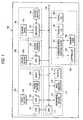
- the configuration of the video game machine 100will now be described with reference to Fig. 1.
- the video game machine 100comprises a control section 110 for controlling the operation of the overall game machine 100; an image processing section 120 for performing processing pertaining to image display; a sound processing section 130 for performing processing pertaining to sound output; an auxiliary storage control section 140 which loads a program and data from a recording medium; a communications control section 150 for controlling input and output of other data; and a main bus 160 for interconnecting the control section 110, the image processing section 120, the sound processing section 130, the auxiliary storage control section 140, and the communications control section 150.
- the control section 110comprises a CPU 111; aperipheral device controller 112; a primary storage device (main memory) 113 formed from RAM; and ROM 114.
- the peripheral device controller 112effects an interrupt control operation, a time control operation, a memory control operation, and transfer of direct memory access (DMA) .
- the ROM 114stores a program, such as an operating system (OS) for managing the main memory 113, the image processing section 120, and the sound processing section 130.
- the CPU 111controls the overall video game machine 100 by running the OS stored in the ROM 114.
- the CPU 111is equipped with an instruction cache and scratch pad memory and manages actual memory.
- the image processing section 120comprises a geometry transfer engine (GTE) 121 formed from a coordinate computation coprocessor for effecting processing, such as coordinate conversion processing; a graphics processing unit (GPU) 122 for effecting a rendering operation in accordance with a rendering instruction output from the CPU 111; a frame buffer 123 for storing an image rendered by the GPU 122; an image decoder (MDEC) 124 for decoding image data which have been encoded through orthogonal transformation, such as so-called discrete cosine transformation and compressed; and video output means 125 such as a display device.
- GTEgeometry transfer engine
- GPUgraphics processing unit
- MDECimage decoder
- the sound processing section 130comprises a sound reproduction processor (SPU) 131 for emitting sound; a sound buffer 132 for storing sound read from a CD-ROM, musical data, or sound source data; and sound output means 133, such as an amplifier and speaker for outputting sound produced by the SPU 131.
- SPUsound reproduction processor
- the auxiliary storage device control section 140comprises a CD-ROM drive unit 143 for reproducing a program or data recorded on a CD-ROM disk; a decoder 141 for decoding a program or data which are recorded along with, e.g., an error correction code (ECC) ; and a CD-ROM buffer 142 for temporarily storing reproduction data output from the CD-ROM drive unit 143.
- a CD-ROM drive unit 143for reproducing a program or data recorded on a CD-ROM disk
- a decoder 141for decoding a program or data which are recorded along with, e.g., an error correction code (ECC)
- ECCerror correction code
- the communications control section 150comprises a communications control device 151 for effecting communication control with the CPU 111 via the main bus 160; a controller 152 for entering an instruction from a user; a memory card 153 for storing settings of a game; a parallel I/O port 154 connected to a main bus 160; and an asynchronous serial I/O port 155 connected to the main bus 160.
- the OS stored in the ROM 114is run by the CPU 111.
- the image processing section 120 and the sound processing section 130are controlled under the OS.
- the OScontrols the auxiliary storage control section 140 and runs a program recorded on a CD-ROM, such as a game.
- the CPU 111controls the image processing section 120 and the sound processing section 130.
- the video output means 125displays an image
- the sound output means 133outputs sounds, such as sound effects or music.
- the video game program according to the present inventionis run by the video game machine 100 as a program to be loaded from the CD-ROM drive 143.
- the controller 152has the following switches. Orientation levers 201 and 202 input orientation commands in accordance with a direction in which these levers 201 and 202 are tilted, and these levers are used primarily for inputting orientation. Switches 203 to 212, a select switch 213, a start switch 214, and an analog/digital changeover switch 215 are press button switches. Of these switches, the start switch 214 is used primarily for activating a primary section of the video game from a menu appearing at the initiation of a video game program. The analog/digital changeover switch 215 switches to output a result of operation of the orientation levers 201 and 202 as an analog signal or a digital signal. A cable 216 connects the controller 152 to the video game machine 100.
- An action game of quarter view displayis described as an embodiment of a video game program according to the present embodiment.
- One main character A(designated by A in the drawings) and one sub-character B (designated by B in the drawings) appear as player characters in the video game.
- the main character Arequires player' s manipulation at all times . If the player performs no manipulation, the main character A does nothing.
- a screen of the video gameis always displayed at the center of the main character A.
- the playercan manipulate the sub-character B to a certain extent.
- the sub-character Bacts in accordance with a predetermined algorithm set previously in the video game program.
- opponents(designated by C1, C2, C3, and C4 in the drawings) of non-player characters appear in the game. Actions of the opponent characters are not susceptible to the player's manipulation and act in accordance with a predetermined algorithm.
- the moving direction of the main character Ais input by the orientation lever 201
- the moving direction of the sub-character Bis input by the orientation lever 202.
- Switches 203 to 207are assigned to manipulation of the main character A.
- Switches 208 to 212are assigned to manipulation of the sub-character B.
- the sub-character Bacts in accordance with the player's manipulation or a predetermined algorithm.
- a state in which the sub-character B operates in accordance with the player's manipulationis called a manual operation mode of a video game program.
- a state in which the sub-character B operates in accordance with a predetermined algorithmis called an auto operation mode of the video game program.
- the sub-character Boperates in an auto operation mode (step S1).
- the sub-character Battacks an opponent character located at the closest position .
- the sub-character Battacks an opponent character C2.
- step S2when any one of the switches assigned to the sub-character B; that is, the orientation lever 202 and the switches 206 and 207, is subjected to an input action (step S2), the video game program checks whether or not a shift to a manual operation is now available (step S3). This check is for imposing a predetermined requirement on a shift from an auto operation mode to a manual operation mode .
- the checkis made to represent in a video game a situation in which, for any reason, the sub-character B cannot follow an instruction entered by way of manual operation; for example, a frame in which the sub-character B is already engaging in battle with an opponent character and is performing attack and defense actions (e.g., is in the course of kicking the opponent with his feet), a frame in which the sub-character B cannot move because of severe injury, or a case where the action of the sub-character B is limited for reasons of a game system.
- step S3a positional relationship between the main character A and the sub-character B is verified (step S3).
- the playerIn order for the player to instruct the action of the sub-character B directly, the player needs to see the sub-character B. However, depending on the situation of the game, the sub-character B may be outside the screen. Therefore, when the sub-character B is not present on the screen, the player causes the main character B to approach the sub-character A (step S5). When the sub-character B is present in the screen, shift is made to the manual operation mode (step S6).
- the sub-character Bacts in accordance with key input performed by the player. Shift is made from the manual operation mode to the auto operation mode when none of the orientation lever 202 and the switches 206 and 207 is subjected to input operation for a predetermined period of time.
- the sub-character Battacks the closest opponent character.
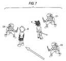
- the playermay desire to change a target. For example, in the scenario shown in Fig. 5, an opponent character C3 is approaching the main character A, who is already engaging in battle with the opponent character C1.
- an object to be attacked by the sub-character Bis originally an opponent character C2, and there may be case where the player desires to prioritize elimination of the opponent character C3.
- a numerical value which is incremented with lapse of time and is decremented when a character is attackedis set for the sub-character B.
- the sub-character Bcan perform attack when his energy has a positive value.
- the sub-character Bcan only attempt to evade attack from an opponent character. Therefore, a check is first made as to the magnitude of current energy of the sub-character B (step T1). If the energy of the sub-character B assumes a value of zero, the sub-character B performs evasive action (step T2).
- a distance between the main character A and the sub-character Bis computed (step T3).
- the sub-character Bis caused to approach the main character A (step T4).
- an opponent in areas surrounding the sub-character Bis searched (step T5). When no opponent character is present, attack is not performed, and processing is terminated.
- step T6When an opponent character is present around the main character B, a determination is made as to whether or not input has been made through the orientation lever 202 within a predetermined frame in the past (step T6). When input has been made, the opponent character, which is located in the entered direction at the time of input, is selected as a target (step T7). If no input has been made, an opponent character located closest to the sub-character B is selected as a target (step T8).
- the sub-character Bhandles the closest opponent character as a target (step T8).
- the playermomentarily tilts the orientation lever 202 toward the opponent character C3 (step S1). Shift is made to a manual operation mode after completion of an animation pertaining to attack/defense actions of the sub-character B (step S2).
- the opponent character C3 located in the direction in which the orientation lever 202 has been tiltedis set as a target.
- the sub-character Bhas positive energy (step T1) and is located sufficiently close to the main character A (step T3).
- Opponent characters C1, C2, and C3are present as opponent characters which the sub-character B can attack (step T5). Therefore, determination is made that a manual operation was performed immediately before (step T6) that is, the manual operation is available.
- the sub-character Bchanges a target and makes movement in the manner as shown in Fig. 7, thus attacking the opponent character C3.
- the above examplehas described a situation in which a video game according to the present invention can be represented, by taking as subject matter a battle between a plurality of player characters and a plurality of opponent characters.
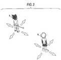
- the next examplepertains to a battle between a plurality of player characters and a single opponent character (Fig. 8).
- the opponent character Chas a characteristic of completely preventing a frontal attack and being not susceptible to damage at all (Fig. 9). For this reason, the main character A cannot defeat the opponent character C.
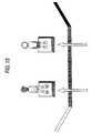
- the playermove the sub-character B in the direction designated by the arrow B shown in Fig. 10 in a manual operation mode while causing the main character A to continually attack. By this action, the sub-character B can impart damage to the opponent character C (Fig. 11).
- the switches D1 and D2 being turned on simultaneouslymay be added to requirements for opening the door. In this case, a difficulty level of operation required for playing a game can be increased.
- two or more sub-characters Bmay be employed.
- the present inventionis described with reference to an example in which player characters battle with non-player characters.
- the present inventioncan be applied to a system by way of which a plurality of players cause player characters to battle with each other.
- a video game program and a video game machineare provided with different orientation input means assigned to respective player characters.
- switches assigned to the player characterare operated in their present forms. Therefore, there is no necessity for the player to perform special operation for only switching purpose. Hence, the player can manipulate the sub-character without consideration of switching between operation modes.
- the video game program and the video game machineenable simultaneous manipulation of a plurality of player characters, a challenge ⁇ which can be met only when a plurality of player characters are manipulated simultaneously ⁇ can be set in a game.
- a sub-characterautomatically takes a specified opponent character as a target.
- semi-automatic control of the sub-charactercan be effected.
Landscapes
- Engineering & Computer Science (AREA)
- Multimedia (AREA)
- Human Computer Interaction (AREA)
- Processing Or Creating Images (AREA)
- Closed-Circuit Television Systems (AREA)
Abstract
Description
Claims (21)
- A video game machine comprising:wherein at least one of the plurality of player charactershas a first mode in which the player character operates inaccordance with input made by the switches assigned to theplayer character, and a second mode in which the playercharacter operates in accordance with a predeterminedsub-program, anda controller provided with a plurality of switchesincluding a plurality of orientation input means;means for simultaneously displaying a plurality ofplayer characters; andmeans of assigning switches including at least one ofthe orientation input means to the respective playercharacters,
wherein switching between the first and second modesis effected when input operation, by any one of switchesassigned to the player characters, is performed. - The video game machine according to claim 1, whereinthe sub-program takes, as an object of action, a non-playercharacter located at a position closest to the player characterwhich is an object of control.
- The video game machine according to claim 1 or 2, wherein
in the first mode, a non-player character located ina direction which is entered by the orientation input meansassigned to the player character is detected, and
in the second mode, the detected non-player characteris taken as an object of action for the player character. - The video game machine according to any one of claims1 through 3, wherein a non-player character takes one of theplurality of player characters located closest to thenon-player character as an object of action.
- The video game machine according to any one of claims2 through 4, wherein the action includes one of approachingaction, battle action and conversation of the non-playercharacter.
- The video game machine according to any one of claims1 through 5, wherein at least one of the plurality of playercharacters acts in accordance with only an input entered bythe assigned switches.
- The video game machine according to any one of claims1 through 6, wherein anon-player character completely preventsattack in one direction.
- The video game machine according to any one of claims1 through 7, wherein
a plurality of switches which are to be actuated by theplayer character are provided, and
when the plurality of player characters simultaneouslyactuates the plurality of switches, a predetermined responseis performed. - The video game machine according to claim 8, whereinthe plurality of switches includes a plurality of switcheswhich are turned on when the player characters step on theswitches.
- A method of controlling action of a player characterwhich appears in a video game program to be executed by a videogame machine which enables connection of a controller havinga plurality of orientation input means, the method comprisingthe steps of:wherein at least one of the plurality of player charactershas a first mode in which the player character operates inaccordance with inputs made by the switches assigned to the player character, and a second mode in which the playercharacter operates in accordance with a predeterminedsub-program; andsimultaneously displaying a plurality of playercharacters; andassigning switches including at least one of theorientation input means to the respective player characters,
switching the first and second modes when input operationby way of any one of switches assigned to the player characteris performed. - A computer readable medium storing a video game programto be executed by a video game machine which enables connectionof a controller having a plurality of orientation input means,the method comprising the steps of:whereinsimultaneously displaying a plurality of playercharacters; andassigning switches including at least one of theorientation input means to the respective player characters,
at least one of the plurality of player characters hasa first mode in which the player character operates inaccordance with inputs made by the switches assigned to theplayer character, and a second mode in which the playercharacter operates in accordance with a predeterminedsub-program; and
switching between the first and second modes when inputoperation is performed by any one of switches assigned to theplayer characters. - A computer readable medium according to claim 11, whereinthe sub-program takes, as an object of action, a non-playercharacter located at a position closest to the player characterwhich is an object of control.
- The computer readable medium according to claim 11 or12, wherein
in the first mode, a non-player character located ina direction which is entered by the orientation input meansassigned to the player character is detected, and
in the second mode, the detected non-player characteris taken as an object of action for the player character. - The computer readable medium according to any one ofclaims 11 through 13, wherein a non-player character takesone of the player characters located closest to the non-playercharacter as an object of action.
- The computer readable medium according to any one ofclaims 12 through 14, wherein the action includes one ofapproaching action, battle action and conversation of thenon-player character.
- The computer readable medium according to any one of claims 11 through 15, wherein at least one of the pluralityof player characters acts in accordance with only an inputentered by the assigned switches.
- The computer readable medium according to any one ofclaims 11 through 16, wherein anon-player character completelyprevents attack in one direction.
- The computer readable medium according to any one ofclaims 11 through 17, wherein
a plurality of switches which are to be actuated by theplayer character are provided, and
when the plurality of player characters simultaneouslyactuates the plurality of switches, a predetermined responseis performed. - The computer readable medium according to claim 18,wherein the plurality of switches includes a plurality ofswitches which are turned on when the player characters stepon the switches.
- A video game machine which operates in accordance witha video game program as defined in any one of claims 11 through19.
- The video game machine according to claim 20, furthercomprising a controller having apluralityof orientation inputmeans.
Applications Claiming Priority (2)
| Application Number | Priority Date | Filing Date | Title |
|---|---|---|---|
| JP2001021697AJP2002224435A (en) | 2001-01-30 | 2001-01-30 | Video game device, method for controlling behavior of player character and video game program |
| JP2001021697 | 2001-01-30 |
Publications (3)
| Publication Number | Publication Date |
|---|---|
| EP1228794A2true EP1228794A2 (en) | 2002-08-07 |
| EP1228794A3 EP1228794A3 (en) | 2003-09-24 |
| EP1228794B1 EP1228794B1 (en) | 2008-09-17 |
Family
ID=18887214
Family Applications (1)
| Application Number | Title | Priority Date | Filing Date |
|---|---|---|---|
| EP02250507AExpired - LifetimeEP1228794B1 (en) | 2001-01-30 | 2002-01-25 | Video game machine, player character action control method, and video game program |
Country Status (4)
| Country | Link |
|---|---|
| US (1) | US6743099B2 (en) |
| EP (1) | EP1228794B1 (en) |
| JP (1) | JP2002224435A (en) |
| DE (1) | DE60228901D1 (en) |
Cited By (17)
| Publication number | Priority date | Publication date | Assignee | Title |
|---|---|---|---|---|
| US20100029371A1 (en)* | 2008-08-01 | 2010-02-04 | Gennady Medvinsky | Personal Game Services Commerce System (PGSCS) |
| EP1852163A3 (en)* | 2006-05-01 | 2011-05-25 | Nintendo Co., Ltd. | Game program and game apparatus |
| EP2545971A3 (en)* | 2011-03-31 | 2013-03-06 | Konami Digital Entertainment Co., Ltd. | Game device, game device control method, program, and information storage medium |
| US8439733B2 (en) | 2007-06-14 | 2013-05-14 | Harmonix Music Systems, Inc. | Systems and methods for reinstating a player within a rhythm-action game |
| US8444464B2 (en) | 2010-06-11 | 2013-05-21 | Harmonix Music Systems, Inc. | Prompting a player of a dance game |
| US8449360B2 (en) | 2009-05-29 | 2013-05-28 | Harmonix Music Systems, Inc. | Displaying song lyrics and vocal cues |
| US8465366B2 (en) | 2009-05-29 | 2013-06-18 | Harmonix Music Systems, Inc. | Biasing a musical performance input to a part |
| US8550908B2 (en) | 2010-03-16 | 2013-10-08 | Harmonix Music Systems, Inc. | Simulating musical instruments |
| US8663013B2 (en) | 2008-07-08 | 2014-03-04 | Harmonix Music Systems, Inc. | Systems and methods for simulating a rock band experience |
| US8678896B2 (en) | 2007-06-14 | 2014-03-25 | Harmonix Music Systems, Inc. | Systems and methods for asynchronous band interaction in a rhythm action game |
| US8686269B2 (en) | 2006-03-29 | 2014-04-01 | Harmonix Music Systems, Inc. | Providing realistic interaction to a player of a music-based video game |
| US8702485B2 (en) | 2010-06-11 | 2014-04-22 | Harmonix Music Systems, Inc. | Dance game and tutorial |
| US9024166B2 (en) | 2010-09-09 | 2015-05-05 | Harmonix Music Systems, Inc. | Preventing subtractive track separation |
| US9358456B1 (en) | 2010-06-11 | 2016-06-07 | Harmonix Music Systems, Inc. | Dance competition game |
| WO2017171567A1 (en)* | 2016-03-30 | 2017-10-05 | Bloober Team S.A. | The method of simultaneous playing in single-player video games |
| US9981193B2 (en) | 2009-10-27 | 2018-05-29 | Harmonix Music Systems, Inc. | Movement based recognition and evaluation |
| US10357714B2 (en) | 2009-10-27 | 2019-07-23 | Harmonix Music Systems, Inc. | Gesture-based user interface for navigating a menu |
Families Citing this family (32)
| Publication number | Priority date | Publication date | Assignee | Title |
|---|---|---|---|---|
| US7452279B2 (en)* | 2001-08-09 | 2008-11-18 | Kabushiki Kaisha Sega | Recording medium of game program and game device using card |
| US7198568B2 (en)* | 2002-05-01 | 2007-04-03 | Nintendo Co., Ltd. | Game machine and game program for changing the movement of one character based on the movement of another character |
| US20050003877A1 (en)* | 2003-05-09 | 2005-01-06 | Electronic Arts Inc. | Systems and methods for playmaker control |
| JP3732843B2 (en)* | 2004-02-18 | 2006-01-11 | 株式会社スクウェア・エニックス | Video game device program and video game device |
| JP4117264B2 (en) | 2004-04-16 | 2008-07-16 | 任天堂株式会社 | Puzzle game apparatus and puzzle game program |
| JP2006043345A (en)* | 2004-08-09 | 2006-02-16 | Aruze Corp | Game system |
| JP4625968B2 (en)* | 2004-11-10 | 2011-02-02 | 株式会社セガ | Network game system and game device |
| JP4137128B2 (en)* | 2006-01-25 | 2008-08-20 | 株式会社スクウェア・エニックス | Video game processing apparatus, video game processing method, and video game processing program |
| WO2007103312A2 (en)* | 2006-03-07 | 2007-09-13 | Goma Systems Corp. | User interface for controlling virtual characters |
| JP4671196B2 (en) | 2006-10-31 | 2011-04-13 | 株式会社スクウェア・エニックス | NETWORK GAME SYSTEM, NETWORK GAME TERMINAL DEVICE, GAME SCREEN DISPLAY METHOD, PROGRAM, AND RECORDING MEDIUM |
| JP2008125617A (en)* | 2006-11-17 | 2008-06-05 | Sega Corp | GAME DEVICE AND GAME PROGRAM |
| JP4128595B2 (en)* | 2006-11-29 | 2008-07-30 | 株式会社スクウェア・エニックス | GAME DEVICE, GAME PROGRESSING METHOD, PROGRAM, AND RECORDING MEDIUM |
| US9536344B1 (en) | 2007-11-30 | 2017-01-03 | Roblox Corporation | Automatic decoration of a three-dimensional model |
| JP4545809B2 (en)* | 2008-06-05 | 2010-09-15 | 株式会社スクウェア・エニックス | GAME DEVICE AND PROGRAM |
| JP4773492B2 (en)* | 2008-09-12 | 2011-09-14 | 任天堂株式会社 | GAME DEVICE AND GAME PROGRAM |
| US9248376B2 (en)* | 2008-09-30 | 2016-02-02 | Nintendo Co., Ltd. | Computer-readable storage medium having stored game program therein, and game apparatus |
| US8403753B2 (en)* | 2008-09-30 | 2013-03-26 | Nintendo Co., Ltd. | Computer-readable storage medium storing game program, game apparatus, and processing method |
| JP5999829B2 (en)* | 2009-05-28 | 2016-09-28 | 任天堂株式会社 | GAME PROGRAM AND GAME DEVICE |
| JP5730430B1 (en)* | 2014-06-27 | 2015-06-10 | ガンホー・オンライン・エンターテイメント株式会社 | Game terminal device |
| JP6378224B2 (en)* | 2016-02-26 | 2018-08-22 | グリー株式会社 | Control program, control method, and information processing apparatus |
| JP6872890B2 (en)* | 2016-11-21 | 2021-05-19 | 株式会社コーエーテクモゲームス | Game program, recording medium, game processing method |
| JP6831681B2 (en)* | 2016-11-30 | 2021-02-17 | グリー株式会社 | Control programs, control methods and information processing equipment |
| JP7043307B2 (en)* | 2018-03-23 | 2022-03-29 | 株式会社コーエーテクモゲームス | Game programs and storage media |
| US11045735B2 (en)* | 2018-09-14 | 2021-06-29 | Bandai Namco Entertainment Inc. | Computer system |
| JP6621553B1 (en)* | 2019-01-31 | 2019-12-18 | 株式会社Cygames | Information processing program, information processing method, and information processing apparatus |
| JP7034966B2 (en)* | 2019-02-13 | 2022-03-14 | 任天堂株式会社 | Game programs, information processing systems, information processing devices and game control methods |
| JP7173927B2 (en)* | 2019-06-04 | 2022-11-16 | 任天堂株式会社 | Game system, game program, information processing device, and game processing method |
| JP6985334B2 (en)* | 2019-06-26 | 2021-12-22 | 株式会社スクウェア・エニックス | Game processing programs, methods and information processing equipment |
| JP7233399B2 (en)* | 2020-06-23 | 2023-03-06 | 任天堂株式会社 | GAME PROGRAM, GAME DEVICE, GAME SYSTEM, AND GAME PROCESSING METHOD |
| CN113181650B (en)* | 2021-05-31 | 2023-04-25 | 腾讯科技(深圳)有限公司 | Control method, device, equipment and storage medium for calling object in virtual scene |
| US11484793B1 (en)* | 2021-09-02 | 2022-11-01 | Supercell Oy | Game control |
| JP7503185B2 (en)* | 2022-10-18 | 2024-06-19 | 任天堂株式会社 | GAME PROGRAM, GAME SYSTEM, GAME DEVICE, AND GAME CONTROL METHOD |
Family Cites Families (8)
| Publication number | Priority date | Publication date | Assignee | Title |
|---|---|---|---|---|
| JP3181808B2 (en) | 1995-04-17 | 2001-07-03 | 株式会社スクウェア | Video game apparatus, control method thereof, and control device |
| TW353171B (en)* | 1995-05-10 | 1999-02-21 | Nintendo Co Ltd | Manipulator provided with an analog joy stick |
| TW469148B (en)* | 1996-10-09 | 2001-12-21 | Sega Enterprises Kk | Game apparatus, method of game processing, game execution method, and game system |
| JP3072343B2 (en)* | 1997-05-02 | 2000-07-31 | コナミ株式会社 | Video game machine, image processing method for video game machine, and recording medium recording computer program |
| US6428411B1 (en)* | 1997-05-02 | 2002-08-06 | Konami Co., Ltd. | Volleyball video game system |
| JP2000084242A (en)* | 1998-09-14 | 2000-03-28 | Taito Corp | Shooting game device |
| JP2000308759A (en)* | 1999-04-27 | 2000-11-07 | Konami Co Ltd | Control method for video game characters, video game device, and storage medium |
| JP2000325660A (en)* | 1999-05-24 | 2000-11-28 | Namco Ltd | Game system and information storage medium |
- 2001
- 2001-01-30JPJP2001021697Apatent/JP2002224435A/enactivePending
- 2002
- 2002-01-25DEDE60228901Tpatent/DE60228901D1/ennot_activeExpired - Lifetime
- 2002-01-25EPEP02250507Apatent/EP1228794B1/ennot_activeExpired - Lifetime
- 2002-01-29USUS10/051,978patent/US6743099B2/ennot_activeExpired - Fee Related
Cited By (32)
| Publication number | Priority date | Publication date | Assignee | Title |
|---|---|---|---|---|
| US8727879B2 (en) | 2006-01-05 | 2014-05-20 | Nintendo Co., Ltd. | Video game with dual motion controllers |
| US8686269B2 (en) | 2006-03-29 | 2014-04-01 | Harmonix Music Systems, Inc. | Providing realistic interaction to a player of a music-based video game |
| US8535155B2 (en) | 2006-05-01 | 2013-09-17 | Nintendo Co., Ltd. | Video game using dual motion sensing controllers |
| US9733702B2 (en) | 2006-05-01 | 2017-08-15 | Nintendo Co., Ltd. | Video game using dual motion sensing controllers |
| EP1852163A3 (en)* | 2006-05-01 | 2011-05-25 | Nintendo Co., Ltd. | Game program and game apparatus |
| US10065108B2 (en) | 2006-05-01 | 2018-09-04 | Nintendo Co., Ltd. | Video game using dual motion sensing controllers |
| US9278280B2 (en) | 2006-05-01 | 2016-03-08 | Nintendo Co., Ltd. | Video game using dual motion sensing controllers |
| US8444486B2 (en) | 2007-06-14 | 2013-05-21 | Harmonix Music Systems, Inc. | Systems and methods for indicating input actions in a rhythm-action game |
| US8690670B2 (en) | 2007-06-14 | 2014-04-08 | Harmonix Music Systems, Inc. | Systems and methods for simulating a rock band experience |
| US8439733B2 (en) | 2007-06-14 | 2013-05-14 | Harmonix Music Systems, Inc. | Systems and methods for reinstating a player within a rhythm-action game |
| US8678895B2 (en) | 2007-06-14 | 2014-03-25 | Harmonix Music Systems, Inc. | Systems and methods for online band matching in a rhythm action game |
| US8678896B2 (en) | 2007-06-14 | 2014-03-25 | Harmonix Music Systems, Inc. | Systems and methods for asynchronous band interaction in a rhythm action game |
| US8663013B2 (en) | 2008-07-08 | 2014-03-04 | Harmonix Music Systems, Inc. | Systems and methods for simulating a rock band experience |
| US20100029371A1 (en)* | 2008-08-01 | 2010-02-04 | Gennady Medvinsky | Personal Game Services Commerce System (PGSCS) |
| US8465366B2 (en) | 2009-05-29 | 2013-06-18 | Harmonix Music Systems, Inc. | Biasing a musical performance input to a part |
| US8449360B2 (en) | 2009-05-29 | 2013-05-28 | Harmonix Music Systems, Inc. | Displaying song lyrics and vocal cues |
| US10357714B2 (en) | 2009-10-27 | 2019-07-23 | Harmonix Music Systems, Inc. | Gesture-based user interface for navigating a menu |
| US9981193B2 (en) | 2009-10-27 | 2018-05-29 | Harmonix Music Systems, Inc. | Movement based recognition and evaluation |
| US10421013B2 (en) | 2009-10-27 | 2019-09-24 | Harmonix Music Systems, Inc. | Gesture-based user interface |
| US8636572B2 (en) | 2010-03-16 | 2014-01-28 | Harmonix Music Systems, Inc. | Simulating musical instruments |
| US8568234B2 (en) | 2010-03-16 | 2013-10-29 | Harmonix Music Systems, Inc. | Simulating musical instruments |
| US8550908B2 (en) | 2010-03-16 | 2013-10-08 | Harmonix Music Systems, Inc. | Simulating musical instruments |
| US8874243B2 (en) | 2010-03-16 | 2014-10-28 | Harmonix Music Systems, Inc. | Simulating musical instruments |
| US9278286B2 (en) | 2010-03-16 | 2016-03-08 | Harmonix Music Systems, Inc. | Simulating musical instruments |
| US8562403B2 (en) | 2010-06-11 | 2013-10-22 | Harmonix Music Systems, Inc. | Prompting a player of a dance game |
| US8702485B2 (en) | 2010-06-11 | 2014-04-22 | Harmonix Music Systems, Inc. | Dance game and tutorial |
| US9358456B1 (en) | 2010-06-11 | 2016-06-07 | Harmonix Music Systems, Inc. | Dance competition game |
| US8444464B2 (en) | 2010-06-11 | 2013-05-21 | Harmonix Music Systems, Inc. | Prompting a player of a dance game |
| US9024166B2 (en) | 2010-09-09 | 2015-05-05 | Harmonix Music Systems, Inc. | Preventing subtractive track separation |
| EP2545971A3 (en)* | 2011-03-31 | 2013-03-06 | Konami Digital Entertainment Co., Ltd. | Game device, game device control method, program, and information storage medium |
| WO2017171567A1 (en)* | 2016-03-30 | 2017-10-05 | Bloober Team S.A. | The method of simultaneous playing in single-player video games |
| US10500488B2 (en) | 2016-03-30 | 2019-12-10 | Bloober Team S.A. | Method of simultaneous playing in single-player video games |
Also Published As
| Publication number | Publication date |
|---|---|
| EP1228794A3 (en) | 2003-09-24 |
| US6743099B2 (en) | 2004-06-01 |
| DE60228901D1 (en) | 2008-10-30 |
| US20020119811A1 (en) | 2002-08-29 |
| EP1228794B1 (en) | 2008-09-17 |
| JP2002224435A (en) | 2002-08-13 |
Similar Documents
| Publication | Publication Date | Title |
|---|---|---|
| US6743099B2 (en) | Video game machine, player character action control method, and video game program | |
| KR100743128B1 (en) | Image processing method, video game device and recording medium | |
| US6488586B1 (en) | Recording medium and entertainment system | |
| US8317579B2 (en) | Game apparatus and program | |
| US6666764B1 (en) | Method of controlling a character in a video game | |
| US7927202B2 (en) | Video game processing apparatus, a method and a computer program product for processing a video game | |
| JP3126944B2 (en) | Video game system and computer-readable recording medium on which program for executing the game is recorded | |
| US6273814B1 (en) | Game apparatus and method for controlling timing for executive action by game character | |
| US7559835B2 (en) | Video game processing apparatus, a method and a computer program product for processing a video game | |
| US6544119B2 (en) | Method, video game device, and program for controlling game | |
| JP3145064B2 (en) | Video game machine and medium recording video game program | |
| US6676519B2 (en) | Video game including character capability setting | |
| JP2001029655A (en) | Action selection support system, recording medium and game device | |
| US7467998B2 (en) | Puzzle game apparatus, storage medium storing puzzle game program, and puzzle game controlling method | |
| JP2000132705A (en) | Image processor, image processing method, game device and recording medium | |
| JP2000126446A (en) | Game device, storing of game item, and data recording medium | |
| JP2000189669A (en) | GAME DEVICE, CHARACTER OPERATION CONTROL METHOD IN GAME DEVICE, AND MACHINE-READABLE RECORDING MEDIUM | |
| JP2000037562A (en) | Game apparatus and information memory medium | |
| JP2000157735A (en) | Game device, icon registration method, and recording medium | |
| JP2000126448A (en) | Game device, decision of character's action, and mechanically readable data recording medium in which program is recorded | |
| KR20080080679A (en) | Video game program, video game device and video game control method | |
| US6296567B1 (en) | Video game machine and computer-readable recording medium containing video game program | |
| JP2000189673A (en) | Game device, behavior parameter changing method, and recording medium | |
| JP4010682B2 (en) | GAME SYSTEM AND INFORMATION STORAGE MEDIUM | |
| JP2000176152A (en) | Game device, game control method, and its storage medium |
Legal Events
| Date | Code | Title | Description |
|---|---|---|---|
| PUAI | Public reference made under article 153(3) epc to a published international application that has entered the european phase | Free format text:ORIGINAL CODE: 0009012 | |
| AK | Designated contracting states | Kind code of ref document:A2 Designated state(s):AT BE CH CY DE DK ES FI FR GB GR IE IT LI LU MC NL PT SE TR | |
| AX | Request for extension of the european patent | Free format text:AL;LT;LV;MK;RO;SI | |
| RAP1 | Party data changed (applicant data changed or rights of an application transferred) | Owner name:KONAMI CORPORATION | |
| PUAL | Search report despatched | Free format text:ORIGINAL CODE: 0009013 | |
| AK | Designated contracting states | Kind code of ref document:A3 Designated state(s):AT BE CH CY DE DK ES FI FR GB GR IE IT LI LU MC NL PT SE TR | |
| AX | Request for extension of the european patent | Extension state:AL LT LV MK RO SI | |
| 17P | Request for examination filed | Effective date:20040311 | |
| AKX | Designation fees paid | Designated state(s):DE FR GB | |
| GRAP | Despatch of communication of intention to grant a patent | Free format text:ORIGINAL CODE: EPIDOSNIGR1 | |
| GRAS | Grant fee paid | Free format text:ORIGINAL CODE: EPIDOSNIGR3 | |
| GRAA | (expected) grant | Free format text:ORIGINAL CODE: 0009210 | |
| AK | Designated contracting states | Kind code of ref document:B1 Designated state(s):DE FR GB | |
| REG | Reference to a national code | Ref country code:GB Ref legal event code:FG4D | |
| REF | Corresponds to: | Ref document number:60228901 Country of ref document:DE Date of ref document:20081030 Kind code of ref document:P | |
| PLBE | No opposition filed within time limit | Free format text:ORIGINAL CODE: 0009261 | |
| STAA | Information on the status of an ep patent application or granted ep patent | Free format text:STATUS: NO OPPOSITION FILED WITHIN TIME LIMIT | |
| 26N | No opposition filed | Effective date:20090618 | |
| PGFP | Annual fee paid to national office [announced via postgrant information from national office to epo] | Ref country code:DE Payment date:20130122 Year of fee payment:12 Ref country code:GB Payment date:20130122 Year of fee payment:12 Ref country code:FR Payment date:20130213 Year of fee payment:12 | |
| REG | Reference to a national code | Ref country code:DE Ref legal event code:R119 Ref document number:60228901 Country of ref document:DE | |
| GBPC | Gb: european patent ceased through non-payment of renewal fee | Effective date:20140125 | |
| REG | Reference to a national code | Ref country code:DE Ref legal event code:R119 Ref document number:60228901 Country of ref document:DE Effective date:20140801 | |
| PG25 | Lapsed in a contracting state [announced via postgrant information from national office to epo] | Ref country code:DE Free format text:LAPSE BECAUSE OF NON-PAYMENT OF DUE FEES Effective date:20140801 | |
| REG | Reference to a national code | Ref country code:FR Ref legal event code:ST Effective date:20140930 | |
| PG25 | Lapsed in a contracting state [announced via postgrant information from national office to epo] | Ref country code:GB Free format text:LAPSE BECAUSE OF NON-PAYMENT OF DUE FEES Effective date:20140125 Ref country code:FR Free format text:LAPSE BECAUSE OF NON-PAYMENT OF DUE FEES Effective date:20140131 |