EP1228413B1 - Sleep state transitioning - Google Patents
Sleep state transitioningDownload PDFInfo
- Publication number
- EP1228413B1 EP1228413B1EP00992954AEP00992954AEP1228413B1EP 1228413 B1EP1228413 B1EP 1228413B1EP 00992954 AEP00992954 AEP 00992954AEP 00992954 AEP00992954 AEP 00992954AEP 1228413 B1EP1228413 B1EP 1228413B1
- Authority
- EP
- European Patent Office
- Prior art keywords
- software
- processor
- memory
- state
- main memory
- Prior art date
- Legal status (The legal status is an assumption and is not a legal conclusion. Google has not performed a legal analysis and makes no representation as to the accuracy of the status listed.)
- Expired - Lifetime
Links
Images


Classifications
- G—PHYSICS
- G06—COMPUTING OR CALCULATING; COUNTING
- G06F—ELECTRIC DIGITAL DATA PROCESSING
- G06F1/00—Details not covered by groups G06F3/00 - G06F13/00 and G06F21/00
- G06F1/26—Power supply means, e.g. regulation thereof
- G06F1/32—Means for saving power
- G06F1/3203—Power management, i.e. event-based initiation of a power-saving mode
- G06F1/3234—Power saving characterised by the action undertaken
- G06F1/3237—Power saving characterised by the action undertaken by disabling clock generation or distribution
- G—PHYSICS
- G06—COMPUTING OR CALCULATING; COUNTING
- G06F—ELECTRIC DIGITAL DATA PROCESSING
- G06F1/00—Details not covered by groups G06F3/00 - G06F13/00 and G06F21/00
- G06F1/26—Power supply means, e.g. regulation thereof
- G06F1/32—Means for saving power
- G06F1/3203—Power management, i.e. event-based initiation of a power-saving mode
- G06F1/3234—Power saving characterised by the action undertaken
- G06F1/3287—Power saving characterised by the action undertaken by switching off individual functional units in the computer system
- G—PHYSICS
- G06—COMPUTING OR CALCULATING; COUNTING
- G06F—ELECTRIC DIGITAL DATA PROCESSING
- G06F9/00—Arrangements for program control, e.g. control units
- G06F9/06—Arrangements for program control, e.g. control units using stored programs, i.e. using an internal store of processing equipment to receive or retain programs
- G06F9/44—Arrangements for executing specific programs
- G06F9/4401—Bootstrapping
- G06F9/4418—Suspend and resume; Hibernate and awake
- Y—GENERAL TAGGING OF NEW TECHNOLOGICAL DEVELOPMENTS; GENERAL TAGGING OF CROSS-SECTIONAL TECHNOLOGIES SPANNING OVER SEVERAL SECTIONS OF THE IPC; TECHNICAL SUBJECTS COVERED BY FORMER USPC CROSS-REFERENCE ART COLLECTIONS [XRACs] AND DIGESTS
- Y02—TECHNOLOGIES OR APPLICATIONS FOR MITIGATION OR ADAPTATION AGAINST CLIMATE CHANGE
- Y02D—CLIMATE CHANGE MITIGATION TECHNOLOGIES IN INFORMATION AND COMMUNICATION TECHNOLOGIES [ICT], I.E. INFORMATION AND COMMUNICATION TECHNOLOGIES AIMING AT THE REDUCTION OF THEIR OWN ENERGY USE
- Y02D10/00—Energy efficient computing, e.g. low power processors, power management or thermal management
Definitions
- This inventionrelates to sleep state transitioning.
- ACPIAdvanced Configuration and Power Interface Specification
- RAM subsystemscan also have low power states.
- a memory controllercommunicates with the memory chips using a particular protocol.
- the memory controlleris an intelligent device that is initialized before it begins the normal operation of reading data from and writing data to the memory chips.
- the memory controllerincludes a RAMBUS ASIC Cell ("RAC") that controls the electrical interface to the memory chips, performs multiplexing and demultiplexing functions, and converts data between a high speed proprietary serialized interface to the memory chips and the lower speed parallel interface used by the processor.
- the RDRAM subsystemcan be powered down to conserve power. The RDRAM subsystem must be reinstalled after being powered down.
- US 5,931,951 Adiscloses a computer system comprising a CPU, a host/PCl bridging device, a main memory, a secondary cache L2 and a BIOS ROM.
- the L2 cache with the power- down input terminalis also switched to the sleep mode simultaneously.
- the computer systemenables ganged control of CPU power saving and cache power saving by simply adding a register control procedure to a conventional BIOS program that implements a power saving function involving stopping of the CPU.
- an external interruptoccurs to the CPU, the CPU leaves the sleep mode and restarts run from the instruction following the Halt instruction in the power saving routine in the system management program, whereby the L2 cache is returned to the enabled state.
- a preferred embodiment of the inventionresides a system with multiple states, including an awake state and a sleep state having a processor, a memory subsystem including a memory controller and memory devices, and a second memory.
- the systemuses software stored in the second memory to initialise the memory controller upon a transition from a sleep state to an awake state.
- the systemdetects a wake event trigger, and in response to the wake event trigger, executes software out of the first memory after the initialisation.
- the memory subsystemis RAM based and stores some or an of the operating system software.
- the software that initialises the memory controlleris stored in the BIOS storage device. Prior to transitioning from an awake state to a sleep state, the operating system controls the preparation for the transition.
- a processor 10is connected to a memory controller hub 20.
- the processormay be a Pentium II ® dessert processor other general purpose processor, or dedicated controller.
- the processormay be part of a worn station, desktop personal computer, portable computer, or telecommunications, video, or graphics device.
- Memory controller hub 20is connected to and control main memory 30.
- Memory controller hub 20also handles graphics traffic and traffic to and from the 1/O controller hub.
- Main memory 30can be, for example, a RAMBUS memory system including multiple memory modules, each holding RDRAM memory chips. The individual modules can be of a comparable size to standard dual inline memory modules.
- the memory controller hub 20interacts with main memory 30 using a packetized protocol.
- the memory controlleracts as an interpreter between the RAM bus and processor 10 so that the processor does to need to concern itself with the details of the RAM structure or operation.
- Other high speed RAM technologies using a memory controller to access main memorymay be used as well.
- Memory controller hub 20 and main memory 30are clocked by memory clock 40.
- main memorymay be differentially clocked at 400 MHZ using dual phase docking to provide an effective clock rate of 800 MHZ
- the processoris clocked by processor clock 50.
- nonvolatile memory 60Also coupled to processor 10 via I/O controller hub 55 is nonvolatile memory 60.
- the nonvolatile memory 60may be ROM, EPROM, EEPROM, battery-backed RAM, and the like.
- the nonvolatile memory 60stores the BIOS (basic input/output software) and may include SMM (system management mode software). The SMM may also reside in the main memory.
- the nonvolatile memory 60stores the initialization software 70 used to initialize memory controller hub 20.
- Initialization software 70may be part of the BIOS or part of the SMM software, if present. In some applications, the initialization software may be independent of the BIOS, for example, in systems that do not have BIOS software external to processor 10.
- Memory controller hub 20includes internal registers 90 that control the address space mapping ("PAM registers"). These registers control whether the address generator looks to nonvolatile memory 60 for instructions and data or looks to main memory 30. Alternately, the PAM registers may reside in I/O controller hub 55 or in a separate well in the processor such that power is not lost when processor 10 is powered down. Connected to processor 10 is display or graphics controller 95.
- Processor 10may include cache 110 to speed up memory access time.
- the cachemay be internal to the processor chip or package and may also be external.
- I/O controller 55contains a wake trigger state machine 100 to process wake event triggers received from outside the processor. State machine 100 can also reside in memory controller hub 20 or processor 10. This state machine enables the processor to respond to wake events at a time before any software begins to execute.
- memory controller hub 20is initialized, portions of operating system 80 are loaded into main memory 30, and the system is in normal operation.
- the operating systemmay determine that power should be conserved and that the system should enter a sleep state. This determination may be triggered based on an innumerable host of factors, such as a system idle time out, a request from a user, a request from a hardware device, such as a low battery or high temperature indication, or a request from an applications program.
- step 200the operating system prepares for the transition. This preparation may include housekeeping tasks, cache flushing, context saving, and the like.
- the operating systemmay also determine which devices are to be placed in a "seep" state. In circumstances where a system is designed to maximize power savings, the entire system may be placed in a sleep state. In more simple designs, only the processor and the memory subsystem may be placed in a sleep state, while peripherals are left either fully powered or turned off.
- the operating systemalso selects the desired sleep state and sets the appropriate bit or bits in a sleep state register. For example, the ACPI specification includes the S1 and S2 sleep states that provide for a low latency return to the awake state.
- step 210the processor transitions to the sleep state.
- One way to accomplish this transitionis to set the appropriate bits in a sleep enable register. Either a software or hardware process then detects that this bit is set and asserts a sleep signal to the appropriate components.
- Processor clock 50is powered down. Powering down may be accomplished by disconnecting power from the device itself, or may be accomplished by electrically disconnecting the incoming signal from the internal distribution lines internal to each chip. For example, processor clock 50 may be left running, but the processor may electrically disconnect the incoming clock signal so the processor's internal components are not being clocked. Likewise, individual devices may be powered down with circuitry internal to the devices that prevent the flow of power to some or all of the components inside the device.
- memory controller hub 20, main memory 30, and memory clock 40are powered down.
- main memoryWhen the main memory is power down, its contents are not lost, but the main memory devices transition to a power down state that consumes very little power.
- An internal self refresh mechanism within main memory 30keeps the memory contents when main memory is powered down.
- memory clock 40transitions to a low power state. In the low power state, physical power may or may not be removed.
- a wake event triggeris detected. This trigger signals that processor 10 should resume normal operation. In some applications, this may be a return to full speed, full power mode. In other applications, the system may awaken to a more drowsy state where processor 10 may not be running at full speed.
- the wake event triggermay be generated by a source outside the system itself, such as a user pressing a "power on” or “resume” key, an incoming call signal from a modem or other telephony receiver, or it may be generated by a timer tied to a particular time of day or some other event such as scheduled system maintenance.
- the systemIn response to the detected wake event trigger, the system initializes the memory controller in step 230.
- thisincludes initializing the RAC and the RDRAM core.
- Other functions performed during initializationmay be recalibration of the RAM bus drivers, synchronization of the RAM bus clock, and a general reset of the memory controller. This initialization is not performed exclusively by the hardware, but rather involves executing initialization software 70 from nonvolatile memory 60.
- step 240control is passed in step 240 from the initialization software 70 to operating system 80 stored in main memory 30.
- Operating system 80now processes the wake event trigger. This processing can include restoring the processor context, performing a quick system diagnostic, or other routine typically executed following a wake event.
- Figure 3shows an embodiment implementing the S1 sleep state with RDRAM.
- setting the sleep enable bitwill cause the processor to transition to the S1 sleep state.
- the system management mode softwareis used to mediate between the sleep state and the RDRAM.
- a portion of the system management mode softwareis stored in nonvolatile memory 60 that also stores the BIOS (the BIOS storage device).
- BIOSthe BIOS storage device.
- the system management mode softwareis inaccessible to the operating system. The operating system has no means by which it can directly jump to routines within the system management mode software.
- the processoris configured to respond to a sleep trigger with a system management interrupt (SMI).
- SMIsystem management interrupt
- the operating systemwrites a bit to a register in step 300.
- This registertells the hardware to generate an SMI in response to a sleep enable signal, rather than responding with a transition to a sleep state.
- the processordirects control to the system management mode software.
- the SMI Handlerwhich services the SMI, flushes the cache. This cache flush avoids unified write backs in the L2 cache on instruction fetches. If this step is performed, there will be no further memory writes until the processor transition from the sleep state.
- the SMI Handlersets the PAM registers to point to the BIOS storage device.
- the PAMholds the address space mapping for the system. Once the PAM registers are pointing to the BIOS storage device, instructions and data will be fetched from that device and not from the RDRAM.
- the SMI Handlerexecutes a jump/branch instruction that points to an entry in the BIOS storage device.
- the SMI Handlerclears the bit that causes the processor to generate an SMI in response to a sleep enable.
- the processoris now reconfigured to enter a sleep state in response to a sleep enable signal.
- the sleep enable bitis set for a second time. This time, however, it is the SMI Handler that sets the bit, not the operating system.
- the SMI Handleralso identifies the desired sleep mode. In this embodiment the desired sleep mode is the S1 state.
- the processordetects that the sleep enable bit is set and, in step 360, the system transitions to the S1 sleep state.
- the processor clock and RDRAM clockare powered down. In this embodiment, the processor and RDRAM subsystem each have their own respective clocks. In other embodiments the processor and memory subsystem can use the same clock as their respective clocks. Once the RDRAM subsystem is powered down, it requires reinitialization.
- a wake event triggeris received by the hardware signaling that the system should return to the awake state from the sleep state.
- the clocksare returned to their power on state.
- the processorresumes instruction fetching.
- the first instruction to be fetchedis the instruction from the SMI Handler following the transition to the S1 state.
- the SMI Handlerthen executes the instructions to initialize the RDRAM.
- the SMI Handlersets the PAM registers to point to an entry in the RDRAM.
- the SMI Handlerexecutes the return instruction and control transfers to the operating system.
- the operating systemexecutes the next instruction following the instruction in which it set the sleep enable bit. The system has returned successfully from the sleep state and normal operation continues.
- FIG. 4shows an embodiment using the S2 state.
- the operating systemdesires to enter the sleep state in step 410 and stores the resume address used by the BIOS in the RDRAM.
- the operating systemflushes the cache in Step 420, identifies the sleep state by writing the S2 state into the sleep type register, and enables the sleep state by writing the appropriate information into the sleep enable register.
- the processor and RDRAM clocksare powered down in step 430. In the S2 state, the power to processor 10 is actually removed so that processor 10 is not consuming either active or leakage power.
- the systemis in the S2 state in step 440.
- a wake event triggeris detected in step 450. Power is restored to the clocks.
- a processor reset(CPURST#) is also asserted resetting the processor.
- the systemcomes out of reset in step 460 and starts executing software at location FFFFFFF0h.
- the PAM registersare configured to point to the BIOS storage device and not to shadow this space in the RDRAM. Alternatively, a hardware state machine can respond to the wake event by changing the PAM registers to point to the BIOS storage device.
- the BIOSinitializes the RDRAM.
- the BIOSredirects the PAM registers to execute software from the RDRAM. BIOS passes control to the operating system via the resume address stored in RDRAM in step 410.
- the operating systemprocesses the wake event interrupt.
- recovery from the sleep stateis complete and normal operation in the awake state resumes.
- Figure 5shows a processor and memory subsystem within the context of a larger system, such as might be found in a desktop system, portable computer, portable communications device, set top box, or video and graphics controller.
- Processor 510 and memory controller 520are incorporated within the same chip.
- the processorinteracts with the memory 530, preferably RDRAM, via memory controller 520 through memory bus 535.
- Memory controller 520wakes and is initialized by the execution of software from BIOS storage device 540. It may be desirable in some applications to incorporate the BIOS storage device into the same chip as processor 510 and memory controller 520.
- Power to the systemis supplied by power source 545.
- power source 545may be a battery.
- the power sourcemay be a DC source drawing AC line power.
- the poweris distributed by power control circuitry 550.
- Power control circuitryis responsive to the processor to decrease or cut off power to various parts of the system.
- Power control circuitry 550can also inform processor 510 of a low power condition.
- the power control circuitryinterfaces with the processor in a manner independent of main bus 560.
- the power control circuitrymay be treated as any other peripheral connected to the main bus.
- the main busmay be a PCI bus. Connected to the main bus are display 580, high density storage 590, and peripherals 590.
- display or graphics controller 580may have its own dedicated or high speed path to the processor.
- Display or graphics controller 580may be connected to processor 10 or memory controller hub 20 through a separate bus or may be integrated with the memory controller in the processor core.
- High density storage 590will typically be a hard drive. Peripherals 590 will vary with the particular application.
- Configuration 1has the processor 610 (CPU), graphics controller 620 (GFX), and memory controller 630 (also called a memory controller hub or MCH) integrated into a single chip 640.
- the I/O controller hub 650 (ICH) and video controller hub 655 (VCH)are shown as distinct chips.
- the VCHmay also be incorporated into chip 640.
- ICH 650controls the operation of the main bus, for example, the main bus 560 shown in figure 5 .
- ICH 650has an output (NRST) that resets chip 640.
- ICH 650has a separate output (PCIRST#) that resets the main bus, for example, a PCI bus.
- processor 610In configuration 2, processor 610, GFX 620, and MCH 630 are each in separate chips. In configuration 3, processor 610 is in its own chip. GFX 620 and MCH 630 are in a single chip. In configurations 2 and 3, CPU 610 has its own reset input under control of ICH 650.
- chip 640 and all its componentsare powered down in the sleep state, for example, an S2 state.
- CPU 610 and MCH 630are powered down.
- GFX 620is left powered to maintain a display. Alternatively, GFX 620 may be powered down to conserve even more power.
- CPU 610, GFX 620, and MCH 630are powered down. Powering down the components in addition to stopping the clocks substantially reduces leakage currents.
- the interface between ICH 650 and the other componentsis isolated. This interface is not a PCI interface, but a messaging protocol based interface. In each configuration, the ICH is left powered. The ICH has hardware necessary to recover from the sleep state. Reducing or eliminating leakage power in the S2 state from CPU 610, GFX 620, and MCH 630 will extend battery life in a substantial way in 0.18 micron process technologies and beyond.
- the S1 stateis defined as a low wakeup latency sleeping state. In this state no system context is lost (CPU or chip set), and the hardware is responsible for maintaining all system context, which includes the context of the CPU, caches, memory, and all chipset I/O. Examples of S1 sleeping state implementation alternatives follow.
- This examplereferences an IA processor that supports the stop grant state through the assertion of the STPCLK# signal.
- SLP_TYPxis programmed to the S1 value (the OEM chooses a value, which is then placed in the ⁇ _Si1 object) and the SLP_ENx bit is subsequently set
- the hardwarecan implement an S1 state by asserting the STPCLK# signal to the processor, causing it to enter the stop grant state.
- the system clocksPCI and CPU
- Any enabled wakeup eventshould cause the hardware to de-assert the STPCLK# signal to the processor.
- the S2 stateis defined as a low wakeup latency sleep state. This state is similar to the S1 sleeping state, except that the CPU and system cache context is lost (the OS is responsible for maintaining the caches and CPU context). Additionally, control starts from the processor's reset vector after the wakeup event. Before setting the SLP_EN bit, the ACPI driver will flush the system caches. If the platform supports the WBINVD instruction (as indicated by the WBINVD and WBINVD_FLUSH flags in the FACP table), the OS will execute the WBINVD instruction. If the platform does not support the WBINVD instruction to flush the caches, then the ACPI driver will attempt to manually flush the caches using the FLUSH_SIZE and FLUSH_STRIDE fields in the FACP table. The hardware is responsible for maintaining chipset and memory context. An example of a S2 sleeping state implementation follows.
- BIOSBIOS
Landscapes
- Engineering & Computer Science (AREA)
- Theoretical Computer Science (AREA)
- General Engineering & Computer Science (AREA)
- Physics & Mathematics (AREA)
- General Physics & Mathematics (AREA)
- Software Systems (AREA)
- Computer Security & Cryptography (AREA)
- Computer Hardware Design (AREA)
- Computing Systems (AREA)
- Power Sources (AREA)
- Debugging And Monitoring (AREA)
- Electrotherapy Devices (AREA)
- Saccharide Compounds (AREA)
- Pharmaceuticals Containing Other Organic And Inorganic Compounds (AREA)
Abstract
Description
- This invention relates to sleep state transitioning.
- To implement low power "sleep" states in processor systems, INTEL(TM) and others have proposed the Advanced Configuration and Power Interface Specification ("ACPI"). ACPI defines an interface between the operating system and hardware that allows operating systems and hardware to interact, while permitting the design of operating systems and hardware to evolve independently. The description of the S1 and S2 sleep states found in the ACPI Specification, Revision 1.0b, released February 2, 1999 is reproduced in an Appendix to this specification.
- RAM subsystems can also have low power states. In some RAM subsystems, a memory controller communicates with the memory chips using a particular protocol. The memory controller is an intelligent device that is initialized before it begins the normal operation of reading data from and writing data to the memory chips. In the RDRAM(TM) RAM subsystem, developed by RAMBUS(TM), Inc. of Mountainview California, the memory controller includes a RAMBUS ASIC Cell ("RAC") that controls the electrical interface to the memory chips, performs multiplexing and demultiplexing functions, and converts data between a high speed proprietary serialized interface to the memory chips and the lower speed parallel interface used by the processor. The RDRAM subsystem can be powered down to conserve power. The RDRAM subsystem must be reinstalled after being powered down.
- Problems associated with transitioning between normal and lower power dissipation modes are discussed in
US 5.931.951 (Ando Motoaki ) which discloses a computer system for preventing cache malfunction by invalidating the cache during a period of switching to normal operation from a power saving mode. US 5,931,951 A (Ando Motoaki ) discloses a computer system comprising a CPU, a host/PCl bridging device, a main memory, a secondary cache L2 and a BIOS ROM. When the CPU enters the sleep mode, the L2 cache with the power- down input terminal is also switched to the sleep mode simultaneously. The computer system enables ganged control of CPU power saving and cache power saving by simply adding a register control procedure to a conventional BIOS program that implements a power saving function involving stopping of the CPU. When an external interrupt occurs to the CPU, the CPU leaves the sleep mode and restarts run from the instruction following the Halt instruction in the power saving routine in the system management program, whereby the L2 cache is returned to the enabled state.- Other power saving modes are discussed for example in
WO 99/19874 - The present invention is defined by the independent claims, to which reference is made. Further advantages of the invention will be apparent from the dependent claims, to which reference should be made.
- A preferred embodiment of the invention resides a system with multiple states, including an awake state and a sleep state having a processor, a memory subsystem including a memory controller and memory devices, and a second memory. The system uses software stored in the second memory to initialise the memory controller upon a transition from a sleep state to an awake state. The system detects a wake event trigger, and in response to the wake event trigger, executes software out of the first memory after the initialisation.
- In one preferred embodiment of the invention, the memory subsystem is RAM based and stores some or an of the operating system software. The software that initialises the memory controller is stored in the BIOS storage device. Prior to transitioning from an awake state to a sleep state, the operating system controls the preparation for the transition.
- Embodiments of the invention will now be described, by way of example only, and with reference to the accompanying drawings, in which:
Figure 1 is a block diagram of a processor system incorporating the invention;Figure 2 is a flow chart depicting a set of state transitions performed by the system orfigure 1 ;Figure 3 is a flow chart depicting a transition to and from the S1 state performed by the system ofFigure 1 ;Figure 4 is a flow chart depicting a transition to and from the S2 state performed by the system ofFigure 1 ;Figure 5 is a block diagram illustrating another processor system; andFigure 6 illustrates another processor system.- As shawn in
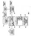
figure 1 . aprocessor 10 is connected to amemory controller hub 20. The processor may be a Pentium II ® dass processor other general purpose processor, or dedicated controller. The processor may be part of a worn station, desktop personal computer, portable computer, or telecommunications, video, or graphics device.Memory controller hub 20 is connected to and controlmain memory 30.Memory controller hub 20 also handles graphics traffic and traffic to and from the 1/O controller hub.Main memory 30 can be, for example, a RAMBUS memory system including multiple memory modules, each holding RDRAM memory chips. The individual modules can be of a comparable size to standard dual inline memory modules. - The
memory controller hub 20 interacts withmain memory 30 using a packetized protocol. The memory controller acts as an interpreter between the RAM bus andprocessor 10 so that the processor does to need to concern itself with the details of the RAM structure or operation. Other high speed RAM technologies using a memory controller to access main memory may be used as well. Memory controller hub 20 andmain memory 30 are clocked bymemory clock 40. For example, main memory may be differentially clocked at 400 MHZ using dual phase docking to provide an effective clock rate of 800 MHZ The processor is clocked byprocessor clock 50. Also coupled toprocessor 10 via I/O controller hub 55 isnonvolatile memory 60. Thenonvolatile memory 60 may be ROM, EPROM, EEPROM, battery-backed RAM, and the like. Thenonvolatile memory 60 stores the BIOS (basic input/output software) and may include SMM (system management mode software). The SMM may also reside in the main memory.- The
nonvolatile memory 60 stores theinitialization software 70 used to initializememory controller hub 20.Initialization software 70 may be part of the BIOS or part of the SMM software, if present. In some applications, the initialization software may be independent of the BIOS, for example, in systems that do not have BIOS software external toprocessor 10.Memory controller hub 20 includesinternal registers 90 that control the address space mapping ("PAM registers"). These registers control whether the address generator looks tononvolatile memory 60 for instructions and data or looks tomain memory 30. Alternately, the PAM registers may reside in I/O controller hub 55 or in a separate well in the processor such that power is not lost whenprocessor 10 is powered down. Connected toprocessor 10 is display orgraphics controller 95. Processor 10 may include cache 110 to speed up memory access time. The cache may be internal to the processor chip or package and may also be external. I/O controller 55 contains a waketrigger state machine 100 to process wake event triggers received from outside the processor.State machine 100 can also reside inmemory controller hub 20 orprocessor 10. This state machine enables the processor to respond to wake events at a time before any software begins to execute.- Once the system is running, the system is in an awake state,
memory controller hub 20 is initialized, portions ofoperating system 80 are loaded intomain memory 30, and the system is in normal operation. - Referring to
figure 2 , the operating system may determine that power should be conserved and that the system should enter a sleep state. This determination may be triggered based on an innumerable host of factors, such as a system idle time out, a request from a user, a request from a hardware device, such as a low battery or high temperature indication, or a request from an applications program. - Before entering a sleep state, in
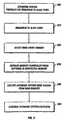
step 200 the operating system prepares for the transition. This preparation may include housekeeping tasks, cache flushing, context saving, and the like. The operating system may also determine which devices are to be placed in a "seep" state. In circumstances where a system is designed to maximize power savings, the entire system may be placed in a sleep state. In more simple designs, only the processor and the memory subsystem may be placed in a sleep state, while peripherals are left either fully powered or turned off. The operating system also selects the desired sleep state and sets the appropriate bit or bits in a sleep state register. For example, the ACPI specification includes the S1 and S2 sleep states that provide for a low latency return to the awake state. - In
step 210, the processor transitions to the sleep state. One way to accomplish this transition is to set the appropriate bits in a sleep enable register. Either a software or hardware process then detects that this bit is set and asserts a sleep signal to the appropriate components.Processor clock 50 is powered down. Powering down may be accomplished by disconnecting power from the device itself, or may be accomplished by electrically disconnecting the incoming signal from the internal distribution lines internal to each chip. For example,processor clock 50 may be left running, but the processor may electrically disconnect the incoming clock signal so the processor's internal components are not being clocked. Likewise, individual devices may be powered down with circuitry internal to the devices that prevent the flow of power to some or all of the components inside the device. In an RDRAM system,memory controller hub 20,main memory 30, andmemory clock 40 are powered down. When the main memory is power down, its contents are not lost, but the main memory devices transition to a power down state that consumes very little power. An internal self refresh mechanism withinmain memory 30 keeps the memory contents when main memory is powered down. Also,memory clock 40 transitions to a low power state. In the low power state, physical power may or may not be removed. - In
step 220, a wake event trigger is detected. This trigger signals thatprocessor 10 should resume normal operation. In some applications, this may be a return to full speed, full power mode. In other applications, the system may awaken to a more drowsy state whereprocessor 10 may not be running at full speed. The wake event trigger may be generated by a source outside the system itself, such as a user pressing a "power on" or "resume" key, an incoming call signal from a modem or other telephony receiver, or it may be generated by a timer tied to a particular time of day or some other event such as scheduled system maintenance. - In response to the detected wake event trigger, the system initializes the memory controller in
step 230. In an RDRAM system this includes initializing the RAC and the RDRAM core. Other functions performed during initialization may be recalibration of the RAM bus drivers, synchronization of the RAM bus clock, and a general reset of the memory controller. This initialization is not performed exclusively by the hardware, but rather involves executinginitialization software 70 fromnonvolatile memory 60. - After
memory controller hub 20 is initialized, control is passed instep 240 from theinitialization software 70 tooperating system 80 stored inmain memory 30.Operating system 80 now processes the wake event trigger. This processing can include restoring the processor context, performing a quick system diagnostic, or other routine typically executed following a wake event. Figure 3 shows an embodiment implementing the S1 sleep state with RDRAM. In normal operation, setting the sleep enable bit will cause the processor to transition to the S1 sleep state. In this embodiment, however, the system management mode software is used to mediate between the sleep state and the RDRAM. A portion of the system management mode software is stored innonvolatile memory 60 that also stores the BIOS (the BIOS storage device). The system management mode software, however, is inaccessible to the operating system. The operating system has no means by which it can directly jump to routines within the system management mode software.- To allow for control to efficiently and cleanly shift from the operating system to the system management mode software, the processor is configured to respond to a sleep trigger with a system management interrupt (SMI). To accomplish this, the operating system writes a bit to a register in
step 300. This register tells the hardware to generate an SMI in response to a sleep enable signal, rather than responding with a transition to a sleep state. In response to the SMI, the processor directs control to the system management mode software. Instep 310, the SMI Handler, which services the SMI, flushes the cache. This cache flush avoids unified write backs in the L2 cache on instruction fetches. If this step is performed, there will be no further memory writes until the processor transition from the sleep state. Next, as shown instep 320, the SMI Handler sets the PAM registers to point to the BIOS storage device. The PAM holds the address space mapping for the system. Once the PAM registers are pointing to the BIOS storage device, instructions and data will be fetched from that device and not from the RDRAM. Instep 330, the SMI Handler executes a jump/branch instruction that points to an entry in the BIOS storage device. - In
step 340, the SMI Handler clears the bit that causes the processor to generate an SMI in response to a sleep enable. The processor is now reconfigured to enter a sleep state in response to a sleep enable signal. Instep 350, the sleep enable bit is set for a second time. This time, however, it is the SMI Handler that sets the bit, not the operating system. The SMI Handler also identifies the desired sleep mode. In this embodiment the desired sleep mode is the S1 state. The processor detects that the sleep enable bit is set and, instep 360, the system transitions to the S1 sleep state. The processor clock and RDRAM clock are powered down. In this embodiment, the processor and RDRAM subsystem each have their own respective clocks. In other embodiments the processor and memory subsystem can use the same clock as their respective clocks. Once the RDRAM subsystem is powered down, it requires reinitialization. - In
step 370, a wake event trigger is received by the hardware signaling that the system should return to the awake state from the sleep state. The clocks are returned to their power on state. The processor resumes instruction fetching. Instep 380, the first instruction to be fetched is the instruction from the SMI Handler following the transition to the S1 state. Instep 385, the SMI Handler then executes the instructions to initialize the RDRAM. Instep 390, the SMI Handler then sets the PAM registers to point to an entry in the RDRAM. The SMI Handler then executes the return instruction and control transfers to the operating system. Instep 395, the operating system executes the next instruction following the instruction in which it set the sleep enable bit. The system has returned successfully from the sleep state and normal operation continues. Figure 4 shows an embodiment using the S2 state. The operating system desires to enter the sleep state instep 410 and stores the resume address used by the BIOS in the RDRAM. The operating system flushes the cache inStep 420, identifies the sleep state by writing the S2 state into the sleep type register, and enables the sleep state by writing the appropriate information into the sleep enable register. The processor and RDRAM clocks are powered down instep 430. In the S2 state, the power toprocessor 10 is actually removed so thatprocessor 10 is not consuming either active or leakage power.- The system is in the S2 state in
step 440. A wake event trigger is detected instep 450. Power is restored to the clocks. A processor reset (CPURST#) is also asserted resetting the processor. The system comes out of reset instep 460 and starts executing software at location FFFFFFF0h. The PAM registers are configured to point to the BIOS storage device and not to shadow this space in the RDRAM. Alternatively, a hardware state machine can respond to the wake event by changing the PAM registers to point to the BIOS storage device. Instep 470, the BIOS initializes the RDRAM. Instep 480, the BIOS redirects the PAM registers to execute software from the RDRAM. BIOS passes control to the operating system via the resume address stored in RDRAM instep 410. Instep 490, the operating system processes the wake event interrupt. Instep 495, recovery from the sleep state is complete and normal operation in the awake state resumes. Figure 5 shows a processor and memory subsystem within the context of a larger system, such as might be found in a desktop system, portable computer, portable communications device, set top box, or video and graphics controller.Processor 510 andmemory controller 520 are incorporated within the same chip. The processor interacts with thememory 530, preferably RDRAM, viamemory controller 520 throughmemory bus 535.Memory controller 520 wakes and is initialized by the execution of software fromBIOS storage device 540. It may be desirable in some applications to incorporate the BIOS storage device into the same chip asprocessor 510 andmemory controller 520.- Power to the system is supplied by
power source 545. In a portable system,power source 545 may be a battery. In desk top or set top devices, the power source may be a DC source drawing AC line power. The power is distributed bypower control circuitry 550. Power control circuitry is responsive to the processor to decrease or cut off power to various parts of the system.Power control circuitry 550 can also informprocessor 510 of a low power condition. As shown the power control circuitry interfaces with the processor in a manner independent ofmain bus 560. In other embodiments, the power control circuitry may be treated as any other peripheral connected to the main bus. In a desk top system, the main bus may be a PCI bus. Connected to the main bus aredisplay 580,high density storage 590, andperipherals 590. In some systems that are graphics intensive, display orgraphics controller 580 may have its own dedicated or high speed path to the processor. Display orgraphics controller 580 may be connected toprocessor 10 ormemory controller hub 20 through a separate bus or may be integrated with the memory controller in the processor core.High density storage 590 will typically be a hard drive.Peripherals 590 will vary with the particular application. - Referring to
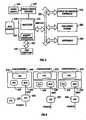
Figure 6 , three different configurations for a core chipset are shown. Configuration 1 has the processor 610 (CPU), graphics controller 620 (GFX), and memory controller 630 (also called a memory controller hub or MCH) integrated into a single chip 640. The I/O controller hub 650 (ICH) and video controller hub 655 (VCH) are shown as distinct chips. The VCH may also be incorporated into chip 640.ICH 650 controls the operation of the main bus, for example, themain bus 560 shown infigure 5 .ICH 650 has an output (NRST) that resets chip 640.ICH 650 has a separate output (PCIRST#) that resets the main bus, for example, a PCI bus. In configuration 2,processor 610,GFX 620, andMCH 630 are each in separate chips. In configuration 3,processor 610 is in its own chip.GFX 620 andMCH 630 are in a single chip. In configurations 2 and 3,CPU 610 has its own reset input under control ofICH 650. - In configuration 1 chip 640 and all its components are powered down in the sleep state, for example, an S2 state. In configuration 2,
CPU 610 andMCH 630 are powered down.GFX 620 is left powered to maintain a display. Alternatively,GFX 620 may be powered down to conserve even more power. In configuration 3,CPU 610,GFX 620, andMCH 630 are powered down. Powering down the components in addition to stopping the clocks substantially reduces leakage currents. Additionally, the interface betweenICH 650 and the other components is isolated. This interface is not a PCI interface, but a messaging protocol based interface. In each configuration, the ICH is left powered. The ICH has hardware necessary to recover from the sleep state. Reducing or eliminating leakage power in the S2 state fromCPU 610,GFX 620, andMCH 630 will extend battery life in a substantial way in 0.18 micron process technologies and beyond. - The disclosed embodiments are exemplary only. Other embodiments are within the scope of the following claims.
- The S1 and S2 sleep states of the ACPI Specification, Revision 1. 0b, released February 2, 1999:
- The S1 state is defined as a low wakeup latency sleeping state. In this state no system context is lost (CPU or chip set), and the hardware is responsible for maintaining all system context, which includes the context of the CPU, caches, memory, and all chipset I/O. Examples of S1 sleeping state implementation alternatives follow.
- This example references an IA processor that supports the stop grant state through the assertion of the STPCLK# signal. When SLP_TYPx is programmed to the S1 value (the OEM chooses a value, which is then placed in the \_Si1 object) and the SLP_ENx bit is subsequently set, the hardware can implement an S1 state by asserting the STPCLK# signal to the processor, causing it to enter the stop grant state. In this case, the system clocks (PCI and CPU) are still running. Any enabled wakeup event should cause the hardware to de-assert the STPCLK# signal to the processor. 9.1.1.2 S1 Sleeping State Implementation (Example 2) When SLP_TYPx is programmed to the S1 value and the SLP_ENx bit is subsequently set, the hardware will implement an S1 state by doing the following:
- 1. Place the processor into the stop grant state.
- 2. Stop the processor's input clock, placing the processor into the stop clock state.
- 3. Places system memory into a self-refresh or suspend-refresh state. Refresh is maintained by the memory itself or through some other reference clock that is not stopped during the sleeping state.
- 4. Stop all system clocks (asserts the standby signal to the system PLL chip). Normally the RTC will continue running.
- In this case, all clocks in the system have been stopped (except for the RTC's clock). Hardware must reverse the process (restarting system clocks) upon any enabled wakeup event.
- The S2 state is defined as a low wakeup latency sleep state. This state is similar to the S1 sleeping state, except that the CPU and system cache context is lost (the OS is responsible for maintaining the caches and CPU context). Additionally, control starts from the processor's reset vector after the wakeup event. Before setting the SLP_EN bit, the ACPI driver will flush the system caches. If the platform supports the WBINVD instruction (as indicated by the WBINVD and WBINVD_FLUSH flags in the FACP table), the OS will execute the WBINVD instruction. If the platform does not support the WBINVD instruction to flush the caches, then the ACPI driver will attempt to manually flush the caches using the FLUSH_SIZE and FLUSH_STRIDE fields in the FACP table. The hardware is responsible for maintaining chipset and memory context. An example of a S2 sleeping state implementation follows.
- When SLP-TYPx is programmed to the S2 value (found in the S2 object) and then the SLP_EN bit is set, the hardware will implement an S2 state by doing the following:
- Stop system clocks (the only running clock is the RTC).
- Place system memory into a self or suspend refresh state.
- Power off the CPU and cache subsystem.
- In this case, the CPU is reset upon detection of the wakeup event; however, core logic and memory maintain their context. Execution control starts from the CPU's boot vector. The BIOS is required to:
- Program the initial boot configuration of the CPU (such as the CPU's MSR and MTRR registers).
- Initialize the cache controller to its initial boot size and configuration.
- Enable the memory controller to accept memory accesses.
- Call the waking vector.
Claims (31)
- A method for transitioning between a sleep state and an awake state of a system in a system comprising a processor (10), a main memory (30), a memory controller (20), and a non-volatile memory (60), the method, for transitioning from the sleep state to the awake state of the system, comprising:detecting a wake event trigger to transition the system from said sleep state to said awake state;initialising the memory controller in response to the detecting, the initialising comprising executing initialization software (70) stored in the non-volatile memory;and executing operating system software (80) which processes the wake event trigger stored in the main memory (30) after the initialising.
- The method of claim 1, further comprising:preparing, under control of operating system software (80) which processes the wake event trigger stored in the main memory, for a transition from the awake state to the sleep state; andtransitioning to the sleep state.
- The method of claim 1, wherein the main memory comprises RDRAM.
- The method of claim 1, wherein the memory controller resides in the same chip as the processor.
- The method of claim 1, wherein the initialization software (70) in the non-volatile memory comprises BIOS software.
- The method of claim 1, wherein the initialization software (70) in the non-volatile memory comprises software inaccessible by operating system software in the main memory.
- The method of claim 1, wherein the initialization software (70) in the non-volatile memory comprises system management mode software.
- The method of claim 1, wherein the processor and memory controller have inputs for receiving respective clock signals, the method further comprising preventing the receiving of the respective clock signals prior to the detecting.
- The method of claim 2, wherein the preparing comprises:configuring the processor to execute the initialization software (70) stored in the non-volatile memory in response to a sleep trigger signal from the operating system;receiving a first sleep trigger signal from the operating system;executing the initialisation software (70) stored in the non-volatile memory in response to the receiving;reconfiguring the processor to transition to the sleep state in response to a sleep trigger signal; andreceiving a second sleep trigger signal.
- The method of claim 9, wherein the initialization software (70) stored in the non-volatile memory comprises system management mode software, the method further comprising generating a system management interrupt in response to the receiving of the first sleep trigger.
- The method of claim 9 wherein the initialising executes the initialization software (70) stored in the non-volatile memory at the instruction following the last instruction executed before transitioning to the sleep state.
- The method of claim 2, wherein the transitioning transitions the processor into an S1 state.
- The method of claim 2, wherein the transitioning transitions the processor into an S2 state.
- The method of claim 2, wherein the preparing comprises flushing a cache.
- The method of claim 2, further comprising resetting the processor prior to the initialising.
- The method of claim 2. wherein the preparing comprises configuring address space mapping to point to the non-volatile memory following the detecting.
- The method of claim 1, further comprising:storing a resume address in the main memory; andtransferring control from the initialization software (70) in the non-volatile memory to the software in the main memory following the initialising using the resume address stored in the main memory.
- The method of claim 1, further comprising powering down the main memory controller prior to the detecting.
- A system having an awake state and a sleep state, comprising:a processor (10);a main memory (30);a memory controller (20);a non-volatile memory (60);said non-volatile memory comprising initialization software (70) that executes to initialise the memory controller responsive to a wake event trigger to transition the system from the sleep state to the awake state; andsaid main memory comprising operating system software (80) that executes after the memory controller has been initialised, wherein the operating system software processes the wake event trigger.
- The system of claim 19, wherein:the non-volatile memory stores BIOS software as the initialization software (70); andthe operating system software (80) is configured to control a transition from the awake state to the sleep state.
- The system of claim 20, wherein:the operating system stores a BIOS resume address in the main memory prior to a transition from the awake state to the sleep state; andthe BIOS software returns controls to the operating system using the stored BIOS resume address after the memory controller is initialised.
- The system of claim 20, wherein the main memory comprises RDRAM.
- The system of claim 20, wherein the non-volatile memory comprises RAM.
- The system of claim 20, further comprising system management mode software, the system management mode software being inaccessible by the operating system, and wherein the system management mode software initialises the main memory.
- The system of claim 19, wherein the processor, main memory, and memory controller have clock inputs, the system comprising clock disable circuitry preventing the internal docking of the processor, main memory, and memory controller.
- The system of claim 19, wherein the processor and memory controller reside within a common chip.
- The system of claim 19, further comprising cache residing in the same chip as the processor and the memory controller and wherein the operating system is configured to flush the cache prior to the transition from the awake state to the sleep state.
- The system of claim 19, wherein the processor and memory controller are not clocked in the sleep state.
- The system of claim 19, further comprising circuitry to disable the flow of power internal to the processor, memory controller, and main memory.
- The method of claim 17, wherein the software in the main memory comprises operating system software (80), and the initialization software (70) in the non-volatile memory comprises BIOS software.
- The system of claim 19, further comprising:a power storage medium;a display;a processor clock;wherein the system is a portable computer system.
Applications Claiming Priority (3)
| Application Number | Priority Date | Filing Date | Title |
|---|---|---|---|
| US434973 | 1982-10-18 | ||
| US09/434,973US6571333B1 (en) | 1999-11-05 | 1999-11-05 | Initializing a memory controller by executing software in second memory to wakeup a system |
| PCT/US2000/041489WO2001033322A2 (en) | 1999-11-05 | 2000-10-23 | Sleep state transitioning |
Publications (2)
| Publication Number | Publication Date |
|---|---|
| EP1228413A2 EP1228413A2 (en) | 2002-08-07 |
| EP1228413B1true EP1228413B1 (en) | 2011-05-18 |
Family
ID=23726471
Family Applications (1)
| Application Number | Title | Priority Date | Filing Date |
|---|---|---|---|
| EP00992954AExpired - LifetimeEP1228413B1 (en) | 1999-11-05 | 2000-10-23 | Sleep state transitioning |
Country Status (10)
| Country | Link |
|---|---|
| US (3) | US6571333B1 (en) |
| EP (1) | EP1228413B1 (en) |
| JP (1) | JP3701910B2 (en) |
| CN (1) | CN100530043C (en) |
| AT (1) | ATE510250T1 (en) |
| AU (1) | AU4609401A (en) |
| HK (1) | HK1052569B (en) |
| SG (1) | SG122817A1 (en) |
| TW (1) | TW498194B (en) |
| WO (1) | WO2001033322A2 (en) |
Cited By (1)
| Publication number | Priority date | Publication date | Assignee | Title |
|---|---|---|---|---|
| WO2014098995A1 (en)* | 2012-12-19 | 2014-06-26 | Intel Corporation | Adaptively disabling and enabling sleep states for power and performance |
Families Citing this family (99)
| Publication number | Priority date | Publication date | Assignee | Title |
|---|---|---|---|---|
| US7325125B2 (en)* | 1999-06-14 | 2008-01-29 | Via Technologies, Inc. | Computer system for accessing initialization data and method therefor |
| TW436685B (en)* | 1999-06-14 | 2001-05-28 | Via Tech Inc | Computer system for accessing initialization dada and its method |
| US6571333B1 (en)* | 1999-11-05 | 2003-05-27 | Intel Corporation | Initializing a memory controller by executing software in second memory to wakeup a system |
| US6886105B2 (en)* | 2000-02-14 | 2005-04-26 | Intel Corporation | Method and apparatus for resuming memory operations from a low latency wake-up low power state |
| US6633987B2 (en) | 2000-03-24 | 2003-10-14 | Intel Corporation | Method and apparatus to implement the ACPI(advanced configuration and power interface) C3 state in a RDRAM based system |
| US7017056B1 (en)* | 2000-07-31 | 2006-03-21 | Hewlett-Packard Development Company, L.P. | Method and apparatus for secure remote control of power-on state for computers |
| US6968219B2 (en)* | 2001-08-15 | 2005-11-22 | Qualcomm, Incorporated | Method for reducing power consumption in bluetooth and CDMA modes of operation |
| US7020643B2 (en) | 2002-01-25 | 2006-03-28 | Microsoft Corporation | Method and system for clickpath funnel analysis |
| US6965763B2 (en)* | 2002-02-11 | 2005-11-15 | Motorola, Inc. | Event coordination in an electronic device to reduce current drain |
| US7093115B2 (en)* | 2002-12-19 | 2006-08-15 | Intel Corporation | Method and apparatus for detecting an interruption in memory initialization |
| JP3756882B2 (en) | 2003-02-20 | 2006-03-15 | 株式会社東芝 | Information processing apparatus and information processing method |
| US8934597B2 (en)* | 2003-03-12 | 2015-01-13 | Infineon Technologies Ag | Multiple delay locked loop integration system and method |
| US8749561B1 (en) | 2003-03-14 | 2014-06-10 | Nvidia Corporation | Method and system for coordinated data execution using a primary graphics processor and a secondary graphics processor |
| TW591372B (en)* | 2003-05-15 | 2004-06-11 | High Tech Comp Corp | Power control method of portable electronic device, portable electronic device and electronic system |
| DE10323861A1 (en)* | 2003-05-26 | 2004-12-30 | Infineon Technologies Ag | Integrated circuit and method for operating the integrated circuit, in particular for putting the same into a power-saving mode |
| US7363411B2 (en)* | 2003-10-06 | 2008-04-22 | Intel Corporation | Efficient system management synchronization and memory allocation |
| US7493435B2 (en)* | 2003-10-06 | 2009-02-17 | Intel Corporation | Optimization of SMI handling and initialization |
| CN1609825A (en)* | 2003-10-23 | 2005-04-27 | 南京易思克网络安全技术有限责任公司 | Apparatus and method for realizing computing equipment status safety transition |
| US20050108585A1 (en)* | 2003-11-19 | 2005-05-19 | Yang Chiang H. | Silent loading of executable code |
| US8385985B2 (en)* | 2003-11-25 | 2013-02-26 | Qualcomm Incorporated | Method for reducing power consumption in a multi-mode device |
| US7340561B2 (en)* | 2004-01-08 | 2008-03-04 | Hewlett-Packard Development Company, L.P. | Computer memory initialization |
| CN1332288C (en)* | 2004-01-09 | 2007-08-15 | 佛山市顺德区顺达电脑厂有限公司 | Computer device CPU time-pulse speed real-time adjusting method |
| US7181188B2 (en)* | 2004-03-23 | 2007-02-20 | Freescale Semiconductor, Inc. | Method and apparatus for entering a low power mode |
| US20050278513A1 (en)* | 2004-05-19 | 2005-12-15 | Aris Aristodemou | Systems and methods of dynamic branch prediction in a microprocessor |
| DE102004032237A1 (en)* | 2004-07-02 | 2006-01-26 | Infineon Technologies Ag | Configuration of devices transitioning from a low power operating mode to a normal power operating mode |
| US20060067348A1 (en)* | 2004-09-30 | 2006-03-30 | Sanjeev Jain | System and method for efficient memory access of queue control data structures |
| US7277990B2 (en) | 2004-09-30 | 2007-10-02 | Sanjeev Jain | Method and apparatus providing efficient queue descriptor memory access |
| US7412596B2 (en)* | 2004-10-16 | 2008-08-12 | Lenovo (Singapore) Pte. Ltd. | Method for preventing system wake up from a sleep state if a boot log returned during the system wake up cannot be authenticated |
| EP1653331B8 (en) | 2004-10-29 | 2012-03-14 | ST-Ericsson SA | An apparatus and method for entering and exiting low power mode |
| US7555630B2 (en)* | 2004-12-21 | 2009-06-30 | Intel Corporation | Method and apparatus to provide efficient communication between multi-threaded processing elements in a processor unit |
| US7418543B2 (en) | 2004-12-21 | 2008-08-26 | Intel Corporation | Processor having content addressable memory with command ordering |
| US20060140203A1 (en)* | 2004-12-28 | 2006-06-29 | Sanjeev Jain | System and method for packet queuing |
| US7467256B2 (en)* | 2004-12-28 | 2008-12-16 | Intel Corporation | Processor having content addressable memory for block-based queue structures |
| US9384818B2 (en) | 2005-04-21 | 2016-07-05 | Violin Memory | Memory power management |
| US7218566B1 (en)* | 2005-04-28 | 2007-05-15 | Network Applicance, Inc. | Power management of memory via wake/sleep cycles |
| US8743019B1 (en) | 2005-05-17 | 2014-06-03 | Nvidia Corporation | System and method for abstracting computer displays across a host-client network |
| US7953980B2 (en) | 2005-06-30 | 2011-05-31 | Intel Corporation | Signed manifest for run-time verification of software program identity and integrity |
| US8839450B2 (en) | 2007-08-02 | 2014-09-16 | Intel Corporation | Secure vault service for software components within an execution environment |
| US7519790B2 (en)* | 2005-11-14 | 2009-04-14 | Intel Corporation | Method, apparatus and system for memory instructions in processors with embedded memory controllers |
| US7895309B2 (en)* | 2006-01-11 | 2011-02-22 | Microsoft Corporation | Network event notification and delivery |
| JP2007249660A (en)* | 2006-03-16 | 2007-09-27 | Toshiba Corp | Information processing apparatus and system state control method |
| US9195428B2 (en)* | 2006-04-05 | 2015-11-24 | Nvidia Corporation | Method and system for displaying data from auxiliary display subsystem of a notebook on a main display of the notebook |
| US8775704B2 (en) | 2006-04-05 | 2014-07-08 | Nvidia Corporation | Method and system for communication between a secondary processor and an auxiliary display subsystem of a notebook |
| US7797555B2 (en)* | 2006-05-12 | 2010-09-14 | Intel Corporation | Method and apparatus for managing power from a sequestered partition of a processing system |
| US20070290333A1 (en)* | 2006-06-16 | 2007-12-20 | Intel Corporation | Chip stack with a higher power chip on the outside of the stack |
| US9015501B2 (en)* | 2006-07-13 | 2015-04-21 | International Business Machines Corporation | Structure for asymmetrical performance multi-processors |
| US8806228B2 (en)* | 2006-07-13 | 2014-08-12 | International Business Machines Corporation | Systems and methods for asymmetrical performance multi-processors |
| US7716504B2 (en)* | 2006-07-13 | 2010-05-11 | Dell Products L.P. | System for retaining power management settings across sleep states |
| CN101114189B (en)* | 2006-07-28 | 2010-05-26 | 佛山市顺德区顺达电脑厂有限公司 | Asynchronous sequence transmitting system wake-up method |
| US20080072084A1 (en)* | 2006-09-20 | 2008-03-20 | Chao-Kuang Yang | Method for Power Management |
| US7752474B2 (en)* | 2006-09-22 | 2010-07-06 | Apple Inc. | L1 cache flush when processor is entering low power mode |
| US7822960B2 (en)* | 2006-12-22 | 2010-10-26 | Intel Corporation | Platform management processor assisted resume |
| TWI394369B (en)* | 2006-12-22 | 2013-04-21 | Hon Hai Prec Ind Co Ltd | Circuit for improving sequence |
| US7971084B2 (en) | 2007-12-28 | 2011-06-28 | Intel Corporation | Power management in electronic systems |
| US9766672B2 (en) | 2007-12-28 | 2017-09-19 | Intel Corporation | System for managing power provided to a processor or memory based on a measured memory consumption characteristic |
| US20090292934A1 (en)* | 2008-05-22 | 2009-11-26 | Ati Technologies Ulc | Integrated circuit with secondary-memory controller for providing a sleep state for reduced power consumption and method therefor |
| US8736617B2 (en) | 2008-08-04 | 2014-05-27 | Nvidia Corporation | Hybrid graphic display |
| US8799425B2 (en)* | 2008-11-24 | 2014-08-05 | Nvidia Corporation | Configuring display properties of display units on remote systems |
| US20100138768A1 (en)* | 2008-12-02 | 2010-06-03 | Nvidia Corporation | Simplifying Configuration Of Multiple Display Units For Common Use |
| WO2010077923A2 (en)* | 2008-12-16 | 2010-07-08 | The Regents Of The University Of Michigan | Computer energy conservation with a scalable psu configuration |
| US8498229B2 (en)* | 2008-12-30 | 2013-07-30 | Intel Corporation | Reduced power state network processing |
| US8364601B2 (en)* | 2008-12-31 | 2013-01-29 | Intel Corporation | Methods and systems to directly render an image and correlate corresponding user input in a secure memory domain |
| US9001071B2 (en)* | 2009-02-23 | 2015-04-07 | Novatek Microelectronics Corp. | Energy-efficient touch panel device and related method |
| US9075559B2 (en)* | 2009-02-27 | 2015-07-07 | Nvidia Corporation | Multiple graphics processing unit system and method |
| US9135675B2 (en) | 2009-06-15 | 2015-09-15 | Nvidia Corporation | Multiple graphics processing unit display synchronization system and method |
| US8601302B2 (en)* | 2009-06-22 | 2013-12-03 | Amazon Technologies, Inc. | Processor system in low power state retention mode with linear regulator off and switch regulator low in power management IC |
| US8766989B2 (en)* | 2009-07-29 | 2014-07-01 | Nvidia Corporation | Method and system for dynamically adding and removing display modes coordinated across multiple graphics processing units |
| KR101596222B1 (en)* | 2009-08-25 | 2016-02-23 | 삼성전자주식회사 | Method and apparatus for controlling operation of booting for video image reproducing apparatus |
| EP2299681B1 (en)* | 2009-09-08 | 2019-05-15 | HP Printing Korea Co., Ltd. | Image forming apparatus and power control method thereof |
| US8339626B2 (en) | 2009-09-08 | 2012-12-25 | Samsung Electronics Co., Ltd. | Image forming apparatus and controlling method thereof |
| US8780122B2 (en) | 2009-09-16 | 2014-07-15 | Nvidia Corporation | Techniques for transferring graphics data from system memory to a discrete GPU |
| US9111325B2 (en) | 2009-12-31 | 2015-08-18 | Nvidia Corporation | Shared buffer techniques for heterogeneous hybrid graphics |
| US8514611B2 (en) | 2010-08-04 | 2013-08-20 | Freescale Semiconductor, Inc. | Memory with low voltage mode operation |
| US8806232B2 (en)* | 2010-09-30 | 2014-08-12 | Apple Inc. | Systems and method for hardware dynamic cache power management via bridge and power manager |
| US8068373B1 (en) | 2010-10-25 | 2011-11-29 | Network Appliance, Inc. | Power management of memory via wake/sleep cycles |
| CN102592066A (en)* | 2011-01-14 | 2012-07-18 | 金鹏科技有限公司 | Fingerprint password device adaptive to intelligent device and processing method thereof |
| TWI528162B (en) | 2011-01-26 | 2016-04-01 | 威盛電子股份有限公司 | Computer system and operating system switching method thereof |
| US9021284B2 (en)* | 2011-09-08 | 2015-04-28 | Infineon Technologies Ag | Standby operation with additional micro-controller |
| US8719609B2 (en)* | 2011-10-12 | 2014-05-06 | Apple Inc. | Using latched events to manage sleep/wake sequences on computer systems |
| CN103975287B (en) | 2011-12-13 | 2017-04-12 | 英特尔公司 | Enhanced system sleep state support in servers using non-volatile random access memory |
| US8230247B2 (en) | 2011-12-30 | 2012-07-24 | Intel Corporation | Transferring architectural functions of a processor to a platform control hub responsive to the processor entering a deep sleep state |
| JP6007642B2 (en) | 2012-01-26 | 2016-10-12 | 株式会社リコー | Information processing apparatus, power saving control method, power saving control program |
| US9182999B2 (en)* | 2012-05-30 | 2015-11-10 | Advanced Micro Devices, Inc. | Reintialization of a processing system from volatile memory upon resuming from a low-power state |
| KR20150098649A (en) | 2012-12-22 | 2015-08-28 | 퀄컴 인코포레이티드 | Reducing power consumption of volatile memory via use of non-volatile memory |
| JP6322891B2 (en)* | 2013-02-20 | 2018-05-16 | 日本電気株式会社 | Computer apparatus suitable for intermittent operation and operation method thereof |
| US9818379B2 (en) | 2013-08-08 | 2017-11-14 | Nvidia Corporation | Pixel data transmission over multiple pixel interfaces |
| CN105960633B (en)* | 2014-02-07 | 2020-06-19 | 株式会社半导体能源研究所 | Semiconductor device, device and electronic apparatus |
| WO2015152893A1 (en)* | 2014-03-31 | 2015-10-08 | Cfph, Llc | Resource allocation |
| US9785447B2 (en)* | 2014-06-27 | 2017-10-10 | Intel Corporation | System standby emulation with fast resume |
| US10198274B2 (en)* | 2015-03-27 | 2019-02-05 | Intel Corporation | Technologies for improved hybrid sleep power management |
| US10078356B2 (en)* | 2015-08-20 | 2018-09-18 | Intel Corporation | Apparatus and method for saving and restoring data for power saving in a processor |
| CN105433904A (en) | 2015-11-24 | 2016-03-30 | 小米科技有限责任公司 | Sleep state detection method, device and system |
| US9898351B2 (en)* | 2015-12-24 | 2018-02-20 | Intel Corporation | Method and apparatus for user-level thread synchronization with a monitor and MWAIT architecture |
| US10360114B2 (en)* | 2016-02-24 | 2019-07-23 | Quanta Computer Inc. | Hardware recovery systems |
| JP6859654B2 (en) | 2016-10-11 | 2021-04-14 | 株式会社リコー | Equipment, information processing systems, information processing methods and information processing programs |
| CN111124518B (en)* | 2019-12-24 | 2024-01-30 | 西安闻泰电子科技有限公司 | System sleep control circuit and control method thereof |
| CN115129227A (en)* | 2021-03-24 | 2022-09-30 | 致真存储(北京)科技有限公司 | A data storage method using Cortex-M chip system and Cortex-M chip system |
| US20230418590A1 (en)* | 2022-06-22 | 2023-12-28 | Hewlett-Packard Development Company, L.P. | Instruction updates |
| CN117950737B (en)* | 2024-03-22 | 2024-07-26 | 荣耀终端有限公司 | Wake-up processing method, device, electronic device and computer-readable storage medium |
Family Cites Families (19)
| Publication number | Priority date | Publication date | Assignee | Title |
|---|---|---|---|---|
| US4924169A (en)* | 1987-12-17 | 1990-05-08 | Dana Corporation | Current regulator for a battery re-charging circuit |
| US5499384A (en)* | 1992-12-31 | 1996-03-12 | Seiko Epson Corporation | Input output control unit having dedicated paths for controlling the input and output of data between host processor and external device |
| US5608884A (en)* | 1995-05-17 | 1997-03-04 | Dell Usa, L.P. | Commonly housed multiple processor type computing system and method of manufacturing the same |
| US5764999A (en)* | 1995-10-10 | 1998-06-09 | Cyrix Corporation | Enhanced system management mode with nesting |
| US5692202A (en)* | 1995-12-29 | 1997-11-25 | Intel Corporation | System, apparatus, and method for managing power in a computer system |
| US5657445A (en)* | 1996-01-26 | 1997-08-12 | Dell Usa, L.P. | Apparatus and method for limiting access to mass storage devices in a computer system |
| JP3798476B2 (en) | 1996-08-30 | 2006-07-19 | 株式会社東芝 | Computer system and cache memory power-down control method in the system |
| US5983353A (en)* | 1997-01-21 | 1999-11-09 | Dell Usa, L.P. | System and method for activating a deactivated device by standardized messaging in a network |
| EP0855718A1 (en)* | 1997-01-28 | 1998-07-29 | Hewlett-Packard Company | Memory low power mode control |
| US5919264A (en)* | 1997-03-03 | 1999-07-06 | Microsoft Corporation | System and method for using data structures to share a plurality of power resources among a plurality of devices |
| US6125449A (en)* | 1997-06-30 | 2000-09-26 | Compaq Computer Corporation | Controlling power states of a computer |
| US5958058A (en)* | 1997-07-18 | 1999-09-28 | Micron Electronics, Inc. | User-selectable power management interface with application threshold warnings |
| US6263448B1 (en) | 1997-10-10 | 2001-07-17 | Rambus Inc. | Power control system for synchronous memory device |
| US6078290A (en)* | 1998-01-06 | 2000-06-20 | Trimble Navigation Limited | User-controlled GPS receiver |
| US6122748A (en)* | 1998-03-31 | 2000-09-19 | Compaq Computer Corporation | Control of computer system wake/sleep transitions |
| US6378056B2 (en)* | 1998-11-03 | 2002-04-23 | Intel Corporation | Method and apparatus for configuring a memory device and a memory channel using configuration space registers |
| US6308285B1 (en)* | 1999-02-17 | 2001-10-23 | Compaq Computer Corporation | Warm processor swap in a multiprocessor personal computer system |
| US6393573B1 (en)* | 1999-07-14 | 2002-05-21 | Visteon Global Technologies, Inc. | Power management for automotive multimedia system |
| US6571333B1 (en)* | 1999-11-05 | 2003-05-27 | Intel Corporation | Initializing a memory controller by executing software in second memory to wakeup a system |
- 1999
- 1999-11-05USUS09/434,973patent/US6571333B1/ennot_activeExpired - Lifetime
- 2000
- 2000-10-23CNCNB008180555Apatent/CN100530043C/ennot_activeExpired - Fee Related
- 2000-10-23WOPCT/US2000/041489patent/WO2001033322A2/enactiveApplication Filing
- 2000-10-23EPEP00992954Apatent/EP1228413B1/ennot_activeExpired - Lifetime
- 2000-10-23ATAT00992954Tpatent/ATE510250T1/ennot_activeIP Right Cessation
- 2000-10-23JPJP2001535146Apatent/JP3701910B2/ennot_activeExpired - Fee Related
- 2000-10-23HKHK03104851.7Apatent/HK1052569B/ennot_activeIP Right Cessation
- 2000-10-23AUAU46094/01Apatent/AU4609401A/ennot_activeAbandoned
- 2000-10-23SGSG200401528Apatent/SG122817A1/enunknown
- 2000-10-31TWTW089122899Apatent/TW498194B/ennot_activeIP Right Cessation
- 2003
- 2003-03-12USUS10/386,749patent/US6782472B2/ennot_activeExpired - Lifetime
- 2004
- 2004-06-08USUS10/862,946patent/US20040225907A1/ennot_activeAbandoned
Cited By (2)
| Publication number | Priority date | Publication date | Assignee | Title |
|---|---|---|---|---|
| WO2014098995A1 (en)* | 2012-12-19 | 2014-06-26 | Intel Corporation | Adaptively disabling and enabling sleep states for power and performance |
| US9535483B2 (en) | 2012-12-19 | 2017-01-03 | Intel Corporation | Adaptively disabling and enabling sleep states for power and performance |
Also Published As
| Publication number | Publication date |
|---|---|
| JP2003519830A (en) | 2003-06-24 |
| US20030172313A1 (en) | 2003-09-11 |
| AU4609401A (en) | 2001-05-14 |
| TW498194B (en) | 2002-08-11 |
| SG122817A1 (en) | 2006-06-29 |
| EP1228413A2 (en) | 2002-08-07 |
| CN1415085A (en) | 2003-04-30 |
| WO2001033322A3 (en) | 2002-06-06 |
| JP3701910B2 (en) | 2005-10-05 |
| US6782472B2 (en) | 2004-08-24 |
| US6571333B1 (en) | 2003-05-27 |
| ATE510250T1 (en) | 2011-06-15 |
| US20040225907A1 (en) | 2004-11-11 |
| WO2001033322A2 (en) | 2001-05-10 |
| HK1052569A1 (en) | 2003-09-19 |
| CN100530043C (en) | 2009-08-19 |
| HK1052569B (en) | 2010-04-23 |
Similar Documents
| Publication | Publication Date | Title |
|---|---|---|
| EP1228413B1 (en) | Sleep state transitioning | |
| US6760850B1 (en) | Method and apparatus executing power on self test code to enable a wakeup device for a computer system responsive to detecting an AC power source | |
| US6243831B1 (en) | Computer system with power loss protection mechanism | |
| US6446213B1 (en) | Software-based sleep control of operating system directed power management system with minimum advanced configuration power interface (ACPI)-implementing hardware | |
| US6718475B2 (en) | Multi-processor mobile computer system having one processor integrated with a chipset | |
| US6711691B1 (en) | Power management for computer systems | |
| US6360327B1 (en) | System with control registers for managing computer legacy peripheral devices using an advanced configuration power interface software power management system | |
| US6654896B1 (en) | Handling of multiple compliant and non-compliant wake-up sources in a computer system | |
| US5369771A (en) | Computer with transparent power-saving manipulation of CPU clock | |
| US5630143A (en) | Microprocessor with externally controllable power management | |
| KR100397025B1 (en) | Clock control unit responsive to a power management state for clocking multiple clocked circuits connected thereto | |
| EP2188693B1 (en) | Apparatus and method for reducing power consumption in system on chip | |
| JPH06502510A (en) | Slow memory refresh on computers with limited power supplies | |
| EP2843502B1 (en) | Information processing device, information processing method, and program | |
| US5632037A (en) | Microprocessor having power management circuitry with coprocessor support | |
| US6886105B2 (en) | Method and apparatus for resuming memory operations from a low latency wake-up low power state | |
| CN102037428A (en) | Integrated circuit and method with secondary memory controller for providing sleep states with reduced power consumption | |
| WO2001035200A1 (en) | Dynamically adjusting a processor's operational parameters according to its environment | |
| JPH0850523A (en) | Method and equipment for management of power consumption in computer system | |
| US20040255176A1 (en) | Method and apparatus for improved reliability and reduced power in a processor by automatic voltage control during processor idle states | |
| EP0562885B1 (en) | Reduction of power consumption in microprocessor devices | |
| EP1229430B1 (en) | Power management system and method | |
| US7272731B2 (en) | Information handling system having reduced power consumption | |
| JP3860467B2 (en) | Power saving method and system for computer | |
| CN114415820A (en) | Power management method and system for processor platform |
Legal Events
| Date | Code | Title | Description |
|---|---|---|---|
| PUAI | Public reference made under article 153(3) epc to a published international application that has entered the european phase | Free format text:ORIGINAL CODE: 0009012 | |
| 17P | Request for examination filed | Effective date:20020531 | |
| AK | Designated contracting states | Kind code of ref document:A2 Designated state(s):AT BE CH CY DE DK ES FI FR GB GR IE IT LI LU MC NL PT SE | |
| AX | Request for extension of the european patent | Free format text:AL;LT;LV;MK;RO;SI | |
| 17Q | First examination report despatched | Effective date:20041116 | |
| GRAP | Despatch of communication of intention to grant a patent | Free format text:ORIGINAL CODE: EPIDOSNIGR1 | |
| GRAS | Grant fee paid | Free format text:ORIGINAL CODE: EPIDOSNIGR3 | |
| GRAJ | Information related to disapproval of communication of intention to grant by the applicant or resumption of examination proceedings by the epo deleted | Free format text:ORIGINAL CODE: EPIDOSDIGR1 | |
| 17Q | First examination report despatched | Effective date:20041116 | |
| REG | Reference to a national code | Ref country code:HK Ref legal event code:WD Ref document number:1048378 Country of ref document:HK | |
| GRAP | Despatch of communication of intention to grant a patent | Free format text:ORIGINAL CODE: EPIDOSNIGR1 | |
| GRAS | Grant fee paid | Free format text:ORIGINAL CODE: EPIDOSNIGR3 | |
| GRAA | (expected) grant | Free format text:ORIGINAL CODE: 0009210 | |
| AK | Designated contracting states | Kind code of ref document:B1 Designated state(s):AT BE CH CY DE DK ES FI FR GB GR IE IT LI LU MC NL PT SE | |
| REG | Reference to a national code | Ref country code:GB Ref legal event code:FG4D | |
| REG | Reference to a national code | Ref country code:CH Ref legal event code:EP | |
| REG | Reference to a national code | Ref country code:IE Ref legal event code:FG4D | |
| REG | Reference to a national code | Ref country code:DE Ref legal event code:R096 Ref document number:60045984 Country of ref document:DE Effective date:20110630 | |
| REG | Reference to a national code | Ref country code:NL Ref legal event code:VDEP Effective date:20110518 | |
| PG25 | Lapsed in a contracting state [announced via postgrant information from national office to epo] | Ref country code:SE Free format text:LAPSE BECAUSE OF FAILURE TO SUBMIT A TRANSLATION OF THE DESCRIPTION OR TO PAY THE FEE WITHIN THE PRESCRIBED TIME-LIMIT Effective date:20110518 Ref country code:PT Free format text:LAPSE BECAUSE OF FAILURE TO SUBMIT A TRANSLATION OF THE DESCRIPTION OR TO PAY THE FEE WITHIN THE PRESCRIBED TIME-LIMIT Effective date:20110919 | |
| PG25 | Lapsed in a contracting state [announced via postgrant information from national office to epo] | Ref country code:GR Free format text:LAPSE BECAUSE OF FAILURE TO SUBMIT A TRANSLATION OF THE DESCRIPTION OR TO PAY THE FEE WITHIN THE PRESCRIBED TIME-LIMIT Effective date:20110819 Ref country code:CY Free format text:LAPSE BECAUSE OF FAILURE TO SUBMIT A TRANSLATION OF THE DESCRIPTION OR TO PAY THE FEE WITHIN THE PRESCRIBED TIME-LIMIT Effective date:20110518 Ref country code:BE Free format text:LAPSE BECAUSE OF FAILURE TO SUBMIT A TRANSLATION OF THE DESCRIPTION OR TO PAY THE FEE WITHIN THE PRESCRIBED TIME-LIMIT Effective date:20110518 Ref country code:AT Free format text:LAPSE BECAUSE OF FAILURE TO SUBMIT A TRANSLATION OF THE DESCRIPTION OR TO PAY THE FEE WITHIN THE PRESCRIBED TIME-LIMIT Effective date:20110518 Ref country code:ES Free format text:LAPSE BECAUSE OF FAILURE TO SUBMIT A TRANSLATION OF THE DESCRIPTION OR TO PAY THE FEE WITHIN THE PRESCRIBED TIME-LIMIT Effective date:20110829 Ref country code:FI Free format text:LAPSE BECAUSE OF FAILURE TO SUBMIT A TRANSLATION OF THE DESCRIPTION OR TO PAY THE FEE WITHIN THE PRESCRIBED TIME-LIMIT Effective date:20110518 | |
| PG25 | Lapsed in a contracting state [announced via postgrant information from national office to epo] | Ref country code:NL Free format text:LAPSE BECAUSE OF FAILURE TO SUBMIT A TRANSLATION OF THE DESCRIPTION OR TO PAY THE FEE WITHIN THE PRESCRIBED TIME-LIMIT Effective date:20110518 | |
| PG25 | Lapsed in a contracting state [announced via postgrant information from national office to epo] | Ref country code:DK Free format text:LAPSE BECAUSE OF FAILURE TO SUBMIT A TRANSLATION OF THE DESCRIPTION OR TO PAY THE FEE WITHIN THE PRESCRIBED TIME-LIMIT Effective date:20110518 | |
| PLBE | No opposition filed within time limit | Free format text:ORIGINAL CODE: 0009261 | |
| STAA | Information on the status of an ep patent application or granted ep patent | Free format text:STATUS: NO OPPOSITION FILED WITHIN TIME LIMIT | |
| 26N | No opposition filed | Effective date:20120221 | |
| PG25 | Lapsed in a contracting state [announced via postgrant information from national office to epo] | Ref country code:MC Free format text:LAPSE BECAUSE OF NON-PAYMENT OF DUE FEES Effective date:20111031 Ref country code:IT Free format text:LAPSE BECAUSE OF FAILURE TO SUBMIT A TRANSLATION OF THE DESCRIPTION OR TO PAY THE FEE WITHIN THE PRESCRIBED TIME-LIMIT Effective date:20110518 | |
| REG | Reference to a national code | Ref country code:CH Ref legal event code:PL | |
| REG | Reference to a national code | Ref country code:DE Ref legal event code:R097 Ref document number:60045984 Country of ref document:DE Effective date:20120221 | |
| REG | Reference to a national code | Ref country code:FR Ref legal event code:ST Effective date:20120629 | |
| PG25 | Lapsed in a contracting state [announced via postgrant information from national office to epo] | Ref country code:LI Free format text:LAPSE BECAUSE OF NON-PAYMENT OF DUE FEES Effective date:20111031 Ref country code:CH Free format text:LAPSE BECAUSE OF NON-PAYMENT OF DUE FEES Effective date:20111031 | |
| REG | Reference to a national code | Ref country code:IE Ref legal event code:MM4A | |
| PG25 | Lapsed in a contracting state [announced via postgrant information from national office to epo] | Ref country code:FR Free format text:LAPSE BECAUSE OF NON-PAYMENT OF DUE FEES Effective date:20111102 | |
| PG25 | Lapsed in a contracting state [announced via postgrant information from national office to epo] | Ref country code:IE Free format text:LAPSE BECAUSE OF NON-PAYMENT OF DUE FEES Effective date:20111023 | |
| PG25 | Lapsed in a contracting state [announced via postgrant information from national office to epo] | Ref country code:LU Free format text:LAPSE BECAUSE OF NON-PAYMENT OF DUE FEES Effective date:20111023 | |
| PGFP | Annual fee paid to national office [announced via postgrant information from national office to epo] | Ref country code:DE Payment date:20141014 Year of fee payment:15 Ref country code:GB Payment date:20141022 Year of fee payment:15 | |
| REG | Reference to a national code | Ref country code:DE Ref legal event code:R119 Ref document number:60045984 Country of ref document:DE | |
| GBPC | Gb: european patent ceased through non-payment of renewal fee | Effective date:20151023 | |
| PG25 | Lapsed in a contracting state [announced via postgrant information from national office to epo] | Ref country code:DE Free format text:LAPSE BECAUSE OF NON-PAYMENT OF DUE FEES Effective date:20160503 Ref country code:GB Free format text:LAPSE BECAUSE OF NON-PAYMENT OF DUE FEES Effective date:20151023 |