EP1225937B1 - Multiple-dose syringe - Google Patents
Multiple-dose syringeDownload PDFInfo
- Publication number
- EP1225937B1 EP1225937B1EP00960023AEP00960023AEP1225937B1EP 1225937 B1EP1225937 B1EP 1225937B1EP 00960023 AEP00960023 AEP 00960023AEP 00960023 AEP00960023 AEP 00960023AEP 1225937 B1EP1225937 B1EP 1225937B1
- Authority
- EP
- European Patent Office
- Prior art keywords
- container
- plunger
- barrel
- closure member
- fluid
- Prior art date
- Legal status (The legal status is an assumption and is not a legal conclusion. Google has not performed a legal analysis and makes no representation as to the accuracy of the status listed.)
- Expired - Lifetime
Links
- 239000012530fluidSubstances0.000claimsabstractdescription38
- 238000002347injectionMethods0.000claimsabstractdescription7
- 239000007924injectionSubstances0.000claimsabstractdescription7
- FAPWRFPIFSIZLT-UHFFFAOYSA-MSodium chlorideChemical compound[Na+].[Cl-]FAPWRFPIFSIZLT-UHFFFAOYSA-M0.000claimsdescription9
- 239000011780sodium chlorideSubstances0.000claimsdescription9
- 229920001971elastomerPolymers0.000claimsdescription2
- 239000000806elastomerSubstances0.000claims1
- 239000003814drugSubstances0.000description17
- 229940079593drugDrugs0.000description4
- 239000000463materialSubstances0.000description4
- 229920005549butyl rubberPolymers0.000description3
- 150000001875compoundsChemical class0.000description3
- 238000004519manufacturing processMethods0.000description3
- 230000007547defectEffects0.000description2
- 210000003811fingerAnatomy0.000description2
- 238000002483medicationMethods0.000description2
- 239000002184metalSubstances0.000description2
- 230000000717retained effectEffects0.000description2
- 210000003813thumbAnatomy0.000description2
- 239000004743PolypropyleneSubstances0.000description1
- 238000002512chemotherapyMethods0.000description1
- 230000007423decreaseEffects0.000description1
- 230000003247decreasing effectEffects0.000description1
- 230000000881depressing effectEffects0.000description1
- 230000000994depressogenic effectEffects0.000description1
- 238000010586diagramMethods0.000description1
- 238000011010flushing procedureMethods0.000description1
- 239000003292glueSubstances0.000description1
- 238000009434installationMethods0.000description1
- 239000012528membraneSubstances0.000description1
- 238000000034methodMethods0.000description1
- 230000009972noncorrosive effectEffects0.000description1
- 239000004033plasticSubstances0.000description1
- -1polypropylenePolymers0.000description1
- 229920001155polypropylenePolymers0.000description1
- 230000036316preloadEffects0.000description1
- 239000000243solutionSubstances0.000description1
Images


Classifications
- A—HUMAN NECESSITIES
- A61—MEDICAL OR VETERINARY SCIENCE; HYGIENE
- A61M—DEVICES FOR INTRODUCING MEDIA INTO, OR ONTO, THE BODY; DEVICES FOR TRANSDUCING BODY MEDIA OR FOR TAKING MEDIA FROM THE BODY; DEVICES FOR PRODUCING OR ENDING SLEEP OR STUPOR
- A61M5/00—Devices for bringing media into the body in a subcutaneous, intra-vascular or intramuscular way; Accessories therefor, e.g. filling or cleaning devices, arm-rests
- A61M5/178—Syringes
- A61M5/28—Syringe ampoules or carpules, i.e. ampoules or carpules provided with a needle
- A61M5/281—Syringe ampoules or carpules, i.e. ampoules or carpules provided with a needle using emptying means to expel or eject media, e.g. pistons, deformation of the ampoule, or telescoping of the ampoule
- A61M5/282—Syringe ampoules or carpules, i.e. ampoules or carpules provided with a needle using emptying means to expel or eject media, e.g. pistons, deformation of the ampoule, or telescoping of the ampoule by compression of deformable ampoule or carpule wall
- A—HUMAN NECESSITIES
- A61—MEDICAL OR VETERINARY SCIENCE; HYGIENE
- A61M—DEVICES FOR INTRODUCING MEDIA INTO, OR ONTO, THE BODY; DEVICES FOR TRANSDUCING BODY MEDIA OR FOR TAKING MEDIA FROM THE BODY; DEVICES FOR PRODUCING OR ENDING SLEEP OR STUPOR
- A61M5/00—Devices for bringing media into the body in a subcutaneous, intra-vascular or intramuscular way; Accessories therefor, e.g. filling or cleaning devices, arm-rests
- A61M5/002—Packages specially adapted therefor, e.g. for syringes or needles, kits for diabetics
- A—HUMAN NECESSITIES
- A61—MEDICAL OR VETERINARY SCIENCE; HYGIENE
- A61M—DEVICES FOR INTRODUCING MEDIA INTO, OR ONTO, THE BODY; DEVICES FOR TRANSDUCING BODY MEDIA OR FOR TAKING MEDIA FROM THE BODY; DEVICES FOR PRODUCING OR ENDING SLEEP OR STUPOR
- A61M5/00—Devices for bringing media into the body in a subcutaneous, intra-vascular or intramuscular way; Accessories therefor, e.g. filling or cleaning devices, arm-rests
- A61M5/178—Syringes
- A61M5/24—Ampoule syringes, i.e. syringes with needle for use in combination with replaceable ampoules or carpules, e.g. automatic
- A61M5/2422—Ampoule syringes, i.e. syringes with needle for use in combination with replaceable ampoules or carpules, e.g. automatic using emptying means to expel or eject media, e.g. pistons, deformation of the ampoule, or telescoping of the ampoule
- A61M5/2425—Ampoule syringes, i.e. syringes with needle for use in combination with replaceable ampoules or carpules, e.g. automatic using emptying means to expel or eject media, e.g. pistons, deformation of the ampoule, or telescoping of the ampoule by compression of deformable ampoule or carpule wall
- A—HUMAN NECESSITIES
- A61—MEDICAL OR VETERINARY SCIENCE; HYGIENE
- A61M—DEVICES FOR INTRODUCING MEDIA INTO, OR ONTO, THE BODY; DEVICES FOR TRANSDUCING BODY MEDIA OR FOR TAKING MEDIA FROM THE BODY; DEVICES FOR PRODUCING OR ENDING SLEEP OR STUPOR
- A61M5/00—Devices for bringing media into the body in a subcutaneous, intra-vascular or intramuscular way; Accessories therefor, e.g. filling or cleaning devices, arm-rests
- A61M5/178—Syringes
- A61M5/28—Syringe ampoules or carpules, i.e. ampoules or carpules provided with a needle
- A61M5/285—Syringe ampoules or carpules, i.e. ampoules or carpules provided with a needle with sealing means to be broken or opened
- A61M5/286—Syringe ampoules or carpules, i.e. ampoules or carpules provided with a needle with sealing means to be broken or opened upon internal pressure increase, e.g. pierced or burst
- A—HUMAN NECESSITIES
- A61—MEDICAL OR VETERINARY SCIENCE; HYGIENE
- A61M—DEVICES FOR INTRODUCING MEDIA INTO, OR ONTO, THE BODY; DEVICES FOR TRANSDUCING BODY MEDIA OR FOR TAKING MEDIA FROM THE BODY; DEVICES FOR PRODUCING OR ENDING SLEEP OR STUPOR
- A61M5/00—Devices for bringing media into the body in a subcutaneous, intra-vascular or intramuscular way; Accessories therefor, e.g. filling or cleaning devices, arm-rests
- A61M5/178—Syringes
- A61M5/31—Details
- A61M5/315—Pistons; Piston-rods; Guiding, blocking or restricting the movement of the rod or piston; Appliances on the rod for facilitating dosing ; Dosing mechanisms
- A61M5/31511—Piston or piston-rod constructions, e.g. connection of piston with piston-rod
Definitions
- the present inventionrelates to a syringe, and more particularly, to a syringe adapted to sequentially inject a plurality of fluids.
- US 2939459discloses a multi-dose syringe wherein the length of the needle can be varied in order to access two different chambers.
- a container for use with a syringecomprising a barrel having an injection port adapted to receive a needle, a plunger slidably disposable through an open end of the barrel and a seal slidably positionable between the container and the barrel, to form a first cavity in the barrel with a volume adjustable by moving the container in the barrel with the plunger, the container comprising:
- a multi-dose syringecomprising the above container.
- Syringe 10includes a cylindrical hollow barrel 12 with a closed end 14 and an open end 16.
- the cylindrical walls of the barreldefine a cavity 18, which is adapted to receive and hold the fluid to be dispensed.
- the cavitytypically has a volume or capacity of between 1 and 10cc, and is marked with gradations 20 to permit the amount of fluid to be measured. It should, or course, be understood, that the present invention could be implemented with syringes of any size.
- the closed endhas an injection port 22 which is configured to receive a needle 24.
- Finger grips 26are disposed adjacent to the open end of the barrel and allow the user to grasp the barrel when drawing fluids into or dispensing fluids out of the syringe.
- a fluid container 28is slidably received into barrel 12 through open end 16.
- the containerincludes a cylindrical bellows-like shell 30.
- the shellis preferably made of a flexible material that is non-reactive to the fluid stored therein.
- polypropyleneis a suitable material when the container is used to hold saline.
- the flexible materialallows the container to collapse to dispense fluid, as described in more detail below and illustrated in Fig. 3. It should be understood that other collapsible configurations besides a pleated or bellows structure could be used for shell 30.
- a connector 32is formed on a closed end of the shell.
- Connector 32is joined by a coupler 34 to corresponding a connector 36 formed on the end of a plunger 38.
- Plunger 38has an elongate shaft extending from connector 36 to a thumb pad 40, which shown in Fig. 1 and is used to depress or retract the plunger.
- Coupler 34is preferably formed of a butyl rubber compound and deforms to slip over the connectors.
- the connection between the container and the plungerallows the plunger to be used to move the container up and down in the barrel. As such, many other connections between the container and the plunger could also be used, including, for instance, glue or clips. Also, the plunger could be formed integrally with the container.
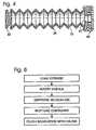
- the end of the shell opposite connector 32includes a passage 42 that is selectively sealed by a closure member in the form of a cap 44, as shown in Fig. 6.
- the shellincludes a circumferential groove 46 that receives a corresponding flange 48 formed on the inside surface of the cap.
- the capis preferably formed of a butyl rubber compound to allow it be fit over the end of the shell and retained thereon.
- the outer perimeter of the capis shaped to form a perimeter seal 50 and sized to fit snuggly within the barrel, similar to the tip on a standard plunger. When the container is placed in the barrel, as shown in Figs. 1-3, the perimeter seal effectively separates the barrel into two regions or cavities: a first region 52 disposed between the closed end and the cap and a second region 54 disposed behind the cap and occupied by the container.
- An inwardly facing cup 56is formed on the end face of the cap.
- the walls of the cupare received in a recess 58 formed in the end of the shell proximal to passage 42.
- a slight outward tilt to the walls of the cup and recessserves to help retain the cap on the end of the shell.
- any pressure created in the fluid in the shelltends to urge the walls of the cup outward to tighten the seal between the cap and shell, thereby preventing the escape of fluid and preventing the cap from being pushed off the end of the shell.
- the bottom of the cupforms a rupture zone 60 that is pressure rupturable, i.e. ruptures when fluid pressure across the rupture zone exceeds some desired level.
- the thickness of the rupture zonemay be varied to control the pressure at which occurs.
- a defectmay be created in the rupture zone to provide a predetermined failure location.
- the defectcan be a cut extending part way through the material of the cap or a series of partial perforations.
- the rupture zoneshould fail at a relatively predictable pressure.
- the pressureshould be readily achievable by finger pressure on the thumb pad of the plunger. It should be noted that any pressure created in the shell is matched by backpressure of the fluid in the first region. Therefore, zone 60 will not rupture until the fluid in the first region is substantially completely expelled.
- the dashed lines in Fig. 6depict the rupture zone after rupture.
- An alternative cap structure 62is shown in Fig. 7 and includes a rupture sheet 64 disposed over passage 42.
- the rupture sheetis preferably formed of a thin sheet of rubber, plastic or non-corrosive metal.
- the rupture sheetis supported and retained against the end of the shell by a seal flange 66 with a central aperture 68 aligned with passage 42. The aperture allows fluid to pass after rupture of the sheet.
- the seal flangeis held in place on the end of the shell by a clamp ring 70 that is crimped over the end of the shell.
- the clamp ringis preferably formed from a thin deformable cylinder of metal, such as used on the end of a medicine vial.
- a seal 72preferably formed of a butyl rubber compound, is disposed over the clamp ring to form a seal with the walls of the barrel, as previously described.
- the clamp ring and sealinclude apertures 74 and 76, respectively, that allow fluid from the container to pass after the sheet is ruptured, as shown by the dashed lines in Fig.6.
- the syringe of the present inventionis preferably pre-loaded or filled with saline or other second fluid at the time of manufacture.
- the plungeris also attached to the container and the resulting assembly is packaged in a sterile condition for shipment.
- the needlemay or may not be attached, depending on the configuration desired.
- the barrel and plunger of the present inventionare preferably unmodified components from a standard syringe design. This eliminates the need to create new and specialized parts for use with a two-fluid syringe.
- the containerbe pre-loaded in the syringe, it should also be understood that the container could be provided as a separate unit for installation and use with an otherwise standard syringe. This variation is facilitated by use of a design that incorporates unmodified parts from a standard syringe.
- Fig. 8depicts the steps involved in using a syringe according to the present invention.
- the operatorselects a pre-loaded syringe package and removes the sterile cmrelope. If necessary, a needle is attached to the barrel.
- the operatorthen loads the desired amount of medicine into the syringe similar to loading a conventional syringe. This is possible because the plunger/container functions like a standard plunger until the medicine in the forward region is expelled and the container is ruptured.
- the operatorcan retract the plunger to load air into the syringe, insert the needle into a medicine vial, push forward on the plunger to inject the air into the vial and then retract the plunger again to withdraw the desired amount of medicine.
- the needleis then inserted into an IV, and the medicine is dispensed by depressing the plunger, as shown by comparison of Figs. 1 and 2.
- the medicineis dispensed, subsequent pressure on the plunger ruptures the cap, releasing the saline or other fluid in the container.
- the plungeris then further depressed to compress the container, as depicted in Fig. 3, and force the secondary fluid out, thereby flushing the medicine.
- the syringe of the present inventionprovides an economical and easy to use solution to the problem of sequentially injecting two fluids.
- the simple operationsaves time and decreases the chances that a health care worker will inadvertently stick themselves with the needle.
Landscapes
- Health & Medical Sciences (AREA)
- Vascular Medicine (AREA)
- Engineering & Computer Science (AREA)
- Anesthesiology (AREA)
- Biomedical Technology (AREA)
- Heart & Thoracic Surgery (AREA)
- Hematology (AREA)
- Life Sciences & Earth Sciences (AREA)
- Animal Behavior & Ethology (AREA)
- General Health & Medical Sciences (AREA)
- Public Health (AREA)
- Veterinary Medicine (AREA)
- Infusion, Injection, And Reservoir Apparatuses (AREA)
- Radiation-Therapy Devices (AREA)
Abstract
Description
- the first opening is selectively sealed by a closure member, the closuremember being adapted to open in response to a pressure differential across theclosure member; and
- the first end is adapted to be received by a coupler in use.
Claims (15)
- A container (28) for use with a syringe (10), the syringe comprising abarrel (12) having an injection port (22) adapted to receive a needle (24), aplunger (28) slidably disposable through an open end of the barrel and a seal(50,72) slidably positionable between the container and the barrel, to form a firstcavity (52) in the barrel with a volume adjustable by moving the container in thebarrel with the plunger, the container comprising:characterised in that:a first end, having a closed rear end wall;a second end;a collapsible shell (30); andat least a first opening at the second end,the first opening is selectively sealed by a closure member (44), theclosure member being adapted to open in response to a pressure differentialacross the closure member; andthe first end is adapted to be received by a coupler in use.
- A container (28) according to claim 1, wherein the closure member (44)opens by rupturing.
- A container (28) according to claim 1 or claim 2, wherein the closuremember (44) includes a rupture sheet (64) disposed over the opening andconfigured to rupture to allow fluid in the container (28) to be expelled.
- A container (28) according to any preceding claim, wherein the closuremember (44) is configured to rupture when pressure is applied to the plunger(38) after a substantially complete portion of the fluid in the first cavity has beenexpelled.
- A container (28) according to any preceding claim, wherein the closuremember (44) includes at least one cut through the closure member, wherein theat least one cut opens in response to a pressure differential across the closure member to provide fluid communication between the container (28) and theinjection port (22).
- A container (28) according to any preceding claim, wherein the container(28) further comprises a coupler (34) disposed between the plunger (38) and therear end wall to connect the plunger to the container.
- A container (28) according to any preceding claim, wherein the closuremember (44) is integrally formed with the seal (50,72).
- A container (28) according to any preceding claim, wherein thecollapsible shell (30) is pleated.
- A container (28) according to any preceding claim, wherein thecollapsible shell (30) is formed generally in the shape of a bellows.
- A container (28) according to any preceding claim, wherein the container(28) includes a connector (34) adapted to be coupled to a correspondingconnector formed on an end of the plunger (38).
- A container (28) according to any preceding claim, further comprising afluid within the container.
- A container (28) according to claim 11, wherein the fluid is saline.
- A container (28) according to any preceding claim, wherein the first cavitycan be emptied without damaging the closure member (44).
- A container (28) according to any preceding claim wherein the closuremember (44) is comprised of an elastomer.
- A multiple-dose syringe (10), comprising:a barrel (12) having a closed end and an open end, the closed endhaving an injection port (22) adapted to receive a needle (24);a plunger (38) slidably disposed through the open end of the barrel; anda container (28) according to any preceding claim.
Applications Claiming Priority (3)
| Application Number | Priority Date | Filing Date | Title |
|---|---|---|---|
| US09/392,870US6270482B1 (en) | 1999-09-09 | 1999-09-09 | Multiple-dose syringe |
| US392870 | 1999-09-09 | ||
| PCT/US2000/024627WO2001017590A1 (en) | 1999-09-09 | 2000-09-07 | Multiple-dose syringe |
Publications (3)
| Publication Number | Publication Date |
|---|---|
| EP1225937A1 EP1225937A1 (en) | 2002-07-31 |
| EP1225937A4 EP1225937A4 (en) | 2002-10-23 |
| EP1225937B1true EP1225937B1 (en) | 2005-07-13 |
Family
ID=23552353
Family Applications (1)
| Application Number | Title | Priority Date | Filing Date |
|---|---|---|---|
| EP00960023AExpired - LifetimeEP1225937B1 (en) | 1999-09-09 | 2000-09-07 | Multiple-dose syringe |
Country Status (6)
| Country | Link |
|---|---|
| US (2) | US6270482B1 (en) |
| EP (1) | EP1225937B1 (en) |
| AT (1) | ATE299383T1 (en) |
| AU (1) | AU7124800A (en) |
| DE (1) | DE60021275T2 (en) |
| WO (1) | WO2001017590A1 (en) |
Families Citing this family (53)
| Publication number | Priority date | Publication date | Assignee | Title |
|---|---|---|---|---|
| US6669689B2 (en) | 1997-02-27 | 2003-12-30 | Cryocath Technologies Inc. | Cryosurgical catheter |
| US6913604B2 (en)* | 1997-02-27 | 2005-07-05 | Cryocath Technologies Inc. | Cryosurgical catheter |
| US7011650B2 (en)* | 1999-09-09 | 2006-03-14 | Paradigm Medical, Llc | Multiple-dose syringe with collapsible container |
| US7850663B2 (en)* | 2001-01-12 | 2010-12-14 | Becton, Dickinson And Company | Medicament microdevice delivery system, cartridge and method of use |
| US7083596B2 (en)* | 2001-06-20 | 2006-08-01 | V. C. Saied | Anesthetizer with automatic needle decommissioning mechanism |
| US6830564B2 (en)* | 2002-01-24 | 2004-12-14 | Robin Scott Gray | Syringe and method of using |
| CA2540657A1 (en)* | 2003-10-20 | 2005-04-28 | Jms Co., Ltd. | Cell handling device, human tissue regeneration composition, and human tissue regeneration method |
| EP2962660A1 (en) | 2004-02-02 | 2016-01-06 | Bimeda Research & Development Limited | Device for treating a teat canal of an animal |
| CN1980614B (en)* | 2004-02-02 | 2011-12-28 | 百美达研究与发展有限公司 | Device for treating animal papillary ducts |
| US9555223B2 (en) | 2004-03-23 | 2017-01-31 | Medtronic Cryocath Lp | Method and apparatus for inflating and deflating balloon catheters |
| US7727228B2 (en) | 2004-03-23 | 2010-06-01 | Medtronic Cryocath Lp | Method and apparatus for inflating and deflating balloon catheters |
| US8491636B2 (en) | 2004-03-23 | 2013-07-23 | Medtronic Cryopath LP | Method and apparatus for inflating and deflating balloon catheters |
| US8066629B2 (en)* | 2005-02-24 | 2011-11-29 | Ethicon Endo-Surgery, Inc. | Apparatus for adjustment and sensing of gastric band pressure |
| US8529517B2 (en)* | 2005-05-02 | 2013-09-10 | Shi Zi Technology, Ltd. | Autoflush syringe |
| US8075533B2 (en)* | 2005-05-02 | 2011-12-13 | Preventiv, Inc. | Autoflush syringe |
| US8936577B2 (en) | 2005-05-02 | 2015-01-20 | Shi Zi Technology, Ltd. | Methods and devices for autoflush syringes |
| US8152710B2 (en) | 2006-04-06 | 2012-04-10 | Ethicon Endo-Surgery, Inc. | Physiological parameter analysis for an implantable restriction device and a data logger |
| US8870742B2 (en) | 2006-04-06 | 2014-10-28 | Ethicon Endo-Surgery, Inc. | GUI for an implantable restriction device and a data logger |
| US8292848B2 (en)* | 2006-07-31 | 2012-10-23 | Bio Quiddity, Inc. | Fluid dispensing device with additive |
| US7607541B2 (en)* | 2006-10-23 | 2009-10-27 | Deborah Girgis | Liquid medication storage and dispensing unit |
| US8021342B2 (en)* | 2006-11-03 | 2011-09-20 | Deborah Girgis | Liquid medication dispenser |
| US8226609B2 (en)* | 2007-06-25 | 2012-07-24 | Bioquiddity, Inc. | Fluid dispenser with additive sub-system |
| US20080319385A1 (en)* | 2007-06-25 | 2008-12-25 | Kriesel Marshall S | Fluid dispenser with additive sub-system |
| US8211059B2 (en)* | 2007-06-25 | 2012-07-03 | Kriesel Marshall S | Fluid dispenser with additive sub-system |
| US9108006B2 (en)* | 2007-08-17 | 2015-08-18 | Novo Nordisk A/S | Medical device with value sensor |
| US8152778B2 (en)* | 2008-09-30 | 2012-04-10 | Tyco Healthcare Group Lp | Device for interfacing with standard luer lock syringes |
| EP2384703A1 (en)* | 2010-05-05 | 2011-11-09 | Bioadhesives Meditech Solutions, S.L. | Device for dispensing a two-component tissue adhesive or sealant |
| US10046106B2 (en) | 2010-10-25 | 2018-08-14 | Bayer Healthcare Llc | Bladder syringe fluid delivery system |
| US9498570B2 (en) | 2010-10-25 | 2016-11-22 | Bayer Healthcare Llc | Bladder syringe fluid delivery system |
| US9314588B2 (en) | 2011-10-28 | 2016-04-19 | Medtronic Cryocath Lp | Systems and methods for variable injection flow |
| US9180252B2 (en) | 2012-04-20 | 2015-11-10 | Bayer Medical Care Inc. | Bellows syringe fluid delivery system |
| DE102012107652A1 (en)* | 2012-08-21 | 2014-03-20 | Astrium Gmbh | Container for the at least largely separate storage and delivery of substances, in particular for storage and delivery in outer space |
| US9814871B2 (en) | 2013-03-15 | 2017-11-14 | Bayer Healthcare Llc | Connector assembly for syringe system |
| AU2014318264B2 (en) | 2013-09-16 | 2018-10-04 | Zoetis Services Llc | Assembly for sequentially delivering substances, and associated methods |
| WO2015071352A1 (en)* | 2013-11-14 | 2015-05-21 | Sfm Medical Devices Gmbh | Syringe for sequential injection of active ingredients |
| ES2873963T3 (en) | 2014-04-25 | 2021-11-04 | Bayer Healthcare Llc | Rolling Diaphragm Syringe |
| US10010708B2 (en)* | 2014-12-20 | 2018-07-03 | Esthetic Education LLC | Microneedle cartridge and nosecone assembly |
| US10933190B2 (en) | 2015-04-24 | 2021-03-02 | Bayer Healthcare Llc | Syringe with rolling diaphragm |
| AU2016359665B2 (en) | 2015-11-25 | 2021-11-04 | Bayer Healthcare Llc | Syringe and connector system |
| AR109649A1 (en) | 2016-09-16 | 2019-01-09 | Bayer Healthcare Llc | PRESSURE SHIRT WITH SYRINGE RETAINING ELEMENT |
| CA3040484A1 (en) | 2016-10-17 | 2018-04-26 | Bayer Healthcare Llc | Fluid injector with syringe engagement mechanism |
| CN109843355B (en) | 2016-10-17 | 2022-03-25 | 拜耳医药保健有限公司 | Fluid Syringe with Syringe Engagement Mechanism |
| WO2019055497A1 (en) | 2017-09-13 | 2019-03-21 | Bayer Healthcare Llc | Sliding syringe cap for separate filling and delivery |
| AU2019340438A1 (en) | 2018-09-11 | 2021-03-04 | Bayer Healthcare Llc | Syringe retention feature for fluid injector system |
| US11439768B2 (en)* | 2019-07-17 | 2022-09-13 | Wagner Florexil | Compartmentalized syringe for combined medicine and flush solution |
| US11918775B2 (en) | 2019-09-10 | 2024-03-05 | Bayer Healthcare Llc | Pressure jackets and syringe retention features for angiography fluid injectors |
| CR20220394A (en) | 2020-02-21 | 2023-01-23 | Bayer Healthcare Llc | Fluid path connectors for medical fluid delivery |
| PT4110452T (en) | 2020-02-28 | 2025-01-14 | Bayer Healthcare Llc | FLUID MIXING SET |
| WO2021188460A1 (en) | 2020-03-16 | 2021-09-23 | Bayer Healthcare Llc | Stopcock apparatus for angiography injector fluid paths |
| CN115697435A (en) | 2020-06-18 | 2023-02-03 | 拜耳医药保健有限责任公司 | Inline Bubble Suspension Device for the Fluid Path of Angiography Injectors |
| RS66861B1 (en) | 2020-08-11 | 2025-06-30 | Bayer Healthcare Llc | Features for angiography syringe |
| CN116547022A (en) | 2020-12-01 | 2023-08-04 | 拜耳医药保健有限责任公司 | Cassette for holding fluid path components of a fluid injector system |
| WO2022265695A1 (en) | 2021-06-17 | 2022-12-22 | Bayer Healthcare Llc | System and method for detecting fluid type in tubing for fluid injector apparatus |
Citations (1)
| Publication number | Priority date | Publication date | Assignee | Title |
|---|---|---|---|---|
| US2950717A (en)* | 1955-03-21 | 1960-08-30 | R K Price Associates Inc | Ampules |
Family Cites Families (11)
| Publication number | Priority date | Publication date | Assignee | Title |
|---|---|---|---|---|
| US2939459A (en)* | 1957-01-11 | 1960-06-07 | Jorge A Lazarte | Tandem syringe |
| US3911916A (en)* | 1971-10-29 | 1975-10-14 | Peter A Stevens | Sequential injection syringe |
| FR2237643B1 (en) | 1973-07-17 | 1978-03-17 | Steiner Maurice | |
| US4215701A (en)* | 1978-08-21 | 1980-08-05 | Concord Laboratories, Inc. | Elastomeric plunger tip for a syringe |
| DE3618318A1 (en)* | 1986-05-30 | 1987-12-03 | Rau Roland | Hypodermic syringe |
| US4715854A (en) | 1986-07-17 | 1987-12-29 | Vaillancourt Vincent L | Multidose disposable syringe and method of filling same |
| US5281198A (en)* | 1992-05-04 | 1994-01-25 | Habley Medical Technology Corporation | Pharmaceutical component-mixing delivery assembly |
| US5308322A (en)* | 1993-04-19 | 1994-05-03 | Tennican Patrick O | Central venous catheter access system |
| US5489267A (en)* | 1994-01-03 | 1996-02-06 | Moreno; Saul | Double chamber disposable syringe |
| FR2750051A1 (en) | 1996-06-21 | 1997-12-26 | Debiotech Sa | Medical syringe comprise one or more free pistons of elastic material |
| US6077252A (en)* | 1997-09-17 | 2000-06-20 | Siegel; Robert | Single or multiple dose syringe |
- 1999
- 1999-09-09USUS09/392,870patent/US6270482B1/ennot_activeExpired - Fee Related
- 2000
- 2000-09-07DEDE60021275Tpatent/DE60021275T2/ennot_activeExpired - Lifetime
- 2000-09-07ATAT00960023Tpatent/ATE299383T1/ennot_activeIP Right Cessation
- 2000-09-07WOPCT/US2000/024627patent/WO2001017590A1/enactiveIP Right Grant
- 2000-09-07EPEP00960023Apatent/EP1225937B1/ennot_activeExpired - Lifetime
- 2000-09-07AUAU71248/00Apatent/AU7124800A/ennot_activeAbandoned
- 2001
- 2001-08-06USUS09/923,756patent/US6558358B2/ennot_activeExpired - Fee Related
Patent Citations (1)
| Publication number | Priority date | Publication date | Assignee | Title |
|---|---|---|---|---|
| US2950717A (en)* | 1955-03-21 | 1960-08-30 | R K Price Associates Inc | Ampules |
Also Published As
| Publication number | Publication date |
|---|---|
| DE60021275D1 (en) | 2005-08-18 |
| AU7124800A (en) | 2001-04-10 |
| EP1225937A4 (en) | 2002-10-23 |
| US20020029019A1 (en) | 2002-03-07 |
| US6558358B2 (en) | 2003-05-06 |
| WO2001017590A1 (en) | 2001-03-15 |
| US6270482B1 (en) | 2001-08-07 |
| DE60021275T2 (en) | 2005-12-22 |
| EP1225937A1 (en) | 2002-07-31 |
| ATE299383T1 (en) | 2005-07-15 |
Similar Documents
| Publication | Publication Date | Title |
|---|---|---|
| EP1225937B1 (en) | Multiple-dose syringe | |
| US7011650B2 (en) | Multiple-dose syringe with collapsible container | |
| US11458253B2 (en) | Medicant injection device | |
| JP2930201B2 (en) | Stopper assembly with bypass for use in a multi-chamber syringe barrel | |
| US6681810B2 (en) | Filling device for a needleless injector cartridge | |
| JP4682850B2 (en) | Prefilled syringe | |
| US6174304B1 (en) | Filling device for a needless injector cartridge | |
| US20020091361A1 (en) | Multiple-dose syringe | |
| US3527215A (en) | Syringe construction having internal bladder | |
| US7267668B2 (en) | Disposable syringe and cartridge with pneumatic chamber | |
| EP0701833A1 (en) | Plungerless Syringe | |
| US20050177100A1 (en) | Dual chamber mixing syringe and method for use | |
| JP2002515268A (en) | Syringe assembly | |
| CS226001B2 (en) | Syringe | |
| US6245041B1 (en) | Fluid dispenser with fill adapter | |
| JP2007185319A5 (en) | ||
| KR20000070842A (en) | Applicator for semi-solid medications | |
| CN103648559B (en) | Modular gas activates retractable needle assembly | |
| PL203189B1 (en) | Medical device | |
| WO1993021986A2 (en) | Applicator for semisolid medications | |
| JPH06190038A (en) | Subcutaneous syringe | |
| US5413564A (en) | Predetermined dosage hypodermic syringe system | |
| CN106232160B (en) | ejector | |
| US20020035351A1 (en) | Single barrel double chamber syringe | |
| US20080249462A1 (en) | Disposable Dispensers for Personal Use |
Legal Events
| Date | Code | Title | Description |
|---|---|---|---|
| PUAI | Public reference made under article 153(3) epc to a published international application that has entered the european phase | Free format text:ORIGINAL CODE: 0009012 | |
| 17P | Request for examination filed | Effective date:20020315 | |
| AK | Designated contracting states | Kind code of ref document:A1 Designated state(s):AT BE CH CY DE DK ES FI FR GB GR IE IT LI LU MC NL PT SE | |
| AX | Request for extension of the european patent | Free format text:AL;LT;LV;MK;RO;SI | |
| A4 | Supplementary search report drawn up and despatched | Effective date:20020911 | |
| AK | Designated contracting states | Kind code of ref document:A4 Designated state(s):AT BE CH CY DE DK ES FI FR GB GR IE IT LI LU MC NL PT SE | |
| 17Q | First examination report despatched | Effective date:20030127 | |
| RAP1 | Party data changed (applicant data changed or rights of an application transferred) | Owner name:PARADIGM MEDICAL, LLC | |
| GRAP | Despatch of communication of intention to grant a patent | Free format text:ORIGINAL CODE: EPIDOSNIGR1 | |
| GRAS | Grant fee paid | Free format text:ORIGINAL CODE: EPIDOSNIGR3 | |
| GRAA | (expected) grant | Free format text:ORIGINAL CODE: 0009210 | |
| AK | Designated contracting states | Kind code of ref document:B1 Designated state(s):AT BE CH CY DE DK ES FI FR GB GR IE IT LI LU MC NL PT SE | |
| PG25 | Lapsed in a contracting state [announced via postgrant information from national office to epo] | Ref country code:IT Free format text:LAPSE BECAUSE OF FAILURE TO SUBMIT A TRANSLATION OF THE DESCRIPTION OR TO PAY THE FEE WITHIN THE PRESCRIBED TIME-LIMIT;WARNING: LAPSES OF ITALIAN PATENTS WITH EFFECTIVE DATE BEFORE 2007 MAY HAVE OCCURRED AT ANY TIME BEFORE 2007. THE CORRECT EFFECTIVE DATE MAY BE DIFFERENT FROM THE ONE RECORDED. Effective date:20050713 Ref country code:BE Free format text:LAPSE BECAUSE OF FAILURE TO SUBMIT A TRANSLATION OF THE DESCRIPTION OR TO PAY THE FEE WITHIN THE PRESCRIBED TIME-LIMIT Effective date:20050713 Ref country code:NL Free format text:LAPSE BECAUSE OF FAILURE TO SUBMIT A TRANSLATION OF THE DESCRIPTION OR TO PAY THE FEE WITHIN THE PRESCRIBED TIME-LIMIT Effective date:20050713 Ref country code:AT Free format text:LAPSE BECAUSE OF FAILURE TO SUBMIT A TRANSLATION OF THE DESCRIPTION OR TO PAY THE FEE WITHIN THE PRESCRIBED TIME-LIMIT Effective date:20050713 Ref country code:CH Free format text:LAPSE BECAUSE OF FAILURE TO SUBMIT A TRANSLATION OF THE DESCRIPTION OR TO PAY THE FEE WITHIN THE PRESCRIBED TIME-LIMIT Effective date:20050713 Ref country code:FI Free format text:LAPSE BECAUSE OF FAILURE TO SUBMIT A TRANSLATION OF THE DESCRIPTION OR TO PAY THE FEE WITHIN THE PRESCRIBED TIME-LIMIT Effective date:20050713 Ref country code:LI Free format text:LAPSE BECAUSE OF FAILURE TO SUBMIT A TRANSLATION OF THE DESCRIPTION OR TO PAY THE FEE WITHIN THE PRESCRIBED TIME-LIMIT Effective date:20050713 | |
| REG | Reference to a national code | Ref country code:GB Ref legal event code:FG4D | |
| REG | Reference to a national code | Ref country code:CH Ref legal event code:EP | |
| REG | Reference to a national code | Ref country code:IE Ref legal event code:FG4D | |
| REF | Corresponds to: | Ref document number:60021275 Country of ref document:DE Date of ref document:20050818 Kind code of ref document:P | |
| PG25 | Lapsed in a contracting state [announced via postgrant information from national office to epo] | Ref country code:IE Free format text:LAPSE BECAUSE OF NON-PAYMENT OF DUE FEES Effective date:20050907 Ref country code:CY Free format text:LAPSE BECAUSE OF FAILURE TO SUBMIT A TRANSLATION OF THE DESCRIPTION OR TO PAY THE FEE WITHIN THE PRESCRIBED TIME-LIMIT Effective date:20050907 | |
| PG25 | Lapsed in a contracting state [announced via postgrant information from national office to epo] | Ref country code:MC Free format text:LAPSE BECAUSE OF NON-PAYMENT OF DUE FEES Effective date:20050930 Ref country code:LU Free format text:LAPSE BECAUSE OF NON-PAYMENT OF DUE FEES Effective date:20050930 | |
| PG25 | Lapsed in a contracting state [announced via postgrant information from national office to epo] | Ref country code:GR Free format text:LAPSE BECAUSE OF FAILURE TO SUBMIT A TRANSLATION OF THE DESCRIPTION OR TO PAY THE FEE WITHIN THE PRESCRIBED TIME-LIMIT Effective date:20051013 Ref country code:DK Free format text:LAPSE BECAUSE OF FAILURE TO SUBMIT A TRANSLATION OF THE DESCRIPTION OR TO PAY THE FEE WITHIN THE PRESCRIBED TIME-LIMIT Effective date:20051013 Ref country code:SE Free format text:LAPSE BECAUSE OF FAILURE TO SUBMIT A TRANSLATION OF THE DESCRIPTION OR TO PAY THE FEE WITHIN THE PRESCRIBED TIME-LIMIT Effective date:20051013 | |
| PG25 | Lapsed in a contracting state [announced via postgrant information from national office to epo] | Ref country code:ES Free format text:LAPSE BECAUSE OF FAILURE TO SUBMIT A TRANSLATION OF THE DESCRIPTION OR TO PAY THE FEE WITHIN THE PRESCRIBED TIME-LIMIT Effective date:20051024 | |
| PG25 | Lapsed in a contracting state [announced via postgrant information from national office to epo] | Ref country code:PT Free format text:LAPSE BECAUSE OF FAILURE TO SUBMIT A TRANSLATION OF THE DESCRIPTION OR TO PAY THE FEE WITHIN THE PRESCRIBED TIME-LIMIT Effective date:20051219 | |
| NLV1 | Nl: lapsed or annulled due to failure to fulfill the requirements of art. 29p and 29m of the patents act | ||
| REG | Reference to a national code | Ref country code:CH Ref legal event code:PL | |
| ET | Fr: translation filed | ||
| PLBE | No opposition filed within time limit | Free format text:ORIGINAL CODE: 0009261 | |
| STAA | Information on the status of an ep patent application or granted ep patent | Free format text:STATUS: NO OPPOSITION FILED WITHIN TIME LIMIT | |
| REG | Reference to a national code | Ref country code:IE Ref legal event code:MM4A | |
| 26N | No opposition filed | Effective date:20060418 | |
| PGFP | Annual fee paid to national office [announced via postgrant information from national office to epo] | Ref country code:FR Payment date:20101014 Year of fee payment:11 | |
| PGFP | Annual fee paid to national office [announced via postgrant information from national office to epo] | Ref country code:DE Payment date:20101006 Year of fee payment:11 | |
| REG | Reference to a national code | Ref country code:FR Ref legal event code:ST Effective date:20120531 | |
| REG | Reference to a national code | Ref country code:DE Ref legal event code:R119 Ref document number:60021275 Country of ref document:DE Effective date:20120403 | |
| PG25 | Lapsed in a contracting state [announced via postgrant information from national office to epo] | Ref country code:DE Free format text:LAPSE BECAUSE OF NON-PAYMENT OF DUE FEES Effective date:20120403 | |
| PG25 | Lapsed in a contracting state [announced via postgrant information from national office to epo] | Ref country code:FR Free format text:LAPSE BECAUSE OF NON-PAYMENT OF DUE FEES Effective date:20110930 | |
| PGFP | Annual fee paid to national office [announced via postgrant information from national office to epo] | Ref country code:GB Payment date:20150331 Year of fee payment:15 | |
| GBPC | Gb: european patent ceased through non-payment of renewal fee | Effective date:20150907 | |
| PG25 | Lapsed in a contracting state [announced via postgrant information from national office to epo] | Ref country code:GB Free format text:LAPSE BECAUSE OF NON-PAYMENT OF DUE FEES Effective date:20150907 |