EP1225933B1 - Retractable dental syringe - Google Patents
Retractable dental syringeDownload PDFInfo
- Publication number
- EP1225933B1 EP1225933B1EP00963757AEP00963757AEP1225933B1EP 1225933 B1EP1225933 B1EP 1225933B1EP 00963757 AEP00963757 AEP 00963757AEP 00963757 AEP00963757 AEP 00963757AEP 1225933 B1EP1225933 B1EP 1225933B1
- Authority
- EP
- European Patent Office
- Prior art keywords
- carpule
- needle
- plunger
- housing
- dental syringe
- Prior art date
- Legal status (The legal status is an assumption and is not a legal conclusion. Google has not performed a legal analysis and makes no representation as to the accuracy of the status listed.)
- Expired - Lifetime
Links
- 239000012530fluidSubstances0.000claimsabstractdescription30
- 238000002347injectionMethods0.000claimsabstractdescription16
- 239000007924injectionSubstances0.000claimsabstractdescription16
- 238000004891communicationMethods0.000claimsdescription3
- 230000000881depressing effectEffects0.000claimsdescription2
- 230000007246mechanismEffects0.000abstractdescription8
- 230000000994depressogenic effectEffects0.000abstractdescription5
- 239000003814drugSubstances0.000abstractdescription5
- 210000003813thumbAnatomy0.000abstractdescription5
- 208000012266Needlestick injuryDiseases0.000description3
- 229940079593drugDrugs0.000description3
- 239000000853adhesiveSubstances0.000description2
- 230000001070adhesive effectEffects0.000description2
- 230000007812deficiencyEffects0.000description2
- 235000012489doughnutsNutrition0.000description2
- 239000011521glassSubstances0.000description2
- 239000004033plasticSubstances0.000description2
- 229920003023plasticPolymers0.000description2
- 229940071643prefilled syringeDrugs0.000description2
- 230000002028prematureEffects0.000description2
- 208000030507AIDSDiseases0.000description1
- 208000035473Communicable diseaseDiseases0.000description1
- 239000004743PolypropyleneSubstances0.000description1
- 230000009286beneficial effectEffects0.000description1
- 230000008859changeEffects0.000description1
- 230000006378damageEffects0.000description1
- 230000000694effectsEffects0.000description1
- 230000008014freezingEffects0.000description1
- 238000007710freezingMethods0.000description1
- 230000006872improvementEffects0.000description1
- 239000012678infectious agentSubstances0.000description1
- 238000004519manufacturing processMethods0.000description1
- 239000000463materialSubstances0.000description1
- 238000002483medicationMethods0.000description1
- 239000012528membraneSubstances0.000description1
- 238000012986modificationMethods0.000description1
- 230000004048modificationEffects0.000description1
- -1polypropylenePolymers0.000description1
- 229920001155polypropylenePolymers0.000description1
- 230000001681protective effectEffects0.000description1
- 238000007789sealingMethods0.000description1
- 238000003466weldingMethods0.000description1
Images


Classifications
- A—HUMAN NECESSITIES
- A61—MEDICAL OR VETERINARY SCIENCE; HYGIENE
- A61M—DEVICES FOR INTRODUCING MEDIA INTO, OR ONTO, THE BODY; DEVICES FOR TRANSDUCING BODY MEDIA OR FOR TAKING MEDIA FROM THE BODY; DEVICES FOR PRODUCING OR ENDING SLEEP OR STUPOR
- A61M5/00—Devices for bringing media into the body in a subcutaneous, intra-vascular or intramuscular way; Accessories therefor, e.g. filling or cleaning devices, arm-rests
- A61M5/178—Syringes
- A61M5/31—Details
- A61M5/32—Needles; Details of needles pertaining to their connection with syringe or hub; Accessories for bringing the needle into, or holding the needle on, the body; Devices for protection of needles
- A61M5/3205—Apparatus for removing or disposing of used needles or syringes, e.g. containers; Means for protection against accidental injuries from used needles
- A61M5/321—Means for protection against accidental injuries by used needles
- A61M5/322—Retractable needles, i.e. disconnected from and withdrawn into the syringe barrel by the piston
- A61M5/3232—Semi-automatic needle retraction, i.e. in which triggering of the needle retraction requires a deliberate action by the user, e.g. manual release of spring-biased retraction means
- A—HUMAN NECESSITIES
- A61—MEDICAL OR VETERINARY SCIENCE; HYGIENE
- A61M—DEVICES FOR INTRODUCING MEDIA INTO, OR ONTO, THE BODY; DEVICES FOR TRANSDUCING BODY MEDIA OR FOR TAKING MEDIA FROM THE BODY; DEVICES FOR PRODUCING OR ENDING SLEEP OR STUPOR
- A61M5/00—Devices for bringing media into the body in a subcutaneous, intra-vascular or intramuscular way; Accessories therefor, e.g. filling or cleaning devices, arm-rests
- A61M5/178—Syringes
- A61M5/24—Ampoule syringes, i.e. syringes with needle for use in combination with replaceable ampoules or carpules, e.g. automatic
- A—HUMAN NECESSITIES
- A61—MEDICAL OR VETERINARY SCIENCE; HYGIENE
- A61M—DEVICES FOR INTRODUCING MEDIA INTO, OR ONTO, THE BODY; DEVICES FOR TRANSDUCING BODY MEDIA OR FOR TAKING MEDIA FROM THE BODY; DEVICES FOR PRODUCING OR ENDING SLEEP OR STUPOR
- A61M5/00—Devices for bringing media into the body in a subcutaneous, intra-vascular or intramuscular way; Accessories therefor, e.g. filling or cleaning devices, arm-rests
- A61M5/178—Syringes
- A61M5/31—Details
- A61M5/32—Needles; Details of needles pertaining to their connection with syringe or hub; Accessories for bringing the needle into, or holding the needle on, the body; Devices for protection of needles
- A61M5/3205—Apparatus for removing or disposing of used needles or syringes, e.g. containers; Means for protection against accidental injuries from used needles
- A61M5/321—Means for protection against accidental injuries by used needles
- A61M5/322—Retractable needles, i.e. disconnected from and withdrawn into the syringe barrel by the piston
- A61M5/3234—Fully automatic needle retraction, i.e. in which triggering of the needle does not require a deliberate action by the user
- A—HUMAN NECESSITIES
- A61—MEDICAL OR VETERINARY SCIENCE; HYGIENE
- A61M—DEVICES FOR INTRODUCING MEDIA INTO, OR ONTO, THE BODY; DEVICES FOR TRANSDUCING BODY MEDIA OR FOR TAKING MEDIA FROM THE BODY; DEVICES FOR PRODUCING OR ENDING SLEEP OR STUPOR
- A61M5/00—Devices for bringing media into the body in a subcutaneous, intra-vascular or intramuscular way; Accessories therefor, e.g. filling or cleaning devices, arm-rests
- A61M5/178—Syringes
- A61M5/24—Ampoule syringes, i.e. syringes with needle for use in combination with replaceable ampoules or carpules, e.g. automatic
- A61M2005/2403—Ampoule inserted into the ampoule holder
- A61M2005/2407—Ampoule inserted into the ampoule holder from the rear
- A—HUMAN NECESSITIES
- A61—MEDICAL OR VETERINARY SCIENCE; HYGIENE
- A61M—DEVICES FOR INTRODUCING MEDIA INTO, OR ONTO, THE BODY; DEVICES FOR TRANSDUCING BODY MEDIA OR FOR TAKING MEDIA FROM THE BODY; DEVICES FOR PRODUCING OR ENDING SLEEP OR STUPOR
- A61M5/00—Devices for bringing media into the body in a subcutaneous, intra-vascular or intramuscular way; Accessories therefor, e.g. filling or cleaning devices, arm-rests
- A61M5/178—Syringes
- A61M5/24—Ampoule syringes, i.e. syringes with needle for use in combination with replaceable ampoules or carpules, e.g. automatic
- A61M2005/2403—Ampoule inserted into the ampoule holder
- A61M2005/2414—Ampoule inserted into the ampoule holder from the side
- A—HUMAN NECESSITIES
- A61—MEDICAL OR VETERINARY SCIENCE; HYGIENE
- A61M—DEVICES FOR INTRODUCING MEDIA INTO, OR ONTO, THE BODY; DEVICES FOR TRANSDUCING BODY MEDIA OR FOR TAKING MEDIA FROM THE BODY; DEVICES FOR PRODUCING OR ENDING SLEEP OR STUPOR
- A61M5/00—Devices for bringing media into the body in a subcutaneous, intra-vascular or intramuscular way; Accessories therefor, e.g. filling or cleaning devices, arm-rests
- A61M5/178—Syringes
- A61M5/31—Details
- A61M2005/3117—Means preventing contamination of the medicament compartment of a syringe
- A61M2005/3121—Means preventing contamination of the medicament compartment of a syringe via the proximal end of a syringe, i.e. syringe end opposite to needle cannula mounting end
- A—HUMAN NECESSITIES
- A61—MEDICAL OR VETERINARY SCIENCE; HYGIENE
- A61M—DEVICES FOR INTRODUCING MEDIA INTO, OR ONTO, THE BODY; DEVICES FOR TRANSDUCING BODY MEDIA OR FOR TAKING MEDIA FROM THE BODY; DEVICES FOR PRODUCING OR ENDING SLEEP OR STUPOR
- A61M5/00—Devices for bringing media into the body in a subcutaneous, intra-vascular or intramuscular way; Accessories therefor, e.g. filling or cleaning devices, arm-rests
- A61M5/178—Syringes
- A61M5/31—Details
- A61M5/3129—Syringe barrels
- A61M5/3137—Specially designed finger grip means, e.g. for easy manipulation of the syringe rod
- A—HUMAN NECESSITIES
- A61—MEDICAL OR VETERINARY SCIENCE; HYGIENE
- A61M—DEVICES FOR INTRODUCING MEDIA INTO, OR ONTO, THE BODY; DEVICES FOR TRANSDUCING BODY MEDIA OR FOR TAKING MEDIA FROM THE BODY; DEVICES FOR PRODUCING OR ENDING SLEEP OR STUPOR
- A61M5/00—Devices for bringing media into the body in a subcutaneous, intra-vascular or intramuscular way; Accessories therefor, e.g. filling or cleaning devices, arm-rests
- A61M5/50—Devices for bringing media into the body in a subcutaneous, intra-vascular or intramuscular way; Accessories therefor, e.g. filling or cleaning devices, arm-rests having means for preventing re-use, or for indicating if defective, used, tampered with or unsterile
- A61M5/5013—Means for blocking the piston or the fluid passageway to prevent illegal refilling of a syringe
- A61M5/502—Means for blocking the piston or the fluid passageway to prevent illegal refilling of a syringe for blocking the piston
- A—HUMAN NECESSITIES
- A61—MEDICAL OR VETERINARY SCIENCE; HYGIENE
- A61M—DEVICES FOR INTRODUCING MEDIA INTO, OR ONTO, THE BODY; DEVICES FOR TRANSDUCING BODY MEDIA OR FOR TAKING MEDIA FROM THE BODY; DEVICES FOR PRODUCING OR ENDING SLEEP OR STUPOR
- A61M5/00—Devices for bringing media into the body in a subcutaneous, intra-vascular or intramuscular way; Accessories therefor, e.g. filling or cleaning devices, arm-rests
- A61M5/50—Devices for bringing media into the body in a subcutaneous, intra-vascular or intramuscular way; Accessories therefor, e.g. filling or cleaning devices, arm-rests having means for preventing re-use, or for indicating if defective, used, tampered with or unsterile
- A61M5/508—Means for preventing re-use by disrupting the piston seal, e.g. by puncturing
Definitions
- the present inventionis a retractable medical device, more particularly, a retractable device that employs a removable medicine container that is well suited for dental use.
- syringeswhich employ a pre-filled cartridge of fluid medication and a double ended hypodermic needle communicating with the cartridge for injecting the contents of the cartridge.
- the pre-filled syringe cartridgesare referred to as "carpules". They are typically cylindrical tubes with a puncturable membrane in front and a piston seal at the rear which is pressed forward by some form of plunger. The most common of these are the carpule syringes used by dentists in freezing the gums of their patients prior to their performing dental work on their teeth.
- the syringe enclosures with which such pre-filled syringe cartridges are usedare not easily capable of retracting the needle into a protective enclosure to avoid inadvertent and potentially harmful needle sticks. Consequently, most syringes used for this purpose by dentists have a fixed needle which must be sheathed.
- a retractable dental syringe with the features cited in the preamble of claim 1is described in WO99/44653 A1 .
- An elongated tubular housingcomprising a retraction mechanism and a needle holder embodied in a front portion of housing is configured to receive a carpule.
- the slidable front seal of the carpuleis mounted on the needle holder.
- the outer wall of the carpuleis spaced apart from the inner surface of the tubular housing.
- Fluid contained in the carpulecan be injected by actuating a pressure on a plunger forcing an inner wall of the plunger to make contact with an outer rim portion of piston seal of carpule to move the pistons seal in the direction of the front seal.
- the outer wallis longer than the inner wall which makes contact with the push ring, holding the needle holder in position, at approximately the same time as core part of the piston seal reaches the front seal of the carpule.
- the present inventionis a single use retractable medical device which employ a modified carpule having a sliding piston seal in back and a sliding seal in front.
- the retractable medical deviceis a dental syringe and one embodiment employs a thumb ring at the back of the plunger as is typical with dental syringes.
- the syringeis designed to retract after the injection by the simple expedient of continued depression of the plunger without moving the syringe away from the patient.
- the retraction parts and most of the needleare retracted into the carpule. All of the needle is retracted into the housing instantaneously upon depression of the plunger after the injection.
- the carpulemay be unconventional mainly in the closures at the front and back end.
- the carpulehas a cylindrical wall defining a fluid chamber and a front end with an opening into the fluid chamber and an open back end.
- a slidable front sealis lodged in the opening of the front end.
- the conventional carpulehas no need for a sliding seal to cover the opening of the front end which is punctured by a rearwardly extending needle when the carpule is inserted.
- the modified carpulemay have a two-part sliding piston seal lodged in the open back end.
- the piston sealmay comprise an outer rim portion in sliding sealed contact with the wall of the fluid chamber and a slidably removable core portion.
- the sliding piston sealis moved by a plunger to the front of the fluid chamber to dispense all fluid.
- the sliding front sealremoves the core of the piston seal and traverses through the rim portion to enter the chamber along with following portions of a retraction mechanism.
- the retractable medical devicehas a tubular housing which may have a wall defining a front end portion, a main body portion, an open back end and an inner surface defining a hollow interior.
- a retraction mechanismis mounted in the front end portion of the housing.
- the retraction mechanismmay comprise a needle holder having an elongated body with a front, a back and a widened part of the body spaced behind the front. Needle portions extend from the front and back of the needle holder.
- a springis mounted under the widened part of the needle holder to apply retraction force thereto.
- a releasable "push ring”may be grippingly mounted around the widened part of the needle holder along a longitudinal interface.
- the push ringextends radially outwardly to the inner wall of the housing. Outer edges of the push ring are preferably in sliding gripping contact with the housing to hold the needle holder in place against the retraction force provided by the spring.
- the housing wallmay be provided with stops behind the push ring to prevent rearward motion of the push ring and retraction mechanism.
- One form of push ringis a separable member shaped like a disc with a relatively straight walled opening in the center and a rounded outer edge.
- separable memberis essentially an "O" ring which is donut shaped or still further a donut shaped "O" ring with a relatively straight walled central opening and a curved outer edge.
- the push ring/separable member holding the needle in placeis not required to perform a sealing function for fluid due to the fact that the carpule holds the medicinal fluid. This means that the push ring/separable member could have a hub and spoke design or segmented structure of many different kinds.
- a carpule of the type described abovemay be inserted into the housing with the front seal in contact with the back end of the needle holder and punctured by the needle.
- the front of the carpulefaces the push ring.
- the carpuleis adapted to substantially occupy the space within the tubular housing with the mouth of the carpule positioned to remove a releasable part from the retractable needle structure by moving forward.
- the depressible plungerenters the tubular housing from the rear and empties the carpule by moving the rear seal forward to an end-of-injection position of the two part seal.
- the plungerpushes against one part of the two part seal which has previously been described as a rim portion.
- the plungeris received entirely within the carpule.
- the releasable and separable part of the needle holding structuremay be the "0" ring embodiment or the disc like member with a relatively straight walled opening in the center and a rounded outer edge.
- the partsare relatively uncomplicated and subject to mass production and automated assembly.
- the push ringmay be assembled with the unneedled needle holder in an upright position, the spring placed on the needle holder and the housing dropped over the assembled parts to compress the spring as the push ring and needle holder is moved forward.
- the needlecan be inserted from the front.
- Thisis the first practical retractable dental carpule syringe which retracts by continuation of the same motion used for injection and which retracts the needle directly from tissue to eliminate risk of needle stick with a contaminated needle. It uniquely employs the used carpule to receive the contaminated needle.
- syringe 10has an elongated tubular housing 120.
- Tubular housing 120has an elongated wall 122 forming a front portion 124, an intermediate portion 126 and a rear portion 128.
- Tubular housing 20is adapted to accept a carpule 130.
- Carpule 130differs from carpule 30 in that it is sized to substantially occupy intermediate portion 126 of housing 120.
- Wall 122 of carpule 130preferably lies substantially adjacent the inside surface of wall 122 in the intermediate portion of the housing.
- Carpule 130has a mouth 134, front seal 136 and two part rear seal 138.
- a needle structure 140is retractably mounted in front portion 124 of housing 120.
- a necked in or reduced diameter portion 142 of front portion 124releaseably engages a releasable part 144 mounted in line with mouth 134 of carpule 130.
- Rear end portion 128 of tubular housing 120includes a grip 146 which is used in combination with a thumb ring 148 of a depressible plunger 150.
- Plunger 150slidingly enters housing 120 through opening 152 in rear portion 128.
- Plunger 150has a front end portion 154 having a hooked front 156 which can be seen to selectively engage one part of two part rear seal 138. Forward movement of seal 138 by means of plunger 150 is calculated to move the fluid from fluid chamber 158 of carpule 130 through needle 160 of needle structure 140.
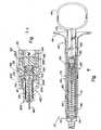
- Figures 2 and 3 in larger scaleshow more details of the structure of syringe 10" shown in Figure 1.
- Figures 2 and 3show the position of syringe 10" at the end-of-injection position.
- plunger 150has been depressed forward toward needle structure 140 thereby moving two part seal 138 until it comes in contact with front seal 136.
- plunger 150has an elongated hollow tubular portion 162 which slides in proximity along the inside surface of wall 132 of carpule 130.
- a rear portion of plunger 150may consist of a set of cross-shaped flanges 164 which may be equipped with unidirectional ramped stops 166 which engage an edge 168 at a change of diameter of rear portion 128.
- Unidirectional stops 166prevent removal of the plunger 150 after the contents of carpule 130 have been emptied through needle 160. As this is a one use syringe, stops prevent disassembly by preventing removal of plunger 150 after syringe 10" has been used.
- retractable needle holding structure 140has a needle holder 170 having a needle holder body portion 172 having a widened part 174 comprising the head of the needle holder.
- Double ended needleor two oppositely pointed needles in fluid communication
- plunger 150When plunger 150 is depressed, fluid in chamber 158 is discharged through needle 160.
- Widened part 174 of needle body 172may be provided with an annular rim (or spaced rim portions) which tends to serve as a projection which operates in cooperation with annular rim 180 (which may comprise rim segments) on the inner wall of necked in portion 142 of housing wall 122.
- the embodiment shownemploys a separable member in the form of an "O" ring made of a material which is compressible.
- the cooperating constrictions 178, 180ensure that the "O" ring 144 must be compressed in order to allow needle body 172 to move rearwardly under the influence of compressed spring 47. It should be considered within the scope of the invention to have a separable part (144) which is a breakaway part or that an adhesive or some form of tenuous welding, such as by ultrasonics, could be used to temporarily connect the separable part with the needle holder.
- front seal 136comprises two interlocking parts comprising a cup shaped member 182 with the open part of the cup facing rearwardly and the bottom of the cup in contact with the top 198 of head 174 of needle body 172.
- a grommet-like member 184is forced into the opening of cup shaped member 182 to slightly spread it and provide a seal with the inside opening of mouth 134.
- cup member 182may include a rim 186 which may occupy a slight depression 188 in the otherwise smooth wall of mouth 134. The combination of rim 186 and depression 188 can have the beneficial effect of increasing frictional resistance to prevent premature removal of sliding seal 136 when plunger 150 is depressed to discharge fluid from carpule 130.
- Sliding rear seal 138has a removable core portion 190 and a slideable rim portion 192 wherein rim portion 192 is engaged by front 156 of plunger 150.
- Core portion 190may include a land 194 wider than the rest of core 190 to help control the amount of friction required to remove core 190 from rim 192.
- Plunger 150has pushed the rear seal forwardly into contact with the front seal. Only core portion 190 is in line with front seal 134 for dislodgment. The smaller diameter of mouth 134 creates a ledge 196 which prevents further forward movement of the rear seal rim member. Cup portion 182 is bottomed against top 198 of needle holding body 172 which in turn is bottomed in the front 200 of a further constricted portion of tubular body 120.
- FIG. 3Aillustrates a variation of the structure just described.
- a slightly modified form of a retractably mounted needle structure 140is structure 140'.
- Rear seal 138 and front seal 136are slidingly mounted respectively in carpule 130 and opening 202 of mouth 134 as in the previous figures.
- Needle 160is still fixed in needle body portion 172 which is bottomed in the front 200 of housing 120.
- Spring 47is compressed under a widened head portion 204 which has a linearly oriented surface 205 which is preferably circular and in contact with a linear surface 206 on a disc like separable member 208 which is preferably frictionally held onto head 204 to prevent premature retraction.
- the inner surface of reduced diameter front portion 142 of the housingmay contain an annular constriction 210 (which may be segmented) which in addition to the friction from slightly rounded outer surface 212 holds a combined needle holder and removable part in the retracted position.
- the friction engagement at the cooperating frictional surfaces 205, 206can be controlled by the inside diameter of the disc 208 in relation to the outside diameter of the widened portion 204.
- the device of Figure 3Afunctions substantially the same as the device of Figures 1-4 in that the needle holder grounded in the front of the housing serves as an obstacle when the plunger is depressed to move the carpule forward wherein the mouth of the carpule removes the ring member 208 and the needle is released for retraction into the carpule.
- Figure 5is a perspective view showing the tubular housing 120 has an opening 214 in wall 122 which is adapted to receive carpule 130 from the previous figures. It also indicates that the rim portion 146 can be separately attached at the rear 128 of the housing to create a lip 216 which may serve to catch hooked front 156 of plunger 150 if it is attempted to be withdrawn after retraction.
- the carpuleis glass and the housing and plunger are conventional syringe plastics.
- the sliding front seal and rim memberare preferably rubber of a medical grade having long shelf life without interacting with medication.
- the core memberis glass or a hard plastic which will not react with desired medications.
- the push ring and needle holderare preferably polypropylene selected to be semi-rigid with a limited amount of flexibility for use in the alternate embodiment.
Landscapes
- Health & Medical Sciences (AREA)
- Engineering & Computer Science (AREA)
- Animal Behavior & Ethology (AREA)
- General Health & Medical Sciences (AREA)
- Biomedical Technology (AREA)
- Heart & Thoracic Surgery (AREA)
- Hematology (AREA)
- Life Sciences & Earth Sciences (AREA)
- Vascular Medicine (AREA)
- Anesthesiology (AREA)
- Public Health (AREA)
- Veterinary Medicine (AREA)
- Environmental & Geological Engineering (AREA)
- Infusion, Injection, And Reservoir Apparatuses (AREA)
- Dental Tools And Instruments Or Auxiliary Dental Instruments (AREA)
- Mechanical Pencils And Projecting And Retracting Systems Therefor, And Multi-System Writing Instruments (AREA)
- Pens And Brushes (AREA)
Abstract
Description
- The present invention is a retractable medical device, more particularly, a retractable device that employs a removable medicine container that is well suited for dental use.
- Conventional syringes have a barrel and a closely fitting piston which draws fluid into the barrel, via a needle in front of the barrel. Fluid is drawn into the barrel through the needle, the air is expelled and an injection is made by depressing the plunger. Many of these medical devices have been designed to retract the needle by various mechanisms because of the continuing danger of exposed needles contaminated with infectious agents. With the increase of dangerous communicable diseases such as AIDS, it has become critical to eliminate needle stick injuries to medical personnel. Intensive efforts have been directed to development of retractable syringes which are safe, effective and practical, which can be mass produced at low cost.
- Seemingly ignored in all this activity is the smaller but still significant group of syringes which employ a pre-filled cartridge of fluid medication and a double ended hypodermic needle communicating with the cartridge for injecting the contents of the cartridge. The pre-filled syringe cartridges are referred to as "carpules". They are typically cylindrical tubes with a puncturable membrane in front and a piston seal at the rear which is pressed forward by some form of plunger. The most common of these are the carpule syringes used by dentists in freezing the gums of their patients prior to their performing dental work on their teeth. Typically, the syringe enclosures with which such pre-filled syringe cartridges are used are not easily capable of retracting the needle into a protective enclosure to avoid inadvertent and potentially harmful needle sticks. Consequently, most syringes used for this purpose by dentists have a fixed needle which must be sheathed.
- A retractable dental syringe with the features cited in the preamble of claim 1 is described in
WO99/44653 A1 - Fluid contained in the carpule can be injected by actuating a pressure on a plunger forcing an inner wall of the plunger to make contact with an outer rim portion of piston seal of carpule to move the pistons seal in the direction of the front seal. Thereby the carpule is received between the inner wall and an outer wall of the plunger. The outer wall is longer than the inner wall which makes contact with the push ring, holding the needle holder in position, at approximately the same time as core part of the piston seal reaches the front seal of the carpule. Further movement of the plunger in the direction of the front end of the housing leads to carpule and outer wall moving push ring into a position in which the retraction mechanism is released and a spring is moving the needle holder carrying a needle, slidable front seal and the core portion of the piston seal, into the carpule.
- The relatively few attempts that have been made to produce a retractable needle syringe have produced results not altogether satisfactory.
Weltman, U. S. Patent 3,306,290 ;Sullivan, U. S. Patent 5,330,430 ; andHaber, U. S. Patent 4,820,275 among other things suffer from the deficiency that the device is necessarily much longer than the stroke the plunger itself would require in order that the outer shell house both needle and cartridge,Stanners, U. S. Patent 5,330,440 , although it doesn't suffer from the length deficiency, employs special thread engaging plugs in both ends of the carpule and plunger. These threaded connections must be mechanically connected together to withdraw the needle to the back of the special carpule. Retraction is done manually by disengaging a catch. - Although the needles can be retracted, these devices do not provide instantaneous retraction of the needle automatically at the end of an injection by further depression of the plunger while the needle is still in the patient's tissue. A slow controlled manual retraction of the needle is undesirable. Unintended movement of the syringe could damage tissue. Carpule syringe devices that would meet the above objections and which enable instantaneous retraction by continuation of the same motion used for the injection would be a significant improvement. These and other objects are the subject of the present invention.
- The present invention is a single use retractable medical device which employ a modified carpule having a sliding piston seal in back and a sliding seal in front. The retractable medical device is a dental syringe and one embodiment employs a thumb ring at the back of the plunger as is typical with dental syringes. The syringe is designed to retract after the injection by the simple expedient of continued depression of the plunger without moving the syringe away from the patient. The retraction parts and most of the needle are retracted into the carpule. All of the needle is retracted into the housing instantaneously upon depression of the plunger after the injection.
- The carpule may be unconventional mainly in the closures at the front and back end. The carpule has a cylindrical wall defining a fluid chamber and a front end with an opening into the fluid chamber and an open back end. A slidable front seal is lodged in the opening of the front end. The conventional carpule has no need for a sliding seal to cover the opening of the front end which is punctured by a rearwardly extending needle when the carpule is inserted. The modified carpule may have a two-part sliding piston seal lodged in the open back end. The piston seal may comprise an outer rim portion in sliding sealed contact with the wall of the fluid chamber and a slidably removable core portion. The sliding piston seal is moved by a plunger to the front of the fluid chamber to dispense all fluid. When driven in a retraction direction, the sliding front seal removes the core of the piston seal and traverses through the rim portion to enter the chamber along with following portions of a retraction mechanism.
- The retractable medical device has a tubular housing which may have a wall defining a front end portion, a main body portion, an open back end and an inner surface defining a hollow interior. A retraction mechanism is mounted in the front end portion of the housing. The retraction mechanism may comprise a needle holder having an elongated body with a front, a back and a widened part of the body spaced behind the front. Needle portions extend from the front and back of the needle holder. A spring is mounted under the widened part of the needle holder to apply retraction force thereto.
- A releasable "push ring" may be grippingly mounted around the widened part of the needle holder along a longitudinal interface. The push ring extends radially outwardly to the inner wall of the housing. Outer edges of the push ring are preferably in sliding gripping contact with the housing to hold the needle holder in place against the retraction force provided by the spring. The housing wall may be provided with stops behind the push ring to prevent rearward motion of the push ring and retraction mechanism. One form of push ring is a separable member shaped like a disc with a relatively straight walled opening in the center and a rounded outer edge. Another form of separable member is essentially an "O" ring which is donut shaped or still further a donut shaped "O" ring with a relatively straight walled central opening and a curved outer edge. The push ring/separable member holding the needle in place is not required to perform a sealing function for fluid due to the fact that the carpule holds the medicinal fluid. This means that the push ring/separable member could have a hub and spoke design or segmented structure of many different kinds.
- A carpule of the type described above may be inserted into the housing with the front seal in contact with the back end of the needle holder and punctured by the needle. The front of the carpule faces the push ring.
- In one embodiment, the carpule is adapted to substantially occupy the space within the tubular housing with the mouth of the carpule positioned to remove a releasable part from the retractable needle structure by moving forward. The depressible plunger enters the tubular housing from the rear and empties the carpule by moving the rear seal forward to an end-of-injection position of the two part seal. The plunger pushes against one part of the two part seal which has previously been described as a rim portion. The plunger is received entirely within the carpule. Upon continued depression of the plunger after the end-of-injection position, the carpule moves forward with the plunger, the front seal is pushed back by the retractable needle structure and the carpule itself removes the separable member from the needle holder which allows the needle holding part to automatically retract into the carpule through the mouth of the carpule. The releasable and separable part of the needle holding structure may be the "0" ring embodiment or the disc like member with a relatively straight walled opening in the center and a rounded outer edge.
- The parts are relatively uncomplicated and subject to mass production and automated assembly. The push ring may be assembled with the unneedled needle holder in an upright position, the spring placed on the needle holder and the housing dropped over the assembled parts to compress the spring as the push ring and needle holder is moved forward. The needle can be inserted from the front. This is the first practical retractable dental carpule syringe which retracts by continuation of the same motion used for injection and which retracts the needle directly from tissue to eliminate risk of needle stick with a contaminated needle. It uniquely employs the used carpule to receive the contaminated needle.
- Figure 1 is a cross sectional view of an alternative structure in which the mouth of the carpule removes the releasable part of the retractably mounted needle as the carpule is moved forward by the plunger after the contents are expelled;
- Figure 2 is an enlarged cross sectional view of the alternate device of Figure 1 wherein the plunger has moved to the front of the carpule at the end-of-injection position;
- Figure 3 is an enlarged view of the front of Figure 2 shown immediately before retraction is initiated;
- Figure 4 shows the retracted position of the device of Figures 1-3 upon further depression of the plunger from the position of Figure 3 ;
- Figure 3a is an enlarged view of the structure of Figure 3 in which the separable part of the retractably mounted needle is a disc-like member having a substantial linear inner face holding the head of the needle holder,
- Figure 5 is a perspective view of the elongated tubular housing having an opening in the side adapted to accept a carpule.
- In the description that follows the same parts will be referred to with the same reference numerals and like parts may be indicated by applying a prime mark (') to reference numerals.
- An embodiment of the
syringe 10" illustrated in Figures 1-5. - In Figure 1,
syringe 10" has an elongatedtubular housing 120.Tubular housing 120 has anelongated wall 122 forming afront portion 124, anintermediate portion 126 and arear portion 128. Tubular housing 20 is adapted to accept acarpule 130.Carpule 130 differs from carpule 30 in that it is sized to substantially occupyintermediate portion 126 ofhousing 120.Wall 122 ofcarpule 130 preferably lies substantially adjacent the inside surface ofwall 122 in the intermediate portion of the housing.Carpule 130 has amouth 134,front seal 136 and two partrear seal 138. These parts will be described later in greater detail, but it suffices to say that they operate in essentially the same manner as the previously described front seal and two part rear seal of the carpule 30. Aneedle structure 140 is retractably mounted infront portion 124 ofhousing 120. A necked in or reduceddiameter portion 142 offront portion 124 releaseably engages areleasable part 144 mounted in line withmouth 134 ofcarpule 130. Rear end portion 128 oftubular housing 120 includes agrip 146 which is used in combination with athumb ring 148 of adepressible plunger 150.Plunger 150 slidingly entershousing 120 throughopening 152 inrear portion 128.Plunger 150 has afront end portion 154 having ahooked front 156 which can be seen to selectively engage one part of two partrear seal 138. Forward movement ofseal 138 by means ofplunger 150 is calculated to move the fluid fromfluid chamber 158 ofcarpule 130 throughneedle 160 ofneedle structure 140.- Figures 2 and 3 in larger scale show more details of the structure of
syringe 10" shown in Figure 1. Figures 2 and 3 show the position ofsyringe 10" at the end-of-injection position. At theend position plunger 150 has been depressed forward towardneedle structure 140 thereby moving twopart seal 138 until it comes in contact withfront seal 136. It is noted thatplunger 150 has an elongated hollowtubular portion 162 which slides in proximity along the inside surface ofwall 132 ofcarpule 130. A rear portion ofplunger 150 may consist of a set ofcross-shaped flanges 164 which may be equipped with unidirectional ramped stops 166 which engage anedge 168 at a change of diameter ofrear portion 128. Unidirectional stops 166 prevent removal of theplunger 150 after the contents ofcarpule 130 have been emptied throughneedle 160. As this is a one use syringe, stops prevent disassembly by preventing removal ofplunger 150 aftersyringe 10" has been used. - Referring now to Figure 3, retractable
needle holding structure 140 has aneedle holder 170 having a needleholder body portion 172 having a widened part 174 comprising the head of the needle holder. Double ended needle (or two oppositely pointed needles in fluid communication) are fixed by an adhesive inbody portion 172 with arear end portion 176 piercingfront seal 136. Whenplunger 150 is depressed, fluid inchamber 158 is discharged throughneedle 160. Widened part 174 ofneedle body 172 may be provided with an annular rim (or spaced rim portions) which tends to serve as a projection which operates in cooperation with annular rim 180 (which may comprise rim segments) on the inner wall of necked inportion 142 ofhousing wall 122. The embodiment shown employs a separable member in the form of an "O" ring made of a material which is compressible. The cooperatingconstrictions ring 144 must be compressed in order to allowneedle body 172 to move rearwardly under the influence ofcompressed spring 47. It should be considered within the scope of the invention to have a separable part (144) which is a breakaway part or that an adhesive or some form of tenuous welding, such as by ultrasonics, could be used to temporarily connect the separable part with the needle holder. - In this embodiment
front seal 136 comprises two interlocking parts comprising a cup shapedmember 182 with the open part of the cup facing rearwardly and the bottom of the cup in contact with the top 198 of head 174 ofneedle body 172. A grommet-like member 184 is forced into the opening of cup shapedmember 182 to slightly spread it and provide a seal with the inside opening ofmouth 134. In particular,cup member 182 may include arim 186 which may occupy aslight depression 188 in the otherwise smooth wall ofmouth 134. The combination ofrim 186 anddepression 188 can have the beneficial effect of increasing frictional resistance to prevent premature removal of slidingseal 136 whenplunger 150 is depressed to discharge fluid fromcarpule 130. - Sliding
rear seal 138 has aremovable core portion 190 and aslideable rim portion 192 whereinrim portion 192 is engaged byfront 156 ofplunger 150.Core portion 190 may include aland 194 wider than the rest ofcore 190 to help control the amount of friction required to remove core 190 fromrim 192. - Everything is bottomed out in Figure 3.
Plunger 150 has pushed the rear seal forwardly into contact with the front seal. Onlycore portion 190 is in line withfront seal 134 for dislodgment. The smaller diameter ofmouth 134 creates aledge 196 which prevents further forward movement of the rear seal rim member.Cup portion 182 is bottomed againsttop 198 ofneedle holding body 172 which in turn is bottomed in thefront 200 of a further constricted portion oftubular body 120. Since the needle holder is bottomed in the housing andrim member 192 is bottomed incarpule 130, further depression ofplunger 150 moves the carpule forward in relation tofront seal 136 andcore member 190 which move in tandem through the mouth of the carpule as the carpule moves forward to removeseparable ring member 144 fromneedle body 172 to free the needle. - In Figure 4, retraction has occurred by movement of the plunger forward together with
carpule 130 after the end-of-injection position of Figures 2 and 3 has been reached. Visualized from the perspective of Figure 3 it is seen that movement of the carpule in the needle direction preferably first begins sliding the front seal and core portion of the rear seal rearwardly with respect to the carpule a short distance untilfront 134 ofcarpule 130 presses against ring member 144 (in this case an "O" ring) which is forced to compress and move forward relative to the housing until the needle holder and needle are released to enter into the hollowtubular portion 162 ofplunger 150 insidecarpule 130, all of which are contained influid chamber 158. The expansion ofspring 47 upon release of the needle holder and the near simultaneous opening in the mouth of the carpule allows the needle holder and needle to be driven into the carpule where the needle is safe. - Figure 3A illustrates a variation of the structure just described. A slightly modified form of a retractably mounted
needle structure 140 is structure 140'.Rear seal 138 andfront seal 136 are slidingly mounted respectively incarpule 130 and opening 202 ofmouth 134 as in the previous figures.Needle 160 is still fixed inneedle body portion 172 which is bottomed in thefront 200 ofhousing 120.Spring 47 is compressed under a widenedhead portion 204 which has a linearly oriented surface 205 which is preferably circular and in contact with alinear surface 206 on a disc likeseparable member 208 which is preferably frictionally held ontohead 204 to prevent premature retraction. The inner surface of reduceddiameter front portion 142 of the housing may contain an annular constriction 210 (which may be segmented) which in addition to the friction from slightly roundedouter surface 212 holds a combined needle holder and removable part in the retracted position. The friction engagement at the cooperatingfrictional surfaces 205, 206 can be controlled by the inside diameter of thedisc 208 in relation to the outside diameter of the widenedportion 204. The device of Figure 3A functions substantially the same as the device of Figures 1-4 in that the needle holder grounded in the front of the housing serves as an obstacle when the plunger is depressed to move the carpule forward wherein the mouth of the carpule removes thering member 208 and the needle is released for retraction into the carpule. - Figure 5 is a perspective view showing the
tubular housing 120 has anopening 214 inwall 122 which is adapted to receivecarpule 130 from the previous figures. It also indicates that therim portion 146 can be separately attached at the rear 128 of the housing to create alip 216 which may serve to catchhooked front 156 ofplunger 150 if it is attempted to be withdrawn after retraction. In the best mode, the carpule is glass and the housing and plunger are conventional syringe plastics. The sliding front seal and rim member are preferably rubber of a medical grade having long shelf life without interacting with medication. Likewise, the core member is glass or a hard plastic which will not react with desired medications. The push ring and needle holder are preferably polypropylene selected to be semi-rigid with a limited amount of flexibility for use in the alternate embodiment. - Although the invention has been disclosed above with regard to a particular and preferred embodiment, which is advanced for illustrative purposes only, it is not intended to limit the scope of this invention. It will be appreciated that various modifications, alternatives variations, etc., may be made without departing from the scope of the invention as defined in the appended claims.
Claims (21)
- A dental syringe (10") with a retractable needle comprising:a carpule 130 having a fluid chamber (158) and a front seal (1-36) and a rear seal (138) for holding fluid in the chamber (158);a tubular housing (120), which accepts the carpule (130), the tubular housing (120) having a front end portion (124) holding a retractably mounted needle (160) in fluid communication with the fluid chamber (158) for dispensing fluid contents of the carpule (130); anda depressible plunger (150), the tubular housing (120) having an elongated wall (122) with an inside surface,characterized in that:the carpule lies substantially adjacent the inside surface of the wall (122);the depressible plunger (150) being adapted to slide in respect to the carpule (130) solely along an inside of the carpule (130) and to press against the rear seal (138) to dispense fluid from the carpule(130);and the carpule (130) being adapted to release and receive the retractably mounted needle (160) once the fluid is dispensed as the plunger (150) and the carpule (130) are moving forward relative to the housing in response to depression of the plunger (150).
- The dental syringe (10") of claim 1 wherein the tubular housing (120) has an open side through which the carpule (130) is accepted.
- The dental syringe (10") of any of the claims 1 or 2 wherein the needle (160) is retractably mounted by means of a ring member (144) in combination with a needle holder (170).
- The dental syringe (10") of claim 3 wherein moving the carpule (130) releases and receives the needle (160) by moving the ring member (144) and relatively moving the front seal (136) thereby freeing the needle holder (170) to pass into the fluid chamber (158) of the carpule (130).
- The dental syringe (10") of any of the foregoing claims whereby the needle holder (170) is mounted in the front of the tubular housing (120) and whereby movement of the carpule (130) in response to the plunger (150) causes the front seal (136) to be dislodged by the needle holder (170) thereby creating an open space so that the needle holder (170) can retract the needle (160) into the carpule (130).
- The dental syringe (10") of any of the foregoing claims wherein the carpule (130) has a mouth (134) which is adapted to release and receive the retractably mounted needle (160) once the fluid is dispensed in response to further depression of the plunger (150).
- The dental syringe (10") of any of the foregoing claims wherein the tubular housing (120) and depressible plunger (150) are provided with catches to keep the plunger (150) in the housing (120) after the needle (160) is retracted into the carpule (130).
- The dental syringe (10") of any of the foregoing claims wherein the rear seal (138) comprises a slidable separable two-part seal comprising a core part (190) and a rim part (192) and wherein the depressible plunger (150) presses against the rim part (192).
- The dental syringe (10") of any of the foregoing claims wherein the syringe is emptied by depressing the plunger (150) until the two-part seal is moved to the front end portion of the tubular housing (120) and whereupon further depression of the plunger (150) moves the carpule (130) in a direction towards the needle (160) without moving the core part (190) of the two-part sea whereby an opening is created for retraction of the needle (160) into the carpule (130).
- The dental syringe (10") of any of the foregoing claims wherein the tubular housing (120) has an intermediate portion (126) and a rear portion (128), and the carpule (130) is positionable for use in the intermediate portion (126) of the tubular housing (120).
- The dental syringe (10") of claim 10 wherein the carpule (130) is sized to substantially occupy the intermediate portion (126) of the housing (120).
- The dental syringe (10") of any of the foregoing claims wherein the depressible plunger (150) empties the carpule (130) by moving the rear seal (138) forward to an end-of-injection position.
- The dental syringe (10") of claim 12 wherein the carpule (130) has a mouth (134) in front and is sized to fit said housing (120), whereby the mouth (134) of the carpule (130) is adapted to release the retractably mounted needle (160) for retraction into the carpule (130) in response to depression of the plunger (150) beyond the end-of-injection position of the plunger (150).
- The dental syringe (10") of any of the claims 12 or 13 wherein cooperating catches are provided on the housing (120) and the depressible plunger (150) to keep the plunger (150) in the housing (120) after the plunger (150) reaches the end-of-injection position.
- The dental syringe (10") of any of the foregoing claims wherein the carpule (130) has a tubular wall (132) which forms the fluid chamber (158) and wherein the depressible plunger (150) has a front portion comprising an elongated tubular wall portion which slides in proximity to the wall of the fluid chamber (158) inside the carpule (130).
- The dental syringe (10") of any of the foregoing claims wherein the carpule (130) may be installed and removed through a side of the housing (120).
- The dental syringe (10") of claim 13 comprising a needle structure (140) in fluid communication with the carpule (130), the needle structure (140) being retractably mounted in the front of the housing (120) for retraction into the carpule (130).
- The dental syringe (10") of claim 17 wherein the needle structure (140) comprises a hard part which holds a needle and a releasable part (144) which holds the hard part in position.
- The dental syringe (10") of claim 18 wherein the mouth (134) of the carpule (130) moves the releasable part (144) forward after the end-of-injection position is reached during continued depression of the plunger (150).
- The dental syringe (10") of claim 19 wherein the releasable part (144) that is moved by the mouth (134) of the carpule (130) comprises an "O" Ring.
- The dental syringe (10") of any of the claims 18 or 19 wherein the releasable part (144) comprises a ring member which frictionally engages the hard part of the needle structure (140) along a substantial common interface.
Applications Claiming Priority (3)
| Application Number | Priority Date | Filing Date | Title |
|---|---|---|---|
| US09/410,301US6221055B1 (en) | 1998-03-04 | 1999-10-01 | Retractable dental syringe |
| US410301 | 1999-10-01 | ||
| PCT/US2000/026219WO2001024852A1 (en) | 1999-10-01 | 2000-09-25 | Retractable dental syringe |
Publications (3)
| Publication Number | Publication Date |
|---|---|
| EP1225933A1 EP1225933A1 (en) | 2002-07-31 |
| EP1225933A4 EP1225933A4 (en) | 2003-01-22 |
| EP1225933B1true EP1225933B1 (en) | 2007-08-08 |
Family
ID=23624132
Family Applications (1)
| Application Number | Title | Priority Date | Filing Date |
|---|---|---|---|
| EP00963757AExpired - LifetimeEP1225933B1 (en) | 1999-10-01 | 2000-09-25 | Retractable dental syringe |
Country Status (10)
| Country | Link |
|---|---|
| US (1) | US6221055B1 (en) |
| EP (1) | EP1225933B1 (en) |
| AT (1) | ATE369164T1 (en) |
| AU (1) | AU4026701A (en) |
| DE (1) | DE60035889T2 (en) |
| DK (1) | DK1225933T3 (en) |
| ES (1) | ES2288870T3 (en) |
| HK (1) | HK1048605B (en) |
| PT (1) | PT1225933E (en) |
| WO (1) | WO2001024852A1 (en) |
Families Citing this family (83)
| Publication number | Priority date | Publication date | Assignee | Title |
|---|---|---|---|---|
| US6656164B1 (en)* | 1999-09-07 | 2003-12-02 | Computer Controlled Syringe, Inc. | Retractable needle device |
| US6273870B1 (en)* | 2000-05-19 | 2001-08-14 | Retrax Safety Systems, Inc. | Retractable needle and syringe combination |
| US6387078B1 (en)* | 2000-12-21 | 2002-05-14 | Gillespie, Iii Richard D. | Automatic mixing and injecting apparatus |
| WO2002076542A1 (en)* | 2001-02-28 | 2002-10-03 | Mikael Hetting | A disposable syringe |
| US6719736B2 (en)* | 2001-04-06 | 2004-04-13 | Margie M. Collins | Dental syringe with disposable needle assembly and reusable plunger assembly |
| US6887862B2 (en)* | 2001-05-31 | 2005-05-03 | Miravant Systems, Inc. | Method for improving treatment selectivity and efficacy using intravascular photodynamic therapy |
| US7544188B2 (en)* | 2001-07-19 | 2009-06-09 | Intelliject, Inc. | Medical injector |
| US6613024B1 (en)* | 2002-06-18 | 2003-09-02 | Frank V. Gargione | Single hand controlled dosage syringe |
| RU2284195C2 (en)* | 2002-12-02 | 2006-09-27 | Ритрэктэбл Текнолоджиз, Инк. | Retractable single-use syringe with compulsorily held needle |
| US20050070854A1 (en)* | 2003-09-25 | 2005-03-31 | Wright Alastair Douglas | Syringe |
| CN100382856C (en)* | 2003-12-22 | 2008-04-23 | 王治明 | safety syringe |
| BRPI0514909B8 (en)* | 2004-09-03 | 2021-06-22 | L O M Laboratories Inc | safety-type syringe for use with a hypodermic needle |
| ES2427631T3 (en) | 2004-10-14 | 2013-10-31 | Midland Medical Devices Holdings, Llc | Medical safety syringe with retractable needle |
| US10737028B2 (en) | 2004-11-22 | 2020-08-11 | Kaleo, Inc. | Devices, systems and methods for medicament delivery |
| US7648483B2 (en)* | 2004-11-22 | 2010-01-19 | Intelliject, Inc. | Devices, systems and methods for medicament delivery |
| US7648482B2 (en) | 2004-11-22 | 2010-01-19 | Intelliject, Inc. | Devices, systems, and methods for medicament delivery |
| US11590286B2 (en) | 2004-11-22 | 2023-02-28 | Kaleo, Inc. | Devices, systems and methods for medicament delivery |
| US7947017B2 (en)* | 2004-11-22 | 2011-05-24 | Intelliject, Inc. | Devices, systems and methods for medicament delivery |
| WO2006057636A1 (en) | 2004-11-22 | 2006-06-01 | Intelliject, Llc | Devices, systems, and methods for medicament delivery |
| US8123724B2 (en) | 2004-12-09 | 2012-02-28 | West Pharmaceutical Services Of Delaware, Inc. | Auto-injection syringe having vent device |
| MX2007006974A (en)* | 2004-12-09 | 2007-10-11 | West Pharm Serv Inc | Automatic injection and retraction syringe. |
| US8231573B2 (en) | 2005-02-01 | 2012-07-31 | Intelliject, Inc. | Medicament delivery device having an electronic circuit system |
| US8361026B2 (en)* | 2005-02-01 | 2013-01-29 | Intelliject, Inc. | Apparatus and methods for self-administration of vaccines and other medicaments |
| US7731686B2 (en) | 2005-02-01 | 2010-06-08 | Intelliject, Inc. | Devices, systems and methods for medicament delivery |
| AU2006210865B2 (en) | 2005-02-01 | 2008-12-04 | Kaleo, Inc. | Devices, systems, and methods for medicament delivery |
| US9022980B2 (en) | 2005-02-01 | 2015-05-05 | Kaleo, Inc. | Medical injector simulation device |
| US8206360B2 (en) | 2005-02-01 | 2012-06-26 | Intelliject, Inc. | Devices, systems and methods for medicament delivery |
| WO2006111806A2 (en)* | 2005-02-07 | 2006-10-26 | Indigo Orb, Inc. | Safety syringes |
| US7753878B2 (en)* | 2005-09-22 | 2010-07-13 | Tyco Healthcare Group Lp | Safety needle with lockout mechanism |
| JP2009520508A (en) | 2005-09-22 | 2009-05-28 | タイコ・ヘルスケアー・グループ・エルピー | Manual retractable safety needle with rigid blade structure |
| AU2006295443B2 (en)* | 2005-09-22 | 2012-03-29 | Kpr U.S., Llc | Needle retraction structure |
| AU2006292108B2 (en) | 2005-09-22 | 2012-08-02 | Kpr U.S., Llc | Non-axial return spring for safety needle |
| CN100581606C (en)* | 2005-10-10 | 2010-01-20 | 王治明 | Safety syringe |
| US7988675B2 (en) | 2005-12-08 | 2011-08-02 | West Pharmaceutical Services Of Delaware, Inc. | Automatic injection and retraction devices for use with pre-filled syringe cartridges |
| US7846135B2 (en) | 2006-02-24 | 2010-12-07 | Midland Medical Holding LLC | Retractable needle syringe with needle trap |
| TW200743500A (en)* | 2006-05-26 | 2007-12-01 | ming-zheng Xu | Disposable syringe |
| CN100563740C (en)* | 2006-09-28 | 2009-12-02 | 明辰股份有限公司 | Medical drug safety injection device and push rod assembly for medical drug injection |
| DE602006007156D1 (en)* | 2006-11-29 | 2009-07-16 | Deborah Huang | Disposable syringe with built-in cartridge |
| EP2125075A2 (en)* | 2007-01-22 | 2009-12-02 | Intelliject, Inc. | Medical injector with compliance tracking and monitoring |
| CA2682699A1 (en)* | 2007-03-21 | 2008-09-25 | Midland Medical Devices Holdings, Llc | Safety medical syringe with retractable needle and including a plunger that is received within a barrel |
| AU2007229353B2 (en)* | 2007-10-17 | 2009-11-19 | Deborah Huang | Disposable syringe with built-in carpule |
| DK2240222T3 (en) | 2008-01-11 | 2018-06-25 | Ucb Biopharma Sprl | SYSTEMS FOR THE ADMINISTRATION OF PHARMACEUTICALS FOR PATIENTS WITH RHEUMATOID ARTHRITIS |
| US9259533B2 (en)* | 2008-03-31 | 2016-02-16 | Covidien Lp | Safety needle with spring biased retraction mechanism |
| USD994111S1 (en) | 2008-05-12 | 2023-08-01 | Kaleo, Inc. | Medicament delivery device cover |
| US20100010450A1 (en)* | 2008-06-13 | 2010-01-14 | Vincent Runfola | Retractable syringe with improved stem ring and needle interchangeability |
| USD641078S1 (en) | 2008-12-29 | 2011-07-05 | Ucb Pharma, S.A. | Medical syringe with needle tip cap |
| EP3581223B1 (en) | 2008-07-18 | 2024-07-10 | UCB Biopharma SRL | Systems for automatically administering medication |
| US12097357B2 (en) | 2008-09-15 | 2024-09-24 | West Pharma. Services IL, Ltd. | Stabilized pen injector |
| US8728054B2 (en)* | 2008-10-29 | 2014-05-20 | Synchrojet Llc | Syringe-carpule assembly |
| KR101702674B1 (en)* | 2008-11-26 | 2017-02-06 | 백톤 디킨슨 앤드 컴퍼니 | Single-use auto-disable syringe |
| EP2246085A1 (en) | 2009-04-28 | 2010-11-03 | Ming-Jeng Shue | Disposable syringe with built-in carpule |
| EP2246082A1 (en) | 2009-04-28 | 2010-11-03 | Ming-Jeng Shue | Pre-filled disposable syringe |
| US20110160613A1 (en)* | 2009-12-22 | 2011-06-30 | Stat Medical Devices, Inc. | Fluid collection/injection device having syringe sample container and method of making and using the same |
| CA2695265A1 (en)* | 2010-03-02 | 2011-09-02 | Duoject Medical Systems Inc. | Injection device |
| US8627816B2 (en) | 2011-02-28 | 2014-01-14 | Intelliject, Inc. | Medicament delivery device for administration of opioid antagonists including formulations for naloxone |
| US8939943B2 (en) | 2011-01-26 | 2015-01-27 | Kaleo, Inc. | Medicament delivery device for administration of opioid antagonists including formulations for naloxone |
| US9173999B2 (en) | 2011-01-26 | 2015-11-03 | Kaleo, Inc. | Devices and methods for delivering medicaments from a multi-chamber container |
| DK3045187T3 (en) | 2011-10-14 | 2019-06-11 | Amgen Inc | INJECTOR AND COLLECTION PROCEDURE |
| US9522235B2 (en) | 2012-05-22 | 2016-12-20 | Kaleo, Inc. | Devices and methods for delivering medicaments from a multi-chamber container |
| GB201210628D0 (en)* | 2012-06-15 | 2012-08-01 | Oelz Alexander M | Oral medicine dispensing system |
| US10940091B2 (en) | 2012-06-15 | 2021-03-09 | Alexander Markus Oelz | Oral medicine dispensing system |
| GB2526948A (en) | 2012-12-27 | 2015-12-09 | Kaleo Inc | Systems for locating and interacting with medicament delivery devices |
| SG11201507878SA (en) | 2013-03-22 | 2015-10-29 | Amgen Inc | Injector and method of assembly |
| BR112016008946B1 (en) | 2013-10-24 | 2022-12-27 | Amgen Inc | INJECTORS AND METHOD FOR ASSEMBLING THE INJECTORS |
| US9517307B2 (en) | 2014-07-18 | 2016-12-13 | Kaleo, Inc. | Devices and methods for delivering opioid antagonists including formulations for naloxone |
| TWI681792B (en) | 2014-10-31 | 2020-01-11 | 加拿大商L O M 實驗股份有限公司 | Retractable needle syringe |
| WO2016070265A1 (en)* | 2014-11-05 | 2016-05-12 | Ashraf Khurrum Masood | Medical and dental safety syringe |
| WO2016115628A1 (en) | 2015-01-20 | 2016-07-28 | L.O.M. Laboratories Inc. | Retractable needle syringe with unitary propellant release module |
| US10695495B2 (en) | 2015-03-24 | 2020-06-30 | Kaleo, Inc. | Devices and methods for delivering a lyophilized medicament |
| CA2990950A1 (en) | 2015-06-30 | 2017-01-05 | Kaleo, Inc. | Auto-injectors for administration of a medicament within a prefilled syringe |
| WO2018119218A1 (en) | 2016-12-23 | 2018-06-28 | Kaleo, Inc. | Medicament delivery device and methods for delivering drugs to infants and children |
| KR101911319B1 (en)* | 2017-01-06 | 2018-10-24 | 김성욱 | Medicine injection device |
| CA3046354A1 (en) | 2017-01-17 | 2018-07-26 | Kaleo, Inc. | Medicament delivery devices with wireless connectivity and event detection |
| BR112019018459B1 (en) | 2017-03-09 | 2023-10-24 | Retractable Technologies, Inc. | DENTAL SAFETY SYRINGE |
| US10617831B2 (en) | 2017-10-30 | 2020-04-14 | Retractable Technologies, Inc. | Frontal attachment for dental syringe with oblique needle advancement and retraction |
| RU185669U1 (en)* | 2018-04-24 | 2018-12-13 | Дмитрий Леонидович Король | Disposable syringe |
| RU2699262C1 (en)* | 2018-04-24 | 2019-09-04 | Дмитрий Леонидович Король | Disposable syringe |
| US11929160B2 (en) | 2018-07-16 | 2024-03-12 | Kaleo, Inc. | Medicament delivery devices with wireless connectivity and compliance detection |
| CN109789270A (en) | 2018-08-30 | 2019-05-21 | 江苏采纳医疗科技有限公司 | Safety injector |
| CA3145580A1 (en) | 2019-08-09 | 2021-02-18 | Kaleo, Inc. | Devices and methods for delivery of substances within a prefilled syringe |
| US12268847B1 (en) | 2021-02-10 | 2025-04-08 | Kaleo, Inc. | Devices and methods for delivery of substances within a medicament container |
| WO2023012335A1 (en) | 2021-08-06 | 2023-02-09 | Roncadelle Operations Srl | Syringe- cartridge assembly |
| KR20230160013A (en)* | 2022-05-16 | 2023-11-23 | 삼성전자주식회사 | Apparatus for supplying liquid and system for supplying liquid comprising the same |
Citations (1)
| Publication number | Priority date | Publication date | Assignee | Title |
|---|---|---|---|---|
| US3306290A (en)* | 1964-02-14 | 1967-02-28 | Harold S Weltman | Automatically retractable needle syringe |
Family Cites Families (25)
| Publication number | Priority date | Publication date | Assignee | Title |
|---|---|---|---|---|
| FR1538565A (en)* | 1967-07-26 | 1968-09-06 | Automatic hypodermic syringe | |
| US4316436A (en) | 1977-03-04 | 1982-02-23 | Mcalister Roy E | Heat exchanger |
| US4194505A (en) | 1978-09-15 | 1980-03-25 | Vac-O-Cast, Inc. | Containerized hypodermic module |
| US4413991A (en) | 1982-03-18 | 1983-11-08 | Schmitz John B | Dual dose ampule |
| US4927414A (en) | 1987-04-29 | 1990-05-22 | Kulli John C | Syringe with safety retracting needle |
| US4820275A (en) | 1987-12-21 | 1989-04-11 | Habley Medical Technology Corporation | Retractable needle syringe with integral spring |
| US5188599A (en) | 1989-07-11 | 1993-02-23 | Med-Design, Inc. | Retractable needle system |
| US5019044A (en) | 1989-08-14 | 1991-05-28 | Tsao Chien Hua | Safety hypodermic syringe |
| US5084018A (en) | 1989-08-14 | 1992-01-28 | Tsao Chien Hua | Safety syringe |
| US5613952A (en) | 1991-12-23 | 1997-03-25 | Syringe Develpoment Partners | Safety syringe |
| US5403288A (en)* | 1992-02-13 | 1995-04-04 | Stanners; Sydney D. | Safety sleeve for dental syringe |
| US5330440A (en) | 1992-10-21 | 1994-07-19 | Stanners Sydney D | Reverse thread carpule dental safety syringe |
| US5405326A (en) | 1993-08-26 | 1995-04-11 | Habley Medical Technology Corporation | Disposable safety syringe with retractable shuttle for luer lock needle |
| US5385551A (en) | 1993-09-22 | 1995-01-31 | Shaw; Thomas J. | Nonreusable medical device with front retraction |
| US5330430A (en) | 1993-12-06 | 1994-07-19 | Sullivan Robert J | Retractable syringe applicator |
| US5634909A (en)* | 1993-12-09 | 1997-06-03 | Schmitz; William L. | Auto-retracting needle injector system |
| US5423758A (en) | 1993-12-16 | 1995-06-13 | Shaw; Thomas J. | Retractable fluid collection device |
| US5478316A (en)* | 1994-02-02 | 1995-12-26 | Becton, Dickinson And Company | Automatic self-injection device |
| GB9412301D0 (en)* | 1994-06-17 | 1994-08-10 | Safe T Ltd | Hollow-needle drugs etc applicators |
| DE69505142T2 (en)* | 1994-08-18 | 1999-05-12 | Nmt Group Plc, Bellshill, Lanarkshire | DEVICES FOR WITHDRAWAL OF NEEDLES |
| US5501670A (en)* | 1995-03-31 | 1996-03-26 | Sak; Robert F. | Syringe system providing retraction of needle cannula into disposable cartridge |
| US5632733A (en) | 1995-05-11 | 1997-05-27 | Shaw; Thomas J. | Tamperproof retractable syringe |
| US5681292A (en) | 1996-10-29 | 1997-10-28 | Retrax Safety Systems, Inc. | Retractable needle and syringe combination |
| US5891104A (en) | 1997-01-10 | 1999-04-06 | Univec, Inc. | Hypodermic syringe having retractable needle |
| US5997512A (en) | 1998-03-04 | 1999-12-07 | Shaw; Thomas J. | Retractable dental syringe |
- 1999
- 1999-10-01USUS09/410,301patent/US6221055B1/ennot_activeExpired - Lifetime
- 2000
- 2000-09-25EPEP00963757Apatent/EP1225933B1/ennot_activeExpired - Lifetime
- 2000-09-25DEDE60035889Tpatent/DE60035889T2/ennot_activeExpired - Lifetime
- 2000-09-25DKDK00963757Tpatent/DK1225933T3/enactive
- 2000-09-25PTPT00963757Tpatent/PT1225933E/enunknown
- 2000-09-25AUAU40267/01Apatent/AU4026701A/ennot_activeAbandoned
- 2000-09-25ESES00963757Tpatent/ES2288870T3/ennot_activeExpired - Lifetime
- 2000-09-25HKHK03100777.6Apatent/HK1048605B/ennot_activeIP Right Cessation
- 2000-09-25WOPCT/US2000/026219patent/WO2001024852A1/enactiveIP Right Grant
- 2000-09-25ATAT00963757Tpatent/ATE369164T1/enactive
Patent Citations (1)
| Publication number | Priority date | Publication date | Assignee | Title |
|---|---|---|---|---|
| US3306290A (en)* | 1964-02-14 | 1967-02-28 | Harold S Weltman | Automatically retractable needle syringe |
Also Published As
| Publication number | Publication date |
|---|---|
| ES2288870T3 (en) | 2008-02-01 |
| DE60035889T2 (en) | 2007-12-06 |
| AU4026701A (en) | 2001-05-10 |
| HK1048605A1 (en) | 2003-04-11 |
| ATE369164T1 (en) | 2007-08-15 |
| DE60035889D1 (en) | 2007-09-20 |
| US6221055B1 (en) | 2001-04-24 |
| PT1225933E (en) | 2007-09-13 |
| WO2001024852A1 (en) | 2001-04-12 |
| EP1225933A1 (en) | 2002-07-31 |
| HK1048605B (en) | 2007-12-14 |
| EP1225933A4 (en) | 2003-01-22 |
| DK1225933T3 (en) | 2007-11-26 |
Similar Documents
| Publication | Publication Date | Title |
|---|---|---|
| EP1225933B1 (en) | Retractable dental syringe | |
| US5997512A (en) | Retractable dental syringe | |
| US6413237B1 (en) | Hypodermic syringe with selectively retractable needle | |
| EP1184049B1 (en) | Hypodermic syringe with selectively retractable needle | |
| CA2348984C (en) | Hypodermic syringe with selectively retractable needle | |
| EP2313135B1 (en) | A retractable syringe | |
| CN103096954B (en) | A syringe assembly | |
| US6221052B1 (en) | Retracting needle syringe | |
| JPH10504483A (en) | Needle retraction mechanism | |
| US5401249A (en) | Safely disposable, non-reusable injection device | |
| BRPI0407060B1 (en) | ACTIVABLE RETRACTABLE NEEDLE SET FOR USE WITH A SYRINGE CYLINDER SET | |
| MXPA01006619A (en) | Hypodermic syringe with a selectively retractable needle. | |
| US7544180B2 (en) | Safety syringes | |
| JP4498618B2 (en) | Needle retractable syringe | |
| MXPA00008658A (en) | Retractable dental syringe | |
| HK1077237B (en) | One-use retracting syringe with positive needle retention | |
| HK1194313B (en) | Modular gas-actuated retractable needle assembly | |
| MXPA00002039A (en) | Pre-filled retractable needle injection device | |
| HK1194313A1 (en) | Modular gas-actuated retractable needle assembly | |
| HK1077237A1 (en) | One-use retracting syringe with positive needle retention |
Legal Events
| Date | Code | Title | Description |
|---|---|---|---|
| PUAI | Public reference made under article 153(3) epc to a published international application that has entered the european phase | Free format text:ORIGINAL CODE: 0009012 | |
| 17P | Request for examination filed | Effective date:20020502 | |
| AK | Designated contracting states | Kind code of ref document:A1 Designated state(s):AT BE CH CY DE DK ES FI FR GB GR IE IT LI LU MC NL PT SE | |
| AX | Request for extension of the european patent | Free format text:AL;LT;LV;MK;RO;SI | |
| A4 | Supplementary search report drawn up and despatched | Effective date:20021205 | |
| AK | Designated contracting states | Kind code of ref document:A4 Designated state(s):AT BE CH CY DE DK ES FI FR GB GR IE IT LI LU MC NL PT SE | |
| RIC1 | Information provided on ipc code assigned before grant | Free format text:7A 61M 5/50 A, 7A 61M 5/00 B, 7A 61M 5/32 B, 7A 61M 5/24 B | |
| 17Q | First examination report despatched | Effective date:20040406 | |
| GRAP | Despatch of communication of intention to grant a patent | Free format text:ORIGINAL CODE: EPIDOSNIGR1 | |
| GRAS | Grant fee paid | Free format text:ORIGINAL CODE: EPIDOSNIGR3 | |
| GRAA | (expected) grant | Free format text:ORIGINAL CODE: 0009210 | |
| AK | Designated contracting states | Kind code of ref document:B1 Designated state(s):AT BE CH CY DE DK ES FI FR GB GR IE IT LI LU MC NL PT SE | |
| REG | Reference to a national code | Ref country code:GB Ref legal event code:FG4D | |
| REG | Reference to a national code | Ref country code:CH Ref legal event code:NV Representative=s name:BOVARD AG PATENTANWAELTE Ref country code:CH Ref legal event code:EP | |
| REG | Reference to a national code | Ref country code:IE Ref legal event code:FG4D | |
| REG | Reference to a national code | Ref country code:PT Ref legal event code:SC4A Free format text:AVAILABILITY OF NATIONAL TRANSLATION Effective date:20070831 | |
| REF | Corresponds to: | Ref document number:60035889 Country of ref document:DE Date of ref document:20070920 Kind code of ref document:P | |
| REG | Reference to a national code | Ref country code:GR Ref legal event code:EP Ref document number:20070402716 Country of ref document:GR | |
| REG | Reference to a national code | Ref country code:SE Ref legal event code:TRGR | |
| REG | Reference to a national code | Ref country code:DK Ref legal event code:T3 | |
| REG | Reference to a national code | Ref country code:HK Ref legal event code:GR Ref document number:1048605 Country of ref document:HK | |
| ET | Fr: translation filed | ||
| REG | Reference to a national code | Ref country code:ES Ref legal event code:FG2A Ref document number:2288870 Country of ref document:ES Kind code of ref document:T3 | |
| PLBE | No opposition filed within time limit | Free format text:ORIGINAL CODE: 0009261 | |
| STAA | Information on the status of an ep patent application or granted ep patent | Free format text:STATUS: NO OPPOSITION FILED WITHIN TIME LIMIT | |
| 26N | No opposition filed | Effective date:20080509 | |
| PG25 | Lapsed in a contracting state [announced via postgrant information from national office to epo] | Ref country code:CY Free format text:LAPSE BECAUSE OF NON-PAYMENT OF DUE FEES Effective date:20070925 | |
| REG | Reference to a national code | Ref country code:CH Ref legal event code:PFA Owner name:RETRACTABLE TECHNOLOGIES, INC. Free format text:RETRACTABLE TECHNOLOGIES, INC.#511 LOBO LANE, P.O. BOX 9#LITTLE ELM, TX 75068 (US) -TRANSFER TO- RETRACTABLE TECHNOLOGIES, INC.#511 LOBO LANE, P.O. BOX 9#LITTLE ELM, TX 75068 (US) | |
| PGFP | Annual fee paid to national office [announced via postgrant information from national office to epo] | Ref country code:CH Payment date:20130912 Year of fee payment:14 Ref country code:SE Payment date:20130911 Year of fee payment:14 Ref country code:FI Payment date:20130910 Year of fee payment:14 Ref country code:MC Payment date:20130726 Year of fee payment:14 Ref country code:DK Payment date:20130910 Year of fee payment:14 Ref country code:IE Payment date:20130910 Year of fee payment:14 Ref country code:AT Payment date:20130828 Year of fee payment:14 Ref country code:PT Payment date:20130326 Year of fee payment:14 Ref country code:DE Payment date:20130918 Year of fee payment:14 Ref country code:ES Payment date:20130813 Year of fee payment:14 Ref country code:NL Payment date:20130910 Year of fee payment:14 Ref country code:GR Payment date:20130813 Year of fee payment:14 | |
| PGFP | Annual fee paid to national office [announced via postgrant information from national office to epo] | Ref country code:FR Payment date:20130910 Year of fee payment:14 Ref country code:GB Payment date:20130925 Year of fee payment:14 | |
| PGFP | Annual fee paid to national office [announced via postgrant information from national office to epo] | Ref country code:IT Payment date:20130918 Year of fee payment:14 | |
| PGFP | Annual fee paid to national office [announced via postgrant information from national office to epo] | Ref country code:LU Payment date:20131007 Year of fee payment:14 Ref country code:BE Payment date:20130912 Year of fee payment:14 | |
| REG | Reference to a national code | Ref country code:PT Ref legal event code:MM4A Free format text:LAPSE DUE TO NON-PAYMENT OF FEES Effective date:20150325 Ref country code:DE Ref legal event code:R119 Ref document number:60035889 Country of ref document:DE | |
| REG | Reference to a national code | Ref country code:DK Ref legal event code:EBP Effective date:20140930 | |
| PG25 | Lapsed in a contracting state [announced via postgrant information from national office to epo] | Ref country code:MC Free format text:LAPSE BECAUSE OF NON-PAYMENT OF DUE FEES Effective date:20140930 Ref country code:LU Free format text:LAPSE BECAUSE OF NON-PAYMENT OF DUE FEES Effective date:20140925 Ref country code:FI Free format text:LAPSE BECAUSE OF NON-PAYMENT OF DUE FEES Effective date:20140925 Ref country code:PT Free format text:LAPSE BECAUSE OF NON-PAYMENT OF DUE FEES Effective date:20150325 | |
| REG | Reference to a national code | Ref country code:CH Ref legal event code:PL | |
| REG | Reference to a national code | Ref country code:SE Ref legal event code:EUG | |
| REG | Reference to a national code | Ref country code:AT Ref legal event code:MM01 Ref document number:369164 Country of ref document:AT Kind code of ref document:T Effective date:20140925 | |
| REG | Reference to a national code | Ref country code:GR Ref legal event code:ML Ref document number:20070402716 Country of ref document:GR Effective date:20150403 | |
| GBPC | Gb: european patent ceased through non-payment of renewal fee | Effective date:20140925 | |
| PG25 | Lapsed in a contracting state [announced via postgrant information from national office to epo] | Ref country code:SE Free format text:LAPSE BECAUSE OF NON-PAYMENT OF DUE FEES Effective date:20140926 | |
| REG | Reference to a national code | Ref country code:IE Ref legal event code:MM4A | |
| REG | Reference to a national code | Ref country code:DE Ref legal event code:R119 Ref document number:60035889 Country of ref document:DE Effective date:20150401 | |
| REG | Reference to a national code | Ref country code:FR Ref legal event code:ST Effective date:20150529 | |
| PG25 | Lapsed in a contracting state [announced via postgrant information from national office to epo] | Ref country code:NL Free format text:LAPSE BECAUSE OF NON-PAYMENT OF DUE FEES Effective date:20150401 Ref country code:BE Free format text:LAPSE BECAUSE OF NON-PAYMENT OF DUE FEES Effective date:20140930 | |
| PG25 | Lapsed in a contracting state [announced via postgrant information from national office to epo] | Ref country code:DE Free format text:LAPSE BECAUSE OF NON-PAYMENT OF DUE FEES Effective date:20150401 Ref country code:GB Free format text:LAPSE BECAUSE OF NON-PAYMENT OF DUE FEES Effective date:20140925 Ref country code:CH Free format text:LAPSE BECAUSE OF NON-PAYMENT OF DUE FEES Effective date:20140930 Ref country code:LI Free format text:LAPSE BECAUSE OF NON-PAYMENT OF DUE FEES Effective date:20140930 | |
| PG25 | Lapsed in a contracting state [announced via postgrant information from national office to epo] | Ref country code:FR Free format text:LAPSE BECAUSE OF NON-PAYMENT OF DUE FEES Effective date:20140930 Ref country code:IE Free format text:LAPSE BECAUSE OF NON-PAYMENT OF DUE FEES Effective date:20140925 Ref country code:IT Free format text:LAPSE BECAUSE OF NON-PAYMENT OF DUE FEES Effective date:20140925 Ref country code:GR Free format text:LAPSE BECAUSE OF NON-PAYMENT OF DUE FEES Effective date:20150403 Ref country code:AT Free format text:LAPSE BECAUSE OF NON-PAYMENT OF DUE FEES Effective date:20140925 | |
| REG | Reference to a national code | Ref country code:ES Ref legal event code:FD2A Effective date:20151026 | |
| PG25 | Lapsed in a contracting state [announced via postgrant information from national office to epo] | Ref country code:DK Free format text:LAPSE BECAUSE OF NON-PAYMENT OF DUE FEES Effective date:20140930 | |
| PG25 | Lapsed in a contracting state [announced via postgrant information from national office to epo] | Ref country code:ES Free format text:LAPSE BECAUSE OF NON-PAYMENT OF DUE FEES Effective date:20140926 |