EP1225658A1 - Crimping tool and device for flexible circuits and crimping station having such a device - Google Patents
Crimping tool and device for flexible circuits and crimping station having such a deviceDownload PDFInfo
- Publication number
- EP1225658A1 EP1225658A1EP02001086AEP02001086AEP1225658A1EP 1225658 A1EP1225658 A1EP 1225658A1EP 02001086 AEP02001086 AEP 02001086AEP 02001086 AEP02001086 AEP 02001086AEP 1225658 A1EP1225658 A1EP 1225658A1
- Authority
- EP
- European Patent Office
- Prior art keywords
- crimping
- block
- contacts
- flexible circuit
- anvil
- Prior art date
- Legal status (The legal status is an assumption and is not a legal conclusion. Google has not performed a legal analysis and makes no representation as to the accuracy of the status listed.)
- Granted
Links
- 238000002788crimpingMethods0.000titleclaimsabstractdescription83
- 239000011159matrix materialSubstances0.000claimsabstractdescription6
- 239000007787solidSubstances0.000claimsdescription4
- 230000015572biosynthetic processEffects0.000abstract1
- 238000009413insulationMethods0.000description4
- 230000000295complement effectEffects0.000description2
- 238000006073displacement reactionMethods0.000description2
- 238000009434installationMethods0.000description2
- 238000004519manufacturing processMethods0.000description2
- 238000005259measurementMethods0.000description2
- 238000000034methodMethods0.000description2
- 238000004080punchingMethods0.000description2
- 230000015556catabolic processEffects0.000description1
- 239000004020conductorSubstances0.000description1
- 230000007547defectEffects0.000description1
- 238000006731degradation reactionMethods0.000description1
- 238000005516engineering processMethods0.000description1
- 239000011888foilSubstances0.000description1
- 230000014759maintenance of locationEffects0.000description1
- 230000001681protective effectEffects0.000description1
Images


Classifications
- H—ELECTRICITY
- H01—ELECTRIC ELEMENTS
- H01R—ELECTRICALLY-CONDUCTIVE CONNECTIONS; STRUCTURAL ASSOCIATIONS OF A PLURALITY OF MUTUALLY-INSULATED ELECTRICAL CONNECTING ELEMENTS; COUPLING DEVICES; CURRENT COLLECTORS
- H01R12/00—Structural associations of a plurality of mutually-insulated electrical connecting elements, specially adapted for printed circuits, e.g. printed circuit boards [PCB], flat or ribbon cables, or like generally planar structures, e.g. terminal strips, terminal blocks; Coupling devices specially adapted for printed circuits, flat or ribbon cables, or like generally planar structures; Terminals specially adapted for contact with, or insertion into, printed circuits, flat or ribbon cables, or like generally planar structures
- H01R12/50—Fixed connections
- H01R12/59—Fixed connections for flexible printed circuits, flat or ribbon cables or like structures
- H01R12/65—Fixed connections for flexible printed circuits, flat or ribbon cables or like structures characterised by the terminal
- H01R12/67—Fixed connections for flexible printed circuits, flat or ribbon cables or like structures characterised by the terminal insulation penetrating terminals
- H01R12/68—Fixed connections for flexible printed circuits, flat or ribbon cables or like structures characterised by the terminal insulation penetrating terminals comprising deformable portions
- H—ELECTRICITY
- H01—ELECTRIC ELEMENTS
- H01R—ELECTRICALLY-CONDUCTIVE CONNECTIONS; STRUCTURAL ASSOCIATIONS OF A PLURALITY OF MUTUALLY-INSULATED ELECTRICAL CONNECTING ELEMENTS; COUPLING DEVICES; CURRENT COLLECTORS
- H01R43/00—Apparatus or processes specially adapted for manufacturing, assembling, maintaining, or repairing of line connectors or current collectors or for joining electric conductors
- H01R43/01—Apparatus or processes specially adapted for manufacturing, assembling, maintaining, or repairing of line connectors or current collectors or for joining electric conductors for connecting unstripped conductors to contact members having insulation cutting edges
- H—ELECTRICITY
- H01—ELECTRIC ELEMENTS
- H01R—ELECTRICALLY-CONDUCTIVE CONNECTIONS; STRUCTURAL ASSOCIATIONS OF A PLURALITY OF MUTUALLY-INSULATED ELECTRICAL CONNECTING ELEMENTS; COUPLING DEVICES; CURRENT COLLECTORS
- H01R4/00—Electrically-conductive connections between two or more conductive members in direct contact, i.e. touching one another; Means for effecting or maintaining such contact; Electrically-conductive connections having two or more spaced connecting locations for conductors and using contact members penetrating insulation
- H01R4/24—Connections using contact members penetrating or cutting insulation or cable strands
- H01R4/2495—Insulation penetration combined with permanent deformation of the contact member, e.g. crimping
- Y—GENERAL TAGGING OF NEW TECHNOLOGICAL DEVELOPMENTS; GENERAL TAGGING OF CROSS-SECTIONAL TECHNOLOGIES SPANNING OVER SEVERAL SECTIONS OF THE IPC; TECHNICAL SUBJECTS COVERED BY FORMER USPC CROSS-REFERENCE ART COLLECTIONS [XRACs] AND DIGESTS
- Y10—TECHNICAL SUBJECTS COVERED BY FORMER USPC
- Y10T—TECHNICAL SUBJECTS COVERED BY FORMER US CLASSIFICATION
- Y10T29/00—Metal working
- Y10T29/49—Method of mechanical manufacture
- Y10T29/49002—Electrical device making
- Y10T29/49117—Conductor or circuit manufacturing
- Y10T29/49194—Assembling elongated conductors, e.g., splicing, etc.
- Y10T29/49195—Assembling elongated conductors, e.g., splicing, etc. with end-to-end orienting
- Y10T29/49199—Assembling elongated conductors, e.g., splicing, etc. with end-to-end orienting including deforming of joining bridge
- Y—GENERAL TAGGING OF NEW TECHNOLOGICAL DEVELOPMENTS; GENERAL TAGGING OF CROSS-SECTIONAL TECHNOLOGIES SPANNING OVER SEVERAL SECTIONS OF THE IPC; TECHNICAL SUBJECTS COVERED BY FORMER USPC CROSS-REFERENCE ART COLLECTIONS [XRACs] AND DIGESTS
- Y10—TECHNICAL SUBJECTS COVERED BY FORMER USPC
- Y10T—TECHNICAL SUBJECTS COVERED BY FORMER US CLASSIFICATION
- Y10T29/00—Metal working
- Y10T29/49—Method of mechanical manufacture
- Y10T29/49002—Electrical device making
- Y10T29/49117—Conductor or circuit manufacturing
- Y10T29/49204—Contact or terminal manufacturing
- Y10T29/49208—Contact or terminal manufacturing by assembling plural parts
- Y10T29/49218—Contact or terminal manufacturing by assembling plural parts with deforming
- Y—GENERAL TAGGING OF NEW TECHNOLOGICAL DEVELOPMENTS; GENERAL TAGGING OF CROSS-SECTIONAL TECHNOLOGIES SPANNING OVER SEVERAL SECTIONS OF THE IPC; TECHNICAL SUBJECTS COVERED BY FORMER USPC CROSS-REFERENCE ART COLLECTIONS [XRACs] AND DIGESTS
- Y10—TECHNICAL SUBJECTS COVERED BY FORMER USPC
- Y10T—TECHNICAL SUBJECTS COVERED BY FORMER US CLASSIFICATION
- Y10T29/00—Metal working
- Y10T29/53—Means to assemble or disassemble
- Y10T29/53709—Overedge assembling means
- Y10T29/53717—Annular work
- Y10T29/53722—Annular work with radially acting tool inside annular work
Definitions
- the inventionrelates to a tool and a device for crimping of contacts on flexible circuits as well as a crimping station particularly suitable for assembly and making beams with connectors on flexible circuits.
- Flexible circuitsare electrical circuits comprising an insulating sheet on which are deposited conductive tracks, these tracks being they same possibly covered with a second sheet protective insulation.
- connection of such circuits to contacts electricis done in particular by a technique of insulation piercing and crimping and it is known to use for this purpose contacts provided with a crimp termination with spikes arranged in a crown and oriented perpendicular to the flexible circuit to be connected.
- US 4,749,368describes in particular the production of contact elements and for connecting components fitted with connection arranged in a crown.
- Crimping of contacts on the flexible circuitis traditionally done by arranging the contacts under the flexible circuit opposite the conductive tracks of the flexible circuit then by crimping the contacts on the flexible circuit using crimping dies formed at the end of cylindrical pins mounted in a frame, a press device applying the cylindrical pins on the flexible circuit on the opposite side to the crowns, this, in the center of the crowns, a surface forming an anvil being disposed under the contacts for apply back pressure.
- the result of the operationis a piercing of the insulation by the points, the points then being folded down into petals.
- the diameter of the crownsis of the order of a millimeter for circuits and contacts intended to convey currents on the order of a few Amps.
- the pinsstrike along an axis different from the axis perpendicular through the center of the crown.
- the crimping impressionwill show irregularities in the shape of the petals and in one case particularly unfavorable a tip may not be folded back or remain trapped in the insulation thus leading to a degradation of the characteristics electrical and mechanical crimping.
- the present inventionnotably provides a structure for simplified and inexpensive crimping dies which allows to control very precisely the pitch between crimping dies, coplanarity of dies and to minimize the defects obtained during crimping by achieving simultaneous controlled deformation of all peaks.
- the inventionis based mainly on the creation of a crimping of electrical contact pallets on conductive tracks of a flexible circuit, this tool comprising a multi-point network of matrices of crimping made from a solid block comprising at least one flat surface on which a network of pavers of polygonal section and with flared base is machined, the blocks making up the matrices.
- the paversmay in particular have a profile forming on each of their lateral faces a curve widening by the terminal section of the paver towards the base of the area paver connection of the block and the block.
- the block constituting the matrix multipointcan have a network of pavers on each of the two surfaces.
- the polygonal end section of the paversis oriented from so that the side faces of the pavers come in contact with the crimping points during the crimping operation so as to repel the tips and conform them into petals.
- the inventionfurther relates to a crimping device simultaneous on a flexible circuit of contact elements electric aligned in a plane.
- This deviceis suitable for crimping a connector provided with a plurality of contacts.
- the contactscomprise on the one hand a termination of connection to a flexible circuit, this termination including a pallet with spikes arranged in a crown, the points being constituted by a cross punching of the pallet then a stamping of the pallet folding the points and releasing a circular hole forming the crown.
- the contactsalso include a termination of connection with a complementary contact, the contacts and the flexible circuit being received in an insulating housing provided with an open area clearing the crimping area contacts on the flexible circuit above and at below the crimping area.
- the devicehas a share an anvil forming a lower bearing surface for electrical contact elements, the device crimping device further comprising a device press mobile fitted with a block whose parallel surface at the contact alignment plane has a plurality of crimping dies constituted by blocks with polygonal end section.
- the anvil placed under the palletsmay include less a positioning element and advantageously two positioning elements arranged opposite crowns of two contacts arranged at each end of the flexible circuit, each positioning element being inserted into one of the circular holes in the crowns.
- the flexible circuitis then positioned on the pallets and the block applied by the press on the flexible circuit, each of the matrices applying strongly locally the flexible circuit on the tips so as to pierce the flexible circuit then to arch the points which come thus crimp the pallets on the flexible circuit and make the electrical connection between the contacts and the flexible circuit tracks.
- the anvil and press assembly fitted with the crimping block according to the inventionthus constitutes a device for Optimized crimping for precision crimping with high reproducibility of crimps and producing a crimping imprint capable of being controlled by a camera device with an error rate minimized.
- the installation of the pavers constituting the matrices of crimpingwill be carried out depending on the number of contacts per connector and the number and arrangement crimping crowns.
- a device for which the paving stones will have a different polygonal section in function of the crown diameteris of course possible.
- a crimping toolaccording to a first aspect of the invention is represented. This tool is mainly based on the creation of a multi-point network of matrices of crimping made from a solid block 1.
- This networkcan be produced by an electro-erosion process in order to obtain high accuracy and a state of very smooth surface.
- the networkis made on a flat surface 2 of the block and the network of matrices comprises a network of blocks 3 of polygonal and flared section, the pavers constituting the matrices.
- the paversIn order to bend the visible crimp tips in Figure 4A the pavers have a profile forming on each of their side faces a curve widening from the section terminal of the paver towards the root of the paver. The faces side are applied against the tips and force to comply in petals.
- the block constituting the multipoint matrixcan comprise a network of pavers on two parallel surfaces 2, 4 opposite of the block. This allows when a first network of dies is worn, minimize downtime machine by turning the block over.
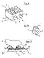
- Crimp contacts usable with paving stones crimping dies of the inventionare shown in Figures 2A and 2B. These contacts 10 are provided with pins 11 for crimping arranged in rings 12.
- the contacts representedinclude a termination of connection to a flexible circuit 40, this termination comprising a pallet 13 provided with spikes 11 arranged in a crown 12, the points being formed by a cross punching of the pallet then a stamping of the pallet folding the points and releasing a circular hole 14 forming the crown 12.
- the contacts shownalso include a termination 15 of connection with a contact complementary.
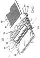
- a termination 15 of connection with a contact complementaryAs visible in figure 1 the contacts and the flexible circuit are received in an insulating housing 21 a connector module 20, the housing 21 being provided an open area 22 clearing the crimping area of the contacts on the flexible circuit above and below the crimping area.
- the pressureis applied by a segment of right of the pavement against the side edges of the points and leads to a flattening of the tip section and homogeneous deformation of the tip, the contact area widening along the descent of the pavement.
- the pinsbeing conical, the pressure generated by pins applies to point of contact between the spindle and the tip, this point of contact moving on the vertical central axis of the point, there not flattening of the petal but warping of the petal and not properly controlled deformation of the petal.
- FIG. 7Bshows that the petals obtained by applying the blocks 3 have been folded more regularly and have a more folded surface important than according to the prior art. Furthermore the base 142 of the petals is straight which facilitates the measurement the size and position of the petals by a computer-assisted camera measurement device.
- the tool consisting of the block forming the machined diemust be secured to a press 9.
- the block shownhas holes 5, 6 parallel to the two opposite surfaces facing bearing the pavers, the holes being arranged in a median plane at these two surfaces so that you can use both sides of the block.
- the blockcan include pawns or holding rails in the support, the main thing is that the block is precisely guided by the press during the crimping operation.
- the appropriate crimping device or station for crimping a connector 20 provided with a plurality of contactsincludes an anvil 50 forming a lower bearing surface for the elements of electrical contact 10. This anvil is more particularly visible in Figure 6B.
- the anvil 50is intended to be placed under the pallets 13 of contacts 10 when - the modules connector 20 are brought to the level of the crimping.
- This anvil as described in FIG. 6Bcomprises at at least one positioning element 51 and advantageously two positioning elements.
- the connectors as well as flexible circuitsare moved until the anvil 50 is under the pallets 13 of the contacts 10.
- the positioning elementsare then arranged opposite crowns of two contacts arranged at each end of the flexible circuit 40, each element positioning then being introduced into a hole circular of a crown either by vertical displacement of the anvil either by vertical displacement of the module.
- a holding device 126 of the connector module during crimpingis also provided, this device being mounted in parallel to the block on the press 9
- the positioning elementshave a piston device consisting of a tube 52 embedded in the anvil, this tube receiving a rod 53 mounted in the tube with a spring 54 allowing the sliding of the rod in the tube.
- the flexible circuit 40is then positioned on pallets 13 and the block is applied by the press on the flexible circuit, each of the blocks 3 strongly applying the flexible circuit 40 locally to the points 11 so as to pierce the flexible circuit and the tracks 41 then to arch the tips that come as well crimp the pallets on the flexible circuit and perform the electrical connection between contacts 10 and tracks conductors 41 of the flexible circuit.
- the operation of crimpingis visible schematically in Figure 4B.
- the rods 53 of the positioning devicedisappear towards the bottom under the action of the matrices.
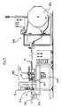
- FIG. 5An example of a complete automatic crimping station comprising a crimping station according to the invention is visible in Figure 5.
- This stationmay include a automated device for feeding 100 of these connectors with their pre-assembled contacts.
- Connectorscan be arranged and snapped onto a carrier strip 60 and supplied in rolls, a crimp station supply device then comprising a continuous unwinding station 121 of type known per se.
- the stationwill include, after the post unwinding, a device 100 for separating the connectors of the carrier strip and of the unit connectors to the crimping station.
- the connectorscan be fitted a window for clearing the crimping area and further provided with a circuit retention flap 28 flexible.
- the shuttermay include a frame connected by a hinge 23 to the connector housing receiving the contact.
- the frameallows the crimping operation to be carried out across flap 28, the flap being closed after the crimping operation, this flap 28 comprising a rear leg with one or more bosses 25 support and pressurization of the flexible circuit for isolate and protect the crimping area from possible stresses applied on the flexible circuit outside the connector.
- the installation of the pavers constituting the matrices of crimpingwill be carried out depending on the number of contacts by connector, pitch between contacts and number and arrangement of crimping crowns on the contacts.
- a device for which pavers will have a different section depending on the diameter of the crownsis of course possible as is the production of blocks for which the faces carrying the crimping dies have different configurations to allow to change matrices according to flexible circuit and connector configurations crimp.
Landscapes
- Engineering & Computer Science (AREA)
- Manufacturing & Machinery (AREA)
- Manufacturing Of Electrical Connectors (AREA)
- Coupling Device And Connection With Printed Circuit (AREA)
Abstract
Description
Translated fromFrenchL'invention concerne un outil et un dispositif desertissage de contacts sur circuits souples ainsi qu'unestation de sertissage notamment adaptés à l'assemblage etla réalisation de faisceaux munis de connecteurs surcircuits souples.The invention relates to a tool and a device forcrimping of contacts on flexible circuits as well as acrimping station particularly suitable for assembly andmaking beams with connectors onflexible circuits.
Les circuits souples sont des circuits électriquescomportant une feuille isolante sur laquelle sontdéposées des pistes conductrices, ces pistes étant ellesmêmes éventuellement recouverte d'une seconde feuilleisolante de protection.Flexible circuits are electrical circuitscomprising an insulating sheet on which aredeposited conductive tracks, these tracks being theysame possibly covered with a second sheetprotective insulation.
Le raccordement de tels circuits à des contactsélectriques se fait notamment par une technique depercement d'isolant et de sertissage et il est connud'utiliser pour ce faire des contacts munis d'uneterminaison de sertissage comportant des pointesdisposées en couronne et orientées perpendiculairement aucircuit souple à raccorder. Le document US 4 749 368décrit notamment la réalisation d'éléments de contact etde raccordement de composants munis de pointes deconnexion disposées en couronne.The connection of such circuits to contactselectric is done in particular by a technique ofinsulation piercing and crimping and it is knownto use for this purpose contacts provided with acrimp termination with spikesarranged in a crown and oriented perpendicular to theflexible circuit to be connected. US 4,749,368describes in particular the production of contact elements andfor connecting components fitted withconnection arranged in a crown.
Le sertissage des contacts sur le circuit souples'effectue traditionnellement en disposant les contactssous le circuit souple en regard des pistes conductricesdu circuit souple puis en sertissant les contacts sur lecircuit souple à l'aide de matrices de sertissagesformées en bout de broches cylindriques montées dans unbâti, un dispositif de presse venant appliquer lesbroches cylindriques sur le circuit souple du côté opposéaux couronnes, ce, au centre des couronnes, une surfaceformant enclume étant disposée sous les contacts pourappliquer une contre pression. Le résultat de l'opérationde sertissage est un percement de l'isolant par lespointes, les pointes étant ensuite rabattues en pétales.Crimping of contacts on the flexible circuitis traditionally done by arranging the contactsunder the flexible circuit opposite the conductive tracksof the flexible circuit then by crimping the contacts on theflexible circuit using crimping diesformed at the end of cylindrical pins mounted in aframe, a press device applying thecylindrical pins on the flexible circuit on the opposite sideto the crowns, this, in the center of the crowns, a surfaceforming an anvil being disposed under the contacts forapply back pressure. The result of the operationis a piercing of the insulation by thepoints, the points then being folded down into petals.
Le principe utilisant de telles broches est par exempledécrit dans le document "SAE technical paper series870553 Flex foil crimp technology - InternationalCongress and Exposition Detroit Michigan 23 - 27 février1987.The principle using such pins is for exampledescribed in the document "SAE technical paper series870553 Flex foil crimp technology - InternationalCongress and Exposition Detroit Michigan February 23 - 271987.
Le diamètre des couronnes est de l'ordre du millimètrepour des circuits et des contacts destines à véhiculerdes courants de l'ordre de quelques Ampères.The diameter of the crowns is of the order of a millimeterfor circuits and contacts intended to conveycurrents on the order of a few Amps.
Pour des circuits souples à grand nombre de pistes avecpar exemple un pas entre pistes de 1 à 5 mm il estnécessaire de réaliser un grand nombre de broches deprécision montées dans un bâti lui même pourvu de trous de réception des broches usinées avec une grandeprécision, les broches devant par ailleurs au niveau deleurs terminaisons de sertissage présenter unecoplanaréité très stricte.For flexible circuits with a large number of tracks withfor example a pitch between tracks of 1 to 5 mm it isnecessary to make a large number of pinsprecision mounted in a frame itself provided with holesreceiving spindles machined with a largeprecision, the pins also in front oftheir crimp terminations present avery strict co-planarity.
Une telle réalisation est coûteuse et, même si lesbroches ont une durée de vie importante de l'ordre de 800000 sertissages, des risques de rupture existent etl'opération de remplacement d'une broche est complexe,les broches étant chacune maintenue dans le bâti par destiges montées perpendiculairement aux broches dans lebâti.Such an implementation is expensive and, even if thepins have a long service life of around 800000 crimps, risks of rupture exist andthe operation of replacing a spindle is complex,the pins each being held in the frame byrods mounted perpendicular to the pins in theframe.
Par ailleurs, lors du sertissage, il se peut que lesbroches viennent frapper selon un axe différent de l'axeperpendiculaire passant par le centre de la couronne.Dans ce cas, l'empreinte de sertissage présentera desirrégularités dans la forme des pétales et dans un casparticulièrement défavorable une pointe pourra ne pasêtre repliée ou rester prisonnière dans l'isolant ceconduisant ainsi à une dégradation des caractéristiquesélectriques et mécaniques du sertissage.In addition, during crimping, it may be that thepins strike along an axis different from the axisperpendicular through the center of the crown.In this case, the crimping impression will showirregularities in the shape of the petals and in one caseparticularly unfavorable a tip may notbe folded back or remain trapped in the insulationthus leading to a degradation of the characteristicselectrical and mechanical crimping.
La présente invention propose notamment une structure dematrices de sertissage simplifiée et peu onéreuse quipermet de contrôleur très précisément le pas entre lesmatrices de sertissage, la coplanaréité des matrices etde minimiser les défauts obtenus lors du sertissage en réalisant une déformation contrôlée simultanée de toutesles pointes.The present invention notably provides a structure forsimplified and inexpensive crimping dies whichallows to control very precisely the pitch betweencrimping dies, coplanarity of dies andto minimize the defects obtained during crimping byachieving simultaneous controlled deformation of allpeaks.
Dans ce but et selon un premier aspect, l'invention estbasée principalement sur la réalisation d'un outil desertissage de palettes de contacts électriques sur despistes conductrices d'un circuit souple, cet outilcomportant un réseau multipoints de matrices desertissage constitué à partir d'un bloc massif comportantau moins une surface plane sur laquelle un réseau depavés de section polygonale et à base évasée est usiné,les pavés constituant les matrices.For this purpose and according to a first aspect, the invention isbased mainly on the creation of acrimping of electrical contact pallets onconductive tracks of a flexible circuit, this toolcomprising a multi-point network of matrices ofcrimping made from a solid block comprisingat least one flat surface on which a network ofpavers of polygonal section and with flared base is machined,the blocks making up the matrices.
Les pavés peuvent notamment avoir un profil formant surchacune de leurs faces latérales une courbe s'évasant dela section terminale du pavé vers la base du pavé zone deliaison du pavé et du bloc.The pavers may in particular have a profile forming oneach of their lateral faces a curve widening bythe terminal section of the paver towards the base of the area paverconnection of the block and the block.
De manière avantageuse le bloc constituant la matricemultipoints peut comporter un réseau de pavés sur chacunedes deux surfaces.Advantageously the block constituting the matrixmultipoint can have a network of pavers on eachof the two surfaces.
En mode de réalisation particulier adapté à des contactsmunis de pointes de sertissage disposées en couronne, lasection terminale polygonale des pavés est orientée detelle sorte que les faces latérales des pavés viennent encontact avec les pointes de sertissage lors de l'opération de sertissage de façon à repousser lespointes et de les conformer en pétales.In a particular embodiment suitable for contactsfitted with crimping pins arranged in a crown, thepolygonal end section of the pavers is oriented fromso that the side faces of the pavers come incontact with the crimping points duringthe crimping operation so as to repel thetips and conform them into petals.
L'invention concerne en outre un dispositif de sertissagesimultané sur un circuit souple d'éléments de contactélectriques alignés dans un plan.The invention further relates to a crimping devicesimultaneous on a flexible circuit of contact elementselectric aligned in a plane.
Ce dispositif est adapté pour le sertissage d'unconnecteur muni d'une pluralité de contacts. Dans ce typede connecteur les contacts comportent d'une part uneterminaison de raccordement à un circuit souple, cetteterminaison comportant une palette munies de pointesdisposées en couronne, les pointes étant constituées parun poinçonnage en croix de la palette puis unemboutissage de la palette repliant les pointes etdégageant un trou circulaire formant la couronne.This device is suitable for crimping aconnector provided with a plurality of contacts. In this typeof connector the contacts comprise on the one hand atermination of connection to a flexible circuit, thistermination including a pallet with spikesarranged in a crown, the points being constituted bya cross punching of the pallet then astamping of the pallet folding the points andreleasing a circular hole forming the crown.
Les contacts comportent d'autre part une terminaison deconnexion avec un contact complémentaires, les contactset le circuit souple étant reçus dans un boítier isolantmuni d'une zone ouverte dégageant la zone de sertissagedes contacts sur le circuit souple au dessus et audessous de la zone de sertissage.The contacts also include a termination ofconnection with a complementary contact, the contactsand the flexible circuit being received in an insulating housingprovided with an open area clearing the crimping areacontacts on the flexible circuit above and atbelow the crimping area.
Pour sertir les contacts le dispositif comporte d'unepart une enclume formant une surface d'appui inférieurepour les éléments de contact électriques, le dispositifde sertissage comportant d'autre part un dispositif mobile de presse muni d'un bloc dont la surface parallèleau plan d'alignement des contacts comporte une pluralitéde matrices de sertissage constituées par des pavés àsection terminale polygonale.To crimp the contacts, the device has ashare an anvil forming a lower bearing surfacefor electrical contact elements, the devicecrimping device further comprising a devicepress mobile fitted with a block whose parallel surfaceat the contact alignment plane has a pluralityof crimping dies constituted by blocks withpolygonal end section.
L'enclume disposée sous les palettes peut comporter aumoins un élément de positionnement et avantageusementdeux éléments de positionnement disposés en regard decouronnes de deux contacts disposés à chaque extrémité ducircuit souple, chaque élément de positionnement étantintroduit dans l'un des trous circulaires des couronnes.The anvil placed under the pallets may includeless a positioning element and advantageouslytwo positioning elements arranged oppositecrowns of two contacts arranged at each end of theflexible circuit, each positioning element beinginserted into one of the circular holes in the crowns.
Le circuit souple est alors positionné sur les paletteset le bloc appliqué par la presse sur le circuit souple,chacune des matrices appliquant fortement localement lecircuit souple sur les pointes de façon à percer lecircuit souple puis à cambrer les pointes qui viennentainsi sertir les palettes sur le circuit souple eteffectuer la liaison électrique entre les contacts et lespistes du circuit souple.The flexible circuit is then positioned on the palletsand the block applied by the press on the flexible circuit,each of the matrices applying strongly locally theflexible circuit on the tips so as to pierce theflexible circuit then to arch the points which comethus crimp the pallets on the flexible circuit andmake the electrical connection between the contacts and theflexible circuit tracks.
L'ensemble enclume et presse munie du bloc de sertissageselon l'invention constitue ainsi un dispositif desertissage optimisé permettant un sertissage de précisionavec une grande reproductibilité des sertissages etréalisant une empreinte de sertissage apte à êtrecontrôlée par un dispositif caméra avec un taux d'erreurminimisé.The anvil and press assembly fitted with the crimping blockaccording to the invention thus constitutes a device forOptimized crimping for precision crimpingwith high reproducibility of crimps andproducing a crimping imprint capable of beingcontrolled by a camera device with an error rateminimized.
L'implantation des pavés constituant les matrices desertissage sera réalisée en fonction du nombre decontacts par connecteur et du nombre et de la dispositiondes couronnes de sertissage. Un dispositif pour lequelles pavés auront une section polygonale différente enfonction du diamètre des couronnes est bien entendupossible.The installation of the pavers constituting the matrices ofcrimping will be carried out depending on the number ofcontacts per connector and the number and arrangementcrimping crowns. A device for whichthe paving stones will have a different polygonal section infunction of the crown diameter is of coursepossible.
D'autres aspects et avantages de l'invention seront mieuxcomprise à la lecture de la description qui va suivred'un mode de réalisation non limitatif en référence auxdessins qui représentent:
En référence à la figure 3 un outil de sertissageconforme à un premier aspect de l'invention estreprésenté. Cet outil est basé principalement sur laréalisation d'un réseau multipoints de matrices desertissage constitué à partir d'un bloc massif 1.Referring to Figure 3 a crimping toolaccording to a first aspect of the invention isrepresented. This tool is mainly based on thecreation of a multi-point network of matrices ofcrimping made from a solid block 1.
Ce réseau peut être réalisé par un procédé d'électro-érosionafin d'obtenir une grande précision et un état desurface très lisse.This network can be produced by an electro-erosion processin order to obtain high accuracy and a state ofvery smooth surface.
Le réseau est réalisé sur une surface plane 2 du bloc etle réseau de matrices comporte un réseau de pavés 3 desection polygonale et à base évasée, les pavésconstituant les matrices.The network is made on a
Afin de courber les pointes de sertissages visibles enfigure 4A les pavés ont un profil formant sur chacune deleurs faces latérales une courbe s'évasant de la sectionterminale du pavé vers l'emplanture du pavé. Les faceslatérales sont appliquées contre les pointes et lesforcent à se conformer en pétales.In order to bend the visible crimp tips inFigure 4A the pavers have a profile forming on each oftheir side faces a curve widening from the sectionterminal of the paver towards the root of the paver. The facesside are applied against the tips andforce to comply in petals.
Le bloc constituant la matrice multipoints peut comporterun réseau de pavés sur deux surfaces 2, 4 parallèlesopposées du bloc. Ceci permet lorsqu'un premier réseau dematrices est usé, de minimiser les temps d'immobilisationde la machine en retournant le bloc.The block constituting the multipoint matrix can comprisea network of pavers on two
Des contacts à sertir utilisables avec les pavés dematrices de sertissage de l'invention sont représentés enfigures 2A et 2B. Ces contacts 10 sont munis de pointes11 de sertissage disposées en couronnes 12.Crimp contacts usable with paving stonescrimping dies of the invention are shown inFigures 2A and 2B. These
Les contacts représentés comportent d'une part uneterminaison de raccordement à un circuit souple 40, cetteterminaison comportant une palette 13 munie de pointes 11disposées en couronne 12, les pointes étant constituéespar un poinçonnage en croix de la palette puis unemboutissage de la palette repliant les pointes etdégageant un trou circulaire 14 formant la couronne 12.On the one hand, the contacts represented include atermination of connection to a
Les contacts représentés comportent d'autre part uneterminaison 15 de connexion avec un contactcomplémentaire. Comme visible en figure 1 les contacts etle circuit souple sont reçus dans un boítier isolant 21d'un module de connecteur 20, le boítier 21 étant munid'une zone ouverte 22 dégageant la zone de sertissage descontacts sur le circuit souple au dessus et au dessous dela zone de sertissage.The contacts shown also include a
Afin de sertir l'ensemble des contacts en position dansle module de connecteur 20 la section terminalepolygonale des pavés est orientée de telle sorte que lesfaces latérales des pavés viennent en contact avec lespointes de sertissage lors de l'opération de sertissagede façon à repousser les pointes et de les conformer enpétales 141, les empreintes des matrices 201, 202, 203,204 visibles sur le circuit souple en figure 7B sont desection carrée à la différence des empreintes 211, 212,213, 214 circulaires résultant de l'application desbroches de l'art antérieur visibles en figure 7A. Lacomparaison des figures 7A et 7B montre le résultat del'application des faces des pavés contre les pointes.In order to crimp all the contacts in position in
Du fait que les pavés appuient par leurs faces contre lespointes, la pression est appliquée par un segment dedroite du pavé contre les arêtes latérales des pointes etconduit à un aplatissement de la section des pointes etune déformation homogène de la pointe, la zone de contact s'élargissant au long de la descente du pavé. Dans l'artantérieur les broches étant de type conique, la pressiongénérée par les broches s'applique au point de contactentre la broche et la pointe, ce point de contact sedéplaçant sur l'axe central vertical de la pointe, il n'ya pas aplatissement du pétale mais gauchissement dupétale et déformation non correctement contrôlée dupétale. Il est visible en figure 7B que les pétalesobtenus par l'application des pavés 3 ont été repliésplus régulièrement et ont une surface repliée plusimportante que selon la technique antérieure. De plus labase 142 des pétales est droite ce qui facilite la mesurede la dimension et de la position des pétales par undispositif de mesure par caméra assisté par ordinateur.Because the pavers press by their faces against thepoints, the pressure is applied by a segment ofright of the pavement against the side edges of the points andleads to a flattening of the tip section andhomogeneous deformation of the tip, the contact areawidening along the descent of the pavement. In artanterior, the pins being conical, the pressuregenerated by pins applies to point of contactbetween the spindle and the tip, this point of contactmoving on the vertical central axis of the point, therenot flattening of the petal but warping of thepetal and not properly controlled deformation of thepetal. It is visible in FIG. 7B that the petalsobtained by applying the
Pour constituer le dispositif de sertissage et commevisible en figure 5 l'outil constitué du bloc formant lamatrice usinée doit être solidarisé à une presse 9. Pourcela le bloc représenté comporte des trous 5, 6parallèles aux deux surfaces opposées en regard portantles pavés, les trous étant disposés dans un plan médian àces deux surfaces de façon à pouvoir utiliser les deuxcôtés du bloc.To constitute the crimping device and asvisible in Figure 5 the tool consisting of the block forming themachined die must be secured to a press 9. Tothat the block shown has
Ces trous reçoivent des tiges 7, 8 de maintien et deguidage du bloc pour solidariser le bloc avec un supportlui même solidaire du piston de la presse de sertissage9.These holes receive
Pour sa fixation le bloc peut comporter des pions ou desrails de maintien dans le support, l'essentiel étant quele bloc soit précisément guidé par la presse lors del'opération de sertissage.For its fixing the block can include pawns orholding rails in the support, the main thing is thatthe block is precisely guided by the press duringthe crimping operation.
En plus d'un dispositif mobile de presse 9 muni d'un bloc1 dont la surface parallèle au plan d'alignement descontacts comporte une pluralité de matrices de sertissageconstituées par des pavés 3 à section terminalepolygonale, le dispositif ou poste de sertissage adaptépour le sertissage d'un connecteur 20 muni d'unepluralité de contacts 10, comporte une enclume 50 formantune surface d'appui inférieure pour les éléments decontact électriques 10. Cette enclume est plusparticulièrement visible en figure 6B.In addition to a mobile press device 9 provided with a block1 whose surface parallel to the alignment plane of thecontacts comprises a plurality of crimping diesconstituted by
L'enclume 50 est destinée à être disposée sous lespalettes 13 des contacts 10 lorsque - les modules deconnecteur 20 sont amenés au niveau du poste desertissage.The
Cette enclume telle que décrite en figure 6B comporte aumoins un élément de positionnement 51 et avantageusementdeux éléments de positionnement.This anvil as described in FIG. 6B comprises atat least one
Pour l'opération de sertissage, les modules deconnecteurs ainsi que les circuits souples sont déplacés jusqu'à ce que l'enclume 50 soit sous les palettes 13 descontacts 10. Les éléments de positionnement sont alorsdisposés en regard de couronnes de deux contacts disposésà chaque extrémité du circuit souple 40, chaque élémentde positionnement étant alors introduit dans un troucirculaire d'une couronne soit par déplacement verticalde l'enclume soit par déplacement vertical du module.For the crimping operation, theconnectors as well as flexible circuits are moveduntil the
Comme visible en figure 5, un dispositif de maintien 126du module de connecteur pendant le sertissage est aussiprévu, ce dispositif étant monté en parallèle au bloc surla presse 9As can be seen in FIG. 5, a holding
Selon la figure 6B les éléments de positionnementcomportent un dispositif piston constitué d'un tube 52encastré dans l'enclume, ce tube recevant une tige 53montée dans le tube avec un ressort 54 permettant lecoulissement de la tige dans le tube.According to FIG. 6B, the positioning elementshave a piston device consisting of a tube 52embedded in the anvil, this tube receiving a rod 53mounted in the tube with a spring 54 allowing thesliding of the rod in the tube.
Comme décrit en figure 6A le circuit souple 40 est alorspositionné sur les palettes 13 et le bloc est appliquépar la presse sur le circuit souple, chacun des pavés 3appliquant fortement localement le circuit souple 40 surles pointes 11 de façon à percer le circuit souple et lespistes 41 puis à cambrer les pointes qui viennent ainsisertir les palettes sur le circuit souple et effectuer laliaison électrique entre les contacts 10 et les pistes conductrices 41 du circuit souple. L'opération desertissage est visible schématiquement en figure 4B.As described in FIG. 6A, the
Lors de l'application des pavés formant matrices sur lecircuit souple puis sur les pointes de la couronne, lestiges 53 du dispositif de positionnement s'effacent versle bas sous l'action des matrices.When applying the matrix pavers on theflexible circuit then on the tips of the crown, therods 53 of the positioning device disappear towardsthe bottom under the action of the matrices.
Un exemple de station de sertissage automatique complètecomportant un poste de sertissage conforme à l'inventionest visible en figure 5. Cette station peut comporter undispositif automatisé d'amenée 100 de ces connecteursavec leurs contacts pré-montés.An example of a complete automatic crimping stationcomprising a crimping station according to the inventionis visible in Figure 5. This station may include aautomated device for feeding 100 of these connectorswith their pre-assembled contacts.
Les connecteurs peuvent être disposés et encliquetés surune bande porteuse 60 et fournis en rouleaux, undispositif d'alimentation de la station de sertissagecomportant alors un poste de déroulage en continu 121 detype connu en soi.Connectors can be arranged and snapped ontoa
Dans le cas où les connecteurs sont disposés sur unebande porteuse 60 la station comportera, après le postede déroulage, un dispositif 100 de désolidarisation desconnecteurs de la bande porteuse et d'amenée desconnecteurs unitaires vers le poste de sertissage.In the case where the connectors are arranged on a
Visible en figure 1, les connecteurs peuvent être munisd'une fenêtre de dégagement de la zone de sertissage et munis en outre d'un volet 28 de rétention du circuitsouple. Le volet peut comporter un cadre relié par unecharnière 23 au boítier de connecteur recevant lescontacts.Visible in Figure 1, the connectors can be fitteda window for clearing the crimping area andfurther provided with a
Le cadre permet d'effectuer l'opération de sertissage autravers du volet 28, le volet étant refermé aprèsl'opération de sertissage, ce volet 28 comportant unebranche arrière munie d'un ou plusieurs bossages 25d'appui et de mise en pression du circuit souple pourisoler et protéger la zone de sertissage d'éventuellescontraintes appliquées sur le circuit souple en dehors duconnecteur.The frame allows the crimping operation to be carried outacross
L'implantation des pavés constituant les matrices desertissage sera réalisée en fonction du nombre decontacts par connecteur, du pas entre les contacts et dunombre et de la disposition des couronnes de sertissagesur les contacts. Un dispositif pour lequel les pavésauront une section différente en fonction du diamètre descouronnes est bien entendu possible de même que laréalisation de blocs pour lesquels les faces portant lesmatrices de sertissage ont des configurations différentespour permettre de changer de matrices selon lesconfigurations de circuits souples et de connecteurs àsertir.The installation of the pavers constituting the matrices ofcrimping will be carried out depending on the number ofcontacts by connector, pitch between contacts andnumber and arrangement of crimping crownson the contacts. A device for which paverswill have a different section depending on the diameter of thecrowns is of course possible as is theproduction of blocks for which the faces carrying thecrimping dies have different configurationsto allow to change matrices according toflexible circuit and connector configurationscrimp.
Claims (11)
Translated fromFrenchApplications Claiming Priority (2)
| Application Number | Priority Date | Filing Date | Title |
|---|---|---|---|
| FR0101184 | 2001-01-23 | ||
| FR0101184AFR2819945A1 (en) | 2001-01-23 | 2001-01-23 | TOOL AND CRIMPING DEVICE FOR FLEXIBLE CIRCUIT AND CRIMPING STATION PROVIDED WITH SUCH A DEVICE |
Publications (2)
| Publication Number | Publication Date |
|---|---|
| EP1225658A1true EP1225658A1 (en) | 2002-07-24 |
| EP1225658B1 EP1225658B1 (en) | 2007-07-18 |
Family
ID=8859362
Family Applications (1)
| Application Number | Title | Priority Date | Filing Date |
|---|---|---|---|
| EP02001086AExpired - LifetimeEP1225658B1 (en) | 2001-01-23 | 2002-01-22 | Crimping tool and device for flexible circuits and crimping station having such a device |
Country Status (7)
| Country | Link |
|---|---|
| US (1) | US6718815B2 (en) |
| EP (1) | EP1225658B1 (en) |
| AT (1) | ATE367663T1 (en) |
| DE (1) | DE60221167T2 (en) |
| ES (1) | ES2289017T3 (en) |
| FR (1) | FR2819945A1 (en) |
| IT (1) | ITTO20010406A1 (en) |
Cited By (1)
| Publication number | Priority date | Publication date | Assignee | Title |
|---|---|---|---|---|
| DE202004005803U1 (en)* | 2004-04-08 | 2005-09-29 | Schleuniger Holding Ag | Contact device for simultaneous electrical connection of foil conductor contacts, uses swivel movement to move upper tool towards lower tool via drive device |
Families Citing this family (9)
| Publication number | Priority date | Publication date | Assignee | Title |
|---|---|---|---|---|
| ITTO20010367A1 (en)* | 2001-04-13 | 2002-10-13 | Framatome Connectors Int | METHOD AND CRIMPING UNIT TO JOIN AN ELECTRIC CONNECTOR TO A FLAT ELECTRIC CABLE. |
| ITTO20010366A1 (en)* | 2001-04-13 | 2002-10-13 | Framatome Connectors Int | UNIT FOR SEWING ELECTRIC TERMINALS ON RESPECTIVE CONDUCTIVE SLOPES OF A FLAT CABLE. |
| GB2401334A (en)* | 2003-05-09 | 2004-11-10 | David Tien | Pressing device for thin-film circuit and terminal |
| US7332048B2 (en)* | 2004-11-17 | 2008-02-19 | The Boeing Company | Forming and bonding of flex circuits to structures |
| US7443354B2 (en)* | 2005-08-09 | 2008-10-28 | The Boeing Company | Compliant, internally cooled antenna apparatus and method |
| US7410384B2 (en)* | 2006-05-16 | 2008-08-12 | Fci Americas Technology, Inc. | Electrical contact with stapled connection |
| CN101437360B (en)* | 2007-11-12 | 2011-12-21 | 富葵精密组件(深圳)有限公司 | Flexible circuit board, preparation method and fixed method thereof |
| US8503941B2 (en) | 2008-02-21 | 2013-08-06 | The Boeing Company | System and method for optimized unmanned vehicle communication using telemetry |
| US9799965B2 (en) | 2014-05-17 | 2017-10-24 | Igor Ofenbakh | System for coupling a conductive substrate to a ribbon cable |
Citations (3)
| Publication number | Priority date | Publication date | Assignee | Title |
|---|---|---|---|---|
| US3924917A (en)* | 1974-04-30 | 1975-12-09 | Elco Corp | Flat cable termination method and apparatus |
| US4543716A (en)* | 1983-09-23 | 1985-10-01 | The Wiremold Company | Method and apparatus for electrical connection of flat cables |
| EP0243998A1 (en)* | 1986-04-03 | 1987-11-04 | E.I. Du Pont De Nemours And Company | Contact strip |
Family Cites Families (14)
| Publication number | Priority date | Publication date | Assignee | Title |
|---|---|---|---|---|
| US1677968A (en)* | 1923-01-08 | 1928-07-24 | United Shoe Machinery Corp | Fastener-applying device |
| US2064322A (en)* | 1933-10-11 | 1936-12-15 | Western Electric Co | Method of surface finishing articles |
| US3190953A (en)* | 1961-06-15 | 1965-06-22 | Martin Marietta Corp | Channel flanged capillary eyelet for printed circuit boards |
| US3299493A (en)* | 1964-06-25 | 1967-01-24 | Methode Electronics Inc | Method of making forked contacts |
| US3526955A (en)* | 1968-03-26 | 1970-09-08 | Us Industries Inc | Method of attaching fastener components |
| US3840840A (en)* | 1973-08-10 | 1974-10-08 | Continental Wirt Electronic | Flat conductor cable connector |
| US4066319A (en)* | 1974-04-30 | 1978-01-03 | Elco Corporation | Method and apparatus for flat conductor cable termination |
| US4027521A (en)* | 1975-01-30 | 1977-06-07 | Trw Inc. | Apparatus for making terminal connectors |
| US4414740A (en)* | 1979-05-25 | 1983-11-15 | Allied Corporation | Insulation-pierce and crimp termination tool |
| US4831722A (en)* | 1981-10-26 | 1989-05-23 | Burndy Corporation | Apparatus and method for installing electrical connectors on flat conductor cable |
| US4798070A (en)* | 1983-07-01 | 1989-01-17 | Colt Industries Operating Corporation | Combined thread rolling dies |
| JPS6031092U (en)* | 1983-08-09 | 1985-03-02 | シ−ケ−デイ株式会社 | terminal crimping machine |
| US5161403A (en)* | 1991-06-25 | 1992-11-10 | Digital Equipment Corporation | Method and apparatus for forming coplanar contact projections on flexible circuits |
| JP3738959B2 (en)* | 2000-07-27 | 2006-01-25 | 矢崎総業株式会社 | Terminal caulking method and apparatus |
- 2001
- 2001-01-23FRFR0101184Apatent/FR2819945A1/enactivePending
- 2001-04-27ITIT2001TO000406Apatent/ITTO20010406A1/enunknown
- 2002
- 2002-01-22DEDE60221167Tpatent/DE60221167T2/ennot_activeExpired - Lifetime
- 2002-01-22ATAT02001086Tpatent/ATE367663T1/ennot_activeIP Right Cessation
- 2002-01-22EPEP02001086Apatent/EP1225658B1/ennot_activeExpired - Lifetime
- 2002-01-22ESES02001086Tpatent/ES2289017T3/ennot_activeExpired - Lifetime
- 2002-01-23USUS10/056,620patent/US6718815B2/ennot_activeExpired - Fee Related
Patent Citations (4)
| Publication number | Priority date | Publication date | Assignee | Title |
|---|---|---|---|---|
| US3924917A (en)* | 1974-04-30 | 1975-12-09 | Elco Corp | Flat cable termination method and apparatus |
| US4543716A (en)* | 1983-09-23 | 1985-10-01 | The Wiremold Company | Method and apparatus for electrical connection of flat cables |
| EP0243998A1 (en)* | 1986-04-03 | 1987-11-04 | E.I. Du Pont De Nemours And Company | Contact strip |
| US4749368A (en)* | 1986-04-03 | 1988-06-07 | E. I. Du Pont De Nemours And Company | Contact strip terminal |
Cited By (1)
| Publication number | Priority date | Publication date | Assignee | Title |
|---|---|---|---|---|
| DE202004005803U1 (en)* | 2004-04-08 | 2005-09-29 | Schleuniger Holding Ag | Contact device for simultaneous electrical connection of foil conductor contacts, uses swivel movement to move upper tool towards lower tool via drive device |
Also Published As
| Publication number | Publication date |
|---|---|
| FR2819945A1 (en) | 2002-07-26 |
| ES2289017T3 (en) | 2008-02-01 |
| ITTO20010406A0 (en) | 2001-04-27 |
| ATE367663T1 (en) | 2007-08-15 |
| DE60221167D1 (en) | 2007-08-30 |
| ITTO20010406A1 (en) | 2002-10-27 |
| DE60221167T2 (en) | 2008-03-20 |
| US6718815B2 (en) | 2004-04-13 |
| EP1225658B1 (en) | 2007-07-18 |
| US20020124625A1 (en) | 2002-09-12 |
Similar Documents
| Publication | Publication Date | Title |
|---|---|---|
| EP1225658B1 (en) | Crimping tool and device for flexible circuits and crimping station having such a device | |
| EP0121467A1 (en) | Microconnector with a high contact density | |
| EP0108700A1 (en) | Dobby with selection of the hooks | |
| EP0219408B1 (en) | Process and device for welding elements on the corresponding spots of a substrate, such as a high-density integrated-circuit substrate | |
| EP0463693A2 (en) | Apparatus and system for punching printed circuit boards | |
| FR2530507A1 (en) | SIMPLIFIED CONSTRUCTION OF TOOLS FOR EXTENDING THE USE OF TOOLS TO THE BAND IN THE SMALL AND MEDIUM-SIZED MANUFACTURE OF METALLIC ARTICLES | |
| EP0161961B1 (en) | Connector, process for inserting a male contact into a female contact and apparatus for carrying out the process | |
| WO1992002059A1 (en) | Methods and devices for mechanically crimping a connection part on a wire | |
| EP0123574A1 (en) | Apparatus for automatically affixing electrical conductors on a regrouping part | |
| FR2819791A1 (en) | CONNECTOR MODULES SUITABLE FOR BANDING THEM | |
| EP1225661B1 (en) | Device for feeding connectors and crimping station comprising such device | |
| EP3820265B1 (en) | Method and device for cutting a radial electronic component | |
| EP0309359B1 (en) | Method for automatically controlling the self-inductance of wound elements comprising a magnetic circuit with an adjustable air gap | |
| CH675932A5 (en) | ||
| EP1162013B1 (en) | Workpiece transfer device for a stamping and/or cutting press | |
| FR2531569A1 (en) | Circuit-breaker and method for the continuous manufacture of the same | |
| FR2884362A1 (en) | FLAT CIRCUIT BODY WITH TERMINALS, MANUFACTURING METHOD THEREOF, MATRIX SYSTEM FOR MANUFACTURING THE SAME, AND APPARATUS FOR MANUFACTURING THE SAME | |
| FR2524726A1 (en) | Variable tool crimping machine for electric terminal lugs - has rotatable anvil and crimping heads which can be selected for different-sized lugs and wires | |
| EP1105949A1 (en) | Device for crimping a series of metal lugs and pre-adjusted cartridge for guiding a set of lugs | |
| EP0274503A1 (en) | FEMALE CONTACT ELEMENT, BELT COMPRISING SAME AND MANUFACTURING METHOD THEREOF. | |
| FR2466173A1 (en) | Tool for separating conductors on substrate - has capacitor which is discharged via two electrodes to melt conductor | |
| FR2497414A1 (en) | Press for crimping terminals on electrical wires - has guiding passage of which width is easily adjustable to terminal widths by cam mechanism | |
| EP2781693A1 (en) | Conductive element for manufacturing a heating system | |
| EP1014517A1 (en) | Method and device to take a connector apart from a printed circuit board | |
| FR2496329A1 (en) | MULTIMETALLIC CONTACT AND METHOD OF MAKING |
Legal Events
| Date | Code | Title | Description |
|---|---|---|---|
| PUAI | Public reference made under article 153(3) epc to a published international application that has entered the european phase | Free format text:ORIGINAL CODE: 0009012 | |
| AK | Designated contracting states | Kind code of ref document:A1 Designated state(s):AT BE CH CY DE DK ES FI FR GB GR IE IT LI LU MC NL PT SE TR | |
| AX | Request for extension of the european patent | Free format text:AL;LT;LV;MK;RO;SI | |
| 17P | Request for examination filed | Effective date:20030113 | |
| AKX | Designation fees paid | Designated state(s):AT BE CH CY DE DK ES FI FR GB GR IE IT LI LU MC NL PT SE TR | |
| GRAP | Despatch of communication of intention to grant a patent | Free format text:ORIGINAL CODE: EPIDOSNIGR1 | |
| RIN1 | Information on inventor provided before grant (corrected) | Inventor name:FANTINI, FLAVIO M. | |
| GRAS | Grant fee paid | Free format text:ORIGINAL CODE: EPIDOSNIGR3 | |
| GRAA | (expected) grant | Free format text:ORIGINAL CODE: 0009210 | |
| AK | Designated contracting states | Kind code of ref document:B1 Designated state(s):AT BE CH CY DE DK ES FI FR GB GR IE IT LI LU MC NL PT SE TR | |
| REG | Reference to a national code | Ref country code:GB Ref legal event code:FG4D Free format text:NOT ENGLISH | |
| RAP2 | Party data changed (patent owner data changed or rights of a patent transferred) | Owner name:FCI | |
| REG | Reference to a national code | Ref country code:CH Ref legal event code:EP | |
| REF | Corresponds to: | Ref document number:60221167 Country of ref document:DE Date of ref document:20070830 Kind code of ref document:P | |
| NLT2 | Nl: modifications (of names), taken from the european patent patent bulletin | Owner name:FCI Effective date:20070725 | |
| REG | Reference to a national code | Ref country code:IE Ref legal event code:FG4D Free format text:LANGUAGE OF EP DOCUMENT: FRENCH | |
| PG25 | Lapsed in a contracting state [announced via postgrant information from national office to epo] | Ref country code:NL Free format text:LAPSE BECAUSE OF FAILURE TO SUBMIT A TRANSLATION OF THE DESCRIPTION OR TO PAY THE FEE WITHIN THE PRESCRIBED TIME-LIMIT Effective date:20070718 Ref country code:PT Free format text:LAPSE BECAUSE OF FAILURE TO SUBMIT A TRANSLATION OF THE DESCRIPTION OR TO PAY THE FEE WITHIN THE PRESCRIBED TIME-LIMIT Effective date:20071218 Ref country code:FI Free format text:LAPSE BECAUSE OF FAILURE TO SUBMIT A TRANSLATION OF THE DESCRIPTION OR TO PAY THE FEE WITHIN THE PRESCRIBED TIME-LIMIT Effective date:20070718 | |
| NLV1 | Nl: lapsed or annulled due to failure to fulfill the requirements of art. 29p and 29m of the patents act | ||
| REG | Reference to a national code | Ref country code:ES Ref legal event code:FG2A Ref document number:2289017 Country of ref document:ES Kind code of ref document:T3 | |
| GBV | Gb: ep patent (uk) treated as always having been void in accordance with gb section 77(7)/1977 [no translation filed] | Effective date:20070718 | |
| PG25 | Lapsed in a contracting state [announced via postgrant information from national office to epo] | Ref country code:AT Free format text:LAPSE BECAUSE OF FAILURE TO SUBMIT A TRANSLATION OF THE DESCRIPTION OR TO PAY THE FEE WITHIN THE PRESCRIBED TIME-LIMIT Effective date:20070718 | |
| REG | Reference to a national code | Ref country code:IE Ref legal event code:FD4D | |
| PG25 | Lapsed in a contracting state [announced via postgrant information from national office to epo] | Ref country code:GR Free format text:LAPSE BECAUSE OF FAILURE TO SUBMIT A TRANSLATION OF THE DESCRIPTION OR TO PAY THE FEE WITHIN THE PRESCRIBED TIME-LIMIT Effective date:20071019 Ref country code:DK Free format text:LAPSE BECAUSE OF FAILURE TO SUBMIT A TRANSLATION OF THE DESCRIPTION OR TO PAY THE FEE WITHIN THE PRESCRIBED TIME-LIMIT Effective date:20070718 | |
| PLBE | No opposition filed within time limit | Free format text:ORIGINAL CODE: 0009261 | |
| STAA | Information on the status of an ep patent application or granted ep patent | Free format text:STATUS: NO OPPOSITION FILED WITHIN TIME LIMIT | |
| PG25 | Lapsed in a contracting state [announced via postgrant information from national office to epo] | Ref country code:GB Free format text:LAPSE BECAUSE OF FAILURE TO SUBMIT A TRANSLATION OF THE DESCRIPTION OR TO PAY THE FEE WITHIN THE PRESCRIBED TIME-LIMIT Effective date:20070718 Ref country code:IE Free format text:LAPSE BECAUSE OF FAILURE TO SUBMIT A TRANSLATION OF THE DESCRIPTION OR TO PAY THE FEE WITHIN THE PRESCRIBED TIME-LIMIT Effective date:20070718 | |
| 26N | No opposition filed | Effective date:20080421 | |
| PG25 | Lapsed in a contracting state [announced via postgrant information from national office to epo] | Ref country code:SE Free format text:LAPSE BECAUSE OF FAILURE TO SUBMIT A TRANSLATION OF THE DESCRIPTION OR TO PAY THE FEE WITHIN THE PRESCRIBED TIME-LIMIT Effective date:20071018 | |
| BERE | Be: lapsed | Owner name:FCI Effective date:20080131 | |
| PG25 | Lapsed in a contracting state [announced via postgrant information from national office to epo] | Ref country code:MC Free format text:LAPSE BECAUSE OF NON-PAYMENT OF DUE FEES Effective date:20080131 | |
| REG | Reference to a national code | Ref country code:CH Ref legal event code:PL | |
| PG25 | Lapsed in a contracting state [announced via postgrant information from national office to epo] | Ref country code:LI Free format text:LAPSE BECAUSE OF NON-PAYMENT OF DUE FEES Effective date:20080131 Ref country code:CH Free format text:LAPSE BECAUSE OF NON-PAYMENT OF DUE FEES Effective date:20080131 | |
| PG25 | Lapsed in a contracting state [announced via postgrant information from national office to epo] | Ref country code:BE Free format text:LAPSE BECAUSE OF NON-PAYMENT OF DUE FEES Effective date:20080131 | |
| PG25 | Lapsed in a contracting state [announced via postgrant information from national office to epo] | Ref country code:CY Free format text:LAPSE BECAUSE OF FAILURE TO SUBMIT A TRANSLATION OF THE DESCRIPTION OR TO PAY THE FEE WITHIN THE PRESCRIBED TIME-LIMIT Effective date:20070718 | |
| PG25 | Lapsed in a contracting state [announced via postgrant information from national office to epo] | Ref country code:LU Free format text:LAPSE BECAUSE OF NON-PAYMENT OF DUE FEES Effective date:20080122 | |
| PG25 | Lapsed in a contracting state [announced via postgrant information from national office to epo] | Ref country code:TR Free format text:LAPSE BECAUSE OF FAILURE TO SUBMIT A TRANSLATION OF THE DESCRIPTION OR TO PAY THE FEE WITHIN THE PRESCRIBED TIME-LIMIT Effective date:20070718 | |
| PGFP | Annual fee paid to national office [announced via postgrant information from national office to epo] | Ref country code:FR Payment date:20101221 Year of fee payment:10 | |
| PG25 | Lapsed in a contracting state [announced via postgrant information from national office to epo] | Ref country code:IT Free format text:LAPSE BECAUSE OF NON-PAYMENT OF DUE FEES Effective date:20080131 | |
| REG | Reference to a national code | Ref country code:FR Ref legal event code:CA | |
| PGFP | Annual fee paid to national office [announced via postgrant information from national office to epo] | Ref country code:DE Payment date:20110131 Year of fee payment:10 | |
| REG | Reference to a national code | Ref country code:FR Ref legal event code:TP | |
| PGFP | Annual fee paid to national office [announced via postgrant information from national office to epo] | Ref country code:ES Payment date:20110117 Year of fee payment:10 | |
| REG | Reference to a national code | Ref country code:DE Ref legal event code:R081 Ref document number:60221167 Country of ref document:DE Owner name:FCI AUTOMOTIVE HOLDING, FR Free format text:FORMER OWNER: FCI, VERSAILLES, FR Effective date:20120419 Ref country code:DE Ref legal event code:R082 Ref document number:60221167 Country of ref document:DE Representative=s name:PATENT- UND RECHTSANWAELTE BARDEHLE PAGENBERG, DE Effective date:20120419 Ref country code:DE Ref legal event code:R082 Ref document number:60221167 Country of ref document:DE Representative=s name:BARDEHLE PAGENBERG PARTNERSCHAFT PATENTANWAELT, DE Effective date:20120419 Ref country code:DE Ref legal event code:R082 Ref document number:60221167 Country of ref document:DE Representative=s name:BARDEHLE PAGENBERG PARTNERSCHAFT MBB PATENTANW, DE Effective date:20120419 | |
| REG | Reference to a national code | Ref country code:DE Ref legal event code:R082 Ref document number:60221167 Country of ref document:DE Representative=s name:PATENT- UND RECHTSANWAELTE BARDEHLE PAGENBERG, DE | |
| REG | Reference to a national code | Ref country code:DE Ref legal event code:R081 Ref document number:60221167 Country of ref document:DE Owner name:FCI AUTOMOTIVE HOLDING, FR Free format text:FORMER OWNER: FCI, GUYANCOURT, FR Effective date:20120629 Ref country code:DE Ref legal event code:R082 Ref document number:60221167 Country of ref document:DE Representative=s name:BARDEHLE PAGENBERG PARTNERSCHAFT PATENTANWAELT, DE Effective date:20120629 Ref country code:DE Ref legal event code:R082 Ref document number:60221167 Country of ref document:DE Representative=s name:BARDEHLE PAGENBERG PARTNERSCHAFT MBB PATENTANW, DE Effective date:20120629 | |
| REG | Reference to a national code | Ref country code:FR Ref legal event code:ST Effective date:20120928 | |
| PG25 | Lapsed in a contracting state [announced via postgrant information from national office to epo] | Ref country code:DE Free format text:LAPSE BECAUSE OF NON-PAYMENT OF DUE FEES Effective date:20120801 | |
| REG | Reference to a national code | Ref country code:DE Ref legal event code:R119 Ref document number:60221167 Country of ref document:DE Effective date:20120801 | |
| PG25 | Lapsed in a contracting state [announced via postgrant information from national office to epo] | Ref country code:FR Free format text:LAPSE BECAUSE OF NON-PAYMENT OF DUE FEES Effective date:20120131 | |
| REG | Reference to a national code | Ref country code:ES Ref legal event code:FD2A Effective date:20130705 | |
| PG25 | Lapsed in a contracting state [announced via postgrant information from national office to epo] | Ref country code:ES Free format text:LAPSE BECAUSE OF NON-PAYMENT OF DUE FEES Effective date:20120123 |