EP1224952A2 - Stimulation device with capture verification - Google Patents
Stimulation device with capture verificationDownload PDFInfo
- Publication number
- EP1224952A2 EP1224952A2EP02090018AEP02090018AEP1224952A2EP 1224952 A2EP1224952 A2EP 1224952A2EP 02090018 AEP02090018 AEP 02090018AEP 02090018 AEP02090018 AEP 02090018AEP 1224952 A2EP1224952 A2EP 1224952A2
- Authority
- EP
- European Patent Office
- Prior art keywords
- signal
- stimulation
- capture
- evaluation unit
- designed
- Prior art date
- Legal status (The legal status is an assumption and is not a legal conclusion. Google has not performed a legal analysis and makes no representation as to the accuracy of the status listed.)
- Granted
Links
- 230000000638stimulationEffects0.000titleclaimsabstractdescription115
- 238000012795verificationMethods0.000title1
- 238000011156evaluationMethods0.000claimsdescription43
- 230000010287polarizationEffects0.000claimsdescription20
- 238000001514detection methodMethods0.000abstractdescription12
- 210000001308heart ventricleAnatomy0.000abstract1
- 101000685663Homo sapiens Sodium/nucleoside cotransporter 1Proteins0.000description12
- 102100023116Sodium/nucleoside cotransporter 1Human genes0.000description12
- 210000004165myocardiumAnatomy0.000description7
- 238000005259measurementMethods0.000description6
- 230000000763evoking effectEffects0.000description4
- 230000004927fusionEffects0.000description3
- 210000005003heart tissueAnatomy0.000description3
- 230000002861ventricularEffects0.000description3
- FAPWRFPIFSIZLT-UHFFFAOYSA-MSodium chlorideChemical compound[Na+].[Cl-]FAPWRFPIFSIZLT-UHFFFAOYSA-M0.000description2
- 210000001124body fluidAnatomy0.000description2
- 239000010839body fluidSubstances0.000description2
- 238000006243chemical reactionMethods0.000description2
- 238000013461designMethods0.000description2
- 230000000694effectsEffects0.000description2
- 230000028161membrane depolarizationEffects0.000description2
- 238000000034methodMethods0.000description2
- 230000002107myocardial effectEffects0.000description2
- 230000004044responseEffects0.000description2
- 238000005070samplingMethods0.000description2
- 210000001519tissueAnatomy0.000description2
- 206010000210abortionDiseases0.000description1
- 230000001746atrial effectEffects0.000description1
- 230000000747cardiac effectEffects0.000description1
- 230000008602contractionEffects0.000description1
- 238000010586diagramMethods0.000description1
- 238000002474experimental methodMethods0.000description1
- 238000000605extractionMethods0.000description1
- 230000037406food intakeEffects0.000description1
- 230000006870functionEffects0.000description1
- 210000002837heart atriumAnatomy0.000description1
- 230000000004hemodynamic effectEffects0.000description1
- 230000007794irritationEffects0.000description1
- 230000007170pathologyEffects0.000description1
- 230000029058respiratory gaseous exchangeEffects0.000description1
- 238000012552reviewMethods0.000description1
- 230000033764rhythmic processEffects0.000description1
- 230000035945sensitivityEffects0.000description1
- 230000001360synchronised effectEffects0.000description1
Images


Classifications
- A—HUMAN NECESSITIES
- A61—MEDICAL OR VETERINARY SCIENCE; HYGIENE
- A61N—ELECTROTHERAPY; MAGNETOTHERAPY; RADIATION THERAPY; ULTRASOUND THERAPY
- A61N1/00—Electrotherapy; Circuits therefor
- A61N1/18—Applying electric currents by contact electrodes
- A61N1/32—Applying electric currents by contact electrodes alternating or intermittent currents
- A61N1/36—Applying electric currents by contact electrodes alternating or intermittent currents for stimulation
- A61N1/362—Heart stimulators
- A61N1/37—Monitoring; Protecting
- A61N1/371—Capture, i.e. successful stimulation
Definitions
- the inventionrelates to a stimulation device which has a stimulation unit has, which is designed, electrical stimulation pulses for stimulation deliver body tissue, and an evaluation unit, which is designed electrical signals associated with the delivery of a stimulation pulse record and evaluate to check a stimulation success.
- the inventionrelates in particular to a pacemaker of the type normally used is used by means of electrical impulses to the myocardium of a heart ensure a heart rhythm that meets the hemodynamic needs of one Patient.
- pacemakersare usually over one Electrode lead connected to electrodes for intracardiac placement and for electrical stimulation of the heart tissue (myocardium) by delivery of electrical Pulses to the myocardium are formed.
- the amount of energy delivered with an electrical stimulation pulseis such that the heart tissue is stimulated safely. Too energetic The pacemaker battery would be too fast exhaust.
- the stimulation pulsewould be too low in energy may not be sufficient to spread the heart tissue in the sense of a and irritation leading to contraction of a corresponding ventricle to excite.
- a check of the stimulation success by evaluation in connection with the delivery of the stimulation pulseoccur electrical signals to perform, for example, in the case of a lack of stimulation success an energy-rich backup stimulation impulse to be able to trigger.
- the stimulation success controlsets the recognition successful stimulation, which is also known as capture recognition is known. Numerous devices and methods are known, one Enable capture recognition.
- thisis achieved with a stimulation device of the type mentioned Art achieved in that the evaluation unit is formed in the recorded signal to detect such signal characteristics that a case mark lack of stimulation success, and a corresponding output signal leave.
- a lack of stimulation successis not the reverse Non-detection of signal features that characterize a stimulation success is determined, but directly by detecting signal features that indicate a lack of stimulation success.
- the stimulation success detection in the prior artis based on detecting signal features, which mark a positive stimulation success and from the absence such signal features that characterize a positive stimulation success to conclude a lack of stimulation success.
- the inventionis based in particular on the knowledge that a stimulation impulse following signal has two separate signal elements, namely on the one hand, a first signal element which is due to the polarization of the myocardium and on the other hand a second signal element which is based on a polarization in the area of the tissue adjacent to the stimulation electrode or Body fluids.
- This polarization in the area of the electrode interfacerepresents wasted energy and leads to a signal that matches the positive Detection of an evoked signal interferes following stimulation.
- Modern electrode linesare, for example, fractal electrode lines designed in such a way that the polarization potentials are reduced as much as possible become. This is typically done by increasing the electrode surface area achieved through microstructuring, which reduces capacitive effects.
- the polarizationis reduced not completely eliminating them.
- the electrodesvary within and between various model series with regard to their effectiveness in reducing Polarization potentials. And even the best electrodes show stimulation amplitudes measurable by more than 2 volts, due to the polarization Signal artifacts even 20 milliseconds after a stimulation pulse. The amplitude of this artifact increases the tension and widens it Stimulation pulse.
- This preferred embodiment variantis based on the knowledge that such Signal artifacts due to polarization regularly have a similar one Have morphology. This knowledge was gained through experiments in which electrode lines in a saline solution are examined for the signal shapes that followed the delivery of an impulse to the Saline solution.
- Electrogramscan take almost any form. Such variations of Electrogram morphologies can occur both in different measurements on one patient as well as when measured on different patients. There are differences between the measurements on a patient typically from fusion events, breathing effects of anodal stimulation or for other, unidentified reasons. differences between Measurements on different patients presumably result from differences in cardiac pathology, lead position, or Electrode polarization.
- characteristic features, signatures the polarization potential in the form of a variety of signal features and threshold valuesare extracted. Preferred embodiments of the invention are based on these signal characteristics and threshold values.
- the preferably detected featuresinclude a first integral INGR1 after a blanking period after the delivery of a stimulation pulse measured signal over time up to the time by the measured Signal crosses the signal value prevailing during the blanking period.
- the first signalis usually positive, as it follows the blanking Period measured signal usually over the signal value during the Blanking period lies.
- the evaluation unitis preferably accordingly trained to determine the first integral INGR1.
- Another preferably recorded and determined signal featureis a second integral INGR2 of the measured signal, which over a period of time is formed, which begins at the time for which the first integral ends and which ends with the end of a predetermined time window, whereby the specified time window begins with the expiry of the blanking period.
- the evaluation unitis preferably designed to also do this to determine second integral INGR2.
- Another signal featurewhich is preferably by a corresponding trained evaluation unit is added, the number is CNT1 Sample values of the recorded signal, which fall in the time over which the first integral is formed.
- the stimulation deviceis in this case trained to sample the recorded signal discretely, so that the recorded Signal in the form of a large number of time-discrete sample values.
- the evaluation unithas a counter for counting the scanning values within a period of time preferably a counter.
- the evaluation unitis preferably for Determination and storage of the binary value of the indicator flag CROSS trained.
- the evaluation unitis thus preferably designed to do the following Carrying out threshold comparisons and delivering corresponding results:
- the evaluation unitIf NEG_AMP is greater than zn, the evaluation unit outputs a capture signal which characterizes successful stimulation. If the number of key values CNT1 is greater than w1, then the area value AREA is formed as the sum of the first integral INGR1 and the second integral INGR2, otherwise the area value AREA is equal to the second integral INGR2. The AREA area is then compared with the threshold value a1 and, if AREA is less than a1, a non-capture signal characterizing an unsuccessful stimulation is output. If this condition is not met, the evaluation unit checks whether the number CNT1 is greater than the limit value w1 and, if this is the case, compares the maximum positive pulse value MAX_POS with the limit value zp.
- a non-capture signalis output, otherwise a capture signal. If neither of the two conditions AREA is less than a1 and CNT1 is greater than w1, the evaluation unit compares the area value AREA with the limit value a2 and outputs a capture signal in the event that AREA is greater than a2. If this condition also does not apply, the evaluation unit checks whether the indicator flag CROSS is set to 1, that is to say whether the measured signal has a zero crossing in the region of the second integral. In this case, a capture signal is output. If this condition also does not apply, the evaluation unit outputs a non-capture signal.
- the evaluation unitis preferably designed to be a constant comparison when recording the key values for the measured signal of the pulse values with the threshold value for the negative signal amplitude zn. If a negative sample value NEG_AMP is smaller than zn (or with others Words has a greater negative magnitude than zn) is the measured Signal immediately classified as a signal indicating a stimulation success and accordingly a capture signal is output.
- This reviewleads the evaluation unit preferably a sample value for a sample value in parallel with the previous one described algorithm, and aborts this algorithm immediately if a sample value NEG_AMP is less than zn.
- the algorithm described earlieris only continued until the end if the condition NEG_AMP ⁇ zn is not fulfilled during the recording of the touch values. This saves in an advantageous manner Wise computing capacity and energy.
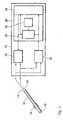
- FIG. 1shows a pacemaker 10 with an electrode lead connected to it 12.
- the electrode line 12is formed, for example, in one Ventricle of a human heart to be introduced.
- the electrode lead 12is designed as a bipolar electrode line and therefore has a ring electrode 14 and a tip electrode 16.
- the ring electrode 14 and the tip electrode 16are connected to the pacemaker via two electrical lines 18 and 20, respectively 10 and in particular a stimulation unit 22 and a detection unit 24 of the pacemaker 10 connected.
- the stimulation unit 22is designed for this purpose via the electrodes 14 and 16 Deliver bipolar stimulation pulses in the ventricle of a heart.
- the stimulation unit 22can also only be connected via an electrical line such as the electrical lead 20 connected to the tip electrode 16 to provide stimulation pulses in unipolar mode between a pacemaker case 10 and the tip electrode 16 to deliver.
- the detection unit 24is connected to the electrodes 14 and 16 for electrical Record signals from the heart. This can also be done as shown in FIG. 1 happen in bipolar mode, or alternatively in a unipolar mode via the tip electrode 16 or the ring electrode 14.
- the detection unit 24is used to record and adapt the measurement signals as possible an impedance conversion.
- the detection unit 24also controls possible blanking periods or refractory times of the pacemaker 10 in which measured signals are not evaluated or not at all first to be included.
- the signalsare thus recorded in time Assignment to stimulation pulses possibly delivered via the stimulation unit 22.
- the recorded signalsessentially set electrocardiogram obtained intracardially, which is internal to the pacemaker is forwarded to a control unit 26 for further evaluation.
- the control unit 26comprises a stimulation control unit 28, which is known per se How to control the stimulation unit 22 depending on the intracardiac obtained signals and possible further signals is used, such as physiological control signals for need-based, rate-adaptive stimulation of the heart.
- the stimulation control unit 28can also be equipped with a sensor in the atrium of a heart connected to atrial synchronous stimulation perform the ventricle in a known manner.
- the stimulation control unitalso offers 28 the function known per se, the delivery of ventricular Suppress stimulation pulses if within a predetermined time window A natural ventricular action is detected via the detection unit 24 becomes. In order to be able to control the stimulation unit 22 accordingly, the Stimulation control unit 28 connected to the stimulation unit 22.
- pacemaker 10As far as the pacemaker 10 has been described so far, it can be used in any Embodiment known from the prior art can be realized.
- An essential feature of the pacemaker 10is an evaluation unit 30, the one on the input side is taken up intracardially, for example by the detection unit 24 originating signal is supplied.
- This signalcan basically can be obtained in any known way, for ventricular ingestion evoked stimulus responses (VER) is suitable.
- the evaluation unit 30is designed the input signal from a point in time after the end a blanking period or fade out period, which in turn includes the submission of a stimulation pulse by the stimulation unit 22 begins. The The signal is evaluated after the blanking period has elapsed with reference to a signal value prevailing during the blanking period. This represents for the further evaluation of the signal practically represents the zero point.
- the evaluation of the signaltakes place in the manner described in the introduction by extracting the Signal characteristics INGR1, INGR2, CNT1, CROSS, MAX_POS and NEG_AMP. Furthermore, the evaluation unit 30 is for carrying out what has been described above Algorithm lakes trained. It has a memory 32 for everyone values to be stored and specified, in particular the values w, w1, zn, zp, a1, a2, x and AREA connected.
- the evaluation unit 30is designed, in particular, for all touch values To constantly compare NEG_AMP with the limit value zn and if the comparison result is positive a capture signal indicative of successful stimulation to deliver to the stimulation control unit 28.
- the evaluation unit 30is described under the input Conditions also include a non-capture that characterizes an unsuccessful stimulation Outputs signal.
- 1shows a variant in which this non-capture Signal directly to a control line leading to the stimulation unit 22 is given to immediately output a back-up stimulation pulse, if the evaluation unit 30 has detected a stimulation failure.
- This Non-capture signalis simultaneously output to the stimulation control unit 28.
- Design variantsare conceivable in which the evaluation unit 30 only in the event of a stimulation failure, a non-capture signal directly to the Outputs stimulation unit 22.
- both the capture signal as well as the non-capture signal or just one of the Both signalsare only delivered directly to the stimulation control unit 28 become.
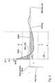
- Figure 2shows a typical, due to the polarization described Waveform, that is, a polarization artifact.
- the evaluation unit 30is formed, as well as all predetermined limit and other values, which in the memory 32 are stored.
- the "blanking level"is also during the signal amplitude prevailing in the blanking period is entered as the zero line.
- the Blanking period in the illustrated caselasts 20 milliseconds after delivery of one Stimulation pulse.
- the time of delivery of the stimulation pulseis also shown. As can be seen in Figure 2, this begins after the end the signal recorded in the blanking period with a positive signal peak value, then drops to after a certain number of sample values (CNT1) to fall below the signal prevailing during the blanking period.
- CNT1sample values
- the indicator flagis set to 1. If, as in the case shown in FIG. 2, the crossing point is outside of the time window specified by w, the indicator flag remains CROSS zero. Also shown is the positive first integral INGR1, which is the Integral of the measurement signal over time starting at the end of the blanking period up to the first negative zero crossing of the signal, and the second integral INGR2, which the remaining area integral of the measurement signal in the given by w time window in relation to that during the blanking period prevailing signal amplitude.
- the positive first integral INGR1which is the Integral of the measurement signal over time starting at the end of the blanking period up to the first negative zero crossing of the signal
- the second integral INGR2which the remaining area integral of the measurement signal in the given by w time window in relation to that during the blanking period prevailing signal amplitude.
- Figure 3shows the typical course of an evoked stimulus response and all before described parameters.
- the extracted signal featuresare as before in Uppercase letters are shown, while the limit values and other specified Parameters are labeled with small letters.
- the shown in Figure 3a signal indicating a positive stimulation success begins with a negative amplitude, the negative amount of which is greater than the limit zn.
- the evaluation unit 30corresponds to the previous one abort the algorithm described with the first sample value and can output a capture signal.
- the inventionalso applies to all other variants which are obvious to the person skilled in the art, such as the variant already indicated, in which the evaluation unit 30 directly controls the stimulation unit 22 in the non-capture case a back-up stimulation pulse with higher energy than the previous one Trigger stimulation pulse.
Landscapes
- Health & Medical Sciences (AREA)
- Cardiology (AREA)
- Heart & Thoracic Surgery (AREA)
- Engineering & Computer Science (AREA)
- Biomedical Technology (AREA)
- Nuclear Medicine, Radiotherapy & Molecular Imaging (AREA)
- Radiology & Medical Imaging (AREA)
- Life Sciences & Earth Sciences (AREA)
- Animal Behavior & Ethology (AREA)
- General Health & Medical Sciences (AREA)
- Public Health (AREA)
- Veterinary Medicine (AREA)
- Electrotherapy Devices (AREA)
Abstract
Description
Translated fromGermanDie Erfindung betrifft eine Stimulationsvorrichtung, welche eine Stimulationseinheitaufweist, die ausgebildet ist, elektrische Stimulationsimpulse zur Stimulationvon Körpergewebe abzugeben, sowie eine Auswerteeinheit, die ausgebildet ist,elektrische Signale im Zusammenhang mit der Abgabe eines Stimulationsimpulsesaufzunehmen und zur Überprüfung eines Stimulationserfolges auszuwerten.The invention relates to a stimulation device which has a stimulation unithas, which is designed, electrical stimulation pulses for stimulationdeliver body tissue, and an evaluation unit, which is designedelectrical signals associated with the delivery of a stimulation pulserecord and evaluate to check a stimulation success.
Die Erfindung betrifft insbesondere einen Herzschrittmacher, wie er üblicherweiseverwendet wird, mittels elektrischer Impulse an das Myocard eines Herzenseinen Herzrhythmus sicherzustellen, der dem hämodynamischen Bedarf einesPatienten gerecht wird. Solche Herzschrittmacher sind üblicherweise über eineElektrodenleitung mit Elektroden verbunden, die zur intrakardialen Anordnungund zur elektrischen Stimulation des Herzgewebes (Myocard) durch Abgabe elektrischerImpulse an das Myocard ausgebildet sind. Da solche Herzschrittmacherüblicherweise implantiert werden, ist es von besonderer Bedeutung, dassdie mit einem elektrischen Stimulationsimpuls abgegebene Energiemenge gerade so bemessen ist, dass das Herzgewebe sicher stimuliert wird. Ein zu energiereicherStimulationsimpuls würde die Batterie des Herzschrittmachers zu schnellerschöpfen. Auf der anderen Seite würde ein zu energiearmer Stimulationsimpulsmöglicherweise nicht ausreichen, das Herzgewebe im Sinne einer sich ausbreitendenund zur Kontraktion einer entsprechenden Herzkammer führenden Reizungzu erregen.The invention relates in particular to a pacemaker of the type normally usedis used by means of electrical impulses to the myocardium of a heartensure a heart rhythm that meets the hemodynamic needs of onePatient. Such pacemakers are usually over oneElectrode lead connected to electrodes for intracardiac placementand for electrical stimulation of the heart tissue (myocardium) by delivery of electricalPulses to the myocardium are formed. Because such pacemakersusually implanted, it is particularly important thatthe amount of energy delivered with an electrical stimulation pulseis such that the heart tissue is stimulated safely. Too energeticThe pacemaker battery would be too fastexhaust. On the other hand, the stimulation pulse would be too low in energymay not be sufficient to spread the heart tissue in the sense of aand irritation leading to contraction of a corresponding ventricleto excite.
Vor diesem Hintergrund ist es bekannt, im Zusammenhang mit der Abgabe einesStimulationsimpulses an das Myocard eine Überprüfung des Stimulationserfolgesdurch Auswertung im Zusammenhang mit der Abgabe des Stimulationsimpulsesauftretender elektrischer Signale durchzuführen, um beispielsweise im Falle einesmangelnden Stimulationserfolges einen energiereicheren Backup Stimulationsimpulsauslösen zu können. Die Stimulationserfolgskontrolle setzt das Erkenneneiner erfolgreichen Stimulation voraus, welches auch als Capture Recognitionbekannt ist. Es sind zahlreiche Vorrichtungen und Verfahren bekannt, die eineCapture Recognition ermöglichen sollen.Against this background, it is known in connection with the submission of aStimulation pulse to the myocardium a check of the stimulation successby evaluation in connection with the delivery of the stimulation pulseoccur electrical signals to perform, for example, in the case of alack of stimulation success an energy-rich backup stimulation impulseto be able to trigger. The stimulation success control sets the recognitionsuccessful stimulation, which is also known as capture recognitionis known. Numerous devices and methods are known, oneEnable capture recognition.
Es wurden bereits eine Vielzahl von Systemen zur automatischen Capture-Detektionentwickelt, die im Zusammenhang mit Herzschrittmachern dazu dienen,die An-/ Abwesenheit einer Depolarisation des Myocards im Anschluss aneinen Stimulationsimpuls zu detektieren. Diese Systeme verwenden üblicherweisesehr einfache Methoden wie eine Auswertung der Signalamplitude - d.h. desMaximalbetrags des Signals - um eine einen Stimulationserfolg kennzeichnendeDepolarisation des Myocards zu detektieren und auf diese Weise von Signalenzu unterscheiden, die mit einem mangelnden Stimulationserfolg einhergehen.Solche Systeme arbeiten zufriedenstellend, solange die Polarisationsspannungniedrig ist und ein typisches, einen Stimulationserfolg kennzeichnendes Signalauftritt. Eine Verschmelzung von stimulierten und natürlichen Herzreaktionen(Fusionsereignis) kann jedoch dazu führen, dass das auf einen Stimulationsimpulsfolgende Signal atypisch ist und von einem einfachen Algorithmus einemmangelnden Stimulationserfolg zugeordnet wird. Außerdem können starke Polarisationsspannungenein eine erfolgreiche Stimulation kennzeichnendes Signalvortäuschen. Es ist somit ein Problem, das im Myocard evozierte elektrische Signalin Anwesenheit von solchen Signal-Artefakten sicher zu detektieren, die beispielsweise auf Polarisationseffekte im Bereich der Grenzfläche zwischen Elektrodeund Körperfluid bzw. Myocard zurückgehen.A large number of systems for automatic capture detection have already been developeddeveloped that are used in connection with pacemakersthe presence / absence of myocardial depolarization afterto detect a stimulation pulse. These systems typically usevery simple methods such as an evaluation of the signal amplitude - i.e. ofMaximum amount of the signal - around a characterizing a stimulation successDetect myocardial depolarization and, in this way, signalsto differentiate, which are associated with a lack of stimulation success.Such systems work satisfactorily as long as the polarization voltageis low and is a typical signal indicative of stimulation successoccurs. A fusion of stimulated and natural heart reactions(Fusion event) can, however, result in a stimulation pulsefollowing signal is atypical and from a simple algorithm oneinsufficient stimulation success is assigned. In addition, strong polarization voltagesa signal indicative of successful stimulationto pretend. It is therefore a problem that the electrical signal evoked in the myocardiumin the presence of such signal artifacts to detect reliably, for exampleon polarization effects in the area of the interface between the electrodesand body fluid or myocardium decrease.
Es ist auch bekannt, für einen positiven Stimulationserfolg charakteristische, evozierteSignale anhand typischer Signalformen zu detektieren.It is also known to evoke characteristic of a positive stimulation successDetect signals using typical waveforms.
Leider ist das Erkennen des Stimulationserfolges in allen Fällen mit statistischenUnsicherheiten behaftet, so das nach wie vor der Wunsch besteht, eine CaptureRecognition mit höherer Spezifität und Sensitivität durchzuführen.Unfortunately, the recognition of the stimulation success is statistical in all casesThere is uncertainty, so there is still a desire to capturePerform recognition with higher specificity and sensitivity.
Erfindungsgemäß wird dies mit einer Stimulationsvorrichtung der eingangsgenanntenArt dadurch erreicht, dass die Auswerteeinheit ausgebildet ist, in demaufgenommenen Signal solche Signalmerkmale zu detektieren, die einen Fallmangelnden Stimulationserfolges kennzeichnen, und ein entsprechendes Ausgangssignalabzugeben.According to the invention, this is achieved with a stimulation device of the type mentionedArt achieved in that the evaluation unit is formed in therecorded signal to detect such signal characteristics that a casemark lack of stimulation success, and a corresponding output signalleave.
Der wesentliche Unterschied gegenüber dem Stand der Technik besteht somitdarin, dass ein mangelnder Stimulationserfolg nicht im Umkehrschluss durchNicht-Detektieren von einen Stimulationserfolg kennzeichnenden Signalmerkmalenermittelt wird, sondern direkt durch Detektieren von Signalmerkmalen, dieeinen mangelnden Stimulationserfolg kennzeichnen. Die Stimulationserfolgserkennungbeim Stand der Technik beruht darauf, Signalmerkmale zu detektieren,die einen positiven Stimulationserfolg kennzeichnen und aus dem Ausbleibensolcher, einen positiven Stimulationserfolg kennzeichnenden Signalmerkmale aufeinen mangelnden Stimulationserfolg zu schließen.The main difference compared to the prior art is thusin that a lack of stimulation success is not the reverseNon-detection of signal features that characterize a stimulation successis determined, but directly by detecting signal features thatindicate a lack of stimulation success. The stimulation success detectionin the prior art is based on detecting signal features,which mark a positive stimulation success and from the absencesuch signal features that characterize a positive stimulation successto conclude a lack of stimulation success.
Im Rahmen dieser Erfindung wird genau der umgekehrte Weg beschritten, derauf der Erkenntnis beruht, dass es tatsächlich Signalmerkmale gibt, die für einenmangelnden Stimulationserfolg spezifisch sind und die nicht lediglich auf demAusbleiben solcher Signalmerkmale beruhen, die einen positiven Stimulationserfolgkennzeichnen. Mit der erfindungsgemäßen Vorrichtung werden somit Signalmerkmale detektiert, über deren Vorhandensein und über deren Bedeutungdem Stand der Technik keinerlei Hinweise zu entnehmen ist.In the context of this invention, exactly the opposite path is followed, theis based on the knowledge that there are actually signal characteristics that exist for youlack of stimulation success are specific and not only on theAbsence of such signal characteristics are based on positive stimulation successmark. With the device according to the invention thus signal featuresdetected, about their existence and their meaningno information can be found in the prior art.
Die Erfindung beruht insbesondere auf der Erkenntnis, dass ein auf einen Stimulationsimpulsfolgendes Signal zwei separate Signalelemente aufweist, nämlichzum einen ein erstes Signalelement, das auf die Polarisation des Myocard zurückgehtund zum anderen ein zweites Signalelement, welches auf einer Polarisationim Bereich des an die Stimulationselektrode angrenzenden Gewebes bzw.Körperfluids beruht. Diese Polarisation im Bereich der Elektrodengrenzflächestellt verschwendete Energie dar und führt zu einem Signal, welches mit der positivenDetektion eines evozierten Signals im Anschluss an eine Stimulation interferiert.Zwar sind moderne Elektrodenleitungen, beispielsweise fraktale Elektrodenleitungenso gestaltet, dass die Polarisationspotentiale möglichst reduziertwerden. Dies wird typischerweise über eine Vergrößerung der Elektrodenoberflächedurch Mikrostrukturierung erzielt, wodurch kapazitive Effekte reduziert werden.Obwohl jedoch mit solchen Elektroden die Polarisation vermindert wird, wirdsie nicht gänzlich eliminiert. Außerdem variieren die Elektroden innerhalb undzwischen diversen Modellreihen hinsichtlich ihrer Effektivität im Reduzieren vonPolarisationspotentialen. Und selbst die besten Elektroden zeigen bei Stimulationsamplitudenvon mehr als 2 Volt messbare, auf die Polarisation zurückzuführendeSignalartefakte selbst noch 20 Millisekunden nach einem Stimulationsimpuls.Die Amplitude dieses Artefakts vergrößert die Spannung und verbreitert denStimulationsimpuls.The invention is based in particular on the knowledge that a stimulation impulsefollowing signal has two separate signal elements, namelyon the one hand, a first signal element which is due to the polarization of the myocardiumand on the other hand a second signal element which is based on a polarizationin the area of the tissue adjacent to the stimulation electrode orBody fluids. This polarization in the area of the electrode interfacerepresents wasted energy and leads to a signal that matches the positiveDetection of an evoked signal interferes following stimulation.Modern electrode lines are, for example, fractal electrode linesdesigned in such a way that the polarization potentials are reduced as much as possiblebecome. This is typically done by increasing the electrode surface areaachieved through microstructuring, which reduces capacitive effects.However, although with such electrodes the polarization is reducednot completely eliminating them. In addition, the electrodes vary within andbetween various model series with regard to their effectiveness in reducingPolarization potentials. And even the best electrodes show stimulation amplitudesmeasurable by more than 2 volts, due to the polarizationSignal artifacts even 20 milliseconds after a stimulation pulse.The amplitude of this artifact increases the tension and widens itStimulation pulse.
Bei der erfindungsgemäßen Stimulationsvorrichtung ist es in einer bevorzugtenAusführungsvariante erstmalig vorgesehen, für die Polarisation charakteristischeSignalartefakte als einen mangelnden Stimulationserfolg kennzeichnendes Signalmerkmalzu detektieren.In the stimulation device according to the invention, it is preferredDesign variant provided for the first time, characteristic of the polarizationSignal artifacts as a characteristic of a lack of stimulation successto detect.
Diese bevorzugte Ausführungsvariante beruht auf der Erkenntnis, das derartige,auf die Polarisation zurückzuführende Signalartefakte regelmäßig eine ähnlicheMorphologie aufweisen. Diese Erkenntnisse wurden durch Versuche gewonnen,bei denen Elektrodenleitungen in einer Salzlösung auf die Signalformen hin untersuchtwurden, die sich im Anschluss an die Abgabe eines Impulses an dieSalzlösung ergeben.This preferred embodiment variant is based on the knowledge that suchSignal artifacts due to polarization regularly have a similar oneHave morphology. This knowledge was gained through experimentsin which electrode lines in a saline solution are examined for the signal shapesthat followed the delivery of an impulse to theSaline solution.
Auf der anderen Seite wurde beobachtet, dass im Menschen aufgenommeneElektrogramme beinahe jede Form annehmen können. Solche Variationen vonElektrogramm - Morphologien können sich sowohl bei verschiedenen Messungenan einem Patient als auch bei Messung an verschiedenen Patienten ergeben.Unterschiede zwischen den Messungen an einem Patienten ergeben sichtypischerweise aus Fusionsereignissen, Atmungseinflüssen einer anodalen Stimulationoder aus anderen, nicht identifizierten Gründen. Unterschiede zwischenMessungen an unterschiedlichen Patienten ergeben sich vermutlich aus Unterschiedenin der kardialen Pathologie, der Elektrodenleitungsposition oder derElektrodenpolarisation.On the other hand, it has been observed that ingested in humansElectrograms can take almost any form. Such variations ofElectrogram morphologies can occur both in different measurementson one patient as well as when measured on different patients.There are differences between the measurements on a patienttypically from fusion events, breathing effects of anodal stimulationor for other, unidentified reasons. differences betweenMeasurements on different patients presumably result from differencesin cardiac pathology, lead position, orElectrode polarization.
Auf Basis der Polarisationssignalform wurden charakteristische Merkmale, Signaturendes Polarisationspotentials in Form einer Vielzahl von Signalmerkmalenund Schwellwerten extrahiert. Bevorzugte Ausführungsvarianten der Erfindungstellen auf diese Signalmerkmale und Schwellwerte ab.Based on the polarization waveform, characteristic features, signaturesthe polarization potential in the form of a variety of signal featuresand threshold values are extracted. Preferred embodiments of the inventionare based on these signal characteristics and threshold values.
Zu den vorzugsweise detektierten Merkmalen zählen ein erstes Integral INGR1des nach Ablauf einer Blanking Periode nach Abgabe eines Stimulationsimpulsesgemessen Signals über die Zeit bis zu dem Zeitpunkt, indem das gemesseneSignal den während der Blanking Periode herrschenden Signalwert kreuzt. Dieseserste Signal ist in der Regel positiv, da das im Anschluss an die BlankingPeriode gemessene Signal üblicherweise über den Signalwert während derBlanking Periode liegt. Entsprechend ist die Auswerteeinheit vorzugsweise dazuausgebildet, das erste Integral INGR1 zu bestimmen.The preferably detected features include a first integral INGR1after a blanking period after the delivery of a stimulation pulsemeasured signal over time up to the time by the measuredSignal crosses the signal value prevailing during the blanking period. ThisThe first signal is usually positive, as it follows the blankingPeriod measured signal usually over the signal value during theBlanking period lies. The evaluation unit is preferably accordinglytrained to determine the first integral INGR1.
Ein weiteres vorzugsweise aufgenommenes und ermitteltes Signalmerkmal istein zweites Integral INGR2 des gemessenen Signals, welches über einen Zeitraumgebildet wird, welcher mit dem Zeitpunkt beginnt, für den das erste Integralendet und welcher mit dem Ende eines vorgegebenen Zeitfensters endet, wobeidas vorgegebene Zeitfenster mit dem Ablauf der Blanking Periode beginnt. Entsprechendist die Auswerteeinheit vorzugsweise dazu ausgebildet, auch daszweite Integral INGR2 zu bestimmen.Another preferably recorded and determined signal feature isa second integral INGR2 of the measured signal, which over a period of timeis formed, which begins at the time for which the first integralends and which ends with the end of a predetermined time window, wherebythe specified time window begins with the expiry of the blanking period. Correspondingthe evaluation unit is preferably designed to also do thisto determine second integral INGR2.
Ein weiteres Signalmerkmal, welches vorzugsweise durch eine entsprechendausgebildete Auswertereinheit aufgenommen wird, ist die Anzahl CNT1 derTastwerte des aufgenommenen Signals, welche in die Zeit fallen, über die daserste Integral gebildet wird. Die Stimulationsvorrichtung ist in diesem Falle dazuausgebildet, das aufgenommene Signal zeitdiskret abzutasten, so dass das aufgenommeneSignal in Form einer Vielzahl zeitdiskreter Tastwerte (samples) vorliegt.Zum Zählen der Tastwerte innerhalb eines Zeitraumes weist die Auswerteeinheitvorzugsweise einen Zähler auf.Another signal feature, which is preferably by a correspondingtrained evaluation unit is added, the number is CNT1Sample values of the recorded signal, which fall in the time over which thefirst integral is formed. The stimulation device is in this casetrained to sample the recorded signal discretely, so that the recordedSignal in the form of a large number of time-discrete sample values.The evaluation unit has a counter for counting the scanning values within a period of timepreferably a counter.
Ein weiteres zusätzlich oder auch alternativ aufgenommenes Signalmerkmal bestehtin einem Indikator-Flag CROSS, dessen Wert davon abhängt, ob das gemesseneSignal während der Zeitdauer für die Bestimmung des zweiten Integralsdie während der Blanking Periode herrschende Signalamplitude kreuzt. Wennder Signalwert während der Blanking Amplitude für das anschließend gemesseneSignal den Referenz- oder Nullwert bildet, kennzeichnet das Indikator-FlagCROSS=1 das Vorliegen eines Nulldurchgangs für das gemessene Signal währendder Zeit, über die das zweite Integral gebildet wird. Liegt kein Nulldurchgangvor ist das Indikator-Flag CROSS=0. Die Auswerteeinheit ist vorzugsweise zumBestimmen und Speichern des binären Wertes des Indikator-Flags CROSS ausgebildet.Another additional or alternatively recorded signal feature existsin an indicator flag CROSS, the value of which depends on whether the measuredSignal during the period for the determination of the second integralcrosses the signal amplitude prevailing during the blanking period. Ifthe signal value during the blanking amplitude for the subsequently measuredSignal forms the reference or zero value, identifies the indicator flagCROSS = 1 the presence of a zero crossing for the measured signal duringthe time over which the second integral is formed. There is no zero crossingin front is the indicator flag CROSS = 0. The evaluation unit is preferably forDetermination and storage of the binary value of the indicator flag CROSS trained.
Ein weiteres Signalmerkmal ist der maximale positive Tastwert des nach Abschlussder Blanking Periode aufgenommenen, gemessenen Signals unterNichtberücksichtigung der ersten x Tastwerte nach Ablauf der Blanking Periode.Es wird somit vorzugsweise der x+1. Tastwert nach Ablauf der Blanking Periodeals maximaler positiver Tastwert MAX_POS aufgenommen. Der Tastwert wird -wie das gesamte nach Ablauf der Blanking Periode gemessene Signal - relativzu der während der Blanking Periode herrschenden Signalamplitude bestimmt.Außerdem werden vorzugsweise alle im Bezug auf die Signalamplitude währendder Blanking Periode negativen Tastwerte als NEG_AMP gespeichert. Die Auswerteeinheitist entsprechend vorzugsweise zum Bestimmen des maximalen positivenTastwertes MAX_POS sowie der negativen Tastwerte NEG_AMP undzum Speichern dieser Werte ausgebildet.
Zur weiteren Analyse der im vorbeschriebenen Sinne bestimmten Signalmerkmaleweist die Auswerteeinheit vorzugsweise verschiedene Schwellwerteinheiten auf, die im wesentlichen einen Speicher für den jeweils vorgegebenen Wert desentsprechenden Schwellwertes umfassen, sowie eine Vergleichseinheit, die einSignal ausgibt, welches davon abhängt, ob der vorgegebene Schwellwert über-oder unterschritten wird. Folgende Schwellwerte bzw. Parameter sind vorzugsweisevorgesehen:
- w
- Breite des Zeitfensters in Millisekunden oder Anzahl von Tastwerten
- w1
- Grenzwert für einen ersten positiven Signalabschnitt, der durch dieAnzahl der Tastwerte gegeben ist, über die das erste Integral gebildetwird (CNT1)
- zn
- Negativer Grenzwert für die auf die Signalamplitude während derBlanking Periode bezogenen Tastwerte
- zp
- Grenzwert für den maximalen positiven Tastwert MAX_POS fallsder positive Signalabschnitt breiter ist als durch w1 vorgegeben
- a1
- Ein Grenzwert für eine Fläche AREA welche aus dem ersten unddem zweiten Integral (INGR1, INGR2) gebildet wird als Kennzeichenfür ein Nicht-Capture
- a 2
- Grenzwert für die Fläche AREA, oberhalb dessen ein Capture vorliegt
- x
- Die bereits vorgenannte Anzahl von Tastwerten nach Ende derBlanking Periode, die für die Bestimmung von MAX_POS ignoriertwerden
For further analysis of the signal characteristics determined in the above-described sense, the evaluation unit preferably has various threshold value units, which essentially comprise a memory for the respectively predefined value of the corresponding threshold value, and a comparison unit which outputs a signal which depends on whether the predefined threshold value exceeds - or falls below. The following threshold values or parameters are preferably provided:
- w
- Width of the time window in milliseconds or number of samples
- w1
- Limit value for a first positive signal section, which is given by the number of sample values over which the first integral is formed (CNT1)
- zn
- Negative limit for the key values related to the signal amplitude during the blanking period
- zp
- Limit value for the maximum positive pulse value MAX_POS if the positive signal section is wider than specified by w1
- a1
- A limit value for an area AREA which is formed from the first and the second integral (INGR1, INGR2) as a sign for a non-capture
- a 2
- Limit value for the AREA area above which there is a capture
- x
- The already mentioned number of sample values after the end of the blanking period, which are ignored for the determination of MAX_POS
Die Auswerteeinheit ist weiterhin vorzugsweise ausgebildet, eine Ermittlung einernicht erfolgreichen Stimulation (Non-Capture) basierend auf den zuvor eingeführtenSignalmerkmalen und Grenzwerten nach folgendem Algorithmus durchzuführen:
Die Auswerteeinheit ist somit vorzugsweise dazu ausgebildet die folgendenSchwellwertvergleiche durchzuführen und entsprechende Ergebnisse zu liefern:The evaluation unit is thus preferably designed to do the followingCarrying out threshold comparisons and delivering corresponding results:
Wenn NEG_AMP größer ist als zn gibt die Auswerteeinheit ein eine erfolgreicheStimulation kennzeichnendes Capture-Signal aus.
Wenn die Anzahl der Tastwerte CNT1 größer ist als w1, dann wird der FlächenwertAREA als Summe aus dem ersten Integral INGR1 und dem zweiten IntegralINGR2 gebildet, ansonsten ist der Flächenwert AREA gleich dem zweiten IntegralINGR2. Anschließend wird die Fläche AREA mit dem Schwellwert a1 verglichenund wenn AREA kleiner ist als a1 ein eine erfolglose Stimulation kennzeichnendesNon-Capture Signal ausgegeben. Falls diese Bedingung nicht erfülltist prüft die Auswerteeinheit, ob die Anzahl CNT1 größer ist als der Grenzwert w1und führt, falls dies der Fall ist, einen Vergleich des maximalen positiven TastwertesMAX_POS mit dem Grenzwert zp durch. Ist MAX_POS kleiner ist als zpwird ein Non-Capture Signal ausgegeben, ansonsten ein Capture Signal. Fallskeine der beiden Bedingungen AREA kleiner ist als a1 und CNT1 größer ist alsw1 gegeben sind, vergleicht die Auswerteeinheit den Flächenwert AREA mit demGrenzwert a2 und gibt für den Fall, dass AREA größer als a2 ist, ein CaptureSignal aus. Trifft auch diese Bedingung nicht zu, prüft die Auswerteeinheit, obdas Indikator-Flag CROSS auf 1 gesetzt ist, ob also das gemessene Signal imBereich des zweiten Integrals einen Nulldurchgang aufweist. In diesem Fall wird ein Capture Signal ausgegeben. Trifft auch diese Bedingung nicht zu, gibt dieAuswerteeinheit ein Nicht-Capture Signal aus.If NEG_AMP is greater than zn, the evaluation unit outputs a capture signal which characterizes successful stimulation.
If the number of key values CNT1 is greater than w1, then the area value AREA is formed as the sum of the first integral INGR1 and the second integral INGR2, otherwise the area value AREA is equal to the second integral INGR2. The AREA area is then compared with the threshold value a1 and, if AREA is less than a1, a non-capture signal characterizing an unsuccessful stimulation is output. If this condition is not met, the evaluation unit checks whether the number CNT1 is greater than the limit value w1 and, if this is the case, compares the maximum positive pulse value MAX_POS with the limit value zp. If MAX_POS is less than zp, a non-capture signal is output, otherwise a capture signal. If neither of the two conditions AREA is less than a1 and CNT1 is greater than w1, the evaluation unit compares the area value AREA with the limit value a2 and outputs a capture signal in the event that AREA is greater than a2. If this condition also does not apply, the evaluation unit checks whether the indicator flag CROSS is set to 1, that is to say whether the measured signal has a zero crossing in the region of the second integral. In this case, a capture signal is output. If this condition also does not apply, the evaluation unit outputs a non-capture signal.
Darüber hinaus ist die Auswerteeinheit vorzugsweise dazu ausgebildet, schonbeim Aufnehmen der Tastwerte für das gemessene Signal ständig ein Vergleichder Tastwerte mit dem Schwellwert für die negative Signalamplitude zn durchzuführen.Falls ein negativer Tastwert NEG_AMP kleiner ist als zn (oder mit anderenWorten einen größeren negativen Betrag hat als zn) wird das gemesseneSignal sofort als einen Stimulationserfolg kennzeichnendes Signal klassifiziertund dementsprechend ein Capture Signal ausgegeben. Diese Überprüfung führtdie Auswerteeinheit vorzugsweise Tastwert für Tastwert parallel zu dem zuvorbeschriebenen Algorithmus durch, und bricht diesen Algorithmus sofort ab, fallsein Tastwert NEG_AMP kleiner ist als zn. Der zuvor beschriebene Algorithmuswird nur dann bis zum Ende fortgeführt, wenn die Bedingung NEG_AMP < znwährend des Aufnehmens der Tastwerte nicht erfüllt wird. Dies spart in vorteilhafterWeise Rechenkapazität und Energie.In addition, the evaluation unit is preferably designed to bea constant comparison when recording the key values for the measured signalof the pulse values with the threshold value for the negative signal amplitude zn.If a negative sample value NEG_AMP is smaller than zn (or with othersWords has a greater negative magnitude than zn) is the measuredSignal immediately classified as a signal indicating a stimulation successand accordingly a capture signal is output. This review leadsthe evaluation unit preferably a sample value for a sample value in parallel with the previous onedescribed algorithm, and aborts this algorithm immediately ifa sample value NEG_AMP is less than zn. The algorithm described earlieris only continued until the end if the condition NEG_AMP <znis not fulfilled during the recording of the touch values. This saves in an advantageous mannerWise computing capacity and energy.
Soweit eine kurze Beschreibung der bevorzugten Ausgestaltung der Erfindung.So much for a brief description of the preferred embodiment of the invention.
Diese soll nun anhand eines Ausführungsbeispiels und mit Hilfe der Figuren nähererläutert werden.This is now to be explained in more detail using an exemplary embodiment and with the aid of the figuresare explained.
Von den Figuren zeigen
- Fig.1:
- ein schematisches Blockschaltbild eines erfindungsgemäßen Herzschrittmachers
- Fig.2:
- eine Darstellung einer typischerweise nach Abgabe eines Stimulationsimpulsesaufgenommenen Signals über die Zeit mit den typischen Signalmerkmalenfür ein Polarisations-Artefakt samt Darstellung der vorzugsweiseaufgenommen und vorgegebenen Signalmerkmale undSchwellwerte;
- Fig.3:
- eine schematische Darstellung einer typischen Signalform eines nacheinem Stimulationsimpuls aufgenommenen Signals im Falle einer erfolgreichen Stimulation mit den dazugehörigen aufgenommenen Signalmerkmalenund Schwellwerten;
- Fig.4:
- eine Signalform des aufgenommenen Signals nach erfolgreicher Stimulationmit anfänglicher positiver Amplitude
- Fig.1:
- is a schematic block diagram of a pacemaker according to the invention
- Figure 2:
- a representation of a signal typically recorded after delivery of a stimulation pulse over time with the typical signal characteristics for a polarization artifact, including a representation of the signal characteristics and threshold values that are preferably recorded and predefined;
- Figure 3:
- a schematic representation of a typical signal shape of a signal recorded after a stimulation pulse in the event of successful stimulation with the associated recorded signal features and threshold values;
- Figure 4:
- a waveform of the recorded signal after successful stimulation with an initial positive amplitude
Figur 1 zeigt einen Herzschrittmacher 10 mit daran angeschlossener Elektrodenleitung12. Die Elektrodenleitung 12 ist ausgebildet um beispielsweise in einenVentrikel eines menschlichen Herzens eingeführt zu werden. Die Elektrodenleitung12 ist als bipolare Elektrodenleitung ausgeführt und besitzt daher eine Ringelektrode14 und eine Spitzenelektrode 16. Die Ringelektrode 14 und die Spitzenelektrode16 sind über zwei elektrische Leitungen 18 bzw. 20 mit dem Herzschrittmacher10 und insbesondere einer Stimulationseinheit 22 sowie einer Detektionseinheit24 des Herzschrittmachers 10 verbunden.FIG. 1 shows a
Die Stimulationseinheit 22 ist dazu ausgebildet über die Elektroden 14 und 16bipolare Stimulationsimpulse im Ventrikel eines Herzens abzugeben. Alternativkann die Stimulationseinheit 22 auch nur über eine elektrische Leitung wie dieelektrische Leitung 20 mit der Spitzenelektrode 16 verbunden sein, um Stimulationsimpulseim unipolaren Modus zwischen einem Gehäuse des Herzschrittmachers10 und der Spitzenelektrode 16 abzugeben.The
Die Detektionseinheit 24 ist mit den Elektroden 14 und 16 verbunden um elektrischeSignale des Herzens aufzunehmen. Auch dies kann wie in Figur 1 dargestelltim bipolaren Modus geschehen, oder alternativ in einem unipolaren Modusüber die Spitzenelektrode 16 oder die Ringelektrode 14. Die Detektionseinheit 24dient der Signalaufnahme und der Anpassung der Messsignale wie möglicherweiseeiner Impedanzwandlung. Außerdem steuert die Detektionseinheit 24mögliche Ausblendzeiten (Blanking Perioden) oder Refraktärzeiten des Herzschrittmachers10, in denen gemessene Signale nicht ausgewertet oder gar nichterst aufgenommen werden. Die Aufnahme der Signale erfolgt somit in zeitlicherZuordnung zu möglicherweise über die Stimulationseinheit 22 abgegebenen Stimulationsimpulsen.Die aufgenommenen Signale stellen im Wesentlichen einintrakardial gewonnenes Elektrokardiogramm dar, welches schrittmacher-internzur weiteren Auswertung an eine Steuereinheit 26 weitergeleitet wird. Die Steuereinheit 26 umfasst eine Stimulationssteuereinheit 28, die in an sich bekannterWeise der Ansteuerung der Stimulationseinheit 22 in Abhängigkeit der intrakardialgewonnenen Signale und möglicher weiterer Signale dient, wie beispielsweisephysiologischen Steuersignalen zur bedarfsgerechten, ratenadaptiven Stimulationdes Herzens. Die Stimulationssteuereinheit 28 kann auch mit einem Sensorim Vorhof eines Herzens verbunden sein, um eine atriumssynchrone Stimulationdes Ventrikels in bekannter Weise durchzuführen. Außerdem bietet die Stimulationssteuereinheit28 die an sich bekannte Funktion, die Abgabe von ventrikulärenStimulationsimpulsen zu unterdrücken, wenn innerhalb eines vorgegebenen Zeitfenstersüber die Detektionseinheit 24 eine natürliche Ventrikelaktion detektiertwird. Um die Stimulationseinheit 22 entsprechend ansteuern zu können, ist dieStimulationssteuereinheit 28 mit der Stimulationseinheit 22 verbunden.The
Soweit der Herzschrittmacher 10 bis hierher beschrieben wurde, kann er in jederaus dem Stand der Technik bekannten Ausführungsform realisiert sein.As far as the
Wesentliches Merkmal des Herzschrittmachers 10 ist eine Auswerteeinheit 30,der eingangsseitig ein intrakardial aufgenommenes, beispielsweise von der Detektionseinheit24 stammendes Signal zugeführt wird. Dieses Signal kann grundsätzlichauf jede bekannte Art gewonnen werden, die zum Aufnehmen ventrikulärerevozierter Reizantworten (VER) geeignet ist. Die Auswerteeinheit 30 ist ausgebildet,dass eingangsseitig anliegende Signal von einem Zeitpunkt nach Endeeiner Blanking Periode oder Ausblendzeit auszuwerten, die ihrerseits mit der Abgabeeines Stimulationsimpulses durch die Stimulationseinheit 22 beginnt. DieAuswertung des Signals nach Ablauf der Blanking Periode erfolgt mit Bezug aufeinen während der Blanking Periode herrschenden Signalwert. Dieser stellt fürdie weitere Auswertung des Signals praktisch den Nullpunkt dar. Die Auswertungdes Signals erfolgt auf die einleitend beschriebene Weise durch Extraktion derSignalmerkmale INGR1, INGR2, CNT1, CROSS, MAX_POS und NEG_AMP.Weiterhin ist die Auswerteeinheit 30 zur Durchführung des eingangsbeschriebenenAlgorithmussees ausgebildet. Sie ist dazu mit einem Speicher 32 für alle zuspeichernden und vorzugebenden Werte, insbesondere die Werte w, w1, zn, zp,a1, a2, x und AREA verbunden.An essential feature of the
Die Auswerteeinheit 30 ist insbesondere dazu ausgebildet, alle TastwerteNEG_AMP ständig mit dem Grenzwert zn zu vergleichen und bei positiven Vergleichsergebnisein eine erfolgreiche Stimulation kennzeichnendes Capture-Signalan die Stimulationssteuereinheit 28 abzugeben.The
Wesentlich ist jedoch, dass die Auswerteeinheit 30 unter den Eingangs beschriebenenBedingungen auch ein eine erfolglose Stimulation kennzeichnendes Non-CaptureSignal ausgibt. In Figur 1 ist eine Variante dargestellt, in der dieses Non-CaptureSignal direkt auf eine zur Stimulationseinheit 22 führende Steuerleitunggegeben wird, um unmittelbar einen Back-up Stimulationsimpuls auszugeben,falls die Auswerteeinheit 30 einen Stimulationsmisserfolg detektiert hat. DiesesNon-Capture Signal wird gleichzeitig an die Stimulationssteuereinheit 28 abgegeben.Es sind Ausführungsvarianten denkbar, in denen die Auswerteeinheit 30nur im Falle eines Stimulationsmisserfolges ein Non-Capture Signal direkt an dieStimulationseinheit 22 abgibt. In einer anderen Ausführungsvariante können sowohldas Capture Signal als auch das Non-Capture Signal oder nur eines derbeiden Signale ausschließlich direkt an die Stimulationssteuereinheit 28 abgegebenwerden.It is essential, however, that the
Figur 2 zeigt eine typische, auf die beschriebene Polarisation zurückgehendeSignalform, das heißt einen Polarisationsartefakt. In Figur 2 sind all die vorgenanntenSignalmerkmale eingetragen, zu deren Extraktion die Auswerteeinheit30 ausgebildet ist, sowie alle vorgegebenen Grenz- und sonstigen Werte, die indem Speicher 32 gespeichert sind. Als "Blanking level" ist außerdem die währendder Blanking Periode herrschende Signalamplitude als Nulllinie eingetragen. DieBlanking Periode dauert im dargestellten Fall 20 Millisekunden nach Abgabe einesStimulationsimpulses. Der Zeitpunkt der Abgabe des Stimulationsimpulsesist ebenfalls dargestellt. Wie Figur 2 zu entnehmen ist, beginnt das nach Endeder Blanking Periode aufgenommene Signal mit einem positiven Signalspitzenwert,fällt dann ab, um nach einer bestimmten Anzahl von Tastwerten (CNT1)unter das während der Blanking Periode herrschende Signal zu fallen. Das dannnegative Signal steigt nach einiger Zeit wieder an und kreuzt das während derBlanking Periode herrschende Signalniveau. Wenn dieser Kreuzpunkt innerhalbdes durch w vorgegebenen Zeitfensters liegt, wird das Indikator-Flag auf 1 gesetzt.Liegt der Kreuzungspunkt - wie in dem in Figur 2 dargestellten Fall - außerhalb des durch w vorgegebenen Zeitfensters, bleibt das Indikator-FlagCROSS null. Dargestellt ist auch das positive erste Intergral INGR1, welches dasIntegral des Messsignals über die Zeit beginnend mit Ende der Blanking Periodebis zum ersten negativen Nulldurchgang des Signals ist, sowie das zweite IntegralINGR2, welches das verbleibende Flächenintegral des Meßsignals in demdurch w vorgegebenen Zeitfenster in Bezug auf die während der Blanking Periodeherrschende Signalamplitude darstellt.Figure 2 shows a typical, due to the polarization describedWaveform, that is, a polarization artifact. In Figure 2 are all of the aboveSignal characteristics entered, for their extraction the
Figur 3 zeigt den typischen Verlauf einer evozierten Reizantwort und aller zuvorbeschriebenen Parameter. Die extrahierten Signalmerkmale sind wie zuvor inGroßbuchstaben dargestellt, während die Grenzwerte und sonstige vorzugebenenParameter mit kleinen Buchstaben bezeichnet sind. Das in Figur 3 dargestellte,einen positiven Stimulationserfolg kennzeichnende Signal beginnt mit einernegativen Amplitude, deren negativer Betrag größer ist, als der Grenzwertzn. Bereits mit dem ersten Tastwert steht somit fest, dass das Signal einem positivenStimulationserfolg zuzuordnen ist, so dass die Auswerteeinheit 30 den zuvorbeschriebenen Algorithmus bereits mit dem ersten Tastwert abbrechen undein Capture Signal ausgeben kann.Figure 3 shows the typical course of an evoked stimulus response and all beforedescribed parameters. The extracted signal features are as before inUppercase letters are shown, while the limit values and other specifiedParameters are labeled with small letters. The shown in Figure 3a signal indicating a positive stimulation success begins with anegative amplitude, the negative amount of which is greater than the limitzn. Already with the first sample value it is clear that the signal is positiveSuccess of stimulation is to be assigned, so that the
Wie in Figur 4 dargestellt kann das im Falle eines Stimulationserfolges gewonneneSignal auch mit einem positiven Signalspitzenwert beginnen. Auch in diesemFalle erlaubt die Auswerteeinheit 30 eine zuverlässige Erkennung eines Stimulationsmisserfolgesund gibt im Falle der in Figur 4 dargestellten Signalform keinNon-Capture sondern ein Capture Signal aus.As shown in FIG. 4, this can be achieved in the event of a stimulation successSignal also start with a positive signal peak. Also in thisIf the
Über die in dem Ausführungsbeispiel dargestellte Variante hinaus erstreckt sichdie Erfindung auch auf alle anderen, für den Fachmann naheliegenden Varianten,wie beispielsweise die bereits angedeutete Variante, bei der die Auswerteeinheit30 die Stimulationseinheit 22 im Non-Capture Fall direkt ansteuert, umeinen Back-up Stimulationsimpuls mit höherer Energie als dem vorangegangenenStimulationsimpuls auszulösen.It extends beyond the variant shown in the exemplary embodimentthe invention also applies to all other variants which are obvious to the person skilled in the art,such as the variant already indicated, in which the
Claims (8)
Translated fromGermandadurch gekennzeichnet, dass die Auswerteinheit ausgebildet ist, in demaufgenommenen Signal solche Signalmerkmale zu detektieren, die einenFall mangelnden Stimulationserfolges kennzeichnen, und ein entsprechendesAusgangssignal abzugeben.Stimulation device which has a stimulation unit which is designed to emit electrical stimulation pulses for the stimulation of body tissue, and an evaluation unit which is designed to receive electrical signals in connection with the emitting of a stimulation pulse and to evaluate them for checking a stimulation success,
characterized in that the evaluation unit is designed to detect in the recorded signal those signal features which characterize a case of insufficient stimulation success, and to emit a corresponding output signal.
Applications Claiming Priority (4)
| Application Number | Priority Date | Filing Date | Title |
|---|---|---|---|
| US26224301P | 2001-01-17 | 2001-01-17 | |
| US262243P | 2001-01-17 | ||
| DE10128982ADE10128982A1 (en) | 2001-01-17 | 2001-06-08 | Pacemaker for stimulating a heart has a stimulation unit emitting electric impulses to stimulate bodily tissue and an evaluatory unit to record electric signals with these impulses and assess success levels of stimulation. |
| DE10128982 | 2001-06-08 |
Publications (3)
| Publication Number | Publication Date |
|---|---|
| EP1224952A2true EP1224952A2 (en) | 2002-07-24 |
| EP1224952A3 EP1224952A3 (en) | 2004-03-17 |
| EP1224952B1 EP1224952B1 (en) | 2008-01-16 |
Family
ID=26009531
Family Applications (1)
| Application Number | Title | Priority Date | Filing Date |
|---|---|---|---|
| EP02090018AExpired - LifetimeEP1224952B1 (en) | 2001-01-17 | 2002-01-17 | Stimulation device with capture verification |
Country Status (3)
| Country | Link |
|---|---|
| EP (1) | EP1224952B1 (en) |
| AT (1) | ATE383891T1 (en) |
| DE (1) | DE50211539D1 (en) |
Cited By (1)
| Publication number | Priority date | Publication date | Assignee | Title |
|---|---|---|---|---|
| RU2405590C1 (en)* | 2009-05-28 | 2010-12-10 | Александр Николаевич Александров | Deimplanted pacemaker connector |
Citations (5)
| Publication number | Priority date | Publication date | Assignee | Title |
|---|---|---|---|---|
| US5417718A (en) | 1992-11-23 | 1995-05-23 | Pacesetter, Inc. | System for maintaining capture in an implantable pulse generator |
| US5697957A (en) | 1996-08-29 | 1997-12-16 | Pacesetter Ab | Adaptive method and apparatus for extracting an evoked response component from a sensed cardiac signal by suppressing electrode polarization components |
| US5861013A (en) | 1997-04-29 | 1999-01-19 | Medtronic Inc. | Peak tracking capture detection circuit and method |
| US5873898A (en) | 1997-04-29 | 1999-02-23 | Medtronic, Inc. | Microprocessor capture detection circuit and method |
| US5941903A (en) | 1998-04-30 | 1999-08-24 | Cardiac Pacemakers, Inc | Pacemaker for detection of evoked response |
Family Cites Families (7)
| Publication number | Priority date | Publication date | Assignee | Title |
|---|---|---|---|---|
| US5172690A (en)* | 1990-10-26 | 1992-12-22 | Telectronics Pacing Systems, Inc. | Automatic stimulus artifact reduction for accurate analysis of the heart's stimulated response |
| US5443485A (en)* | 1993-09-08 | 1995-08-22 | Intermedics, Inc. | Apparatus and method for capture detection in a cardiac stimulator |
| US5601615A (en)* | 1994-08-16 | 1997-02-11 | Medtronic, Inc. | Atrial and ventricular capture detection and threshold-seeking pacemaker |
| US5571144A (en)* | 1995-12-18 | 1996-11-05 | Intermedics, Inc. | Method of verifying capture of the atrium by a cardiac stimulator |
| US6067472A (en)* | 1997-03-12 | 2000-05-23 | Medtronic, Inc. | Pacemaker system and method with improved evoked response and repolarization signal detection |
| SE9800407D0 (en)* | 1998-02-12 | 1998-02-12 | Pacesetter Ab | Heart stimulator |
| US6175766B1 (en)* | 1999-03-30 | 2001-01-16 | Pacesetter, Inc. | Cardiac pacemaker autothreshold arrangement and method with reliable capture |
- 2002
- 2002-01-17EPEP02090018Apatent/EP1224952B1/ennot_activeExpired - Lifetime
- 2002-01-17ATAT02090018Tpatent/ATE383891T1/ennot_activeIP Right Cessation
- 2002-01-17DEDE50211539Tpatent/DE50211539D1/ennot_activeExpired - Lifetime
Patent Citations (6)
| Publication number | Priority date | Publication date | Assignee | Title |
|---|---|---|---|---|
| US5417718A (en) | 1992-11-23 | 1995-05-23 | Pacesetter, Inc. | System for maintaining capture in an implantable pulse generator |
| US5697957A (en) | 1996-08-29 | 1997-12-16 | Pacesetter Ab | Adaptive method and apparatus for extracting an evoked response component from a sensed cardiac signal by suppressing electrode polarization components |
| EP0826392A2 (en) | 1996-08-29 | 1998-03-04 | Pacesetter AB | Adaptive method and apparatus for extracting an evoked response component from a sensed cardiac signal by suppressing electrode polarization components |
| US5861013A (en) | 1997-04-29 | 1999-01-19 | Medtronic Inc. | Peak tracking capture detection circuit and method |
| US5873898A (en) | 1997-04-29 | 1999-02-23 | Medtronic, Inc. | Microprocessor capture detection circuit and method |
| US5941903A (en) | 1998-04-30 | 1999-08-24 | Cardiac Pacemakers, Inc | Pacemaker for detection of evoked response |
Cited By (1)
| Publication number | Priority date | Publication date | Assignee | Title |
|---|---|---|---|---|
| RU2405590C1 (en)* | 2009-05-28 | 2010-12-10 | Александр Николаевич Александров | Deimplanted pacemaker connector |
Also Published As
| Publication number | Publication date |
|---|---|
| EP1224952B1 (en) | 2008-01-16 |
| EP1224952A3 (en) | 2004-03-17 |
| ATE383891T1 (en) | 2008-02-15 |
| DE50211539D1 (en) | 2008-03-06 |
Similar Documents
| Publication | Publication Date | Title |
|---|---|---|
| DE10128982A1 (en) | Pacemaker for stimulating a heart has a stimulation unit emitting electric impulses to stimulate bodily tissue and an evaluatory unit to record electric signals with these impulses and assess success levels of stimulation. | |
| DE60220751T2 (en) | Pacemaker with improved capture confirmation | |
| DE69726356T2 (en) | Apparatus for deriving a component of an evoked response from a sampled cardiac signal by suppressing electrode polarization components | |
| DE69807986T2 (en) | Implantable pacemaker | |
| EP1769823B1 (en) | Detector for atrial fibrillation and atrial flutter | |
| DE69319641T2 (en) | Detection of tachycardia and cardiac fibrillation | |
| DE69333006T2 (en) | IMPLANTABLE HEART PACEMAKER WITH SYSTEM FOR AUTOMATICALLY DETECTING A SUCCESSFUL STIMULATION | |
| DE69827420T2 (en) | Pacemaker with variable stimulation energy | |
| DE69820860T2 (en) | PACEMAKER | |
| DE102007054178A1 (en) | Biventricular cardiac stimulator | |
| EP1774988B1 (en) | Implantable cardiac vector determination device | |
| EP2353644A1 (en) | Cardioverter/defibrillator and signal processing device for classifying intracardiac signals | |
| EP0583499B1 (en) | Method for detecting cardial ventricular fibrillation and means for detection and treating of cardial ventricular fibrillation | |
| EP2676697B1 (en) | Dislocation sensor | |
| EP1582234B1 (en) | Pacemaker | |
| DE69420235T2 (en) | Device for analyzing the electrical signals of a heart | |
| EP1108390A2 (en) | Device for recognition of effect of extrasystols on the circulatory system | |
| DE69431818T2 (en) | Device for distinguishing between arterial and ventricular depolarizations | |
| DE69632673T2 (en) | Pacemaker with evoked response detection | |
| EP2181648A2 (en) | Single chamber heart simulator | |
| EP1224952B1 (en) | Stimulation device with capture verification | |
| EP2111894B1 (en) | Heart stimulator with stimulation success control | |
| DE102019121719A1 (en) | Implantable defibrillation system | |
| EP2111893A1 (en) | Ventricular heart stimulator | |
| EP2140910B1 (en) | Heart stimulator for treating cardiac tachyarrhythmias |
Legal Events
| Date | Code | Title | Description |
|---|---|---|---|
| REG | Reference to a national code | Ref country code:SE Ref legal event code:TRGR | |
| PUAI | Public reference made under article 153(3) epc to a published international application that has entered the european phase | Free format text:ORIGINAL CODE: 0009012 | |
| AK | Designated contracting states | Kind code of ref document:A2 Designated state(s):AT BE CH CY DE DK ES FI FR GB GR IE IT LI LU MC NL PT SE TR | |
| AX | Request for extension of the european patent | Free format text:AL;LT;LV;MK;RO;SI | |
| PUAL | Search report despatched | Free format text:ORIGINAL CODE: 0009013 | |
| AK | Designated contracting states | Kind code of ref document:A3 Designated state(s):AT BE CH CY DE DK ES FI FR GB GR IE IT LI LU MC NL PT SE TR | |
| AX | Request for extension of the european patent | Extension state:AL LT LV MK RO SI | |
| 17P | Request for examination filed | Effective date:20040917 | |
| AKX | Designation fees paid | Designated state(s):AT BE CH CY DE DK ES FI FR GB GR IE IT LI LU MC NL PT SE TR | |
| 17Q | First examination report despatched | Effective date:20050621 | |
| RAP1 | Party data changed (applicant data changed or rights of an application transferred) | Owner name:BIOTRONIK GMBH & CO. KG | |
| GRAP | Despatch of communication of intention to grant a patent | Free format text:ORIGINAL CODE: EPIDOSNIGR1 | |
| GRAS | Grant fee paid | Free format text:ORIGINAL CODE: EPIDOSNIGR3 | |
| GRAA | (expected) grant | Free format text:ORIGINAL CODE: 0009210 | |
| AK | Designated contracting states | Kind code of ref document:B1 Designated state(s):AT BE CH CY DE DK ES FI FR GB GR IE IT LI LU MC NL PT SE TR | |
| REG | Reference to a national code | Ref country code:GB Ref legal event code:FG4D Free format text:NOT ENGLISH | |
| REG | Reference to a national code | Ref country code:CH Ref legal event code:EP | |
| REG | Reference to a national code | Ref country code:IE Ref legal event code:FG4D Free format text:LANGUAGE OF EP DOCUMENT: GERMAN | |
| GBT | Gb: translation of ep patent filed (gb section 77(6)(a)/1977) | Effective date:20080213 | |
| REF | Corresponds to: | Ref document number:50211539 Country of ref document:DE Date of ref document:20080306 Kind code of ref document:P | |
| ET | Fr: translation filed | ||
| BERE | Be: lapsed | Owner name:BIOTRONIK G.M.B.H. & CO. KG Effective date:20080131 | |
| PG25 | Lapsed in a contracting state [announced via postgrant information from national office to epo] | Ref country code:FI Free format text:LAPSE BECAUSE OF FAILURE TO SUBMIT A TRANSLATION OF THE DESCRIPTION OR TO PAY THE FEE WITHIN THE PRESCRIBED TIME-LIMIT Effective date:20080116 Ref country code:ES Free format text:LAPSE BECAUSE OF FAILURE TO SUBMIT A TRANSLATION OF THE DESCRIPTION OR TO PAY THE FEE WITHIN THE PRESCRIBED TIME-LIMIT Effective date:20080427 | |
| PG25 | Lapsed in a contracting state [announced via postgrant information from national office to epo] | Ref country code:MC Free format text:LAPSE BECAUSE OF NON-PAYMENT OF DUE FEES Effective date:20080131 | |
| PG25 | Lapsed in a contracting state [announced via postgrant information from national office to epo] | Ref country code:PT Free format text:LAPSE BECAUSE OF FAILURE TO SUBMIT A TRANSLATION OF THE DESCRIPTION OR TO PAY THE FEE WITHIN THE PRESCRIBED TIME-LIMIT Effective date:20080616 | |
| REG | Reference to a national code | Ref country code:IE Ref legal event code:FD4D | |
| PG25 | Lapsed in a contracting state [announced via postgrant information from national office to epo] | Ref country code:IE Free format text:LAPSE BECAUSE OF FAILURE TO SUBMIT A TRANSLATION OF THE DESCRIPTION OR TO PAY THE FEE WITHIN THE PRESCRIBED TIME-LIMIT Effective date:20080116 Ref country code:DK Free format text:LAPSE BECAUSE OF FAILURE TO SUBMIT A TRANSLATION OF THE DESCRIPTION OR TO PAY THE FEE WITHIN THE PRESCRIBED TIME-LIMIT Effective date:20080116 | |
| PLBE | No opposition filed within time limit | Free format text:ORIGINAL CODE: 0009261 | |
| STAA | Information on the status of an ep patent application or granted ep patent | Free format text:STATUS: NO OPPOSITION FILED WITHIN TIME LIMIT | |
| 26N | No opposition filed | Effective date:20081017 | |
| PG25 | Lapsed in a contracting state [announced via postgrant information from national office to epo] | Ref country code:BE Free format text:LAPSE BECAUSE OF NON-PAYMENT OF DUE FEES Effective date:20080131 | |
| PG25 | Lapsed in a contracting state [announced via postgrant information from national office to epo] | Ref country code:AT Free format text:LAPSE BECAUSE OF NON-PAYMENT OF DUE FEES Effective date:20080117 | |
| PGFP | Annual fee paid to national office [announced via postgrant information from national office to epo] | Ref country code:NL Payment date:20090122 Year of fee payment:8 | |
| PG25 | Lapsed in a contracting state [announced via postgrant information from national office to epo] | Ref country code:CY Free format text:LAPSE BECAUSE OF FAILURE TO SUBMIT A TRANSLATION OF THE DESCRIPTION OR TO PAY THE FEE WITHIN THE PRESCRIBED TIME-LIMIT Effective date:20080116 | |
| PG25 | Lapsed in a contracting state [announced via postgrant information from national office to epo] | Ref country code:IT Free format text:LAPSE BECAUSE OF NON-PAYMENT OF DUE FEES Effective date:20080117 | |
| PG25 | Lapsed in a contracting state [announced via postgrant information from national office to epo] | Ref country code:LU Free format text:LAPSE BECAUSE OF NON-PAYMENT OF DUE FEES Effective date:20080117 | |
| REG | Reference to a national code | Ref country code:NL Ref legal event code:V1 Effective date:20100801 | |
| PG25 | Lapsed in a contracting state [announced via postgrant information from national office to epo] | Ref country code:TR Free format text:LAPSE BECAUSE OF FAILURE TO SUBMIT A TRANSLATION OF THE DESCRIPTION OR TO PAY THE FEE WITHIN THE PRESCRIBED TIME-LIMIT Effective date:20080116 | |
| PG25 | Lapsed in a contracting state [announced via postgrant information from national office to epo] | Ref country code:GR Free format text:LAPSE BECAUSE OF FAILURE TO SUBMIT A TRANSLATION OF THE DESCRIPTION OR TO PAY THE FEE WITHIN THE PRESCRIBED TIME-LIMIT Effective date:20080417 Ref country code:NL Free format text:LAPSE BECAUSE OF NON-PAYMENT OF DUE FEES Effective date:20100801 | |
| PGFP | Annual fee paid to national office [announced via postgrant information from national office to epo] | Ref country code:IT Payment date:20090123 Year of fee payment:8 | |
| PGRI | Patent reinstated in contracting state [announced from national office to epo] | Ref country code:IT Effective date:20110616 | |
| REG | Reference to a national code | Ref country code:DE Ref legal event code:R081 Ref document number:50211539 Country of ref document:DE Owner name:BIOTRONIK SE & CO. KG, DE Free format text:FORMER OWNER: BIOTRONIK GMBH & CO. KG, 12359 BERLIN, DE Effective date:20111219 | |
| PGFP | Annual fee paid to national office [announced via postgrant information from national office to epo] | Ref country code:SE Payment date:20130122 Year of fee payment:12 Ref country code:GB Payment date:20130122 Year of fee payment:12 Ref country code:FR Payment date:20130207 Year of fee payment:12 | |
| PGRI | Patent reinstated in contracting state [announced from national office to epo] | Ref country code:IT Effective date:20110616 | |
| REG | Reference to a national code | Ref country code:SE Ref legal event code:EUG | |
| GBPC | Gb: european patent ceased through non-payment of renewal fee | Effective date:20140117 | |
| REG | Reference to a national code | Ref country code:FR Ref legal event code:ST Effective date:20140930 | |
| PG25 | Lapsed in a contracting state [announced via postgrant information from national office to epo] | Ref country code:GB Free format text:LAPSE BECAUSE OF NON-PAYMENT OF DUE FEES Effective date:20140117 Ref country code:SE Free format text:LAPSE BECAUSE OF NON-PAYMENT OF DUE FEES Effective date:20140118 Ref country code:FR Free format text:LAPSE BECAUSE OF NON-PAYMENT OF DUE FEES Effective date:20140131 | |
| PGFP | Annual fee paid to national office [announced via postgrant information from national office to epo] | Ref country code:CH Payment date:20210122 Year of fee payment:20 | |
| PGFP | Annual fee paid to national office [announced via postgrant information from national office to epo] | Ref country code:DE Payment date:20210120 Year of fee payment:20 | |
| REG | Reference to a national code | Ref country code:DE Ref legal event code:R071 Ref document number:50211539 Country of ref document:DE | |
| REG | Reference to a national code | Ref country code:CH Ref legal event code:PL |