EP1223070B1 - Method for controlling a propulsion unit during gear shifts of an automatic transmission - Google Patents
Method for controlling a propulsion unit during gear shifts of an automatic transmissionDownload PDFInfo
- Publication number
- EP1223070B1 EP1223070B1EP02290068AEP02290068AEP1223070B1EP 1223070 B1EP1223070 B1EP 1223070B1EP 02290068 AEP02290068 AEP 02290068AEP 02290068 AEP02290068 AEP 02290068AEP 1223070 B1EP1223070 B1EP 1223070B1
- Authority
- EP
- European Patent Office
- Prior art keywords
- engine
- torque
- power
- transmission ratio
- drive unit
- Prior art date
- Legal status (The legal status is an assumption and is not a legal conclusion. Google has not performed a legal analysis and makes no representation as to the accuracy of the status listed.)
- Expired - Lifetime
Links
- 230000005540biological transmissionEffects0.000titleclaimsdescription36
- 238000000034methodMethods0.000titleclaimsdescription14
- 230000007704transitionEffects0.000claimsdescription26
- 230000001133accelerationEffects0.000claimsdescription7
- 230000000750progressive effectEffects0.000claimsdescription7
- 238000001914filtrationMethods0.000claimsdescription3
- 230000007423decreaseEffects0.000description3
- 230000000630rising effectEffects0.000description3
- 238000010586diagramMethods0.000description2
- 230000003416augmentationEffects0.000description1
- 238000002485combustion reactionMethods0.000description1
- 230000003247decreasing effectEffects0.000description1
- 230000001627detrimental effectEffects0.000description1
- 230000000694effectsEffects0.000description1
- 239000000446fuelSubstances0.000description1
- 238000002347injectionMethods0.000description1
- 239000007924injectionSubstances0.000description1
- 239000000203mixtureSubstances0.000description1
Images
Classifications
- B—PERFORMING OPERATIONS; TRANSPORTING
- B60—VEHICLES IN GENERAL
- B60W—CONJOINT CONTROL OF VEHICLE SUB-UNITS OF DIFFERENT TYPE OR DIFFERENT FUNCTION; CONTROL SYSTEMS SPECIALLY ADAPTED FOR HYBRID VEHICLES; ROAD VEHICLE DRIVE CONTROL SYSTEMS FOR PURPOSES NOT RELATED TO THE CONTROL OF A PARTICULAR SUB-UNIT
- B60W10/00—Conjoint control of vehicle sub-units of different type or different function
- B60W10/04—Conjoint control of vehicle sub-units of different type or different function including control of propulsion units
- B60W10/06—Conjoint control of vehicle sub-units of different type or different function including control of propulsion units including control of combustion engines
- B—PERFORMING OPERATIONS; TRANSPORTING
- B60—VEHICLES IN GENERAL
- B60W—CONJOINT CONTROL OF VEHICLE SUB-UNITS OF DIFFERENT TYPE OR DIFFERENT FUNCTION; CONTROL SYSTEMS SPECIALLY ADAPTED FOR HYBRID VEHICLES; ROAD VEHICLE DRIVE CONTROL SYSTEMS FOR PURPOSES NOT RELATED TO THE CONTROL OF A PARTICULAR SUB-UNIT
- B60W10/00—Conjoint control of vehicle sub-units of different type or different function
- B60W10/04—Conjoint control of vehicle sub-units of different type or different function including control of propulsion units
- B—PERFORMING OPERATIONS; TRANSPORTING
- B60—VEHICLES IN GENERAL
- B60W—CONJOINT CONTROL OF VEHICLE SUB-UNITS OF DIFFERENT TYPE OR DIFFERENT FUNCTION; CONTROL SYSTEMS SPECIALLY ADAPTED FOR HYBRID VEHICLES; ROAD VEHICLE DRIVE CONTROL SYSTEMS FOR PURPOSES NOT RELATED TO THE CONTROL OF A PARTICULAR SUB-UNIT
- B60W10/00—Conjoint control of vehicle sub-units of different type or different function
- B60W10/10—Conjoint control of vehicle sub-units of different type or different function including control of change-speed gearings
- B60W10/11—Stepped gearings
- B—PERFORMING OPERATIONS; TRANSPORTING
- B60—VEHICLES IN GENERAL
- B60W—CONJOINT CONTROL OF VEHICLE SUB-UNITS OF DIFFERENT TYPE OR DIFFERENT FUNCTION; CONTROL SYSTEMS SPECIALLY ADAPTED FOR HYBRID VEHICLES; ROAD VEHICLE DRIVE CONTROL SYSTEMS FOR PURPOSES NOT RELATED TO THE CONTROL OF A PARTICULAR SUB-UNIT
- B60W30/00—Purposes of road vehicle drive control systems not related to the control of a particular sub-unit, e.g. of systems using conjoint control of vehicle sub-units
- B60W30/18—Propelling the vehicle
- B60W30/1819—Propulsion control with control means using analogue circuits, relays or mechanical links
- B—PERFORMING OPERATIONS; TRANSPORTING
- B60—VEHICLES IN GENERAL
- B60W—CONJOINT CONTROL OF VEHICLE SUB-UNITS OF DIFFERENT TYPE OR DIFFERENT FUNCTION; CONTROL SYSTEMS SPECIALLY ADAPTED FOR HYBRID VEHICLES; ROAD VEHICLE DRIVE CONTROL SYSTEMS FOR PURPOSES NOT RELATED TO THE CONTROL OF A PARTICULAR SUB-UNIT
- B60W30/00—Purposes of road vehicle drive control systems not related to the control of a particular sub-unit, e.g. of systems using conjoint control of vehicle sub-units
- B60W30/18—Propelling the vehicle
- B60W30/19—Improvement of gear change, e.g. by synchronisation or smoothing gear shift
- F—MECHANICAL ENGINEERING; LIGHTING; HEATING; WEAPONS; BLASTING
- F16—ENGINEERING ELEMENTS AND UNITS; GENERAL MEASURES FOR PRODUCING AND MAINTAINING EFFECTIVE FUNCTIONING OF MACHINES OR INSTALLATIONS; THERMAL INSULATION IN GENERAL
- F16H—GEARING
- F16H63/00—Control outputs from the control unit to change-speed- or reversing-gearings for conveying rotary motion or to other devices than the final output mechanism
- F16H63/40—Control outputs from the control unit to change-speed- or reversing-gearings for conveying rotary motion or to other devices than the final output mechanism comprising signals other than signals for actuating the final output mechanisms
- F16H63/50—Signals to an engine or motor
- F16H63/502—Signals to an engine or motor for smoothing gear shifts
- B—PERFORMING OPERATIONS; TRANSPORTING
- B60—VEHICLES IN GENERAL
- B60W—CONJOINT CONTROL OF VEHICLE SUB-UNITS OF DIFFERENT TYPE OR DIFFERENT FUNCTION; CONTROL SYSTEMS SPECIALLY ADAPTED FOR HYBRID VEHICLES; ROAD VEHICLE DRIVE CONTROL SYSTEMS FOR PURPOSES NOT RELATED TO THE CONTROL OF A PARTICULAR SUB-UNIT
- B60W2540/00—Input parameters relating to occupants
- B60W2540/10—Accelerator pedal position
- B—PERFORMING OPERATIONS; TRANSPORTING
- B60—VEHICLES IN GENERAL
- B60W—CONJOINT CONTROL OF VEHICLE SUB-UNITS OF DIFFERENT TYPE OR DIFFERENT FUNCTION; CONTROL SYSTEMS SPECIALLY ADAPTED FOR HYBRID VEHICLES; ROAD VEHICLE DRIVE CONTROL SYSTEMS FOR PURPOSES NOT RELATED TO THE CONTROL OF A PARTICULAR SUB-UNIT
- B60W2710/00—Output or target parameters relating to a particular sub-units
- B60W2710/06—Combustion engines, Gas turbines
- B60W2710/0666—Engine torque
- F—MECHANICAL ENGINEERING; LIGHTING; HEATING; WEAPONS; BLASTING
- F16—ENGINEERING ELEMENTS AND UNITS; GENERAL MEASURES FOR PRODUCING AND MAINTAINING EFFECTIVE FUNCTIONING OF MACHINES OR INSTALLATIONS; THERMAL INSULATION IN GENERAL
- F16H—GEARING
- F16H59/00—Control inputs to control units of change-speed- or reversing-gearings for conveying rotary motion
- F16H59/14—Inputs being a function of torque or torque demand
- F16H59/18—Inputs being a function of torque or torque demand dependent on the position of the accelerator pedal
- F16H59/20—Kickdown
Definitions
- the inventionrelates to a method for controlling a power unit of a motor vehicle.
- the inventionmore particularly relates to a control method of a powertrain of a motor vehicle comprising a motor, which is controlled by an electronic control unit, and an automated gearbox, which is controlled by an electronic unit.
- control deviceof the type in which the control unit receives, from the driver and via an acceleration control device, information representative of the engine torque demand, or conductive torque setpoint , according to which the control unit is able to control the load of the engine, and the type in which the control unit, when it detects a request to change from an initial transmission ratio to a new ratio of transmission lower than the initial ratio, the engine torque being substantially constant or rising, implements a transition strategy during which it decreases the engine torque.
- the accelerator pedalallows the driver to control both the torque delivered by the engine and the engaged gear ratio.
- Another type of automatic gearbox transmissionis constituted by conventional mechanical gearboxes, jaw, in which the selection and commitment of reports are no longer provided directly by the driver by means of a lever, but by jacks managed by a control unit. These jacks can intervene only at the express request of the driver, in which case the latter remains fully master of the moment of the gear change, or conversely automatically, under the control of the box control unit, according to parameters similar to those used to determine the times of change of ratio in a conventional automatic transmission.
- Such a gearboxwill be called robotic gearbox in the following text.
- the engine control unitcomprises an engine control algorithm which determines the engine torque setpoint, for example according to values mapped with respect to the engine speed and to the depression value of the accelerator pedal.
- the electronic control unit of the gearboxcomprises a control algorithm which determines a transmission ratio setpoint, for example according to laws of passage of the transmission ratio as a function of mapped values of the speed of the vehicle with respect to a transmission ratio. depression value of the accelerator pedal.
- the control algorithm of the gearboxtriggers the passage of a lower transmission ratio so as to cause a vehicle acceleration higher than that obtained on the initial report.
- This maximum available torqueis substantially equivalent for each of the two rotational speeds of the engine associated with the two transmission ratios, or it may be greater for the rotational speed associated with the new transmission ratio, if the engine was initially in a state of under -diet.
- This phenomenonis detrimental to the comfort of the vehicle users who experience jolts.
- the inventionaims to overcome these drawbacks by proposing a method for controlling a motor-vehicle powertrain of the type described above, characterized in that the transition strategy consists in determining, at regular time intervals, from the driver torque setpoint and from the maximum power available at the current rotation speed of the engine, a limited torque setpoint according to which the control unit controls the load of the engine, so that the increase in power transmitted the wheels of the vehicle is progressive between the initial transmission ratio and the new transmission ratio.
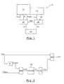
- a power unit 10 of a motor vehiclewhich comprises a motor 12 controlled by a method according to the teachings of the invention.
- the motor 12is coupled to a gearbox 14 with automated gear changes.
- the gearbox 14can be indifferently a conventional automatic transmission or a robotized gearbox.
- the motor 12is controlled by an electronic control unit 16 and the gearbox 14 is controlled by an electronic control unit 18.
- the engine 12is for example of the internal combustion type gasoline and it advantageously comprises a throttle inlet flap, or throttle body, of the motorized type, an injection device, and a device for igniting the fuel mixture which are electronically controlled by the steering unit 16.
- the control unit 16controls the load admitted into the cylinders of the engine 12 as a function of a torque setpoint motor C cm , and the engine then delivers a motor torque C m determined to the wheels of the vehicle.
- the driver of the vehicleacts on a device for controlling the acceleration of the vehicle, for example an accelerator pedal 20, which transmits to the control unit 16 information representative of the engine torque demand C m , or setpoint of driver torque C cc .
- the engine torque setpoint C cmis equivalent to the driver torque setpoint C cc .
- the electronic control unit 18 of the gearbox 14comprises a control algorithm which determines a transmission ratio setpoint C rt , for example according to laws of passage of the transmission ratio R t as a function of values. Mapped the vehicle speed with respect to a depression value of the accelerator pedal 20, which represents the Acc acceleration requested by the driver.
- control unit 16implements a transition strategy ST when it detects a request to change from an initial transmission ratio R ti to a new transmission ratio R tn less than the ratio initial R ti , the engine torque C m being substantially constant or rising.
- This requestwill be called "downshifting" RET in the following description.
- the control unit 16is for example informed of the downshift RET by the control unit 18.
- the transition strategy STconsists in determining, at regular time intervals ⁇ , from the driving torque set point C cc and from the maximum power P max available at the current rotation speed N of the motor 12, a limited torque setpoint C cl according to which the control unit 16 controls the load of the engine 12, so that the increase in the power transmitted to the wheels of the vehicle, or increase of the engine torque C m , is progressive between the initial transmission ratio R ti and the new transmission ratio R tn .
- the figure 2illustrates the operating principle of the transition strategy ST according to the invention at a given instant t, in order to determine the limited torque setpoint C cl .
- the transition strategy STbegins by converting the setpoint of the driving torque C cc into a power setpoint P cons demanded by the motor 12. For this it suffices to perform the product of the setpoint of the conductive torque C cc by the current rotation speed N of the engine 12, that is to say the rotation speed N of the engine 12 at time t.
- the transition strategy STdetermines an effective power P eff by choosing the lowest value between the power setpoint P cons and the maximum power P max available at the current rotation speed N of the engine 12.
- the effective power P effcorresponds to the power P m that would actually be demanded from the engine 12 if the transition strategy ST was not applied, the power P m requested to the motor 12 not being able to exceed the maximum power P max available.
- the transition strategy STdetermines a filtered power P wire by applying to the effective power P eff a filtering algorithm, or filter 22, which produces a progressive increase in the filtered power P wire over time.
- the filter 22must make it possible to obtain a profile for increasing the filtered power P wire that is more acceptable, ie more progressive, than the normal profile for increasing the effective power P eff in the absence of ST transition strategy.
- the letter "k”represents a constant which is fixed by design and the term P wire (t- ⁇ ) represents the filtered power P wire which has been calculated at time t- ⁇ , that is to say at the previous iteration.
- the transition strategy STconverts the filtered power P wire into a filtered pair C wire . For this it suffices to make the ratio of the filtered power P wire to the current rotation speed N of the motor 12.
- transition strategy STdetermines the limited torque setpoint C cl by choosing the lowest value between the conductive torque setpoint C cc and the filtered pair C wire .
- the transition strategy STis kept active during the entire duration of the downshift RET, that is to say until the control unit 16 detects the end of the downshift RET, and until the setpoint of driver torque Ccc is less than or equal to the limited torque setpoint Ccl.
- the end of retrograde RETis detected here when the control unit 18 indicates to the control unit 16 that the new transmission ratio R tn is engaged.
- the conductive torque setpoint C cccan become lower than or equal to the limited torque setpoint C c under the effect of the filter 22 or because of a decrease in the conductive torque setpoint C cc , for example when the driver wants to decrease the acceleration of the vehicle.
- the torque setpointsin particular the conductive torque setpoint C cc and the limited torque setpoint C cl , are replaced by associated power setpoints which are respectively obtained by making the product of each setpoint of torque given by the N associated rotation of the motor (12).
- control unit 16can control the motor 12 as a function of a conductive power setpoint at the instant t which is equal to the product of the conductive torque set point C cc at the instant t by the rotational speed N of the engine 12 at the instant t.
- a limited power setpointcan be calculated at time t by producing the product of the limited torque setpoint C cl at time t by the rotation speed N of the motor 12 at time t.
Landscapes
- Engineering & Computer Science (AREA)
- Chemical & Material Sciences (AREA)
- Combustion & Propulsion (AREA)
- Mechanical Engineering (AREA)
- Transportation (AREA)
- General Engineering & Computer Science (AREA)
- Automation & Control Theory (AREA)
- Control Of Transmission Device (AREA)
Description
Translated fromFrenchL'invention concerne un procédé de commande d'un groupe motopropulseur de véhicule automobile.The invention relates to a method for controlling a power unit of a motor vehicle.
L'invention concerne plus particulièrement un procédé de commande d'un groupe motopropulseur de véhicule automobile comportant un moteur, qui est commandé par une unité électronique de pilotage, et une boîte de vitesses à changements de rapports automatisés, qui est commandée par une unité électronique de commande, du type dans lequel l'unité de pilotage reçoit, de la part du conducteur et par l'intermédiaire d'un dispositif de commande de l'accélération, une information représentative de la demande de couple moteur, ou consigne de couple conducteur, en fonction de laquelle l'unité de pilotage est susceptible de piloter la charge du moteur, et du type dans lequel l'unité de pilotage, lorsqu'elle détecte une demande de passage d'un rapport initial de transmission à un nouveau rapport de transmission inférieur au rapport initial, le couple moteur étant sensiblement constant ou en hausse, met en oeuvre une stratégie de transition au cours de laquelle elle diminue le couple moteur.The invention more particularly relates to a control method of a powertrain of a motor vehicle comprising a motor, which is controlled by an electronic control unit, and an automated gearbox, which is controlled by an electronic unit. control device, of the type in which the control unit receives, from the driver and via an acceleration control device, information representative of the engine torque demand, or conductive torque setpoint , according to which the control unit is able to control the load of the engine, and the type in which the control unit, when it detects a request to change from an initial transmission ratio to a new ratio of transmission lower than the initial ratio, the engine torque being substantially constant or rising, implements a transition strategy during which it decreases the engine torque.
Sur les groupes motopropulseurs à transmission automatique, la pédale d'accélérateur permet au conducteur de commander à la fois le couple délivré par le moteur et le rapport de transmission engagé.On automatic transmission powertrains, the accelerator pedal allows the driver to control both the torque delivered by the engine and the engaged gear ratio.
Depuis de nombreuses années déjà, il existe des boîtes de vitesses à changements de rapports automatisés.For many years now, there have been automated gearbox transmissions.
Dans cette catégorie, on retrouve notamment les boîtes automatiques classiques dans lesquelles différents trains épicycloïdaux permettent de définir des rapports étagés prédéterminés, la sélection des rapports se faisant en actionnant différents freins ou embrayages qui permettent d'immobiliser sélectivement certains des composants du (ou des) train(s) épicycloïdal(aux) de manière à déterminer un rapport de vitesse entre l'arbre de sortie et l'arbre d'entrée de la boîte de vitesses.In this category, there are in particular conventional automatic boxes in which different planetary gear trains allow to define predetermined staggered ratios, the gear selection being done by actuating different brakes or clutches that can selectively immobilize some of the components of (or) train (s) epicyclic to determine a speed ratio between the output shaft and the input shaft of the gearbox.
Un autre type de boîte de vitesses à changements de rapports automatisés est constitué par les boîtes de vitesses mécaniques classiques, à crabots, dans lesquelles la sélection et l'engagement des rapports ne sont plus assurés directement par le conducteur au moyen d'un levier, mais par des vérins gérés par une unité de commande. Ces vérins peuvent n'intervenir qu'à la sollicitation expresse du conducteur, auquel cas ce dernier reste entièrement maître de l'instant du changement de rapport, ou au contraire de manière automatique, sous le contrôle de l'unité de commande de boîte, en fonction de paramètres analogues à ceux utilisés pour déterminer les instants de changement de rapport dans une boîte automatique classique.Another type of automatic gearbox transmission is constituted by conventional mechanical gearboxes, jaw, in which the selection and commitment of reports are no longer provided directly by the driver by means of a lever, but by jacks managed by a control unit. These jacks can intervene only at the express request of the driver, in which case the latter remains fully master of the moment of the gear change, or conversely automatically, under the control of the box control unit, according to parameters similar to those used to determine the times of change of ratio in a conventional automatic transmission.
Une telle boîte de vitesses sera appelée boîte de vitesses robotisée dans la suite du texte.Such a gearbox will be called robotic gearbox in the following text.
Généralement, l'unité de pilotage du moteur comporte un algorithme de commande du moteur qui détermine la consigne de couple moteur, par exemple suivant des valeurs cartographiées par rapport au régime moteur et à la valeur d'enfoncement de la pédale d'accélérateur.Generally, the engine control unit comprises an engine control algorithm which determines the engine torque setpoint, for example according to values mapped with respect to the engine speed and to the depression value of the accelerator pedal.
L'unité électronique de commande de la boîte de vitesses comporte un algorithme de commande qui détermine une consigne de rapport de transmission, par exemple suivant des lois de passage du rapport de transmission en fonction de valeurs cartographiées de la vitesse du véhicule par rapport à une valeur d'enfoncement de la pédale d'accélérateur.The electronic control unit of the gearbox comprises a control algorithm which determines a transmission ratio setpoint, for example according to laws of passage of the transmission ratio as a function of mapped values of the speed of the vehicle with respect to a transmission ratio. depression value of the accelerator pedal.
Dans le cas des boîtes de vitesses à rapports étagés et à changements automatisés, il est apparu qu'une très bonne maîtrise de la phase de changement de rapport était primordiale pour une conduite agréable du véhicule et pour le confort des passagers.In the case of gearboxes with staged ratios and automated changes, it appeared that a very good control of the shift phase was essential for a pleasant driving of the vehicle and for the comfort of the passengers.
Un tel agrément et un tel confort ne peuvent être obtenus qu'en supprimant complètement les à-coups susceptibles de survenir au cours du changement de rapport.Such approval and comfort can only be obtained by completely eliminating the jolts that may occur during the gear change.
Dans certaines conditions de fonctionnement du véhicule, par exemple lorsque le véhicule est dans une montée ou lorsque le conducteur enfonce la pédale d'accélérateur en vue d'effectuer un dépassement, l'algorithme de commande de la boîte de vitesses déclenche le passage d'un rapport de transmission inférieur de manière à provoquer une accélération du véhicule supérieure à celle obtenue sur le rapport initial.Under certain operating conditions of the vehicle, for example when the vehicle is in a climb or when the driver presses the accelerator pedal to overtake, the control algorithm of the gearbox triggers the passage of a lower transmission ratio so as to cause a vehicle acceleration higher than that obtained on the initial report.
Dans ce type de situation, le changement de rapport de transmission s'effectue alors que l'algorithme de commande du moteur demande quasiment le couple maximal disponible au moteur.In this type of situation, the transmission ratio change is made while the engine control algorithm requires almost the maximum torque available to the engine.
Ce couple maximal disponible est sensiblement équivalent pour chacun des deux régimes de rotation du moteur associés aux deux rapports de transmission, ou il peut être supérieur pour le régime de rotation associé au nouveau rapport de transmission, si le moteur était initialement dans un état de sous-régime.This maximum available torque is substantially equivalent for each of the two rotational speeds of the engine associated with the two transmission ratios, or it may be greater for the rotational speed associated with the new transmission ratio, if the engine was initially in a state of under -diet.
Par conséquent, le raccourcissement du rapport de démultiplication, alors que le couple moteur est sensiblement constant ou en hausse, provoque une augmentation brutale de l'accélération du véhicule.Therefore, the reduction of the gear ratio, while the engine torque is substantially constant or rising, causes a sharp increase in the acceleration of the vehicle.
Ce phénomène nuit au confort des utilisateurs du véhicule qui subissent des à-coups.This phenomenon is detrimental to the comfort of the vehicle users who experience jolts.
Il est déjà connu, lors du passage montant des rapports de transmission, de prévoir une stratégie de transition au cours de laquelle le moteur est piloté pour ne fournir qu'une partie seulement du couple demandé par le conducteur, par exemple en réduisant cette demande de couple d'un pourcentage fixe.It is already known, during the upward shift transmission reports, to provide a transition strategy during which the engine is controlled to provide only a portion of the torque requested by the driver, for example by reducing this demand for couple of a fixed percentage.
Ce type de stratégie ne s'applique pas lorsque la boîte de vitesse commande le passage d'un rapport de transmission inférieur au rapport initial.This type of strategy does not apply when the gearbox controls the passage of a transmission ratio lower than the initial gear.
Par la publication
L'invention vise à remédier à ces inconvénients en proposant un procédé de commande d'un groupe motopropulseur de véhicule automobile du type décrit précédemment, caractérisé en ce que la stratégie de transition consiste à déterminer, à intervalles de temps réguliers, à partir de la consigne de couple conducteur et à partir de la puissance maximale disponible au régime de rotation courant du moteur, une consigne de couple limité en fonction de laquelle l'unité de pilotage commande la charge du moteur, de manière que l'augmentation de la puissance transmise aux roues du véhicule soit progressive entre le rapport initial de transmission et le nouveau rapport de transmission.The invention aims to overcome these drawbacks by proposing a method for controlling a motor-vehicle powertrain of the type described above, characterized in that the transition strategy consists in determining, at regular time intervals, from the driver torque setpoint and from the maximum power available at the current rotation speed of the engine, a limited torque setpoint according to which the control unit controls the load of the engine, so that the increase in power transmitted the wheels of the vehicle is progressive between the initial transmission ratio and the new transmission ratio.
Selon d'autres caractéristiques de l'invention :
- la stratégie de transition consiste à effectuer, à intervalles de temps réguliers, les opérations suivantes :
- déterminer une puissance effective en choisissant la valeur la plus faible entre, d'une part, une consigne de puissance, qui est égale au produit de la consigne de couple conducteur par le régime de rotation courant du moteur et, d'autre part, la puissance maximale disponible au régime de rotation courant du moteur ;
- calculer une puissance filtrée en appliquant à la puissance effective un algorithme de filtrage qui produit une augmentation progressive de la puissance filtrée ;
- déterminer la consigne de couple limité en choisissant la valeur la plus faible entre la consigne de couple conducteur et le couple filtré, qui est égal à la puissance filtrée rapportée sur le régime de rotation courant du moteur ;
- l'unité de pilotage désactive la stratégie de transition lorsque les deux conditions suivantes sont remplies simultanément :
- l'unité de pilotage a détecté la fin du passage du rapport initial de transmission au nouveau rapport de transmission ;
- et la consigne de couple conducteur est inférieure ou égale au couple filtré ;
- on substitue aux consignes de couple des consignes de puissance associées qui sont obtenues respectivement en effectuant le produit de chaque consigne de couple par le régime de rotation associé du moteur.
- the transition strategy consists of performing, at regular time intervals, the following operations:
- determining an effective power by choosing the lowest value between, on the one hand, a power setpoint, which is equal to the product of the conductive torque setpoint by the current rotation speed of the engine and, on the other hand, the maximum available power at the current rotation speed of the engine;
- calculating a filtered power by applying to the effective power a filtering algorithm that produces a gradual increase in the filtered power;
- determining the limited torque setpoint by choosing the smallest value between the conductive torque setpoint and the filtered torque, which is equal to the filtered power reported on the current engine rotation speed;
- the control unit deactivates the transition strategy when both of the following conditions are fulfilled simultaneously:
- the control unit has detected the end of the transition from the initial transmission ratio to the new transmission ratio;
- and the conductive torque setpoint is less than or equal to the filtered torque;
- the torque setpoints are substituted with the associated power setpoints which are respectively obtained by performing the product of each torque setpoint by the associated rotational speed of the motor.
D'autres caractéristiques et avantages de l'invention apparaîtront à la lecture de la description détaillée qui suit pour la compréhension de laquelle on se reportera aux dessins annexés dans lesquels :
- la
figure 1 est un diagramme schématique qui représente un groupe motopropulseur commandé par un procédé conforme aux enseignements de l'invention ; - la
figure 2 est un diagramme schématique qui illustre le fonctionnement de la stratégie de transition du procédé de commande selon l'invention.
- the
figure 1 is a schematic diagram showing a powertrain controlled by a method according to the teachings of the invention; - the
figure 2 is a schematic diagram that illustrates the operation of the transition strategy of the control method according to the invention.
On a représenté schématiquement sur la
Le moteur 12 est accouplé à une boîte de vitesses 14 à changements de rapports automatisés.The
La boîte de vitesses 14 peut être indifféremment une boîte automatique classique ou une boîte de vitesses robotisée.The
Le moteur 12 est commandé par une unité électronique de pilotage 16 et la boîte de vitesses 14 est commandée par une unité électronique de commande 18.The
Le moteur 12 est par exemple du type à combustion interne à essence et il comporte avantageusement un volet d'admission des gaz, ou boîtier papillon, du type motorisé, un dispositif d'injection, et un dispositif d'allumage du mélange carburé qui sont commandés électroniquement par l'unité de pilotage 16.The
L'unité de pilotage 16 commande la charge admise dans les cylindres du moteur 12 en fonction d'une consigne de couple moteur Ccm, et le moteur délivre alors un couple moteur Cm déterminé aux roues du véhicule.The
Le conducteur du véhicule agit sur un dispositif de commande de l'accélération du véhicule, par exemple une pédale d'accélérateur 20, qui transmet à l'unité de pilotage 16 une information représentative de la demande de couple moteur Cm, ou consigne de couple conducteur Ccc.The driver of the vehicle acts on a device for controlling the acceleration of the vehicle, for example an
Dans ce cas, la consigne de couple moteur Ccm est équivalente à la consigne de couple conducteur Ccc.In this case, the engine torque setpoint Ccm is equivalent to the driver torque setpoint Ccc .
De manière classique, l'unité électronique de commande 18 de la boîte de vitesses 14 comporte un algorithme de commande qui détermine une consigne de rapport de transmission Crt, par exemple suivant des lois de passage du rapport de transmission Rt en fonction de valeurs cartographiées de la vitesse du véhicule par rapport à une valeur d'enfoncement de la pédale d'accélérateur 20, qui représente l'accélération Acc demandée par le conducteur.In a conventional manner, the
Conformément aux enseignements de l'invention, l'unité de pilotage 16 met en oeuvre une stratégie de transition ST lorsqu'elle détecte une demande de passage d'un rapport initial de transmission Rti à un nouveau rapport de transmission Rtn inférieur au rapport initial Rti, le couple moteur Cm étant sensiblement constant ou en hausse. Cette demande sera appelée « rétrogradage » RET dans la suite de la description.According to the teachings of the invention, the
L'unité de pilotage 16 est par exemple informée du rétrogradage RET par l'unité de commande 18.The
La stratégie de transition ST selon l'invention consiste à déterminer, à intervalles de temps τ réguliers, à partir de la consigne de couple conducteur Ccc et à partir de la puissance maximale Pmax disponible au régime de rotation courant N du moteur 12, une consigne de couple limité Ccl en fonction de laquelle l'unité de pilotage 16 commande la charge du moteur 12, de manière que l'augmentation de la puissance transmise aux roues du véhicule, ou augmentation du couple moteur Cm, soit progressive entre le rapport initial de transmission Rti et le nouveau rapport de transmission Rtn.The transition strategy ST according to the invention consists in determining, at regular time intervals τ, from the driving torque set point Ccc and from the maximum power Pmax available at the current rotation speed N of the
Lorsque la stratégie de transition ST est mise en oeuvre la consigne de couple moteur Ccm est alors équivalente à la consigne de couple limité Ccl.When the ST transition strategy is implemented the Ccm engine torque is then equivalent to the limited torque setpoint Ccl.
La
La stratégie de transition ST commence par convertir la consigne de couple conducteur Ccc en consigne de puissance Pcons demandée au moteur 12. Pour cela il suffit d'effectuer le produit de la consigne de couple conducteur Ccc par le régime de rotation courant N du moteur 12, c'est-à-dire le régime de rotation N du moteur 12 à l'instant t.The transition strategy ST begins by converting the setpoint of the driving torque Ccc into a power setpoint Pcons demanded by the
La stratégie de transition ST détermine ensuite une puissance effective Peff en choisissant la valeur la plus faible entre la consigne de puissance Pcons et la puissance maximale Pmax disponible au régime de rotation courant N du moteur 12.The transition strategy ST then determines an effective power Peff by choosing the lowest value between the power setpoint Pcons and the maximum power Pmax available at the current rotation speed N of the
On note que la puissance effective Peff correspond à la puissance Pm qui serait effectivement demandée au moteur 12 si l'on n'appliquait pas la stratégie de transition ST, la puissance Pm demandée au moteur 12 ne pouvant dépasser la puissance maximale Pmax disponible.It should be noted that the effective power Peff corresponds to the power Pm that would actually be demanded from the
La stratégie de transition ST détermine ensuite une puissance filtrée Pfil en appliquant à la puissance effective Peff un algorithme de filtrage, ou filtre 22, qui produit une augmentation progressive de la puissance filtrée Pfil au cours du temps.The transition strategy ST then determines a filtered power Pwire by applying to the effective power Peff a filtering algorithm, or filter 22, which produces a progressive increase in the filtered power Pwire over time.
Le filtre 22 doit permettre d'obtenir un profil d'augmentation de la puissance filtrée Pfil qui soit plus acceptable, c'est à dire plus progressif, que le profil normal d'augmentation de la puissance effective Peff en l'absence de stratégie de transition ST.The
Le filtre 22 est par exemple un filtre du premier ordre et l'équation de calcul de la puissance filtrée Pfil à un instant t donné peut s'exprimer de la manière suivante :
Dans cette équation, la lettre « k » représente une constante qui est fixée par conception et le terme Pfil(t-τ) représente la puissance filtrée Pfil qui a été calculée à l'instant t-τ, c'est à dire à l'itération précédente.In this equation, the letter "k" represents a constant which is fixed by design and the term Pwire (t-τ) represents the filtered power Pwire which has been calculated at time t-τ, that is to say at the previous iteration.
Puis la stratégie de transition ST convertit la puissance filtrée Pfil en couple filtré Cfil. Pour cela il suffit d'effectuer le rapport de la puissance filtrée Pfil sur le régime de rotation courant N du moteur 12.Then, the transition strategy ST converts the filtered power Pwire into a filtered pair Cwire . For this it suffices to make the ratio of the filtered power Pwire to the current rotation speed N of the
Enfin la stratégie de transition ST détermine la consigne de couple limité Ccl en choisissant la valeur la plus faible entre la consigne de couple conducteur Ccc et le couple filtré Cfil.Finally, the transition strategy ST determines the limited torque setpoint Ccl by choosing the lowest value between the conductive torque setpoint Ccc and the filtered pair Cwire .
Avantageusement, la stratégie de transition ST est maintenue active pendant toute la durée du rétrogradage RET, c'est à dire jusqu'à ce que l'unité de pilotage 16 détecte la fin du rétrogradage RET, et jusqu'à ce que la consigne de couple conducteur Ccc soit inférieure ou égale à la consigne de couple limité Ccl.Advantageously, the transition strategy ST is kept active during the entire duration of the downshift RET, that is to say until the
La fin du rétrogradage RET est détectée ici lorsque l'unité de commande 18 indique à l'unité de pilotage 16 que le nouveau rapport de transmission Rtn est engagé.The end of retrograde RET is detected here when the
On note que la consigne de couple conducteur Ccc peut devenir inférieure ou égale à la consigne de couple limité Ccl sous l'effet du filtre 22 ou en raison d'une baisse de la consigne de couple conducteur Ccc, par exemple lorsque le conducteur souhaite diminuer l'accélération du véhicule.It is noted that the conductive torque setpoint Ccc can become lower than or equal to the limited torque setpoint Cc under the effect of the
On a décrit ici un mode de réalisation dans lequel le moteur 12 est commandé par une consigne de couple moteur Ccm, mais bien entendu le procédé selon l'invention s'applique aussi à un moteur 12 commandé par une consigne de puissance.An embodiment has been described in which the
Dans ce cas les consignes de couple, notamment la consigne de couple conducteur Ccc et la consigne de couple limité Ccl, sont remplacées par des consignes de puissance associées qui sont obtenues respectivement en effectuant le produit de chaque consigne de couple donnée par le régime de rotation N associé du moteur (12).In this case, the torque setpoints, in particular the conductive torque setpoint Ccc and the limited torque setpoint Ccl , are replaced by associated power setpoints which are respectively obtained by making the product of each setpoint of torque given by the N associated rotation of the motor (12).
Ainsi, l'unité de pilotage 16 peut commander le moteur 12 en fonction d'une consigne de puissance conducteur à l'instant t qui est égale au produit de la consigne de couple conducteur Ccc à l'instant t par le régime de rotation N du moteur 12 à l'instant t.Thus, the
De manière similaire on peut calculer une consigne de puissance limitée à l'instant t en effectuant le produit de la consigne de couple limité Ccl à l'instant t par le régime de rotation N du moteur 12 à l'instant t.Similarly, a limited power setpoint can be calculated at time t by producing the product of the limited torque setpoint Ccl at time t by the rotation speed N of the
Claims (4)
- Method for controlling a drive train (10) of a motor vehicle comprising an engine (12), which is controlled by an electronic drive unit (16), and a gearbox (14), with automated gear changes (Rt), which is controlled by an electronic control unit (18), of the type in which the drive unit (16) receives, from the driver and via an acceleration control device (20), an item of information representing the engine torque requirement (Cm), or a drive torque setting (Ccc), according to which the drive unit (16) is capable of controlling the engine load (12), and of the type in which the drive unit (16), when it detects a requirement to switch from an initial transmission ratio (Rti) to a new transmission ratio (Rtn) that is below the initial ratio (Rti), the engine torque (Cm) being substantially constant or increased, applies a transition strategy (ST) during which it reduces the engine torque (Cm),
characterized in that the transition strategy (ST) consists in determining, at regular time intervals (τ), based on the drive torque setting (Ccc) and based on the maximum power (Pmax) available at the current rotation speed (N) of the engine (12), a limited torque setting (Ccl) according to which the drive unit (16) controls the engine load (12) so that the increase in power transmitted to the vehicle wheels is progressive between the initial transmission ratio (Rti) and the new transmission ratio (Rtn). - Control method according to the preceding claim,characterized in that the transition strategy (ST) consists in performing, at regular time intervals (τ), the following operations:- determining an effective power (Peff) by choosing the lowest value between, on the one hand, a power setting (Pcons), which is equal to the product of the drive torque setting (Ccc) by the current rotation speed (N) of the engine (12) and, on the other hand, the maximum power (Pmax) available at the current rotation speed (N) of the engine (12);- calculating a filtered power (Pfil) by applying to the effective power (Peff) a filtering algorithm which produces a progressive increase in the filtered power (Pfil) ;- determining the limited torque setting (Ccl) by choosing the lowest value between the drive torque setting (Ccc) and the filtered torque (Cfil), which is equal to the filtered power (Pfil) related to the current rotation speed (N) of the engine (12).
- Control method according to the preceding claim,characterized in that the drive unit (16) deactivates the transition strategy (ST) when the following two conditions are fulfilled simultaneously:- the drive unit (16) has detected the end of the switch from the initial transmission ratio (Rti) to the new transmission ratio (Rtn) ;- and the drive torque setting (Ccc) is below or equal to the filtered torque (Cfil).
- Control method according to any one of the preceding claims,characterized in that the user substitutes for the torque settings (Ccm, Ccc, Ccl) associated power settings which are obtained respectively by producing the product of each torque setting (Ccm, Ccc, Ccl) by the associated rotation speed (N) of the engine (12).
Applications Claiming Priority (2)
| Application Number | Priority Date | Filing Date | Title |
|---|---|---|---|
| FR0100512AFR2819455B1 (en) | 2001-01-16 | 2001-01-16 | METHOD OF CONTROLLING A DRIVE UNIT DURING CHANGES IN THE GEARS OF ITS AUTOMATIC TRANSMISSION |
| FR0100512 | 2001-01-16 |
Publications (2)
| Publication Number | Publication Date |
|---|---|
| EP1223070A1 EP1223070A1 (en) | 2002-07-17 |
| EP1223070B1true EP1223070B1 (en) | 2010-05-19 |
Family
ID=8858851
Family Applications (1)
| Application Number | Title | Priority Date | Filing Date |
|---|---|---|---|
| EP02290068AExpired - LifetimeEP1223070B1 (en) | 2001-01-16 | 2002-01-11 | Method for controlling a propulsion unit during gear shifts of an automatic transmission |
Country Status (3)
| Country | Link |
|---|---|
| EP (1) | EP1223070B1 (en) |
| DE (1) | DE60236388D1 (en) |
| FR (1) | FR2819455B1 (en) |
Families Citing this family (1)
| Publication number | Priority date | Publication date | Assignee | Title |
|---|---|---|---|---|
| JP4241077B2 (en) | 2003-02-14 | 2009-03-18 | トヨタ自動車株式会社 | Output control device for internal combustion engine |
Family Cites Families (4)
| Publication number | Priority date | Publication date | Assignee | Title |
|---|---|---|---|---|
| DE19611839A1 (en)* | 1996-03-26 | 1997-10-02 | Bosch Gmbh Robert | Method and device for controlling the torque output by a drive unit |
| DE19726194A1 (en)* | 1997-06-20 | 1998-12-24 | Bayerische Motoren Werke Ag | Method for influencing the torque of an internal combustion engine |
| DE19845157A1 (en)* | 1998-10-01 | 2000-04-06 | Zahnradfabrik Friedrichshafen | Controlling torque of motor vehicle IC engine with automatic gearbox so that continuous signals are exchanged between DME and electronic gearbox control across CAN data bus and engine torque also associated engine parameters |
| DE19950664A1 (en)* | 1999-10-21 | 2001-04-26 | Zahnradfabrik Friedrichshafen | Control of automatic gear box esp. stepped automatic drive for motor vehicle so that automatic gearbox is controlled by electronic gearbox control unit which constantly exchanges signals with digital engine electronic unit of IC engine |
- 2001
- 2001-01-16FRFR0100512Apatent/FR2819455B1/ennot_activeExpired - Fee Related
- 2002
- 2002-01-11DEDE60236388Tpatent/DE60236388D1/ennot_activeExpired - Lifetime
- 2002-01-11EPEP02290068Apatent/EP1223070B1/ennot_activeExpired - Lifetime
Also Published As
| Publication number | Publication date |
|---|---|
| FR2819455B1 (en) | 2003-04-11 |
| DE60236388D1 (en) | 2010-07-01 |
| FR2819455A1 (en) | 2002-07-19 |
| EP1223070A1 (en) | 2002-07-17 |
Similar Documents
| Publication | Publication Date | Title |
|---|---|---|
| EP1128977B1 (en) | Method for controlling engine torque when shifting gears | |
| FR2958613A1 (en) | METHOD FOR MANAGING A VEHICLE AND DEVICE FOR IMPLEMENTING IT | |
| FR2785860A1 (en) | METHOD AND DEVICE FOR CONTROLLING A MOTOR VEHICLE EQUIPPED WITH A GEARBOX | |
| JP2008014347A (en) | Vehicle driving force control device | |
| JPH11240358A (en) | Traveling behavior adaptive control method of automobile apparatus which can be variably set | |
| JP5257508B2 (en) | Drive source control apparatus and control method | |
| JP2009508041A (en) | Method and apparatus for controlling engine torque and speed | |
| JP5185954B2 (en) | How to operate an automatic or semi-automatic transmission of a large vehicle in idling mode | |
| EP1223070B1 (en) | Method for controlling a propulsion unit during gear shifts of an automatic transmission | |
| EP3292032B1 (en) | Method for managing preventive approval gradients during deceleration | |
| EP2780206B1 (en) | Function for controlling the speed of a motor vehicle on a slope | |
| EP3287672A1 (en) | Method for controlling an engine torque of a vehicle, in particular of a motor vehicle | |
| FR2846606A1 (en) | Method for regulating vehicle speed comprises reducing actual speed by changing down gearbox rather than controlling brake control | |
| FR2869575A1 (en) | METHOD AND DEVICE FOR LIMITING THE SPEED OF A VEHICLE | |
| EP1310401B1 (en) | Method for downshifting an automatised gearbox | |
| FR2818936A1 (en) | METHOD FOR IMPLEMENTING A TRANSMISSION OF A MOTOR VEHICLE AND INSTALLATION FOR CARRYING OUT THE METHOD | |
| EP1791715B1 (en) | Method for multi-operating mode control of an automated transmission for a motor vehicle, in particular for idle speed running with activated brake and corresponding device | |
| WO2006085023A1 (en) | Method for control of the reversal of power in a system comprising a torque converter and mechanical unit encompassing said method | |
| WO2012035220A1 (en) | Method for changing gears up for an automatic gearbox of a motor vehicle | |
| EP1293376B1 (en) | Strategy for early clutch reengagement while shifting up automatised gearboxes | |
| FR2802482A1 (en) | METHOD FOR REGULATING A STARTING PROCESS FOR MOTOR VEHICLES | |
| FR2783587A1 (en) | METHOD AND DEVICE FOR A RETROGRADATION OPERATION OF A MOTOR VEHICLE GEARBOX | |
| EP3221760B1 (en) | Method for controlling the torque of a power train comprising a thermal motor | |
| EP2529129B1 (en) | Method for controlling an engine and an electronic clutch during a first phase of gear ratio changing in a mechanical gearbox | |
| WO2004072458A1 (en) | Control method and device for the propulsion motor unit of a motor vehicle driven by an internal combustion engine |
Legal Events
| Date | Code | Title | Description |
|---|---|---|---|
| PUAI | Public reference made under article 153(3) epc to a published international application that has entered the european phase | Free format text:ORIGINAL CODE: 0009012 | |
| AK | Designated contracting states | Kind code of ref document:A1 Designated state(s):AT BE CH CY DE DK ES FI FR GB GR IE IT LI LU MC NL PT SE TR | |
| AX | Request for extension of the european patent | Free format text:AL;LT;LV;MK;RO;SI | |
| RAP1 | Party data changed (applicant data changed or rights of an application transferred) | Owner name:RENAULT S.A.S. | |
| AKX | Designation fees paid | ||
| 17P | Request for examination filed | Effective date:20030103 | |
| RBV | Designated contracting states (corrected) | Designated state(s):BE DE ES | |
| REG | Reference to a national code | Ref country code:DE Ref legal event code:8566 | |
| 17Q | First examination report despatched | Effective date:20070817 | |
| GRAP | Despatch of communication of intention to grant a patent | Free format text:ORIGINAL CODE: EPIDOSNIGR1 | |
| RIC1 | Information provided on ipc code assigned before grant | Ipc:B60W 30/18 20060101ALI20090930BHEP Ipc:B60W 10/06 20060101ALN20090930BHEP Ipc:F16H 63/50 20060101AFI20090930BHEP Ipc:F16H 61/04 20060101ALN20090930BHEP Ipc:B60W 10/10 20060101ALN20090930BHEP Ipc:F16H 59/20 20060101ALN20090930BHEP | |
| GRAS | Grant fee paid | Free format text:ORIGINAL CODE: EPIDOSNIGR3 | |
| GRAA | (expected) grant | Free format text:ORIGINAL CODE: 0009210 | |
| AK | Designated contracting states | Kind code of ref document:B1 Designated state(s):BE DE ES | |
| REF | Corresponds to: | Ref document number:60236388 Country of ref document:DE Date of ref document:20100701 Kind code of ref document:P | |
| PG25 | Lapsed in a contracting state [announced via postgrant information from national office to epo] | Ref country code:ES Free format text:LAPSE BECAUSE OF FAILURE TO SUBMIT A TRANSLATION OF THE DESCRIPTION OR TO PAY THE FEE WITHIN THE PRESCRIBED TIME-LIMIT Effective date:20100830 | |
| PLBE | No opposition filed within time limit | Free format text:ORIGINAL CODE: 0009261 | |
| STAA | Information on the status of an ep patent application or granted ep patent | Free format text:STATUS: NO OPPOSITION FILED WITHIN TIME LIMIT | |
| 26N | No opposition filed | Effective date:20110222 | |
| REG | Reference to a national code | Ref country code:DE Ref legal event code:R097 Ref document number:60236388 Country of ref document:DE Effective date:20110221 | |
| PGFP | Annual fee paid to national office [announced via postgrant information from national office to epo] | Ref country code:BE Payment date:20160120 Year of fee payment:15 | |
| PGFP | Annual fee paid to national office [announced via postgrant information from national office to epo] | Ref country code:DE Payment date:20170120 Year of fee payment:16 | |
| PG25 | Lapsed in a contracting state [announced via postgrant information from national office to epo] | Ref country code:BE Free format text:LAPSE BECAUSE OF NON-PAYMENT OF DUE FEES Effective date:20170131 | |
| REG | Reference to a national code | Ref country code:BE Ref legal event code:MM Effective date:20170131 | |
| REG | Reference to a national code | Ref country code:DE Ref legal event code:R119 Ref document number:60236388 Country of ref document:DE | |
| PG25 | Lapsed in a contracting state [announced via postgrant information from national office to epo] | Ref country code:DE Free format text:LAPSE BECAUSE OF NON-PAYMENT OF DUE FEES Effective date:20180801 |