EP1223002B1 - Holding device for holding large structures - Google Patents
Holding device for holding large structuresDownload PDFInfo
- Publication number
- EP1223002B1 EP1223002B1EP01126849AEP01126849AEP1223002B1EP 1223002 B1EP1223002 B1EP 1223002B1EP 01126849 AEP01126849 AEP 01126849AEP 01126849 AEP01126849 AEP 01126849AEP 1223002 B1EP1223002 B1EP 1223002B1
- Authority
- EP
- European Patent Office
- Prior art keywords
- clamping
- component
- holding apparatus
- units
- machine
- Prior art date
- Legal status (The legal status is an assumption and is not a legal conclusion. Google has not performed a legal analysis and makes no representation as to the accuracy of the status listed.)
- Expired - Lifetime
Links
- 238000012545processingMethods0.000claimsabstractdescription24
- 238000000034methodMethods0.000claimsabstractdescription18
- 238000007667floatingMethods0.000claimsdescription3
- 238000006073displacement reactionMethods0.000claims1
- 230000008569processEffects0.000abstractdescription11
- 238000003754machiningMethods0.000description9
- 238000004519manufacturing processMethods0.000description3
- 230000001419dependent effectEffects0.000description2
- 238000005516engineering processMethods0.000description2
- 238000007789sealingMethods0.000description2
- 230000006978adaptationEffects0.000description1
- 230000008859changeEffects0.000description1
- 238000010276constructionMethods0.000description1
- 230000008878couplingEffects0.000description1
- 238000010168coupling processMethods0.000description1
- 238000005859coupling reactionMethods0.000description1
- 238000013461designMethods0.000description1
- 238000011161developmentMethods0.000description1
- 230000018109developmental processEffects0.000description1
- 230000000694effectsEffects0.000description1
- 230000006872improvementEffects0.000description1
- 238000005304joiningMethods0.000description1
- 238000012544monitoring processMethods0.000description1
- 210000004258portal systemAnatomy0.000description1
- 238000001228spectrumMethods0.000description1
- 239000000725suspensionSubstances0.000description1
- 230000008961swellingEffects0.000description1
- 230000001360synchronised effectEffects0.000description1
- 238000012549trainingMethods0.000description1
- 238000012546transferMethods0.000description1
Images


Classifications
- B—PERFORMING OPERATIONS; TRANSPORTING
- B21—MECHANICAL METAL-WORKING WITHOUT ESSENTIALLY REMOVING MATERIAL; PUNCHING METAL
- B21J—FORGING; HAMMERING; PRESSING METAL; RIVETING; FORGE FURNACES
- B21J15/00—Riveting
- B21J15/10—Riveting machines
- B21J15/14—Riveting machines specially adapted for riveting specific articles, e.g. brake lining machines
- B21J15/142—Aerospace structures
- B—PERFORMING OPERATIONS; TRANSPORTING
- B21—MECHANICAL METAL-WORKING WITHOUT ESSENTIALLY REMOVING MATERIAL; PUNCHING METAL
- B21J—FORGING; HAMMERING; PRESSING METAL; RIVETING; FORGE FURNACES
- B21J15/00—Riveting
- B21J15/10—Riveting machines
- B21J15/14—Riveting machines specially adapted for riveting specific articles, e.g. brake lining machines
- B—PERFORMING OPERATIONS; TRANSPORTING
- B23—MACHINE TOOLS; METAL-WORKING NOT OTHERWISE PROVIDED FOR
- B23Q—DETAILS, COMPONENTS, OR ACCESSORIES FOR MACHINE TOOLS, e.g. ARRANGEMENTS FOR COPYING OR CONTROLLING; MACHINE TOOLS IN GENERAL CHARACTERISED BY THE CONSTRUCTION OF PARTICULAR DETAILS OR COMPONENTS; COMBINATIONS OR ASSOCIATIONS OF METAL-WORKING MACHINES, NOT DIRECTED TO A PARTICULAR RESULT
- B23Q1/00—Members which are comprised in the general build-up of a form of machine, particularly relatively large fixed members
- B23Q1/03—Stationary work or tool supports
- B23Q1/037—Stationary work or tool supports comprising series of support elements whose relative distance is adjustable
- B—PERFORMING OPERATIONS; TRANSPORTING
- B23—MACHINE TOOLS; METAL-WORKING NOT OTHERWISE PROVIDED FOR
- B23Q—DETAILS, COMPONENTS, OR ACCESSORIES FOR MACHINE TOOLS, e.g. ARRANGEMENTS FOR COPYING OR CONTROLLING; MACHINE TOOLS IN GENERAL CHARACTERISED BY THE CONSTRUCTION OF PARTICULAR DETAILS OR COMPONENTS; COMBINATIONS OR ASSOCIATIONS OF METAL-WORKING MACHINES, NOT DIRECTED TO A PARTICULAR RESULT
- B23Q3/00—Devices holding, supporting, or positioning work or tools, of a kind normally removable from the machine
- B23Q3/16—Devices holding, supporting, or positioning work or tools, of a kind normally removable from the machine controlled in conjunction with the operation of the tool
- B—PERFORMING OPERATIONS; TRANSPORTING
- B23—MACHINE TOOLS; METAL-WORKING NOT OTHERWISE PROVIDED FOR
- B23Q—DETAILS, COMPONENTS, OR ACCESSORIES FOR MACHINE TOOLS, e.g. ARRANGEMENTS FOR COPYING OR CONTROLLING; MACHINE TOOLS IN GENERAL CHARACTERISED BY THE CONSTRUCTION OF PARTICULAR DETAILS OR COMPONENTS; COMBINATIONS OR ASSOCIATIONS OF METAL-WORKING MACHINES, NOT DIRECTED TO A PARTICULAR RESULT
- B23Q7/00—Arrangements for handling work specially combined with or arranged in, or specially adapted for use in connection with, machine tools, e.g. for conveying, loading, positioning, discharging, sorting
- B23Q7/04—Arrangements for handling work specially combined with or arranged in, or specially adapted for use in connection with, machine tools, e.g. for conveying, loading, positioning, discharging, sorting by means of grippers
- B23Q7/048—Multiple gripper units
- Y—GENERAL TAGGING OF NEW TECHNOLOGICAL DEVELOPMENTS; GENERAL TAGGING OF CROSS-SECTIONAL TECHNOLOGIES SPANNING OVER SEVERAL SECTIONS OF THE IPC; TECHNICAL SUBJECTS COVERED BY FORMER USPC CROSS-REFERENCE ART COLLECTIONS [XRACs] AND DIGESTS
- Y10—TECHNICAL SUBJECTS COVERED BY FORMER USPC
- Y10T—TECHNICAL SUBJECTS COVERED BY FORMER US CLASSIFICATION
- Y10T29/00—Metal working
- Y10T29/49—Method of mechanical manufacture
- Y10T29/49826—Assembling or joining
- Y10T29/49895—Associating parts by use of aligning means [e.g., use of a drift pin or a "fixture"]
- Y10T29/49899—Associating parts by use of aligning means [e.g., use of a drift pin or a "fixture"] by multiple cooperating aligning means
- Y—GENERAL TAGGING OF NEW TECHNOLOGICAL DEVELOPMENTS; GENERAL TAGGING OF CROSS-SECTIONAL TECHNOLOGIES SPANNING OVER SEVERAL SECTIONS OF THE IPC; TECHNICAL SUBJECTS COVERED BY FORMER USPC CROSS-REFERENCE ART COLLECTIONS [XRACs] AND DIGESTS
- Y10—TECHNICAL SUBJECTS COVERED BY FORMER USPC
- Y10T—TECHNICAL SUBJECTS COVERED BY FORMER US CLASSIFICATION
- Y10T29/00—Metal working
- Y10T29/49—Method of mechanical manufacture
- Y10T29/49826—Assembling or joining
- Y10T29/49895—Associating parts by use of aligning means [e.g., use of a drift pin or a "fixture"]
- Y10T29/49902—Associating parts by use of aligning means [e.g., use of a drift pin or a "fixture"] by manipulating aligning means
- Y—GENERAL TAGGING OF NEW TECHNOLOGICAL DEVELOPMENTS; GENERAL TAGGING OF CROSS-SECTIONAL TECHNOLOGIES SPANNING OVER SEVERAL SECTIONS OF THE IPC; TECHNICAL SUBJECTS COVERED BY FORMER USPC CROSS-REFERENCE ART COLLECTIONS [XRACs] AND DIGESTS
- Y10—TECHNICAL SUBJECTS COVERED BY FORMER USPC
- Y10T—TECHNICAL SUBJECTS COVERED BY FORMER US CLASSIFICATION
- Y10T29/00—Metal working
- Y10T29/53—Means to assemble or disassemble
- Y10T29/53961—Means to assemble or disassemble with work-holder for assembly
- Y—GENERAL TAGGING OF NEW TECHNOLOGICAL DEVELOPMENTS; GENERAL TAGGING OF CROSS-SECTIONAL TECHNOLOGIES SPANNING OVER SEVERAL SECTIONS OF THE IPC; TECHNICAL SUBJECTS COVERED BY FORMER USPC CROSS-REFERENCE ART COLLECTIONS [XRACs] AND DIGESTS
- Y10—TECHNICAL SUBJECTS COVERED BY FORMER USPC
- Y10T—TECHNICAL SUBJECTS COVERED BY FORMER US CLASSIFICATION
- Y10T29/00—Metal working
- Y10T29/53—Means to assemble or disassemble
- Y10T29/53978—Means to assemble or disassemble including means to relatively position plural work parts
Definitions
- the inventionrelates to a holding device for holding large format Components, wherein the holding device is designed as a flexible clamping system and has several clamping units.
- the inventionfurther relates to a Processing machine with such a holding device, a method for Upgrading and holding large-sized components, including component processing with a processing machine with an upper and a lower tool done with a holding device for holding large-sized components in There is an operative connection and a method for loading the holding device.
- This Documentshows a machine for holding components made up of several units consists, with each unit having movable arches on rails and several Arches are provided for receiving one or more large-format components.
- the two outer arches of such a support unitare fixed to the rails connected and the entire carrier unit is ready for set-up with a loading crane implemented.
- One component fixed on the carrier unit or several so clamped Componentsare inserted into a riveting machine via another rail system pushed in and the unit is fixed in a fixed position.
- the affected archescan be transferred to another Position.
- the inventionis therefore based on the object of a device for holding training large-sized components, the effort for the plant technology by dispensing with rigid support systems with geometry-specific devices reduced and flexible clamping of workpieces of different shapes and Size should be achieved.
- a processing machine that can be coupled to a patented holding deviceis specified in claim 20.
- a method for processing a large-sized component and a method for loading the holding device with a large-sized componentare specified in claims 21 and 22.
- the holding device 10is flexible Clamping system formed, which several - eight in the embodiment shown - Has clamping units 1 to 8.
- the clamping units 1 to 8are on one Rail system 11 arranged and can according to the application be positioned flexibly.
- the rail system 11is preferably on the floor attached to a production hall and moving the clamping units 1 to 8 on the Rails 11 is in the main direction of travel, i.e.
- the outer clamping units 1 and 8are designed as clamping bridges 12 and 13, wherein the clamping bridge 12 the front and the tension bridge 13 form the rear tension bridge.
- the clamping bridges 12 and 13are supported on both sides by support columns 15.
- the inner ones Clamping units 2 to 7each consist of individual clamping arms 14, each are positioned on a support column 15.
- the main details of the clamping units 1 to 8are shown in more detail in FIGS. 4 to 11.
- a processing machine 16 with an upper tool 17 and a lower tool 18can be seen in FIG. 2.
- the processing machine 16is designed as an automatic orbital riveting machine with a working space of up to approximately 120 ° and can be moved on a rail system 11A in the machine main direction, which runs parallel to the rail system 11.
- the upper tool 18is arranged on a semicircular arc 19, the arc ends of which are supported in the rail system 11A.
- the sheet 19has guides, the upper tool 17 being movable along these guides for the machining operations.
- the lower tool 18is positioned within the arc 19, preferably in the area of the center of the circle of the arc 19.
- the upper and lower tools 17 and 18cooperate for a riveting process at a predetermined riveting point. Positioning at the riveting point and control of the sequence of a riveting process take place via program controls, ie NC programs, which thereby implement largely automated riveting. At the same time, a coupling to the control of the clamping system is possible in order to recognize interference contours in good time and to move the corresponding clamping arms 14 out of the working area of the riveting machine 16.
- the control computeris arranged in a computing station 20, from which monitoring and control activities of a worker can also be carried out manually via a control panel.
- the clamping units 1 to 8are designed in such a way that a predetermined number of these units can be moved out of the working area of the machine 16 in order to make room for the machine 16 to perform its working cycle in the area of a holder, ie in the area of the clamping arm 14, while the greatest possible number of clamping units simultaneously supports the workpiece.
- the processing machine 16can drive over the clamping units 1 to 8 with the upper tool 17, the lower tool 18 can move past the supporting columns 15 of the clamping units 1 to 8.
- the clamping units 1 to 8 of the clamping systemare arranged in such a way that there are two rows of working zones / mounting zones running parallel to the main direction of travel of the machine.
- Fig. 3the holding device 10 with the clamping units 1 to 8 in one Front and top view.
- the arrangement of the clamping units 1 to 8 to each other and the position of a component 21 in a tensioned positionis good recognizable.
- the tension bridge 12is in relation to the rail system 11 or 11A fixed and forms a reference point for comparing the coordinates with the Processing machine 16.
- the clamping bridges 12 and 13fix and clamp this Component 21 on the face.
- the clamping arms 14fix the component 21 via brackets 22, in the embodiment shown by means of suction.
- each holding zone of the holding systemthere is a clamping unit with a clamping arm 14 (except at the front and rear end of a component, since clamping bridges 12 and 13 are provided here), one or more individual holders 22 per clamping arm 14 (see, for example, suction unit 28 in FIG. 9) are arranged.
- Each clamping arm 14is arranged on a column 15 which can be moved parallel to the main machine direction.
- each workpiece holdercan be released from the support of the component 21 in each work zone independently of other clamping arms 14 and can be inserted into the support column 15, so that the arm 14 no longer projects into the working area of the machine 16.
- the individual holders 22 on each clamping arm 14can be moved along the arm and have workpiece support elements 23 which can be moved in height (see suction head 281 in FIG. 9).
- the middle support columns 152 to 157 attached between the end columns, ie the support columns 151 and 158 of the outer clamping units 1 and 8,can be moved out of the working area of the machine past the column 151 via the rail system 11.
- the number of clamping units 2 to 7 usedcan thus be made variable and is dependent on the size of the component 21 to be carried, its rigidity and shape and the machining forces acting on the component 21. With such flexible clamping units 1 to 8, it is easy to convert to different component sizes and to dispense with type-specific and thus geometry-specific devices.
- FIG. 4shows the tension bridge 12, which has a support arch 121 which is supported on both sides between the support columns 151 and 151 '.
- the clamping bridge 12can be fixed on the hall floor in order to obtain a reference point for the component coordinates and the tool coordinates.
- the fixingis carried out by fixing the support columns 151 and 151 '.
- the support arch 121can be displaced along the columns 151 and 151 ', that is to say the support arch 121 can be raised and lowered in the z direction, for example, in order to simplify loading processes or to allow a different working height of the machine.
- the upper position of the support arch 121 shownmust be assumed (machining position).
- the dashed position indicatedindicates the loading position.
- a plurality of clamping units 24 and a fixing unit 25are arranged on the support arch 121.
- the fixing unit 25is provided in order to achieve a first positioning and alignment in the x-y direction when the component 21 is placed on the holding device 10 at a fixed point of the large-area component 21.
- a pin 255is positioned in a receiving bore (not shown) of the component 21.
- the component 21is clamped on the end face by means of the clamping units 24.
- the clamping units 24can be positioned along a guide track 26 on the support arch 121.
- An adjustment of the respective clamping or fixing head 241 or 251is provided in order to reach every possible coordinate point in the specified component clamping area 27.
- the details of the individual components clamping unit 24 and fixing unit 25are shown in FIGS. 7 and 8.
- FIGS. 7 and 8show the tension bridge 13, which is between the support columns 158 and 158 ' has a support arch 131 which is supported on both sides.
- the support arch 131can be moved in the z direction in order to simplify loading processes (loading position shown in dashed lines) or a working height of the machine allow, which allows a passage of the lower tool 18 (Machining position). This movement can be done alone or in sync with the others Clamping arms 14 or the clamping bridge 12 take place, preferably a computer-aided process for moving the clamping units and the Clamping arms 14 and the clamping bridges 12 and 13 must take place.
- On the support arch 131a plurality of clamping units 24 and a fixing unit 25 are arranged, the Operation corresponds to the clamping unit 24 and the fixing unit 25 am Support arch 121. Further details can be found in FIGS. 7 and 8.
- FIG. 6shows an inner clamping unit 2, 3, 4, 5, 6 or 7 (hereinafter 3), each of which has a clamping arm 14 and a column 15.
- the clamping unit 3is shown in a view from above, a view from the front and in side views.
- the loading position - left illustration in FIG. 6 (with the tension arm 14 pivoted up) and the parking position - right illustration in FIG. 6are shown in a side view.
- the tensioning arm 14can be moved along the column 15 in the z direction.
- all of the mounting arms 14 or the tensioning bridges 12 and 13can be raised or lowered alone or synchronously with one another in order to provide an ergonomic loading height or, on the other hand, an optimal working height for the machine enable.
- the clamping arm 14is connected to the column 15 via a support element 32, which enables a further movement of the clamping arm 14 in the y direction and a pivoting movement about a pivot axis 33. With these possibilities of movement, the swivel arm 14 can be completely folded in, for example when not in use (in the park position), or by swiveling up about the swivel axis 33 to assume an almost upright position (loading position) for receiving a component.
- the tensioning arms 14 of a row of brackets (mounting zone) of the tensioning systemare erected synchronously by rotation about the pivot axes 33, and loading with a vertically supplied component is made possible. Since in the embodiment shown the component is regularly taken up from one side, the clamping arms 143, 145 and 147 of a row of brackets are each provided with arm extensions which can be extended telescopically in order to support the component over a larger width beyond its center. Furthermore, loading receptacles 30 and 31 are provided on the tensioning arms 143, 145 and 147 in addition to the telescopic arm 29.
- the telescopic arm 29can be moved out of the head of the clamping arm 14 in accordance with the component size, and the inner loading receptacle 30 is provided in the head region of the telescopic arm 29 for supporting the component 21.
- the inner loading receptacle 30is designed as a support point (component support).
- the lower outer edge of the component 21is fixed on the outer loading receptacle 31. Further details of the outer loading receptacle 31 are set out in FIG. 11.
- the outer loading receptacle 31is arranged on the clamping arm 14 in a rack guide 34 and can be flexibly positioned according to the size of the component 21 to be accommodated.
- the loading receptacles 30 and 31can be preset manually, by motor or by NC component programming in accordance with the component size, component geometry and desired component position on the mounting system.
- the tensioning arms 143, 145 and 147 and their telescopic arm extensionsBy means of the tensioning arms 143, 145 and 147 and their telescopic arm extensions, the vertically supplied component can be held solely by the holding device 10 without the component transport means to be guided.
- the componentcan be pivoted from the vertical loading position into the horizontal machining position by rotation about the pivot axis 33 of the holding arms 14. In this position, the component is supported by means of the individual brackets, which are designed as suction units 28 in the embodiment shown. Details of the suction units 28 are shown in FIGS. 9 and 10.
- each clamping arm 14with telescopic extensions and / or loading receptacles. Then, for example, with a component that is narrower than half the working width of the machine, it can be loaded onto a longitudinal half of the mounting device 10, while the other half of the mounting device 10 can accommodate another correspondingly narrow component.
- FIGS. 7 to 11show the clamping unit 24 in three views, which can be positioned on a curved guide 26A of the clamping bridge 12 or 13 (see FIGS. 4 or 5) via a rack and pinion drive.
- the clamping head 241 of the clamping unit 24is arranged on a base body 242, which is the carrier for the necessary components for the drive and the necessary control lines.
- An actuator 243 designed as a spindle driveis provided, which enables the head to be adjusted in the z direction.
- a further actuating movement of the clamping head 241 in the x directionis achieved with an actuator 244.
- a pneumatic cylinder 245is provided to pivot the clamping head 241 and to perform a stroke to generate the clamping force.
- the fixing unit 25shows the fixing unit 25 in three views.
- the positioning of the Fixing unit 25 on the tensioning bridge 12 or 13takes place via the curved guide 26B, which is preferably designed as a rack guide.
- the fixing unit 25has a base body 252, on which the fixing head 251 is arranged.
- a pin 255is provided on the fixing head 251, which plugs into a Receiving hole of the component 21 can be inserted and thus the component fixed.
- the fixing head 251itself is in two directions over NC axes swiveling in order to be able to optimally adapt to the component contour.
- the suction unit 28can be seen, which forms the preferred individual holder 22.
- the suction unit 28consists of a base body 282 on which a suction head 281 is adapted as the workpiece support element 23.
- the suction unit 28can be moved and positioned along the clamping arm 14 via a rack and pinion drive 34 (see also FIG. 6).
- An actuating movement in the z directiontakes place by means of an actuator 283.
- Compressed aircan be supplied to the suction head 281 via an air line 284 in order to be able to position the component on the holding device 10 in a “floating” manner.
- the suction head 281can be seen in an enlarged representation, which is connected to the base body 282 by means of an adapter.
- the suction head 281has a spherical cap 286 and sealing lips 287 to achieve an airtight seal between the suction head 281 and the component.
- a receiving unitcan be provided which, instead of a suction head 281, has workpiece support points or other holding elements in a known manner.
- the outer loading receptacle 31is shown in detail in FIG. 11.
- the loading head 311On one Base body 312, the loading head 311 is arranged.
- the loading head 311can over an actuator 313 can be adjusted in height and is gimbaled:
- the Loading receptacle 31is in a rack guide 34 along the tension arm 14 positionable. The positioning depends on the component size.
- jaws 314are provided, which the component 21 according to Hold the positioning on a support edge 315.
- a loading and positioning process of a large component on the Flexible holding device 10can proceed as follows: The large-area component is lifted vertically using a suspension crane Holding device 10 supplied.
- the 30 with loading receptacles and 31provided tension arms 143, 145, 147 of a support zone swung.
- On the outer loading receptacles 31is on a support edge 315 placed on the outer edge of component 21.
- the on the extended tension arm (Telescopic arm) 29 arranged inner loading receptacle 30supports the component in one Area beyond the center of the component. At this point the crane system can deposit and detach the component.
- the componentis now held completely from the bracket series of the clamping units 143, 145, 147.
- the tensioning arms 143, 145 and 147are swung down the clamping position, with the opposite clamping arms 142, 144 and 146 of the other bracket zone are already positioned in this position and after Reaching the end position of the swivel arm supports the component 21 via the entire component area.
- the componentis made by means of the suction units 28 "Floating" held and for positioning on the tension bridge 12 and on the Clamping bridge 13 are in the mounting holes of the component pin 255 respective fixing unit 25 inserted. After fixing the pins 255 this will be Component clamped on the face and clamped by means of the suction units 28.
- a predetermined number of Clamping units 2 to 7can use their clamping arms 14 from the work area Drive out machine 16 to machine 16 for the purpose of their Work cycle in the area of a bracket, d. H. 14 place in the area of the clamping arm to make while maximum number of clamping units at the same time the workpiece continues to be supported. All movements of the clamping units as well their components are coordinated and enabled by NC controls on the one hand a synchronous movement of the individual clamping devices and also a Movement of a single clamping device largely automated.
Landscapes
- Engineering & Computer Science (AREA)
- Mechanical Engineering (AREA)
- Jigs For Machine Tools (AREA)
- Automatic Assembly (AREA)
- Chain Conveyers (AREA)
Abstract
Description
Translated fromGermanDie Erfindung betrifft eine Halteeinrichtung zum Halten von großformatigenBauteilen, wobei die Halteeinrichtung als flexibles Spannsystem ausgebildet ist undmehrere Spanneinheiten aufweist. Die Erfindung betrifft weiterhin eineBearbeitungsmaschine mit einer solchen Halteeinrichtung, ein Verfahren zumAufrüsten und Halten von großformatigen Bauteilen, wobei eine Bauteilbearbeitungmit einer Bearbeitungsmaschine mit einem oberen und einem unteren Werkzeugerfolgt, die mit einer Halteeinrichtung zum Halten von großformatigen Bauteilen inWirkverbindung steht und ein Verfahren zum Beladen der Halteeinrichtung.The invention relates to a holding device for holding large formatComponents, wherein the holding device is designed as a flexible clamping system andhas several clamping units. The invention further relates to aProcessing machine with such a holding device, a method forUpgrading and holding large-sized components, including component processingwith a processing machine with an upper and a lower tooldone with a holding device for holding large-sized components inThere is an operative connection and a method for loading the holding device.
Es sind flexible Spannsysteme beispielsweise aus DE 197 45 145 A 1 bekannt. DiesesDokument zeigt eine Maschine zum Halten von Bauteilen, die aus mehreren Einheitenbesteht, wobei jede Einheit auf Schienen verfahrbare Bögen aufweist und mehrereBögen zur Aufnahme eines oder mehrerer großformatiger Bauteile vorgesehen sind.Die beiden äußeren Bögen einer derartigen Trägereinheit sind fest mit den Schienenverbunden und die gesamte Trägereinheit ist für Rüstvorgänge mit einem Ladekranumsetzbar. Ein auf der Trägereinheit fixiertes Bauteil bzw. mehrere so gespannteBauteile werden über ein weiteres Schienensystem in eine Nietmaschinehineingeschoben und die Einheit wird in einer festen Position fixiert. Um während desNietvorganges eine Kollision zwischen Elementen der Nietmaschine und Elementen des Haltesystems zu vermeiden, können die betroffenen Bögen an eine anderePosition verlagert werden. Das wird realisiert, indem die Teleskopstangenzurückgezogen werden und der betroffende Bogen auf den Schienen verfahren wird.Während dieser Zeit ruht der Nietprozess. Auch ist im gesamten Bereich des freigewordenen Bogens die Unterstützung bzw. Fixierung des Bauteils aufgehoben. Nachdem Nietvorgang wird der gesamte Bauteilträger aus der Nietmaschineherausgeschoben und es können weitere Arbeiten am Bauteil vorgenommen werdenbzw. der Bauteilträger wird umgesetzt und das Bauteil wird von der Trägereinheitabgerüstet.Flexible clamping systems are known, for example, from DE 197 45 145 A1. ThisDocument shows a machine for holding components made up of several unitsconsists, with each unit having movable arches on rails and severalArches are provided for receiving one or more large-format components.The two outer arches of such a support unit are fixed to the railsconnected and the entire carrier unit is ready for set-up with a loading craneimplemented. One component fixed on the carrier unit or several so clampedComponents are inserted into a riveting machine via another rail systempushed in and the unit is fixed in a fixed position. To during theRiveting a collision between elements of the riveting machine and elementsTo avoid the holding system, the affected arches can be transferred to anotherPosition. That is realized by the telescopic poleswithdrawn and the sheet concerned is moved on the rails.The riveting process stops during this time. The entire area is also freedisengaged arch the support or fixation of the component. ToThe riveting process turns the entire component carrier out of the riveting machinepushed out and further work can be carried out on the componentor the component carrier is implemented and the component is from the carrier unitdisarmed.
Bekannte Lösungen bauen somit auf anlagentechnisch vorhandene Trägersystemewie Wechsel- und/oder Positionierrahmen, Vorrichtungsgerüste, Fügestationen,Portalsysteme, Rüsttischsysteme auf. Zum Teil müssen die Rüst- undPositioniervorgänge nach komplexen technischen und zeitlichen Regelungenabgewickelt werden. Darüber hinaus sind hohe Investitionen in der Anlagentechniknotwendig, insbesondere wenn ein großes Bauteilspektrum mit unterschiedlichenAbmessungen und Formen abzudecken ist. Die Anlagenbeschickung erfolgtüblicherweise durch den Einsatz weiterer Subsysteme wie Bühnenkonstruktionen,Transferwagen, Hubbühnen, Förderkörbe u.a., wobei aufgrund der Abmessungen (fürHautfelder eines Flugzeugrumpfes ungefähr bis Größe 11 x 3 m) und möglichenKrümmungen der zu fügenden großformatigen Bauteile ein hoher logistischerAufwand betrieben werden muss.Known solutions build on existing carrier systemssuch as change and / or positioning frames, jig scaffolding, joining stations,Portal systems, setup table systems. In part, the setup andPositioning processes according to complex technical and time regulationsbe handled. In addition, there are high investments in plant technologynecessary, especially if a large range of components with differentDimensions and shapes to be covered. The system is loadedusually through the use of further subsystems such as stage constructions,Transfer trolleys, lifting platforms, conveyor baskets, etc., due to the dimensions (forSkin areas of an aircraft fuselage approximately up to size 11 x 3 m) and possibleCurvatures of the large-format components to be joined are highly logisticalEffort must be operated.
Der Erfindung liegt daher die Aufgabe zugrunde, eine Vorrichtung zum Halten vongroßformatigen Bauteilen auszubilden, wobei der Aufwand für die Anlagentechnikdurch Verzicht auf starre Trägersysteme mit geometriebestimmten Vorrichtungenverringert und ein flexibles Spannen von Werkstücken unterschiedlicher Form undGröße erreicht werden soll.The invention is therefore based on the object of a device for holdingtraining large-sized components, the effort for the plant technologyby dispensing with rigid support systems with geometry-specific devicesreduced and flexible clamping of workpieces of different shapes andSize should be achieved.
Diese Aufgabe wird bei einer gattungsgemäßen Halteeinrichtung mit den im Patentanspruch1 genannten Maßnahmen gelöst.This object is achieved in a generic holding device with the in claim1 measures resolved.
Weiterbildungen und vorteilhafte Ausgestaltungen sind in den Unteransprüchen 2 bis19 angegeben sowie in der nachfolgenden Beschreibung dargestellt.Further developments and advantageous refinements are in the
Eine Bearbeitungsmaschine, die mit einer patentgemäßen Halteeinrichtung koppelbarist, ist im Patentanspruch 20 angegeben.
Ein Verfahren zum Bearbeiten eines großformatigen Bauteils sowie ein Verfahren zumBeladen der Halteeinrichtung mit einem großformatigen Bauteil sind in denAnsprüchen 21 und 22 angegeben.A processing machine that can be coupled to a patented holding device is specified in
A method for processing a large-sized component and a method for loading the holding device with a large-sized component are specified in
Mit der erfindungsgemäßen Vorrichtung wird ermöglicht, dass flexibel aufunterschiedliche Anforderungen im Fertigungsprozess (Umstellung auf andereBauteilabmessungen u. a.) reagiert werden kann und eine Verminderung der Rüstzeitermöglicht wird. Weiterhin sind folgende Vorteile zu erreichen:
- Verzicht auf Trägersysteme
- Vermeidung des Einsatzes von Subsystemen
- Verbesserung der Ergonomie bei Rüstvorgängen
- Erhöhung der Flexibilität des Spannsystems, d.h. Turmlösung,Einsatz von weiteren möglichen Hilfsachsen, Abdeckung vonBauteilspektren mit größtmöglichen Abmessungen (sphärisch,Anschwellung)
- No support systems
- Avoiding the use of subsystems
- Improvement of ergonomics during setup processes
- Increasing the flexibility of the clamping system, ie tower solution, use of further possible auxiliary axes, covering component spectra with the largest possible dimensions (spherical, swelling)
In der Zeichnung ist ein Ausführungsbeispiel der Erfindung dargestellt, welches nachstehendanhand der Figuren 1 bis 11 näher beschrieben wird.In the drawing, an embodiment of the invention is shown, which followsis described in more detail with reference to Figures 1 to 11.
Es zeigt:
- Fig. 1
- eine perspektivische Darstellung der erfindungsgemäßen Halteeinrichtung,
- Fig. 2
- die Halteeinrichtung gemäß Fig. 1 in Wirkverbindung mit einerBearbeitungsmaschine,
- Fig. 3
- die Halteeinrichtung in einer Zwei-Seiten-Ansicht,
- Fig. 4
- eine erste Spanneinheit als vorderer Teil der Halteeinrichtung,
- Fig. 5
- eine achte Spanneinheit als letzter Teil der Halteeinrichtung,
- Fig. 6
- eine Spanneinheit als Einzelheit aus dem mittleren Teil der Halteeinrichtung,
- Fig. 7
- eine Klemmeinheit als Bestandteil einer Spanneinheit,
- Fig. 8
- eine Fixiereinheit als Bestandteil einer Spanneinheit,
- Fig. 9
- eine äußere Saugeinheit als Bestandteil einer Spanneinheit,
- Fig. 10
- eine schwenkbare Saugeinheit als Bestandteil einer Spanneinheit und
- Fig. 11
- eine äußere Beladeaufnahme als Bestandteil einer Spanneinheit.
- Fig. 1
- a perspective view of the holding device according to the invention,
- Fig. 2
- 1 in operative connection with a processing machine,
- Fig. 3
- the holding device in a two-sided view,
- Fig. 4
- a first clamping unit as the front part of the holding device,
- Fig. 5
- an eighth clamping unit as the last part of the holding device,
- Fig. 6
- a clamping unit as a detail from the middle part of the holding device,
- Fig. 7
- a clamping unit as part of a clamping unit,
- Fig. 8
- a fixing unit as part of a clamping unit,
- Fig. 9
- an external suction unit as part of a clamping unit,
- Fig. 10
- a swiveling suction unit as part of a clamping unit and
- Fig. 11
- an outer loading receptacle as part of a clamping unit.
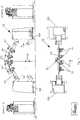
In der Fig. 1 ist eine erfindungsgemäße Halteeinrichtung 10 zum Halten vongroßformatigen Bauteilen gezeigt, vorzugsweise von gekrümmten Hautblechen, diezur Herstellung von Hautfeldern für Rumpfschalen eines Flugzeuges zur Anwendungkommen. Die zu fertigenden Hautfelder können Abmessungen bis ungefähr 11m x3m aufweisen. An zylindrisch gekrümmten bzw. sphärisch gekrümmten Bauteilensind längsverlaufende Stringer anzufügen. Die Halteeinrichtung 10 ist als flexiblesSpannsystem ausgebildet, welches mehrere - in der gezeigten Ausführungsform acht- Spanneinheiten 1 bis 8 aufweist. Die Spanneinheiten 1 bis 8 sind auf einemSchienensystem 11 angeordnet und können entsprechend dem Anwendungsfallflexibel positioniert werden. Das Schienensystem 11 ist vorzugsweise am Bodeneiner Fertigungshalle befestigt und das Verlagern der Spanneinheiten 1 bis 8 auf denSchienen 11 ist in Hauptverfahrrichtung, d.h. in x-Richtung entsprechend des in dieFigur eingezeichneten Koordinatensystems möglich. Die äußeren Spanneinheiten 1und 8 sind als Spannbrücken 12 und 13 ausgebildet, wobei die Spannbrücke 12 die vordere und die Spannbrücke 13 die hintere Spannbrücke bilden. Die Spannbrücken12 und 13 werden beidseitig von Tragsäulen 15 abgestützt. Die innerenSpanneinheiten 2 bis 7 bestehen jeweils aus einzelnen Spannarmen 14, die jeweilsan einer Tragsäule 15 positioniert sind. Die wesentlichen Details der Spanneinheiten1 bis 8 sind in den Figuren 4 bis 11 genauer dargestellt.1 shows a holding
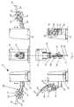
In der Fig. 2 ist eine Bearbeitungsmaschine 16 mit einem oberen Werkzeug 17 undeinem unteren Werkzeug 18 ersichtlich. Sie ist in der gezeigten Ausführung mit dererfindungsgemäßen Halteeinrichtung 10 gekoppelt, um großflächige Bauteilevorzugsweise zylindrisch oder sphärisch gekrümmte Hautfelder einerFlugzeugrumpfschale zu bearbeiten. Die Bearbeitungsmaschine 16 ist in dergezeigten Ausführung als automatische Orbitalnietmaschine mit einem Arbeitsraumbis ungefähr 120° ausgebildet und kann auf einem Schienensystem 11A inMaschinenhauptrichtung verfahren werden, welches parallel zum Schienensystem 11verläuft. Das obere Werkzeug 18 ist an einem halbkreisförmigen Bogen 19angeordnet, deren Bogenenden in dem Schienensystem 11A gelagert sind. DerBogen 19 weist Führungen auf, wobei das obere Werkzeug 17 für dieBearbeitungsvorgänge entlang dieser Führungen verfahrbar ist. Das untere Werkzeug18 ist innerhalb des Bogens 19, vorzugsweise im Bereich des Kreismittelpunktes desBogens 19, positioniert. Das obere und das untere Werkzeug 17 und 18 wirken füreinen Nietvorgang an einer vorgegebenen Nietstelle zusammen. Eine Positionierungan der Nietstelle und eine Steuerung des Ablaufs eines Nietvorganges erfolgen überProgrammsteuerungen, d.h. NC-Programme die damit eine weitgehendautomatisierte Nietfertigung realisieren. Gleichzeitig ist eine Kopplung mit derSteuerung des Spannsystems möglich, um rechtzeitig Störkonturen zu erkennen unddie entsprechenden Spannarme 14 aus dem Arbeitsbereich der Nietmaschine 16herauszufahren. Der Steuerungscomputer ist in einer Rechenstation 20 angeordnet,von der aus auch Überwachungs- und Steuerungstätigkeiten eines Werkers über einBedienpult manuell vorgenommen werden können.
Die Spanneinheiten 1 bis 8 sind derartig ausgeführt, dass eine vorbestimmte Anzahldieser Einheiten aus dem Arbeitsbereich der Maschine 16 herausgefahren werden kann, um der Maschine 16 für die Verrichtung ihres Arbeitszyklus im Bereich einerHalterung, d. h. im Bereich des Spannarmes 14 Platz zu machen, während einegrößtmögliche Anzahl von Spanneinheiten gleichzeitig das Werkstück weiterhinunterstützt.
Die Bearbeitungsmaschine 16 kann mit dem oberen Werkzeug 17 die Spanneinheiten1 bis 8 überfahren, das untere Werkzeug 18 kann seitlich an den Tragsäulen 15 derSpanneinheiten 1 bis 8 vorbeifahren. Die Spanneinheiten 1 bis 8 des Spannsystemssind so angeordnet sind, dass sich zwei parallel zur Hauptverfahrrichtung derMaschine verlaufende Reihen von Arbeitszonen/Halterungszonen ergeben.A processing
The clamping units 1 to 8 are designed in such a way that a predetermined number of these units can be moved out of the working area of the
The processing
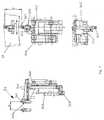
In der Fig. 3 ist die Halteeinrichtung 10 mit den Spanneinheiten 1 bis 8 in einerAnsicht von vorn und von oben dargestellt. Die Anordnung der Spanneinheiten 1 bis8 zueinander sowie die Lage eines Bauteils 21 in gespannter Position ist guterkennbar. Die Spannbrücke 12 ist in Relation zum Schienensystem 11 bzw. 11Afest fixiert und bildet einen Referenzpunkt zum Abgleich der Koordinaten mit derBearbeitungsmaschine 16. Die Spannbrücken 12 und 13 fixieren und klemmen dasBauteil 21 stirnseitig. Die Spannarme 14 fixieren das Bauteil 21 über Halterungen 22,in dem gezeigten Ausführungsbeispiel mittels Saugkraft.In Fig. 3, the holding
Aus den Figuren 1 bis 3 ist erkennbar, dass die Spanneinheiten 1 bis 8 desHaltesystems 10 so angeordnet sind, dass der gesamte Raum und insbesondere derHallenboden unterhalb der Spanneinheiten 1 bis 8 beim Bearbeitungsvorgang freizugänglich ist und dass in der Mitte zwischen den beiden Halterungsreihen ein füreinen Werker möglichst aufrecht begehbarer Raum vorhanden ist.
In jeder Halterungszone des Haltesystems befindet sich eine Spanneinheit mit einemSpannarm 14 (ausgenommen am vorderen und hinteren Ende eines Bauteils, da hierSpannbrücken 12 und 13 vorgesehen sind), wobei je Spannarm 14 eine odermehrere Einzelhalterungen 22 (siehe beispielsweise Saugeinheit 28 in Fig. 9)angeordnet sind. Jeder Spannarm 14 ist an einer parallel zurMaschinenhauptrichtung verfahrbaren Säule 15 angeordnet.
Der Arm 14 jeder Werkstückhalterung kann in jeder Arbeitszone unabhängig von anderen Spannarmen 14 aus der Unterstützung des Bauteiles 21 herausgelöst und indie Tragsäule 15 eingefahren werden kann, so dass der Arm 14 nicht mehr in denArbeitsbereich der Maschine 16 hineinragt. Die Einzelhalterungen 22 auf jedemSpannarm 14 sind längs des Arms verfahrbar und weisen in der Höhe verfahrbareWerkstücktragelemente 23 (siehe Saugkopf 281 in Fig. 9) auf. Die zwischen denEndsäulen, d.h. den Tragsäulen 151 und 158 der äußeren Spanneinheiten 1 und 8angebrachten mittleren Tragsäulen 152 bis 157 können über das Schienensystem 11an der Säule 151 vorbei aus dem Arbeitsbereich der Maschine herausgefahrenwerden. Somit kann die Anzahl der benutzten Spanneinheiten 2 bis 7 variabelgestaltet werden und ist abhängig von der Größe des zu tragenden Bauteils 21, derenSteifigkeit und Form und den auf das Bauteil 21 wirkenden Bearbeitungskräften. Mitderartig flexiblen Spanneinheiten 1 bis 8 kann unaufwendig eine Umrüstung aufunterschiedliche Bauteilgrößen und ein Verzicht auf typ- und damitgeometriebestimmte Vorrichtungen erfolgen.It can be seen from FIGS. 1 to 3 that the clamping units 1 to 8 of the holding
In each holding zone of the holding system there is a clamping unit with a clamping arm 14 (except at the front and rear end of a component, since clamping
The
In den Figuren 4 und 5 sind die Spannbrücken 12 und 13 jeweils alsDetaildarstellung ersichtlich. Es sind jeweils alle vier Ansichten gezeigt. Fig. 4 zeigtdie Spannbrücke 12, die zwischen den Tragsäulen 151 und 151' einen sich beidseitigabstützenden Stützbogen 121 aufweist. Die Spannbrücke 12 ist am Hallenbodenfixierbar, um damit einen Referenzpunkt für die Bauteilkoordinaten und dieWerkzeugkoordinaten zu erhalten. Das Festlegen erfolgt über das Fixieren derTragsäulen 151 und 151'. Der Stützbogen 121 ist entlang der Säulen 151 und 151'verschiebbar, d.h. in z - Richtung kann beispielsweise ein Hoch- und Herunterfahrendes Stützbogens 121 erfolgen, um Beladevorgänge zu vereinfachen oder eine andereArbeitshöhe der Maschine zu ermöglichen. Um den Zugang des unteren Werkzeugs18 während des Bearbeitungsvorganges zu ermöglichen, ist die gezeigte oberePosition des Stützbogens 121 einzunehmen (Bearbeitungsposition). Die angedeutetegestrichelte Position zeigt die Beladeposition an. Am Stützbogen 121 sind mehrereKlemmeinheiten 24 sowie eine Fixiereinheit 25 angeordnet. Die Fixiereinheit 25 istvorgesehen, um beim Auflegen des Bauteils 21 auf die Halteeinrichtung 10 an einemFixpunkt des größflächigen Bauteils 21 eine erste Positionierung und Ausrichtung in x - y Richtung zu erreichen. In eine Aufnahmebohrung (nicht gezeigt) des Bauteils 21wird zu diesem Zweck ein Abstecker 255 positioniert. Mittels der Klemmeinheiten 24wird das Bauteil 21 stirnseitig geklemmt. Die Klemmeinheiten 24 sind entlang einerFührungsbahn 26 am Stützbogen 121 positionierbar. Eine Verstellung des jeweiligenKlemm- bzw. Fixierkopfes 241 bzw. 251 ist vorgesehen, um im angegebenenBauteilspannbereich 27 jeden möglichen Koordinatenpunkt zu erreichen.
Die Details der Einzelkomponenten Klemmeinheit 24 und Fixiereinheit 25 sind in denFign. 7 und 8 gezeigt.In Figures 4 and 5, the clamping bridges 12 and 13 are each shown as a detailed representation. All four views are shown. FIG. 4 shows the
The details of the individual
Die Fig. 5 zeigt die Spannbrücke 13, die zwischen den Tragsäulen 158 und 158'einen sich beidseitig abstützenden Stützbogen 131 aufweist. Der Stützbogen 131kann in z - Richtung verfahren werden, um Beladevorgänge zu vereinfachen(gestrichelt dargestellte Beladeposition) oder eine Arbeitshöhe der Maschine zuermöglichen, die ein Durchfahren des unteren Werkzeuges 18 ermöglicht(Bearbeitungsposition). Diese Bewegung kann allein oder synchron mit den weiterenSpannarmen 14 bzw. der Spannbrücke 12 erfolgen, wobei vorzugsweise eincomputerunterstützter Ablauf zur Bewegung der Spanneinheiten sowie derSpannarme 14 und der Spannbrücken 12 und 13 zu erfolgen hat. Am Stützbogen131 sind mehrere Klemmeinheiten 24 sowie eine Fixiereinheit 25 angeordnet, derenFunktionsweise entspricht den Klemmeinheit 24 und der Fixiereinheit 25 amStützbogen 121. Nähere Details sind in den Fign. 7 und 8 dargestellt.5 shows the
In Fig. 6 ist eine innere Spanneinheit 2, 3, 4, 5, 6 oder 7 (im folgenden 3)ersichtlich, die jeweils einen Spannarm 14 sowie eine Säule 15 aufweist. DieSpanneinheit 3 ist in einer Ansicht von oben, einer Ansicht von vorn und inSeitenansichten dargestellt. Neben der Arbeitsposition ist in je einer Seitenansichtdie Beladeposition - linke Darstellung in Figur 6 - (mit hochgeschwenktem Spannarm14) und die Parkposition - rechte Darstellung in Fig. 6 - gezeigt. In denSeitenansichten ist ersichtlich, dass der Spannarm 14 in z-Richtung entlang derSäule 15 verfahren werden kann. Wie schon bei den Spannbrücken 12 und 13erläutert, können alle Halterungsarme 14 bzw. die Spannbrücken 12 und 13 allein oder synchron miteinander in der Höhe herauf- oder heruntergefahren werden, umeine ergonomische Beladehöhe zu ergeben bzw. andererseits eine für die Maschineoptimale Arbeitshöhe zu ermöglichen. Die Anbindung des Spannarmes 14 an derSäule 15 erfolgt über ein Tragelement 32, welches eine weitere Bewegung desSpannarmes 14 in y-Richtung sowie eine Schwenkbewegung um eine Schwenkachse33 ermöglicht. Mit diesen Bewegungsmöglichkeiten kann der Schwenkarm 14 völligeingeklappt werden, beispielsweise bei Nichtgebrauch (in Parkposition), oder durchHochschwenken um die Schwenkachse 33 eine nahezu aufrechte Position(Beladeposition) zur Aufnahme eines Bauteils einnehmen. Zum Beladen werden dieSpannarme 14 einer Halterungsreihe (Halterungszone) des Spannsystems(Spannarme 143, 145, 147- siehe Fig. 3) durch Drehung um die Schwenkachsen 33synchron aufrecht gestellt und ein Beladen mit einem vertikal zugeführten Bauteil istermöglicht. Da in der gezeigten Ausführung eine Aufnahme des Bauteils regelmäßigvon einer Seite erfolgt, werden die Spannarme 143, 145 und 147 einerHalterungsreihe mit jeweils Armverlängerungen versehen, die teleskopischausgefahren werden können, um das Bauteil auf größerer Breite über seine Mittehinaus zu unterstützen. Weiterhin sind an den Spannarmen 143, 145 und 147 nebendem Teleskoparm 29 jeweils Beladeaufnahmen 30 und 31 vorgesehen. DerTeleskoparm 29 ist entsprechend der Bauteilgröße aus dem Kopf des Spannarmes14 herausfahrbar und im Kopfbereich des Teleskoparmes 29 ist die innereBeladeaufnahme 30 zum Abstützen des Bauteils 21 vorgesehen. Die innereBeladeaufnahme 30 ist als Auflagepunkt (Bauteilauflage) ausgebildet. An der äußerenBeladeaufnahme 31 wird die untere Außenkante des Bauteils 21 fixiert. NähereEinzelheiten zur äußeren Beladeaufnahme 31 werden in der Fig. 11 dargelegt. Dieäußere Beladeaufnahme 31 ist am Spannarm 14 in einer Zahnstangenführung 34angeordnet und kann entsprechend der Größe des aufzunehmenden Bauteils 21flexibel positioniert werden. Die Beladeaufnahmen 30 und 31 können manuell,motorisch oder durch NC-Bauteilprogrammierung entsprechend der Bauteilgröße,Bauteilgeometrie und gewünschter Bauteillage auf dem Halterungssystemvoreingestellt werden.
Mittels der Spannarme 143, 145 und 147 und deren teleskopischen Armverlängerungen kann das vertikal zugeführte Bauteil allein durch dieHalteeinrichtung 10 ohne das zu führende Bauteiltransportmittel gehalten werden.Durch Drehung um die Schwenkachse 33 der Halterungsarme 14 kann das Bauteilvon der vertikalen Beladeposition in die horizontale Bearbeitungsposition geschwenktwerden. In dieser Position erfolgt eine Stützung des Bauteils mittels derEinzelhalterungen, die in der gezeigten Ausführung als Saugeinheiten 28 ausgebildetsind. Details zu den Saugeinheiten 28 sind den Fign. 9 und 10 zu entnehmen. DieAusführung der Spannarme 143, 145 und 147 mit Teleskoparmen 29 sowie mitBeladeaufnahmen 30 und 31 in nur einer Halterungsreihe der Halteeinrichtung 10 istbauteilbedingt. In weiteren Ausführungsformen der Erfindung ist es möglich, jedenSpannarm 14 mit teleskopischen Verlängerungen und/oder Beladeaufnahmenvorzusehen. Dann kann beispielsweise bei einem schmaleren als der halbenArbeitsbreite der Maschine entsprechenden Bauteil dieses auf einer Längshälfte derHalterungseinrichtung 10 geladen werden, während die andere Hälfte derHalterungseinrichtung 10 ein anderes entsprechend schmales Bauteil aufnehmenkann.6 shows an
By means of the tensioning
Die wichtigen Komponenten der Spanneinheiten 1 bis 8, wie Klemmeinheiten,Fixiereinheiten, Saugeinheiten und Beladeaufnahmen sind als Einzelheiten in denFiguren 7 bis 11 gezeigt.
In Fig. 7 ist die Klemmeinheit 24 in drei Ansichten ersichtlich, die an einerBogenführung 26A der Spannbrücke 12 bzw. 13 (siehe Fign. 4 oder 5) über einenZahnstangenantrieb positionierbar ist. Der Klemmkopf 241 der Klemmeinheit 24 istan einem Grundkörper 242 angeordnet, der Träger für die notwendigenKomponenten zum Antrieb sowie der notwendigen Steuerleitungen ist. So ist ein alsSpindelantrieb ausgebildeter Stellantrieb 243 vorgesehen, der eine Verstellung desKopfes in z-Richtung ermöglicht. Eine weitere Stellbewegung des Klemmkopfes 241in x-Richtung ist mit einem Stellantrieb 244 erreicht. Ein Pneumatikzylinder 245 istvorgesehen, um den Klemmkopf 241 zu schwenken und einen Hub zur Erzeugung derKlemmkraft auszuführen.The important components of the clamping units 1 to 8, such as clamping units, fixing units, suction units and loading receptacles, are shown as details in FIGS. 7 to 11.
7 shows the clamping
In Fig. 8 ist die Fixiereinheit 25 in drei Ansichten dargestellt. Die Positionierung derFixiereinheit 25 an der Spannbrücke 12 bzw. 13 erfolgt über die Bogenführung 26B,die vorzugsweise als Zahnstangenführung ausgebildet ist. Die Fixiereinheit 25 weisteinen Grundkörper 252 auf, an dem über einen Auslegearm 254 der Fixierkopf 251angeordnet ist. Am Fixierkopf 251 ist ein Abstecker 255 vorgesehen, der in eineAufnahmebohrung des Bauteils 21 eingeführt werden kann und somit das Bauteilfixiert. Um einen Bauteilspannbereich 27 zu erreichen, ist neben der Stellbewegungin y-Richtung eine Stellbewegung in z-Richtung mittels einem Stellantrieb 253vorgesehen. Der Fixierkopf 251 selbst ist in zwei Richtungen über NC-Achsenschwenkbar, um sich optimal der Bauteilkontur anpassen zu können.8 shows the fixing
In den Fign. 9 und 10 ist die Saugeinheit 28 ersichtlich, die die bevorzugteEinzelhalterung 22 bildet. Die Saugeinheit 28 besteht aus einem Grundkörper 282,an dem als Werkstücktragelement 23 ein Saugkopf 281 adaptiert ist. Über einenZahnstangenantrieb 34 ist die Saugeinheit 28 entlang des Spannarms 14 bewegbarund positionierbar (siehe auch Fig. 6). Eine Stellbewegung in z-Richtung erfolgtmittels eines Stellantriebs 283. Über eine Luftleitung 284 kann dem Saugkopf 281Druckluft zugeführt werden, um "schwimmend" das Bauteil auf der Halteeinrichtung10 positionieren zu können. Für die Spannfunktion wird mittels eines Ejektors 285Unterdruck erzeugt, der am Saugkopf 281 die zum Halten des Bauteils notwendigeSaugkraft zur Verfügung stellt. In Fig. 10 ist in einer vergrößerten Darstellung derSaugkopf 281 ersichtlich, der mittels eines Adapters mit dem Grundkörper 282verbunden ist. Zur optimalen Anpassung an die zylindrische oder sphärischeKrümmung des Bauteils 21 weist der Saugkopf 281 eine Kugelkalotte 286 sowieDichtlippen 287 zum Erreichen einer luftdichten Abdichtung zwischen Saugkopf 281und Bauteil auf.
In einer weiteren Ausgestaltung der Erfindung kann alternativ zur Saugeinheit 28 eineAufnahmeeinheit vorgesehen werden, die statt eines Saugkopfes 281Werkstückauflagepunkte oder andere Halteelemente nach bekannter Art aufweist.In Figs. 9 and 10, the
In a further embodiment of the invention, as an alternative to the
In Fig. 11 ist die äußere Beladeaufnahme 31 in Einzelheiten gezeigt. An einemGrundkörper 312 ist der Beladekopf 311 angeordnet. Der Beladekopf 311 kann übereinen Stellantrieb 313 in der Höhe verstellt werden und ist kardanisch gelagert: DieBeladeaufnahme 31 ist in einer Zahnstangenführung 34 entlang des Spannarms 14positionierbar. Die Positionierung erfolgt in Abhängigkeit von der Bauteilgröße. AmBeladekopf 311 sind Klemmbacken 314 vorgesehen, die das Bauteil 21 nach derPositionierung an einer Auflagekante 315 festhalten.The
Ein Belade- und Positioniervorgang eines großflächigen Bauteils auf dieerfindungsgemäße flexible Halteeinrichtung 10 kann folgendermaßen ablaufen:Das großflächige Bauteil wird in vertikaler Ausrichtung mittels eines Hängekrans derHalteeinrichtung 10 zugeführt. Zum Beladevorgang sind die mit Beladeaufnahmen 30und 31 versehenen Spannarme 143, 145, 147 einer Halterungszonehochgeschwenkt. An den äußeren Beladeaufnahmen 31 wird an einer Auflagekante315 die Außenkante des Bauteils 21 aufgesetzt. Die am verlängerten Spannarm(Teleskoparm) 29 angeordnete innere Beladeaufnahme 30 stützt das Bauteil in einemBereich über die Bauteilmitte hinaus ab. Zu diesem Zeitpunkt kann die Krananlagedas Bauteil absetzen und lösen. Die Halterung des Bauteils erfolgt nunmehrvollständig von der Halterungsreihe der Spanneinheiten 143, 145, 147. Aus derBeladeposition erfolgt ein Herunterschwenken der Spannarme 143, 145 und 147 indie Spannposition, wobei die gegenüberliegenden Spannarme 142, 144 und 146 deranderen Halterungszone bereits in dieser Position positioniert sind und nachErreichen der Endposition des Schwenkarmes ein Abstützen des Bauteils 21 über diegesamte Bauteilfläche erfolgt. Mittels der Saugeinheiten 28 wird das Bauteil"schwimmend" gehalten und zur Positionierung an der Spannbrücke 12 sowie an derSpannbrücke 13 werden in Aufnahmebohrungen des Bauteils Abstecker 255 derjeweiligen Fixiereinheit 25 gesteckt. Nach dem Fixieren der Abstecker 255 wird dasBauteil stirnseitig geklemmt und mittels der Saugeinheiten 28 gespannt. Um eineZugänglichkeit des unteren Werkzeugs 18 zu den Bearbeitungsstellen zuermöglichen, werden die Spannbrücken 12 und 13 sowie die Spannarme 14synchron in Arbeitsposition (in z-Richtung) verfahren. Der eigentliche Bearbeitungsvorgang, d.h. das Nieten von Bauteilen, ist bereits in derFigurenbeschreibung zur Fig. 2 erläutert. Eine vorbestimmte Anzahl derSpanneinheiten 2 bis 7 können dafür ihre Spannarme 14 aus dem Arbeitsbereich derMaschine 16 herausfahren, um der Maschine 16 für die Verrichtung ihresArbeitszyklus im Bereich einer Halterung, d. h. im Bereich des Spannarmes 14 Platzzu machen, während eine größtmögliche Anzahl von Spanneinheiten gleichzeitigdas Werkstück weiterhin unterstützt. Alle Bewegungen der Spanneinheiten sowiederen Komponenten werden durch NC-Steuerungen koordiniert und ermöglichenzum einen eine synchrone Bewegung der einzelnen Spannmittel sowie auch eineBewegung eines einzelnen Spannmittels weitgehend automatisiert.A loading and positioning process of a large component on the
- 1-81-8
- - Spanneinheiten- clamping units
- 1010
- - Halteeinrichtung- holding device
- 1111
- - Schienensystem für Halteeinrichtung- Rail system for holding device
- 11A11A
- - Schienensystem für Nietmaschine- Rail system for riveting machine
- 1212
- - vordere Spannbrücke- front clamping bridge
- 121121
- - Stützbogen an 12- support arch at 12
- 1313
- - hintere Spannbrücke- rear clamping bridge
- 131131
- - Stützbogen an 13- support arch on 13
- 1414
- - Spannarm- arm
- 142 - 147142-147
- - Spannarme an inneren Einheiten 2 bis 7- Tension arms on
inner units 2 to 7 - 1515
- - Säule (Tragsäule)- pillar
- 151-158151-158
- - Säule je Spanneinheit- Column per clamping unit
- 1616
- - Bearbeitungsmaschine (Orbitalnietmaschine)- processing machine (orbital riveting machine)
- 1717
- - oberes Werkzeug- top tool
- 1818
- - unteres Werkzeug- lower tool
- 1919
- - halbkreisförmiger Bogen für oberes Werkzeug- semicircular arch for upper tool
- 2020
- - Rechenstation (Steuerstation)- computing station (control station)
- 2121
- - Bauteil- component
- 2222
- - Einzelhalterungen- Individual brackets
- 2323
- - Werkstücktragelement- Workpiece support element
- 2424
- - Klemmeinheit- clamping unit
- 241241
- - Klemmkopf- clamping head
- 242242
- - Grundkörper- basic body
- 243243
- - Spindelantrieb (für z-Richtung)- spindle drive (for z-direction)
- 244244
- - Stellantrieb für x-Richtung (max. 150mm)- Actuator for x direction (max.150mm)
- 245245
- - Pneumatikzylinder- pneumatic cylinder
- 2525
- - Fixiereinheit- fuser
- 251251
- - Fixierkopf- fixing head
- 252252
- - Grundkörper- basic body
- 253253
- - Spindelantrieb für z-Richtung- Spindle drive for z direction
- 254254
- - Auslegearm- Extension arm
- 255255
- - Abstecker- stake
- 256256
- - Stellantrieb für Schwenkbewegung- Actuator for swivel movement
- 2626
- - Führungsbahn (Bogenführung)- guideway (arch guidance)
- 26A26A
- - ... für Klemmeinheit- ... for clamping unit
- 26B26B
- - ... für Fixiereinheit (in y-Richtung)- ... for fuser (in y-direction)
- 2727
- - Bauteilspannbereich- Component clamping area
- 2828
- - Saugeinheit- suction unit
- 281281
- - Saugkopf- suction head
- 282282
- - Grundkörper- basic body
- 283283
- - Stellantrieb in z-Richtung- Actuator in the z direction
- 284284
- - Luftleitung- air duct
- 285285
- - Ejektor- ejector
- 286286
- - Kugelkalotte- spherical cap
- 287287
- - Dichtlippen- sealing lips
- 2929
- - Teleskoparm- telescopic arm
- 3030
- - Beladeaufnahme (innen)- loading receptacle (inside)
- 3131
- - Beladeaufnahme (außen)- loading receptacle (outside)
- 311311
- - Beladekopf- loading head
- 312312
- - Grundkörper- basic body
- 313313
- - Spindelantrieb für z-Richtung- Spindle drive for z direction
- 314314
- - Klemmbacken- jaws
- 315315
- - Auflagekante- contact edge
- 3232
- - Tragelement- support element
- 3333
- - Schwenkachse in Beladeposition- Swivel axis in the loading position
- 3434
- - Zahnstangenantrieb- Rack and pinion drive
Claims (22)
- Holding apparatus for holding large-size components,wherein the said holding apparatus (10) has a number ofclamping units (1 to 8) which are displaceable on a railsystem (11),characterised in that the disposition of theclamping units (2 to 7) is so designed that some of thesaid clamping units (2, 4, 6) are disposed along one sideof the component and, in a corresponding manner, the restof the clamping units (3, 5, 7) are provided along theother side of the component, and the clamping units (2 to7) have displaceable and swivellable clamping arms (14), itbeing possible to displace a minimal number of clampingarms (14) out of the working range of a processing machine(16) in order to make space for a machine (16) for theexecution of its working cycle in the region of oneclamping unit (1 - 8), while the largest possible number ofclamping units (1 - 8) simultaneously continues to supportthe component (21).
- Holding apparatus according to claim 1,characterised inthat the clamping units (2 - 7) are so disposed that tworows of mounting zones are obtained, which rows extendparallel to the main direction of displacement of themachine (16).
- Holding apparatus according to one of claims 1 or 2,characterised in that the outer clamping units (1, 8) areconstructed as clamping bridges (12, 13), supporting arches(121, 131) being supported on either side in carryingcolumns (151, 151'; 158, 158').
- Holding apparatus according to one of claims 1 to 3,characterised in that gripping units (24) are provided onat least one clamping bridge (12, 13) for mounting thecomponent at the end face(s).
- Holding apparatus according to one of claims 1 to 4,characterised in that at least one fixing unit (25) isprovided on at least one clamping bridge (12, 13) forpositioning the component with the aid of a predefinedreceiving bore.
- Holding apparatus according to one of claims 1 to 5,characterised in that the clamping units (1 to 8) provideat least one loading position and one processing position,it being possible to displace the said clamping units (1 to8) vertically for the processing position, in order to forman access space underneath the clamping arms (14) orclamping bridges (12, 13).
- Holding apparatus according to one of claims 1 to 6,characterised in that the clamping arm (14) has at leastone individual mounting arrangement (22).
- Holding apparatus according to one of claims 1 to 7,characterised in that the clamping arm (14) is disposed ona carrying column (15) which is displaceable parallel tothe main direction of processing.
- Holding apparatus according to one of claims 1 to 8,characterised in that the clamping arm (14) of at least oneclamping unit (2 to 7), which clamping arm constitutes anobstructing contour for the processing machine during theprocessing operation, can be detached, independently of theclamping arms (14) of the other clamping units, from thesupporting system for the component (21), so that the saidarm does not protrude into the working range of the machine(16).
- Holding apparatus according to one of claims 7 to 9,characterised in that the individual mounting arrangements(22; 28) are displaceable along the clamping arm (14)perpendicularly to the main direction of processing (the y direction), and have vertically displaceable workpiecemounting elements (23; 281).
- Holding apparatus according to one of claims 7 to 10,characterised in that the individual mounting arrangement(22) is constructed as a suction unit (28), "floating"positioning of the component being achieved by means ofcompressed air and/or a component holding force beingachieved by means of negative pressure at the suction head(281).
- Holding apparatus according to one of claims 1 to 11,characterised in that at least one clamping bridge (12) isso disposed within the rail system (11) that the innerclamping units (2 to 7) can be displaced on the said railsystem (11), past the end columns (151, 151') and out ofthe working range of the machine (16), and thus the numberof clamping units used is variable.
- Holding apparatus according to one of claims 1 to 12,characterised in that the clamping arms (14) and clampingbridges (12, 13) are connected via control lines andprogrammable, in order to travel vertically up or downindividually or synchronously with one another.
- Holding apparatus according to one of claims 1 to 13,characterised in that the clamping arms (14) have at leastone swivel pin (33) each for loading with a component whichis conveyed in vertically.
- Holding apparatus according to one of claims 1 to 14,characterised in that the clamping arms (14) of at leastone row of mounting arrangements (clamping units 143, 145,147) have, near their swivel pins (33), loading receptacles(31), which can be set according to the contour and size ofthe component, for supporting a component which is conveyedin vertically.
- Holding apparatus according to one of claims 1 to 15,characterised in that at least one clamping arm (14) has atelescopic arm (29) as an extension of the said arm.
- Holding apparatus according to one of claims 1 to 16,characterised in that a loading receptacle (30) is providedin the region of the clamping arm head (14) or on thetelescopic arm (29).
- Holding apparatus according to one of claims 1 to 17,characterised in that the loading receptacles (30, 31) canbe preset manually, by motor or by a numerically controlledcomponent programme, according to the size and geometry ofthe component and its desired location on the mountingsystem.
- Holding apparatus according to one of the precedingclaims,characterised in that, in the case of a suitablecomponent which is narrower than half the working width ofthe machine (16), the said component is disposed on a rowof mounting arrangements (143, 145, 147) of the holdingapparatus (10), while another, suitably narrow component isdisposed on the other row of mounting arrangements (142,144, 146).
- Processing machine (16) which has an upper and a lowertool (17, 18) and is preferably constructed as an orbitalriveting machine and which is coupled to a holdingapparatus (10) according to one of the preceding claims,characterised in that the machine (16) is capable oftravelling over the clamping units (1 to 8) with the uppertool (17) and travels laterally past the carrying columns(15) of the clamping units (1 to 8) with the lower tool(18).
- Method of processing large-size components, whereinprocessing is performed with an upper and a lower tool anda holding apparatus according to one of claims 1 to 19holds the large-size components,characterised in thatin the working position, a minimal number of clampingarms is displaced out of the working range of the tools(17, 18), in order to make space for the machine (16) forthe execution of its working cycle in the region of aclamping arm (14),while the largest possible number of clamping arms (14)simultaneously continues to support the component (21).
- Method of loading the holding apparatus according toone of claims 1 to 19 with components which are conveyed invertically, the said method comprising the following steps:clamping units (1-8) are brought into the loadingposition, the clamping arms (14) being swivelled upwards,at least in one row of mounting arrangements (clampingunits 143, 145, 147),the component (21) in placed on the outer loadingreceptacle (31),the component is laid against the inner loadingreceptacle (30),the component (21) is detached from the conveying-inapparatus and carried solely by the holding apparatus (10),the upwardly swivelled clamping arms (14) are lowereduntil supporting of the component by the other row ofmounting arrangements (clamping units 142, 144, 146) isachieved,the component (21) is fixed and is gripped at the endface(s), andthe component is supported and held by the workpiecemounting arrangements (22; 28).
Applications Claiming Priority (4)
| Application Number | Priority Date | Filing Date | Title |
|---|---|---|---|
| DE10101916 | 2001-01-16 | ||
| DE10101916 | 2001-01-16 | ||
| DE10134852 | 2001-07-18 | ||
| DE10134852ADE10134852B4 (en) | 2001-01-16 | 2001-07-18 | Holding device for holding large-sized components |
Publications (3)
| Publication Number | Publication Date |
|---|---|
| EP1223002A2 EP1223002A2 (en) | 2002-07-17 |
| EP1223002A3 EP1223002A3 (en) | 2002-12-18 |
| EP1223002B1true EP1223002B1 (en) | 2004-04-14 |
Family
ID=26008260
Family Applications (1)
| Application Number | Title | Priority Date | Filing Date |
|---|---|---|---|
| EP01126849AExpired - LifetimeEP1223002B1 (en) | 2001-01-16 | 2001-11-12 | Holding device for holding large structures |
Country Status (6)
| Country | Link |
|---|---|
| US (1) | US6775897B2 (en) |
| EP (1) | EP1223002B1 (en) |
| JP (1) | JP4157706B2 (en) |
| AT (1) | ATE264161T1 (en) |
| CA (1) | CA2367728C (en) |
| ES (1) | ES2219472T3 (en) |
Families Citing this family (57)
| Publication number | Priority date | Publication date | Assignee | Title |
|---|---|---|---|---|
| US6625866B2 (en)* | 1996-03-22 | 2003-09-30 | The Boeing Company | Determinant passively-located pogo machine |
| WO2004007148A1 (en)* | 2002-07-16 | 2004-01-22 | The Boler Company | Improved fixture and method for assembling structures |
| EP1514638A3 (en)* | 2003-08-18 | 2005-11-16 | Fooke GmbH | Method and apparatus for working at a workpiece clamped in clamping means |
| USD503941S1 (en)* | 2004-01-07 | 2005-04-12 | James H. Andersen | Mill attachment extension |
| DE102004051915B4 (en)* | 2004-10-26 | 2012-11-22 | Airbus Operations Gmbh | Device for processing components for transport |
| DE102004056286B4 (en)* | 2004-11-22 | 2015-12-24 | Airbus Operations Gmbh | Device and method for shape and / or dimension independent assembly and stitching of several individual components to form intrinsically rigid, transportable sections for transport, especially for aircraft |
| DE102004062997B4 (en)* | 2004-12-22 | 2007-07-05 | Airbus Deutschland Gmbh | Device for clamping at least two components, in particular components for aircraft, for connecting the components by a weld formed by means of friction stir welding between two component edges |
| ES2264640B1 (en)* | 2005-06-17 | 2007-12-01 | Ferraplana, S.L. | AUTOMATIC EQUIPMENT FOR THE MANUFACTURE OF METAL ARMORS. |
| US7926694B2 (en)* | 2005-10-14 | 2011-04-19 | Enrique Franco | Apparatus for vertically manufacturing poles and columns |
| DE102006055286B8 (en)* | 2006-11-23 | 2010-06-10 | Airbus Deutschland Gmbh | A friction stir welding device with a friction stir welding head and a lowerable welding pad and method |
| US8844104B2 (en)* | 2009-04-22 | 2014-09-30 | Hurco Companies, Inc. | Multi-zone machine tool system |
| US8510952B2 (en)* | 2010-07-15 | 2013-08-20 | The Boeing Company | Agile manufacturing apparatus and method for high throughput |
| CN102001080B (en)* | 2010-10-26 | 2012-07-04 | 葫芦岛渤海石油机械设备制造厂 | Pipeline detacher |
| IT1402474B1 (en)* | 2010-11-05 | 2013-09-13 | Cms Spa | PLANT FOR WORKING OF SLIGHTENING OF PANELS OR THIN SHEETS BY MEANS OF MATERIAL REMOVAL |
| EP2570564A3 (en)* | 2011-09-16 | 2014-08-20 | Spanolux N.V. Div. Balterio | An apparatus and a method for assembling panels and locking elements |
| FR3009351B1 (en)* | 2013-08-01 | 2015-08-07 | Airbus Operations Sas | TOOLING FOR THE SIMULTANEOUS MAINTENANCE OF SEVERAL FASTENING CLIPS AGAINST AN AIRCRAFT FUSELAGE FRAME ELEMENT |
| FR3009352B1 (en) | 2013-08-01 | 2016-01-01 | Airbus Operations Sas | TOOLING FOR THE SIMULTANEOUS MAINTENANCE OF SEVERAL FASTENING CLIPS AGAINST AN AIRCRAFT FUSELAGE FRAME ELEMENT |
| FR3009274A1 (en) | 2013-08-01 | 2015-02-06 | Airbus Operations Sas | AIRCRAFT FUSELAGE FRAME ELEMENT INTEGRATING TABS FOR ATTACHING STIFFENERS |
| US10017277B2 (en)* | 2014-04-30 | 2018-07-10 | The Boeing Company | Apparatus, system, and method for supporting a wing assembly |
| US10427254B2 (en) | 2014-04-30 | 2019-10-01 | The Boeing Company | Flexible manufacturing for aircraft structures |
| DE102014108629A1 (en) | 2014-06-18 | 2015-12-24 | Brötje-Automation GmbH | manufacturing system |
| US10201847B2 (en) | 2014-07-09 | 2019-02-12 | The Boeing Company | Clamping feet for an end effector |
| DE102014113663A1 (en) | 2014-09-22 | 2016-03-24 | Broetje-Automation Gmbh | Processing plant for aircraft structural components |
| CN104353772B (en)* | 2014-10-13 | 2016-08-03 | 太仓越华精密机械配件有限公司 | A kind of hoistway door is without rivet equipment |
| CN104588721A (en)* | 2014-12-04 | 2015-05-06 | 重庆红亿机械有限公司 | Workpiece supporting mechanism of boring machine special for engine body shaft hole |
| DE102014119654A1 (en)* | 2014-12-29 | 2016-06-30 | Brötje-Automation GmbH | Method for compensating for a deviation of a working point |
| US9845612B2 (en)* | 2015-06-26 | 2017-12-19 | General Electric Company | System and method for assembling tower sections of a wind turbine lattice tower structure |
| DE202015104273U1 (en)* | 2015-08-13 | 2016-11-15 | Brötje-Automation GmbH | processing station |
| JP6580495B2 (en)* | 2016-02-02 | 2019-09-25 | 三菱重工業株式会社 | Holding jig |
| JP6650147B2 (en)* | 2016-02-02 | 2020-02-19 | 三菱重工業株式会社 | Aircraft panel manufacturing method and aircraft panel manufacturing system |
| CN105773908B (en)* | 2016-05-19 | 2018-05-08 | 长春富维—江森自控汽车饰件系统有限公司 | PET soft fabrics inlay automated system |
| CN109863459A (en) | 2016-09-08 | 2019-06-07 | 法孚里内机床有限公司 | Processing station, workpiece keep system and Work piece processing method |
| CN106475841B (en)* | 2016-12-07 | 2018-11-02 | 广东圣特斯数控设备有限公司 | A kind of self-feeding having upender and reclaimer device |
| CN107116569A (en)* | 2017-05-27 | 2017-09-01 | 西安法士特汽车传动有限公司 | A kind of robot manipulator structure with strongly-adaptive ability |
| CN107297609B (en)* | 2017-06-30 | 2019-02-15 | 嘉善梦溪服饰辅料厂(普通合伙) | A kind of automation riveting device |
| USD864263S1 (en)* | 2018-04-26 | 2019-10-22 | Jinan Jinqiang Laser CNC Equipment Co., Ltd | Loader machine |
| CN110180984A (en)* | 2018-10-17 | 2019-08-30 | 湖北迈赫智能装备有限公司 | A kind of fixture for frame crossbeam |
| CN109807674B (en)* | 2019-01-16 | 2020-11-17 | 长园电子(东莞)有限公司 | Double-wall pipe terminal automatic molding equipment |
| CN109794719B (en)* | 2019-03-01 | 2023-11-24 | 福建群峰机械有限公司 | Telescopic tool, tool operation method and application thereof |
| CN110561136B (en)* | 2019-09-20 | 2024-07-16 | 北京神工科技有限公司 | Tool structure |
| CN110886935A (en)* | 2019-11-14 | 2020-03-17 | 盐城市纳迩机械科技有限公司 | Corner platform |
| CN112338223B (en)* | 2020-10-29 | 2024-05-07 | 苏州市华思瑞金属制品有限公司 | Efficient drilling device for metal product production |
| CN112558455B (en)* | 2020-11-16 | 2022-02-18 | 广州义资表业有限公司 | Four-axis synchronous clamp holder for watch maintenance |
| CN112775864A (en)* | 2020-12-23 | 2021-05-11 | 岳西县恒意机械有限公司 | Tool clamp pressing device and method thereof |
| CN113119026A (en)* | 2021-03-26 | 2021-07-16 | 安徽舒森定制家居有限公司 | Seamless splicing mechanism and furniture production equipment based on same |
| CN112894646B (en)* | 2021-04-16 | 2024-04-30 | 常州博研科技有限公司 | Laser jig and laser detection mechanism |
| CN114770391B (en)* | 2022-03-28 | 2023-01-24 | 徐州康仕居建筑科技有限公司 | An adjustable positioning device and method based on plate processing |
| US11866201B2 (en)* | 2022-05-03 | 2024-01-09 | The Boeing Company | Method and apparatus for the application of frame to fuselage pull-up force via fuselage skin waterline tensioning |
| CN116274836B (en)* | 2022-09-09 | 2025-07-25 | 中航沈飞民用飞机有限责任公司 | Liftable general repair riveting tool suitable for different types of cabin doors |
| CN115609312B (en)* | 2022-11-14 | 2023-03-28 | 宁波金汇精密铸造有限公司 | A rocker bracket machining tooling |
| CN116117547B (en)* | 2022-11-28 | 2023-08-22 | 奥莱特汽车科技有限公司 | Automatic clamping mechanism for large side of vehicle |
| CN116175217A (en)* | 2022-12-29 | 2023-05-30 | 成都永峰科技有限公司 | A matrix support positioning tool |
| CN116252161A (en)* | 2022-12-29 | 2023-06-13 | 成都永峰科技有限公司 | A matrix support tooling |
| DE102023119369A1 (en)* | 2023-07-21 | 2025-01-23 | Kuka Deutschland Gmbh | clamping device for workpieces |
| CN116871942B (en)* | 2023-08-15 | 2025-09-02 | 江苏贵钰航空工业有限公司 | A high-precision CNC machine tool capable of quickly switching modules |
| CN117066864A (en)* | 2023-10-13 | 2023-11-17 | 杭州沈氏节能科技股份有限公司 | Lamination equipment and use method thereof, microchannel heat exchanger |
| CN119973616B (en)* | 2025-04-16 | 2025-07-11 | 远东幕墙(珠海)有限公司 | Hyperbolic curtain wall single element assembling platform and method |
Family Cites Families (5)
| Publication number | Priority date | Publication date | Assignee | Title |
|---|---|---|---|---|
| US3772753A (en)* | 1972-02-09 | 1973-11-20 | E Sargeant | Arrangement for aligning tubular sections for fabrication |
| US5588554A (en)* | 1992-09-21 | 1996-12-31 | The Boeing Company | Feeding fasteners to a workpiece |
| US5604974A (en)* | 1994-05-11 | 1997-02-25 | Gemcor Engineering Corporation | Apparatus for positioning a wing panel for riveting |
| ES2146140B1 (en)* | 1996-10-15 | 2001-04-01 | Torres Martinez M | MACHINE FOR SUPPORT AND MACHINING OF PARTS. |
| AU3092299A (en)* | 1998-03-12 | 1999-09-27 | General Electro Mechanical Corporation | Flexible fixture system and method |
- 2001
- 2001-11-12EPEP01126849Apatent/EP1223002B1/ennot_activeExpired - Lifetime
- 2001-11-12ESES01126849Tpatent/ES2219472T3/ennot_activeExpired - Lifetime
- 2001-11-12ATAT01126849Tpatent/ATE264161T1/ennot_activeIP Right Cessation
- 2002
- 2002-01-15JPJP2002006667Apatent/JP4157706B2/ennot_activeExpired - Fee Related
- 2002-01-16CACA002367728Apatent/CA2367728C/ennot_activeExpired - Fee Related
- 2002-01-16USUS10/051,683patent/US6775897B2/ennot_activeExpired - Fee Related
Also Published As
| Publication number | Publication date |
|---|---|
| EP1223002A2 (en) | 2002-07-17 |
| EP1223002A3 (en) | 2002-12-18 |
| ES2219472T3 (en) | 2004-12-01 |
| US20020092149A1 (en) | 2002-07-18 |
| CA2367728C (en) | 2008-04-22 |
| ATE264161T1 (en) | 2004-04-15 |
| JP2002283158A (en) | 2002-10-03 |
| JP4157706B2 (en) | 2008-10-01 |
| CA2367728A1 (en) | 2002-07-16 |
| US6775897B2 (en) | 2004-08-17 |
Similar Documents
| Publication | Publication Date | Title |
|---|---|---|
| EP1223002B1 (en) | Holding device for holding large structures | |
| DE10134852B4 (en) | Holding device for holding large-sized components | |
| DE10020231B4 (en) | Edge processing method and system of edge processing | |
| DE9105490U1 (en) | Processing station for workpieces, especially vehicle bodies in a transfer line | |
| EP2027008B1 (en) | Working station, in particular assembly station | |
| EP3715051B1 (en) | Machine tool and method for operating same | |
| DE19806963A1 (en) | Feed, clamping and welding system for car-body components | |
| DE19531520A1 (en) | Device for positioning and fixing bodies | |
| EP0760770A1 (en) | Process and apparatus for feeding, clamping and machining parts of a vehicle body | |
| DE102007049221A1 (en) | Vehicle bodywork assembly plant, has holders for clamping-frames swinging about elevated axes, allowing frames to be transferred between loading- and presentation positions | |
| DE60219267T2 (en) | Gripping unit for the automated machining of workpieces, and apparatus and method with such a unit | |
| EP3451096B1 (en) | Processing system comprising a pick-up unit arranged on a vehicle for at least one component and method for machining at least one component | |
| EP2084052B1 (en) | Work station for joining body parts of a motor vehicle, assembly line comprising such a work station, and method for delivering/replacing clamping frames in a work station | |
| EP3031572A1 (en) | Tool exchange apparatus for use in a machining centre and machining centre for machining a workpiece | |
| EP2881219B1 (en) | Tool exchange apparatus for use in a machining centre and machining centre for machining a workpiece | |
| EP3288697A1 (en) | Machining system for aircraft structural components | |
| EP3672763B1 (en) | Positioning and clamping system and method | |
| DE9210396U1 (en) | Processing station for vehicle bodies in a transfer line | |
| DE102016111521A1 (en) | Device for producing a cable harness | |
| DE102020133999A1 (en) | Repositioning device and method for repositioning a plate-shaped workpiece in a processing machine | |
| DE19853365A1 (en) | Method and device for forming | |
| DE19631630C2 (en) | Processing machine with a suction clamping device | |
| DE102006051245B4 (en) | manufacturing facility | |
| EP3144101B1 (en) | Machine tool with a function module | |
| DE102018105661A1 (en) | TRANSPORT SYSTEM |
Legal Events
| Date | Code | Title | Description |
|---|---|---|---|
| PUAI | Public reference made under article 153(3) epc to a published international application that has entered the european phase | Free format text:ORIGINAL CODE: 0009012 | |
| AK | Designated contracting states | Kind code of ref document:A2 Designated state(s):AT BE CH CY DE DK ES FI FR GB GR IE IT LI LU MC NL PT SE TR | |
| AX | Request for extension of the european patent | Free format text:AL;LT;LV;MK;RO;SI | |
| PUAL | Search report despatched | Free format text:ORIGINAL CODE: 0009013 | |
| AK | Designated contracting states | Kind code of ref document:A3 Designated state(s):AT BE CH CY DE DK ES FI FR GB GR IE IT LI LU MC NL PT SE TR | |
| AX | Request for extension of the european patent | Free format text:AL;LT;LV;MK;RO;SI | |
| RIC1 | Information provided on ipc code assigned before grant | Free format text:7B 23Q 7/04 A, 7B 23Q 37/00 B, 7B 25B 11/00 B, 7B 23Q 3/16 B, 7B 21J 15/42 B | |
| 17P | Request for examination filed | Effective date:20021107 | |
| GRAH | Despatch of communication of intention to grant a patent | Free format text:ORIGINAL CODE: EPIDOS IGRA | |
| GRAH | Despatch of communication of intention to grant a patent | Free format text:ORIGINAL CODE: EPIDOS IGRA | |
| AKX | Designation fees paid | Designated state(s):AT BE CH CY DE DK ES FI FR GB GR IE IT LI LU MC NL PT SE TR | |
| GRAA | (expected) grant | Free format text:ORIGINAL CODE: 0009210 | |
| AK | Designated contracting states | Kind code of ref document:B1 Designated state(s):AT BE CH CY DE DK ES FI FR GB GR IE IT LI LU MC NL PT SE TR | |
| PG25 | Lapsed in a contracting state [announced via postgrant information from national office to epo] | Ref country code:NL Free format text:LAPSE BECAUSE OF FAILURE TO SUBMIT A TRANSLATION OF THE DESCRIPTION OR TO PAY THE FEE WITHIN THE PRESCRIBED TIME-LIMIT Effective date:20040414 Ref country code:IE Free format text:LAPSE BECAUSE OF FAILURE TO SUBMIT A TRANSLATION OF THE DESCRIPTION OR TO PAY THE FEE WITHIN THE PRESCRIBED TIME-LIMIT Effective date:20040414 Ref country code:TR Free format text:LAPSE BECAUSE OF FAILURE TO SUBMIT A TRANSLATION OF THE DESCRIPTION OR TO PAY THE FEE WITHIN THE PRESCRIBED TIME-LIMIT Effective date:20040414 Ref country code:FI Free format text:LAPSE BECAUSE OF FAILURE TO SUBMIT A TRANSLATION OF THE DESCRIPTION OR TO PAY THE FEE WITHIN THE PRESCRIBED TIME-LIMIT Effective date:20040414 Ref country code:CY Free format text:LAPSE BECAUSE OF FAILURE TO SUBMIT A TRANSLATION OF THE DESCRIPTION OR TO PAY THE FEE WITHIN THE PRESCRIBED TIME-LIMIT Effective date:20040414 | |
| REG | Reference to a national code | Ref country code:GB Ref legal event code:FG4D Free format text:NOT ENGLISH | |
| REG | Reference to a national code | Ref country code:CH Ref legal event code:EP | |
| REF | Corresponds to: | Ref document number:50101973 Country of ref document:DE Date of ref document:20040519 Kind code of ref document:P | |
| REG | Reference to a national code | Ref country code:IE Ref legal event code:FG4D Free format text:GERMAN | |
| PG25 | Lapsed in a contracting state [announced via postgrant information from national office to epo] | Ref country code:DK Free format text:LAPSE BECAUSE OF FAILURE TO SUBMIT A TRANSLATION OF THE DESCRIPTION OR TO PAY THE FEE WITHIN THE PRESCRIBED TIME-LIMIT Effective date:20040714 Ref country code:GR Free format text:LAPSE BECAUSE OF FAILURE TO SUBMIT A TRANSLATION OF THE DESCRIPTION OR TO PAY THE FEE WITHIN THE PRESCRIBED TIME-LIMIT Effective date:20040714 Ref country code:SE Free format text:LAPSE BECAUSE OF FAILURE TO SUBMIT A TRANSLATION OF THE DESCRIPTION OR TO PAY THE FEE WITHIN THE PRESCRIBED TIME-LIMIT Effective date:20040714 | |
| GBT | Gb: translation of ep patent filed (gb section 77(6)(a)/1977) | Effective date:20040802 | |
| NLV1 | Nl: lapsed or annulled due to failure to fulfill the requirements of art. 29p and 29m of the patents act | ||
| PG25 | Lapsed in a contracting state [announced via postgrant information from national office to epo] | Ref country code:LU Free format text:LAPSE BECAUSE OF NON-PAYMENT OF DUE FEES Effective date:20041112 Ref country code:AT Free format text:LAPSE BECAUSE OF NON-PAYMENT OF DUE FEES Effective date:20041112 | |
| PG25 | Lapsed in a contracting state [announced via postgrant information from national office to epo] | Ref country code:MC Free format text:LAPSE BECAUSE OF NON-PAYMENT OF DUE FEES Effective date:20041130 Ref country code:BE Free format text:LAPSE BECAUSE OF NON-PAYMENT OF DUE FEES Effective date:20041130 | |
| REG | Reference to a national code | Ref country code:IE Ref legal event code:FD4D Ref country code:ES Ref legal event code:FG2A Ref document number:2219472 Country of ref document:ES Kind code of ref document:T3 | |
| ET | Fr: translation filed | ||
| PLBE | No opposition filed within time limit | Free format text:ORIGINAL CODE: 0009261 | |
| STAA | Information on the status of an ep patent application or granted ep patent | Free format text:STATUS: NO OPPOSITION FILED WITHIN TIME LIMIT | |
| 26N | No opposition filed | Effective date:20050117 | |
| BERE | Be: lapsed | Owner name:*AIRBUS DEUTSCHLAND G.M.B.H. Effective date:20041130 Owner name:*BROTJE-AUTOMATION G.M.B.H. Effective date:20041130 | |
| PG25 | Lapsed in a contracting state [announced via postgrant information from national office to epo] | Ref country code:LI Free format text:LAPSE BECAUSE OF NON-PAYMENT OF DUE FEES Effective date:20051130 Ref country code:CH Free format text:LAPSE BECAUSE OF NON-PAYMENT OF DUE FEES Effective date:20051130 | |
| REG | Reference to a national code | Ref country code:CH Ref legal event code:PL | |
| BERE | Be: lapsed | Owner name:*AIRBUS DEUTSCHLAND G.M.B.H. Effective date:20041130 Owner name:*BROTJE-AUTOMATION G.M.B.H. Effective date:20041130 | |
| PG25 | Lapsed in a contracting state [announced via postgrant information from national office to epo] | Ref country code:PT Free format text:LAPSE BECAUSE OF NON-PAYMENT OF DUE FEES Effective date:20040914 | |
| REG | Reference to a national code | Ref country code:ES Ref legal event code:PC2A Owner name:AIRBUS OPERATIONS GMBH Effective date:20110928 | |
| REG | Reference to a national code | Ref country code:FR Ref legal event code:CD Owner name:AIRBUS OPERATIONS GMBH Effective date:20111118 | |
| PGFP | Annual fee paid to national office [announced via postgrant information from national office to epo] | Ref country code:ES Payment date:20141126 Year of fee payment:14 Ref country code:GB Payment date:20141119 Year of fee payment:14 Ref country code:FR Payment date:20141119 Year of fee payment:14 | |
| PGFP | Annual fee paid to national office [announced via postgrant information from national office to epo] | Ref country code:IT Payment date:20141127 Year of fee payment:14 | |
| GBPC | Gb: european patent ceased through non-payment of renewal fee | Effective date:20151112 | |
| PG25 | Lapsed in a contracting state [announced via postgrant information from national office to epo] | Ref country code:IT Free format text:LAPSE BECAUSE OF NON-PAYMENT OF DUE FEES Effective date:20151112 | |
| REG | Reference to a national code | Ref country code:FR Ref legal event code:ST Effective date:20160729 | |
| PG25 | Lapsed in a contracting state [announced via postgrant information from national office to epo] | Ref country code:GB Free format text:LAPSE BECAUSE OF NON-PAYMENT OF DUE FEES Effective date:20151112 | |
| PG25 | Lapsed in a contracting state [announced via postgrant information from national office to epo] | Ref country code:FR Free format text:LAPSE BECAUSE OF NON-PAYMENT OF DUE FEES Effective date:20151130 | |
| PG25 | Lapsed in a contracting state [announced via postgrant information from national office to epo] | Ref country code:ES Free format text:LAPSE BECAUSE OF NON-PAYMENT OF DUE FEES Effective date:20151113 | |
| REG | Reference to a national code | Ref country code:ES Ref legal event code:FD2A Effective date:20180710 | |
| PGFP | Annual fee paid to national office [announced via postgrant information from national office to epo] | Ref country code:DE Payment date:20181120 Year of fee payment:18 | |
| REG | Reference to a national code | Ref country code:DE Ref legal event code:R119 Ref document number:50101973 Country of ref document:DE | |
| PG25 | Lapsed in a contracting state [announced via postgrant information from national office to epo] | Ref country code:DE Free format text:LAPSE BECAUSE OF NON-PAYMENT OF DUE FEES Effective date:20200603 |