EP1222993A2 - Panel structure and a friction welding method - Google Patents
Panel structure and a friction welding methodDownload PDFInfo
- Publication number
- EP1222993A2 EP1222993A2EP02004620AEP02004620AEP1222993A2EP 1222993 A2EP1222993 A2EP 1222993A2EP 02004620 AEP02004620 AEP 02004620AEP 02004620 AEP02004620 AEP 02004620AEP 1222993 A2EP1222993 A2EP 1222993A2
- Authority
- EP
- European Patent Office
- Prior art keywords
- plate
- plates
- cross
- web
- panel
- Prior art date
- Legal status (The legal status is an assumption and is not a legal conclusion. Google has not performed a legal analysis and makes no representation as to the accuracy of the status listed.)
- Granted
Links
Images


Classifications
- B—PERFORMING OPERATIONS; TRANSPORTING
- B23—MACHINE TOOLS; METAL-WORKING NOT OTHERWISE PROVIDED FOR
- B23K—SOLDERING OR UNSOLDERING; WELDING; CLADDING OR PLATING BY SOLDERING OR WELDING; CUTTING BY APPLYING HEAT LOCALLY, e.g. FLAME CUTTING; WORKING BY LASER BEAM
- B23K20/00—Non-electric welding by applying impact or other pressure, with or without the application of heat, e.g. cladding or plating
- B23K20/12—Non-electric welding by applying impact or other pressure, with or without the application of heat, e.g. cladding or plating the heat being generated by friction; Friction welding
- B—PERFORMING OPERATIONS; TRANSPORTING
- B61—RAILWAYS
- B61D—BODY DETAILS OR KINDS OF RAILWAY VEHICLES
- B61D17/00—Construction details of vehicle bodies
- B61D17/04—Construction details of vehicle bodies with bodies of metal; with composite, e.g. metal and wood body structures
- B61D17/043—Construction details of vehicle bodies with bodies of metal; with composite, e.g. metal and wood body structures connections between superstructure sub-units
- B—PERFORMING OPERATIONS; TRANSPORTING
- B23—MACHINE TOOLS; METAL-WORKING NOT OTHERWISE PROVIDED FOR
- B23K—SOLDERING OR UNSOLDERING; WELDING; CLADDING OR PLATING BY SOLDERING OR WELDING; CUTTING BY APPLYING HEAT LOCALLY, e.g. FLAME CUTTING; WORKING BY LASER BEAM
- B23K20/00—Non-electric welding by applying impact or other pressure, with or without the application of heat, e.g. cladding or plating
- B23K20/12—Non-electric welding by applying impact or other pressure, with or without the application of heat, e.g. cladding or plating the heat being generated by friction; Friction welding
- B23K20/122—Non-electric welding by applying impact or other pressure, with or without the application of heat, e.g. cladding or plating the heat being generated by friction; Friction welding using a non-consumable tool, e.g. friction stir welding
- B23K20/123—Controlling or monitoring the welding process
- B—PERFORMING OPERATIONS; TRANSPORTING
- B23—MACHINE TOOLS; METAL-WORKING NOT OTHERWISE PROVIDED FOR
- B23K—SOLDERING OR UNSOLDERING; WELDING; CLADDING OR PLATING BY SOLDERING OR WELDING; CUTTING BY APPLYING HEAT LOCALLY, e.g. FLAME CUTTING; WORKING BY LASER BEAM
- B23K20/00—Non-electric welding by applying impact or other pressure, with or without the application of heat, e.g. cladding or plating
- B23K20/12—Non-electric welding by applying impact or other pressure, with or without the application of heat, e.g. cladding or plating the heat being generated by friction; Friction welding
- B23K20/122—Non-electric welding by applying impact or other pressure, with or without the application of heat, e.g. cladding or plating the heat being generated by friction; Friction welding using a non-consumable tool, e.g. friction stir welding
- B23K20/1245—Non-electric welding by applying impact or other pressure, with or without the application of heat, e.g. cladding or plating the heat being generated by friction; Friction welding using a non-consumable tool, e.g. friction stir welding characterised by the apparatus
- B23K20/126—Workpiece support, i.e. backing or clamping
- B—PERFORMING OPERATIONS; TRANSPORTING
- B23—MACHINE TOOLS; METAL-WORKING NOT OTHERWISE PROVIDED FOR
- B23K—SOLDERING OR UNSOLDERING; WELDING; CLADDING OR PLATING BY SOLDERING OR WELDING; CUTTING BY APPLYING HEAT LOCALLY, e.g. FLAME CUTTING; WORKING BY LASER BEAM
- B23K33/00—Specially-profiled edge portions of workpieces for making soldering or welding connections; Filling the seams formed thereby
- B23K33/004—Filling of continuous seams
- E—FIXED CONSTRUCTIONS
- E04—BUILDING
- E04C—STRUCTURAL ELEMENTS; BUILDING MATERIALS
- E04C2/00—Building elements of relatively thin form for the construction of parts of buildings, e.g. sheet materials, slabs, or panels
- E04C2/02—Building elements of relatively thin form for the construction of parts of buildings, e.g. sheet materials, slabs, or panels characterised by specified materials
- E04C2/08—Building elements of relatively thin form for the construction of parts of buildings, e.g. sheet materials, slabs, or panels characterised by specified materials of metal, e.g. sheet metal
- E—FIXED CONSTRUCTIONS
- E04—BUILDING
- E04C—STRUCTURAL ELEMENTS; BUILDING MATERIALS
- E04C2/00—Building elements of relatively thin form for the construction of parts of buildings, e.g. sheet materials, slabs, or panels
- E04C2/30—Building elements of relatively thin form for the construction of parts of buildings, e.g. sheet materials, slabs, or panels characterised by the shape or structure
- E04C2/34—Building elements of relatively thin form for the construction of parts of buildings, e.g. sheet materials, slabs, or panels characterised by the shape or structure composed of two or more spaced sheet-like parts
- E04C2/36—Building elements of relatively thin form for the construction of parts of buildings, e.g. sheet materials, slabs, or panels characterised by the shape or structure composed of two or more spaced sheet-like parts spaced apart by transversely-placed strip material, e.g. honeycomb panels
- E—FIXED CONSTRUCTIONS
- E04—BUILDING
- E04C—STRUCTURAL ELEMENTS; BUILDING MATERIALS
- E04C2/00—Building elements of relatively thin form for the construction of parts of buildings, e.g. sheet materials, slabs, or panels
- E04C2/54—Slab-like translucent elements
- E04C2/543—Hollow multi-walled panels with integrated webs
- B—PERFORMING OPERATIONS; TRANSPORTING
- B23—MACHINE TOOLS; METAL-WORKING NOT OTHERWISE PROVIDED FOR
- B23K—SOLDERING OR UNSOLDERING; WELDING; CLADDING OR PLATING BY SOLDERING OR WELDING; CUTTING BY APPLYING HEAT LOCALLY, e.g. FLAME CUTTING; WORKING BY LASER BEAM
- B23K2101/00—Articles made by soldering, welding or cutting
- B23K2101/04—Tubular or hollow articles
- B23K2101/045—Hollow panels
- Y—GENERAL TAGGING OF NEW TECHNOLOGICAL DEVELOPMENTS; GENERAL TAGGING OF CROSS-SECTIONAL TECHNOLOGIES SPANNING OVER SEVERAL SECTIONS OF THE IPC; TECHNICAL SUBJECTS COVERED BY FORMER USPC CROSS-REFERENCE ART COLLECTIONS [XRACs] AND DIGESTS
- Y10—TECHNICAL SUBJECTS COVERED BY FORMER USPC
- Y10T—TECHNICAL SUBJECTS COVERED BY FORMER US CLASSIFICATION
- Y10T428/00—Stock material or miscellaneous articles
- Y10T428/12—All metal or with adjacent metals
- Y10T428/1234—Honeycomb, or with grain orientation or elongated elements in defined angular relationship in respective components [e.g., parallel, inter- secting, etc.]
- Y—GENERAL TAGGING OF NEW TECHNOLOGICAL DEVELOPMENTS; GENERAL TAGGING OF CROSS-SECTIONAL TECHNOLOGIES SPANNING OVER SEVERAL SECTIONS OF THE IPC; TECHNICAL SUBJECTS COVERED BY FORMER USPC CROSS-REFERENCE ART COLLECTIONS [XRACs] AND DIGESTS
- Y10—TECHNICAL SUBJECTS COVERED BY FORMER USPC
- Y10T—TECHNICAL SUBJECTS COVERED BY FORMER US CLASSIFICATION
- Y10T428/00—Stock material or miscellaneous articles
- Y10T428/12—All metal or with adjacent metals
- Y10T428/12375—All metal or with adjacent metals having member which crosses the plane of another member [e.g., T or X cross section, etc.]
- Y—GENERAL TAGGING OF NEW TECHNOLOGICAL DEVELOPMENTS; GENERAL TAGGING OF CROSS-SECTIONAL TECHNOLOGIES SPANNING OVER SEVERAL SECTIONS OF THE IPC; TECHNICAL SUBJECTS COVERED BY FORMER USPC CROSS-REFERENCE ART COLLECTIONS [XRACs] AND DIGESTS
- Y10—TECHNICAL SUBJECTS COVERED BY FORMER USPC
- Y10T—TECHNICAL SUBJECTS COVERED BY FORMER US CLASSIFICATION
- Y10T428/00—Stock material or miscellaneous articles
- Y10T428/12—All metal or with adjacent metals
- Y10T428/12382—Defined configuration of both thickness and nonthickness surface or angle therebetween [e.g., rounded corners, etc.]
- Y—GENERAL TAGGING OF NEW TECHNOLOGICAL DEVELOPMENTS; GENERAL TAGGING OF CROSS-SECTIONAL TECHNOLOGIES SPANNING OVER SEVERAL SECTIONS OF THE IPC; TECHNICAL SUBJECTS COVERED BY FORMER USPC CROSS-REFERENCE ART COLLECTIONS [XRACs] AND DIGESTS
- Y10—TECHNICAL SUBJECTS COVERED BY FORMER USPC
- Y10T—TECHNICAL SUBJECTS COVERED BY FORMER US CLASSIFICATION
- Y10T428/00—Stock material or miscellaneous articles
- Y10T428/12—All metal or with adjacent metals
- Y10T428/12493—Composite; i.e., plural, adjacent, spatially distinct metal components [e.g., layers, joint, etc.]
- Y—GENERAL TAGGING OF NEW TECHNOLOGICAL DEVELOPMENTS; GENERAL TAGGING OF CROSS-SECTIONAL TECHNOLOGIES SPANNING OVER SEVERAL SECTIONS OF THE IPC; TECHNICAL SUBJECTS COVERED BY FORMER USPC CROSS-REFERENCE ART COLLECTIONS [XRACs] AND DIGESTS
- Y10—TECHNICAL SUBJECTS COVERED BY FORMER USPC
- Y10T—TECHNICAL SUBJECTS COVERED BY FORMER US CLASSIFICATION
- Y10T428/00—Stock material or miscellaneous articles
- Y10T428/19—Sheets or webs edge spliced or joined
- Y10T428/192—Sheets or webs coplanar
- Y—GENERAL TAGGING OF NEW TECHNOLOGICAL DEVELOPMENTS; GENERAL TAGGING OF CROSS-SECTIONAL TECHNOLOGIES SPANNING OVER SEVERAL SECTIONS OF THE IPC; TECHNICAL SUBJECTS COVERED BY FORMER USPC CROSS-REFERENCE ART COLLECTIONS [XRACs] AND DIGESTS
- Y10—TECHNICAL SUBJECTS COVERED BY FORMER USPC
- Y10T—TECHNICAL SUBJECTS COVERED BY FORMER US CLASSIFICATION
- Y10T428/00—Stock material or miscellaneous articles
- Y10T428/24—Structurally defined web or sheet [e.g., overall dimension, etc.]
- Y10T428/24777—Edge feature
Definitions
- the present inventionrelates to a friction welding method that is suitably applied to panel welding used, for example, in aluminum alloys railway cars and buildings.
- a two-face structure (panel) for railway cars using hollow shape membersis disclosed in Japanese Patent Laid-Open No. 246863/1990, and another using laminated panels such as honeycomb panels is disclosed in Japanese Patent Laid-Open No. 106661/1994.
- Friction stir weldingis performed by rotating a round tool inserted in a joint region to heat and plasticize the joint region thus forming a weld. This welding is applied to a butt joint and a lap joint. This is described in wo 93/10935 (which is the same as wo 0615480B1 and the Published Japanese Translation of PCT Patent Application from another country No. 505090/1995) and the Welding & Metal Fabrication, January 1995, pp. 13-16. Reference should be made to these documents for explanation of friction stir welding, which is employed in the present invention.
- Two-face structuresinclude hollow shape members made of extruded aluminum alloy and honeycomb panels. Joining such panels has been accomplished by MIG welding and TIG welding. When the friction welding is applied to such a joint, the joint is bent down or the material in the joint region is forced to flow down by a downward force produced during the friction welding.
- the inventorhas found the above phenomena in a variety of experiments.
- itis a first object to provide a satisfactory welded joint by minimizing deformation of the joint region when two faces are friction-welded.
- itis a second object to provide a satisfactory welded joint when one face is friction-welded.
- the second objectis realized by providing the members at the joint region with a raised portion that protrudes toward the friction welding tool side.
- the third objectis realized by disposing rotary tools for friction welding on both sides of the objects to be welded, placing the rotation center of one of the tools on an extension of the rotation center of the other tool, and performing friction welding simultaneously.
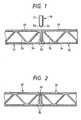
- the embodiment shown in Figure 1has a joint configuration of abutting type between hollow shape members 31, 32 as panels.
- the hollow shape members 31, 32have vertical plates 36, 36 at their ends in the width direction. Before the welding, the vertical plates 36, 36 are disposed immediately beneath a rotary tool 50. The vertical plates 36, 36 are opposed to each other in contact. If they are spaced apart, the distance is small and approximately 1 mm. On the extension of the interface between the vertical plates 36, 36 lies the center of a projection 52. The vertical plates 36, 36 have a stiffness strong enough to sustain the downward force mentioned earlier.
- the vertical plates 36are perpendicular to two plates 33, 34.
- the hollow shape members 31, 32are formed by extruding aluminum alloy.
- the upper and lower faces of the hollow shape member 31are flush with the corresponding upper and lower faces of the hollow shape member 32. That is, the hollow shape members 31, 32 have the same thickness. This is true also of the succeeding embodiments.
- the boundary 53 between a large-diameter portion 51 and the projection 52 of a small-diameter portion of the rotary tool 50is situated above the upper surfaces of the hollow shape members 31, 32.
- Numeral 35designates a plurality of members that are arranged in trusses to connect the two plates 36, 36.
- the hollow shape members 31, 32each have bilaterally symmetrical end portions.
- the hollow shape members 31, 32are mounted on a bed (not shown) and fixed immovably. The bed also lies under the vertical plates 36, 36.
- Friction stir weldingis performed by rotating the tool 50, plunging the projection 52 into the joint region of the hollow shape members 31, 32, and moving the projection 52 along the joint region.
- the rotating center of the projection 52is between the two vertical plates 36, 36.
- Figure 2shows the two panels after they are friction-welded.
- Reference number 45denotes the shape of a weld bead after welding.
- On the extension of the border line between the vertical plates 36, 36is situated the width center of the weld bead 45.
- the bead 45lies in an area on the extension of the thickness of the vertical plates 36, 36.
- the depth of the weld bead 45is determined by the height of the projection 52 at the lower end of the rotary tool 50 inserted in the joint region.
- the vertical plate 36may be holed for a lighter weight. This is true also of the succeeding embodiments.
- Welding of the lower sideis done by turning the hollow shape members upside down.
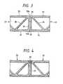
- the embodiment of Figure 3has a vertical plate 36 at the end of one hollow shape member 31 but not at the opposing end of the other hollow shape member 32. Corners in the vertical direction of the vertical plate 36 of the hollow shape member 31 are recessed so as to receive the ends of projecting pieces 38, 38 of the hollow shape member 32. These recessed portions are open in a direction of thickness of the hollow shape member 31 and in a direction perpendicular to the thickness direction (toward the hollow shape member 32 side). When the projecting pieces 38 are placed (superposed) on the recessed portions, there is actually a clearance between them although they are in contact with each other in the figure. There is also a gap between the front ends of these members (i.e., between the projecting pieces 38, 38 and the corners 33a, 34b).
- the abutting joint portions on the upper face side of the two hollow shape members 31, 32 and the vertical plate 36are situated directly below the center of the rotary tool 50.
- the rotating center of the projection 52 of the welding tool 50is disposed on an extension of the center line of the thickness of the vertical plate 36. That is, the joint region of the plate 33 (34) and plate 33 (34) is situated on the extension of the center line of the thickness of the vertical plate 36.
- the corners 33b, 34b extending from the plates 33, 34 to the recessed portionslie on an extension of the center line of the thickness of the vertical plate 36. Considering the gap between the corners 33b, 34b and the projecting pieces 38, the corners 33b, 34b are situated slightly to the left of the extension of the center line of the thickness of the vertical plate 36.
- the vertical plate 36has a rigidity to support the downward force.
- the horizontal gap between the front ends of the projecting pieces 38 and the hollow shape member 31is similar to that shown in Figure 1.
- the height of the projection 52 of the welding tool 50is approximately equal to the thickness of the projecting piece 38.
- the region that is plastic and fluidextends below the projecting piece 38, and comes to have an area larger than the diameter of the projection 52, and the two hollow shape members 31, 32 are friction-welded. It is desirable that the friction weld be so formed as to extend beyond the contact area between the underside of the projecting piece 38 and the vertical plate 36.
- Figure 4shows the state of the joint after being welded.
- the weld bead 45is formed such that the width center of the weld bead 45 is situated on an extension of the thickness center of the vertical plate 36.
- the rotating center of the tool 50be located on the extension of the center line of the thickness of the vertical plate 36.
- the corners 33b, 34bbe situated on the extension of the thickness center line of the vertical plate 36.
- the corners 33b, 34bbe positioned in the range between extension lines of thickness of the vertical plate 36, and at least a part of the projection 52 of the tool 50 be situated in the range.
- This arrangementenables the vertical plate 36 to receive at least a part of the vertical force, substantially preventing the deformation of the joint. As a result, a satisfactory joint can be formed.
- the bead 45is taken as a reference, although the bead 45 is slightly larger than the projection 52, the same as above can be said. This is true also of the other embodiments.
- this joint configurationcan minimize the surface sink of the joint region even when the horizontal gap between the projecting piece 38 and the hollow shape member 31 is large. As a result, the joint has a good appearance and requires a reduced amount of putty for painting. This is because the gap between the two members is terminated at a depth equal to the thickness of the projecting piece 38. It is also considered that this joint configuration can reduce the weight. Further, because one of the hollow members is fitted into the other, the positioning in the height direction of the two members can be accomplished easily.
- the ends of the hollow shape member 31are bilaterally symmetrical in shape.
- the hollow shape member 32are also bilaterally symmetrical.
- the hollow shape member 31has one end shaped as shown in Figure 3 and the other end shaped like the end of the hollow shape member 32 of Figure 3.
- the plate 36 of the hollow shape member 32may be removed.
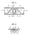
- Figure 7shows another embodiment, a variation of the preceding embodiment of Figure 5, in which the joint region of the two hollow shape members 31, 32 is provided with raised portions 37a, 38a protruding outside. This makes the joint region thick. The heights of the raised portions 37a, 38a are equal. Other parts are similar to those of Figure 5, except that the vertical plate 36 and the projections 37 are slightly thinner.
- the weld beadhas a sink corresponding to the volume of the lost material 41 that has flowed down by the downward force.
- the rotary tool 50plasticizes the raised portions 37a, 38a and forces them downward making up for the lost volume of the material 41.
- formation of sinkcan be prevented, providing a satisfactory welded joint.
- Figure 8shows the shape of bead 45 after welding. After welding, unnecessary parts, if any, are cut off as shown.
- the raised portions 37a, 38acan also be applied to Figure 1, 3 and 5 and to the subsequent embodiments.
- Figure 9shows a further embodiment, which allows welding at the upper and lower faces from only one side.
- the ends of the hollow shape members 31, 32 on the lower sidehave projecting pieces 34a, 34a protruding flush with the lower plates 34, 34 greatly toward the opposing hollow shape member sides.
- the front ends of the projecting pieces 34a, 34aare virtually in contact with each other.
- the front ends of the upper plates 33, 33are back from the front ends of the lower plates 34a, 34a.
- the front ends of the upper plates 33, 33are connected to the lower plates 34, 34 through the vertical plates 36, 36.
- the vertical plates 36, 36are connected to intermediate portions of the lower plates 34.
- the top portions of the vertical plates 36, 36are provided with recessed portions 39, 39 that receive a joint 60.
- the joint 60is mounted between the two hollow shape members 31, 32.
- the joint 60is T-shaped in vertical cross section.
- both ends of the joint 60are placed on the recessed portions 39, 39, the lower end of a vertical portion 61 has a clearance between it and the weld bead on the lower plate.
- the vertical portion 61may be omitted.
- This procedureallows the welding to be performed from one side and eliminates the inversion work. With the inversion work eliminated, there is an advantage that the time required for inversion and positioning and the inversion device are unnecessary, and even the assembly precision is improved.
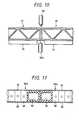
- Figure 10shows another embodiment, in which both the upper and lower sides of the hollow shape members 51, 52 are friction-welded at the same time.
- a rotary tool 50a for the lower sideis vertically below the welding tool 50 for the upper side.
- the projection 52 of the second welding tool 50afaces up.
- the two welding tools 50, 50a facing each otherare moved at the same speed to perform friction welding.
- Denoted 70, 70are beds (tables).
- the rotating centers of the tools 50 and 50aare on the same line, on which is the joint region of the hollow shape members 31, 32.
- the rotating center of the second tool 50ais positioned on the extension of the rotating center of the first tool 50, forces balance with each other allowing the joint to be welded in a short time with little deformation. Further, because there is no need to invert the hollow shape members 31, 32, the welding can be performed in a short time with little deformation of the joint.
- the honeycomb panels 80a, 80bcomprise two surface plates 81, 82, core members 83 having honeycomb-like cells, and edge members 84 arranged along the edges of the surface plates 81, 82, with the core members 83 and the edge members 84 soldered to the surface plates 81, 82 to form integral structures.
- the surface plates 81, 82, the core members 83 and the edge members 84are made of aluminum alloy.
- the edge members 84are made by extrusion and have a rectangular cross section. All sides of this rectangular cross section is larger in thickness than the surface plates 81, 82.
- the vertical sides of the mutually contacting edge members 84, 84have the same thickness as shown in Figure 1.
- the two honeycomb panels 80a, 80bhave the same thickness.
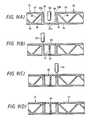
- the embodiment of Figure 11corresponds to the one shown in Figure 1.
- the height of the projection 52 of the rotary tool 50is larger than the thickness of the face plates 81, 82. This allows the face plates 81, 82 and the edge members 84, 84 to be welded.
- the load acting on the panels 80a, 80bis transmitted mainly by the edge members 84. After being fabricated, the panels 80a, 80b are assembled and friction-welded.
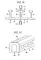
- the embodiment of Figure 12corresponds to the one shown in Figure 3.
- the edge member 84 of the honeycomb panel 80ahas a generally rectangular cross section and has recesses at the corners.
- the edge member 84 of the honeycomb panel 80bis like a channel, with its opening facing the honeycomb panel 80a.
- the open ends of the edge member 84are put on the recessed portions of the edge member 84 of the honeycomb panel 80a.
- honeycomb panel corresponding to Figure 5can be fabricated in a similar manner.
- FIG 13shows still another embodiment that corresponds to Figure 7.
- a plate 86is placed on the face plates 81, 81 and temporarily welded to them.
- the plate 86makes up for the material that is plasticized and flows out.
- one vertical piece of the edge member of the honeycomb panel 80ais removed. The vertical force is supported by the thickness of the horizontal piece of the edge member 84 and the surrounding parts.
- Figure 14shows a further embodiment of this invention.
- the preceding embodiments up to Figure 13includes panels having two faces (face plates), whereas the embodiment of Figure 14 includes panels 91, 92 having virtually a single face (face plates 94, 94).
- Friction weldingis performed at two locations, at the abutting ends of the panels 91, 92, the outside with face plates 94 and the inner side with no face plates. Therefore, the joint regions on the inner side are provided with narrow face plates (face plates 93, 93).
- the narrow face plates 93, 93are supported by vertical plates 96, 96. In this example, too, the vertical plates 96 are virtually perpendicular to the face plates 93, 94.
- the face plates 93, 94are provided with raised portions 37a, 38a similar to the ones shown in Figure 7.
- the face plates 94, 94have a plurality of reinforcing ribs (plates) 95, 95 at specified intervals.
- the ribs 95are T-shaped in cross section.
- the top surfaces of the ribs 95are flush with those of the face plates 93 of the joint region.
- reinforcing memberssuch as pillars
- the face platesalso 93, 93 serve as a seat for controlling the height of the tool 50.
- a movable body carrying the tool 50travels along the face plates 93, 93. Because of the provision of the face plates 93, 94, the panels 91, 92 can also be said to form a two-face structure.
- the panels 91, 92are extruded shape members.
- Figure 14shows the vertical plates 96, 96 of the panels 91 and 92 opposing each other at the joint region, as in the configuration of Figure 1, it is possible to place one of the vertical plates over the other, as shown in Figure 3, 5 and 7.
- Figure 15shows an example of application of this embodiment to the structural body of a railway car.
- the structural bodyhas side bodies 101, a roof body 102, a floor body 103, and gable bodies 104 at the ends in the longitudinal direction.
- the side bodies 101 and the roof body 102have panels 31, 32, 80a, 80b, 91, 92 whose long sides are oriented in the longitudinal direction of the car.
- the joining between the side bodies 101 and the roof body 102 and between the side bodies 101 and the floor body 103is accomplished by MIG welding.
- the roof body 102 and the side bodies 101are often shaped into arcs in cross section.
- the side having the vertical plates 96 and ribs 96is made to face to the interior of the car and the reinforcing members constitute pillars.
- the panels 31, 32 of Figure 9may be combined in a mirror-image arrangement.
- the end of the projecting plate 34a of each panelis placed on the recessed portion 39 of the plate 33 of the other panel. This obviates the use of the joint 60 and allows the simultaneous friction welding of the joint region both from above and below.
- the plates 33, 34acan be provided with raised portions, as shown in Figure 7.
Landscapes
- Engineering & Computer Science (AREA)
- Mechanical Engineering (AREA)
- Architecture (AREA)
- Civil Engineering (AREA)
- Structural Engineering (AREA)
- Life Sciences & Earth Sciences (AREA)
- Wood Science & Technology (AREA)
- Pressure Welding/Diffusion-Bonding (AREA)
- Standing Axle, Rod, Or Tube Structures Coupled By Welding, Adhesion, Or Deposition (AREA)
- Laminated Bodies (AREA)
- Connection Of Plates (AREA)
Abstract
Description
Claims (13)
- A metal member (31) suitable for use in frictionstir welding, having opposite first and second outerfaces extending in length and width directions of themember and facing outwardly in the thickness direction ofthe member in respectively opposite directions, therebeing, at a lateral edge of said first outer face, afirst rebate formation (33b) extending along said lateraledge and defined by a first surface facing laterally anda second surface facing outwardly in the thicknessdirection, and, at a lateral edge of said second outerface, a second rebate formation (34b) parallel to saidfirst rebate formation extending along said lateral edgeof said second outer face and defined by a third surfacefacing laterally in the same direction as said firstsurface and a fourth surface facing outwardly in theopposite direction with respect to said second surface.
- A member according to claim 1, comprising first andsecond parallel spaced webs (33, 34) providingrespectively said first and second outer faces and atleast one cross-web ((35, 36) connecting said first andsecond webs.
- A member according to claim 2, wherein said cross-web(35, 36) joins said first web at said lateral edgethereof.
- A member according to claim 3, wherein said cross-web(36) extends in the thickness direction substantially perpendicularly to said first web as seen in cross-sectionof the member, and said rebate formations (33b,34b) are aligned with the direction of said cross-web.
- A member according to claim 4, wherein said firstand third surfaces of said rebate formations are alignedwith a centre line of said cross-web, as seen in a cross-sectionof the member transverse to said lateral edges.
- A member according to claim 4, wherein said firstand third surfaces of said rebate formations are parallelto and offset from a centre line of said cross-web, asseen in a cross-section of the member transverse to saidlateral edges.
- A metal member suitable for use in friction stirwelding, having a structure comprising first and secondparallel spaced webs (33, 34) extending in length andwidth directions of said member and at least one cross-web(35, 36) connecting said first and second webs, thesebeing at a lateral edge of said first web a rebateformation (33b, 34b) extending along said lateral edgeand defined by a first surface facing laterally and asecond surface facing outwardly in the thicknessdirection.
- A member according to claim 7, wherein said cross-web(35, 36) joins said first web at said lateral edgethereof.
- A member according to claim 8, wherein, as seen in across-section transverse to said lateral edge, saidcross-web (36) extends in the thickness directionsubstantially perpendicularly to said first and secondwebs and said rebate formation (33b, 34b) is aligned withthe direction of said cross-web.
- A member according to claim 9, wherein said firstsurface of said rebate formation (33b, 34b) is alignedwith the centre-line of said cross-web.
- A member according to claim 9, wherein said firstsurface of said rebate formation is parallel to andoffset from the centre line of said cross-web.
- A method of friction stir welding wherein a firstmetal member according to any one of claims 1 to 11, isjoined by friction stir welding to a second metal member(32) by placing a lateral edge of said second metalmember in said rebate formation of said first metalmember and performing friction stir welding at saidrebate formation.
- A method of friction stir welding, wherein a firstmetal member according to any one of claims 1 to 6, isjoined by friction stir welding to a second metal member(32) which has first and second projecting parallel edgeportions, by placing said edge portions of said secondmetal member in said first and second rebate formations(33b, 34b) respectively and performing friction stirwelding at said rebate formations.
Applications Claiming Priority (3)
| Application Number | Priority Date | Filing Date | Title |
|---|---|---|---|
| JP6249196 | 1996-03-19 | ||
| JP6249196 | 1996-03-19 | ||
| EP97301870AEP0797043B1 (en) | 1996-03-19 | 1997-03-19 | Friction welding method |
Related Parent Applications (1)
| Application Number | Title | Priority Date | Filing Date |
|---|---|---|---|
| EP97301870ADivisionEP0797043B1 (en) | 1996-03-19 | 1997-03-19 | Friction welding method |
Publications (3)
| Publication Number | Publication Date |
|---|---|
| EP1222993A2true EP1222993A2 (en) | 2002-07-17 |
| EP1222993A3 EP1222993A3 (en) | 2002-07-24 |
| EP1222993B1 EP1222993B1 (en) | 2006-05-17 |
Family
ID=13201704
Family Applications (18)
| Application Number | Title | Priority Date | Filing Date |
|---|---|---|---|
| EP97301870AExpired - LifetimeEP0797043B1 (en) | 1996-03-19 | 1997-03-19 | Friction welding method |
| EP02004624AExpired - LifetimeEP1222997B1 (en) | 1996-03-19 | 1997-03-19 | Panel structure and a friction welding method |
| EP01126189AExpired - LifetimeEP1188507B1 (en) | 1996-03-19 | 1997-03-19 | Friction stir welding method |
| EP02004626AExpired - LifetimeEP1222999B1 (en) | 1996-03-19 | 1997-03-19 | Panel structure and a friction welding method |
| EP02004622AExpired - LifetimeEP1222995B1 (en) | 1996-03-19 | 1997-03-19 | Panel structure and a friction welding method |
| EP01126193AExpired - LifetimeEP1190808B1 (en) | 1996-03-19 | 1997-03-19 | Friction stir welding method, and a composite body produced thereby |
| EP06005613AExpired - LifetimeEP1679148B1 (en) | 1996-03-19 | 1997-03-19 | Panel structure, a friction welding method, and a panel |
| EP06005612AExpired - LifetimeEP1676667B1 (en) | 1996-03-19 | 1997-03-19 | Friction welding method for a panel structure |
| EP02004618AExpired - LifetimeEP1222991B1 (en) | 1996-03-19 | 1997-03-19 | Friction stir welding method of a panel structure |
| EP02004619AExpired - LifetimeEP1222992B1 (en) | 1996-03-19 | 1997-03-19 | Panel structure and a friction welding method |
| EP01126191AExpired - LifetimeEP1190806B1 (en) | 1996-03-19 | 1997-03-19 | Friction stir welding method and composite body produced thereby |
| EP01126190AWithdrawnEP1190805A3 (en) | 1996-03-19 | 1997-03-19 | Railway car body and related friction stir welding method |
| EP01126192AExpired - LifetimeEP1190807B1 (en) | 1996-03-19 | 1997-03-19 | Friction stir welding method and composite body produced thereby |
| EP02004623AExpired - LifetimeEP1222996B1 (en) | 1996-03-19 | 1997-03-19 | Panel structure and a friction welding method |
| EP02004621AExpired - LifetimeEP1222994B1 (en) | 1996-03-19 | 1997-03-19 | Panel structure for a friction welding method |
| EP02004625AExpired - LifetimeEP1222998B1 (en) | 1996-03-19 | 1997-03-19 | Panel structure and a friction welding method |
| EP06005615AExpired - LifetimeEP1676668B1 (en) | 1996-03-19 | 1997-03-19 | Panel structure |
| EP02004620AExpired - LifetimeEP1222993B1 (en) | 1996-03-19 | 1997-03-19 | Panel structure and a friction welding method |
Family Applications Before (17)
| Application Number | Title | Priority Date | Filing Date |
|---|---|---|---|
| EP97301870AExpired - LifetimeEP0797043B1 (en) | 1996-03-19 | 1997-03-19 | Friction welding method |
| EP02004624AExpired - LifetimeEP1222997B1 (en) | 1996-03-19 | 1997-03-19 | Panel structure and a friction welding method |
| EP01126189AExpired - LifetimeEP1188507B1 (en) | 1996-03-19 | 1997-03-19 | Friction stir welding method |
| EP02004626AExpired - LifetimeEP1222999B1 (en) | 1996-03-19 | 1997-03-19 | Panel structure and a friction welding method |
| EP02004622AExpired - LifetimeEP1222995B1 (en) | 1996-03-19 | 1997-03-19 | Panel structure and a friction welding method |
| EP01126193AExpired - LifetimeEP1190808B1 (en) | 1996-03-19 | 1997-03-19 | Friction stir welding method, and a composite body produced thereby |
| EP06005613AExpired - LifetimeEP1679148B1 (en) | 1996-03-19 | 1997-03-19 | Panel structure, a friction welding method, and a panel |
| EP06005612AExpired - LifetimeEP1676667B1 (en) | 1996-03-19 | 1997-03-19 | Friction welding method for a panel structure |
| EP02004618AExpired - LifetimeEP1222991B1 (en) | 1996-03-19 | 1997-03-19 | Friction stir welding method of a panel structure |
| EP02004619AExpired - LifetimeEP1222992B1 (en) | 1996-03-19 | 1997-03-19 | Panel structure and a friction welding method |
| EP01126191AExpired - LifetimeEP1190806B1 (en) | 1996-03-19 | 1997-03-19 | Friction stir welding method and composite body produced thereby |
| EP01126190AWithdrawnEP1190805A3 (en) | 1996-03-19 | 1997-03-19 | Railway car body and related friction stir welding method |
| EP01126192AExpired - LifetimeEP1190807B1 (en) | 1996-03-19 | 1997-03-19 | Friction stir welding method and composite body produced thereby |
| EP02004623AExpired - LifetimeEP1222996B1 (en) | 1996-03-19 | 1997-03-19 | Panel structure and a friction welding method |
| EP02004621AExpired - LifetimeEP1222994B1 (en) | 1996-03-19 | 1997-03-19 | Panel structure for a friction welding method |
| EP02004625AExpired - LifetimeEP1222998B1 (en) | 1996-03-19 | 1997-03-19 | Panel structure and a friction welding method |
| EP06005615AExpired - LifetimeEP1676668B1 (en) | 1996-03-19 | 1997-03-19 | Panel structure |
Country Status (6)
| Country | Link |
|---|---|
| US (24) | US6581819B1 (en) |
| EP (18) | EP0797043B1 (en) |
| JP (7) | JP2000202652A (en) |
| KR (13) | KR100445140B1 (en) |
| CN (20) | CN1165403C (en) |
| DE (17) | DE69739569D1 (en) |
Families Citing this family (182)
| Publication number | Priority date | Publication date | Assignee | Title |
|---|---|---|---|---|
| CN1165403C (en)* | 1996-03-19 | 2004-09-08 | 株式会社日立制作所 | Components for friction welding |
| JP3897391B2 (en)* | 1997-03-25 | 2007-03-22 | 昭和電工株式会社 | Friction stir welding method for metal joining members |
| GB9713209D0 (en)* | 1997-06-20 | 1997-08-27 | British Aerospace | Friction welding metal components |
| JP3070735B2 (en) | 1997-07-23 | 2000-07-31 | 株式会社日立製作所 | Friction stir welding method |
| JP3589863B2 (en) | 1997-07-23 | 2004-11-17 | 株式会社日立製作所 | Structure and friction stir welding method |
| SE9704800D0 (en)* | 1997-12-19 | 1997-12-19 | Esab Ab | Device for welding |
| US6051325A (en)* | 1997-12-23 | 2000-04-18 | Mcdonnell Douglas Corporation | Joining of machined sandwich assemblies by friction stir welding |
| US6745929B1 (en)* | 1998-06-16 | 2004-06-08 | Hitachi, Ltd. | Method of manufacturing structural body and structural body |
| JP3420502B2 (en)* | 1998-06-16 | 2003-06-23 | 株式会社日立製作所 | Structure |
| US6045028A (en) | 1998-07-17 | 2000-04-04 | Mcdonnell Douglas Corporation | Integral corrosion protection of friction-welded joints |
| AU733140B2 (en)* | 1998-09-29 | 2001-05-10 | Hitachi Limited | A friction stir welding method |
| JP3459193B2 (en) | 1999-05-26 | 2003-10-20 | 株式会社日立製作所 | Method of repairing friction stir welding and method of manufacturing railway vehicle |
| TW460346B (en)* | 1999-05-28 | 2001-10-21 | Hitachi Ltd | A manufacturing method of a structure body and a manufacturing apparatus of a structure body |
| TW464576B (en) | 1999-05-28 | 2001-11-21 | Hitachi Ltd | A structure body and a manufacturing method of a structure body |
| JP3481501B2 (en) | 1999-05-28 | 2003-12-22 | 株式会社日立製作所 | Structure and method of manufacturing the same |
| JP2000343245A (en)* | 1999-05-31 | 2000-12-12 | Hitachi Ltd | How to make a structure |
| TW449519B (en) | 1999-05-31 | 2001-08-11 | Hitachi Ltd | A manufacturing method of a structure body |
| DE19948441A1 (en)* | 1999-10-08 | 2001-04-12 | Abb Research Ltd | Device for joining metal sheets, working with heat generating rotating ceramic pin |
| JP3459210B2 (en) | 1999-11-24 | 2003-10-20 | 株式会社日立製作所 | Friction stir welding method |
| JP3538357B2 (en)* | 2000-01-24 | 2004-06-14 | 株式会社日立製作所 | Friction stir welding method |
| AU757401B2 (en)* | 2000-01-27 | 2003-02-20 | Hitachi Limited | Structure body |
| JP3552978B2 (en) | 2000-01-27 | 2004-08-11 | 株式会社日立製作所 | Hollow profile |
| JP3571601B2 (en)* | 2000-02-21 | 2004-09-29 | 株式会社日立製作所 | Friction stir welding method |
| JP3589930B2 (en)* | 2000-02-25 | 2004-11-17 | 株式会社日立製作所 | Friction stir welding method |
| JP3575748B2 (en) | 2000-03-06 | 2004-10-13 | 株式会社日立製作所 | Friction stir welding method |
| MXPA02010936A (en) | 2000-05-08 | 2004-09-06 | Univ Brigham Young | Friction stir weldin of metal matrix composites, ferrous alloys, non ferrous alloys, and superalloys using a superabrasive tool. |
| JP3781099B2 (en)* | 2000-06-02 | 2006-05-31 | トヨタ自動車株式会社 | Hollow product, fluid processing system, and method for joining hollow members |
| US6352193B1 (en) | 2000-08-01 | 2002-03-05 | General Electric Company | Apparatus for joining electrically conductive materials |
| JP2002086281A (en)* | 2000-09-13 | 2002-03-26 | Hitachi Ltd | Friction stir welding method |
| JP3818084B2 (en)* | 2000-12-22 | 2006-09-06 | 日立電線株式会社 | Cooling plate and manufacturing method thereof, and sputtering target and manufacturing method thereof |
| JP3761786B2 (en) | 2001-01-17 | 2006-03-29 | 株式会社日立製作所 | Friction stir welding method and apparatus |
| JP3751215B2 (en)* | 2001-04-16 | 2006-03-01 | 株式会社日立製作所 | Friction stir welding method |
| JP3725043B2 (en)* | 2001-04-25 | 2005-12-07 | 株式会社日立製作所 | Rail vehicle |
| US6732901B2 (en) | 2001-06-12 | 2004-05-11 | Brigham Young University Technology Transfer Office | Anvil for friction stir welding high temperature materials |
| US7152909B2 (en)* | 2001-06-22 | 2006-12-26 | East Manufacturing Corporation | Trailer and trailer body construction and extruded panel for same |
| JP2003095097A (en) | 2001-09-25 | 2003-04-03 | Hitachi Ltd | Rail vehicle |
| JP3725057B2 (en) | 2001-09-25 | 2005-12-07 | 株式会社日立製作所 | Rail vehicle |
| DE20200646U1 (en)* | 2002-01-17 | 2003-06-05 | Horst Witte Entwicklungs- und Vertriebs-KG, 21369 Nahrendorf | Sandwich panel for making workpiece clamping devices, comprises hollow profiles joined together by friction welding |
| DE20202108U1 (en)* | 2002-02-13 | 2003-06-26 | Horst Witte Entwicklungs- und Vertriebs-KG, 21369 Nahrendorf | Sandwich panel to build up workpiece fixtures |
| DE10226526A1 (en)* | 2002-06-14 | 2003-08-07 | Daimler Chrysler Ag | Running gear frame has interconnected frame sections with at least one frame section seam as a friction stir welded seam which extends three-dimensionally, and at least two frame sections are differently constructed |
| JP4647179B2 (en)* | 2002-09-11 | 2011-03-09 | 株式会社日立製作所 | Processing method |
| JP2006518671A (en) | 2003-01-30 | 2006-08-17 | スミス インターナショナル、インコーポレテッド | Out-of-position friction stir welding of high melting point materials |
| US7430888B2 (en)* | 2003-04-25 | 2008-10-07 | Showa Denko K.K. | Tubular metal body, method of producing same, liner for pressure vessel and method of producing same |
| WO2004101205A2 (en) | 2003-05-05 | 2004-11-25 | Smith International, Inc. | Applications of friction stir welding using a superabrasive tool |
| US6893594B2 (en)* | 2003-06-20 | 2005-05-17 | Kuei Yung Wang Chen | Extruded window and door composite frames |
| US6933057B2 (en)* | 2003-07-17 | 2005-08-23 | The Boeing Company | Friction stir welded assembly and method of forming a friction stir welded assembly |
| US7225968B2 (en) | 2003-08-04 | 2007-06-05 | Sii Megadiamond, Inc. | Crack repair using friction stir welding on materials including metal matrix composites, ferrous alloys, non-ferrous alloys, and superalloys |
| US7494040B2 (en)* | 2003-09-25 | 2009-02-24 | Sii Megadiamond, Inc. | Friction stir welding improvements for metal matrix composites, ferrous alloys, non-ferrous alloys, and superalloys using a superabrasive tool |
| US7225967B2 (en) | 2003-12-16 | 2007-06-05 | The Boeing Company | Structural assemblies and preforms therefor formed by linear friction welding |
| US7398911B2 (en)* | 2003-12-16 | 2008-07-15 | The Boeing Company | Structural assemblies and preforms therefor formed by friction welding |
| GB0329898D0 (en)* | 2003-12-23 | 2004-01-28 | Airbus Uk Ltd | Welding process for large structures |
| KR100608712B1 (en)* | 2004-01-06 | 2006-08-03 | 삼성전자주식회사 | Image data display device and display method |
| CA2492185A1 (en)* | 2004-01-08 | 2005-07-08 | Tecton Products | Pultruded building product |
| US20050166516A1 (en)* | 2004-01-13 | 2005-08-04 | Valinge Aluminium Ab | Floor covering and locking systems |
| US20050199372A1 (en)* | 2004-03-08 | 2005-09-15 | Frazer James T. | Cold plate and method of making the same |
| US20050210820A1 (en)* | 2004-03-24 | 2005-09-29 | Shinmaywa Industries, Ltd. | Frame and method for fabricating the same |
| US8186561B2 (en) | 2004-03-24 | 2012-05-29 | Megastir Technologies, LLC | Solid state processing of hand-held knife blades to improve blade performance |
| JP4485846B2 (en)* | 2004-05-11 | 2010-06-23 | 株式会社日立製作所 | Structure block manufacturing method and manufacturing apparatus |
| US7520099B2 (en)* | 2004-05-17 | 2009-04-21 | Tecton Products | Pultruded building product and system |
| US20050262791A1 (en)* | 2004-05-17 | 2005-12-01 | Todd Pringle | Siding and building product |
| US20060049234A1 (en)* | 2004-05-21 | 2006-03-09 | Flak Richard A | Friction stirring and its application to drill bits, oil field and mining tools, and components in other industrial applications |
| US20100078224A1 (en) | 2004-05-21 | 2010-04-01 | Smith International, Inc. | Ball hole welding using the friction stir welding (fsw) process |
| US7188686B2 (en)* | 2004-06-07 | 2007-03-13 | Varco I/P, Inc. | Top drive systems |
| JP4695355B2 (en)* | 2004-07-15 | 2011-06-08 | 新日本製鐵株式会社 | Boom / arm member for construction machine with excellent weld fatigue strength and method for manufacturing the same |
| US7841504B2 (en)* | 2004-09-21 | 2010-11-30 | The Boeing Company | Apparatus and system for welding self-fixtured preforms and associated method |
| CN100584510C (en)* | 2004-10-05 | 2010-01-27 | Sii米加钻石公司 | Expandable mandrel for use in friction stir welding and method of providing the mandrel |
| FR2879548B1 (en)* | 2004-12-17 | 2007-02-16 | Alstom Transport Sa | PANEL ASSEMBLY FOR THE CONSTRUCTION OF A RAIL VEHICLE BOX AND METHOD THEREOF |
| KR100780019B1 (en)* | 2005-02-01 | 2007-11-27 | 가부시끼가이샤 히다치 세이사꾸쇼 | Friction Stir Welding |
| US7473475B1 (en)* | 2005-05-13 | 2009-01-06 | Florida Turbine Technologies, Inc. | Blind weld configuration for a rotor disc assembly |
| JP5010117B2 (en)* | 2005-07-20 | 2012-08-29 | 株式会社神戸製鋼所 | Aluminum extruded hollow panel for automobile and manufacturing method thereof |
| BRPI0520507A2 (en)* | 2005-08-19 | 2009-05-12 | Airbus Espana Sl | composite material beams with bulb |
| US9266191B2 (en) | 2013-12-18 | 2016-02-23 | Aeroprobe Corporation | Fabrication of monolithic stiffening ribs on metallic sheets |
| US9511445B2 (en) | 2014-12-17 | 2016-12-06 | Aeroprobe Corporation | Solid state joining using additive friction stir processing |
| US9511446B2 (en) | 2014-12-17 | 2016-12-06 | Aeroprobe Corporation | In-situ interlocking of metals using additive friction stir processing |
| US8632850B2 (en) | 2005-09-26 | 2014-01-21 | Schultz-Creehan Holdings, Inc. | Friction fabrication tools |
| US8550326B2 (en) | 2005-10-05 | 2013-10-08 | Megastir Technologies Llc | Expandable mandrel for use in friction stir welding |
| US8056797B2 (en) | 2005-10-05 | 2011-11-15 | Megastir Technologies | Expandable mandrel for use in friction stir welding |
| DE102005048001B4 (en)* | 2005-10-06 | 2007-06-14 | Euro-Composites S.A., Zone Industrielle | connecting element |
| JP4531671B2 (en)* | 2005-10-12 | 2010-08-25 | 株式会社神戸製鋼所 | Hollow panel and manufacturing method thereof |
| US7353978B2 (en)* | 2005-10-13 | 2008-04-08 | The Boeing Company | Method of making tailored blanks using linear friction welding |
| SE530250C2 (en)* | 2006-03-08 | 2008-04-08 | Sapa Profiler Ab | Adjustable overlap joint and construction made by the same |
| JP4266024B2 (en)* | 2006-03-28 | 2009-05-20 | 株式会社日立製作所 | Rail vehicle, manufacturing method thereof, and hollow shape material used therefor |
| GB0616324D0 (en)* | 2006-08-16 | 2006-09-27 | Airbus Uk Ltd | A cover panel for an aircraft wing and a method of forming thereof |
| US20080047222A1 (en)* | 2006-08-23 | 2008-02-28 | Lockheed Martin Corporation | Friction stir welding process having enhanced corrosion performance |
| FR2907040B1 (en) | 2006-10-13 | 2009-06-26 | Alstom Transport Sa | METHOD FOR ASSEMBLING A STRUCTURE COMPRISING AN EXTERIOR AND AN INTERIOR CONSISTING OF A PLURALITY OF DOUBLE-SKIN ELEMENTS, SUCH AS A RAILWAY VEHICLE CASE, AND STRUCTURE OBTAINED |
| JP4882004B2 (en)* | 2006-11-03 | 2012-02-22 | 株式会社東洋鋼鐵 | Manufacturing apparatus and manufacturing method for reinforcing frame for display panel using aluminum alloy extruded material |
| KR100832241B1 (en)* | 2006-11-03 | 2008-05-28 | 주식회사동양강철 | Reinforcement frame for display panel using aluminum alloy extrusion and its manufacturing method |
| JP5094140B2 (en)* | 2006-11-09 | 2012-12-12 | 日野自動車株式会社 | Member joint structure |
| JP4972417B2 (en)* | 2006-12-15 | 2012-07-11 | 日野自動車株式会社 | Member joining method and structure |
| FR2912490B1 (en) | 2007-02-09 | 2010-10-29 | Alcan Rhenalu | METAL COMPOSITE PANEL AND METHOD OF MANUFACTURE |
| DE102007010262A1 (en)* | 2007-03-02 | 2008-09-04 | Siemens Ag | Lightweight structures, for use in e.g. vehicle bodywork, comprise sandwich panel with heat-sensitive core between two outer sheets, connectors at either end of the panel being welded to it using friction stir welding |
| US20080230584A1 (en)* | 2007-03-19 | 2008-09-25 | The Boeing Company | Method for Manufacturing a Workpiece by Friction Welding to Reduce the Occurrence of Abnormal Grain Growth |
| CN103722288B (en)* | 2007-06-14 | 2016-03-16 | 日本轻金属株式会社 | Bonding method |
| US20080311421A1 (en)* | 2007-06-15 | 2008-12-18 | United Technologies Corporation | Friction stir welded structures derived from AL-RE-TM alloys |
| US7624907B2 (en)* | 2007-06-15 | 2009-12-01 | Cyril Bath Company | Linear friction welding apparatus and method |
| US20080308197A1 (en)* | 2007-06-15 | 2008-12-18 | United Technologies Corporation | Secondary processing of structures derived from AL-RE-TM alloys |
| US20080308610A1 (en)* | 2007-06-15 | 2008-12-18 | United Technologies Corporation | Hollow structures formed with friction stir welding |
| US20100068550A1 (en)* | 2007-06-15 | 2010-03-18 | United Technologies Corporation | Hollow structures formed with friction stir welding |
| CN101772395B (en)* | 2007-08-10 | 2013-01-16 | 日本轻金属株式会社 | Joining method and method for manufacturing joined structure |
| WO2009022507A1 (en)* | 2007-08-10 | 2009-02-19 | Nippon Light Metal Company, Ltd. | Joining method and method of manufacturing joint structure |
| US7856790B2 (en)* | 2007-10-10 | 2010-12-28 | Tecton Products, Llc | Pultruded building product |
| US8376453B2 (en)* | 2007-11-30 | 2013-02-19 | Kyoraku Co., Ltd. | Hollow double-walled panel and interior panel for vehicle made using same |
| US8079126B2 (en)* | 2008-01-25 | 2011-12-20 | Pratt & Whitney Rocketdyne, Inc. | Friction stir welded bladder fuel tank |
| US20090223957A1 (en) | 2008-03-06 | 2009-09-10 | Hmt,Inc. | Welded full contact floating roof and method |
| US20090235608A1 (en)* | 2008-03-19 | 2009-09-24 | Jan Kosny | Support structures formed from triangular elements |
| US7762447B2 (en) | 2008-03-20 | 2010-07-27 | Ut-Battelle, Llc | Multiple pass and multiple layer friction stir welding and material enhancement processes |
| US8100316B2 (en)* | 2008-05-29 | 2012-01-24 | Airbus Operations Gmbh | Method for joining aircraft fuselage elements by friction stir welding (fsw) |
| US10252376B2 (en)* | 2009-03-03 | 2019-04-09 | U-Haul International, Inc. | Welded lap joint with corrosive-protective structure |
| DE202009003080U1 (en)* | 2009-03-04 | 2009-04-30 | Dy-Pack Verpackungen Gustav Dyckerhoff Gmbh | paper bags |
| KR101072373B1 (en) | 2009-04-13 | 2011-10-11 | 한국철도기술연구원 | Body for railway vehicles |
| FR2950017B1 (en)* | 2009-09-16 | 2017-07-07 | Alstom Transport Sa | METHOD OF MOUNTING A RAILWAY VEHICLE AND RAILWAY VEHICLE OBTAINED BY SAID METHOD |
| US20110079446A1 (en)* | 2009-10-05 | 2011-04-07 | Baker Hughes Incorporated | Earth-boring tools and components thereof and methods of attaching components of an earth-boring tool |
| KR101548792B1 (en) | 2009-11-02 | 2015-08-31 | 메가스터 테크놀로지스, 엘엘씨 | Out of position friction stir welding of casing and small diameter tubing or pipe |
| WO2011082311A2 (en)* | 2009-12-31 | 2011-07-07 | L.B. Foster Company | Conductor rail |
| US20110215614A1 (en)* | 2010-02-25 | 2011-09-08 | Ayyakannu Mani | Lightweight cross-car beam and method of constructing a structural member |
| NO331928B1 (en)* | 2010-03-31 | 2012-05-07 | Aker Engineering & Technology | Extruded elements |
| CN101804523B (en)* | 2010-04-23 | 2011-08-31 | 唐山轨道客车有限责任公司 | Welding method of butted section bars |
| US8881964B2 (en) | 2010-09-21 | 2014-11-11 | Ut-Battelle, Llc | Friction stir welding and processing of oxide dispersion strengthened (ODS) alloys |
| JP5237355B2 (en)* | 2010-11-26 | 2013-07-17 | 三菱重工業株式会社 | Method for manufacturing panel structure |
| CN103459081B (en)* | 2011-01-19 | 2016-05-25 | 日本轻金属株式会社 | Rotary tool unit, friction stir welding method, assembly of double-layer panels, and friction stir welding method of double-layer panels |
| CN103909343B (en)* | 2011-01-19 | 2016-04-27 | 日本轻金属株式会社 | Friction stirring connecting method |
| US20140103685A1 (en)* | 2011-02-23 | 2014-04-17 | Ayyakannu Mani | Lightweight Cross-Car Beam and Method of Construction |
| US8403390B2 (en)* | 2011-03-10 | 2013-03-26 | Shiloh Industries, Inc. | Vehicle panel assembly and method of attaching the same |
| KR101307294B1 (en)* | 2011-03-24 | 2013-09-12 | 주식회사동양강철 | Profile member for LNG storage tank of LNG carrier |
| KR101307295B1 (en)* | 2011-03-24 | 2013-09-12 | 주식회사동양강철 | Profile member assembly for LNG storage tank of LNG carrier |
| JP5575035B2 (en)* | 2011-03-29 | 2014-08-20 | 株式会社神戸製鋼所 | Car battery frame structure |
| JP5320439B2 (en)* | 2011-06-14 | 2013-10-23 | 株式会社日立製作所 | High corrosion resistance plant equipment |
| US8590767B2 (en)* | 2011-06-21 | 2013-11-26 | Research Institute Of Industrial Science & Technology | Method for welding hollow structure |
| WO2012175127A1 (en) | 2011-06-22 | 2012-12-27 | Sapa Ab | Friction stir welding tool with shoulders having different areas methods using such tool; product welded with such tool |
| US9468990B2 (en) | 2011-06-22 | 2016-10-18 | Sapa Ab | Friction stir welding tool with shoulders having different areas; methods using such tool; product welded with such tool |
| DE102011051728A1 (en)* | 2011-07-11 | 2013-01-17 | Thyssenkrupp Lasertechnik Gmbh | Method and device for producing tailor-made sheet-metal strips |
| JP5567530B2 (en)* | 2011-08-19 | 2014-08-06 | 日立オートモティブシステムズ株式会社 | Friction stir welding structure and power semiconductor device |
| US8561877B2 (en)* | 2011-10-27 | 2013-10-22 | GM Global Technology Operations LLC | Structural integrity welded assembly |
| US20130256060A1 (en)* | 2012-03-29 | 2013-10-03 | Safway Services, Llc | Scaffold Plank Structure |
| JP6047951B2 (en)* | 2012-06-29 | 2016-12-21 | スズキ株式会社 | Friction stir welding method of metal material and metal material joined body |
| RU2507113C1 (en)* | 2012-07-24 | 2014-02-20 | Федеральное государственное бюджетное образовательное учреждение высшего профессионального образования "Казанский национальный исследовательский технический университет им. А.Н. Туполева-КАИ" (КНИТУ-КАИ) | Honeycomb |
| CN103775136B (en)* | 2012-10-23 | 2015-06-10 | 中航商用航空发动机有限责任公司 | Vane |
| CN103047287B (en)* | 2012-12-31 | 2015-06-17 | 浙江工业大学 | Cone-shaped friction-free rotary air supply air floatation device |
| US20140255620A1 (en)* | 2013-03-06 | 2014-09-11 | Rolls-Royce Corporation | Sonic grain refinement of laser deposits |
| CN104235589A (en)* | 2013-06-16 | 2014-12-24 | 江苏新丽源南亚新材料有限公司 | Clamping groove type cellular board and manufacturing technology thereof |
| CN103406681A (en)* | 2013-08-09 | 2013-11-27 | 中国航空工业集团公司北京航空制造工程研究所 | Self-locking side-parting-resisting connector for stirring friction welding |
| US20180361501A1 (en)* | 2013-12-18 | 2018-12-20 | MELD Manufacturing Corporation | Meld solid-state joining of different features to cast parts |
| JP6248790B2 (en)* | 2014-05-08 | 2017-12-20 | 日本軽金属株式会社 | Friction stir welding method |
| JP6287751B2 (en)* | 2014-10-17 | 2018-03-07 | 日本軽金属株式会社 | Friction stir welding method |
| ES2809725T3 (en)* | 2015-02-24 | 2021-03-05 | Alumabridge Llc | Modular bridge deck system consisting of hollow extruded aluminum elements |
| CN107921575A (en)* | 2015-08-26 | 2018-04-17 | 日本轻金属株式会社 | Joint method, the manufacture method of liquid-cooled jacket cylinder and liquid-cooled jacket cylinder |
| CN105081596A (en)* | 2015-09-06 | 2015-11-25 | 唐山轨道客车有限责任公司 | Welding joint for friction stir welding |
| US9915046B2 (en)* | 2015-12-15 | 2018-03-13 | HFW Solutions, Inc. | Self alignment structure for applications joining extruded members |
| SE539953C2 (en)* | 2016-02-08 | 2018-02-06 | Nitiu Ab | A sandwich construction element comprising an open core structure of close packed asymmetric tetrahedrons |
| DE102016110572A1 (en)* | 2016-06-08 | 2017-12-14 | B. Braun Melsungen Ag | Medical-technical treatment chamber in lightweight construction |
| GB2552343A (en)* | 2016-07-19 | 2018-01-24 | Airbus Operations Ltd | Method of manufacturing a multi-alloy aerospace component |
| US10087618B2 (en)* | 2016-07-22 | 2018-10-02 | HFW Solutions, Inc. | System and method for interlocking structural members |
| US10549795B2 (en) | 2016-08-31 | 2020-02-04 | Wabash National L.P. | Floor assembly and floor securing apparatus |
| CN106735975B (en)* | 2016-12-19 | 2018-10-09 | 中车长春轨道客车股份有限公司 | Inboard width control method when aluminium alloy ground iron car welding of underframe |
| CA3039566C (en) | 2016-12-20 | 2021-04-13 | Michael Kloepfer | Cylindrical semi-trailer |
| CA3066401C (en) | 2016-12-20 | 2023-05-02 | Titan Trailers Inc. | Cylindrical cargo container construction |
| CN106801473B (en)* | 2017-03-24 | 2023-01-31 | 广东铝遊家科技有限公司 | Aluminum alloy structure house |
| JP2019025490A (en)* | 2017-07-25 | 2019-02-21 | 日本軽金属株式会社 | Joining method |
| US10759009B2 (en)* | 2017-09-11 | 2020-09-01 | Hitachi Automotive Systems Americas, Inc. | Friction stir welding flash and burr control |
| AU2018338411B2 (en) | 2017-09-22 | 2022-11-10 | Titan Trailers Inc. | Quasi-cylindrical cargo container and construction |
| CN107503439A (en)* | 2017-10-11 | 2017-12-22 | 广东铝遊家科技有限公司 | Aluminium alloy structure mobile house |
| JP7089034B2 (en) | 2017-10-31 | 2022-06-21 | メルド マニファクチャリング コーポレーション | Solid-state laminated modeling system as well as material composition and structural background |
| CN107989277B (en)* | 2017-12-30 | 2024-01-23 | 贵阳铝镁设计研究院有限公司 | Novel aluminum alloy structure wide goose plate |
| JP6681941B2 (en)* | 2018-05-31 | 2020-04-15 | 株式会社Uacj | Shock absorber |
| CN108644602A (en)* | 2018-06-28 | 2018-10-12 | 太仓新浏精密五金有限公司 | Die casting plank |
| DE102018211574B4 (en)* | 2018-07-12 | 2022-06-30 | Thyssenkrupp Ag | workpiece group |
| CN108723578B (en)* | 2018-07-18 | 2021-01-22 | 中车长春轨道客车股份有限公司 | Friction stir welding method for hollow aluminum profile splicing arc plate |
| USD880006S1 (en)* | 2018-08-17 | 2020-03-31 | Stage FX, Inc. | Truss |
| CN109296927B (en)* | 2018-10-31 | 2021-11-23 | 河北金维重工有限公司 | Integral sweep with high welding precision |
| CN109797905A (en)* | 2019-01-04 | 2019-05-24 | 中国华冶科工集团有限公司 | A kind of tube truss structure primary and secondary truss mutually passes through installation method |
| CN109835359B (en)* | 2019-03-07 | 2020-04-28 | 中车株洲电力机车有限公司 | Aluminum-based composite material rail vehicle |
| CN110126861A (en)* | 2019-05-08 | 2019-08-16 | 中车青岛四方机车车辆股份有限公司 | The roof side rail of vehicle |
| US11541440B2 (en) | 2019-07-25 | 2023-01-03 | National Research Council Of Canada | Snap-fit extrusions for forming panels |
| US11701737B2 (en) | 2019-09-10 | 2023-07-18 | Qingdao Cimc Reefer Trailer Co., Ltd. | Friction-stir-welded sheet-and-post sidewall |
| CN111014937B (en)* | 2019-11-25 | 2021-08-03 | 长春城际轨道客车配件有限公司 | Manufacturing method of metal structural member based on friction stir welding |
| CN111692172A (en)* | 2020-06-19 | 2020-09-22 | 中车唐山机车车辆有限公司 | Connecting piece, headwall and carriage |
| US12415690B2 (en)* | 2020-07-16 | 2025-09-16 | Motis, Llc | Trussed ramp |
| US12162703B2 (en) | 2020-07-16 | 2024-12-10 | Motis, Llc | Combination ramp and load levelers |
| GB2601393C (en)* | 2021-06-10 | 2023-02-22 | Altro Ltd | Improvements in or relating to flooring |
| CN115162513B (en)* | 2021-08-16 | 2023-09-19 | 任建利 | Arch structure frame, multi-curved cavity wall, power generation building and colorful power generation city |
| CN115285157A (en)* | 2022-09-05 | 2022-11-04 | 中车长春轨道客车股份有限公司 | Front end structure of magnetic-levitation train and magnetic-levitation train |
| DE102024103950A1 (en)* | 2024-02-13 | 2025-08-14 | SCHÜCO International KG | Method for producing an extruded composite profile and composite profile |
Family Cites Families (168)
| Publication number | Priority date | Publication date | Assignee | Title |
|---|---|---|---|---|
| US92889A (en)* | 1869-07-20 | Improvement in corn-planters | ||
| US11673A (en)* | 1854-09-12 | Cooking stove and range | ||
| US51601A (en)* | 1865-12-19 | Improvement in sawing-machines | ||
| US69834A (en)* | 1867-10-15 | palmbe | ||
| US27154A (en)* | 1860-02-14 | Straw-ctjtteb | ||
| US69835A (en)* | 1867-10-15 | Improved washing machine | ||
| US211819A (en)* | 1879-01-28 | Improvement in harrow-teeth | ||
| US74949A (en)* | 1868-02-25 | Improved washiko-maohine | ||
| US69833A (en)* | 1867-10-15 | Improved ioe-oeeam freezer | ||
| US42293A (en)* | 1864-04-12 | Improvement in balanced valves for steam-engines | ||
| US11671A (en)* | 1854-09-12 | Improved method of | ||
| US11672A (en)* | 1854-09-12 | Coknt-sheller | ||
| US1913342A (en)* | 1930-07-03 | 1933-06-06 | Truscon Steel Co | Metal structure |
| US1954511A (en)* | 1930-08-13 | 1934-04-10 | Youngstown Sheet And Tube Co | Method and apparatus for forming welded material |
| US2177868A (en)* | 1937-06-08 | 1939-10-31 | Comb Eng Co Inc | Welded joint |
| US2284229A (en)* | 1940-08-19 | 1942-05-26 | Palmer George Vincent | Metal wall building construction |
| GB572789A (en) | 1941-10-17 | 1945-10-24 | Hans Klopstock | An improved method of joining or welding metals |
| US2457129A (en)* | 1946-02-27 | 1948-12-28 | Metal Lumber Corp Of New Jerse | Hatch cover |
| US3301147A (en)* | 1963-07-22 | 1967-01-31 | Harvey Aluminum Inc | Vehicle-supporting matting and plank therefor |
| US3269072A (en)* | 1963-08-26 | 1966-08-30 | Pullman Inc | Vehicle floor construction |
| US3397496A (en)* | 1965-02-04 | 1968-08-20 | K & Associates Inc As | Locking means for roof and wall panel construction |
| US3385182A (en)* | 1965-09-27 | 1968-05-28 | Harvey Aluminum Inc | Interlocking device for load bearing surfaces such as aircraft landing mats |
| US3443306A (en)* | 1966-08-03 | 1969-05-13 | Nooter Corp | Method of joining clad material |
| US3348459A (en)* | 1967-01-03 | 1967-10-24 | Harvey Aluminum Inc | Interlocking matting and coupling bar therefor |
| US3386221A (en)* | 1967-09-08 | 1968-06-04 | Revere Copper & Brass Inc | Lightweight panel |
| IL31940A (en)* | 1968-04-05 | 1971-08-25 | Dynamit Nobel Ag | Sections from thermoplastic resins |
| US3538819A (en)* | 1968-07-26 | 1970-11-10 | Us Navy | Airfield matting locking pin |
| SE359479B (en)* | 1972-02-24 | 1973-09-03 | Platmanufaktur Ab | |
| US3849835A (en)* | 1972-09-19 | 1974-11-26 | Acme General Corp | Spring hinge for bifold doors |
| US3848871A (en) | 1973-04-19 | 1974-11-19 | A Sweet | Non-slipping hand grip for tennis racket and the like |
| US3849871A (en)* | 1973-08-06 | 1974-11-26 | Neander H | Method for welding pipes |
| US4019018A (en)* | 1974-09-30 | 1977-04-19 | Kobe Steel Ltd. | Process for narrow gap welding of aluminum alloy thick plates |
| DE2450747C2 (en)* | 1974-10-25 | 1976-08-26 | Talbot Waggonfab | TWO-AXLE RAIL VEHICLE WITH A TWISTABLE BASE |
| JPS51111925A (en) | 1975-03-27 | 1976-10-02 | Mitsutoshi Washizu | Tone generator for gas cock |
| US3984961A (en)* | 1975-08-04 | 1976-10-12 | Fruehauf Corporation | Composite extruded floor |
| DE2604882C2 (en)* | 1976-02-07 | 1986-06-26 | Klaus 8940 Memmingen Kaspar | Drive-on area for mechanical parking facilities, ramps, lifting platforms or the like. |
| JPS52123358A (en) | 1976-04-09 | 1977-10-17 | Shigeru Kimura | Frictional welding method |
| JPS5411250A (en) | 1977-06-10 | 1979-01-27 | Japan Synthetic Rubber Co Ltd | Production of powdery food |
| US4337708A (en)* | 1980-04-11 | 1982-07-06 | Pullman Incorporated | Railway car superstructure frame |
| GB2088195B (en) | 1980-11-18 | 1984-04-18 | British United Shoe Machinery | Apparatus for use in heat setting a lasted shoe upper |
| US4488833A (en)* | 1982-04-27 | 1984-12-18 | Kaiser Aluminum & Chemical Corporation | Rapidly deployed assault vehicle surfacing or trackway system |
| JPS60166177A (en) | 1984-02-07 | 1985-08-29 | Toshiba Corp | Fit welding between different kind metal |
| DE3406609C2 (en)* | 1984-02-23 | 1998-08-06 | Magnetbahn Gmbh | Car body for passenger cars of railways, local trains, magnetic levitation trains |
| AU566257B2 (en)* | 1985-01-10 | 1987-10-15 | Hockney Pty Ltd | Table top for lorry |
| SU1393566A1 (en) | 1985-10-08 | 1988-05-07 | Производственное Объединение "Вильнюсский Завод Топливной Аппаратуры Им.50-Летия Ссср" | Method of seam friction welding |
| JPS62189251A (en)* | 1986-02-13 | 1987-08-19 | 川崎重工業株式会社 | Floor structure |
| SE457809B (en)* | 1987-05-20 | 1989-01-30 | Lars Svensson | bridge deck |
| US4966082A (en)* | 1987-10-21 | 1990-10-30 | Hitachi, Ltd. | Construction and a manufacturing method of underframe for a rolling stock |
| JPH01148655A (en)* | 1987-12-04 | 1989-06-12 | Tokyu Car Corp | Structure for joining structure body of vehicle |
| JPH01244961A (en)* | 1988-03-25 | 1989-09-29 | Hitachi Ltd | Vehicle body structure |
| JP2669535B2 (en)* | 1988-06-06 | 1997-10-29 | 株式会社日立製作所 | Railcar body |
| SU1655725A1 (en) | 1988-06-27 | 1991-06-15 | Производственное Объединение "Вильнюсский Завод Топливной Аппаратуры Им.50-Летия Ссср" | Welding method |
| JP2679817B2 (en)* | 1988-08-16 | 1997-11-19 | ジャトコ株式会社 | Coupling structure of two-part rotary drum for automatic transmission |
| DE375591T1 (en)* | 1988-12-21 | 1990-10-18 | United Technologies Corp., Hartford, Conn. | IMPROVEMENT IN WELDING WELDING THROUGH THE USE OF STACKED WALL GEOMETRY. |
| US5267515A (en)* | 1989-01-18 | 1993-12-07 | Hitachi, Ltd. | Vehicle body construction having longitudinally elongated extruded panels and continuous welds joining the panels |
| US5098007A (en) | 1989-01-18 | 1992-03-24 | Hitachi, Ltd. | Method of manufacturing a vehicle body |
| IL89005A (en)* | 1989-01-19 | 1991-11-21 | Polygal | Lightweight construction panels with interconnectable edges |
| JP2604226B2 (en) | 1989-03-20 | 1997-04-30 | 財団法人 鉄道総合技術研究所 | Railcar structure |
| US4977722A (en)* | 1989-06-14 | 1990-12-18 | Repla Limited | Frame system |
| US5199632A (en)* | 1989-06-30 | 1993-04-06 | Hitachi. Ltd. | Railway car body structures and methods of making them |
| DE69031328T2 (en) | 1989-06-30 | 1998-04-02 | Hitachi Ltd | Passenger car structures and their manufacturing processes |
| JP2533663B2 (en) | 1989-06-30 | 1996-09-11 | 株式会社日立製作所 | Railway vehicle structure |
| GB8928881D0 (en)* | 1989-12-21 | 1990-02-28 | Avon Inflatables Ltd | Inflatable boat and deck therefor |
| US5433151A (en)* | 1990-09-07 | 1995-07-18 | Hitachi, Ltd. | Railway car body structures and methods of making them using welded honeycomb panels connected in an edge to edge relation |
| US5064097A (en) | 1990-10-10 | 1991-11-12 | Water Center International Ltd. | Compact water purification and beverage dispensing apparatus |
| US5188278A (en)* | 1990-11-22 | 1993-02-23 | A & S Corporation | Friction welding method for joining a rim and a disc of a disc wheel and the apparatus therefor |
| US5204149A (en)* | 1991-01-04 | 1993-04-20 | Case Designers Corporation | Method and apparatus for making double wall containers |
| US5298098A (en)* | 1991-03-22 | 1994-03-29 | Hoedl Herbert K | Industrial pallets and methods of manufacture of panel structures |
| JPH0645340A (en) | 1991-11-12 | 1994-02-18 | Rohm Co Ltd | Semiconductor device and manufacturing method thereof |
| JP2626372B2 (en)* | 1991-11-25 | 1997-07-02 | 株式会社日立製作所 | Vehicle |
| GB9125978D0 (en)* | 1991-12-06 | 1992-02-05 | Welding Inst | Hot shear butt welding |
| USD338968S (en)* | 1991-12-26 | 1993-08-31 | Certainteed Corporation | Window component extrusion |
| FR2691937B1 (en) | 1992-06-03 | 1994-07-22 | Alsthom Gec | RAILWAY VEHICLE BODY IN STAINLESS STEEL. |
| TW276225B (en) | 1992-07-17 | 1996-05-21 | Hitachi Seisakusyo Kk | |
| JP2692505B2 (en)* | 1992-08-21 | 1997-12-17 | 株式会社日立製作所 | Vehicle repair method and vehicle |
| JP3266325B2 (en)* | 1992-09-10 | 2002-03-18 | ▲滲▼透工業株式会社 | Heat exchange backing body |
| JP2773570B2 (en) | 1992-09-18 | 1998-07-09 | 株式会社日立製作所 | Laminated panel |
| JPH06106681A (en) | 1992-09-24 | 1994-04-19 | Toppan Printing Co Ltd | Paper container |
| GB9220273D0 (en) | 1992-09-25 | 1992-11-11 | Welding Inst | Improvements relating to friction jointing and surfacing |
| GB2272725B (en) | 1992-11-19 | 1995-06-14 | Southco | Slam latch |
| IT1257961B (en)* | 1992-12-30 | 1996-02-19 | Fiat Ferroviaria Spa | CASH STRUCTURE WITH CORRUGATED STRUCTURAL PANELS FOR RAILWAY VEHICLES. |
| JP2640078B2 (en)* | 1993-02-08 | 1997-08-13 | 株式会社神戸製鋼所 | Damping profiles and structures for transport aircraft |
| JP3110195B2 (en)* | 1993-03-16 | 2000-11-20 | 積水化学工業株式会社 | Side-by-side plate |
| JPH06328273A (en)* | 1993-05-20 | 1994-11-29 | Daido Steel Co Ltd | How to join metal rods or wires |
| JP3237037B2 (en)* | 1993-06-17 | 2001-12-10 | 株式会社日立製作所 | Friction welding device |
| JP2626471B2 (en) | 1993-06-22 | 1997-07-02 | 株式会社日立製作所 | Manufacturing method of vehicle structure |
| US5476210A (en)* | 1993-06-25 | 1995-12-19 | Fuji Jukogyo Kabushiki Kaisha | Structure for joining plate elements and method for joining the same |
| JPH06156271A (en)* | 1993-06-28 | 1994-06-03 | Hitachi Ltd | Railroad car structure and method for fabricating its block |
| US5450317A (en)* | 1993-11-24 | 1995-09-12 | U S West Advanced Technologies, Inc. | Method and system for optimized logistics planning |
| US5398805A (en) | 1993-12-13 | 1995-03-21 | Interfit International, Ltd. | Wear shoe retainer for a sludge collector flight |
| DE4342786A1 (en)* | 1993-12-15 | 1995-06-22 | Lignotock Gmbh | Friction welding method for fitting connectors to decorative vehicle panels |
| JP2544706B2 (en) | 1994-03-25 | 1996-10-16 | 富国工業株式会社 | Continuous press |
| NO942790D0 (en) | 1994-03-28 | 1994-07-27 | Norsk Hydro As | Method of friction welding and device for the same |
| JPH07266068A (en) | 1994-03-30 | 1995-10-17 | Kobe Steel Ltd | Method for laser beam welding aluminum or aluminum alloy member |
| US5480317A (en)* | 1994-03-31 | 1996-01-02 | Illinois Tool Works Inc. | Socket for receiving a threaded member which prevents cross-threading |
| JPH07205807A (en)* | 1994-08-31 | 1995-08-08 | Hitachi Ltd | Railway car body |
| US5811035A (en)* | 1995-06-06 | 1998-09-22 | The Marley Cooling Tower Company | Multiple purpose panel for cooling towers |
| US5665435A (en)* | 1995-08-31 | 1997-09-09 | University Of Pittsburgh Of The Commonwealth System Of Higher Education | Method for fluorination of diamond surfaces |
| NO954273D0 (en) | 1995-10-26 | 1995-10-26 | Norsk Hydro As | Wheels Wheel |
| US5651154A (en) | 1995-11-13 | 1997-07-29 | Reynolds Metals Company | Modular bridge deck system consisting of hollow extruded aluminum elements |
| US6199340B1 (en)* | 1996-01-22 | 2001-03-13 | L.B. Plastics Limited | Modular construction element |
| US5819491A (en)* | 1996-01-22 | 1998-10-13 | L.B. Plastics Limited | Modular construction elements |
| JP3807766B2 (en) | 1996-02-20 | 2006-08-09 | 株式会社日立製作所 | Manufacturing method of railway vehicle structure |
| US5611479A (en) | 1996-02-20 | 1997-03-18 | Rockwell International Corporation | Friction stir welding total penetration technique |
| CN1165403C (en)* | 1996-03-19 | 2004-09-08 | 株式会社日立制作所 | Components for friction welding |
| US5862975A (en)* | 1996-03-20 | 1999-01-26 | The Boeing Company | Composite/metal structural joint with welded Z-pins |
| US5713507A (en) | 1996-03-21 | 1998-02-03 | Rockwell International Corporation | Programmable friction stir welding process |
| US5664826A (en)* | 1996-04-12 | 1997-09-09 | Wilkens; Arthur L. | Light weight trailer walls with smooth surfaces |
| US5769306A (en) | 1996-05-31 | 1998-06-23 | The Boeing Company | Weld root closure method for friction stir welds |
| US5718366A (en) | 1996-05-31 | 1998-02-17 | The Boeing Company | Friction stir welding tool for welding variable thickness workpieces |
| US5794835A (en) | 1996-05-31 | 1998-08-18 | The Boeing Company | Friction stir welding |
| DK174563B1 (en)* | 1996-09-06 | 2003-06-10 | Daimlerchrysler Rail Systems | Cover plate and method of making such cover plate |
| US5697511A (en) | 1996-09-27 | 1997-12-16 | Boeing North American, Inc. | Tank and method of fabrication |
| US5836029A (en)* | 1996-10-22 | 1998-11-17 | Reynolds Metals Company | Method of preparing an aluminum bridge deck and an aluminum bridge deck configuration for receiving a wearing surface |
| US5829664A (en) | 1996-11-15 | 1998-11-03 | Aluminum Company Of America | Resistance heated stir welding |
| US5836128A (en)* | 1996-11-21 | 1998-11-17 | Crane Plastics Company Limited Partnership | Deck plank |
| JPH10193143A (en)* | 1997-01-17 | 1998-07-28 | Showa Alum Corp | Friction stir welding |
| JP3283433B2 (en) | 1997-01-31 | 2002-05-20 | 住友軽金属工業株式会社 | Manufacturing method of aluminum wide profile |
| JP3897391B2 (en)* | 1997-03-25 | 2007-03-22 | 昭和電工株式会社 | Friction stir welding method for metal joining members |
| ES2174209T3 (en)* | 1997-07-17 | 2002-11-01 | Alcan Tech & Man Ag | CONSTRUCTION WITH PROFILES AND COMPOSITE PLATES. |
| JP3070735B2 (en)* | 1997-07-23 | 2000-07-31 | 株式会社日立製作所 | Friction stir welding method |
| JP3589863B2 (en)* | 1997-07-23 | 2004-11-17 | 株式会社日立製作所 | Structure and friction stir welding method |
| US6085485A (en)* | 1997-12-11 | 2000-07-11 | Murdock; Douglas G. | Load bearing pre-fabricated building construction panel |
| SE9704800D0 (en)* | 1997-12-19 | 1997-12-19 | Esab Ab | Device for welding |
| US6290117B1 (en)* | 1998-02-17 | 2001-09-18 | Hitachi, Ltd. | Friction stir welding method and friction stir welding apparatus |
| US6045027A (en)* | 1998-03-04 | 2000-04-04 | The Boeing Company | Friction stir welding interlocking joint design and method |
| JP3420502B2 (en)* | 1998-06-16 | 2003-06-23 | 株式会社日立製作所 | Structure |
| US6082810A (en)* | 1998-09-18 | 2000-07-04 | Utility Trailer Manufacturing Company | Cargo vehicle floor construction and method |
| AU733140B2 (en)* | 1998-09-29 | 2001-05-10 | Hitachi Limited | A friction stir welding method |
| CA2293907A1 (en)* | 1999-01-04 | 2000-07-04 | Sooner Trailer Manufacturing Co. | Trailer with improved double skin slat construction |
| JP3459187B2 (en)* | 1999-02-02 | 2003-10-20 | 株式会社日立製作所 | Hollow profile |
| JP3459193B2 (en)* | 1999-05-26 | 2003-10-20 | 株式会社日立製作所 | Method of repairing friction stir welding and method of manufacturing railway vehicle |
| TW464576B (en)* | 1999-05-28 | 2001-11-21 | Hitachi Ltd | A structure body and a manufacturing method of a structure body |
| JP3481501B2 (en)* | 1999-05-28 | 2003-12-22 | 株式会社日立製作所 | Structure and method of manufacturing the same |
| JP2000351365A (en)* | 1999-06-11 | 2000-12-19 | Hitachi Ltd | Car body |
| US6986452B2 (en)* | 1999-09-03 | 2006-01-17 | Lockheed Martin Corporation | Friction stir welding as a rivet replacement technology |
| AU7475200A (en)* | 1999-09-03 | 2001-04-10 | Lockheed Martin Corporation | Friction stir welding as a rivet replacement technology |
| JP3459210B2 (en)* | 1999-11-24 | 2003-10-20 | 株式会社日立製作所 | Friction stir welding method |
| US6722286B2 (en)* | 1999-12-14 | 2004-04-20 | Hitachi, Ltd. | Structure and railway car |
| JP3538357B2 (en)* | 2000-01-24 | 2004-06-14 | 株式会社日立製作所 | Friction stir welding method |
| JP3552978B2 (en)* | 2000-01-27 | 2004-08-11 | 株式会社日立製作所 | Hollow profile |
| JP3589930B2 (en)* | 2000-02-25 | 2004-11-17 | 株式会社日立製作所 | Friction stir welding method |
| US6324796B1 (en)* | 2000-04-10 | 2001-12-04 | Homeland Vinyl Products, Inc. | Modular decking planks |
| US6398883B1 (en)* | 2000-06-07 | 2002-06-04 | The Boeing Company | Friction stir grain refinement of structural members |
| US6729097B2 (en)* | 2000-10-12 | 2004-05-04 | Armstrong World Industries, Inc. | Hollow building panel having an angled support member and method of making same |
| JP3575749B2 (en)* | 2000-11-17 | 2004-10-13 | 株式会社日立製作所 | Friction stir welding method |
| JP3553012B2 (en)* | 2000-11-17 | 2004-08-11 | 株式会社日立製作所 | Friction stir welding method |
| EP1264321B1 (en)* | 2000-11-30 | 2006-08-16 | Showa Denko K.K. | Niobium powder for capacitor, sintered body thereof and capacitor using the sintered body |
| US6769595B2 (en)* | 2000-12-20 | 2004-08-03 | Alcoa Inc. | Friction plunge riveting |
| JP3675714B2 (en)* | 2000-12-20 | 2005-07-27 | 株式会社日立製作所 | Railway vehicle wife manufacturing method and rail car body |
| US6425626B1 (en)* | 2001-01-04 | 2002-07-30 | Michael Kloepfer | Truck/trailer box constructions |
| JP3761786B2 (en)* | 2001-01-17 | 2006-03-29 | 株式会社日立製作所 | Friction stir welding method and apparatus |
| USD459491S1 (en)* | 2001-01-31 | 2002-06-25 | Becht Engineering Company, Inc. | Deck slat |
| US6871600B2 (en)* | 2001-02-09 | 2005-03-29 | Trn Business Trust | Pultruded panel |
| US20020119336A1 (en)* | 2001-02-26 | 2002-08-29 | Takeshi Kawasaki | Method of friction stir welding structural body, structural body, and extruded material |
| US20040074949A1 (en)* | 2001-03-07 | 2004-04-22 | Masayuki Narita | Friction agitation joining method flat material for plastic working and closed end sleeve like body |
| US6550397B2 (en)* | 2001-03-27 | 2003-04-22 | Hitachi, Ltd. | Car body |
| JP3751215B2 (en)* | 2001-04-16 | 2006-03-01 | 株式会社日立製作所 | Friction stir welding method |
| US6669271B2 (en)* | 2001-06-22 | 2003-12-30 | East Manufacturing Corporation | Smooth side body structure and method |
| JP3751237B2 (en)* | 2001-09-03 | 2006-03-01 | 株式会社日立製作所 | Friction stir welding connection material |
| JP3725057B2 (en)* | 2001-09-25 | 2005-12-07 | 株式会社日立製作所 | Rail vehicle |
| JP3929816B2 (en)* | 2002-04-16 | 2007-06-13 | 株式会社日立製作所 | Hairline processing method |
| US6918221B2 (en)* | 2002-08-08 | 2005-07-19 | Robert M. Williams | Polymeric deck panels, deck assemblies, decks and methods for forming the same |
| JP4440522B2 (en)* | 2002-09-11 | 2010-03-24 | 株式会社日立製作所 | Hollow profile for friction stir welding |
| JP2003136258A (en)* | 2002-09-11 | 2003-05-14 | Hitachi Ltd | Friction stir welding method |
| US6739106B2 (en)* | 2002-09-12 | 2004-05-25 | Royal Group Technologies Limited | Reversible plastic building board with different colored sides |
| US6933057B2 (en)* | 2003-07-17 | 2005-08-23 | The Boeing Company | Friction stir welded assembly and method of forming a friction stir welded assembly |
| JP4205537B2 (en)* | 2003-09-04 | 2009-01-07 | 株式会社日立製作所 | Friction stir welding method |
- 1997
- 1997-03-18CNCNB011114983Apatent/CN1165403C/ennot_activeExpired - Fee Related
- 1997-03-18CNCNB2004101046013Apatent/CN1322241C/ennot_activeExpired - Fee Related
- 1997-03-18CNCNB2006100943947Apatent/CN100441935C/ennot_activeExpired - Fee Related
- 1997-03-18CNCNB2004101046719Apatent/CN1322242C/ennot_activeExpired - Fee Related
- 1997-03-18CNCNB2006100998206Apatent/CN100475411C/ennot_activeExpired - Fee Related
- 1997-03-18CNCNB2006100943932Apatent/CN100531997C/ennot_activeExpired - Fee Related
- 1997-03-18KRKR1019970009067Apatent/KR100445140B1/ennot_activeExpired - Lifetime
- 1997-03-18CNCN2006100943928Apatent/CN1880002B/ennot_activeExpired - Fee Related
- 1997-03-18USUS08/820,231patent/US6581819B1/ennot_activeExpired - Fee Related
- 1997-03-18CNCNB971034974Apatent/CN1203954C/ennot_activeExpired - Fee Related
- 1997-03-18CNCNB2004100949164Apatent/CN1310732C/ennot_activeExpired - Fee Related
- 1997-03-19EPEP97301870Apatent/EP0797043B1/ennot_activeExpired - Lifetime
- 1997-03-19EPEP02004624Apatent/EP1222997B1/ennot_activeExpired - Lifetime
- 1997-03-19DEDE69739569Tpatent/DE69739569D1/ennot_activeExpired - Lifetime
- 1997-03-19DEDE69734367Tpatent/DE69734367T2/ennot_activeExpired - Lifetime
- 1997-03-19EPEP01126189Apatent/EP1188507B1/ennot_activeExpired - Lifetime
- 1997-03-19EPEP02004626Apatent/EP1222999B1/ennot_activeExpired - Lifetime
- 1997-03-19DEDE69740067Tpatent/DE69740067D1/ennot_activeExpired - Lifetime
- 1997-03-19EPEP02004622Apatent/EP1222995B1/ennot_activeExpired - Lifetime
- 1997-03-19DEDE69732669Tpatent/DE69732669T2/ennot_activeExpired - Lifetime
- 1997-03-19EPEP01126193Apatent/EP1190808B1/ennot_activeExpired - Lifetime
- 1997-03-19DEDE69736958Tpatent/DE69736958T2/ennot_activeExpired - Lifetime
- 1997-03-19EPEP06005613Apatent/EP1679148B1/ennot_activeExpired - Lifetime
- 1997-03-19DEDE69736959Tpatent/DE69736959T2/ennot_activeExpired - Lifetime
- 1997-03-19EPEP06005612Apatent/EP1676667B1/ennot_activeExpired - Lifetime
- 1997-03-19EPEP02004618Apatent/EP1222991B1/ennot_activeExpired - Lifetime
- 1997-03-19DEDE69739407Tpatent/DE69739407D1/ennot_activeExpired - Lifetime
- 1997-03-19DEDE69735144Tpatent/DE69735144T2/ennot_activeExpired - Lifetime
- 1997-03-19DEDE69734368Tpatent/DE69734368T2/ennot_activeExpired - Lifetime
- 1997-03-19EPEP02004619Apatent/EP1222992B1/ennot_activeExpired - Lifetime
- 1997-03-19EPEP01126191Apatent/EP1190806B1/ennot_activeExpired - Lifetime
- 1997-03-19EPEP01126190Apatent/EP1190805A3/ennot_activeWithdrawn
- 1997-03-19DEDE69736017Tpatent/DE69736017T2/ennot_activeExpired - Lifetime
- 1997-03-19DEDE69732191Tpatent/DE69732191T2/ennot_activeExpired - Lifetime
- 1997-03-19EPEP01126192Apatent/EP1190807B1/ennot_activeExpired - Lifetime
- 1997-03-19DEDE69732260Tpatent/DE69732260T2/ennot_activeExpired - Lifetime
- 1997-03-19DEDE69735964Tpatent/DE69735964T2/ennot_activeExpired - Lifetime
- 1997-03-19EPEP02004623Apatent/EP1222996B1/ennot_activeExpired - Lifetime
- 1997-03-19EPEP02004621Apatent/EP1222994B1/ennot_activeExpired - Lifetime
- 1997-03-19DEDE69732670Tpatent/DE69732670T2/ennot_activeExpired - Lifetime
- 1997-03-19DEDE69735388Tpatent/DE69735388T2/ennot_activeExpired - Lifetime
- 1997-03-19DEDE69722493Tpatent/DE69722493T2/ennot_activeExpired - Lifetime
- 1997-03-19EPEP02004625Apatent/EP1222998B1/ennot_activeExpired - Lifetime
- 1997-03-19DEDE69735905Tpatent/DE69735905T2/ennot_activeExpired - Lifetime
- 1997-03-19EPEP06005615Apatent/EP1676668B1/ennot_activeExpired - Lifetime
- 1997-03-19EPEP02004620Apatent/EP1222993B1/ennot_activeExpired - Lifetime
- 1999
- 1999-06-18CNCNB991084934Apatent/CN1208165C/ennot_activeExpired - Fee Related
- 2000
- 2000-02-24JPJP2000047767Apatent/JP2000202652A/ennot_activeAbandoned
- 2000-02-24JPJP2000047585Apatent/JP2000205218A/enactivePending
- 2000-02-24JPJP2000047766Apatent/JP2000202651A/enactivePending
- 2000-02-24JPJP2000047583Apatent/JP2000205216A/enactivePending
- 2000-02-24JPJP2000047582Apatent/JP2000202650A/enactivePending
- 2000-02-24JPJP2000047584Apatent/JP2000205217A/enactivePending
- 2000-02-24JPJP2000047768Apatent/JP2000202653A/ennot_activeAbandoned
- 2001
- 2001-02-19KRKR1020010008233Apatent/KR100428552B1/ennot_activeExpired - Fee Related
- 2001-02-19KRKR1020010008235Apatent/KR100459094B1/ennot_activeExpired - Fee Related
- 2001-02-19KRKR1020010008240Apatent/KR100426025B1/ennot_activeExpired - Fee Related
- 2001-02-19KRKR1020010008232Apatent/KR100426021B1/ennot_activeExpired - Fee Related
- 2001-02-19KRKR1020010008238Apatent/KR100426023B1/ennot_activeExpired - Fee Related
- 2001-02-19KRKR1020010008234Apatent/KR100428553B1/ennot_activeExpired - Fee Related
- 2001-02-19KRKR1020010008239Apatent/KR100426024B1/ennot_activeExpired - Fee Related
- 2001-02-19KRKR1020010008229Apatent/KR100428539B1/ennot_activeExpired - Lifetime
- 2001-02-19KRKR1020010008231Apatent/KR100428544B1/ennot_activeExpired - Fee Related
- 2001-02-19KRKR1020010008237Apatent/KR100426022B1/ennot_activeExpired - Fee Related
- 2001-02-19KRKR1020010008230Apatent/KR100445136B1/ennot_activeExpired - Fee Related
- 2001-02-19KRKR1020010008236Apatent/KR100428554B1/ennot_activeExpired - Fee Related
- 2001-03-16CNCNB011118059Apatent/CN1208166C/ennot_activeExpired - Fee Related
- 2001-03-16CNCNB011118024Apatent/CN1203957C/ennot_activeExpired - Fee Related
- 2001-03-16CNCNB011118075Apatent/CN1199756C/ennot_activeExpired - Fee Related
- 2001-03-16CNCNB011118032Apatent/CN1211180C/ennot_activeExpired - Fee Related
- 2001-03-16CNCNB011118016Apatent/CN1203956C/ennot_activeExpired - Fee Related
- 2001-03-16CNCNB011114967Apatent/CN1192847C/ennot_activeExpired - Fee Related
- 2001-03-16CNCNB011118067Apatent/CN1208167C/ennot_activeExpired - Fee Related
- 2001-03-16CNCN01111497Apatent/CN1322650A/enactivePending
- 2001-03-16CNCN011118040Apatent/CN1216713C/ennot_activeExpired - Fee Related
- 2001-03-16CNCNB011114991Apatent/CN1192848C/ennot_activeExpired - Fee Related
- 2003
- 2003-06-23USUS10/600,577patent/US6983873B2/ennot_activeExpired - Fee Related
- 2003-06-23USUS10/600,576patent/US7032804B2/ennot_activeExpired - Fee Related
- 2003-06-23USUS10/600,616patent/US7114304B2/ennot_activeExpired - Fee Related
- 2003-06-23USUS10/600,607patent/US6966481B2/ennot_activeExpired - Fee Related
- 2003-06-23USUS10/600,610patent/US6946206B2/ennot_activeExpired - Fee Related
- 2003-06-23USUS10/600,617patent/US7520104B2/ennot_activeExpired - Fee Related
- 2003-06-23USUS10/600,574patent/US7416769B2/ennot_activeExpired - Fee Related
- 2003-06-23USUS10/600,608patent/US7056594B2/ennot_activeExpired - Fee Related
- 2003-06-23USUS10/600,614patent/US6840426B2/ennot_activeExpired - Fee Related
- 2003-06-23USUS10/600,613patent/US7178303B2/ennot_activeExpired - Fee Related
- 2003-06-23USUS10/600,572patent/US6862860B2/ennot_activeExpired - Lifetime
- 2003-06-23USUS10/600,611patent/US7032805B2/ennot_activeExpired - Fee Related
- 2003-06-23USUS10/600,615patent/US6978923B2/ennot_activeExpired - Fee Related
- 2003-06-23USUS10/600,573patent/US7073701B2/ennot_activeExpired - Fee Related
- 2003-06-23USUS10/600,575patent/US6953144B2/ennot_activeExpired - Fee Related
- 2003-06-23USUS10/600,618patent/US20040025741A1/ennot_activeAbandoned
- 2005
- 2005-03-21USUS11/084,020patent/US7562802B2/ennot_activeExpired - Fee Related
- 2006
- 2006-04-14USUS11/403,811patent/US7413107B2/ennot_activeExpired - Fee Related
- 2006-04-14USUS11/403,812patent/US7513409B2/ennot_activeExpired - Fee Related
- 2006-06-15USUS11/453,034patent/US7665651B2/ennot_activeExpired - Fee Related
- 2006-06-15USUS11/452,938patent/US7287683B2/ennot_activeExpired - Fee Related
- 2006-06-15USUS11/453,147patent/US20060254188A1/ennot_activeAbandoned
- 2010
- 2010-07-28USUS12/805,385patent/US20100297469A1/ennot_activeAbandoned
Also Published As
Similar Documents
| Publication | Publication Date | Title |
|---|---|---|
| EP0797043B1 (en) | Friction welding method |
Legal Events
| Date | Code | Title | Description |
|---|---|---|---|
| PUAI | Public reference made under article 153(3) epc to a published international application that has entered the european phase | Free format text:ORIGINAL CODE: 0009012 | |
| PUAL | Search report despatched | Free format text:ORIGINAL CODE: 0009013 | |
| AC | Divisional application: reference to earlier application | Ref document number:797043 Country of ref document:EP | |
| AK | Designated contracting states | Kind code of ref document:A2 Designated state(s):DE FR GB IT SE | |
| AK | Designated contracting states | Kind code of ref document:A3 Designated state(s):DE FR GB IT SE | |
| 17P | Request for examination filed | Effective date:20030116 | |
| AKX | Designation fees paid | Designated state(s):DE FR GB IT SE | |
| 17Q | First examination report despatched | Effective date:20040617 | |
| GRAP | Despatch of communication of intention to grant a patent | Free format text:ORIGINAL CODE: EPIDOSNIGR1 | |
| GRAS | Grant fee paid | Free format text:ORIGINAL CODE: EPIDOSNIGR3 | |
| GRAA | (expected) grant | Free format text:ORIGINAL CODE: 0009210 | |
| AC | Divisional application: reference to earlier application | Ref document number:0797043 Country of ref document:EP Kind code of ref document:P | |
| AK | Designated contracting states | Kind code of ref document:B1 Designated state(s):DE FR GB IT SE | |
| PG25 | Lapsed in a contracting state [announced via postgrant information from national office to epo] | Ref country code:IT Free format text:LAPSE BECAUSE OF FAILURE TO SUBMIT A TRANSLATION OF THE DESCRIPTION OR TO PAY THE FEE WITHIN THE PRESCRIBED TIME-LIMIT;WARNING: LAPSES OF ITALIAN PATENTS WITH EFFECTIVE DATE BEFORE 2007 MAY HAVE OCCURRED AT ANY TIME BEFORE 2007. THE CORRECT EFFECTIVE DATE MAY BE DIFFERENT FROM THE ONE RECORDED. Effective date:20060517 | |
| REG | Reference to a national code | Ref country code:GB Ref legal event code:FG4D | |
| REF | Corresponds to: | Ref document number:69735905 Country of ref document:DE Date of ref document:20060622 Kind code of ref document:P | |
| REG | Reference to a national code | Ref country code:SE Ref legal event code:TRGR | |
| ET | Fr: translation filed | ||
| PLBE | No opposition filed within time limit | Free format text:ORIGINAL CODE: 0009261 | |
| STAA | Information on the status of an ep patent application or granted ep patent | Free format text:STATUS: NO OPPOSITION FILED WITHIN TIME LIMIT | |
| 26N | No opposition filed | Effective date:20070220 | |
| PGFP | Annual fee paid to national office [announced via postgrant information from national office to epo] | Ref country code:FR Payment date:20120319 Year of fee payment:16 | |
| PGFP | Annual fee paid to national office [announced via postgrant information from national office to epo] | Ref country code:GB Payment date:20120314 Year of fee payment:16 Ref country code:IT Payment date:20120319 Year of fee payment:16 Ref country code:SE Payment date:20120313 Year of fee payment:16 | |
| PGFP | Annual fee paid to national office [announced via postgrant information from national office to epo] | Ref country code:DE Payment date:20120411 Year of fee payment:16 | |
| REG | Reference to a national code | Ref country code:SE Ref legal event code:EUG | |
| PG25 | Lapsed in a contracting state [announced via postgrant information from national office to epo] | Ref country code:SE Free format text:LAPSE BECAUSE OF NON-PAYMENT OF DUE FEES Effective date:20130320 | |
| GBPC | Gb: european patent ceased through non-payment of renewal fee | Effective date:20130319 | |
| REG | Reference to a national code | Ref country code:FR Ref legal event code:ST Effective date:20131129 | |
| REG | Reference to a national code | Ref country code:DE Ref legal event code:R119 Ref document number:69735905 Country of ref document:DE Effective date:20131001 | |
| PG25 | Lapsed in a contracting state [announced via postgrant information from national office to epo] | Ref country code:GB Free format text:LAPSE BECAUSE OF NON-PAYMENT OF DUE FEES Effective date:20130319 Ref country code:DE Free format text:LAPSE BECAUSE OF NON-PAYMENT OF DUE FEES Effective date:20131001 Ref country code:FR Free format text:LAPSE BECAUSE OF NON-PAYMENT OF DUE FEES Effective date:20130402 | |
| PG25 | Lapsed in a contracting state [announced via postgrant information from national office to epo] | Ref country code:IT Free format text:LAPSE BECAUSE OF NON-PAYMENT OF DUE FEES Effective date:20130319 |