EP1221307A2 - Method of forming medical devices, intravascular occlusion devices - Google Patents
Method of forming medical devices, intravascular occlusion devicesDownload PDFInfo
- Publication number
- EP1221307A2 EP1221307A2EP02076318AEP02076318AEP1221307A2EP 1221307 A2EP1221307 A2EP 1221307A2EP 02076318 AEP02076318 AEP 02076318AEP 02076318 AEP02076318 AEP 02076318AEP 1221307 A2EP1221307 A2EP 1221307A2
- Authority
- EP
- European Patent Office
- Prior art keywords
- fabric
- guidewire
- basket
- molding
- molding element
- Prior art date
- Legal status (The legal status is an assumption and is not a legal conclusion. Google has not performed a legal analysis and makes no representation as to the accuracy of the status listed.)
- Granted
Links
Images


Classifications
- A—HUMAN NECESSITIES
- A61—MEDICAL OR VETERINARY SCIENCE; HYGIENE
- A61B—DIAGNOSIS; SURGERY; IDENTIFICATION
- A61B17/00—Surgical instruments, devices or methods
- A61B17/0057—Implements for plugging an opening in the wall of a hollow or tubular organ, e.g. for sealing a vessel puncture or closing a cardiac septal defect
- A—HUMAN NECESSITIES
- A61—MEDICAL OR VETERINARY SCIENCE; HYGIENE
- A61B—DIAGNOSIS; SURGERY; IDENTIFICATION
- A61B17/00—Surgical instruments, devices or methods
- A61B17/12—Surgical instruments, devices or methods for ligaturing or otherwise compressing tubular parts of the body, e.g. blood vessels or umbilical cord
- A61B17/12022—Occluding by internal devices, e.g. balloons or releasable wires
- A61B17/12099—Occluding by internal devices, e.g. balloons or releasable wires characterised by the location of the occluder
- A61B17/12109—Occluding by internal devices, e.g. balloons or releasable wires characterised by the location of the occluder in a blood vessel
- A—HUMAN NECESSITIES
- A61—MEDICAL OR VETERINARY SCIENCE; HYGIENE
- A61B—DIAGNOSIS; SURGERY; IDENTIFICATION
- A61B17/00—Surgical instruments, devices or methods
- A61B17/12—Surgical instruments, devices or methods for ligaturing or otherwise compressing tubular parts of the body, e.g. blood vessels or umbilical cord
- A61B17/12022—Occluding by internal devices, e.g. balloons or releasable wires
- A61B17/12131—Occluding by internal devices, e.g. balloons or releasable wires characterised by the type of occluding device
- A61B17/12136—Balloons
- A—HUMAN NECESSITIES
- A61—MEDICAL OR VETERINARY SCIENCE; HYGIENE
- A61B—DIAGNOSIS; SURGERY; IDENTIFICATION
- A61B17/00—Surgical instruments, devices or methods
- A61B17/12—Surgical instruments, devices or methods for ligaturing or otherwise compressing tubular parts of the body, e.g. blood vessels or umbilical cord
- A61B17/12022—Occluding by internal devices, e.g. balloons or releasable wires
- A61B17/12131—Occluding by internal devices, e.g. balloons or releasable wires characterised by the type of occluding device
- A61B17/12168—Occluding by internal devices, e.g. balloons or releasable wires characterised by the type of occluding device having a mesh structure
- A61B17/12172—Occluding by internal devices, e.g. balloons or releasable wires characterised by the type of occluding device having a mesh structure having a pre-set deployed three-dimensional shape
- A—HUMAN NECESSITIES
- A61—MEDICAL OR VETERINARY SCIENCE; HYGIENE
- A61B—DIAGNOSIS; SURGERY; IDENTIFICATION
- A61B17/00—Surgical instruments, devices or methods
- A61B17/12—Surgical instruments, devices or methods for ligaturing or otherwise compressing tubular parts of the body, e.g. blood vessels or umbilical cord
- A61B17/12022—Occluding by internal devices, e.g. balloons or releasable wires
- A61B17/12131—Occluding by internal devices, e.g. balloons or releasable wires characterised by the type of occluding device
- A61B17/12168—Occluding by internal devices, e.g. balloons or releasable wires characterised by the type of occluding device having a mesh structure
- A61B17/12177—Occluding by internal devices, e.g. balloons or releasable wires characterised by the type of occluding device having a mesh structure comprising additional materials, e.g. thrombogenic, having filaments, having fibers or being coated
- A—HUMAN NECESSITIES
- A61—MEDICAL OR VETERINARY SCIENCE; HYGIENE
- A61B—DIAGNOSIS; SURGERY; IDENTIFICATION
- A61B17/00—Surgical instruments, devices or methods
- A61B17/22—Implements for squeezing-off ulcers or the like on inner organs of the body; Implements for scraping-out cavities of body organs, e.g. bones; for invasive removal or destruction of calculus using mechanical vibrations; for removing obstructions in blood vessels, not otherwise provided for
- A61B17/221—Gripping devices in the form of loops or baskets for gripping calculi or similar types of obstructions
- A—HUMAN NECESSITIES
- A61—MEDICAL OR VETERINARY SCIENCE; HYGIENE
- A61F—FILTERS IMPLANTABLE INTO BLOOD VESSELS; PROSTHESES; DEVICES PROVIDING PATENCY TO, OR PREVENTING COLLAPSING OF, TUBULAR STRUCTURES OF THE BODY, e.g. STENTS; ORTHOPAEDIC, NURSING OR CONTRACEPTIVE DEVICES; FOMENTATION; TREATMENT OR PROTECTION OF EYES OR EARS; BANDAGES, DRESSINGS OR ABSORBENT PADS; FIRST-AID KITS
- A61F2/00—Filters implantable into blood vessels; Prostheses, i.e. artificial substitutes or replacements for parts of the body; Appliances for connecting them with the body; Devices providing patency to, or preventing collapsing of, tubular structures of the body, e.g. stents
- A61F2/01—Filters implantable into blood vessels
- A61F2/0105—Open ended, i.e. legs gathered only at one side
- A—HUMAN NECESSITIES
- A61—MEDICAL OR VETERINARY SCIENCE; HYGIENE
- A61F—FILTERS IMPLANTABLE INTO BLOOD VESSELS; PROSTHESES; DEVICES PROVIDING PATENCY TO, OR PREVENTING COLLAPSING OF, TUBULAR STRUCTURES OF THE BODY, e.g. STENTS; ORTHOPAEDIC, NURSING OR CONTRACEPTIVE DEVICES; FOMENTATION; TREATMENT OR PROTECTION OF EYES OR EARS; BANDAGES, DRESSINGS OR ABSORBENT PADS; FIRST-AID KITS
- A61F2/00—Filters implantable into blood vessels; Prostheses, i.e. artificial substitutes or replacements for parts of the body; Appliances for connecting them with the body; Devices providing patency to, or preventing collapsing of, tubular structures of the body, e.g. stents
- A61F2/01—Filters implantable into blood vessels
- A61F2/011—Instruments for their placement or removal
- B—PERFORMING OPERATIONS; TRANSPORTING
- B21—MECHANICAL METAL-WORKING WITHOUT ESSENTIALLY REMOVING MATERIAL; PUNCHING METAL
- B21F—WORKING OR PROCESSING OF METAL WIRE
- B21F45/00—Wire-working in the manufacture of other particular articles
- B21F45/008—Wire-working in the manufacture of other particular articles of medical instruments, e.g. stents, corneal rings
- A—HUMAN NECESSITIES
- A61—MEDICAL OR VETERINARY SCIENCE; HYGIENE
- A61B—DIAGNOSIS; SURGERY; IDENTIFICATION
- A61B17/00—Surgical instruments, devices or methods
- A61B2017/00526—Methods of manufacturing
- A—HUMAN NECESSITIES
- A61—MEDICAL OR VETERINARY SCIENCE; HYGIENE
- A61B—DIAGNOSIS; SURGERY; IDENTIFICATION
- A61B17/00—Surgical instruments, devices or methods
- A61B17/0057—Implements for plugging an opening in the wall of a hollow or tubular organ, e.g. for sealing a vessel puncture or closing a cardiac septal defect
- A61B2017/00575—Implements for plugging an opening in the wall of a hollow or tubular organ, e.g. for sealing a vessel puncture or closing a cardiac septal defect for closure at remote site, e.g. closing atrial septum defects
- A61B2017/00592—Elastic or resilient implements
- A—HUMAN NECESSITIES
- A61—MEDICAL OR VETERINARY SCIENCE; HYGIENE
- A61B—DIAGNOSIS; SURGERY; IDENTIFICATION
- A61B17/00—Surgical instruments, devices or methods
- A61B17/0057—Implements for plugging an opening in the wall of a hollow or tubular organ, e.g. for sealing a vessel puncture or closing a cardiac septal defect
- A61B2017/00575—Implements for plugging an opening in the wall of a hollow or tubular organ, e.g. for sealing a vessel puncture or closing a cardiac septal defect for closure at remote site, e.g. closing atrial septum defects
- A61B2017/00601—Implements entirely comprised between the two sides of the opening
- A—HUMAN NECESSITIES
- A61—MEDICAL OR VETERINARY SCIENCE; HYGIENE
- A61B—DIAGNOSIS; SURGERY; IDENTIFICATION
- A61B17/00—Surgical instruments, devices or methods
- A61B17/0057—Implements for plugging an opening in the wall of a hollow or tubular organ, e.g. for sealing a vessel puncture or closing a cardiac septal defect
- A61B2017/00575—Implements for plugging an opening in the wall of a hollow or tubular organ, e.g. for sealing a vessel puncture or closing a cardiac septal defect for closure at remote site, e.g. closing atrial septum defects
- A61B2017/0061—Implements located only on one side of the opening
- A—HUMAN NECESSITIES
- A61—MEDICAL OR VETERINARY SCIENCE; HYGIENE
- A61B—DIAGNOSIS; SURGERY; IDENTIFICATION
- A61B17/00—Surgical instruments, devices or methods
- A61B17/0057—Implements for plugging an opening in the wall of a hollow or tubular organ, e.g. for sealing a vessel puncture or closing a cardiac septal defect
- A61B2017/00575—Implements for plugging an opening in the wall of a hollow or tubular organ, e.g. for sealing a vessel puncture or closing a cardiac septal defect for closure at remote site, e.g. closing atrial septum defects
- A61B2017/00623—Introducing or retrieving devices therefor
- A—HUMAN NECESSITIES
- A61—MEDICAL OR VETERINARY SCIENCE; HYGIENE
- A61F—FILTERS IMPLANTABLE INTO BLOOD VESSELS; PROSTHESES; DEVICES PROVIDING PATENCY TO, OR PREVENTING COLLAPSING OF, TUBULAR STRUCTURES OF THE BODY, e.g. STENTS; ORTHOPAEDIC, NURSING OR CONTRACEPTIVE DEVICES; FOMENTATION; TREATMENT OR PROTECTION OF EYES OR EARS; BANDAGES, DRESSINGS OR ABSORBENT PADS; FIRST-AID KITS
- A61F2/00—Filters implantable into blood vessels; Prostheses, i.e. artificial substitutes or replacements for parts of the body; Appliances for connecting them with the body; Devices providing patency to, or preventing collapsing of, tubular structures of the body, e.g. stents
- A61F2/01—Filters implantable into blood vessels
- A61F2002/016—Filters implantable into blood vessels made from wire-like elements
- A—HUMAN NECESSITIES
- A61—MEDICAL OR VETERINARY SCIENCE; HYGIENE
- A61F—FILTERS IMPLANTABLE INTO BLOOD VESSELS; PROSTHESES; DEVICES PROVIDING PATENCY TO, OR PREVENTING COLLAPSING OF, TUBULAR STRUCTURES OF THE BODY, e.g. STENTS; ORTHOPAEDIC, NURSING OR CONTRACEPTIVE DEVICES; FOMENTATION; TREATMENT OR PROTECTION OF EYES OR EARS; BANDAGES, DRESSINGS OR ABSORBENT PADS; FIRST-AID KITS
- A61F2230/00—Geometry of prostheses classified in groups A61F2/00 - A61F2/26 or A61F2/82 or A61F9/00 or A61F11/00 or subgroups thereof
- A61F2230/0002—Two-dimensional shapes, e.g. cross-sections
- A61F2230/0004—Rounded shapes, e.g. with rounded corners
- A61F2230/0006—Rounded shapes, e.g. with rounded corners circular
- A—HUMAN NECESSITIES
- A61—MEDICAL OR VETERINARY SCIENCE; HYGIENE
- A61F—FILTERS IMPLANTABLE INTO BLOOD VESSELS; PROSTHESES; DEVICES PROVIDING PATENCY TO, OR PREVENTING COLLAPSING OF, TUBULAR STRUCTURES OF THE BODY, e.g. STENTS; ORTHOPAEDIC, NURSING OR CONTRACEPTIVE DEVICES; FOMENTATION; TREATMENT OR PROTECTION OF EYES OR EARS; BANDAGES, DRESSINGS OR ABSORBENT PADS; FIRST-AID KITS
- A61F2230/00—Geometry of prostheses classified in groups A61F2/00 - A61F2/26 or A61F2/82 or A61F9/00 or A61F11/00 or subgroups thereof
- A61F2230/0063—Three-dimensional shapes
- A61F2230/0067—Three-dimensional shapes conical
- A—HUMAN NECESSITIES
- A61—MEDICAL OR VETERINARY SCIENCE; HYGIENE
- A61F—FILTERS IMPLANTABLE INTO BLOOD VESSELS; PROSTHESES; DEVICES PROVIDING PATENCY TO, OR PREVENTING COLLAPSING OF, TUBULAR STRUCTURES OF THE BODY, e.g. STENTS; ORTHOPAEDIC, NURSING OR CONTRACEPTIVE DEVICES; FOMENTATION; TREATMENT OR PROTECTION OF EYES OR EARS; BANDAGES, DRESSINGS OR ABSORBENT PADS; FIRST-AID KITS
- A61F2230/00—Geometry of prostheses classified in groups A61F2/00 - A61F2/26 or A61F2/82 or A61F9/00 or A61F11/00 or subgroups thereof
- A61F2230/0063—Three-dimensional shapes
- A61F2230/0069—Three-dimensional shapes cylindrical
- A—HUMAN NECESSITIES
- A61—MEDICAL OR VETERINARY SCIENCE; HYGIENE
- A61F—FILTERS IMPLANTABLE INTO BLOOD VESSELS; PROSTHESES; DEVICES PROVIDING PATENCY TO, OR PREVENTING COLLAPSING OF, TUBULAR STRUCTURES OF THE BODY, e.g. STENTS; ORTHOPAEDIC, NURSING OR CONTRACEPTIVE DEVICES; FOMENTATION; TREATMENT OR PROTECTION OF EYES OR EARS; BANDAGES, DRESSINGS OR ABSORBENT PADS; FIRST-AID KITS
- A61F2230/00—Geometry of prostheses classified in groups A61F2/00 - A61F2/26 or A61F2/82 or A61F9/00 or A61F11/00 or subgroups thereof
- A61F2230/0063—Three-dimensional shapes
- A61F2230/0073—Quadric-shaped
- A61F2230/0078—Quadric-shaped hyperboloidal
- A—HUMAN NECESSITIES
- A61—MEDICAL OR VETERINARY SCIENCE; HYGIENE
- A61F—FILTERS IMPLANTABLE INTO BLOOD VESSELS; PROSTHESES; DEVICES PROVIDING PATENCY TO, OR PREVENTING COLLAPSING OF, TUBULAR STRUCTURES OF THE BODY, e.g. STENTS; ORTHOPAEDIC, NURSING OR CONTRACEPTIVE DEVICES; FOMENTATION; TREATMENT OR PROTECTION OF EYES OR EARS; BANDAGES, DRESSINGS OR ABSORBENT PADS; FIRST-AID KITS
- A61F2230/00—Geometry of prostheses classified in groups A61F2/00 - A61F2/26 or A61F2/82 or A61F9/00 or A61F11/00 or subgroups thereof
- A61F2230/0063—Three-dimensional shapes
- A61F2230/0073—Quadric-shaped
- A61F2230/008—Quadric-shaped paraboloidal
Definitions
- the present inventiongenerally relates to intravascular devices for treating certain medical conditions and, more particularly, provides a method of forming intravascular devices and certain novel intravascular occlusion devices.
- the devices made in accordance with the inventionare particularly well suited for delivery through a catheter or the like to a remote location in a patient's vascular system or in analogous vessels within a patient's body.
- intravascular devicesare used in various medical procedures. Certain intravascular devices, such as catheters and guidewires, are generally used simply to deliver fluids or other medical devices to specific locations within a patient's body, such as a selective site within the vascular system. Other, frequently more complex, devices are used in treating specific conditions, such as devices used in removing vascular occlusions or for treating septal defects and the like.
- Detachable balloon cathetersare also used to block patients' vessels.
- an expandable balloonis carried on a distal end of a catheter.
- the balloonis filled with a fluid until it substantially fills the vessel and becomes lodged therein.
- Resins which will harden inside the balloonsuch as an acrylonitrile, can be employed to permanently fix the size and shape of the balloon. The balloon can then be detached from the end of the catheter and left in place.
- balloon embolizationsare also prone to certain safety problems, though. For example, if the balloon is not filled enough, it will not be firmly fixed in the vessel and may drift downstream within the vessel to another location, much like the loose embolization agents noted above. In order to avoid this problem, physicians may overfill the balloons; it is not uncommon for balloons to rupture and release the resin into the patient's bloodstream.
- the present inventionprovides a method for forming intravascular devices from a resilient metal fabric and medical devices which can be formed in accordance with this method.
- a metal fabric formed of a plurality of resilient strandsis provided, with the wires being formed of a resilient material which can be heat treated to substantially set a desired shape.
- This fabricis then deformed to generally conform to a molding surface of a molding element and the fabric is heat treated in contact with the surface of the molding element at an elevated temperature.
- the time and temperature of the heat treatmentis selected to substantially set the fabric in its deformed state.
- the fabricis removed from contact with the molding element and will substantially retain its shape in the deformed state.
- the fabric so treateddefines an expanded state of a medical device which can be deployed through a catheter into a channel in a patient's body.
- a distal end of a cathetercan be positioned in a channel in a patient's body to position the distal end of the catheter adjacent a treatment site for treating a physiological condition.
- a medical device made in accordance with the process outlined abovecan be collapsed and inserted into the lumen of the catheter. The device is urged through the catheter and out the distal end, whereupon it will tend to return to its expanded state adjacent the treatment site.
- a generally elongate medical devicehas a generally tubular middle portion and a pair of expanded diameter portions, with one expanded diameter portion positioned at either end of the middle portion.
- the medical deviceis generally bell-shaped, having an elongate body having a tapered first end and a larger second end, the second end presenting a fabric disc which will be oriented generally perpendicular to an axis of a channel when deployed therein.
- the present inventionprovides a reproducible, relatively inexpensive method of forming devices for use in channels in patients' bodies, such as vascular channels, urinary tracts, biliary ducts and the like, as well as devices which may be made via that method.
- a metal fabric 10is provided in forming a medical device via the method of the invention.
- the fabricis formed of a plurality of wire strands having a predetermined relative orientation between the strands.
- Figures 1A and 1Billustrate two examples of metal fabrics which are suitable for use in the method of the invention.
- the metal strandsdefine two sets of essentially parallel generally helical strands, with the strands of one set having a "hand", i.e. a direction of rotation, opposite that of the other set.
- Thisdefines a generally tubular fabric, known in the fabric industry as a tubular braid.
- tubular braidsare well known in the fabric arts and find some applications in the medical device field as tubular fabrics, such as in reinforcing the wall of a guiding catheter. As such braids are well known, they need not be discussed at length here.
- the pitch of the wire strandsi.e. the angle defined between the turns of the wire and the axis of the braid
- the pick of the fabrici.e. the number of turns per unit length
- a tubular braidsuch as that shown in Figure 1A to form a device such as that illustrated in Figures 5A and 5B
- a tubular braid of about 4 mm in diameter with a pitch of about 50° and a pick of about 74 (per linear inch)would seem suitable for a devices used in occluding channels on the order of about 2 mm to about 4 mm in inner diameter, as detailed below in connection with the embodiment of Figures 5A and 5B.
- FIG 1Billustrates another type of fabric which is suitable for use in the method of the invention.
- This fabricis a more conventional fabric and may take the form of a flat woven sheet, knitted sheet or the like.
- the woven fabric shown in Figure 1Bthere are also two sets 14 and 14' of generally parallel strands, with one set of strands being oriented at an angle, e.g. generally perpendicular (having a pick of about 90°), with respect to the other set.
- the pitch and pick of this fabric(or, in the case of a knit fabric, the pick and the pattern of the kit, e.g. Jersey or double knits) may be selected to optimize the desired properties of the final medical device.
- the wire strands of the metal fabric used in the present methodshould be formed of a material which is both resilient and can be heat treated to substantially set a desired shape.
- Materials which are believed to be suitable for this purposeinclude a cobalt-based low thermal expansion alloy referred to in the field as Elgiloy, nickel-based high-temperature high-strength "superalloys" commercially available from Haynes International under the trade name Hastelloy, nickel-based heat treatable alloys sold under the name Incoloy by International Nickel, and a number of different grades of stainless steel.
- the important factor in choosing a suitable material for the wiresis that the wires retain a suitable amount of the deformation induced by the molding surface (as described below) when subjected to a predetermined heat treatment.
- shape memory alloystend to have a temperature induced phase change which will cause the material to have a preferred configuration which can be fixed by heating the material above a certain transition temperature to induce a change in the phase of the material. When the alloy is cooled back down, the alloy will "remember" the shape it was in during the heat treatment and will tend to assume that configuration unless constrained from so doing.
- NiTi alloyssuch as nitinol, including appropriate compositions and handling requirements, are well known in the art and such alloys need not be discussed in detail here.
- Such NiTi alloysare preferred, at least in part, because they are commercially available and more is known about handling such alloys than other known shape memory alloys.
- NiTi alloysare also very elastic - they are said to be "superelastic" or "pseudoelastic”. This elasticity will help a device of the invention return to a present expanded configuration for deployment.
- the wire strandscan comprise a standard monofilament of the selected material, i.e. a standard wire stock may be used. If so desired, though, the individual wire strands may be formed from "cables" made up of a plurality of individual wires. For example, cables formed of metal wires where several wires are helically wrapped about a central wire are commercially available and NiTi cables having an outer diameter of 0.003 inches or less can be purchased. One advantage of certain cables is that they tend to be "softer" than monofilament wires having the same diameter and formed of the same material. Additionally, if the device being formed from the wire strands is to be used to occlude a vessel, the use of a cable can increase the effective surface area of the wire strand, which will tend to promote thrombosis.
- an appropriately sized piece of the metal fabricis cut from the larger piece of fabric which is formed, for example, by braiding wire strands to form a long tubular braid.
- the dimensions of the piece of fabric to be cutwill depend, in large part, upon the size and shape of the medical device to be formed therefrom.
- the strandswill tend to return to their unbraided configuration and the braid can unravel fairly quickly unless the ends of the length of braid cut to form the device are constrained relative to one another.
- One method which has proven to be useful to prevent the braid from unravelingis to clamp the braid at two locations and cut the braid to leave a length of the braid having clamps (15 in Figure 2) at either end, thereby effectively defining an empty space within a sealed length of fabric. These clamps 15 will hold the ends of the cut braid together and prevent the braid from unraveling.
- soldering and brazing of NiTi alloyshas proven to be fairly difficult, the ends can be welded together, such as by spot welding with a laser welder.
- the fabricis deformed to generally conform to a surface of a molding element.
- deforming the fabricwill reorient the relative positions of the strands of the metal fabric from their initial order to a second, reoriented configuration.
- the shape of the molding elementshould be selected to deform the fabric into substantially the shape of the desired medical device.
- the molding elementcan be a single piece, or it can be formed of a series of mold pieces which together define the surface to which the fabric will generally conform.
- the molding elementcan be positioned within a space enclosed by the fabric or can be external of such a space, or can even be both inside and outside such a space.
- the molding element 20is formed of a number of separate pieces which can be attached to one another to complete the molding element 20.
- the moldcan be assembled about the cut length of fabric 10, thereby deforming the fabric to generally conform to the desired surface (or surfaces) of the molding element.
- the metal fabric 10is deformed to generally conform to a surface of the molding element 20, the molding element comprising a center section 30 and a pair of end plates 40.
- the center section 30is desirably formed of opposed halves 32, 32 which can be moved away from one another in order to introduce the metal fabric 10 into the mold.
- these two halves 32, 32are shown in the drawings as being completely separated from one another, it is to be understood that these halves could be interconnected, such as by means of a hinge or the like, if so desired.
- the opposed halves of the molding element 20 shown in the drawings of Figures 2 and 3each include a pair of semi-circular recesses opposed on either side of a ridge defining a generally semi-circular opening.
- the semi-circular openings in the opposed halves 32, 32mate to define a generally circular forming port 36 passing through the center section 30.
- the semi-circular recesses in the two halvestogether form a pair of generally circular central recesses 34, with one such recess being disposed on either face of the center section.
- each half 32may be provided with a manually graspable projection 38.
- this projection 38is provided at a location disposed away from the abutting faces of the respective halves. Such a manually graspable projection 38 will simply enable an operator to more easily join the two halves to define the recesses 34 and forming port 36.
- the center sectionis adapted to cooperatively engage a pair of end plates 40 for forming the desired device.
- the center section 30has a pair of flat outer faces 39 which are each adapted to be engaged by an inner face 42 of one of the two end plates 40.
- Each end plateincludes a compression disk 44 which extends generally laterally inwardly from the inner face 42 of the end plate. This compression disk 44 should be sized to permit it to be received within one of the central recesses 34 on either face of the center section 30.
- each compression disk 44includes a cavity 46 for receiving an end of the length of the metal fabric 10.
- One or more channels 48 for receiving bolts and the likemay also be provided through each of the end plates and through the center section 30. By passing bolts through these channels 48, one can assemble the molding element 20 and retain the metal fabric in the desired shape during the heat treatment process, as outlined below.
- a length of the metal fabric 10can be positioned between the opposed halves 32 of the center section 30.
- the metal fabric 10is a tubular braid such as that illustrated in Figure 1A.
- a sufficient length of the tubular braidshould be provided to permit the fabric to conform to the molding surface, as explained below. Also, as noted above, care should be taken to secure the ends of the wire strands defining the tubular braid in order to prevent the metal fabric from unraveling.
- a central portion of the length of the metal braidmay be positioned within one of the two halves of the forming port 36 and the opposed halves 32 of the center section may be joined to abut one another to restrain a central portion of the metal braid within the central forming port 36 through the center section.
- the tubular braidwill tend to have a natural, relaxed diameter which is defined, in large part, when the tubular braid is formed. Unless the tubular braid is otherwise deformed, when the wire strands are in their relaxed state they will tend to define a generally hollow tube having the predetermined diameter.
- the outer diameter of the relaxed braidmay be, for example, about 4 mm.
- the relative size of the forming port 36 in the central section 30 of the molding element and the natural, relaxed outer diameter of the tubular braidmay be varied as desired to achieve the desired shape of the medical device being formed.
- the inner diameter of the forming port 36is optimally slightly less than the natural, relaxed outer diameter of the tubular braid 10.
- the tubular braid 10will be slightly compressed within the forming port 36. This will help ensure that the tubular braid conforms to the inner surface of the forming port 36, which defines a portion of the molding surface of the molding element 20.
- a generally cylindrical internal molding section(not shown) may also be provided.
- This internal molding sectionhas a slightly smaller diameter than the inner diameter of the forming port 36.
- the internal molding sectionis placed within the length of the metal fabric, such as by manually moving the wire strands of the fabric apart to form an opening through which the internal molding section can be passed.
- This internal molding sectionshould be positioned within the tubular braid at a location where it will be disposed within the forming port 36 of the center section when the molding element is assembled. There should be a sufficient space between the outer surface of the interior molding section and the inner surface of the forming port 36 to permit the wire strands of the fabric 10 to be received therebetween.
- Such an internal molding sectionmay be necessary in circumstances where the natural, relaxed outer diameter of the tubular braid 10 is less than the inner diameter of the forming port 36 to ensure that the braid conforms to the inner surface of that forming port. However, it is not believed that such an internal molding section would be necessary if the natural, relaxed outer diameter of the braid were larger than the inner diameter of the forming port 36.
- each end of the metal fabric 10is desirably received within a cavity 46 formed in one of the two end plates 40. If a clamp (15 in Figure 2) is used, the clamp may be sized to be relatively snugly received within one of these cavities 46 in order to effectively attach the end of the fabric to the end plate 40.
- the end platescan then be urged toward the center section 30 and toward one another until the compression disk 44 of each end plate is received within a central recess 34 of the center section 30.
- the molding elementmay then be clamped in position by passing bolts or the like through the channels 48 in the molding element and locking the various components of the molding element together by tightening a nut down onto such a bolt (not shown).
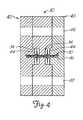
- the molding surfaceis defined by the inner surface of the forming port, the inner surfaces of the central recess 34 and the faces of the compression disks 44 which are received within the recesses 34. If an internal molding section is used, the cylindrical outer surface of that section may also be considered a part of the molding surface of the molding element 20. Accordingly, when the molding element 20 is completely assembled the metal fabric will tend to assume a somewhat "dumbbell"-shaped configuration, with a relatively narrow center section disposed between a pair of bulbous, perhaps even disk-shaped end sections, as best seen in Figure 4.
- the specific shape of the particular molding element 20 shown in Figures 2-4is intended to produce one useful medical device in accordance with the present method, but that other molding elements having different configurations could also be used. If a more complex shape is desired, the molding element may have more parts, but if a simpler shape is being formed the molding element may have even fewer parts. The number of parts in a given molding element and the shapes of those parts will be dictated almost entirely by the shape of the desired medical device as the molding element must define a molding surface to which the metal fabric will generally conform.
- the specific molding element 20 shown in Figures 2-4is simply intended as one specific example of a suitable molding element for forming one particular useful medical device. Additional molding elements having different designs for producing different medical devices are explained below in connection with, e.g., Figures 8 and 10. Depending on the desired shape of the medical device being formed, the shape and configuration of other specific molding elements can be readily designed by those of ordinary skill in the art.
- the fabriccan be subjected to a heat treatment while it remains in contact with that molding surface.
- This heat treatmentwill depend in large part upon the material of which the wire strands of the metal fabric are formed, but the time and temperature of the heat treatment should be selected to substantially set the fabric in its deformed state, i.e., wherein the wire strands are in their reoriented relative configuration and the fabric generally conforms to the molding surface.
- the time and temperature of the heat treatmentcan vary greatly depending upon the material used in forming the wire strands.
- one preferred class of materials for forming the wire standsare shape memory alloys, with nitinol, a nickel titanium alloy, being particularly preferred. If nitinol is used in making the wire strands of the fabric, the wire strands will tend to be very elastic when the metal is in its austenitic phase; this very elastic phase is frequently referred to as a "superelastic" or "pseudoelastic” phase.
- the crystal structure of the nitinol metal when in its austenitic phasecan be set. This will tend to "set" the shape of the fabric and the relative configuration of the wire strands in the positions in which they are held during the heat treatment.
- nitinol wireto set a desired shape
- Spirally wound nitinol coilsfor example, are used in a number of medical applications, such as in forming the coils commonly carried around distal lengths of guidewires.
- a wide body of knowledgeexists for forming nitinol in such medical devices, so there is no need to go into great detail here on the parameters of a heat treatment for the nitinol fabric preferred for use in the present invention.
- FIG. 5A and 5Billustrate one embodiment of a medical device 60 which may be made using the molding element 20 of Figures 2-4. As discussed below, the device of Figure 5 is particularly well suited for use in occluding a channel within a patient's body and these designs have particular advantages in use as vascular occlusion devices.
- the vascular occlusion device 60 of Figure 5Aincludes a generally tubular middle portion 62 and a pair of expanded diameter portions 64.
- One expanded diameter portionis disposed at either end of the generally tubular middle portion 62.
- the expanded diameter portions 64include a ridge 66 positioned about midway along their lengths.
- the medical deviceis intended to be used as a vascular occlusion device to substantially stop the flow of blood through a patient's blood vessel.
- the device 60When the device 60 is deployed within a patient's blood vessel, as detailed below, it will be positioned within the vessel such that its axis generally coincides with the axis of the vessel.
- the dumbbell-shape of the present deviceis intended to limit the ability of the vascular occlusion device 60 to turn at an angle with respect to the axis of the blood vessel to ensure that it remains in substantially the same position in which the operator deploys it within the vessel.
- each expanded diameter portionis separated from at least one other expanded diameter portion by a tubular portion having a smaller diameter. If so desired, the diameters of each of the expanded diameter portions can be the same, but they need not be the same.
- the maximum diameter of the expanded diameter portions 64(which occurs along the middle ridge 66 in this embodiment) should be selected so that it is at least as great as the diameter of the lumen of the vessel in which it is to be deployed, and is optimally slightly greater than that diameter.
- the vascular occlusion device 60When it is deployed within the patient's vessel, the vascular occlusion device 60 will engage the lumen at two spaced-apart locations.
- the device 60is desirably longer along its axis than the dimension of its greatest diameter. This will substantially prevent the vascular occlusion device 60 from turning within the lumen at an angle to its axis, essentially preventing the device from becoming dislodged and tumbling along the vessel with blood flowing through the vessel.
- the relative sizes of the generally tubular middle portion 62 and expanded diameter portion 64 of the vascular occlusion device 60can be varied as desired for any particular application.
- the outer diameter of the middle portion 62may range between about one quarter and about one third of the maximum diameter of the expanded diameter portions 64 and the length of the middle portion 62 may comprise about 20% to about 50% of the overall length of the device.
- these dimensionsare suitable if the device 60 is to be used solely for occluding a vascular vessel, it is to be understood that these dimensions may be varied if the device is to be used in other applications, such as where the device is intended to be used simply as a vascular filter rather than to substantially occlude the entire vessel or where the device is deployed in a different channel in a patient's body.
- the aspect ratio (i.e., the ratio of the length of the device over its maximum diameter or width) of the device 60 illustrated in Figures 5A and 5Bis desirably at least about 1.0, with a range of about 1.0 to about 3.0 being preferred and an aspect ratio of about 2.0 being particularly preferred. Having a greater aspect ration will tend to prevent the device from rotating generally perpendicularly to its axis, which may be referred to as an end over end roll.
- the outer diameter of the expanded diameter portions 64 of the deviceis large enough to seat the device fairly securely against the lumen of the channel in which the device is deployed, the inability of the device to turn end over end will help keep the device deployed precisely where it is positioned within the patient's vascular system or in any other channel in the patient's body.
- having expanded diameter portions which have natural, relaxed diameters substantially larger than the lumen of the vessels in which the device is deployedshould also suffice to wedge the device into place in the vessel without undue concern being placed on the aspect ratio of the device.
- the pick and pitch of the metal fabric 10 used in forming the device 60are important in determining a number of the properties of the device. For example, the greater the pick and pitch of the fabric, and hence the greater the density of the wire strands in the fabric, the stiffer the device will be. Having a greater wire density will also provide the device with a greater wire surface area, which will generally enhance the tendency of the device to occlude a blood vessel in which it is deployed.
- This thrombogenicitycan be either enhanced, e.g. by a coating of a thrombolytic agent or by attaching silk or wool fabric to the device, or abated, e.g. by a coating of a lubricious, anti-thrombogenic compound.
- a variety of materials and techniques for enhancing or reducing thrombogenicityare well known in the art and need not be detailed here.
- thrombiWhen the device is deployed in a patient's vessel, thrombi will tend to collect on the surface of the wires. By having a greater wire density, the total surface area of the wires will be increased, increasing the thrombolytic activity of the device and permitting it to relatively rapidly occlude the vessel in which it is deployed. It is believed that forming the occlusion device 60 from a 4 mm diameter tubular braid having a pick of at least about 40 and a pitch of at least about 30° will provide sufficient surface area to substantially completely occlude a blood vessel of 2 mm to about 4 mm in inner diameter in a suitable period of time. If it is desired to increase the rate at which the device 60 occludes the vessel in which it is deployed, any of a wide variety of known thrombolytic agents can be applied to the device.
- FIGS 6A-6Cillustrate an alternative embodiment of a medical device in accordance with the present invention.
- This device 80has a generally bell-shaped body 82 and an outwardly extending forward end 84.
- One application for which this device is particularly well suitedis occluding defects known in the art as patent ductus arteriosus (PDA).
- PDAis essentially a condition wherein two blood vessels, most commonly the aorta and pulmonary artery adjacent the heart, have a shunt between their lumens. Blood can flow directly between these two blood vessels through the shunt, compromising the normal flow of blood through the patient's vessels.
- the bell-shaped body 82is adapted to be deployed within the shunt between the vessels, while the forward end 84 is adapted to be positioned within one of the two vessels to help seat the body in the shunt.
- the sizes of the body 82 and the end 84can be varied as desired for differently sized shunts.
- the bodymay have a diameter along its generally cylindrical middle 86 of about 10 mm and a length along its axis of about 25 mm.
- the base 88 of the bodymay flare generally radially outward until it reaches an outer diameter equal to that of the forward end 84, which may be on the order of about 20 mm in diameter.
- the base 88desirably flares out relatively rapidly to define a shoulder tapering radially outwardly from the middle 86 of the body. When the device is deployed in a vessel, this shoulder will abut the lumen of one of the vessels being treated.
- the forward end 84is retained within the vessel and urges the base 88 of the body open to ensure that the shoulder engages the wall of the vessel to prevent the device 80 from becoming dislodged from within the shunt.
- a clamp 15is used to tie together the ends of the wire strands adjacent the front end 84 of the device. It is to be understood that this clamp 15 is simply a schematic illustration, though, and that the ends could be attached in other ways, such as by welding, soldering, brazing, use of a biocompatible cementitious material or in any other suitable fashion.
- the rearward ends of the wire strandsare shown as being attached to one another by an alternative clamping means 90.
- This clamp 90serves the same purpose as the schematically illustrated clamp 15, namely to interconnect the ends of the wires. However the clamp 90 also serves to connect the device 80 to a delivery system (not shown).
- the clamp 90is generally cylindrical in shape and has a recess for receiving the ends of the wires to substantially prevent the wires from moving relative to one another, and a threaded outer surface.
- the threaded outer surfaceis adapted to be received within a cylindrical recess (not shown) on a distal end of a delivery device and to engage the threaded inner surface of the delivery device's recess.
- the delivery device(not shown) can take any suitable shape, but desirably comprises an elongate, flexible metal shaft having such a recess at its distal end.
- the delivery devicecan be used to urge the PDA occlusion device 80 through the lumen of a catheter for deployment in a channel of the patient's body, as outlined below. When the device is deployed out the distal end of the catheter, the device will still be retained by the delivery device. Once the proper position of the device 80 in the shunt is confirmed, the shaft of the delivery device can be rotated about its axis to unscrew the clamp 90 from the recess in the delivery means.
- the operatorcould still retract the device for repositioning if it is determined that the device is not properly positioned in the first attempt.
- This threaded attachmentwill also allow the operator to control the manner in which the device 80 is deployed out of the distal end of the catheter. As explained below, when the device exits the catheter it will tend to resiliently return to a preferred expanded shape which is set when the fabric is heat treated. When the device springs back into this shape, it may tend to act against the distal end of the catheter, effectively urging itself forward beyond the end of the catheter. This spring action could conceivably result in improper positioning of the device if the location of the device within a channel is critical, such as where it is being positioned in a shunt between two vessels. Since the threaded clamp 90 can enable the operator to maintain a hold on the device during deployment, the spring action of the device can be controlled and the operator can control the deployment to ensure proper positioning.
- a PDA occlusion device 80 of this embodiment of the inventioncan advantageously be made in accordance with the method outlined above, namely deforming a metal fabric to generally conform to a molding surface of a molding element and heat treating the fabric to substantially set the fabric in its deformed state.
- Figure 7shows a molding element 100 which may be suitable for forming a PDA occlusion device 80 such as that shown in Figures 6A-6C.
- the molding element 100generally comprises a body portion 110 and an end plate 120.
- the body portion 110is adapted to receive and form the body 82 of the device 80 while the end plate is adapted to compress against the metal fabric to form the forward end 84.
- the body portion 110includes an elongate, generally tubular central segment 112 which is sized to receive the elongate body 82 of the device.
- the central segment 112 of the molding element 100optimally has an internal diameter slightly less than the natural, relaxed outer diameter of the tubular braid of which the device is formed. This compression of the braid will help yield devices with reproducibly sized bodies 82.
- the forward end of the body portion 110includes a back plate 114 which has a generally annular sidewall 116 depending downwardly therefrom. The sidewall defines a recess 118 which is generally circular in shape.
- the end plate 120 of the molding element 100has a generally disc-shaped face 122, which desirably has a clamp port 124 approximately centered therein for receiving a clamp 15 attached to the metal fabric, as noted above.
- the end platealso has an annular sidewall 126 which extends generally upwardly from the face 122 to define a generally cylindrical recess 128 in the end plate 120.
- the sidewall 116 of the body portion 110is sized to be received within the recess 128 of the end plate.
- the metal fabricis placed in the molding element and the body portion 110 and the end plate 120 are brought toward one another.
- the inner face of the back plate 114will engage the fabric and tend to urge it under compression generally radially outwardly.
- the fabricwill then be enclosed generally within the recess 118 of the body portion and will generally conform to the inner surface of that recess. If one prevents the entire clamp 15 from passing through the clamp port 124, the fabric will be spaced slightly away from the inner surface of the face 122, yielding a slight dome shape in the forward end 84 of the device, as illustrated in Figures 6.
- the illustrated embodimentincludes such a dome-shaped forward end, it is to be understood that the forward end may be substantially flat (except for the clamp 15), which can be accomplished by allowing the clamp to be received entirely within the clamp port 124 in the end plate.
- the fabriccan be subjected to a heat treatment such as is outlined above.
- a heat treatmentsuch as is outlined above.
- the devicecan then be collapsed, such as by urging the clamps 15, 90 generally axially away from one another, which will tend to collapse the device toward its axis.
- the collapsed device 80can then be passed through a catheter for deployment in a channel in a patient's vascular system.
- FIG 8schematically illustrates how a medical device 80 generally as outlined above can be used to occlude a patent ductus arteriosus.
- a shuntreferred to as a PDA above, which extends between a patient's aorta A and the pulmonary artery P.
- the device 80can be passed through the PDA, such as by keeping the device collapsed within a catheter (not shown), and the forward end 84 of the device can be allowed to elastically expand to substantially recover its thermally set, "remembered" shape from the heat treatment process, such as by urging the device distally to extend beyond the distal end of the catheter.
- This forward end 84should be larger than the lumen of the shunt of the PDA.
- the devicecan then be retracted so that the forward end 84 engages the wall of the pulmonary artery P. If one continues to retract the catheter, the engagement of the device with the wall of the pulmonary artery will tend to naturally pull the body portion 82 of the device from the catheter, which will permit the body portion to return to its expanded configuration.
- the body portionshould be sized so that it will frictionally engage the lumen of the PDA's shunt.
- the device 80will then be held in place by the combination of the friction between the body portion and the lumen of the shunt and the engagement between the wall of the pulmonary artery and the forward end 84 of the device. Over a relatively short period of time, thrombi will form in and on the device 80 and the thrombi will occlude the PDA. If so desired, the device may be coated with a suitable thrombolytic agent to speed up the occlusion of the PDA.
- FIGS 9A and 9Bare a side view and an end view, respectively, of yet another embodiment of the present invention.
- This device 180can be used for a variety of applications in a patient's blood vessels. For example, if a fabric having a relatively high pick (i.e. where the wire density is fairly great) is used in making the device, the device can be used to occlude blood vessels. In other applications, it may serve as a filter within a channel of a patient's body, either in a blood vessel or in another channel, such as in a urinary tract or biliary duct. In order to further enhance or reduce the device's tendency to occlude the vessel, depending on the application of the device a suitable known thrombogenic or antithrombogenic coating may be applied to the device.
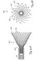
- This filter 180has a generally conical configuration, tapering generally radially outwardly from its rearward end 182 to its forward end 184. A length of the device adjacent its forward end is adapted to engage the walls of a lumen of a channel. The maximum diameter of the filter device 180 is therefore at least as large as the inner diameter of the channel in which it is to be positioned so that at least the forward end will engage the wall of the vessel to substantially lock the device in place.
- the method in which the device 180 of the invention is deployedmay vary depending on the nature of the physiological condition to be treated. For example, in treating an arterio-venous fistula, the device may be carefully positioned, as described above, to occlude the flow of blood at a fairly specific location. In treating other conditions (e.g. an arterio-venous malformation), however, if may be desired to simply release a number of these devices upstream of the malformation in a vessel having a larger lumen and simply allow the devices to drift from the treatment site to lodge in smaller vessels downstream.
- other conditionse.g. an arterio-venous malformation
- the decision as to whether the device 180 should be precisely positioned at an exact location within the channel in a patient's body or whether it is more desirable to allow the device(s) to float to their final lodging sitewill depend on the size of the channels involved and the specific condition to be treated. This decision should be left to the individual operator to be made on a case-by-case basis as his or her experience dictates; there is no one right or wrong way to deploy the device 180 without regard to the conditions at hand.
- the wall of the deviceextends generally linearly from a position adjacent the clamp 90 and the other end of the device, approximating a conical shape. Due to the presence of the clamp 90, though, the end of the device immediately adjacent the clamp may deviate slightly from the cone shape, as indicated in the drawings. Alternatively, the wall may be curved so that the diameter of the device changes more rapidly adjacent the rearward end than it does adjacent its forward end, having an appearance more like a rotation of a parabola about its major axis than a true cone. Either of these embodiments should suffice in occluding a vessel with the device 180, such as to occlude a vessel.
- the ends of the wire strands at the rearward end 182 of the deviceare secured with respect to one another, such as by means of a threaded clamp 90 such as that described above in connection with Figures 6A-6C. Portions of the wire strands adjacent the forward end 184 may also be secured against relative movement, such as by spot welding wires to one another where they cross adjacent the forward end. Such a spot weld is schematically illustrated at 186 in Figures 9A and 9B.
- the ends of the wire strands adjacent the forward end 184 in the finished deviceneed not be affixed to one another in any fashion. These strands are held in a fixed position during the forming process to prevent the metal fabric from unraveling before it is made into a finished device. While the ends of the wire strands adjacent the forward end remain fixed relative to one another, they can be heat treated, as outlined above. The heat treatment will tend to fix the shapes of the wires in their deformed configuration wherein the device generally conforms to a molding surface of the molding element. When the device is removed from contact with the molding element, the wires will retain their shape and tend to remain intertwined. Accordingly, when the device is released from contact with the molding element, even if the ends of the wires are released from any constraint the device should still substantially retain its shape.
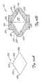
- Figures 10A-10Cillustrate three suitable molds for use in forming the filter 180 of Figures 9A and 9B.
- the molding element 200is a single piece which defines a pair of generally conical portions abutting one another.
- the molding element 200may be generally ovoid, shaped not unlike an American football or a rugby ball.
- the molding elementis a little bit less rounded.
- This molding elementcomprises two conical segments 202 which abut one another at their bases, defining a larger diameter at the middle 204 of the element which can taper relatively uniformly toward the ends 206 of the element 200.
- the tubular metal fabricmay be applied to the molding element by placing the molding element within the tubular braid and clamping the ends of the braid about the molding element before cutting the braid to the desired length.
- the ends 206 of the molding elementmay be rounded, as shown, rather than tapering to a sharper point at the ends of the molding element.
- the natural, relaxed diameter of the braidshould be less than the maximum diameter of the element, which occurs at its middle 204. This will place the metal fabric in tension about the middle of the element and, in combination with the clamps at the ends of the braid, cause the braid to generally conform to the molding surface.
- FIG 10Billustrates an alternative molding element 210 for forming a device substantially as shown in Figures 9A and 9B.
- the molding element 200is intended to be received within a recess in the metal fabric, such as within the lumen of a length of tubular braid
- the molding element 210has an internal cavity 212 adapted to receive the fabric.
- the molding elementmay comprise a pair of molding sections 214, 216 and these mold sections may be substantially identical in shape.
- Each of the molding sections 214, 216generally comprise a conical inner surface 220 defined by a wall 222.
- Each sectionalso may be provided with a generally cylindrical axial recess 224 for receiving a clamp 15 (or 90) carried by an end of the metal fabric.
- the two molding sectionsshould be readily attached to one another with the larger, open ends 226 of the sections abutting one another.
- the mold sectionscan simply be clamped together, such as by providing a reusable jig (not shown) which can be used to properly position the sections 214, 216 with respect to one another.
- bolt holes 228 or the likemay be provided to allow a nut and bolt, or any similar attachment system, to be passed through the holes and attach the sections 214, 216 together.
- a suitably sized piece of a metal fabricis placed in the recess 212 of the molding element and the two molding sections 214, 216 are urged toward one another.
- the fabricshould have a relaxed axial length longer than the axial length of the recess 212 so that bringing the sections toward one another will axially compress the fabric. This axial compression will tend to urge the wire strands of the braid radially outwardly away from the axis of the braid and toward engagement with the molding surface of the element 210, which is defined by the surface of the recess 212.
- the fabriccan be heat treated to substantially set the shape of the fabric in its deformed state. If molding element 200 is used, it can then be removed from the interior of the metal fabric. If there is sufficient room between the resilient wire strands, the molding element can simply be removed by opening the web of wire strands and pulling the molding element out of the interior of the metal fabric. If molding element 210 is employed, the two molding sections 214, 216 can be moved away from one another and the molded fabric can be retrieved from the recess 212. Depending on the shape of the molding surface, the resulting formed shape may resemble either a pair of abutting hollow cones or, as noted above, a football, with clamps, welds or the like provided at either end of the shape.
- This shapecan then be cut into two halves by cutting the wires in a direction generally perpendicular to the shared axis of the cones (or the major axis of the ovoid shape) at a location about midway along its length.
- Thiswill produce two separate filter devices 180 substantially as illustrated in Figures 9A and 9B. If the wires strands are to be joined adjacent the forward end of the device (such as by the weldments shown as 186 in Figures 9A and 9B), this can be done before the conical or ovoid shape is severed into two halves. Much the same net shape could be accomplished by cutting the metal fabric into halves while it is still carried about molding element 200. The separate halves having the desired shape could then be pulled apart from one another, leaving the molding element ready for forming additional devices.
- the molding element 200is formed of a material selected to permit the molding element to be destroyed for removal from the interior of the metal fabric.
- the molding elementmay be formed of a brittle or friable material, such as glass. Once the material has been heat treated in contact with the molding surface of the molding element, the molding element can be broken into smaller pieces which can be readily removed from within the metal fabric. If this material is glass, for example, the molding element and the metal fabric can be struck against a hard surface, causing the glass to shatter. The glass shards can then be removed from the enclosure of the metal fabric.
- the resultant shapecan be used in its generally conical shape, or it can be cut into two separate halves to produce a device substantially as shown in Figures 9A and 9B.
- the molding element 200can be formed of a material which can be chemically dissolved, or otherwise broken down, by a chemical agent which will not substantially adversely affect the properties of the metal wire strands.
- the molding elementcan be formed of a temperature-resistant plastic resin which is capable of being dissolved with a suitable organic solvent.
- the fabric and the molding elementcan be subjected to a heat treatment to substantially set the shape of the fabric in conformance with the surface of the molding element, whereupon the molding element and the metal fabric can be immersed in the solvent. Once the molding element is substantially dissolved, the metal fabric can be removed and either used in its current shape or cut into separate halves, as outlined above.
- the molding elementcould be formed of a material having a melting point above the temperature necessary to set the shape of the wire strands, but below the melting point of the metal forming the strands.
- the molding element and metal fabriccan then be heat treated to set the shape of the metal fabric, whereupon the temperature can be increased to substantially completely melt the molding element, thereby removing the molding element from within the metal fabric.
- the methods outlined immediately above for removing the metal fabric 10 from the molding element 200can be used in connection with other shapes, as well. Although these methods may not be necessary or desirable if the molding element is carried about the exterior of the metal fabric (such as are elements 30-40 of the molding element 20 of Figures 2-4), if the molding element or some portion thereof is enclosed within the formed metal fabric (such as the internal molding section of the molding element 20), these methods can be used to effectively remove the molding element without adversely affecting the medical device being formed.
- FIG 10Cillustrates yet another molding element 230 which can be used in forming a medical device such as that illustrated in Figures 9A and 9B.
- This molding elementcomprises an outer molding section 232 defining a tapered inner surface 234 and an inner molding section 236 having an outer surface 238 substantially the same shape as the tapered inner surface 234 of the outer molding section.
- the inner molding section 236should be sized to be received within the outer molding section, with a piece of the metal fabric (not shown) being disposed between the inner and outer molding sections.
- the molding surface of this molding element 230, to which the fabric will generally conform,can be considered to include both the inner surface 234 of the outer molding section and the outer surface 238 of the inner molding section.
- This molding element 230can be used with a metal fabric which is in the form of a tubular braid. If such a fabric is used and a clamp 15 (not shown in this drawing) or the like is provided to connect the ends of the wire strands adjacent one end of the device, a recess (not shown) analogous to the cavity 46 in the face of the compression disk 44 of molding element 20 ( Figures 2-4) can be provided for receiving the clamp.
- the present molding element 230can be used quite readily with a flat woven piece of metal fabric, such as is illustrated in Figure 1B.
- a suitably sized and shaped piece of fabricis cut; in using the molding element 230 to produce a device 180 analogous to that shown in Figures 9A and 9B, for example, a generally disk-shaped piece of the metal fabric 10' can be used.
- the metal fabricis then placed between the two sections 232, 236 of the molding element and the sections are moved together to deform the fabric therebetween. After heat treatment, the fabric can be removed and will retain substantially the same shape as it had when it was deformed between the two molding sections.
- molding elements 200, 210 and 230 in Figures 10A-10Cmay achieve essentially the same desired shape. These molding elements may be received entirely within a closed segment of fabric and rely on tension and/or compression of the fabric to cause it to generally conform to the molding surface of the molding element, as with the element 200 of Figure 10A.
- the molding element 210 of Figure 10Bsubstantially encloses the fabric within a recess in the mold and relies on compression of the fabric (in this case axial compression of a tubular braid) to deform the fabric to the desired configuration.
- the fabricmay be compressed between two coacting parts of the molding element to deform the fabric, such as between the two sections 232, 236 of molding element 230 in Figure 10C. Any one or more of these techniques may be used in achieving a finished product having a desired shape.
- Figures 11 and 12illustrate alternative embodiments of yet another medical device in accordance with this invention.
- Both Figure 11 and Figure 12illustrate a vascular trap suitable for use in temporarily filtering embolic particles from blood passing through a patient's vascular system.
- a vascular trapsuitable for use in temporarily filtering embolic particles from blood passing through a patient's vascular system.
- Such a devicewill most frequently be used to filter emboli from a patient's blood when another medical procedure is being performed, such as by using the trap in conjunction with a rotating cutting blade during an atherectomy or with a balloon catheter during angioplasty.
- the trapcould also be used in other similar applications, such as in channels in patients' bodies other than their vascular systems.
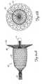
- the vascular trap 250comprises a generally umbrella-shaped basket 270 carried adjacent a distal end of a guidewire 260.
- the guidewire in this embodimentincludes a tapered distal section 262 with a spirally wound coil 264 extending along a distal length of the wire. Guidewires having such a distal end are conventional in the art.
- the basket 270is positioned generally distally of the coil 264, and is desirably attached to the guidewire proximally of the proximal end of the tapered section, as shown.
- the basket 270(shown in its collapsed configuration in Figure 11A) includes a distal band 272 and a proximal band 274.
- the distal bandmay be made of a radiopaque material, such as gold, platinum or tungsten, and is affixed directly to the shaft of the guidewire 260. This attachment may be made by any suitable means, such as by welding, brazing or soldering.
- the distal band 272may comprise a bead of a biocompatible cementitious material, such as a curable organic resin. If it is desired to increase the visibility of the band for fluoroscopic observation, a radiopaque metal or the like can be imbedded in the cementitious material.
- the proximal band 274may be formed of a hypotube sized to permit the tube to slide along the guidewire during deployment.
- This hypotubemay be made of a metallic material; a thin-walled tube of a NiTi alloy should suffice. If so desired, the proximal band may be formed of a more radiopaque metal, or a NiTi alloy band can have a radiopaque coating applied to its surface.
- the body of the deviceis formed of a metal fabric, as explained above.
- the metal fabric of this embodimentis optimally initially formed as a tubular braid and the ends of the wires forming the braid can be attached together by means of the bands 272, 274 before the fabric is cut to length. Much like the clamps 15, 90 noted above, these bands 272, 274 will help prevent the metal fabric from unravelling during the forming process. (The method of forming the basket 270 is described below in connection with Figure 16.)
- the basket 270When the device is in its collapsed state for deployment in a patient's vessel (as illustrated in Figure 11A), the basket 270 will be collapsed toward the axis of the guidewire 260.
- the distal 272 and proximal 274 bandsare spaced away from one another along the length of the guidewire, with the fabric of the device extending therebetween.
- the basketwhen the basket is in its collapsed state it will engage the outer surface of the guidewire to permit the device to be deployed through a relatively small lumen of a catheter or another medical device.
- the basketWhen the device is deployed in a patient's vascular system, the basket will take on an expanded configuration wherein it extends outwardly of the outer surface of the guidewire.
- the shape of the basket 270 when deployedmay generally resemble a conventional umbrella or parachute, having a dome-like structure curving radially outwardly from the guidewire moving proximally from the distal band 272. It is to be understood that other suitable shapes could easily perform the desired filtering function, such as a conical shape wherein the slope of the device changes more linearly than the smooth, rounded version shown in Figure 11B. It is also believed that a relatively flat, disc shape would also suffice.
- the two bands 272, 274are closer together, with the distal band 272 optimally being spaced only a short distance from the proximal band 274, as illustrated.
- the metal fabricturns in on itself, with a proximal portion 282 of the collapsed basket being received within the interior of a distal portion 284 of the collapsed basket.
- the precise dimensions of the metal fabriccan be varied as desired for various applications.
- the pores (i.e. the openings between the crossing metal strands) of the fabricare desirably on the order of about 1.0 mm. This is generally deemed to be the minimum size of any particles which are likely to cause any adverse side effects if they are allowed to float freely within a blood vessel.
- the basketmay be coated with a suitable anti-thrombogenic coating to prevent the basket from occluding a blood vessel in which it is deployed.
- the forming processwill reorient the wires relative to one another and in some areas (e.g. adjacent the proximal lip 286) the pores will be larger than 1.0 mm.
- the basket's wallsare formed of essentially two thicknesses 282, 284 of the fabric, the effective pore size of the device may be significantly reduced even at these locations.
- the device 250may also be provided with tethers 290 for collapsing the basket 270 during retraction.
- the basketmay include four independent tether wires, each of which extends proximally from the proximal lip 286 of the deployed basket.
- the four tether wires illustrated in the drawingsare actually formed of two longer wires, with each wire extending peripherally about a portion of the proximal lip of the basket. These tether wires may be intertwined with the wires of the metal fabric to keep the tethers in place during use.
- the wires extending along the proximal lip of the basketwill tend to act as drawstrings, drawing the proximal end of the basket radially inwardly toward the guidewire. This will tend to close the basket and entrap any material caught in the cavity 288 of the basket during use so that the basket can be retracted, as detailed below.
- the tether wires 290may extend along much of the length of the guidewire so that they will extend outside the patient's body during use of the device 250.
- the operatorcan simply hold the guidewire 260 steady and retract the tethers with respect to the guidewire. This can tend to be relatively cumbersome, though, and may be too difficult to effectively accomplish without breaking the tethers if the device is deployed at a selective site reached by a tortuous path, such as in the brain.
- the tethers 290are attached to the guidewire 260 at a position spaced proximally of the basket.
- the tethersmay, for example, be attached to a metal strap 292 or the like and this strap 292 may be affixed to the shaft of the guidewire.
- an external catheter(not shown) can be urged distally toward the basket 270.
- the catheterencounters the radially extending tethers, the distal end of the catheter will tend to draw the tethers toward the guidewire as the catheter is advanced, which will, in turn, tend to draw the proximal end of the basket closed.
- Figures 12A and 12Billustrate an alternative embodiment of the device shown in Figures 11A and 11B, with Figure 12A showing the device collapsed in a catheter C for deployment and Figure 12B showing the device in its deployed configuration.
- the basket 270is formed substantially the same as outlined above in connection with Figures 11A and 11B.
- the distal band 272is affixed to the guidewire 260' at the distal tip of the guidewire.
- the guidewire 260'is of the type referred to in the art as a "movable core" guidewire.
- a core wire 265is received within the lumen of a helically wound wire coil 266 and the core wire 265 extends distally beyond the distal end of the coil 266.
- a thin, elongate safety wire 268may extend along the entire lumen of the coil 266 and the distal end of the safety wire may be attached to the distal end of the coil to prevent loss of a segment of the coil if the coil should break.
- the proximal ends of the tethers 290are attached to a metal strap 292 which is itself attached the shaft of the guidewire 260.
- the tethersare not attached to the core wire 265 itself. Instead, the tethers are attached to the coil 266 of the guidewire.
- the tethersmay be attached to the coil by any suitable means, such as by means of laser spot welding, soldering or brazing.
- the tethers 290may be attached to the coil 266 at virtually an spot along the length of the coil. As illustrated in these drawings, for example, the tethers may be attached to the coil adjacent the coil's distal end. However, if so desired the tethers may be attached to the coil at a location space more proximally from the basket 270.
- FIG. 12A and 12BAn external catheter such as that referred to in the discussion of Figures 11A, but not shown in those drawings, is illustrated in Figures 12A and 12B.
- the external catheter Ccan be urged distally toward the basket 270.
- the tetherswill tend to be drawn into the distal end of the catheter, which is substantially narrower than the proximal lip 286 of the basket. This will tend to draw the tethers down toward the guidewire and help close the basket, as explained above.
- FIGs 13-15illustrate yet another alternative embodiment of a vascular trap in accordance with the present invention.
- This vascular trap 300includes a basket 320 received over a guidewire 310.
- the basket 320is directly analogous to the basket 270 illustrated in Figures 11-12.
- the basket 320includes a proximal band 322 and a distal band 324.
- the distal bandmay be attached to the guidewire adjacent its distal end. If so desired, though, a structure such as is shown in Figures 11, wherein the guidewire extends distally beyond the basket, could instead be used.
- the basketAs best seen in its collapsed state (shown in Figure 12A), the basket includes a distal segment 325 and a proximal segment 326, with the distal end of the distal segment being attached to the distal band 324 and the proximal end of the proximal segment being attached to the proximal band 322.
- the proximal segment 326When the basket 320 is in it expanded configuration (shown in Figure 12B), the proximal segment 326 is received within the distal segment 325, defining a proximal lip 328 at the proximal edge of the device.
- the wall of the basketthus formed also includes a cavity 329 for trapping solids entrained in a fluid, such as emboli in a patient's blood stream.
- the basket 320 of Figures 13-15is also shaped a little bit differently than the basket 270 of the previous drawings.
- the primary difference between these two basketsis that the basket 320 is a little bit shorter along its axis that is the basket 270.
- This different basket shapeis simply intended to illustrate that the basket of a vascular trap in accordance with the invention can have any of a wide variety of shapes and no particular significance should be attached to the slightly different shapes shown in the various drawings.
- the trap 300includes a basket cover 340 positioned proximally of the basket 320.
- the basket covermay also be formed of a metallic tubular braid and is also adapted to be collapsed to lay generally along the outer surface of the guidewire 310.
- the cover 340is not directly affixed to the guidewire at any point, though, but is instead intended to be slidable along the guidewire.
- the cover 340includes a distal hypotube 342 and a proximal control hypotube 344, with the distal hypotube being attached to the distal end of the cover 340 and the proximal control hypotube 344 being attached to the proximal end of the cover.
- the cover 340is shown in its deployed, expanded configuration in Figure 15. As shown in that figure, the cover has a similar structure to that of the basket 320, but is oriented to be open distally rather that proximally, as is the basket. As best seen in Figures 13 and 14 wherein the cover is in its collapsed state, the cover has a distal segment 352 and a proximal segment 354. When the cover is deployed by urging it distally out of the distal end of the deployment catheter C, the cover 340 will tend to resiliently return to its expanded configuration and the distal hypotube 342 will slide axially proximally along the guidewire toward the proximal control hypotube 344. This will invert the collapsed cover so that the distal section 352 is generally received within the proximal section 354, defining a distal lip 358 of the cover.
- the proximal control hypotube 344may extend along a substantial portion of the length of the catheter 310 so that it extends out of the patient's body when the device 300 is in place.
- an operatorcan control the position of the cover 340 with respect to the basket 320, which is affixed to the guidewires.
- the cover 340may be deployed and the trap may be drawn proximally toward the cover by moving the guidewire proximally with respect to the control hypotube 344.
- the inner diameter of the distal lip 358 of the coveris desirably slightly larger than the outer diameter of the proximal lip 328 of the basket. Hence, when the basket is drawn proximally toward the cover it will be substantially enclosed therein. The cover will therefore tend to trap any emboli (not shown) or other particulate matter retained within the cavity 330 of the basket. A retrieval sheath S may then be urged distally to engage the outer surface of the cover 340. This will tend to cause the cover to collapse about the basket, tightly engaging the outer surface of the basket. This somewhat collapsed structure can then be withdrawn from the patient's channel and removed from the patient's body. By enclosing the basket within the cover, the likelihood of any filtered debris within the basket being lost as the basket is retrieved will be substantially eliminated.
- the guidewire and the metal fabriccan be of any diameter suitable for the intended application of the vascular trap 250, 250' or 300.
- the guidewireis between about 0.014" and about 0.038" in diameter and the wires of the metal fabric used to form the basket (and the cover 340, if a cover is included) are between about 0.002" and about 0.006".
- the thickness of the metal bands (272, 274 or 322, 324)also is desirably in the range of about 0.002"-0.006".
- the guidewirehas an outer diameter of about 0.014" and the wires of the metal fabric are about 0.002" in diameter.
- the metal bands in this embodimentmay also have a thickness of about 0.002" so that they will not be substantially wider than the collapsed basket.
- the deviceWhen the device is collapsed for deployment through a catheter, it will have an outer diameter of about 0.018", permitting the device to be used with catheters and other instruments adapted for use with a 0.018" guidewire.
- Figure 16illustrates one embodiment of a molding element 370 which may be used in making a basket 270.
- a molding element 370which may be used in making a basket 270.
- the basket 320 and cover 340 of the trap 300are shaped somewhat differently, an analogous molding element can be used for these portions of the trap 300 as well by simply modifying some of the dimensions of the molding element 370, but retaining the basic shape and structure of the molding element.
- the molding element 370is merely one possible molding element for forming a shape such as that of the basket 270 and that any one of a variety of different molding elements will be apparent to those skilled in the art, as noted above in connection with Figures 10A-C.
- the molding element 370has an outer molding section 372 defining a curved inner surface 374 and an inner molding section 376 having an outer surface 378 substantially the same shape as the curved inner surface 374 of the outer molding section.
- the inner molding section 376should be sized to be received within the outer molding section, with a piece of the metal fabric (not shown) being disposed between the inner and outer molding sections.
- the inner surface 374 of the outer molding element and the outer surface 378 of the inner molding sectioneach include a recess (375 and 379, respectively) for receiving an end of the braid.
- the molding surface of this molding element 370, to which the fabric will generally conform,can be considered to include both the inner surface 374 of the outer molding section and the outer surface 378 of the inner molding section.
- the two molding sections 372, 376are spaced apart from one another and a length of a tubular braid of metal fabric (not shown in Figure 16) is disposed between these molding sections.
- a tubular braid of metal fabric(not shown in Figure 16) is disposed between these molding sections.
- one end of the fabricis placed in the recess 375 of the outer molding section and the other end of the fabric is placed in the recess 379 in the inner molding section.
- the inner and outer molding sectionscan then be urged generally toward one another.
- the tubular braidwill tend to invert upon itself and a surface of the tubular braid will generally conform to either the inner surface 374 of the outer molding section or the outer surface 378 of the inner molding section, arriving at a shape analogous to that of the basket 270 of the traps 250, 250'.
- the two molding sectionscan them be locked in place with respect to one another and the metal fabric may be heat treated to set the wires in this deformed configuration.
- the method in accordance with the present inventionfurther includes a method of treating a physiological condition of a patient.
- a medical device suitable for treating the conditionwhich may be substantially in accordance with one of the embodiments outlined above, is selected.
- the PDA occlusion device 80 of Figures 6A-6Ccan be selected.
- a cathetermay be positioned within a channel in patient's body to place the distal end of the catheter adjacent the desired treatment site, such as immediately adjacent (or even within) the shunt of the PDA.
- Medical devices made in accordance with the method of the invention outlined abovehave a preset expanded configuration and a collapsed configuration which allows the device to be passed through a catheter.
- the expanded configurationis generally defined by the shape of the medical fabric when it is deformed to generally conform to the molding surface of the molding element. Heat treating the metal fabric substantially sets the shapes of the wire strands in the reoriented relative positions when the fabric conforms to the molding surface. When the metal fabric is then removed from the molding element, the fabric may define a medical device in its preset expanded configuration.
- the medical devicecan be collapsed into its collapsed configuration and inserted into the lumen of the catheter.
- the collapsed configuration of the devicemay be of any shape suitable for easy passage through the lumen of a catheter and proper deployment out the distal end of the catheter.
- the devices shown in Figures 5may have a relatively elongated collapsed configuration wherein the devices are stretched along their axes. This collapsed configuration can be achieved simply by stretching the device generally along its axis, e.g. by manually grasping the clamps 15 and pulling them apart, which will tend to collapse the expanded diameter portions 64 of the device 60 inwardly toward the device's axis.
- the PDA occlusion device 80 of Figures 6also operates in much the same fashion and can be collapsed into its collapsed configuration for insertion into the catheter by applying tension generally along the axis of the device.
- these devices 60 and 80are not unlike "Chinese handcuffs", which tend to constrict in diameter under axial tension.
- the medical deviceOnce the medical device is collapsed and inserted into the catheter, it may be urged along the lumen of the catheter toward the distal end of the catheter. This may be accomplished by using a guidewire or the like to abut against the device and urge it along the catheter.
- the deviceWhen the device begins to exit the distal end of the catheter, which is positioned adjacent the desired treatment site, it will tend to resiliently return substantially entirely to its preset expanded configuration.
- Superelastic alloyssuch as nitinol, are particularly useful in this application because of their ability to readily return to a particular configuration after being elastically deformed to a great extent. Hence, simply urging the medical device out of the distal end of the catheter tend to properly deploy the device at the treatment site.
- the device 60 of Figure 5is intended to have a maximum outer diameter in its expanded configuration at least as large as and preferably larger than, the inner diameter of the lumen in which it is to be deployed. If such a device is deployed in a vessel having a small lumen, the lumen will prevent the device from completely returning to its expanded configuration. Nonetheless, the device would be properly deployed because it would engage the inner wall of the lumen to seat the device therein, as detailed above.
- the deviceis to be used to permanently occlude a channel in the patient's body, such as the devices 60 and 80 described above may be, one can simply retract the catheter and remove it from the patient's body. This will leave the medical device deployed in the patient's vascular system so that it may occlude the blood vessel or other channel in the patient's body.
- the medical devicemay be attached to a delivery system in such a manner as to secure the device to the end of the delivery means, such as when the threaded clamp 90 shown in Figures 6 and 9 are attached to a distal end of the delivery means, as explained above. Before removing the catheter in such a system, it may be necessary to detach the medical device from the delivery means before removing the catheter and the delivery means.
- the devices of Figures 11-15may be deployed in much the same fashion outlined above. However, these devices 250, 250' and 300 are advantageously deployed for use in conjunction with another medical device and will most frequently be retracted from the patient's body after use.
- any one of these devicesare suitable for use in conjunction with a balloon angioplasty procedure.
- catheters having inflatable balloons at their endsreferred to as balloon catheters
- balloon cathetersare positioned within a blood vessel so that the balloon is positioned within a stenosis.
- These balloonsare positioned by tracking the balloon catheter along a guidewire or the like; the balloons typically have a central bore therethrough. Once the balloon is properly positioned, it is inflated and urges radially outwardly against the stenosis. This will tend to squeeze the stenosis against the walls of the vessel, improving patency of the vessel.
- a vascular trap 250, 250' or 300 of the inventioncan be used with the balloon catheter.
- the deviceshould be sized to permit it to be passed through the lumen of the particular balloon catheter to be used in the angioplasty.
- the trapis deployed first.
- the basket (270 or 320) of the trapwill be guided to a position located downstream of the desired treatment site through an introduction catheter (e.g. the catheter C in Figures 12-15).
- the basketis then urged distally beyond the end of the catheter, which will permit the basket to resiliently substantially return to its expanded configuration from its collapsed configuration within the catheter.
- the balloon cathetercan be exchanged for the introduction catheter, and the balloon catheter can track the guidewire (260 or 310) of the vascular trap.
- the ballooncan then be positioned within the stenosis and expanded, as outlined above. Once the angioplasty has been completed, the balloon can be deflated again and withdrawn proximally out of the patient.
- the balloon cathetercan be used to perform the same function as performed by the introduction catheter in the preceding embodiment.
- the balloon catheteris positioned in the patient's vessel so that the distal end of the balloon catheter is located downstream of the stenosis.
- the vascular trap (250, 250' or 300) of the inventionis then passed through the lumen of the balloon catheter and the basket is urged out of the distal end of the catheter.
- the basketwill resiliently substantially return to its preferred expanded configuration, whereupon the balloon catheter can be retracted along the shaft of the device's guidewire until the balloon is properly positioned within the stenosis.
- the balloon cathetercan instead be provided with a length of standard catheter extending distally beyond the distal end of the balloon.
- the ballooncan then be positioned within the stenosis and the basket can be urged out of the distal end of the distal extension of the catheter.
- the length of the distal extension of the cathetershould be sufficient to properly position the basket with respect to the balloon when the basket exits the distal end of the catheter. This will eliminate the need to perform the separate step of retracting the balloon into position within the stenosis after the basket is deployed.
- the ballooncan then be expanded, deflated and withdrawn as described above.
- a vascular trap of the inventionfor use in an atherectomy procedure.
- a cutting headis positioned at the distal end of an elongate, hollow shaft and the cutting head has a bore extending therethrough.
- the trapcan be deployed in either of the methods outlined above, but it is anticipated that in most instances the first procedure will be used, i.e. the basket will be deployed with an introduction catheter, which will be removed so that the cutting device can be guided over the guidewire of the vascular trap.
- the device 250, 250' and 300could also be used in other medical procedures in other bodily channels besides a patient's vascular system.
- the proximal lip (288 or 328) of the basketbe at least as large as the lumen of the vessel.
- the natural dimension of the proximal lipi.e. where the basket has fully returned to its expanded configuration
- the vessel's inner diameteris somewhat greater than the vessel's inner diameter so that the basket will firmly engage the wall of the vessel.
- the method of retracting the basketwill depend on which embodiment of the vascular trap is used, namely whether or not the device includes a cover 340.
- the device 250 or 250' of Figures 11 or 12, respectively,do not include such a cover. However, they do include tethers 290 which extend proximally from the proximal lip 288 of the basket to an attachment to the guidewire.
- a retrieval cathetercan be introduced over the guidewire and urged distally toward the basket. As explained above in connection with Figures 11 and 12, this will tend to draw the tethers down toward the guidewire, effectively closing the proximal end of the basket 270.
- the catheter and the vascular trapcan be retracted together from the patient's body.
- any emboli which are captured in the basket when it is deployedcan be retained within the basket until it is removed from the patient's body.
- a balloon catheter or like devicecan instead be used, with the balloon catheter being used to draw down the tethers 290 and collapse the basket.
- the vascular trapcan then be withdrawn with the balloon catheter rather than having to separately introduce a removal catheter to remove the trap.
- the cover 340is positioned over the proximal lip of the basket before the vascular trap 300 is retracted. Once the medical procedure is completed and any debris has been captured in the basket, the cover 340 is allowed to resiliently substantially return to its expanded configuration. Once it is deployed proximally of the basket, the basket 320 can be drawn proximally toward the cover 340 until it engages or is received within the cover, as noted above in connection with Figure 15.
- the cover 340may be unable to return to its full expanded configuration due to the confines of the vessel in which it is deployed.
- the cover 340is desirably larger than the basket 320 so that the basket can be received within the cover.
- the basketis optimally sized to engage the walls of the vessel to prevent the unwanted passage of emboli or other debris around the edges of the basket.
- the distal lip 358 of the coverwill engage the wall of the channel before it expands to its full size.
- the walls of most bodily channels, such as blood vesselstend to be somewhat elastic, though. The cover 340 will therefore tend to urge harder against the wall of the vessel than the smaller basket and may stretch the vessel a little bit more than will the basket.
- the covermay still be able to expand to a dimension large enough to permit the basket to be received in the cavity 356 of the cover. If not, the distal lip 358 of the cover can simply be brought into close engagement with the proximal lip 328 of the basket to generally seal the basket.
- the devicecan be withdrawn proximally from the patient's vascular system.
- the coverwill tend to prevent any emboli caught in the basket during deployment from being inadvertently lost during withdrawal.
- the vascular traps 250, 250' and 300 of the present inventiontherefore have distinct advantages over other vascular traps or filters currently known in the art.
- most prior art trapsare difficult and expensive to form and cannot be readily collapsed for retrieval.
- the present inventionprovides a method for making the vascular traps 250, 250' and 300 which is both relatively inexpensive and less labor intensive, generally resulting in a more consistent product than prior art hand-forming methods.
- the structure of the device and the methods outlined above for removing the devicewill fairly reliably prevent the inadvertent dumping of trapped emboli back into the bloodstream while the device is being removed. Since most prior art traps and filters are much more difficult to use and are more likely to dump filtered debris back into the bloodstream, the present invention can be substantially safer than these prior art systems.
Landscapes
- Health & Medical Sciences (AREA)
- Life Sciences & Earth Sciences (AREA)
- Surgery (AREA)
- General Health & Medical Sciences (AREA)
- Engineering & Computer Science (AREA)
- Heart & Thoracic Surgery (AREA)
- Vascular Medicine (AREA)
- Animal Behavior & Ethology (AREA)
- Biomedical Technology (AREA)
- Veterinary Medicine (AREA)
- Public Health (AREA)
- Medical Informatics (AREA)
- Molecular Biology (AREA)
- Nuclear Medicine, Radiotherapy & Molecular Imaging (AREA)
- Reproductive Health (AREA)
- Cardiology (AREA)
- Oral & Maxillofacial Surgery (AREA)
- Transplantation (AREA)
- Mechanical Engineering (AREA)
- Orthopedic Medicine & Surgery (AREA)
- Surgical Instruments (AREA)
- Prostheses (AREA)
- Media Introduction/Drainage Providing Device (AREA)
- Materials For Medical Uses (AREA)
Abstract
Description
Claims (9)
- A system for performing an intravascular procedure at a treatment sitewithin a lumen defined by the wall of a vessel in a patient's vascular systemcomprising:a guidewire;a filter element associated with a distal region of the guidewire, thefilter element having a distal end and being expandable from a collapsedconfiguration when the filter element is restrained to an expandedconfiguration when the filter element is unrestrained; anda balloon catheter suitable for performing an angioplasty procedure,the balloon catheter having a lumen sized to slidably accommodate theguidewire, arranged such that, during use, the guidewire is positioned acrossa region of stenosis within the vessel, the filter is expanded, the balloon isexpanded within the region of stenosis and wherein embolic material isgenerated and captured by the filter element before the expandable filter isremoved from the vessel.
- The system of claim 1, wherein the filter element is self-expanding.
- The system of claim 1 or claim 2, wherein the filter element comprisesnitinol.
- The system of any one of the preceding claims, wherein the filterelement has a shape in the expanded configuration which defines a cavityhaving a proximally facing opening.
- The system of any one of the preceding claims, wherein the filterelement is mounted on the distal region of the guidewire.
- The system of any one of the preceding claims, wherein the guidewirecomprises a solid material.
- The system of any one of the preceding claims, wherein the guidewirecomprises metal.
- The system of any one of the preceding claims, wherein the guidewirecomprises a tapered portion.
- A trap for trapping particulate material entrained in a fluid within achannel of a patient's body,characterised in that the trap comprises aguidewire having a distal end and a basket (270) carried by the guidewire(260) adjacent the distal end, the basket (270) being adapted to strain theparticulate material from fluid passing therethrough and comprising a metalfabric having first and second ends, at least one end of the fabric beingadapted to slide along the guidewire, the metal fabric having a collapsedconfiguration wherein the first and second ends are spaced from one anothera first distance along the guidewire and the metal fabric has a first diameter,and an expanded configuration wherein the first and second ends are spaceda second, shorter distance along the guidewire and the metal fabric has asecond diameter, the first diameter being less than the second diameter.
Priority Applications (2)
| Application Number | Priority Date | Filing Date | Title |
|---|---|---|---|
| EP06076214AEP1716821A3 (en) | 1994-07-08 | 1995-07-10 | Intravascular filtering device |
| EP06076215AEP1695673A3 (en) | 1994-07-08 | 1995-07-10 | Intravascular filtering device |
Applications Claiming Priority (3)
| Application Number | Priority Date | Filing Date | Title |
|---|---|---|---|
| US27242594A | 1994-07-08 | 1994-07-08 | |
| US272425 | 1994-07-08 | ||
| EP95925591AEP0769926B2 (en) | 1994-07-08 | 1995-07-10 | Intravascular filtering device |
Related Parent Applications (2)
| Application Number | Title | Priority Date | Filing Date |
|---|---|---|---|
| EP95925591ADivisionEP0769926B2 (en) | 1994-07-08 | 1995-07-10 | Intravascular filtering device |
| EP95925591.0Division | 1996-01-25 |
Related Child Applications (4)
| Application Number | Title | Priority Date | Filing Date |
|---|---|---|---|
| EP06076215ADivisionEP1695673A3 (en) | 1994-07-08 | 1995-07-10 | Intravascular filtering device |
| EP06076214ADivisionEP1716821A3 (en) | 1994-07-08 | 1995-07-10 | Intravascular filtering device |
| EP06076214.3Division-Into | 2006-06-13 | ||
| EP06076215.0Division-Into | 2006-06-13 |
Publications (3)
| Publication Number | Publication Date |
|---|---|
| EP1221307A2true EP1221307A2 (en) | 2002-07-10 |
| EP1221307A3 EP1221307A3 (en) | 2003-01-15 |
| EP1221307B1 EP1221307B1 (en) | 2010-02-17 |
Family
ID=23039744
Family Applications (5)
| Application Number | Title | Priority Date | Filing Date |
|---|---|---|---|
| EP06076215AWithdrawnEP1695673A3 (en) | 1994-07-08 | 1995-07-10 | Intravascular filtering device |
| EP06076214AWithdrawnEP1716821A3 (en) | 1994-07-08 | 1995-07-10 | Intravascular filtering device |
| EP95925591AExpired - LifetimeEP0769926B2 (en) | 1994-07-08 | 1995-07-10 | Intravascular filtering device |
| EP02076318AExpired - LifetimeEP1221307B1 (en) | 1994-07-08 | 1995-07-10 | System for performing an intravascular procedure |
| EP96905195AExpired - LifetimeEP0902704B1 (en) | 1994-07-08 | 1996-01-24 | Apparatus for occluding aneurysms and method of forming said apparatus |
Family Applications Before (3)
| Application Number | Title | Priority Date | Filing Date |
|---|---|---|---|
| EP06076215AWithdrawnEP1695673A3 (en) | 1994-07-08 | 1995-07-10 | Intravascular filtering device |
| EP06076214AWithdrawnEP1716821A3 (en) | 1994-07-08 | 1995-07-10 | Intravascular filtering device |
| EP95925591AExpired - LifetimeEP0769926B2 (en) | 1994-07-08 | 1995-07-10 | Intravascular filtering device |
Family Applications After (1)
| Application Number | Title | Priority Date | Filing Date |
|---|---|---|---|
| EP96905195AExpired - LifetimeEP0902704B1 (en) | 1994-07-08 | 1996-01-24 | Apparatus for occluding aneurysms and method of forming said apparatus |
Country Status (7)
| Country | Link |
|---|---|
| US (27) | US6605102B1 (en) |
| EP (5) | EP1695673A3 (en) |
| JP (2) | JPH10504738A (en) |
| CA (1) | CA2194671A1 (en) |
| DE (2) | DE69536046D1 (en) |
| ES (3) | ES2340142T3 (en) |
| WO (2) | WO1996001591A1 (en) |
Cited By (7)
| Publication number | Priority date | Publication date | Assignee | Title |
|---|---|---|---|---|
| US9629736B2 (en) | 2006-10-22 | 2017-04-25 | Idev Technologies, Inc. | Secured strand end devices |
| US9925074B2 (en) | 1999-02-01 | 2018-03-27 | Board Of Regents, The University Of Texas System | Plain woven stents |
| CN107920827A (en)* | 2015-08-06 | 2018-04-17 | Kp万科公司 | Axially elongated thrombus capture system |
| US11471175B2 (en) | 2015-08-06 | 2022-10-18 | Vascular Medcure, Inc. | Axial lengthening thrombus capture system |
| US11490913B2 (en) | 2015-08-06 | 2022-11-08 | Vascular Medcure, Inc. | Axial lengthening thrombus capture system |
| US11793531B2 (en) | 2019-11-05 | 2023-10-24 | Vascular Medcure, Inc. | Axial lengthening thrombus capture system, tensioning system and expandable funnel catheter |
| US12226112B1 (en) | 2023-12-15 | 2025-02-18 | Cerebrova KP Medical, Inc. | Neurovascular clot retrieving system |
Families Citing this family (1100)
| Publication number | Priority date | Publication date | Assignee | Title |
|---|---|---|---|---|
| US5713848A (en)* | 1993-05-19 | 1998-02-03 | Dubrul; Will R. | Vibrating catheter |
| ES2340142T3 (en) | 1994-07-08 | 2010-05-31 | Ev3 Inc. | SYSTEM TO CARRY OUT AN INTRAVASCULAR PROCEDURE. |
| WO2000053120A1 (en)* | 1994-07-08 | 2000-09-14 | Microvena Corporation | Minimally invasive medical device deployment and retrieval system |
| US5846261A (en)* | 1994-07-08 | 1998-12-08 | Aga Medical Corp. | Percutaneous catheter directed occlusion devices |
| US5725552A (en)* | 1994-07-08 | 1998-03-10 | Aga Medical Corporation | Percutaneous catheter directed intravascular occlusion devices |
| US6123715A (en)* | 1994-07-08 | 2000-09-26 | Amplatz; Curtis | Method of forming medical devices; intravascular occlusion devices |
| CA2212084C (en) | 1995-02-02 | 2008-11-18 | Boston Scientific Corporation | Surgical wire basket extractor |
| US6348056B1 (en) | 1999-08-06 | 2002-02-19 | Scimed Life Systems, Inc. | Medical retrieval device with releasable retrieval basket |
| US6350266B1 (en) | 1995-02-02 | 2002-02-26 | Scimed Life Systems, Inc. | Hybrid stone retrieval device |
| US6994689B1 (en) | 1995-06-05 | 2006-02-07 | Medtronic Vascular, Inc. | Occlusion of a vessel |
| US6312407B1 (en) | 1995-06-05 | 2001-11-06 | Medtronic Percusurge, Inc. | Occlusion of a vessel |
| US6168604B1 (en)* | 1995-10-06 | 2001-01-02 | Metamorphic Surgical Devices, Llc | Guide wire device for removing solid objects from body canals |
| US6264663B1 (en)* | 1995-10-06 | 2001-07-24 | Metamorphic Surgical Devices, Llc | Device for removing solid objects from body canals, cavities and organs including an invertable basket |
| US6689162B1 (en)* | 1995-10-11 | 2004-02-10 | Boston Scientific Scimed, Inc. | Braided composite prosthesis |
| CN1216929A (en) | 1996-02-02 | 1999-05-19 | 血管转换公司 | Method and apparatus for blocking flow through blood vessels |
| EP1707233A3 (en)* | 1996-02-02 | 2006-12-20 | Medtronic Vascular, Inc. | Apparatus for blocking flow through blood vessels |
| DE19604817C2 (en)* | 1996-02-09 | 2003-06-12 | Pfm Prod Fuer Die Med Ag | Device for closing defect openings in the human or animal body |
| US5733294A (en)* | 1996-02-28 | 1998-03-31 | B. Braun Medical, Inc. | Self expanding cardiovascular occlusion device, method of using and method of making the same |
| US6096053A (en)* | 1996-05-03 | 2000-08-01 | Scimed Life Systems, Inc. | Medical retrieval basket |
| US6800080B1 (en) | 1996-05-03 | 2004-10-05 | Scimed Life Systems, Inc. | Medical retrieval device |
| US5935139A (en)* | 1996-05-03 | 1999-08-10 | Boston Scientific Corporation | System for immobilizing or manipulating an object in a tract |
| SE510577C2 (en)* | 1996-05-08 | 1999-06-07 | Carag Ag | Device for implants |
| US6949116B2 (en) | 1996-05-08 | 2005-09-27 | Carag Ag | Device for plugging an opening such as in a wall of a hollow or tubular organ including biodegradable elements |
| US6270477B1 (en)* | 1996-05-20 | 2001-08-07 | Percusurge, Inc. | Catheter for emboli containment |
| US6652480B1 (en) | 1997-03-06 | 2003-11-25 | Medtronic Ave., Inc. | Methods for reducing distal embolization |
| US6544276B1 (en) | 1996-05-20 | 2003-04-08 | Medtronic Ave. Inc. | Exchange method for emboli containment |
| GB9614950D0 (en)* | 1996-07-16 | 1996-09-04 | Anson Medical Ltd | A ductus stent and delivery catheter |
| US6066158A (en)* | 1996-07-25 | 2000-05-23 | Target Therapeutics, Inc. | Mechanical clot encasing and removal wire |
| US5972019A (en)* | 1996-07-25 | 1999-10-26 | Target Therapeutics, Inc. | Mechanical clot treatment device |
| US6120432A (en) | 1997-04-23 | 2000-09-19 | Vascular Science Inc. | Medical grafting methods and apparatus |
| US5941908A (en)* | 1997-04-23 | 1999-08-24 | Vascular Science, Inc. | Artificial medical graft with a releasable retainer |
| US5976178A (en) | 1996-11-07 | 1999-11-02 | Vascular Science Inc. | Medical grafting methods |
| US6036702A (en) | 1997-04-23 | 2000-03-14 | Vascular Science Inc. | Medical grafting connectors and fasteners |
| US5876367A (en)* | 1996-12-05 | 1999-03-02 | Embol-X, Inc. | Cerebral protection during carotid endarterectomy and downstream vascular protection during other surgeries |
| US6391044B1 (en)* | 1997-02-03 | 2002-05-21 | Angioguard, Inc. | Vascular filter system |
| US5919224A (en)* | 1997-02-12 | 1999-07-06 | Schneider (Usa) Inc | Medical device having a constricted region for occluding fluid flow in a body lumen |
| US6254633B1 (en) | 1997-02-12 | 2001-07-03 | Corvita Corporation | Delivery device for a medical device having a constricted region |
| EP0934092A4 (en)* | 1997-03-06 | 2008-03-26 | Boston Scient Scimed Inc | DEVICE AND METHOD FOR DISTAL PROTECTION |
| US6974469B2 (en) | 1997-03-06 | 2005-12-13 | Scimed Life Systems, Inc. | Distal protection device and method |
| US6152946A (en)* | 1998-03-05 | 2000-11-28 | Scimed Life Systems, Inc. | Distal protection device and method |
| US7094249B1 (en) | 1997-03-06 | 2006-08-22 | Boston Scientific Scimed, Inc. | Distal protection device and method |
| US6026814A (en) | 1997-03-06 | 2000-02-22 | Scimed Life Systems, Inc. | System and method for percutaneous coronary artery bypass |
| US5827324A (en)* | 1997-03-06 | 1998-10-27 | Scimed Life Systems, Inc. | Distal protection device |
| US5814064A (en)* | 1997-03-06 | 1998-09-29 | Scimed Life Systems, Inc. | Distal protection device |
| US6676682B1 (en)* | 1997-05-08 | 2004-01-13 | Scimed Life Systems, Inc. | Percutaneous catheter and guidewire having filter and medical device deployment capabilities |
| US5911734A (en)* | 1997-05-08 | 1999-06-15 | Embol-X, Inc. | Percutaneous catheter and guidewire having filter and medical device deployment capabilities |
| US6761727B1 (en) | 1997-06-02 | 2004-07-13 | Medtronic Ave, Inc. | Filter assembly |
| EP0882428A3 (en)* | 1997-06-05 | 2000-06-14 | Medtronic Ave, Inc. | Intravascular occlusion device |
| US5928260A (en) | 1997-07-10 | 1999-07-27 | Scimed Life Systems, Inc. | Removable occlusion system for aneurysm neck |
| US7569066B2 (en) | 1997-07-10 | 2009-08-04 | Boston Scientific Scimed, Inc. | Methods and devices for the treatment of aneurysms |
| GB9715241D0 (en) | 1997-07-18 | 1997-09-24 | Jeffree Martin A | Device for treating aneurysms |
| EP1006890B1 (en)* | 1997-08-04 | 2006-09-20 | Boston Scientific Limited | Occlusion system for aneurysm repair |
| WO1999008607A1 (en)* | 1997-08-05 | 1999-02-25 | Boston Scientific Limited | Detachable aneurysm neck bridge |
| US6063070A (en)* | 1997-08-05 | 2000-05-16 | Target Therapeutics, Inc. | Detachable aneurysm neck bridge (II) |
| US6086577A (en)* | 1997-08-13 | 2000-07-11 | Scimed Life Systems, Inc. | Detachable aneurysm neck bridge (III) |
| FR2768326B1 (en)* | 1997-09-18 | 1999-10-22 | De Bearn Olivier Despalle | TEMPORARY BLOOD FILTER |
| US6361545B1 (en)* | 1997-09-26 | 2002-03-26 | Cardeon Corporation | Perfusion filter catheter |
| US6066149A (en) | 1997-09-30 | 2000-05-23 | Target Therapeutics, Inc. | Mechanical clot treatment device with distal filter |
| US6183482B1 (en) | 1997-10-01 | 2001-02-06 | Scimed Life Systems, Inc. | Medical retrieval basket with legs shaped to enhance capture and reduce trauma |
| US6099534A (en)* | 1997-10-01 | 2000-08-08 | Scimed Life Systems, Inc. | Releasable basket |
| US6174318B1 (en) | 1998-04-23 | 2001-01-16 | Scimed Life Systems, Inc. | Basket with one or more moveable legs |
| US6371982B2 (en) | 1997-10-09 | 2002-04-16 | St. Jude Medical Cardiovascular Group, Inc. | Graft structures with compliance gradients |
| WO1999022673A1 (en)* | 1997-11-03 | 1999-05-14 | C.R. Bard, Inc. | Temporary vascular filter guide wire |
| US6461370B1 (en) | 1998-11-03 | 2002-10-08 | C. R. Bard, Inc. | Temporary vascular filter guide wire |
| US7491216B2 (en) | 1997-11-07 | 2009-02-17 | Salviac Limited | Filter element with retractable guidewire tip |
| EP1028670B1 (en) | 1997-11-07 | 2008-01-02 | Salviac Limited | An embolic protection device |
| US9498604B2 (en) | 1997-11-12 | 2016-11-22 | Genesis Technologies Llc | Medical device and method |
| DE69839888D1 (en)* | 1997-11-12 | 2008-09-25 | Genesis Technologies Llc | DEVICE FOR REMOVING OCCLUSIONS IN BIOLOGICAL PASSES |
| US20100030256A1 (en) | 1997-11-12 | 2010-02-04 | Genesis Technologies Llc | Medical Devices and Methods |
| US6159165A (en) | 1997-12-05 | 2000-12-12 | Micrus Corporation | Three dimensional spherical micro-coils manufactured from radiopaque nickel-titanium microstrand |
| US6048362A (en)* | 1998-01-12 | 2000-04-11 | St. Jude Medical Cardiovascular Group, Inc. | Fluoroscopically-visible flexible graft structures |
| US7520890B2 (en)* | 1998-01-26 | 2009-04-21 | Phillips Peter W | Reinforced graft and method of deployment |
| US6994713B2 (en) | 1998-01-30 | 2006-02-07 | St. Jude Medical Atg, Inc. | Medical graft connector or plug structures, and methods of making and installing same |
| EP1685808B1 (en) | 1998-01-30 | 2016-09-14 | St.Jude Medical ATG, Inc. | Device for use in closing septal defects and an installation assembly for such device |
| WO1999039648A1 (en) | 1998-02-10 | 1999-08-12 | Dubrul William R | Entrapping apparatus and method for use |
| JP2003522550A (en) | 1998-02-10 | 2003-07-29 | アーテミス・メディカル・インコーポレイテッド | Occlusion, fixation, tensioning, and diverting devices and methods of use |
| US6338709B1 (en) | 1998-02-19 | 2002-01-15 | Medtronic Percusurge, Inc. | Intravascular radiation therapy device and method of use |
| US6235054B1 (en) | 1998-02-27 | 2001-05-22 | St. Jude Medical Cardiovascular Group, Inc. | Grafts with suture connectors |
| US5925060A (en) | 1998-03-13 | 1999-07-20 | B. Braun Celsa | Covered self-expanding vascular occlusion device |
| US5944728A (en)* | 1998-04-23 | 1999-08-31 | Boston Scientific Corporation | Surgical retrieval basket with the ability to capture and release material |
| US6450989B2 (en) | 1998-04-27 | 2002-09-17 | Artemis Medical, Inc. | Dilating and support apparatus with disease inhibitors and methods for use |
| US6015424A (en)* | 1998-04-28 | 2000-01-18 | Microvention, Inc. | Apparatus and method for vascular embolization |
| US6511492B1 (en)* | 1998-05-01 | 2003-01-28 | Microvention, Inc. | Embolectomy catheters and methods for treating stroke and other small vessel thromboembolic disorders |
| US6168615B1 (en) | 1998-05-04 | 2001-01-02 | Micrus Corporation | Method and apparatus for occlusion and reinforcement of aneurysms |
| US6165193A (en) | 1998-07-06 | 2000-12-26 | Microvention, Inc. | Vascular embolization with an expansible implant |
| US7004962B2 (en) | 1998-07-27 | 2006-02-28 | Schneider (Usa), Inc. | Neuroaneurysm occlusion and delivery device and method of using same |
| US6179860B1 (en)* | 1998-08-19 | 2001-01-30 | Artemis Medical, Inc. | Target tissue localization device and method |
| US7410482B2 (en) | 1998-09-04 | 2008-08-12 | Boston Scientific-Scimed, Inc. | Detachable aneurysm neck bridge |
| EP1109499B1 (en) | 1998-09-04 | 2007-08-15 | Boston Scientific Limited | Detachable aneurysm neck closure patch |
| US7314477B1 (en) | 1998-09-25 | 2008-01-01 | C.R. Bard Inc. | Removable embolus blood clot filter and filter delivery unit |
| US7044134B2 (en) | 1999-11-08 | 2006-05-16 | Ev3 Sunnyvale, Inc | Method of implanting a device in the left atrial appendage |
| US6508252B1 (en) | 1998-11-06 | 2003-01-21 | St. Jude Medical Atg, Inc. | Medical grafting methods and apparatus |
| US6652554B1 (en)* | 1999-01-04 | 2003-11-25 | Mark H. Wholey | Instrument for thromboembolic protection |
| CA2360168C (en) | 1999-02-01 | 2008-10-14 | Hideki Hyodoh | Woven bifurcated and trifurcated stents and methods for making the same |
| US6991641B2 (en) | 1999-02-12 | 2006-01-31 | Cordis Corporation | Low profile vascular filter system |
| US20020138094A1 (en)* | 1999-02-12 | 2002-09-26 | Thomas Borillo | Vascular filter system |
| US6171327B1 (en) | 1999-02-24 | 2001-01-09 | Scimed Life Systems, Inc. | Intravascular filter and method |
| US20020169474A1 (en) | 1999-03-08 | 2002-11-14 | Microvena Corporation | Minimally invasive medical device deployment and retrieval system |
| EP1161185A2 (en) | 1999-03-09 | 2001-12-12 | St. Jude Medical Cardiovascular Group, Inc. | Medical grafting methods and apparatus |
| US6632236B2 (en)* | 1999-03-12 | 2003-10-14 | Arteria Medical Science, Inc. | Catheter having radially expandable main body |
| US6231589B1 (en) | 1999-03-22 | 2001-05-15 | Microvena Corporation | Body vessel filter |
| US6277139B1 (en) | 1999-04-01 | 2001-08-21 | Scion Cardio-Vascular, Inc. | Vascular protection and embolic material retriever |
| US6277138B1 (en) | 1999-08-17 | 2001-08-21 | Scion Cardio-Vascular, Inc. | Filter for embolic material mounted on expandable frame |
| US6743247B1 (en) | 1999-04-01 | 2004-06-01 | Scion Cardio-Vascular, Inc. | Locking frame, filter and deployment system |
| US7150756B2 (en) | 1999-04-01 | 2006-12-19 | Scion Cardio-Vascular, Inc | Radiopaque locking frame, filter and flexible end |
| US6537296B2 (en) | 1999-04-01 | 2003-03-25 | Scion Cardio-Vascular, Inc. | Locking frame, filter and deployment system |
| WO2000067666A1 (en) | 1999-05-07 | 2000-11-16 | Salviac Limited | Improved filter element for embolic protection device |
| US7014647B2 (en) | 1999-05-07 | 2006-03-21 | Salviac Limited | Support frame for an embolic protection device |
| US6918921B2 (en) | 1999-05-07 | 2005-07-19 | Salviac Limited | Support frame for an embolic protection device |
| US6964672B2 (en) | 1999-05-07 | 2005-11-15 | Salviac Limited | Support frame for an embolic protection device |
| US6712836B1 (en) | 1999-05-13 | 2004-03-30 | St. Jude Medical Atg, Inc. | Apparatus and methods for closing septal defects and occluding blood flow |
| US6350271B1 (en) | 1999-05-17 | 2002-02-26 | Micrus Corporation | Clot retrieval device |
| US7169154B1 (en) | 1999-05-25 | 2007-01-30 | Scimedlife Systems, Inc. | Releasable basket and method of making thereof |
| US20020169473A1 (en) | 1999-06-02 | 2002-11-14 | Concentric Medical, Inc. | Devices and methods for treating vascular malformations |
| US6375668B1 (en) | 1999-06-02 | 2002-04-23 | Hanson S. Gifford | Devices and methods for treating vascular malformations |
| WO2000072781A2 (en) | 1999-06-02 | 2000-12-07 | Sethel Interventional, Inc. | Intracorporeal occlusive device |
| US6458139B1 (en) | 1999-06-21 | 2002-10-01 | Endovascular Technologies, Inc. | Filter/emboli extractor for use in variable sized blood vessels |
| US6663607B2 (en) | 1999-07-12 | 2003-12-16 | Scimed Life Systems, Inc. | Bioactive aneurysm closure device assembly and kit |
| US20030150821A1 (en) | 1999-07-16 | 2003-08-14 | Bates Mark C. | Emboli filtration system and methods of use |
| US6468291B2 (en) | 1999-07-16 | 2002-10-22 | Baff Llc | Emboli filtration system having integral strut arrangement and methods of use |
| US6530939B1 (en)* | 1999-07-30 | 2003-03-11 | Incept, Llc | Vascular device having articulation region and methods of use |
| EP1207933B1 (en)* | 1999-07-30 | 2011-05-11 | Incept Llc | Vascular filter having articulation region |
| US6544279B1 (en) | 2000-08-09 | 2003-04-08 | Incept, Llc | Vascular device for emboli, thrombus and foreign body removal and methods of use |
| US7229463B2 (en) | 1999-07-30 | 2007-06-12 | Angioguard, Inc. | Vascular filter system for cardiopulmonary bypass |
| JP4439780B2 (en)* | 1999-07-30 | 2010-03-24 | インセプト エルエルシー | Vascular device for removal of emboli, thrombus and foreign bodies |
| US7306618B2 (en) | 1999-07-30 | 2007-12-11 | Incept Llc | Vascular device for emboli and thrombi removal and methods of use |
| US6214026B1 (en) | 1999-07-30 | 2001-04-10 | Incept Llc | Delivery system for a vascular device with articulation region |
| US6179861B1 (en) | 1999-07-30 | 2001-01-30 | Incept Llc | Vascular device having one or more articulation regions and methods of use |
| US6203561B1 (en) | 1999-07-30 | 2001-03-20 | Incept Llc | Integrated vascular device having thrombectomy element and vascular filter and methods of use |
| US7229462B2 (en) | 1999-07-30 | 2007-06-12 | Angioguard, Inc. | Vascular filter system for carotid endarterectomy |
| US7320697B2 (en) | 1999-07-30 | 2008-01-22 | Boston Scientific Scimed, Inc. | One piece loop and coil |
| US6346116B1 (en)* | 1999-08-03 | 2002-02-12 | Medtronic Ave, Inc. | Distal protection device |
| US6142987A (en) | 1999-08-03 | 2000-11-07 | Scimed Life Systems, Inc. | Guided filter with support wire and methods of use |
| US6235044B1 (en) | 1999-08-04 | 2001-05-22 | Scimed Life Systems, Inc. | Percutaneous catheter and guidewire for filtering during ablation of mycardial or vascular tissue |
| US9694121B2 (en) | 1999-08-09 | 2017-07-04 | Cardiokinetix, Inc. | Systems and methods for improving cardiac function |
| US8529430B2 (en) | 2002-08-01 | 2013-09-10 | Cardiokinetix, Inc. | Therapeutic methods and devices following myocardial infarction |
| US8500795B2 (en) | 1999-08-09 | 2013-08-06 | Cardiokinetix, Inc. | Retrievable devices for improving cardiac function |
| US8388672B2 (en) | 1999-08-09 | 2013-03-05 | Cardiokinetix, Inc. | System for improving cardiac function by sealing a partitioning membrane within a ventricle |
| US10307147B2 (en) | 1999-08-09 | 2019-06-04 | Edwards Lifesciences Corporation | System for improving cardiac function by sealing a partitioning membrane within a ventricle |
| US8257428B2 (en)* | 1999-08-09 | 2012-09-04 | Cardiokinetix, Inc. | System for improving cardiac function |
| US7279007B2 (en)* | 1999-08-09 | 2007-10-09 | Cardioklnetix, Inc. | Method for improving cardiac function |
| US20030109770A1 (en) | 1999-08-09 | 2003-06-12 | Sharkey Hugh R. | Device with a porous membrane for improving cardiac function |
| US7674222B2 (en) | 1999-08-09 | 2010-03-09 | Cardiokinetix, Inc. | Cardiac device and methods of use thereof |
| US7582051B2 (en) | 2005-06-10 | 2009-09-01 | Cardiokinetix, Inc. | Peripheral seal for a ventricular partitioning device |
| WO2001015629A1 (en) | 1999-08-27 | 2001-03-08 | Microvena Corporation | Slideable vascular filter |
| US6146404A (en)* | 1999-09-03 | 2000-11-14 | Scimed Life Systems, Inc. | Removable thrombus filter |
| US6368328B1 (en) | 1999-09-16 | 2002-04-09 | Scimed Life Systems, Inc. | Laser-resistant medical retrieval device |
| US7655016B2 (en) | 1999-09-17 | 2010-02-02 | Covidien | Mechanical pump for removal of fragmented matter and methods of manufacture and use |
| US6702830B1 (en) | 1999-09-17 | 2004-03-09 | Bacchus Vascular, Inc. | Mechanical pump for removal of fragmented matter and methods of manufacture and use |
| US6454775B1 (en) | 1999-12-06 | 2002-09-24 | Bacchus Vascular Inc. | Systems and methods for clot disruption and retrieval |
| US6325815B1 (en)* | 1999-09-21 | 2001-12-04 | Microvena Corporation | Temporary vascular filter |
| US8414543B2 (en) | 1999-10-22 | 2013-04-09 | Rex Medical, L.P. | Rotational thrombectomy wire with blocking device |
| US6217589B1 (en) | 1999-10-27 | 2001-04-17 | Scimed Life Systems, Inc. | Retrieval device made of precursor alloy cable and method of manufacturing |
| US6371971B1 (en) | 1999-11-15 | 2002-04-16 | Scimed Life Systems, Inc. | Guidewire filter and methods of use |
| US6623450B1 (en) | 1999-12-17 | 2003-09-23 | Advanced Cardiovascular Systems, Inc. | System for blocking the passage of emboli through a body vessel |
| US6443971B1 (en) | 1999-12-21 | 2002-09-03 | Advanced Cardiovascular Systems, Inc. | System for, and method of, blocking the passage of emboli through a vessel |
| JP2003517870A (en)* | 1999-12-22 | 2003-06-03 | ボストン サイエンティフィック リミテッド | Endovascular occlusion irrigation catheter and its use |
| US6402771B1 (en) | 1999-12-23 | 2002-06-11 | Guidant Endovascular Solutions | Snare |
| US6660021B1 (en) | 1999-12-23 | 2003-12-09 | Advanced Cardiovascular Systems, Inc. | Intravascular device and system |
| US6575997B1 (en) | 1999-12-23 | 2003-06-10 | Endovascular Technologies, Inc. | Embolic basket |
| US6290710B1 (en) | 1999-12-29 | 2001-09-18 | Advanced Cardiovascular Systems, Inc. | Embolic protection device |
| US6702834B1 (en) | 1999-12-30 | 2004-03-09 | Advanced Cardiovascular Systems, Inc. | Embolic protection devices |
| US6540722B1 (en) | 1999-12-30 | 2003-04-01 | Advanced Cardiovascular Systems, Inc. | Embolic protection devices |
| US6511503B1 (en) | 1999-12-30 | 2003-01-28 | Advanced Cardiovascular Systems, Inc. | Catheter apparatus for treating occluded vessels and filtering embolic debris and method of use |
| US7918820B2 (en) | 1999-12-30 | 2011-04-05 | Advanced Cardiovascular Systems, Inc. | Device for, and method of, blocking emboli in vessels such as blood arteries |
| US6695813B1 (en)* | 1999-12-30 | 2004-02-24 | Advanced Cardiovascular Systems, Inc. | Embolic protection devices |
| DE10000137A1 (en)* | 2000-01-04 | 2001-07-12 | Pfm Prod Fuer Die Med Ag | Implantate for closing defect apertures in human or animal bodies, bearing structure of which can be reversed from secondary to primary form by elastic force |
| US6350270B1 (en) | 2000-01-24 | 2002-02-26 | Scimed Life Systems, Inc. | Aneurysm liner |
| US6929633B2 (en) | 2000-01-25 | 2005-08-16 | Bacchus Vascular, Inc. | Apparatus and methods for clot dissolution |
| US6663613B1 (en) | 2000-01-25 | 2003-12-16 | Bacchus Vascular, Inc. | System and methods for clot dissolution |
| US6540768B1 (en) | 2000-02-09 | 2003-04-01 | Cordis Corporation | Vascular filter system |
| US6485500B1 (en) | 2000-03-21 | 2002-11-26 | Advanced Cardiovascular Systems, Inc. | Emboli protection system |
| US6514273B1 (en) | 2000-03-22 | 2003-02-04 | Endovascular Technologies, Inc. | Device for removal of thrombus through physiological adhesion |
| US20040167567A1 (en)* | 2001-03-23 | 2004-08-26 | Cano Gerald G. | Method and apparatus for capturing objects beyond an operative site in medical procedures |
| US7517352B2 (en) | 2000-04-07 | 2009-04-14 | Bacchus Vascular, Inc. | Devices for percutaneous remote endarterectomy |
| GB2369575A (en) | 2000-04-20 | 2002-06-05 | Salviac Ltd | An embolic protection system |
| US6592616B1 (en) | 2000-04-28 | 2003-07-15 | Advanced Cardiovascular Systems, Inc. | System and device for minimizing embolic risk during an interventional procedure |
| US6520978B1 (en) | 2000-05-15 | 2003-02-18 | Intratherapeutics, Inc. | Emboli filter |
| DE60117261T2 (en)* | 2000-05-24 | 2006-10-26 | Medtronic Vascular, Inc., Santa Rosa | VASCULAR FILTER |
| US6602271B2 (en) | 2000-05-24 | 2003-08-05 | Medtronic Ave, Inc. | Collapsible blood filter with optimal braid geometry |
| US7534242B2 (en)* | 2003-02-25 | 2009-05-19 | Artemis Medical, Inc. | Tissue separating catheter assembly and method |
| US6939362B2 (en)* | 2001-11-27 | 2005-09-06 | Advanced Cardiovascular Systems, Inc. | Offset proximal cage for embolic filtering devices |
| US6565591B2 (en) | 2000-06-23 | 2003-05-20 | Salviac Limited | Medical device |
| US6730104B1 (en) | 2000-06-29 | 2004-05-04 | Concentric Medical, Inc. | Methods and devices for removing an obstruction from a blood vessel |
| US8298257B2 (en) | 2000-06-29 | 2012-10-30 | Concentric Medical, Inc. | Systems, methods and devices for removing obstructions from a blood vessel |
| US7727242B2 (en) | 2000-06-29 | 2010-06-01 | Concentric Medical, Inc. | Systems, methods and devices for removing obstructions from a blood vessel |
| US7153323B1 (en) | 2000-06-30 | 2006-12-26 | Boston Scientific Scimed, Inc. | Aneurysm liner with multi-segment extender |
| US6964670B1 (en) | 2000-07-13 | 2005-11-15 | Advanced Cardiovascular Systems, Inc. | Embolic protection guide wire |
| US6656202B2 (en) | 2000-07-14 | 2003-12-02 | Advanced Cardiovascular Systems, Inc. | Embolic protection systems |
| US6679902B1 (en) | 2000-07-19 | 2004-01-20 | Advanced Cardiovascular Systems, Inc. | Reduced profile delivery sheath for use in interventional procedures |
| US6527746B1 (en) | 2000-08-03 | 2003-03-04 | Ev3, Inc. | Back-loading catheter |
| US7762943B2 (en)* | 2004-03-03 | 2010-07-27 | Cardiokinetix, Inc. | Inflatable ventricular partitioning device |
| US7862500B2 (en) | 2002-08-01 | 2011-01-04 | Cardiokinetix, Inc. | Multiple partitioning devices for heart treatment |
| US10064696B2 (en) | 2000-08-09 | 2018-09-04 | Edwards Lifesciences Corporation | Devices and methods for delivering an endocardial device |
| US9332992B2 (en) | 2004-08-05 | 2016-05-10 | Cardiokinetix, Inc. | Method for making a laminar ventricular partitioning device |
| US9332993B2 (en) | 2004-08-05 | 2016-05-10 | Cardiokinetix, Inc. | Devices and methods for delivering an endocardial device |
| US7399271B2 (en) | 2004-01-09 | 2008-07-15 | Cardiokinetix, Inc. | Ventricular partitioning device |
| US9078660B2 (en) | 2000-08-09 | 2015-07-14 | Cardiokinetix, Inc. | Devices and methods for delivering an endocardial device |
| US20060030881A1 (en) | 2004-08-05 | 2006-02-09 | Cardiokinetix, Inc. | Ventricular partitioning device |
| US8398537B2 (en) | 2005-06-10 | 2013-03-19 | Cardiokinetix, Inc. | Peripheral seal for a ventricular partitioning device |
| US6485501B1 (en) | 2000-08-11 | 2002-11-26 | Cordis Corporation | Vascular filter system with guidewire and capture mechanism |
| US20040266983A1 (en)* | 2000-08-17 | 2004-12-30 | Reeve Lorraine E | Purified polyoxyalkylene block copolymers |
| EP1309289A2 (en) | 2000-08-18 | 2003-05-14 | Atritech, Inc. | Expandable implant devices for filtering blood flow from atrial appendages |
| US6558405B1 (en) | 2000-08-29 | 2003-05-06 | Advanced Cardiovascular Systems, Inc. | Embolic filter |
| US6511496B1 (en) | 2000-09-12 | 2003-01-28 | Advanced Cardiovascular Systems, Inc. | Embolic protection device for use in interventional procedures |
| US6616681B2 (en)* | 2000-10-05 | 2003-09-09 | Scimed Life Systems, Inc. | Filter delivery and retrieval device |
| US6537294B1 (en) | 2000-10-17 | 2003-03-25 | Advanced Cardiovascular Systems, Inc. | Delivery systems for embolic filter devices |
| US20020082525A1 (en) | 2000-10-18 | 2002-06-27 | Oslund John C. | Rapid exchange delivery catheter |
| US20060135947A1 (en)* | 2000-10-27 | 2006-06-22 | Pulmonx | Occlusal stent and methods for its use |
| ATE451876T1 (en)* | 2000-11-07 | 2010-01-15 | Carag Ag | DEVICE FOR CLOSING AN OPENING, FOR EXAMPLE IN A WALL OF A HOLLOW OR TUBULAR ORGAN |
| US6893451B2 (en) | 2000-11-09 | 2005-05-17 | Advanced Cardiovascular Systems, Inc. | Apparatus for capturing objects beyond an operative site utilizing a capture device delivered on a medical guide wire |
| US6726703B2 (en) | 2000-11-27 | 2004-04-27 | Scimed Life Systems, Inc. | Distal protection device and method |
| US6506203B1 (en) | 2000-12-19 | 2003-01-14 | Advanced Cardiovascular Systems, Inc. | Low profile sheathless embolic protection system |
| EP1294286B1 (en)* | 2001-01-08 | 2005-12-07 | Boston Scientific Limited | Retrieval basket with releasable tip |
| US6663651B2 (en) | 2001-01-16 | 2003-12-16 | Incept Llc | Systems and methods for vascular filter retrieval |
| US6936059B2 (en) | 2001-01-16 | 2005-08-30 | Scimed Life Systems, Inc. | Endovascular guidewire filter and methods of use |
| US7169165B2 (en) | 2001-01-16 | 2007-01-30 | Boston Scientific Scimed, Inc. | Rapid exchange sheath for deployment of medical devices and methods of use |
| US6689151B2 (en) | 2001-01-25 | 2004-02-10 | Scimed Life Systems, Inc. | Variable wall thickness for delivery sheath housing |
| US6979343B2 (en) | 2001-02-14 | 2005-12-27 | Ev3 Inc. | Rolled tip recovery catheter |
| US6840950B2 (en) | 2001-02-20 | 2005-01-11 | Scimed Life Systems, Inc. | Low profile emboli capture device |
| US6569184B2 (en) | 2001-02-27 | 2003-05-27 | Advanced Cardiovascular Systems, Inc. | Recovery system for retrieving an embolic protection device |
| US6974468B2 (en) | 2001-02-28 | 2005-12-13 | Scimed Life Systems, Inc. | Filter retrieval catheter |
| US7226464B2 (en) | 2001-03-01 | 2007-06-05 | Scimed Life Systems, Inc. | Intravascular filter retrieval device having an actuatable dilator tip |
| US20020123755A1 (en) | 2001-03-01 | 2002-09-05 | Scimed Life Systems, Inc. | Embolic protection filter delivery sheath |
| US6562058B2 (en) | 2001-03-02 | 2003-05-13 | Jacques Seguin | Intravascular filter system |
| US6537295B2 (en) | 2001-03-06 | 2003-03-25 | Scimed Life Systems, Inc. | Wire and lock mechanism |
| US20040243175A1 (en)* | 2001-03-12 | 2004-12-02 | Don Michael T. Anthony | Vascular obstruction removal system and method |
| US6866677B2 (en) | 2001-04-03 | 2005-03-15 | Medtronic Ave, Inc. | Temporary intraluminal filter guidewire and methods of use |
| US6911036B2 (en) | 2001-04-03 | 2005-06-28 | Medtronic Vascular, Inc. | Guidewire apparatus for temporary distal embolic protection |
| US6818006B2 (en) | 2001-04-03 | 2004-11-16 | Medtronic Vascular, Inc. | Temporary intraluminal filter guidewire |
| US7044958B2 (en) | 2001-04-03 | 2006-05-16 | Medtronic Vascular, Inc. | Temporary device for capturing embolic material |
| US6706055B2 (en) | 2001-04-03 | 2004-03-16 | Medtronic Ave Inc. | Guidewire apparatus for temporary distal embolic protection |
| US6645223B2 (en)* | 2001-04-30 | 2003-11-11 | Advanced Cardiovascular Systems, Inc. | Deployment and recovery control systems for embolic protection devices |
| US6855153B2 (en)* | 2001-05-01 | 2005-02-15 | Vahid Saadat | Embolic balloon |
| US7374560B2 (en) | 2001-05-01 | 2008-05-20 | St. Jude Medical, Cardiology Division, Inc. | Emboli protection devices and related methods of use |
| US7604612B2 (en) | 2001-05-01 | 2009-10-20 | St. Jude Medical, Cardiology Division, Inc. | Emboli protection devices and related methods of use |
| US7422579B2 (en)* | 2001-05-01 | 2008-09-09 | St. Jude Medical Cardiology Divison, Inc. | Emboli protection devices and related methods of use |
| IL143007A0 (en)* | 2001-05-07 | 2002-04-21 | Rafael Medical Technologies In | Retrievable intravascular support structures |
| US6929652B1 (en)* | 2001-06-01 | 2005-08-16 | Advanced Cardiovascular Systems, Inc. | Delivery and recovery systems having steerability and rapid exchange operating modes for embolic protection systems |
| US7338514B2 (en) | 2001-06-01 | 2008-03-04 | St. Jude Medical, Cardiology Division, Inc. | Closure devices, related delivery methods and tools, and related methods of use |
| US7044952B2 (en) | 2001-06-06 | 2006-05-16 | Sdgi Holdings, Inc. | Dynamic multilock anterior cervical plate system having non-detachably fastened and moveable segments |
| US6797083B2 (en) | 2001-06-11 | 2004-09-28 | Ev3 Inc. | Method of training nitinol wire |
| US8282668B2 (en)* | 2001-06-18 | 2012-10-09 | Rex Medical, L.P. | Vein filter |
| US6793665B2 (en)* | 2001-06-18 | 2004-09-21 | Rex Medical, L.P. | Multiple access vein filter |
| WO2002102280A2 (en)* | 2001-06-18 | 2002-12-27 | Rex Medical, L.P. | Removable vein filter |
| US6454780B1 (en) | 2001-06-21 | 2002-09-24 | Scimed Life Systems, Inc. | Aneurysm neck obstruction device |
| US7338510B2 (en) | 2001-06-29 | 2008-03-04 | Advanced Cardiovascular Systems, Inc. | Variable thickness embolic filtering devices and method of manufacturing the same |
| US6599307B1 (en)* | 2001-06-29 | 2003-07-29 | Advanced Cardiovascular Systems, Inc. | Filter device for embolic protection systems |
| US6951570B2 (en) | 2001-07-02 | 2005-10-04 | Rubicon Medical, Inc. | Methods, systems, and devices for deploying a filter from a filter device |
| US6962598B2 (en) | 2001-07-02 | 2005-11-08 | Rubicon Medical, Inc. | Methods, systems, and devices for providing embolic protection |
| US6997939B2 (en) | 2001-07-02 | 2006-02-14 | Rubicon Medical, Inc. | Methods, systems, and devices for deploying an embolic protection filter |
| US6878153B2 (en) | 2001-07-02 | 2005-04-12 | Rubicon Medical, Inc. | Methods, systems, and devices for providing embolic protection and removing embolic material |
| US6656203B2 (en) | 2001-07-18 | 2003-12-02 | Cordis Corporation | Integral vascular filter system |
| US20030023266A1 (en)* | 2001-07-19 | 2003-01-30 | Borillo Thomas E. | Individually customized atrial appendage implant device |
| US20030023263A1 (en) | 2001-07-24 | 2003-01-30 | Incept Llc | Apparatus and methods for aspirating emboli |
| US20030028209A1 (en) | 2001-07-31 | 2003-02-06 | Clifford Teoh | Expandable body cavity liner device |
| US20030032941A1 (en)* | 2001-08-13 | 2003-02-13 | Boyle William J. | Convertible delivery systems for medical devices |
| US6638294B1 (en) | 2001-08-30 | 2003-10-28 | Advanced Cardiovascular Systems, Inc. | Self furling umbrella frame for carotid filter |
| US6592606B2 (en) | 2001-08-31 | 2003-07-15 | Advanced Cardiovascular Systems, Inc. | Hinged short cage for an embolic protection device |
| US6776784B2 (en) | 2001-09-06 | 2004-08-17 | Core Medical, Inc. | Clip apparatus for closing septal defects and methods of use |
| US20060052821A1 (en) | 2001-09-06 | 2006-03-09 | Ovalis, Inc. | Systems and methods for treating septal defects |
| US6702835B2 (en) | 2001-09-07 | 2004-03-09 | Core Medical, Inc. | Needle apparatus for closing septal defects and methods for using such apparatus |
| US20030060843A1 (en)* | 2001-09-27 | 2003-03-27 | Don Boucher | Vascular filter system with encapsulated filter |
| DE60138969D1 (en) | 2001-09-28 | 2009-07-23 | Kanji Inoue | TOOL FOR CAPTURING FREE THROMBS |
| US8262689B2 (en) | 2001-09-28 | 2012-09-11 | Advanced Cardiovascular Systems, Inc. | Embolic filtering devices |
| US6755847B2 (en) | 2001-10-05 | 2004-06-29 | Scimed Life Systems, Inc. | Emboli capturing device and method of manufacture therefor |
| US20030078614A1 (en) | 2001-10-18 | 2003-04-24 | Amr Salahieh | Vascular embolic filter devices and methods of use therefor |
| US7052500B2 (en) | 2001-10-19 | 2006-05-30 | Scimed Life Systems, Inc. | Embolus extractor |
| US6887257B2 (en) | 2001-10-19 | 2005-05-03 | Incept Llc | Vascular embolic filter exchange devices and methods of use thereof |
| US20030083692A1 (en)* | 2001-10-29 | 2003-05-01 | Scimed Life Systems, Inc. | Distal protection device and method of use thereof |
| US20030109824A1 (en) | 2001-11-07 | 2003-06-12 | Microvena Corporation | Distal protection device with local drug delivery to maintain patency |
| EP1441666B1 (en) | 2001-11-09 | 2008-01-23 | Rubicon Medical, Inc. | Stent delivery device with embolic protection |
| US7594926B2 (en) | 2001-11-09 | 2009-09-29 | Boston Scientific Scimed, Inc. | Methods, systems and devices for delivering stents |
| US6890340B2 (en) | 2001-11-29 | 2005-05-10 | Medtronic Vascular, Inc. | Apparatus for temporary intraluminal protection |
| US7153320B2 (en) | 2001-12-13 | 2006-12-26 | Scimed Life Systems, Inc. | Hydraulic controlled retractable tip filter retrieval catheter |
| US6793666B2 (en) | 2001-12-18 | 2004-09-21 | Scimed Life Systems, Inc. | Distal protection mechanically attached filter cartridge |
| US7241304B2 (en) | 2001-12-21 | 2007-07-10 | Advanced Cardiovascular Systems, Inc. | Flexible and conformable embolic filtering devices |
| EP1455686A2 (en) | 2001-12-21 | 2004-09-15 | Salviac Limited | A support frame for an embolic protection device |
| US6958074B2 (en) | 2002-01-07 | 2005-10-25 | Cordis Corporation | Releasable and retrievable vascular filter system |
| US6932830B2 (en) | 2002-01-10 | 2005-08-23 | Scimed Life Systems, Inc. | Disc shaped filter |
| US8647359B2 (en)* | 2002-01-10 | 2014-02-11 | Boston Scientific Scimed, Inc. | Distal protection filter |
| US20030135162A1 (en) | 2002-01-17 | 2003-07-17 | Scimed Life Systems, Inc. | Delivery and retrieval manifold for a distal protection filter |
| US20030181942A1 (en) | 2002-01-25 | 2003-09-25 | Sutton Gregg S. | Atrial appendage blood filtration systems |
| US20030144686A1 (en)* | 2002-01-30 | 2003-07-31 | Embol-X, Inc. | Distal filtration devices and methods of use during aortic procedures |
| US6738534B2 (en)* | 2002-01-31 | 2004-05-18 | Nokia Corporation | Apparatus, and associated method, for altering the resolution of a digital image |
| US6997938B2 (en) | 2002-02-12 | 2006-02-14 | Scimed Life Systems, Inc. | Embolic protection device |
| US9204956B2 (en) | 2002-02-20 | 2015-12-08 | C. R. Bard, Inc. | IVC filter with translating hooks |
| US7118539B2 (en) | 2002-02-26 | 2006-10-10 | Scimed Life Systems, Inc. | Articulating guide wire for embolic protection and methods of use |
| DE60315425T2 (en) | 2002-03-05 | 2008-06-26 | Salviac Ltd. | SYSTEM FOR PROTECTION FROM EMBOLICS |
| US7063707B2 (en) | 2002-03-06 | 2006-06-20 | Scimed Life Systems, Inc. | Medical retrieval device |
| US7192434B2 (en) | 2002-03-08 | 2007-03-20 | Ev3 Inc. | Vascular protection devices and methods of use |
| US6773448B2 (en) | 2002-03-08 | 2004-08-10 | Ev3 Inc. | Distal protection devices having controllable wire motion |
| US20030176884A1 (en) | 2002-03-12 | 2003-09-18 | Marwane Berrada | Everted filter device |
| US6866679B2 (en) | 2002-03-12 | 2005-03-15 | Ev3 Inc. | Everting stent and stent delivery system |
| US7029440B2 (en) | 2002-03-13 | 2006-04-18 | Scimed Life Systems, Inc. | Distal protection filter and method of manufacture |
| US7695488B2 (en) | 2002-03-27 | 2010-04-13 | Boston Scientific Scimed, Inc. | Expandable body cavity liner device |
| US20030187495A1 (en) | 2002-04-01 | 2003-10-02 | Cully Edward H. | Endoluminal devices, embolic filters, methods of manufacture and use |
| US20030195553A1 (en)* | 2002-04-12 | 2003-10-16 | Scimed Life Systems, Inc. | System and method for retaining vaso-occlusive devices within an aneurysm |
| US8070769B2 (en)* | 2002-05-06 | 2011-12-06 | Boston Scientific Scimed, Inc. | Inverted embolic protection filter |
| US7060082B2 (en) | 2002-05-06 | 2006-06-13 | Scimed Life Systems, Inc. | Perfusion guidewire in combination with a distal filter |
| US7976564B2 (en) | 2002-05-06 | 2011-07-12 | St. Jude Medical, Cardiology Division, Inc. | PFO closure devices and related methods of use |
| AU2003234601A1 (en) | 2002-05-14 | 2003-12-02 | Bacchus Vascular, Inc. | Apparatus and method for removing occlusive material within blood vessels |
| US7585309B2 (en) | 2002-05-16 | 2009-09-08 | Boston Scientific Scimed, Inc. | Aortic filter |
| US7001406B2 (en) | 2002-05-23 | 2006-02-21 | Scimed Life Systems Inc. | Cartridge embolic protection filter and methods of use |
| US7326224B2 (en) | 2002-06-11 | 2008-02-05 | Boston Scientific Scimed, Inc. | Shaft and wire lock |
| US7717934B2 (en) | 2002-06-14 | 2010-05-18 | Ev3 Inc. | Rapid exchange catheters usable with embolic protection devices |
| TW200403344A (en)* | 2002-06-18 | 2004-03-01 | Kobe Steel Ltd | Method of producing stainless steel by re-using waste material of stainless steel producing process |
| US6887258B2 (en)* | 2002-06-26 | 2005-05-03 | Advanced Cardiovascular Systems, Inc. | Embolic filtering devices for bifurcated vessels |
| US7172614B2 (en) | 2002-06-27 | 2007-02-06 | Advanced Cardiovascular Systems, Inc. | Support structures for embolic filtering devices |
| US7232452B2 (en)* | 2002-07-12 | 2007-06-19 | Ev3 Inc. | Device to create proximal stasis |
| US7166120B2 (en) | 2002-07-12 | 2007-01-23 | Ev3 Inc. | Catheter with occluding cuff |
| CN101919722A (en) | 2002-07-31 | 2010-12-22 | 微温森公司 | The vascular occluding device of three-part coaxial |
| US20040044364A1 (en) | 2002-08-29 | 2004-03-04 | Devries Robert | Tissue fasteners and related deployment systems and methods |
| US7115138B2 (en) | 2002-09-04 | 2006-10-03 | Boston Scientific Scimed, Inc. | Sheath tip |
| US7174636B2 (en) | 2002-09-04 | 2007-02-13 | Scimed Life Systems, Inc. | Method of making an embolic filter |
| DE10242444A1 (en)* | 2002-09-11 | 2004-04-01 | pfm Produkte für die Medizin AG | extractor |
| AU2003263454A1 (en)* | 2002-09-19 | 2004-04-08 | Petrus Besselink | Vascular filter with improved strength and flexibility |
| US20040064099A1 (en)* | 2002-09-30 | 2004-04-01 | Chiu Jessica G. | Intraluminal needle injection substance delivery system with filtering capability |
| US7331973B2 (en) | 2002-09-30 | 2008-02-19 | Avdanced Cardiovascular Systems, Inc. | Guide wire with embolic filtering attachment |
| US7252675B2 (en) | 2002-09-30 | 2007-08-07 | Advanced Cardiovascular, Inc. | Embolic filtering devices |
| US8468678B2 (en) | 2002-10-02 | 2013-06-25 | Boston Scientific Scimed, Inc. | Expandable retrieval device |
| US20040093012A1 (en) | 2002-10-17 | 2004-05-13 | Cully Edward H. | Embolic filter frame having looped support strut elements |
| US7481823B2 (en) | 2002-10-25 | 2009-01-27 | Boston Scientific Scimed, Inc. | Multiple membrane embolic protection filter |
| US20040088000A1 (en)* | 2002-10-31 | 2004-05-06 | Muller Paul F. | Single-wire expandable cages for embolic filtering devices |
| US20040102789A1 (en) | 2002-11-22 | 2004-05-27 | Scimed Life Systems, Inc. | Selectively locking device |
| US20040102806A1 (en)* | 2002-11-27 | 2004-05-27 | Scimed Life Systems, Inc. | Intravascular filter monitoring |
| WO2004052213A1 (en)* | 2002-12-09 | 2004-06-24 | Nmt Medical, Inc. | Septal closure devices |
| US20040116831A1 (en) | 2002-12-13 | 2004-06-17 | Scimed Life Systems, Inc. | Distal protection guidewire with nitinol core |
| US7625389B2 (en) | 2002-12-30 | 2009-12-01 | Boston Scientific Scimed, Inc. | Embolic protection device |
| DE10302447B4 (en) | 2003-01-21 | 2007-12-06 | pfm Produkte für die Medizin AG | Occlusion device, placement system, set of such a placement system and such occlusion device and method for producing an occlusion device |
| US20040147955A1 (en) | 2003-01-28 | 2004-07-29 | Scimed Life Systems, Inc. | Embolic protection filter having an improved filter frame |
| US20040153119A1 (en) | 2003-01-30 | 2004-08-05 | Kusleika Richard S. | Embolic filters with a distal loop or no loop |
| US7220271B2 (en) | 2003-01-30 | 2007-05-22 | Ev3 Inc. | Embolic filters having multiple layers and controlled pore size |
| US7323001B2 (en) | 2003-01-30 | 2008-01-29 | Ev3 Inc. | Embolic filters with controlled pore size |
| US7163549B2 (en) | 2003-02-11 | 2007-01-16 | Boston Scientific Scimed Inc. | Filter membrane manufacturing method |
| WO2004071343A2 (en)* | 2003-02-11 | 2004-08-26 | Cook, Inc. | Removable vena cava filter |
| US6878291B2 (en) | 2003-02-24 | 2005-04-12 | Scimed Life Systems, Inc. | Flexible tube for cartridge filter |
| US7137991B2 (en) | 2003-02-24 | 2006-11-21 | Scimed Life Systems, Inc. | Multi-wire embolic protection filtering device |
| US20040167566A1 (en) | 2003-02-24 | 2004-08-26 | Scimed Life Systems, Inc. | Apparatus for anchoring an intravascular device along a guidewire |
| US7740644B2 (en) | 2003-02-24 | 2010-06-22 | Boston Scientific Scimed, Inc. | Embolic protection filtering device that can be adapted to be advanced over a guidewire |
| US20040172055A1 (en)* | 2003-02-27 | 2004-09-02 | Huter Scott J. | Embolic filtering devices |
| US8591540B2 (en) | 2003-02-27 | 2013-11-26 | Abbott Cardiovascular Systems Inc. | Embolic filtering devices |
| EP2724719A1 (en)* | 2003-03-24 | 2014-04-30 | Biosphere Medical, Inc. | Temporary embolization using inverse thermosensitive polymers |
| EP2226040A1 (en)* | 2003-03-26 | 2010-09-08 | Cardiomind, Inc. | Stent delivery system with torsionally compressed stent |
| US7163550B2 (en) | 2003-03-26 | 2007-01-16 | Scimed Life Systems, Inc. | Method for manufacturing medical devices from linear elastic materials while maintaining linear elastic properties |
| US7771463B2 (en)* | 2003-03-26 | 2010-08-10 | Ton Dai T | Twist-down implant delivery technologies |
| US20040193179A1 (en)* | 2003-03-26 | 2004-09-30 | Cardiomind, Inc. | Balloon catheter lumen based stent delivery systems |
| US6960370B2 (en) | 2003-03-27 | 2005-11-01 | Scimed Life Systems, Inc. | Methods of forming medical devices |
| EP1608295B1 (en) | 2003-03-28 | 2017-05-03 | Covidien LP | Double ended intravascular medical device |
| US6902572B2 (en) | 2003-04-02 | 2005-06-07 | Scimed Life Systems, Inc. | Anchoring mechanisms for intravascular devices |
| US7559934B2 (en) | 2003-04-07 | 2009-07-14 | Scimed Life Systems, Inc. | Beaded basket retrieval device |
| US8070761B2 (en) | 2003-04-10 | 2011-12-06 | Boston Scientific Scimed, Inc. | Vessel occluding material extractor |
| US20040267306A1 (en) | 2003-04-11 | 2004-12-30 | Velocimed, L.L.C. | Closure devices, related delivery methods, and related methods of use |
| US8372112B2 (en) | 2003-04-11 | 2013-02-12 | St. Jude Medical, Cardiology Division, Inc. | Closure devices, related delivery methods, and related methods of use |
| EP1617766B1 (en)* | 2003-04-22 | 2015-08-05 | Patrick Leahy | A device for use in parietal surgery |
| US7331976B2 (en)* | 2003-04-29 | 2008-02-19 | Rex Medical, L.P. | Distal protection device |
| US7604649B2 (en) | 2003-04-29 | 2009-10-20 | Rex Medical, L.P. | Distal protection device |
| US7780611B2 (en) | 2003-05-01 | 2010-08-24 | Boston Scientific Scimed, Inc. | Medical instrument with controlled torque transmission |
| US6969396B2 (en) | 2003-05-07 | 2005-11-29 | Scimed Life Systems, Inc. | Filter membrane with increased surface area |
| WO2004100772A2 (en)* | 2003-05-12 | 2004-11-25 | University Of Florida | Devices and methods for disruption and removal of luninal occlusions |
| BRPI0410324A (en) | 2003-05-15 | 2006-05-23 | Biomerix Corp | implantable device, elastomeric matrix production lyophilization processes having a cross-linked structure, polymerization for cross-linked elastomeric matrix preparation and cross-linked composite elastomeric implant preparation, and method for treating an orthopedic disorder |
| US7122043B2 (en) | 2003-05-19 | 2006-10-17 | Stout Medical Group, L.P. | Tissue distention device and related methods for therapeutic intervention |
| US7311701B2 (en)* | 2003-06-10 | 2007-12-25 | Cierra, Inc. | Methods and apparatus for non-invasively treating atrial fibrillation using high intensity focused ultrasound |
| US7537600B2 (en) | 2003-06-12 | 2009-05-26 | Boston Scientific Scimed, Inc. | Valved embolic protection filter |
| EP2481356B1 (en) | 2003-07-14 | 2013-09-11 | W.L. Gore & Associates, Inc. | Tubular patent foramen ovale (PFO) closure device with catch system |
| US9861346B2 (en) | 2003-07-14 | 2018-01-09 | W. L. Gore & Associates, Inc. | Patent foramen ovale (PFO) closure device with linearly elongating petals |
| US8480706B2 (en) | 2003-07-14 | 2013-07-09 | W.L. Gore & Associates, Inc. | Tubular patent foramen ovale (PFO) closure device with catch system |
| US7513867B2 (en)* | 2003-07-16 | 2009-04-07 | Kardium, Inc. | Methods and devices for altering blood flow through the left ventricle |
| US7621948B2 (en)* | 2003-07-21 | 2009-11-24 | The Trustees Of The University Of Pennsylvania | Percutaneous heart valve |
| US7662143B2 (en)* | 2003-07-29 | 2010-02-16 | Boston Scientific Scimed, Inc. | Apparatus and method for treating intravascular disease |
| US7896898B2 (en)* | 2003-07-30 | 2011-03-01 | Boston Scientific Scimed, Inc. | Self-centering blood clot filter |
| US9301829B2 (en) | 2003-07-30 | 2016-04-05 | Boston Scientific Scimed, Inc. | Embolic protection aspirator |
| US7699865B2 (en) | 2003-09-12 | 2010-04-20 | Rubicon Medical, Inc. | Actuating constraining mechanism |
| US6994718B2 (en) | 2003-10-29 | 2006-02-07 | Medtronic Vascular, Inc. | Distal protection device for filtering and occlusion |
| US8048103B2 (en)* | 2003-11-06 | 2011-11-01 | Boston Scientific Scimed, Inc. | Flattened tip filter wire design |
| WO2005046438A2 (en)* | 2003-11-06 | 2005-05-26 | Pluromed, Inc. | Internal clamp for surgical procedures |
| US7892251B1 (en) | 2003-11-12 | 2011-02-22 | Advanced Cardiovascular Systems, Inc. | Component for delivering and locking a medical device to a guide wire |
| US7056286B2 (en) | 2003-11-12 | 2006-06-06 | Adrian Ravenscroft | Medical device anchor and delivery system |
| US7695491B2 (en) | 2003-12-01 | 2010-04-13 | Ev3 Inc. | Rapid exchange catheters with tandem lumens |
| US7651514B2 (en) | 2003-12-11 | 2010-01-26 | Boston Scientific Scimed, Inc. | Nose rider improvement for filter exchange and methods of use |
| US8828078B2 (en) | 2003-12-23 | 2014-09-09 | Sadra Medical, Inc. | Methods and apparatus for endovascular heart valve replacement comprising tissue grasping elements |
| US9005273B2 (en) | 2003-12-23 | 2015-04-14 | Sadra Medical, Inc. | Assessing the location and performance of replacement heart valves |
| US20050137687A1 (en)* | 2003-12-23 | 2005-06-23 | Sadra Medical | Heart valve anchor and method |
| US8840663B2 (en) | 2003-12-23 | 2014-09-23 | Sadra Medical, Inc. | Repositionable heart valve method |
| US9526609B2 (en) | 2003-12-23 | 2016-12-27 | Boston Scientific Scimed, Inc. | Methods and apparatus for endovascularly replacing a patient's heart valve |
| US7780725B2 (en) | 2004-06-16 | 2010-08-24 | Sadra Medical, Inc. | Everting heart valve |
| US8603160B2 (en) | 2003-12-23 | 2013-12-10 | Sadra Medical, Inc. | Method of using a retrievable heart valve anchor with a sheath |
| US8287584B2 (en) | 2005-11-14 | 2012-10-16 | Sadra Medical, Inc. | Medical implant deployment tool |
| US7329279B2 (en) | 2003-12-23 | 2008-02-12 | Sadra Medical, Inc. | Methods and apparatus for endovascularly replacing a patient's heart valve |
| US7445631B2 (en) | 2003-12-23 | 2008-11-04 | Sadra Medical, Inc. | Methods and apparatus for endovascularly replacing a patient's heart valve |
| US20050137694A1 (en) | 2003-12-23 | 2005-06-23 | Haug Ulrich R. | Methods and apparatus for endovascularly replacing a patient's heart valve |
| US7748389B2 (en) | 2003-12-23 | 2010-07-06 | Sadra Medical, Inc. | Leaflet engagement elements and methods for use thereof |
| US8579962B2 (en) | 2003-12-23 | 2013-11-12 | Sadra Medical, Inc. | Methods and apparatus for performing valvuloplasty |
| US7824442B2 (en) | 2003-12-23 | 2010-11-02 | Sadra Medical, Inc. | Methods and apparatus for endovascularly replacing a heart valve |
| US7959666B2 (en) | 2003-12-23 | 2011-06-14 | Sadra Medical, Inc. | Methods and apparatus for endovascularly replacing a heart valve |
| US7381219B2 (en) | 2003-12-23 | 2008-06-03 | Sadra Medical, Inc. | Low profile heart valve and delivery system |
| US8182528B2 (en) | 2003-12-23 | 2012-05-22 | Sadra Medical, Inc. | Locking heart valve anchor |
| US11278398B2 (en) | 2003-12-23 | 2022-03-22 | Boston Scientific Scimed, Inc. | Methods and apparatus for endovascular heart valve replacement comprising tissue grasping elements |
| US20050137686A1 (en)* | 2003-12-23 | 2005-06-23 | Sadra Medical, A Delaware Corporation | Externally expandable heart valve anchor and method |
| US7824443B2 (en) | 2003-12-23 | 2010-11-02 | Sadra Medical, Inc. | Medical implant delivery and deployment tool |
| US20120041550A1 (en) | 2003-12-23 | 2012-02-16 | Sadra Medical, Inc. | Methods and Apparatus for Endovascular Heart Valve Replacement Comprising Tissue Grasping Elements |
| US8343213B2 (en) | 2003-12-23 | 2013-01-01 | Sadra Medical, Inc. | Leaflet engagement elements and methods for use thereof |
| EP2529699B1 (en) | 2003-12-23 | 2014-01-29 | Sadra Medical, Inc. | Repositionable heart valve |
| US8211140B2 (en) | 2004-01-22 | 2012-07-03 | Rex Medical, L.P. | Vein filter |
| US8062326B2 (en) | 2004-01-22 | 2011-11-22 | Rex Medical, L.P. | Vein filter |
| US8162972B2 (en) | 2004-01-22 | 2012-04-24 | Rex Medical, Lp | Vein filter |
| US7976562B2 (en) | 2004-01-22 | 2011-07-12 | Rex Medical, L.P. | Method of removing a vein filter |
| US7338512B2 (en)* | 2004-01-22 | 2008-03-04 | Rex Medical, L.P. | Vein filter |
| US20110208233A1 (en)* | 2004-01-22 | 2011-08-25 | Mcguckin Jr James F | Device for preventing clot migration from left atrial appendage |
| US7704266B2 (en) | 2004-01-22 | 2010-04-27 | Rex Medical, L.P. | Vein filter |
| US9510929B2 (en) | 2004-01-22 | 2016-12-06 | Argon Medical Devices, Inc. | Vein filter |
| US8500774B2 (en) | 2004-01-22 | 2013-08-06 | Rex Medical, L.P. | Vein filter |
| RU2325122C1 (en)* | 2004-02-04 | 2008-05-27 | Караг Аг | Implant for blood vessel occlusion |
| US8147561B2 (en) | 2004-02-26 | 2012-04-03 | Endosphere, Inc. | Methods and devices to curb appetite and/or reduce food intake |
| CA2813136A1 (en) | 2004-02-27 | 2005-09-15 | Aortx, Inc. | Prosthetic heart valve delivery systems and methods |
| US7651521B2 (en)* | 2004-03-02 | 2010-01-26 | Cardiomind, Inc. | Corewire actuated delivery system with fixed distal stent-carrying extension |
| US7473265B2 (en) | 2004-03-15 | 2009-01-06 | Boston Scientific Scimed, Inc. | Filter media and methods of manufacture |
| US7678129B1 (en) | 2004-03-19 | 2010-03-16 | Advanced Cardiovascular Systems, Inc. | Locking component for an embolic filter assembly |
| US7686825B2 (en) | 2004-03-25 | 2010-03-30 | Hauser David L | Vascular filter device |
| US7699867B2 (en) | 2004-04-16 | 2010-04-20 | Cook Incorporated | Removable vena cava filter for reduced trauma in collapsed configuration |
| CA2563372C (en) | 2004-04-16 | 2012-08-07 | Cook, Inc. | Removable vena cava filter with anchoring feature for reduced trauma |
| US7625390B2 (en) | 2004-04-16 | 2009-12-01 | Cook Incorporated | Removable vena cava filter |
| US8043322B2 (en) | 2004-04-16 | 2011-10-25 | Cook Medical Technologies Llc | Removable vena cava filter having inwardly positioned anchoring hooks in collapsed configuration |
| US8105349B2 (en) | 2004-04-16 | 2012-01-31 | Cook Medical Technologies Llc | Removable vena cava filter having primary struts for enhanced retrieval and delivery |
| US8353896B2 (en) | 2004-04-19 | 2013-01-15 | The Invention Science Fund I, Llc | Controllable release nasal system |
| US8024036B2 (en)* | 2007-03-19 | 2011-09-20 | The Invention Science Fund I, Llc | Lumen-traveling biological interface device and method of use |
| US8512219B2 (en) | 2004-04-19 | 2013-08-20 | The Invention Science Fund I, Llc | Bioelectromagnetic interface system |
| US20050234440A1 (en)* | 2004-04-19 | 2005-10-20 | Searete Llc, A Limited Liability Corporation Of The State Of Delaware | System with a sensor for perfusion management |
| US9011329B2 (en)* | 2004-04-19 | 2015-04-21 | Searete Llc | Lumenally-active device |
| US20070244520A1 (en)* | 2004-04-19 | 2007-10-18 | Searete Llc | Lumen-traveling biological interface device and method of use |
| US8337482B2 (en)* | 2004-04-19 | 2012-12-25 | The Invention Science Fund I, Llc | System for perfusion management |
| US7850676B2 (en)* | 2004-04-19 | 2010-12-14 | The Invention Science Fund I, Llc | System with a reservoir for perfusion management |
| US20070010868A1 (en)* | 2004-04-19 | 2007-01-11 | Searete Llc, A Limited Liability Corporation Of The State Of Delaware | Lumenally-active device |
| US8092549B2 (en) | 2004-09-24 | 2012-01-10 | The Invention Science Fund I, Llc | Ciliated stent-like-system |
| US8000784B2 (en) | 2004-04-19 | 2011-08-16 | The Invention Science Fund I, Llc | Lumen-traveling device |
| US8361013B2 (en)* | 2004-04-19 | 2013-01-29 | The Invention Science Fund I, Llc | Telescoping perfusion management system |
| US7998060B2 (en)* | 2004-04-19 | 2011-08-16 | The Invention Science Fund I, Llc | Lumen-traveling delivery device |
| US8267985B2 (en) | 2005-05-25 | 2012-09-18 | Tyco Healthcare Group Lp | System and method for delivering and deploying an occluding device within a vessel |
| BE1016067A3 (en)* | 2004-06-03 | 2006-02-07 | Frid Noureddine | Luminal endoprosthesis FOR OBSTRUCTION OF ANEURYSM AND METHOD OF MANUFACTURING SUCH STENT. |
| US20060020269A1 (en)* | 2004-07-20 | 2006-01-26 | Eric Cheng | Device to aid in stone removal and laser lithotripsy |
| US8545532B2 (en)* | 2004-08-02 | 2013-10-01 | V.V.T. Med Ltd. | Device and method for treating a vessel |
| US7704267B2 (en) | 2004-08-04 | 2010-04-27 | C. R. Bard, Inc. | Non-entangling vena cava filter |
| CA2595809A1 (en)* | 2004-08-31 | 2006-03-09 | Cook Incorporated | Device for treating an aneurysm |
| CA2580209C (en)* | 2004-09-17 | 2013-11-12 | Nitinol Development Corporation | Shape memory thin film embolic protection device with frame |
| EP1858437B1 (en)* | 2004-09-17 | 2011-08-24 | Nitinol Development Corporation | Shape memory thin film embolic protection device |
| ATE545385T1 (en)* | 2004-09-20 | 2012-03-15 | Cook Medical Technologies Llc | ANTITHROMBUS FILTER WITH IMPROVED IDENTIFICATION CHARACTERISTICS |
| DE502004008712D1 (en) | 2004-09-22 | 2009-01-29 | Dendron Gmbh | MEDICAL IMPLANT |
| ATE448737T1 (en) | 2004-09-22 | 2009-12-15 | Dendron Gmbh | DEVICE FOR IMPLANTING MICROWL COILS |
| ATE516772T1 (en) | 2004-09-27 | 2011-08-15 | Cook Inc | REMOVABLE VENA CAVA FILTER |
| ES2444590T3 (en) | 2004-09-27 | 2014-02-25 | Rex Medical, L.P. | Venous filter |
| US7896222B2 (en)* | 2004-10-01 | 2011-03-01 | Regents Of The University Of Michigan | Manufacture of shape memory alloy cellular materials and structures by transient-liquid reactive joining |
| US20060074483A1 (en)* | 2004-10-01 | 2006-04-06 | Schrayer Howard L | Method of treatment and devices for the treatment of left ventricular failure |
| WO2006042114A1 (en) | 2004-10-06 | 2006-04-20 | Cook, Inc. | Emboli capturing device having a coil and method for capturing emboli |
| US7621904B2 (en) | 2004-10-21 | 2009-11-24 | Boston Scientific Scimed, Inc. | Catheter with a pre-shaped distal tip |
| US7794473B2 (en) | 2004-11-12 | 2010-09-14 | C.R. Bard, Inc. | Filter delivery system |
| US8771294B2 (en) | 2004-11-26 | 2014-07-08 | Biomerix Corporation | Aneurysm treatment devices and methods |
| US20060116714A1 (en)* | 2004-11-26 | 2006-06-01 | Ivan Sepetka | Coupling and release devices and methods for their assembly and use |
| WO2006069196A1 (en) | 2004-12-21 | 2006-06-29 | Abbott Laboratories | 3-cycloalkylcarbonyl indoles as cannabinoid receptor ligands |
| US7736383B2 (en) | 2005-01-07 | 2010-06-15 | Rex Medical, L.P. | Vein filter cartridge |
| US20060155323A1 (en) | 2005-01-07 | 2006-07-13 | Porter Stephen C | Intra-aneurysm devices |
| US7736384B2 (en)* | 2005-01-07 | 2010-06-15 | Rex Medical, L.P. | Cartridge for vascular device |
| US7478465B1 (en) | 2005-01-10 | 2009-01-20 | Boston Scientific Scimed, Inc. | Method of securing a restraining member on a medical device |
| DE102005003632A1 (en) | 2005-01-20 | 2006-08-17 | Fraunhofer-Gesellschaft zur Förderung der angewandten Forschung e.V. | Catheter for the transvascular implantation of heart valve prostheses |
| US7204464B2 (en) | 2005-01-21 | 2007-04-17 | Boston Scientific Scimed, Inc. | Medical wire holder |
| US8480629B2 (en) | 2005-01-28 | 2013-07-09 | Boston Scientific Scimed, Inc. | Universal utility board for use with medical devices and methods of use |
| US8267954B2 (en) | 2005-02-04 | 2012-09-18 | C. R. Bard, Inc. | Vascular filter with sensing capability |
| US20060184194A1 (en)* | 2005-02-15 | 2006-08-17 | Cook Incorporated | Embolic protection device |
| ATE539789T1 (en) | 2005-02-18 | 2012-01-15 | Tyco Healthcare | QUICKLY REPLACEABLE CATHETER |
| US8109941B2 (en)* | 2005-02-28 | 2012-02-07 | Boston Scientific Scimed, Inc. | Distal release retrieval assembly and related methods of use |
| CN100355399C (en)* | 2005-03-10 | 2007-12-19 | 成正辉 | Far end protecting device and its preparing method |
| US8945169B2 (en) | 2005-03-15 | 2015-02-03 | Cook Medical Technologies Llc | Embolic protection device |
| US8221446B2 (en) | 2005-03-15 | 2012-07-17 | Cook Medical Technologies | Embolic protection device |
| US9259305B2 (en) | 2005-03-31 | 2016-02-16 | Abbott Cardiovascular Systems Inc. | Guide wire locking mechanism for rapid exchange and other catheter systems |
| US20070233174A1 (en)* | 2005-04-01 | 2007-10-04 | Gordon Hocking | Trapping Filter for Blood Vessel |
| US7962208B2 (en) | 2005-04-25 | 2011-06-14 | Cardiac Pacemakers, Inc. | Method and apparatus for pacing during revascularization |
| US8025668B2 (en)* | 2005-04-28 | 2011-09-27 | C. R. Bard, Inc. | Medical device removal system |
| AU2006242378B2 (en)* | 2005-05-04 | 2011-07-07 | Cook Medical Technologies Llc | Expandable and retrievable stent |
| CA2607580C (en) | 2005-05-12 | 2016-12-20 | C.R. Bard Inc. | Removable embolus blood clot filter |
| US12115057B2 (en) | 2005-05-12 | 2024-10-15 | C.R. Bard, Inc. | Tubular filter |
| US8613754B2 (en) | 2005-05-12 | 2013-12-24 | C. R. Bard, Inc. | Tubular filter |
| US20060271067A1 (en)* | 2005-05-24 | 2006-11-30 | C.R. Bard, Inc. | Laser-resistant surgical devices |
| US8273101B2 (en) | 2005-05-25 | 2012-09-25 | Tyco Healthcare Group Lp | System and method for delivering and deploying an occluding device within a vessel |
| AU2005332044B2 (en) | 2005-05-25 | 2012-01-19 | Covidien Lp | System and method for delivering and deploying and occluding device within a vessel |
| CN101991478B (en) | 2005-05-27 | 2013-04-24 | 心叶科技公司 | Stentless support structure |
| US20070073379A1 (en)* | 2005-09-29 | 2007-03-29 | Chang Jean C | Stent delivery system |
| US7850708B2 (en) | 2005-06-20 | 2010-12-14 | Cook Incorporated | Embolic protection device having a reticulated body with staggered struts |
| US8109962B2 (en) | 2005-06-20 | 2012-02-07 | Cook Medical Technologies Llc | Retrievable device having a reticulation portion with staggered struts |
| US20070005097A1 (en)* | 2005-06-20 | 2007-01-04 | Renati Richard J | Intravascular filter |
| US8579936B2 (en) | 2005-07-05 | 2013-11-12 | ProMed, Inc. | Centering of delivery devices with respect to a septal defect |
| US8221348B2 (en) | 2005-07-07 | 2012-07-17 | St. Jude Medical, Cardiology Division, Inc. | Embolic protection device and methods of use |
| US7766934B2 (en) | 2005-07-12 | 2010-08-03 | Cook Incorporated | Embolic protection device with an integral basket and bag |
| US7771452B2 (en) | 2005-07-12 | 2010-08-10 | Cook Incorporated | Embolic protection device with a filter bag that disengages from a basket |
| US8187298B2 (en) | 2005-08-04 | 2012-05-29 | Cook Medical Technologies Llc | Embolic protection device having inflatable frame |
| WO2007021340A1 (en) | 2005-08-09 | 2007-02-22 | C.R. Bard Inc | Embolus blood clot filter and delivery system |
| WO2007020616A1 (en)* | 2005-08-18 | 2007-02-22 | Salviac Limited | A delivery catheter for embolic protection filter |
| US7846179B2 (en) | 2005-09-01 | 2010-12-07 | Ovalis, Inc. | Suture-based systems and methods for treating septal defects |
| US8057495B2 (en)* | 2005-09-13 | 2011-11-15 | Cook Medical Technologies Llc | Aneurysm occlusion device |
| US7712606B2 (en) | 2005-09-13 | 2010-05-11 | Sadra Medical, Inc. | Two-part package for medical implant |
| US7972359B2 (en) | 2005-09-16 | 2011-07-05 | Atritech, Inc. | Intracardiac cage and method of delivering same |
| US8377092B2 (en) | 2005-09-16 | 2013-02-19 | Cook Medical Technologies Llc | Embolic protection device |
| US8632562B2 (en) | 2005-10-03 | 2014-01-21 | Cook Medical Technologies Llc | Embolic protection device |
| US8182508B2 (en) | 2005-10-04 | 2012-05-22 | Cook Medical Technologies Llc | Embolic protection device |
| US20070088382A1 (en)* | 2005-10-13 | 2007-04-19 | Bei Nianjiong J | Embolic protection recovery catheter assembly |
| US8252017B2 (en) | 2005-10-18 | 2012-08-28 | Cook Medical Technologies Llc | Invertible filter for embolic protection |
| EP1951129B1 (en) | 2005-10-19 | 2012-11-21 | Pulsar Vascular, Inc. | Methods and systems for endovascularly clipping and repairing lumen and tissue defects |
| US8216269B2 (en) | 2005-11-02 | 2012-07-10 | Cook Medical Technologies Llc | Embolic protection device having reduced profile |
| US20070100414A1 (en)* | 2005-11-02 | 2007-05-03 | Cardiomind, Inc. | Indirect-release electrolytic implant delivery systems |
| US8152831B2 (en) | 2005-11-17 | 2012-04-10 | Cook Medical Technologies Llc | Foam embolic protection device |
| US9131999B2 (en) | 2005-11-18 | 2015-09-15 | C.R. Bard Inc. | Vena cava filter with filament |
| US20070135826A1 (en) | 2005-12-01 | 2007-06-14 | Steve Zaver | Method and apparatus for delivering an implant without bias to a left atrial appendage |
| US20070129791A1 (en)* | 2005-12-05 | 2007-06-07 | Balaji Malur R | Stent with integral filter |
| US7837702B2 (en)* | 2005-12-21 | 2010-11-23 | Nexeon Medsystems, Inc. | Interventional catheter for retrograde use having embolic protection capability and methods of use |
| US20070213813A1 (en) | 2005-12-22 | 2007-09-13 | Symetis Sa | Stent-valves for valve replacement and associated methods and systems for surgery |
| US8562638B2 (en)* | 2005-12-30 | 2013-10-22 | C.R. Bard, Inc. | Embolus blood clot filter with floating filter basket |
| US9107733B2 (en)* | 2006-01-13 | 2015-08-18 | W. L. Gore & Associates, Inc. | Removable blood conduit filter |
| BRPI0707681A2 (en) | 2006-02-01 | 2011-05-10 | Cleveland Clinic Foudation | Method and apparatus for increasing blood flow through a blocked artery |
| EP1986568B1 (en) | 2006-02-03 | 2017-04-05 | Covidien LP | Methods and devices for restoring blood flow within blocked vasculature |
| EP1988851A2 (en) | 2006-02-14 | 2008-11-12 | Sadra Medical, Inc. | Systems and methods for delivering a medical implant |
| US7749249B2 (en) | 2006-02-21 | 2010-07-06 | Kardium Inc. | Method and device for closing holes in tissue |
| US7749266B2 (en)* | 2006-02-27 | 2010-07-06 | Aortx, Inc. | Methods and devices for delivery of prosthetic heart valves and other prosthetics |
| US8147541B2 (en) | 2006-02-27 | 2012-04-03 | Aortx, Inc. | Methods and devices for delivery of prosthetic heart valves and other prosthetics |
| US20070239198A1 (en)* | 2006-04-03 | 2007-10-11 | Boston Scientific Scimed, Inc. | Filter and wire with distal isolation |
| US7846175B2 (en) | 2006-04-03 | 2010-12-07 | Medrad, Inc. | Guidewire and collapsable filter system |
| CN101049267B (en)* | 2006-04-03 | 2010-12-22 | 孟坚 | medical occlusive device |
| US20120035540A1 (en) | 2006-04-12 | 2012-02-09 | Searete Llc, A Limited Liability Corporation Of The State Of Delaware | Event-based control of a lumen traveling device |
| US9220917B2 (en) | 2006-04-12 | 2015-12-29 | The Invention Science Fund I, Llc | Systems for autofluorescent imaging and target ablation |
| US8777979B2 (en) | 2006-04-17 | 2014-07-15 | Covidien Lp | System and method for mechanically positioning intravascular implants |
| JP5230602B2 (en) | 2006-04-17 | 2013-07-10 | タイコ ヘルスケア グループ リミテッド パートナーシップ | System and method for mechanically positioning an endovascular implant |
| WO2007133366A2 (en) | 2006-05-02 | 2007-11-22 | C. R. Bard, Inc. | Vena cava filter formed from a sheet |
| US20070265655A1 (en)* | 2006-05-09 | 2007-11-15 | Boston Scientific Scimed, Inc. | Embolic protection filter with enhanced stability within a vessel |
| US8585594B2 (en) | 2006-05-24 | 2013-11-19 | Phoenix Biomedical, Inc. | Methods of assessing inner surfaces of body lumens or organs |
| EP2024349B1 (en) | 2006-05-31 | 2017-08-02 | AbbVie Inc. | Compounds as cannabinoid receptor ligands and uses thereof |
| US8841334B2 (en) | 2006-05-31 | 2014-09-23 | Abbvie Inc. | Compounds as cannabinoid receptor ligands and uses thereof |
| US9326842B2 (en) | 2006-06-05 | 2016-05-03 | C. R . Bard, Inc. | Embolus blood clot filter utilizable with a single delivery system or a single retrieval system in one of a femoral or jugular access |
| CA2655026C (en) | 2006-06-15 | 2016-08-02 | Microvention, Inc. | Embolization device constructed from expansible polymer |
| EP2035723A4 (en) | 2006-06-20 | 2011-11-30 | Aortx Inc | Torque shaft and torque drive |
| US8500799B2 (en) | 2006-06-20 | 2013-08-06 | Cardiacmd, Inc. | Prosthetic heart valves, support structures and systems and methods for implanting same |
| WO2007149933A2 (en) | 2006-06-21 | 2007-12-27 | Aortx, Inc. | Prosthetic valve implantation systems |
| US8449605B2 (en) | 2006-06-28 | 2013-05-28 | Kardium Inc. | Method for anchoring a mitral valve |
| US8057530B2 (en) | 2006-06-30 | 2011-11-15 | Tyco Healthcare Group Lp | Medical devices with amorphous metals, and methods therefor |
| US7815676B2 (en)* | 2006-07-07 | 2010-10-19 | The Cleveland Clinic Foundation | Apparatus and method for assisting in the removal of a cardiac valve |
| US7837610B2 (en) | 2006-08-02 | 2010-11-23 | Kardium Inc. | System for improving diastolic dysfunction |
| US10076401B2 (en) | 2006-08-29 | 2018-09-18 | Argon Medical Devices, Inc. | Vein filter |
| DE102006042639A1 (en)* | 2006-09-01 | 2008-03-20 | Novalung Gmbh | Cannula introducing device for use in extracorporeal circulation system, has expandable structure that is transferred from non-expandable condition into expandable condition by dilator, where structure has opening in expandable condition |
| US9480548B2 (en)* | 2006-09-11 | 2016-11-01 | Edwards Lifesciences Ag | Embolic protection device and method of use |
| US9339367B2 (en)* | 2006-09-11 | 2016-05-17 | Edwards Lifesciences Ag | Embolic deflection device |
| US8460335B2 (en)* | 2006-09-11 | 2013-06-11 | Embrella Cardiovascular, Inc. | Method of deflecting emboli from the cerebral circulation |
| US20100179647A1 (en)* | 2006-09-11 | 2010-07-15 | Carpenter Judith T | Methods of reducing embolism to cerebral circulation as a consequence of an index cardiac procedure |
| US20100179583A1 (en)* | 2006-09-11 | 2010-07-15 | Carpenter Judith T | Methods of deploying and retrieving an embolic diversion device |
| US20100179584A1 (en)* | 2006-09-11 | 2010-07-15 | Carpenter Judith T | Methods of diverting embolic debris away from the cerebral circulation |
| US20080071307A1 (en) | 2006-09-19 | 2008-03-20 | Cook Incorporated | Apparatus and methods for in situ embolic protection |
| DE102006045545A1 (en)* | 2006-09-25 | 2008-04-03 | Peter Osypka Stiftung Stiftung des bürgerlichen Rechts | Medical device |
| CN101662999B (en)* | 2006-09-28 | 2016-01-20 | 心叶科技公司 | Delivery tools for percutaneous delivery of prostheses |
| DE102006050385A1 (en)* | 2006-10-05 | 2008-04-10 | pfm Produkte für die Medizin AG | Implantable mechanism for use in human and/or animal body for e.g. closing atrium septum defect, has partial piece that is folded back on another partial piece from primary form into secondary form of carrying structure |
| US9271746B2 (en) | 2006-10-06 | 2016-03-01 | Cook Medical Technologies Llc | Retrieval snare for extracting foreign objects from body cavities and method for manufacturing thereof |
| US9149609B2 (en)* | 2006-10-16 | 2015-10-06 | Embolitech, Llc | Catheter for removal of an organized embolic thrombus |
| KR101659197B1 (en) | 2006-10-22 | 2016-09-22 | 이데브 테크놀로지스, 아이엔씨. | Devices and methods for stent advancement |
| US9232997B2 (en) | 2006-11-07 | 2016-01-12 | Corvia Medical, Inc. | Devices and methods for retrievable intra-atrial implants |
| US10413284B2 (en) | 2006-11-07 | 2019-09-17 | Corvia Medical, Inc. | Atrial pressure regulation with control, sensing, monitoring and therapy delivery |
| EP2097012A4 (en) | 2006-11-07 | 2012-08-15 | David Stephen Celermajer | Devices and methods for the treatment of heart failure |
| US8460372B2 (en) | 2006-11-07 | 2013-06-11 | Dc Devices, Inc. | Prosthesis for reducing intra-cardiac pressure having an embolic filter |
| US20110257723A1 (en) | 2006-11-07 | 2011-10-20 | Dc Devices, Inc. | Devices and methods for coronary sinus pressure relief |
| US20080161825A1 (en)* | 2006-11-20 | 2008-07-03 | Stout Medical Group, L.P. | Anatomical measurement tool |
| EP2263605A1 (en)* | 2006-11-20 | 2010-12-22 | SeptRx, Inc. | Device and method for preventing the undesired passage of emboli from a venous blood pool to an arterial blood pool |
| US9107736B2 (en) | 2006-12-06 | 2015-08-18 | Abbott Cardiovascular Systems Inc. | Highly trackable balloon catheter system and method for collapsing an expanded medical device |
| US20080140003A1 (en)* | 2006-12-06 | 2008-06-12 | Advanced Cardiovascular Systems, Inc. | Balloon catheter having a regrooming sheath and method for collapsing an expanded medical device |
| JP5319546B2 (en)* | 2006-12-15 | 2013-10-16 | カーディオマインド, インコーポレイテッド | Stent system |
| US20080147110A1 (en)* | 2006-12-19 | 2008-06-19 | Lalith Hiran Wijeratne | Embolic protection device with distal tubular member for improved torque response |
| EP3689274A1 (en) | 2007-02-05 | 2020-08-05 | Boston Scientific Limited | Thrombectomy system |
| US7753949B2 (en)* | 2007-02-23 | 2010-07-13 | The Trustees Of The University Of Pennsylvania | Valve prosthesis systems and methods |
| US8070802B2 (en)* | 2007-02-23 | 2011-12-06 | The Trustees Of The University Of Pennsylvania | Mitral valve system |
| US9901434B2 (en) | 2007-02-27 | 2018-02-27 | Cook Medical Technologies Llc | Embolic protection device including a Z-stent waist band |
| CA2680607C (en) | 2007-03-13 | 2015-07-14 | Microtherapeutics, Inc. | An implant including a coil and a stretch-resistant member |
| US8801747B2 (en) | 2007-03-13 | 2014-08-12 | Covidien Lp | Implant, a mandrel, and a method of forming an implant |
| CA2681586A1 (en) | 2007-03-28 | 2008-10-09 | Abbott Laboratories | 1, 3-thiazol-2 (3h) -ylidene compounds as cannabinoid receptor ligands |
| US9005242B2 (en) | 2007-04-05 | 2015-04-14 | W.L. Gore & Associates, Inc. | Septal closure device with centering mechanism |
| US7896915B2 (en) | 2007-04-13 | 2011-03-01 | Jenavalve Technology, Inc. | Medical device for treating a heart valve insufficiency |
| US7872033B2 (en) | 2007-04-17 | 2011-01-18 | Abbott Laboratories | Compounds as cannabinoid receptor ligands |
| US10064635B2 (en) | 2007-04-17 | 2018-09-04 | Covidien Lp | Articulating retrieval devices |
| US11202646B2 (en) | 2007-04-17 | 2021-12-21 | Covidien Lp | Articulating retrieval devices |
| US8535334B2 (en) | 2007-04-17 | 2013-09-17 | Lazarus Effect, Inc. | Complex wire formed devices |
| US10076346B2 (en) | 2007-04-17 | 2018-09-18 | Covidien Lp | Complex wire formed devices |
| US7776080B2 (en)* | 2007-04-25 | 2010-08-17 | Abbott Cardiovascualr Systems Inc. | Stent delivery catheter system and method of implanting a self-expanding stent with embolic protection |
| EP2160393A1 (en) | 2007-05-18 | 2010-03-10 | Abbott Laboratories | Novel compounds as cannabinoid receptor ligands |
| US20080294189A1 (en)* | 2007-05-23 | 2008-11-27 | Moll Fransiscus L | Vein filter |
| WO2008150796A1 (en)* | 2007-05-29 | 2008-12-11 | Kassab Ghassan S | Devices, systems, and methods for valve removal |
| US9504486B2 (en) | 2010-04-19 | 2016-11-29 | Cvdevices, Llc | Devices, systems, and methods for valve removal |
| US8216209B2 (en) | 2007-05-31 | 2012-07-10 | Abbott Cardiovascular Systems Inc. | Method and apparatus for delivering an agent to a kidney |
| US9144509B2 (en) | 2007-05-31 | 2015-09-29 | Abbott Cardiovascular Systems Inc. | Method and apparatus for delivering an agent to a kidney |
| CA2687777A1 (en)* | 2007-05-31 | 2008-12-18 | Rex Medical, L.P. | Fallopian tube occlusion device |
| WO2008150346A1 (en)* | 2007-05-31 | 2008-12-11 | Rex Medical, L.P. | Closure device for left atrial appendage |
| US9364586B2 (en) | 2007-05-31 | 2016-06-14 | Abbott Cardiovascular Systems Inc. | Method and apparatus for improving delivery of an agent to a kidney |
| US9149610B2 (en) | 2007-05-31 | 2015-10-06 | Abbott Cardiovascular Systems Inc. | Method and apparatus for improving delivery of an agent to a kidney |
| US20110022149A1 (en) | 2007-06-04 | 2011-01-27 | Cox Brian J | Methods and devices for treatment of vascular defects |
| US7867273B2 (en) | 2007-06-27 | 2011-01-11 | Abbott Laboratories | Endoprostheses for peripheral arteries and other body vessels |
| US20090024157A1 (en)* | 2007-07-18 | 2009-01-22 | Abbott Laboratories | Embolic protection device with open cell design |
| US20090054965A1 (en)* | 2007-08-21 | 2009-02-26 | Boston Scientific Scimed, Inc. | Methods For Producing Embolic Devices |
| US8668712B2 (en) | 2007-08-31 | 2014-03-11 | BiO2 Medical, Inc. | Multi-lumen central access vena cava filter apparatus and method of using same |
| US8613753B2 (en) | 2007-08-31 | 2013-12-24 | BiO2 Medical, Inc. | Multi-lumen central access vena cava filter apparatus and method of using same |
| US9138307B2 (en) | 2007-09-14 | 2015-09-22 | Cook Medical Technologies Llc | Expandable device for treatment of a stricture in a body vessel |
| US8252018B2 (en) | 2007-09-14 | 2012-08-28 | Cook Medical Technologies Llc | Helical embolic protection device |
| US8419748B2 (en) | 2007-09-14 | 2013-04-16 | Cook Medical Technologies Llc | Helical thrombus removal device |
| US9034007B2 (en) | 2007-09-21 | 2015-05-19 | Insera Therapeutics, Inc. | Distal embolic protection devices with a variable thickness microguidewire and methods for their use |
| US9193713B2 (en) | 2007-10-12 | 2015-11-24 | Abbvie Inc. | Compounds as cannabinoid receptor ligands |
| US20090099591A1 (en) | 2007-10-15 | 2009-04-16 | Boston Scientific Scimed, Inc. | Coil Anchor Systems and Methods of Use |
| US9827084B2 (en) | 2007-10-26 | 2017-11-28 | Embolitech, Llc | Intravascular guidewire filter system for pulmonary embolism protection and embolism removal or maceration |
| DE102007061238A1 (en)* | 2007-12-19 | 2009-06-25 | Acandis Gmbh & Co. Kg | Device for endovascular treatment, in particular for removing concrements from body vessels |
| SE531944C2 (en)* | 2007-12-20 | 2009-09-15 | Liljeholm Konsult Ab | Device for controlling the angle of attack in wind turbines and method for controlling it |
| US20170136158A1 (en) | 2015-10-16 | 2017-05-18 | Angiodynamics, Inc. | Systems and Methods for Removing Undesirable Material Within a Circulatory System |
| US10517617B2 (en) | 2007-12-20 | 2019-12-31 | Angiodynamics, Inc. | Systems and methods for removing undesirable material within a circulatory system utilizing a balloon catheter |
| US11589880B2 (en) | 2007-12-20 | 2023-02-28 | Angiodynamics, Inc. | System and methods for removing undesirable material within a circulatory system utilizing during a surgical procedure |
| JP5366974B2 (en) | 2007-12-21 | 2013-12-11 | マイクロベンション インコーポレイテッド | System and method for determining the position of a separation zone of a separable implant |
| CA2710781C (en) | 2007-12-21 | 2016-09-27 | Microvention, Inc. | A system and method of detecting implant detachment |
| WO2009086208A2 (en) | 2007-12-21 | 2009-07-09 | Microvention, Inc. | Hydrogel filaments for biomedical uses |
| US8545526B2 (en) | 2007-12-26 | 2013-10-01 | Lazarus Effect, Inc. | Retrieval systems and methods for use thereof |
| US8246672B2 (en) | 2007-12-27 | 2012-08-21 | Cook Medical Technologies Llc | Endovascular graft with separately positionable and removable frame units |
| WO2009085786A1 (en)* | 2007-12-28 | 2009-07-09 | Boston Scientific Scimed, Inc. | Prosthesis loading delivery and deployment apparatus |
| US8114116B2 (en)* | 2008-01-18 | 2012-02-14 | Cook Medical Technologies Llc | Introduction catheter set for a self-expandable implant |
| US9259225B2 (en)* | 2008-02-19 | 2016-02-16 | St. Jude Medical, Cardiology Division, Inc. | Medical devices for treating a target site and associated method |
| WO2009105699A1 (en) | 2008-02-22 | 2009-08-27 | Endologix, Inc. | Design and method of placement of a graft or graft system |
| BR112012021347A2 (en) | 2008-02-26 | 2019-09-24 | Jenavalve Tecnology Inc | stent for positioning and anchoring a valve prosthesis at an implantation site in a patient's heart |
| US9044318B2 (en) | 2008-02-26 | 2015-06-02 | Jenavalve Technology Gmbh | Stent for the positioning and anchoring of a valvular prosthesis |
| US8828008B2 (en)* | 2008-03-05 | 2014-09-09 | Allston J. Stubbs | Apparatus for arthroscopic assisted arthroplasty of the hip joint |
| US20130165967A1 (en) | 2008-03-07 | 2013-06-27 | W.L. Gore & Associates, Inc. | Heart occlusion devices |
| EP2633823B1 (en) | 2008-04-21 | 2016-06-01 | Covidien LP | Braid-ball embolic devices and delivery systems |
| US12004750B2 (en)* | 2008-05-01 | 2024-06-11 | Aneuclose Llc | Methods for creating an expandable two-part intrasacular aneurysm occlusion device from a tubular mesh |
| AU2009242528B2 (en) | 2008-05-02 | 2015-12-10 | Microvention, Inc. | Filamentary devices for treatment of vascular defects |
| US20090287304A1 (en) | 2008-05-13 | 2009-11-19 | Kardium Inc. | Medical Device for Constricting Tissue or a Bodily Orifice, for example a mitral valve |
| WO2009140437A1 (en) | 2008-05-13 | 2009-11-19 | Nfocus Neuromedical, Inc. | Braid implant delivery systems |
| US9402707B2 (en)* | 2008-07-22 | 2016-08-02 | Neuravi Limited | Clot capture systems and associated methods |
| US9179918B2 (en) | 2008-07-22 | 2015-11-10 | Covidien Lp | Vascular remodeling device |
| EP2341845B1 (en)* | 2008-07-22 | 2016-01-06 | Neuravi Limited | Clot capture systems |
| WO2010028314A1 (en) | 2008-09-05 | 2010-03-11 | Pulsar Vascular, Inc. | Systems and methods for supporting or occluding a physiological opening or cavity |
| US8846730B2 (en) | 2008-09-08 | 2014-09-30 | Abbvie Inc. | Compounds as cannabinoid receptor ligands |
| WO2010030691A1 (en)* | 2008-09-09 | 2010-03-18 | Pulmonx Corporation | Systems and methods for inhibiting secretion flow into a functional assessment catheter |
| AU2009293319A1 (en) | 2008-09-16 | 2010-03-25 | Abbott Laboratories | Substituted benzamides as cannabinoid receptor ligands |
| EP3238661B1 (en) | 2008-10-10 | 2019-05-22 | Boston Scientific Scimed, Inc. | Medical devices and delivery systems for delivering medical devices |
| US9510854B2 (en) | 2008-10-13 | 2016-12-06 | Boston Scientific Scimed, Inc. | Thrombectomy catheter with control box having pressure/vacuum valve for synchronous aspiration and fluid irrigation |
| US8246648B2 (en) | 2008-11-10 | 2012-08-21 | Cook Medical Technologies Llc | Removable vena cava filter with improved leg |
| US8444669B2 (en) | 2008-12-15 | 2013-05-21 | Boston Scientific Scimed, Inc. | Embolic filter delivery system and method |
| PA8854001A1 (en) | 2008-12-16 | 2010-07-27 | Abbott Lab | NEW COMPOUNDS AS CANABINOID RECEIVERS LIGANDS |
| US8388644B2 (en) | 2008-12-29 | 2013-03-05 | Cook Medical Technologies Llc | Embolic protection device and method of use |
| US9636205B2 (en) | 2009-01-16 | 2017-05-02 | Claret Medical, Inc. | Intravascular blood filters and methods of use |
| US20170202657A1 (en) | 2009-01-16 | 2017-07-20 | Claret Medical, Inc. | Intravascular blood filters and methods of use |
| EP2387427B1 (en) | 2009-01-16 | 2014-08-27 | Claret Medical, Inc. | Intravascular blood filter |
| US9326843B2 (en) | 2009-01-16 | 2016-05-03 | Claret Medical, Inc. | Intravascular blood filters and methods of use |
| US8518073B2 (en)* | 2009-01-29 | 2013-08-27 | Claret Medical, Inc. | Illuminated intravascular blood filter |
| EP2403583B1 (en) | 2009-03-06 | 2016-10-19 | Lazarus Effect, Inc. | Retrieval systems |
| US9636204B2 (en) | 2009-04-16 | 2017-05-02 | Cvdevices, Llc | Deflection devices, systems and methods for the prevention of stroke |
| US9681967B2 (en) | 2009-04-16 | 2017-06-20 | Cvdevices, Llc | Linked deflection devices, systems and methods for the prevention of stroke |
| US9517148B2 (en) | 2009-04-16 | 2016-12-13 | Cvdevices, Llc | Devices, systems, and methods for the prevention of stroke |
| US20110054587A1 (en) | 2009-04-28 | 2011-03-03 | Endologix, Inc. | Apparatus and method of placement of a graft or graft system |
| EP2424775B1 (en) | 2009-04-30 | 2016-02-10 | Technip France | Spar mooring line sharing method and system |
| US10639396B2 (en) | 2015-06-11 | 2020-05-05 | Microvention, Inc. | Polymers |
| DE102009024390A1 (en)* | 2009-06-09 | 2010-12-16 | Bentley Surgical Gmbh | Medical implant for closing vascular openings |
| US20120029556A1 (en) | 2009-06-22 | 2012-02-02 | Masters Steven J | Sealing device and delivery system |
| US9636094B2 (en) | 2009-06-22 | 2017-05-02 | W. L. Gore & Associates, Inc. | Sealing device and delivery system |
| US9381006B2 (en) | 2009-06-22 | 2016-07-05 | W. L. Gore & Associates, Inc. | Sealing device and delivery system |
| US8657870B2 (en) | 2009-06-26 | 2014-02-25 | Biosensors International Group, Ltd. | Implant delivery apparatus and methods with electrolytic release |
| US8974489B2 (en) | 2009-07-27 | 2015-03-10 | Claret Medical, Inc. | Dual endovascular filter and methods of use |
| EP2805680B1 (en) | 2009-09-04 | 2017-10-25 | Pulsar Vascular, Inc. | Systems for enclosing an anatomical opening |
| US9757107B2 (en) | 2009-09-04 | 2017-09-12 | Corvia Medical, Inc. | Methods and devices for intra-atrial shunts having adjustable sizes |
| WO2011038291A1 (en) | 2009-09-24 | 2011-03-31 | Microvention, Inc. | Injectable hydrogel filaments for biomedical uses |
| WO2011041571A2 (en) | 2009-10-01 | 2011-04-07 | Kardium Inc. | Medical device, kit and method for constricting tissue or a bodily orifice, for example, a mitral valve |
| US8790242B2 (en) | 2009-10-26 | 2014-07-29 | Cardiokinetix, Inc. | Ventricular volume reduction |
| CN102791183B (en) | 2009-10-26 | 2015-07-08 | 微排放器公司 | Embolization device constructed from expansile polymer |
| US10092427B2 (en) | 2009-11-04 | 2018-10-09 | Confluent Medical Technologies, Inc. | Alternating circumferential bridge stent design and methods for use thereof |
| BR112012010758A2 (en)* | 2009-11-05 | 2019-09-24 | Sequent Medical Inc | multilayer filament devices for treatment of vascular defects |
| US9095342B2 (en) | 2009-11-09 | 2015-08-04 | Covidien Lp | Braid ball embolic device features |
| EP2525861B1 (en) | 2010-01-22 | 2019-04-03 | Covidien LP | Retrieval systems |
| WO2011094634A1 (en) | 2010-01-28 | 2011-08-04 | Micro Therapeutics, Inc. | Vascular remodeling device |
| WO2011094638A1 (en) | 2010-01-28 | 2011-08-04 | Micro Therapeutics, Inc. | Vascular remodeling device |
| EP2528646A4 (en) | 2010-01-29 | 2017-06-28 | DC Devices, Inc. | Devices and systems for treating heart failure |
| WO2011094521A2 (en) | 2010-01-29 | 2011-08-04 | Dc Devices, Inc. | Devices and methods for reducing venous pressure |
| AU2011217844B2 (en)* | 2010-02-18 | 2014-09-25 | BiO2 Medical, Inc. | Vena cava filter catheter and method |
| CA2804254C (en) | 2010-02-23 | 2016-11-01 | Medina Medical, Inc. | Devices and methods for vascular recanalization |
| HUE059497T2 (en)* | 2010-03-05 | 2022-11-28 | Edwards Lifesciences Corp | Support structures for heart valve prosthesis |
| AU2011237339B2 (en) | 2010-04-08 | 2014-10-30 | BiO2 Medical, Inc. | Catheter hub |
| AU2011240927B2 (en) | 2010-04-14 | 2015-07-16 | Microvention, Inc. | Implant delivery device |
| EP2563295B1 (en)* | 2010-04-30 | 2020-07-01 | Boston Scientific Scimed, Inc. | Stent for repair of anastomasis surgery leaks |
| AU2011250971B2 (en) | 2010-05-10 | 2015-05-07 | Hlt, Inc. | Stentless support structure |
| US10856978B2 (en) | 2010-05-20 | 2020-12-08 | Jenavalve Technology, Inc. | Catheter system |
| WO2011147849A1 (en) | 2010-05-25 | 2011-12-01 | Jenavalve Technology Inc. | Prosthetic heart valve and transcatheter delivered endoprosthesis comprising a prosthetic heart valve and a stent |
| US9023095B2 (en) | 2010-05-27 | 2015-05-05 | Idev Technologies, Inc. | Stent delivery system with pusher assembly |
| US20110301630A1 (en)* | 2010-06-02 | 2011-12-08 | Cook Incorporated | Occlusion device |
| US9050066B2 (en) | 2010-06-07 | 2015-06-09 | Kardium Inc. | Closing openings in anatomical tissue |
| WO2012009675A2 (en) | 2010-07-15 | 2012-01-19 | Lazarus Effect, Inc. | Retrieval systems and methods for use thereof |
| US9561094B2 (en) | 2010-07-23 | 2017-02-07 | Nfinium Vascular Technologies, Llc | Devices and methods for treating venous diseases |
| AU2011300644B2 (en) | 2010-09-10 | 2015-08-20 | Symetis Sa | Valve replacement devices and a system comprising the valve replacement device and a delivery device therefor |
| CA2812012C (en) | 2010-09-10 | 2018-01-02 | Medina Medical, Inc. | Devices and methods for the treatment of vascular defects |
| US8998947B2 (en) | 2010-09-10 | 2015-04-07 | Medina Medical, Inc. | Devices and methods for the treatment of vascular defects |
| US8940002B2 (en) | 2010-09-30 | 2015-01-27 | Kardium Inc. | Tissue anchor system |
| WO2012047308A1 (en) | 2010-10-08 | 2012-04-12 | Nitinol Devices And Components, Inc. | Alternating circumferential bridge stent design and methods for use thereof |
| ES2683943T3 (en) | 2010-10-22 | 2018-09-28 | Neuravi Limited | Clot capture and removal system |
| US20120109279A1 (en) | 2010-11-02 | 2012-05-03 | Endologix, Inc. | Apparatus and method of placement of a graft or graft system |
| US8915950B2 (en) | 2010-12-06 | 2014-12-23 | Covidien Lp | Vascular remodeling device |
| US8489649B2 (en) | 2010-12-13 | 2013-07-16 | Oracle International Corporation | Extensible RDF databases |
| US10123865B2 (en)* | 2010-12-16 | 2018-11-13 | BiO2 Medical, Inc. | Vascular filter assembly having low profile sheath |
| US12150851B2 (en) | 2010-12-30 | 2024-11-26 | Claret Medical, Inc. | Method of isolating the cerebral circulation during a cardiac procedure |
| US9492264B2 (en) | 2010-12-30 | 2016-11-15 | Claret Medical, Inc. | Embolic protection device for protecting the cerebral vasculature |
| US10022212B2 (en) | 2011-01-13 | 2018-07-17 | Cook Medical Technologies Llc | Temporary venous filter with anti-coagulant delivery method |
| US12303119B2 (en) | 2011-02-10 | 2025-05-20 | Corvia Medical, Inc. | Apparatus and methods to create and maintain an intra-atrial pressure relief opening |
| WO2012109557A2 (en) | 2011-02-10 | 2012-08-16 | Dc Devices, Inc. | Apparatus and methods to create and maintain an intra-atrial pressure relief opening |
| JP5868432B2 (en) | 2011-02-11 | 2016-02-24 | コヴィディエン リミテッド パートナーシップ | Two-stage deployed aneurysm embolization device |
| US8821478B2 (en) | 2011-03-04 | 2014-09-02 | Boston Scientific Scimed, Inc. | Catheter with variable stiffness |
| US12076037B2 (en) | 2011-03-09 | 2024-09-03 | Neuravi Limited | Systems and methods to restore perfusion to a vessel |
| US11259824B2 (en) | 2011-03-09 | 2022-03-01 | Neuravi Limited | Clot retrieval device for removing occlusive clot from a blood vessel |
| EP4566553A3 (en) | 2011-03-09 | 2025-08-06 | Neuravi Limited | A clot retrieval device for removing occlusive clot from a blood vessel |
| US12245788B2 (en) | 2011-03-15 | 2025-03-11 | Angiodynamics, Inc. | Device and method for removing material from a hollow anatomical structure |
| US9055964B2 (en) | 2011-03-15 | 2015-06-16 | Angio Dynamics, Inc. | Device and method for removing material from a hollow anatomical structure |
| EP2688516B1 (en) | 2011-03-21 | 2022-08-17 | Cephea Valve Technologies, Inc. | Disk-based valve apparatus |
| US20120245674A1 (en) | 2011-03-25 | 2012-09-27 | Tyco Healthcare Group Lp | Vascular remodeling device |
| US9072511B2 (en) | 2011-03-25 | 2015-07-07 | Kardium Inc. | Medical kit for constricting tissue or a bodily orifice, for example, a mitral valve |
| US10028745B2 (en)* | 2011-03-30 | 2018-07-24 | Noha, Llc | Advanced endovascular clip and method of using same |
| US10398444B2 (en) | 2011-03-30 | 2019-09-03 | Noha, Llc | Advanced endovascular clip and method of using same |
| US9456823B2 (en) | 2011-04-18 | 2016-10-04 | Terumo Corporation | Embolic devices |
| CN102151163A (en)* | 2011-04-29 | 2011-08-17 | 江苏省人民医院 | Biliary tract stone extractor |
| EP2520251A1 (en) | 2011-05-05 | 2012-11-07 | Symetis SA | Method and Apparatus for Compressing Stent-Valves |
| ES2683178T3 (en) | 2011-05-23 | 2018-09-25 | Covidien Lp | Extraction systems |
| DE102011102933B4 (en) | 2011-05-31 | 2018-05-03 | Acandis Gmbh & Co. Kg | Medical implant for placement within a hollow body, in particular an aneurysm |
| DE102011102955B4 (en) | 2011-05-31 | 2018-05-03 | Acandis Gmbh & Co. Kg | Medical implant for arranging a hollow body, in particular an aneurysm, and method for producing a medical implant |
| CN103582460B (en) | 2011-06-03 | 2019-03-19 | 帕尔萨维斯库勒公司 | Aneurysm devices and related systems and methods with additional anchoring mechanism |
| EP2713905B1 (en) | 2011-06-03 | 2022-03-16 | Pulsar Vascular, Inc. | Systems for enclosing an anatomical opening, including shock absorbing aneurysm devices |
| US8641777B2 (en) | 2011-06-03 | 2014-02-04 | Reverse Medical Corporation | Embolic implant and method of use |
| US20120330341A1 (en)* | 2011-06-22 | 2012-12-27 | Becking Frank P | Folded-Flat Aneurysm Embolization Devices |
| US8998976B2 (en) | 2011-07-12 | 2015-04-07 | Boston Scientific Scimed, Inc. | Coupling system for medical devices |
| US9770232B2 (en) | 2011-08-12 | 2017-09-26 | W. L. Gore & Associates, Inc. | Heart occlusion devices |
| US20140343602A1 (en)* | 2011-08-19 | 2014-11-20 | Brian J. Cox | Expandable occlusion device and methods |
| US9060886B2 (en) | 2011-09-29 | 2015-06-23 | Covidien Lp | Vascular remodeling device |
| US9119625B2 (en) | 2011-10-05 | 2015-09-01 | Pulsar Vascular, Inc. | Devices, systems and methods for enclosing an anatomical opening |
| JP2015500677A (en) | 2011-11-08 | 2015-01-08 | ボストン サイエンティフィック サイムド,インコーポレイテッドBoston Scientific Scimed,Inc. | Handle assembly for left atrial appendage closure device |
| US9131926B2 (en) | 2011-11-10 | 2015-09-15 | Boston Scientific Scimed, Inc. | Direct connect flush system |
| US20130131714A1 (en)* | 2011-11-14 | 2013-05-23 | Boston Scientific Scimed, Inc. | Embolic protection device and methods of making the same |
| US8940014B2 (en) | 2011-11-15 | 2015-01-27 | Boston Scientific Scimed, Inc. | Bond between components of a medical device |
| US9579104B2 (en) | 2011-11-30 | 2017-02-28 | Covidien Lp | Positioning and detaching implants |
| EP2785261A4 (en)* | 2011-12-02 | 2015-10-07 | Inceptus Medical LLC | EMBOLIC PROTECTION DEVICE AND METHOD OF USE |
| US8951243B2 (en) | 2011-12-03 | 2015-02-10 | Boston Scientific Scimed, Inc. | Medical device handle |
| US9277993B2 (en) | 2011-12-20 | 2016-03-08 | Boston Scientific Scimed, Inc. | Medical device delivery systems |
| US9510945B2 (en) | 2011-12-20 | 2016-12-06 | Boston Scientific Scimed Inc. | Medical device handle |
| US8951223B2 (en) | 2011-12-22 | 2015-02-10 | Dc Devices, Inc. | Methods and devices for intra-atrial shunts having adjustable sizes |
| BR112014016789A8 (en)* | 2012-01-06 | 2017-07-04 | Inceptus Medical LLC | expandable occlusion devices and methods of use |
| RU2014129392A (en) | 2012-01-06 | 2016-02-27 | Эмболайн, Инк. | Embedded anti-embolic protection |
| US9011480B2 (en) | 2012-01-20 | 2015-04-21 | Covidien Lp | Aneurysm treatment coils |
| WO2013112547A1 (en) | 2012-01-25 | 2013-08-01 | Boston Scientific Scimed, Inc. | Valve assembly with a bioabsorbable gasket and a replaceable valve implant |
| US9005155B2 (en) | 2012-02-03 | 2015-04-14 | Dc Devices, Inc. | Devices and methods for treating heart failure |
| WO2013119332A2 (en) | 2012-02-09 | 2013-08-15 | Stout Medical Group, L.P. | Embolic device and methods of use |
| US20130226278A1 (en) | 2012-02-23 | 2013-08-29 | Tyco Healthcare Group Lp | Methods and apparatus for luminal stenting |
| US9072624B2 (en) | 2012-02-23 | 2015-07-07 | Covidien Lp | Luminal stenting |
| US9687245B2 (en) | 2012-03-23 | 2017-06-27 | Covidien Lp | Occlusive devices and methods of use |
| WO2013158781A1 (en) | 2012-04-18 | 2013-10-24 | Microvention, Inc. | Embolic devices |
| US10588611B2 (en) | 2012-04-19 | 2020-03-17 | Corvia Medical Inc. | Implant retention attachment and method of use |
| WO2013159065A1 (en)* | 2012-04-20 | 2013-10-24 | Paul Lubock | Expandable occlusion devices and methods of use |
| US9078659B2 (en) | 2012-04-23 | 2015-07-14 | Covidien Lp | Delivery system with hooks for resheathability |
| EP2846706A1 (en) | 2012-05-10 | 2015-03-18 | Pulsar Vascular, Inc. | Coil-tipped aneurysm devices |
| US9487890B1 (en) | 2012-05-15 | 2016-11-08 | Wizbe Innovations LLC | Valve for controlling fabric permeability, controllable permeability fabric, and articles using same |
| EP2854700B1 (en) | 2012-05-31 | 2021-07-07 | Javelin Medical Ltd. | Devices for embolic protection |
| WO2014111911A1 (en) | 2013-01-18 | 2014-07-24 | Javelin Medical Ltd. | Monofilament implants and systems for delivery thereof |
| US9883941B2 (en) | 2012-06-19 | 2018-02-06 | Boston Scientific Scimed, Inc. | Replacement heart valve |
| US9649480B2 (en) | 2012-07-06 | 2017-05-16 | Corvia Medical, Inc. | Devices and methods of treating or ameliorating diastolic heart failure through pulmonary valve intervention |
| US9155647B2 (en) | 2012-07-18 | 2015-10-13 | Covidien Lp | Methods and apparatus for luminal stenting |
| US9724222B2 (en) | 2012-07-20 | 2017-08-08 | Covidien Lp | Resheathable stent delivery system |
| US9603693B2 (en) | 2012-08-10 | 2017-03-28 | W. L. Gore & Associates, Inc. | Dual net vascular filtration devices and related systems and methods |
| US9204887B2 (en) | 2012-08-14 | 2015-12-08 | W. L. Gore & Associates, Inc. | Devices and systems for thrombus treatment |
| US9597171B2 (en) | 2012-09-11 | 2017-03-21 | Covidien Lp | Retrieval catheter with expandable tip |
| WO2014047650A1 (en) | 2012-09-24 | 2014-03-27 | Inceptus Medical LLC | Device and method for treating vascular occlusion |
| EP2903538A4 (en)* | 2012-10-03 | 2016-09-14 | Univ Toledo | MINIMALLY INVASIVE THROMBECTOMY INVENTION |
| US11419620B2 (en) | 2012-10-03 | 2022-08-23 | The University Of Toledo | Minimally invasive thrombectomy |
| US9186267B2 (en) | 2012-10-31 | 2015-11-17 | Covidien Lp | Wing bifurcation reconstruction device |
| US9314248B2 (en) | 2012-11-06 | 2016-04-19 | Covidien Lp | Multi-pivot thrombectomy device |
| US9414752B2 (en) | 2012-11-09 | 2016-08-16 | Elwha Llc | Embolism deflector |
| US10327781B2 (en) | 2012-11-13 | 2019-06-25 | Covidien Lp | Occlusive devices |
| EP2732794A1 (en) | 2012-11-14 | 2014-05-21 | Contego AB | Improved embolic protection device and method |
| US8784434B2 (en) | 2012-11-20 | 2014-07-22 | Inceptus Medical, Inc. | Methods and apparatus for treating embolism |
| CN102973332B (en)* | 2012-11-23 | 2015-01-21 | 杭州启明医疗器械有限公司 | Thrombus filter and using method thereof |
| US9295571B2 (en) | 2013-01-17 | 2016-03-29 | Covidien Lp | Methods and apparatus for luminal stenting |
| US10828019B2 (en) | 2013-01-18 | 2020-11-10 | W.L. Gore & Associates, Inc. | Sealing device and delivery system |
| US10028746B2 (en)* | 2013-03-08 | 2018-07-24 | St. Jude Medical, Cardiology Division, Inc. | Medical device for treating a target site |
| US10973523B2 (en) | 2013-03-08 | 2021-04-13 | Aga Medical Corporation | Medical device for treating a target site |
| US9775636B2 (en) | 2013-03-12 | 2017-10-03 | Corvia Medical, Inc. | Devices, systems, and methods for treating heart failure |
| US9642635B2 (en) | 2013-03-13 | 2017-05-09 | Neuravi Limited | Clot removal device |
| US20140276403A1 (en)* | 2013-03-13 | 2014-09-18 | DePuy Synthes Products, LLC | Ischemic stroke device |
| US9433429B2 (en) | 2013-03-14 | 2016-09-06 | Neuravi Limited | Clot retrieval devices |
| RU2017136961A (en)* | 2013-03-14 | 2019-02-11 | Вэлв Медикал Лтд. | TRANSMISSION VALVE SYSTEM (OPTIONS) |
| WO2014140092A2 (en) | 2013-03-14 | 2014-09-18 | Neuravi Limited | Devices and methods for removal of acute blockages from blood vessels |
| ES2708786T3 (en) | 2013-03-14 | 2019-04-11 | Neuravi Ltd | Clot recovery device to remove occlusive clots from a blood vessel |
| US9463105B2 (en) | 2013-03-14 | 2016-10-11 | Covidien Lp | Methods and apparatus for luminal stenting |
| US10736758B2 (en) | 2013-03-15 | 2020-08-11 | Covidien | Occlusive device |
| US8679150B1 (en) | 2013-03-15 | 2014-03-25 | Insera Therapeutics, Inc. | Shape-set textile structure based mechanical thrombectomy methods |
| CN105228688B (en) | 2013-03-15 | 2019-02-19 | 伊瑟拉医疗公司 | Vascular treatment devices and methods |
| US8690907B1 (en) | 2013-03-15 | 2014-04-08 | Insera Therapeutics, Inc. | Vascular treatment methods |
| US8715314B1 (en)* | 2013-03-15 | 2014-05-06 | Insera Therapeutics, Inc. | Vascular treatment measurement methods |
| US9486314B2 (en) | 2013-03-15 | 2016-11-08 | Hlt, Inc. | Low-profile prosthetic valve structure |
| EP3666227A1 (en) | 2013-06-14 | 2020-06-17 | Avantec Vascular Corporation | Inferior vena cava filter and retrieval systems |
| US10123805B2 (en) | 2013-06-26 | 2018-11-13 | W. L. Gore & Associates, Inc. | Space filling devices |
| US9259237B2 (en) | 2013-07-12 | 2016-02-16 | Inceptus Medical, Llc | Methods and apparatus for treating pulmonary embolism |
| US8870948B1 (en) | 2013-07-17 | 2014-10-28 | Cephea Valve Technologies, Inc. | System and method for cardiac valve repair and replacement |
| US10130500B2 (en) | 2013-07-25 | 2018-11-20 | Covidien Lp | Methods and apparatus for luminal stenting |
| US9955976B2 (en) | 2013-08-16 | 2018-05-01 | Sequent Medical, Inc. | Filamentary devices for treatment of vascular defects |
| US9078658B2 (en) | 2013-08-16 | 2015-07-14 | Sequent Medical, Inc. | Filamentary devices for treatment of vascular defects |
| US9782186B2 (en) | 2013-08-27 | 2017-10-10 | Covidien Lp | Vascular intervention system |
| US10045867B2 (en) | 2013-08-27 | 2018-08-14 | Covidien Lp | Delivery of medical devices |
| CN105611903B (en)* | 2013-08-30 | 2017-11-21 | 雪松-西奈医学中心 | For taking out the apparatus and method of mechanical heart valve leaflets through conduit |
| CN105491978A (en) | 2013-08-30 | 2016-04-13 | 耶拿阀门科技股份有限公司 | Radially collapsible frame for a prosthetic valve and method for manufacturing such a frame |
| US10383644B2 (en) | 2013-10-17 | 2019-08-20 | Covidien Lp | Mechanical thrombectomy with proximal occlusion |
| US10238406B2 (en) | 2013-10-21 | 2019-03-26 | Inari Medical, Inc. | Methods and apparatus for treating embolism |
| US10327883B2 (en)* | 2013-11-28 | 2019-06-25 | Innovations Ltd. | Filtration and entrapment apparatus and method of use |
| US9592110B1 (en) | 2013-12-06 | 2017-03-14 | Javelin Medical, Ltd. | Systems and methods for implant delivery |
| US9730701B2 (en) | 2014-01-16 | 2017-08-15 | Boston Scientific Scimed, Inc. | Retrieval wire centering device |
| CN103845096B (en)* | 2014-03-10 | 2016-05-04 | 上海形状记忆合金材料有限公司 | Left atrial appendage occlusion device and preparation method thereof |
| US10285720B2 (en) | 2014-03-11 | 2019-05-14 | Neuravi Limited | Clot retrieval system for removing occlusive clot from a blood vessel |
| US10675450B2 (en) | 2014-03-12 | 2020-06-09 | Corvia Medical, Inc. | Devices and methods for treating heart failure |
| US11076860B2 (en) | 2014-03-31 | 2021-08-03 | DePuy Synthes Products, Inc. | Aneurysm occlusion device |
| US11154302B2 (en) | 2014-03-31 | 2021-10-26 | DePuy Synthes Products, Inc. | Aneurysm occlusion device |
| US10124090B2 (en) | 2014-04-03 | 2018-11-13 | Terumo Corporation | Embolic devices |
| US9248221B2 (en) | 2014-04-08 | 2016-02-02 | Incuvate, Llc | Aspiration monitoring system and method |
| US9433427B2 (en) | 2014-04-08 | 2016-09-06 | Incuvate, Llc | Systems and methods for management of thrombosis |
| US9629635B2 (en) | 2014-04-14 | 2017-04-25 | Sequent Medical, Inc. | Devices for therapeutic vascular procedures |
| US9713475B2 (en) | 2014-04-18 | 2017-07-25 | Covidien Lp | Embolic medical devices |
| US9694201B2 (en) | 2014-04-24 | 2017-07-04 | Covidien Lp | Method of use of an embolic implant for radio-ablative treatment |
| AU2015249283B2 (en) | 2014-04-25 | 2019-07-18 | Flow Medtech, Llc | Left atrial appendage occlusion device |
| US10226533B2 (en) | 2014-04-29 | 2019-03-12 | Microvention, Inc. | Polymer filaments including pharmaceutical agents and delivering same |
| WO2015167751A1 (en) | 2014-04-29 | 2015-11-05 | Microvention, Inc. | Polymers |
| CN106659562B (en) | 2014-04-30 | 2018-10-09 | 利恩医疗技术有限公司 | gastrointestinal device |
| US10130372B2 (en) | 2014-04-30 | 2018-11-20 | Cerus Endovascular Limited | Occlusion Device |
| WO2015173646A1 (en) | 2014-05-16 | 2015-11-19 | Veosource Sa | Implantable self-cleaning blood filters |
| US9883877B2 (en) | 2014-05-19 | 2018-02-06 | Walk Vascular, Llc | Systems and methods for removal of blood and thrombotic material |
| US9060777B1 (en) | 2014-05-28 | 2015-06-23 | Tw Medical Technologies, Llc | Vaso-occlusive devices and methods of use |
| JP6241969B2 (en) | 2014-05-28 | 2017-12-06 | ストライカー ヨーロピアン ホールディングス I,エルエルシーStryker European Holdings I,Llc | Vascular occlusion device and method of use thereof |
| EP3151904A4 (en) | 2014-06-04 | 2018-02-14 | Nfinium Vascular Technologies, LLC | Low radial force vascular device and method of occlusion |
| US9808230B2 (en) | 2014-06-06 | 2017-11-07 | W. L. Gore & Associates, Inc. | Sealing device and delivery system |
| CN106470728A (en) | 2014-06-09 | 2017-03-01 | 因赛普特斯医学有限责任公司 | Retraction and suction device and related systems and methods for treating embolism |
| US10792056B2 (en) | 2014-06-13 | 2020-10-06 | Neuravi Limited | Devices and methods for removal of acute blockages from blood vessels |
| JP6595513B2 (en) | 2014-06-13 | 2019-10-23 | ニューラヴィ・リミテッド | Device for removal of acute occlusions from blood vessels |
| US10265086B2 (en) | 2014-06-30 | 2019-04-23 | Neuravi Limited | System for removing a clot from a blood vessel |
| JP6799526B2 (en) | 2014-07-23 | 2020-12-16 | コルヴィア メディカル インコーポレイテッド | Equipment and methods for the treatment of heart failure |
| CA2999169A1 (en) | 2014-09-19 | 2016-03-24 | Flow Medtech, Inc. | Left atrial appendage occlusion device delivery system |
| KR20170066470A (en) | 2014-09-28 | 2017-06-14 | 카디오키네틱스 인크. | Apparatuses for treating cardiac dysfunction |
| CN104352260B (en)* | 2014-10-13 | 2017-11-21 | 深圳市科奕顿生物医疗科技有限公司 | Left atrial appendage occlusion system |
| WO2016067646A1 (en)* | 2014-10-27 | 2016-05-06 | テルモ株式会社 | Medical device |
| JP6601501B2 (en) | 2014-11-04 | 2019-11-13 | ニプロ株式会社 | Catheter device internally provided with a longitudinal inflation element for compressing cancellous bone |
| US9901445B2 (en) | 2014-11-21 | 2018-02-27 | Boston Scientific Scimed, Inc. | Valve locking mechanism |
| US11253278B2 (en) | 2014-11-26 | 2022-02-22 | Neuravi Limited | Clot retrieval system for removing occlusive clot from a blood vessel |
| EP3682821B1 (en) | 2014-11-26 | 2022-05-11 | Neuravi Limited | A clot retrieval device for removing an occlusive clot from a blood vessel |
| US10617435B2 (en) | 2014-11-26 | 2020-04-14 | Neuravi Limited | Clot retrieval device for removing clot from a blood vessel |
| WO2016093877A1 (en) | 2014-12-09 | 2016-06-16 | Cephea Valve Technologies, Inc. | Replacement cardiac valves and methods of use and manufacture |
| US10278804B2 (en) | 2014-12-12 | 2019-05-07 | Avantec Vascular Corporation | IVC filter retrieval systems with releasable capture feature |
| EP3229729B1 (en) | 2014-12-12 | 2023-03-15 | Avantec Vascular Corporation | Ivc filter retrieval systems with interposed support members |
| WO2016115375A1 (en) | 2015-01-16 | 2016-07-21 | Boston Scientific Scimed, Inc. | Displacement based lock and release mechanism |
| US9861477B2 (en) | 2015-01-26 | 2018-01-09 | Boston Scientific Scimed Inc. | Prosthetic heart valve square leaflet-leaflet stitch |
| US9788942B2 (en) | 2015-02-03 | 2017-10-17 | Boston Scientific Scimed Inc. | Prosthetic heart valve having tubular seal |
| WO2016126524A1 (en) | 2015-02-03 | 2016-08-11 | Boston Scientific Scimed, Inc. | Prosthetic heart valve having tubular seal |
| EP3256200A1 (en) | 2015-02-11 | 2017-12-20 | Covidien LP | Expandable tip medical devices and methods |
| WO2016141295A1 (en) | 2015-03-05 | 2016-09-09 | Merit Medical Systems, Inc. | Vascular prosthesis deployment device and method of use |
| US10426617B2 (en) | 2015-03-06 | 2019-10-01 | Boston Scientific Scimed, Inc. | Low profile valve locking mechanism and commissure assembly |
| US10285809B2 (en) | 2015-03-06 | 2019-05-14 | Boston Scientific Scimed Inc. | TAVI anchoring assist device |
| US9375333B1 (en) | 2015-03-06 | 2016-06-28 | Covidien Lp | Implantable device detachment systems and associated devices and methods |
| US10080652B2 (en) | 2015-03-13 | 2018-09-25 | Boston Scientific Scimed, Inc. | Prosthetic heart valve having an improved tubular seal |
| EP3270825B1 (en) | 2015-03-20 | 2020-04-22 | JenaValve Technology, Inc. | Heart valve prosthesis delivery system |
| DE102015004246A1 (en)* | 2015-04-07 | 2016-10-13 | Coramaze Technologies Gmbh | System for the application of an implant, implant and application device |
| US9566144B2 (en) | 2015-04-22 | 2017-02-14 | Claret Medical, Inc. | Vascular filters, deflectors, and methods |
| US10709555B2 (en) | 2015-05-01 | 2020-07-14 | Jenavalve Technology, Inc. | Device and method with reduced pacemaker rate in heart valve replacement |
| US10159490B2 (en) | 2015-05-08 | 2018-12-25 | Stryker European Holdings I, Llc | Vaso-occlusive devices |
| WO2018136959A1 (en) | 2017-01-23 | 2018-07-26 | Cephea Valve Technologies, Inc. | Replacement mitral valves |
| EP3294220B1 (en) | 2015-05-14 | 2023-12-06 | Cephea Valve Technologies, Inc. | Cardiac valve delivery devices and systems |
| AU2016262564B2 (en) | 2015-05-14 | 2020-11-05 | Cephea Valve Technologies, Inc. | Replacement mitral valves |
| WO2017004265A1 (en) | 2015-06-30 | 2017-01-05 | Endologix, Inc. | Locking assembly for coupling guidewire to delivery system |
| US10195392B2 (en) | 2015-07-02 | 2019-02-05 | Boston Scientific Scimed, Inc. | Clip-on catheter |
| WO2017004377A1 (en) | 2015-07-02 | 2017-01-05 | Boston Scientific Scimed, Inc. | Adjustable nosecone |
| WO2017019572A1 (en) | 2015-07-24 | 2017-02-02 | Ichor Vascular Inc. | Embolectomy system and methods of making same |
| US10136991B2 (en) | 2015-08-12 | 2018-11-27 | Boston Scientific Scimed Inc. | Replacement heart valve implant |
| US10179041B2 (en) | 2015-08-12 | 2019-01-15 | Boston Scientific Scimed Icn. | Pinless release mechanism |
| US10702292B2 (en) | 2015-08-28 | 2020-07-07 | Incuvate, Llc | Aspiration monitoring system and method |
| US10779940B2 (en) | 2015-09-03 | 2020-09-22 | Boston Scientific Scimed, Inc. | Medical device handle |
| US10561440B2 (en) | 2015-09-03 | 2020-02-18 | Vesatek, Llc | Systems and methods for manipulating medical devices |
| US10470906B2 (en) | 2015-09-15 | 2019-11-12 | Merit Medical Systems, Inc. | Implantable device delivery system |
| US10478194B2 (en) | 2015-09-23 | 2019-11-19 | Covidien Lp | Occlusive devices |
| US20170100142A1 (en) | 2015-10-09 | 2017-04-13 | Incuvate, Llc | Systems and methods for management of thrombosis |
| US9700332B2 (en) | 2015-10-23 | 2017-07-11 | Inari Medical, Inc. | Intravascular treatment of vascular occlusion and associated devices, systems, and methods |
| CN113796927B (en) | 2015-10-23 | 2025-03-04 | 伊纳里医疗公司 | Intravascular treatment of vascular occlusion and related devices, systems and methods |
| US10342571B2 (en) | 2015-10-23 | 2019-07-09 | Inari Medical, Inc. | Intravascular treatment of vascular occlusion and associated devices, systems, and methods |
| EP3373818B1 (en) | 2015-11-09 | 2024-03-06 | Radiaction Ltd. | Radiation shielding apparatuses |
| CN108882941B (en) | 2015-11-13 | 2021-08-24 | 心脏起搏器公司 | Bioabsorbable left atrial appendage closure with endothelialization-promoting surface |
| EP4011303B1 (en) | 2015-12-07 | 2024-06-12 | Cerus Endovascular Limited | Occlusion device |
| CN115300748A (en) | 2015-12-18 | 2022-11-08 | 伊纳里医疗有限公司 | Catheter shaft and related devices, systems and methods |
| US10226263B2 (en) | 2015-12-23 | 2019-03-12 | Incuvate, Llc | Aspiration monitoring system and method |
| US10617509B2 (en)* | 2015-12-29 | 2020-04-14 | Emboline, Inc. | Multi-access intraprocedural embolic protection device |
| US10342660B2 (en) | 2016-02-02 | 2019-07-09 | Boston Scientific Inc. | Tensioned sheathing aids |
| CN108697423A (en) | 2016-02-16 | 2018-10-23 | 伊瑟拉医疗公司 | The part flow arrangement of suction unit and anchoring |
| WO2017153603A1 (en) | 2016-03-11 | 2017-09-14 | Cerus Endovascular Limited | Occlusion device |
| US10492805B2 (en) | 2016-04-06 | 2019-12-03 | Walk Vascular, Llc | Systems and methods for thrombolysis and delivery of an agent |
| US10245136B2 (en) | 2016-05-13 | 2019-04-02 | Boston Scientific Scimed Inc. | Containment vessel with implant sheathing guide |
| US10583005B2 (en) | 2016-05-13 | 2020-03-10 | Boston Scientific Scimed, Inc. | Medical device handle |
| WO2017195125A1 (en) | 2016-05-13 | 2017-11-16 | Jenavalve Technology, Inc. | Heart valve prosthesis delivery system and method for delivery of heart valve prosthesis with introducer sheath and loading system |
| US10201416B2 (en) | 2016-05-16 | 2019-02-12 | Boston Scientific Scimed, Inc. | Replacement heart valve implant with invertible leaflets |
| US10542964B2 (en) | 2016-05-25 | 2020-01-28 | Medtronic, Inc. | Interventional medical device retrieval |
| US10357363B2 (en)* | 2016-06-09 | 2019-07-23 | Medtronic Vascular, Inc. | Transcatheter valve delivery system with crimped prosthetic heart valve |
| WO2017218877A1 (en) | 2016-06-17 | 2017-12-21 | Cephea Valve Technologies, Inc. | Cardiac valve delivery devices and systems |
| US10478195B2 (en) | 2016-08-04 | 2019-11-19 | Covidien Lp | Devices, systems, and methods for the treatment of vascular defects |
| US10667832B2 (en) | 2016-08-10 | 2020-06-02 | Boston Scientific Scimed, Inc. | Medical retrieval devices and related methods |
| EP3500191B1 (en) | 2016-08-17 | 2020-09-23 | Neuravi Limited | A clot retrieval system for removing occlusive clot from a blood vessel |
| EP3509509B1 (en) | 2016-09-06 | 2021-03-31 | Neuravi Limited | A clot retrieval device for removing occlusive clot from a blood vessel |
| US10314684B2 (en)* | 2016-09-07 | 2019-06-11 | Daniel Ezra Walzman | Simultaneous rotating separator, irrigator microcatheter for thrombectomy |
| US11877752B2 (en) | 2016-09-07 | 2024-01-23 | Daniel Ezra Walzman | Filterless aspiration, irrigating, macerating, rotating microcatheter and method of use |
| US12369932B2 (en) | 2016-09-07 | 2025-07-29 | Daniel Ezra Walzman | Methods and devices to ameliorate vascular obstruction |
| US10299824B2 (en)* | 2016-09-07 | 2019-05-28 | Daniel Ezra Walzman | Rotating separator, irrigator microcatheter for thrombectomy |
| US11259820B2 (en) | 2016-09-07 | 2022-03-01 | Daniel Ezra Walzman | Methods and devices to ameliorate vascular obstruction |
| US12138149B2 (en) | 2016-09-07 | 2024-11-12 | Daniel Ezra Walzman | Endovascular devices and methods with filtering elements |
| US11439492B2 (en) | 2016-09-07 | 2022-09-13 | Daniel Ezra Walzman | Lasso filter tipped microcatheter for simultaneous rotating separator, irrigator for thrombectomy and method for use |
| CN115054413A (en) | 2016-09-29 | 2022-09-16 | 美国医疗设备有限公司 | Method of adjusting effective length of stent and prosthesis delivery catheter assembly |
| CN107874870A (en)* | 2016-09-30 | 2018-04-06 | 苏州茵络医疗器械有限公司 | Sacculus umbrella external member |
| EP3526379B1 (en) | 2016-10-14 | 2021-08-11 | Inceptus Medical, LLC | Braiding machine and methods of use |
| US10576099B2 (en) | 2016-10-21 | 2020-03-03 | Covidien Lp | Injectable scaffold for treatment of intracranial aneurysms and related technology |
| EP4331536A3 (en) | 2016-10-21 | 2024-05-22 | Javelin Medical Ltd. | Systems, methods and devices for embolic protection |
| FI3528717T3 (en) | 2016-10-24 | 2024-08-09 | Inari Medical Inc | Devices for treating vascular occlusion |
| US10517708B2 (en) | 2016-10-26 | 2019-12-31 | DePuy Synthes Products, Inc. | Multi-basket clot capturing device |
| US10448970B2 (en) | 2016-12-05 | 2019-10-22 | Daniel E. Walzman | Alternative use for hydrogel intrasaccular occlusion device with telescoping central support element |
| US10617428B2 (en) | 2016-12-05 | 2020-04-14 | Daniel Ezra Walzman | Complex coil with mesh cap |
| US10561441B2 (en) | 2016-12-05 | 2020-02-18 | Daniel E. Walzman | Alternative use for hydrogel intrasaccular occlusion device with an umbrella member for structural support |
| US10543015B2 (en) | 2016-12-05 | 2020-01-28 | Daniel Ezra Walzman | Mesh disc for saccular aneurysms and cover for saccular out-pouching |
| US12426885B2 (en) | 2016-12-05 | 2025-09-30 | Daniel Ezra Walzman | Mesh cap for ameliorating outpouchings |
| CN110167482A (en) | 2016-12-22 | 2019-08-23 | 阿万泰血管公司 | Systems, devices and methods for retrieval systems with tethers |
| US10376396B2 (en) | 2017-01-19 | 2019-08-13 | Covidien Lp | Coupling units for medical device delivery systems |
| AU2018203053B2 (en) | 2017-01-23 | 2020-03-05 | Cephea Valve Technologies, Inc. | Replacement mitral valves |
| WO2018138658A1 (en) | 2017-01-27 | 2018-08-02 | Jenavalve Technology, Inc. | Heart valve mimicry |
| US11337790B2 (en) | 2017-02-22 | 2022-05-24 | Boston Scientific Scimed, Inc. | Systems and methods for protecting the cerebral vasculature |
| CN110545739A (en) | 2017-02-23 | 2019-12-06 | 德普伊新特斯产品公司 | aneurysm devices and delivery systems |
| EP3554391A4 (en) | 2017-02-24 | 2020-09-16 | Inceptus Medical LLC | VESSEL LOCKING DEVICES AND METHODS |
| US11628078B2 (en) | 2017-03-15 | 2023-04-18 | Merit Medical Systems, Inc. | Transluminal delivery devices and related kits and methods |
| EP4467111A3 (en) | 2017-03-15 | 2025-03-05 | Merit Medical Systems, Inc. | Transluminal stents |
| USD836194S1 (en) | 2017-03-21 | 2018-12-18 | Merit Medical Systems, Inc. | Stent deployment device |
| AU2018239680A1 (en) | 2017-03-24 | 2019-10-10 | Artio Medical, Inc. | Medical devices comprising detachable balloons and methods of manufacturing and use |
| US10898330B2 (en) | 2017-03-28 | 2021-01-26 | Edwards Lifesciences Corporation | Positioning, deploying, and retrieving implantable devices |
| EP3614933A1 (en) | 2017-04-27 | 2020-03-04 | Boston Scientific Scimed, Inc. | Occlusive medical device with fabric retention barb |
| US11191555B2 (en) | 2017-05-12 | 2021-12-07 | Covidien Lp | Retrieval of material from vessel lumens |
| US11129630B2 (en) | 2017-05-12 | 2021-09-28 | Covidien Lp | Retrieval of material from vessel lumens |
| US11298145B2 (en) | 2017-05-12 | 2022-04-12 | Covidien Lp | Retrieval of material from vessel lumens |
| US10709464B2 (en) | 2017-05-12 | 2020-07-14 | Covidien Lp | Retrieval of material from vessel lumens |
| US10722257B2 (en) | 2017-05-12 | 2020-07-28 | Covidien Lp | Retrieval of material from vessel lumens |
| US10828154B2 (en) | 2017-06-08 | 2020-11-10 | Boston Scientific Scimed, Inc. | Heart valve implant commissure support structure |
| WO2018232044A1 (en) | 2017-06-12 | 2018-12-20 | Covidien Lp | Tools for sheathing treatment devices and associated systems and methods |
| US10478322B2 (en) | 2017-06-19 | 2019-11-19 | Covidien Lp | Retractor device for transforming a retrieval device from a deployed position to a delivery position |
| US10575864B2 (en) | 2017-06-22 | 2020-03-03 | Covidien Lp | Securing element for resheathing an intravascular device and associated systems and methods |
| EP3641662A4 (en)* | 2017-06-23 | 2021-06-23 | Jihad A. Mustapha | Peripheral vascular filtration systems and methods |
| EP3648678A4 (en) | 2017-07-06 | 2021-03-24 | Raghuveer Basude | TISSUE GRIPPING DEVICES AND RELATED PROCEDURES |
| CN110913798B (en)* | 2017-07-27 | 2021-06-08 | 东丽株式会社 | filter device |
| EP3661458A1 (en) | 2017-08-01 | 2020-06-10 | Boston Scientific Scimed, Inc. | Medical implant locking mechanism |
| US10939996B2 (en) | 2017-08-16 | 2021-03-09 | Boston Scientific Scimed, Inc. | Replacement heart valve commissure assembly |
| JP7414710B2 (en) | 2017-08-21 | 2024-01-16 | シーラス エンドバスキュラー リミテッド | occlusion device |
| US10675036B2 (en) | 2017-08-22 | 2020-06-09 | Covidien Lp | Devices, systems, and methods for the treatment of vascular defects |
| CN110545741A (en)* | 2017-08-24 | 2019-12-06 | 株式会社钟化 | Basket catheter, method for producing the same, and medical treatment instrument |
| CN107468373A (en)* | 2017-08-28 | 2017-12-15 | 科塞尔医疗科技(苏州)有限公司 | A kind of double release sheath vena cava filter release devices and release recovery method |
| WO2019050765A1 (en) | 2017-09-06 | 2019-03-14 | Inari Medical, Inc. | Hemostasis valves and methods of use |
| US11885051B2 (en) | 2017-10-14 | 2024-01-30 | Inceptus Medical, Llc | Braiding machine and methods of use |
| US12201315B2 (en) | 2017-10-16 | 2025-01-21 | Retriever Medical, Inc. | Clot removal methods and devices with multiple independently controllable elements |
| US12114877B2 (en) | 2017-10-16 | 2024-10-15 | Retriever Medical, Inc. | Clot removal methods and devices with multiple independently controllable elements |
| US10258357B1 (en) | 2017-10-16 | 2019-04-16 | Michael Bruce Horowitz | Catheter based retrieval device with proximal body having axial freedom of movement |
| EP3476365B1 (en)* | 2017-10-27 | 2024-12-04 | Keystone Heart Ltd. | A dome shaped filtering device and method of manufacturing the same |
| EP3700464B1 (en) | 2017-10-27 | 2024-02-14 | Boston Scientific Scimed, Inc. | Systems for protecting the cerebral vasculature |
| US11154390B2 (en) | 2017-12-19 | 2021-10-26 | Claret Medical, Inc. | Systems for protection of the cerebral vasculature during a cardiac procedure |
| CN108143447B (en)* | 2017-12-26 | 2021-04-06 | 许尚栋 | Aortic dissection distal end breach plugging device |
| EP3740160A2 (en) | 2018-01-19 | 2020-11-25 | Boston Scientific Scimed Inc. | Inductance mode deployment sensors for transcatheter valve system |
| US11246625B2 (en) | 2018-01-19 | 2022-02-15 | Boston Scientific Scimed, Inc. | Medical device delivery system with feedback loop |
| US10905430B2 (en) | 2018-01-24 | 2021-02-02 | DePuy Synthes Products, Inc. | Aneurysm device and delivery system |
| US11154314B2 (en) | 2018-01-26 | 2021-10-26 | Inari Medical, Inc. | Single insertion delivery system for treating embolism and associated systems and methods |
| CN108175474A (en)* | 2018-01-31 | 2018-06-19 | 武汉麦迪维恩医疗科技有限公司 | Thrombus grabber |
| EP3749252A1 (en) | 2018-02-07 | 2020-12-16 | Boston Scientific Scimed, Inc. | Medical device delivery system with alignment feature |
| EP3758651B1 (en) | 2018-02-26 | 2022-12-07 | Boston Scientific Scimed, Inc. | Embedded radiopaque marker in adaptive seal |
| WO2019195860A2 (en) | 2018-04-04 | 2019-10-10 | Vdyne, Llc | Devices and methods for anchoring transcatheter heart valve |
| US11123209B2 (en) | 2018-04-12 | 2021-09-21 | Covidien Lp | Medical device delivery |
| US11071637B2 (en) | 2018-04-12 | 2021-07-27 | Covidien Lp | Medical device delivery |
| US11413176B2 (en) | 2018-04-12 | 2022-08-16 | Covidien Lp | Medical device delivery |
| US10786377B2 (en) | 2018-04-12 | 2020-09-29 | Covidien Lp | Medical device delivery |
| US11439491B2 (en) | 2018-04-26 | 2022-09-13 | Claret Medical, Inc. | Systems and methods for protecting the cerebral vasculature |
| WO2019217666A1 (en) | 2018-05-09 | 2019-11-14 | Boston Scientific Scimed, Inc. | Pedal access embolic filtering sheath |
| CN112399836B (en) | 2018-05-15 | 2024-10-15 | 波士顿科学国际有限公司 | Replacement heart valve commissure assembly |
| US11596412B2 (en) | 2018-05-25 | 2023-03-07 | DePuy Synthes Products, Inc. | Aneurysm device and delivery system |
| US11058430B2 (en) | 2018-05-25 | 2021-07-13 | DePuy Synthes Products, Inc. | Aneurysm device and delivery system |
| CN112638317B (en) | 2018-05-30 | 2024-07-02 | 艾露姆技术股份有限公司 | Integrated thrombectomy and filtration device and method of use |
| US10939915B2 (en) | 2018-05-31 | 2021-03-09 | DePuy Synthes Products, Inc. | Aneurysm device and delivery system |
| US10898216B2 (en)* | 2018-06-13 | 2021-01-26 | DePuy Synthes Products, Inc. | Vasculature obstruction capture device |
| US11241310B2 (en) | 2018-06-13 | 2022-02-08 | Boston Scientific Scimed, Inc. | Replacement heart valve delivery device |
| CN112584799A (en) | 2018-06-29 | 2021-03-30 | 阿万泰血管公司 | Systems and methods for implants and deployment devices |
| US11678905B2 (en) | 2018-07-19 | 2023-06-20 | Walk Vascular, Llc | Systems and methods for removal of blood and thrombotic material |
| US11383068B2 (en) | 2018-07-20 | 2022-07-12 | eLum Technologies, Inc. | Neurovascular distal access support catheters, aspiration catheters, or device shafts |
| US11051825B2 (en) | 2018-08-08 | 2021-07-06 | DePuy Synthes Products, Inc. | Delivery system for embolic braid |
| CA3114285A1 (en) | 2018-08-13 | 2020-02-20 | Inari Medical, Inc. | System for treating embolism and associated devices and methods |
| CN112714632B (en) | 2018-08-21 | 2024-08-30 | 波士顿科学医学有限公司 | Barbed protruding member for cardiovascular device |
| JP2021535778A (en) | 2018-08-21 | 2021-12-23 | ボストン サイエンティフィック サイムド, インコーポレイテッドBoston Scientific Scimed, Inc. | A system to protect the cerebrovascular system |
| US10842498B2 (en) | 2018-09-13 | 2020-11-24 | Neuravi Limited | Systems and methods of restoring perfusion to a vessel |
| US10321995B1 (en) | 2018-09-20 | 2019-06-18 | Vdyne, Llc | Orthogonally delivered transcatheter heart valve replacement |
| US12186187B2 (en) | 2018-09-20 | 2025-01-07 | Vdyne, Inc. | Transcatheter deliverable prosthetic heart valves and methods of delivery |
| US11278437B2 (en) | 2018-12-08 | 2022-03-22 | Vdyne, Inc. | Compression capable annular frames for side delivery of transcatheter heart valve replacement |
| US11071627B2 (en) | 2018-10-18 | 2021-07-27 | Vdyne, Inc. | Orthogonally delivered transcatheter heart valve frame for valve in valve prosthesis |
| US10595994B1 (en) | 2018-09-20 | 2020-03-24 | Vdyne, Llc | Side-delivered transcatheter heart valve replacement |
| US11344413B2 (en) | 2018-09-20 | 2022-05-31 | Vdyne, Inc. | Transcatheter deliverable prosthetic heart valves and methods of delivery |
| US11123077B2 (en) | 2018-09-25 | 2021-09-21 | DePuy Synthes Products, Inc. | Intrasaccular device positioning and deployment system |
| US11406416B2 (en) | 2018-10-02 | 2022-08-09 | Neuravi Limited | Joint assembly for vasculature obstruction capture device |
| US11272945B2 (en) | 2018-10-10 | 2022-03-15 | Innova Vascular, Inc. | Device for removing an embolus |
| US11076861B2 (en) | 2018-10-12 | 2021-08-03 | DePuy Synthes Products, Inc. | Folded aneurysm treatment device and delivery method |
| US11109969B2 (en) | 2018-10-22 | 2021-09-07 | Vdyne, Inc. | Guidewire delivery of transcatheter heart valve |
| US12114863B2 (en) | 2018-12-05 | 2024-10-15 | Microvention, Inc. | Implant delivery system |
| US11241312B2 (en) | 2018-12-10 | 2022-02-08 | Boston Scientific Scimed, Inc. | Medical device delivery system including a resistance member |
| US11406392B2 (en) | 2018-12-12 | 2022-08-09 | DePuy Synthes Products, Inc. | Aneurysm occluding device for use with coagulating agents |
| US11730485B2 (en) | 2018-12-17 | 2023-08-22 | Covidien Lp | Devices, systems, and methods for the treatment of vascular defects |
| US11272939B2 (en) | 2018-12-18 | 2022-03-15 | DePuy Synthes Products, Inc. | Intrasaccular flow diverter for treating cerebral aneurysms |
| US11253359B2 (en) | 2018-12-20 | 2022-02-22 | Vdyne, Inc. | Proximal tab for side-delivered transcatheter heart valves and methods of delivery |
| EP3905958B1 (en) | 2019-01-02 | 2025-05-21 | Radiaction Ltd. | Patient head protection device |
| KR102791638B1 (en) | 2019-01-02 | 2025-04-03 | 레디액션 엘티디. | Radiation protection devices and materials therefor |
| EP3908211B1 (en)* | 2019-01-08 | 2024-10-09 | Progressive Neuro, Inc. | System for vasculature obstruction removal |
| WO2020146842A1 (en) | 2019-01-10 | 2020-07-16 | Vdyne, Llc | Anchor hook for side-delivery transcatheter heart valve prosthesis |
| US11963864B2 (en)* | 2019-01-11 | 2024-04-23 | Varun Shetty | Method and system for reducing pulmonary flow |
| EP3911246A1 (en) | 2019-01-18 | 2021-11-24 | W.L. Gore & Associates, Inc. | Bioabsorbable medical devices |
| US11273032B2 (en) | 2019-01-26 | 2022-03-15 | Vdyne, Inc. | Collapsible inner flow control component for side-deliverable transcatheter heart valve prosthesis |
| US11185409B2 (en) | 2019-01-26 | 2021-11-30 | Vdyne, Inc. | Collapsible inner flow control component for side-delivered transcatheter heart valve prosthesis |
| US11134953B2 (en) | 2019-02-06 | 2021-10-05 | DePuy Synthes Products, Inc. | Adhesive cover occluding device for aneurysm treatment |
| KR20210126681A (en) | 2019-02-13 | 2021-10-20 | 엠볼린, 인크. | Catheter with integrated embolic protection |
| ES2910600T3 (en) | 2019-03-04 | 2022-05-12 | Neuravi Ltd | Powered Clot Recovery Catheter |
| WO2020181154A2 (en) | 2019-03-05 | 2020-09-10 | Vdyne, Inc. | Tricuspid regurgitation control devices for orthogonal transcatheter heart valve prosthesis |
| US11173027B2 (en) | 2019-03-14 | 2021-11-16 | Vdyne, Inc. | Side-deliverable transcatheter prosthetic valves and methods for delivering and anchoring the same |
| US11076956B2 (en) | 2019-03-14 | 2021-08-03 | Vdyne, Inc. | Proximal, distal, and anterior anchoring tabs for side-delivered transcatheter mitral valve prosthesis |
| CN113573650B (en) | 2019-03-15 | 2024-05-28 | 后续医疗股份有限公司 | Silk device with flexible connector for treating vascular defects |
| US11559309B2 (en) | 2019-03-15 | 2023-01-24 | Sequent Medical, Inc. | Filamentary devices for treatment of vascular defects |
| CN113573765B (en) | 2019-03-15 | 2024-08-13 | 美科微先股份有限公司 | Silk device for treating vascular defects |
| US11337706B2 (en) | 2019-03-27 | 2022-05-24 | DePuy Synthes Products, Inc. | Aneurysm treatment device |
| US20220175561A1 (en)* | 2019-04-08 | 2022-06-09 | Vanderbilt University | Patent ductus arteriosus stent |
| US10555745B1 (en)* | 2019-04-09 | 2020-02-11 | Timothy William Ingraham Clark | Obstruction retrieval devices |
| CA3138875A1 (en) | 2019-05-04 | 2020-11-12 | Vdyne, Inc. | Cinch device and method for deployment of a side-delivered prosthetic heart valve in a native annulus |
| US11439504B2 (en) | 2019-05-10 | 2022-09-13 | Boston Scientific Scimed, Inc. | Replacement heart valve with improved cusp washout and reduced loading |
| US11497504B2 (en) | 2019-05-21 | 2022-11-15 | DePuy Synthes Products, Inc. | Aneurysm treatment with pushable implanted braid |
| US11607226B2 (en) | 2019-05-21 | 2023-03-21 | DePuy Synthes Products, Inc. | Layered braided aneurysm treatment device with corrugations |
| US11413046B2 (en) | 2019-05-21 | 2022-08-16 | DePuy Synthes Products, Inc. | Layered braided aneurysm treatment device |
| US11672542B2 (en) | 2019-05-21 | 2023-06-13 | DePuy Synthes Products, Inc. | Aneurysm treatment with pushable ball segment |
| US11278292B2 (en) | 2019-05-21 | 2022-03-22 | DePuy Synthes Products, Inc. | Inverting braided aneurysm treatment system and method |
| US11602350B2 (en) | 2019-12-05 | 2023-03-14 | DePuy Synthes Products, Inc. | Intrasaccular inverting braid with highly flexible fill material |
| US10653425B1 (en) | 2019-05-21 | 2020-05-19 | DePuy Synthes Products, Inc. | Layered braided aneurysm treatment device |
| US12102327B2 (en) | 2019-05-25 | 2024-10-01 | Galaxy Therapeutics, Inc. | Systems and methods for treating aneurysms |
| US11202636B2 (en) | 2019-05-25 | 2021-12-21 | Galaxy Therapeutics Inc. | Systems and methods for treating aneurysms |
| US20200391016A1 (en)* | 2019-06-17 | 2020-12-17 | NXT Biomedical | Method For Bypassing Defective Portions Of A Heart |
| US11413174B2 (en) | 2019-06-26 | 2022-08-16 | Covidien Lp | Core assembly for medical device delivery systems |
| CN114340504B (en) | 2019-07-02 | 2025-09-02 | 瑞迪艾森有限公司 | Deployable radiation shield |
| CN114126540A (en) | 2019-07-17 | 2022-03-01 | 波士顿科学医学有限公司 | Continuously covered left atrial appendage implant |
| EP4480458A3 (en) | 2019-08-20 | 2025-04-09 | Vdyne, Inc. | Delivery devices for side-deliverable transcatheter prosthetic valves |
| CN120531525A (en) | 2019-08-26 | 2025-08-26 | 维迪内股份有限公司 | Laterally deliverable transcatheter prosthetic valve and method for its delivery and anchoring |
| EP4563099A3 (en) | 2019-08-30 | 2025-08-06 | Boston Scientific Scimed, Inc. | Left atrial appendage implant with sealing disk |
| EP3791815B1 (en) | 2019-09-11 | 2024-06-26 | Neuravi Limited | Expandable mouth catheter |
| JP7638273B2 (en) | 2019-10-16 | 2025-03-03 | イナリ メディカル, インコーポレイテッド | Systems, devices and methods for treating vascular obstructions |
| US11712231B2 (en) | 2019-10-29 | 2023-08-01 | Neuravi Limited | Proximal locking assembly design for dual stent mechanical thrombectomy device |
| WO2021092618A1 (en) | 2019-11-04 | 2021-05-14 | Covidien Lp | Devices, systems, and methods for treatment of intracranial aneurysms |
| US11779364B2 (en) | 2019-11-27 | 2023-10-10 | Neuravi Limited | Actuated expandable mouth thrombectomy catheter |
| US11839725B2 (en) | 2019-11-27 | 2023-12-12 | Neuravi Limited | Clot retrieval device with outer sheath and inner catheter |
| US11517340B2 (en) | 2019-12-03 | 2022-12-06 | Neuravi Limited | Stentriever devices for removing an occlusive clot from a vessel and methods thereof |
| US11457926B2 (en) | 2019-12-18 | 2022-10-04 | DePuy Synthes Products, Inc. | Implant having an intrasaccular section and intravascular section |
| US11234813B2 (en) | 2020-01-17 | 2022-02-01 | Vdyne, Inc. | Ventricular stability elements for side-deliverable prosthetic heart valves and methods of delivery |
| US11648020B2 (en) | 2020-02-07 | 2023-05-16 | Angiodynamics, Inc. | Device and method for manual aspiration and removal of an undesirable material |
| US11406404B2 (en) | 2020-02-20 | 2022-08-09 | Cerus Endovascular Limited | Clot removal distal protection methods |
| US11633198B2 (en) | 2020-03-05 | 2023-04-25 | Neuravi Limited | Catheter proximal joint |
| US11944327B2 (en) | 2020-03-05 | 2024-04-02 | Neuravi Limited | Expandable mouth aspirating clot retrieval catheter |
| US20210282789A1 (en) | 2020-03-11 | 2021-09-16 | Microvention, Inc. | Multiple layer devices for treatment of vascular defects |
| US12023034B2 (en) | 2020-03-11 | 2024-07-02 | Microvention, Inc. | Devices for treatment of vascular defects |
| US12070220B2 (en) | 2020-03-11 | 2024-08-27 | Microvention, Inc. | Devices having multiple permeable shells for treatment of vascular defects |
| WO2021195085A1 (en) | 2020-03-24 | 2021-09-30 | Boston Scientific Scimed, Inc. | Medical system for treating a left atrial appendage |
| US11883043B2 (en) | 2020-03-31 | 2024-01-30 | DePuy Synthes Products, Inc. | Catheter funnel extension |
| US11759217B2 (en) | 2020-04-07 | 2023-09-19 | Neuravi Limited | Catheter tubular support |
| US11717308B2 (en) | 2020-04-17 | 2023-08-08 | Neuravi Limited | Clot retrieval device for removing heterogeneous clots from a blood vessel |
| US11730501B2 (en) | 2020-04-17 | 2023-08-22 | Neuravi Limited | Floating clot retrieval device for removing clots from a blood vessel |
| US11871946B2 (en) | 2020-04-17 | 2024-01-16 | Neuravi Limited | Clot retrieval device for removing clot from a blood vessel |
| US11931041B2 (en) | 2020-05-12 | 2024-03-19 | Covidien Lp | Devices, systems, and methods for the treatment of vascular defects |
| US11737771B2 (en) | 2020-06-18 | 2023-08-29 | Neuravi Limited | Dual channel thrombectomy device |
| US11937836B2 (en) | 2020-06-22 | 2024-03-26 | Neuravi Limited | Clot retrieval system with expandable clot engaging framework |
| US11439418B2 (en) | 2020-06-23 | 2022-09-13 | Neuravi Limited | Clot retrieval device for removing clot from a blood vessel |
| US11395669B2 (en) | 2020-06-23 | 2022-07-26 | Neuravi Limited | Clot retrieval device with flexible collapsible frame |
| EP4185239A4 (en) | 2020-07-24 | 2024-08-07 | Merit Medical Systems, Inc. | ESOPHAGEAL STENT PROSTHESES AND RELATED METHODS |
| US11864781B2 (en) | 2020-09-23 | 2024-01-09 | Neuravi Limited | Rotating frame thrombectomy device |
| CA3194910A1 (en) | 2020-10-26 | 2022-05-05 | Tiffany ETHRIDGE | Esophageal stents with helical thread |
| JP7627761B2 (en) | 2020-11-30 | 2025-02-06 | ボストン サイエンティフィック サイムド,インコーポレイテッド | Implantable passive mean pressure sensor |
| US11937837B2 (en) | 2020-12-29 | 2024-03-26 | Neuravi Limited | Fibrin rich / soft clot mechanical thrombectomy device |
| US12029442B2 (en) | 2021-01-14 | 2024-07-09 | Neuravi Limited | Systems and methods for a dual elongated member clot retrieval apparatus |
| WO2022164957A1 (en) | 2021-01-27 | 2022-08-04 | Galaxy Therapeutics, Inc. | Systems and methods for treating aneurysms |
| US12383201B2 (en) | 2021-02-03 | 2025-08-12 | Boston Scientific Scimed, Inc. | Medical system for treating a left atrial appendage |
| JP2024506374A (en) | 2021-02-15 | 2024-02-13 | ウォーク バスキュラー, エルエルシー | System and method for removing blood and thrombotic material |
| US12274458B2 (en) | 2021-02-15 | 2025-04-15 | Walk Vascular, Llc | Systems and methods for removal of blood and thrombotic material |
| US11872354B2 (en) | 2021-02-24 | 2024-01-16 | Neuravi Limited | Flexible catheter shaft frame with seam |
| US12064130B2 (en) | 2021-03-18 | 2024-08-20 | Neuravi Limited | Vascular obstruction retrieval device having sliding cages pinch mechanism |
| US12042413B2 (en) | 2021-04-07 | 2024-07-23 | Covidien Lp | Delivery of medical devices |
| JP7427202B2 (en)* | 2021-05-28 | 2024-02-05 | 有限会社ウサミナノテクノロジー | Aneurysm neck embolization member and method for manufacturing the aneurysm neck embolization member |
| US11974764B2 (en) | 2021-06-04 | 2024-05-07 | Neuravi Limited | Self-orienting rotating stentriever pinching cells |
| EP4358872A1 (en) | 2021-06-22 | 2024-05-01 | Boston Scientific Scimed, Inc. | Left atrial appendage implant |
| CN117615720A (en) | 2021-07-08 | 2024-02-27 | 波士顿科学医学有限公司 | Left auricle closing device |
| US12109137B2 (en) | 2021-07-30 | 2024-10-08 | Covidien Lp | Medical device delivery |
| US11944558B2 (en) | 2021-08-05 | 2024-04-02 | Covidien Lp | Medical device delivery devices, systems, and methods |
| WO2023038929A1 (en) | 2021-09-08 | 2023-03-16 | Boston Scientific Scimed, Inc. | Occlusive implant with multi-sharpness split tip soft tissue anchors |
| US11937839B2 (en) | 2021-09-28 | 2024-03-26 | Neuravi Limited | Catheter with electrically actuated expandable mouth |
| US12011186B2 (en) | 2021-10-28 | 2024-06-18 | Neuravi Limited | Bevel tip expandable mouth catheter with reinforcing ring |
| CN113951965B (en)* | 2021-11-18 | 2023-06-06 | 河北省胸科医院 | A support shutoff umbrella for pleural fistula |
| EP4463083A1 (en) | 2022-01-11 | 2024-11-20 | Inari Medical, Inc. | Devices for removing clot material from intravascularly implanted devices, and associated systems and methods |
| JP2024014809A (en)* | 2022-07-21 | 2024-02-01 | 株式会社Bolt Medical | distal stabilizer |
| WO2024102411A1 (en) | 2022-11-09 | 2024-05-16 | Jenavalve Technology, Inc. | Catheter system for sequential deployment of an expandable implant |
| WO2024104583A1 (en)* | 2022-11-17 | 2024-05-23 | Straub Medical Ag | Catheter having a functional element |
| WO2024249531A1 (en)* | 2023-05-29 | 2024-12-05 | Filtro Medical Inc. | Filtration devices, and systems and methods for using them |
| CN119791899B (en)* | 2025-03-13 | 2025-05-30 | 深圳市业聚实业有限公司 | Thrombus protector and thrombus protection catheter |
Family Cites Families (186)
| Publication number | Priority date | Publication date | Assignee | Title |
|---|---|---|---|---|
| DE233303C (en) | 1911-04-05 | |||
| US2281448A (en) | 1941-09-17 | 1942-04-28 | Scully Signal Co | Device for partially obstructing pipes |
| BE504311A (en)* | 1950-06-30 | 1900-01-01 | ||
| US2833866A (en)* | 1956-07-12 | 1958-05-06 | Mc Graw Edison Co | Voice-controlled dictation-recording system |
| NL280262A (en)* | 1961-06-28 | |||
| US3087828A (en)* | 1961-06-28 | 1963-04-30 | Du Pont | Nacreous pigment compositions |
| US3087829A (en)* | 1961-06-28 | 1963-04-30 | Du Pont | Micaceous pigment composition |
| US3334629A (en) | 1964-11-09 | 1967-08-08 | Bertram D Cohn | Occlusive device for inferior vena cava |
| JPS4420599Y1 (en) | 1966-02-16 | 1969-09-03 | ||
| US3472230A (en) | 1966-12-19 | 1969-10-14 | Fogarty T J | Umbrella catheter |
| US3462825A (en)* | 1967-07-11 | 1969-08-26 | Dore Co John L | Method of lining tubular members |
| US3540431A (en) | 1968-04-04 | 1970-11-17 | Kazi Mobin Uddin | Collapsible filter for fluid flowing in closed passageway |
| US3868956A (en) | 1972-06-05 | 1975-03-04 | Ralph J Alfidi | Vessel implantable appliance and method of implanting it |
| US3952747A (en) | 1974-03-28 | 1976-04-27 | Kimmell Jr Garman O | Filter and filter insertion instrument |
| US3996938A (en)† | 1975-07-10 | 1976-12-14 | Clark Iii William T | Expanding mesh catheter |
| US4046150A (en) | 1975-07-17 | 1977-09-06 | American Hospital Supply Corporation | Medical instrument for locating and removing occlusive objects |
| DE2732201C2 (en) | 1977-07-16 | 1983-01-13 | Messerschmitt-Bölkow-Blohm GmbH, 8000 München | Regulator for the attitude stabilization of a satellite |
| DE2821048C2 (en)* | 1978-05-13 | 1980-07-17 | Willy Ruesch Gmbh & Co Kg, 7053 Kernen | Medical instrument |
| DE3107392A1 (en) | 1981-02-27 | 1982-09-16 | Willy Rüsch GmbH & Co KG, 7053 Kernen | Medical instrument |
| WO1983000997A1 (en) | 1981-09-16 | 1983-03-31 | WALLSTÉN, Hans, Ivar | Device for application in blood vessels or other difficultly accessible locations |
| US4425908A (en)* | 1981-10-22 | 1984-01-17 | Beth Israel Hospital | Blood clot filter |
| DE3235974A1 (en) | 1981-11-24 | 1983-06-01 | Volkmar Dipl.-Ing. Merkel (FH), 8520 Erlangen | DEVICE FOR REMOVAL OR FOR THE EXPANSION OF CONSTRAINTS IN BODY LIQUID LEADING VESSELS |
| SE445884B (en) | 1982-04-30 | 1986-07-28 | Medinvent Sa | DEVICE FOR IMPLANTATION OF A RODFORM PROTECTION |
| FR2527301B1 (en) | 1982-05-18 | 1986-04-25 | Rudolph Tuyaux Flexibles | FILTERING EXPANSION BELLOWS AND METHOD FOR FORMING SUCH A BELLOWS |
| US4643184A (en) | 1982-09-29 | 1987-02-17 | Mobin Uddin Kazi | Embolus trap |
| US4494531A (en) | 1982-12-06 | 1985-01-22 | Cook, Incorporated | Expandable blood clot filter |
| US4503569A (en) | 1983-03-03 | 1985-03-12 | Dotter Charles T | Transluminally placed expandable graft prosthesis |
| US5190546A (en) | 1983-10-14 | 1993-03-02 | Raychem Corporation | Medical devices incorporating SIM alloy elements |
| US5067957A (en) | 1983-10-14 | 1991-11-26 | Raychem Corporation | Method of inserting medical devices incorporating SIM alloy elements |
| US4665906A (en) | 1983-10-14 | 1987-05-19 | Raychem Corporation | Medical devices incorporating sim alloy elements |
| US4572186A (en) | 1983-12-07 | 1986-02-25 | Cordis Corporation | Vessel dilation |
| US4631052A (en)* | 1984-01-03 | 1986-12-23 | Intravascular Surgical Instruments, Inc. | Method and apparatus for surgically removing remote deposits |
| US4611594A (en) | 1984-04-11 | 1986-09-16 | Northwestern University | Medical instrument for containment and removal of calculi |
| US4727873A (en) | 1984-04-17 | 1988-03-01 | Mobin Uddin Kazi | Embolus trap |
| DE3417738C2 (en) | 1984-05-12 | 1986-10-02 | Ing. Walter Hengst GmbH & Co KG, 4400 Münster | Blood filter that can be used in veins |
| US4842579B1 (en) | 1984-05-14 | 1995-10-31 | Surgical Systems & Instr Inc | Atherectomy device |
| US5135531A (en) | 1984-05-14 | 1992-08-04 | Surgical Systems & Instruments, Inc. | Guided atherectomy system |
| US4957482A (en) | 1988-12-19 | 1990-09-18 | Surgical Systems & Instruments, Inc. | Atherectomy device with a positive pump means |
| DK151404C (en)* | 1984-05-23 | 1988-07-18 | Cook Europ Aps William | FULLY FILTER FOR IMPLANTATION IN A PATIENT'S BLOOD |
| US4926858A (en)† | 1984-05-30 | 1990-05-22 | Devices For Vascular Intervention, Inc. | Atherectomy device for severe occlusions |
| US4655772A (en) | 1984-09-19 | 1987-04-07 | Liotta Holga E T De | Cardiac valvular prosthesis |
| ES8705239A1 (en) | 1984-12-05 | 1987-05-01 | Medinvent Sa | A device for implantation and a method of implantation in a vessel using such device. |
| US4790813A (en) | 1984-12-17 | 1988-12-13 | Intravascular Surgical Instruments, Inc. | Method and apparatus for surgically removing remote deposits |
| DD233303A1 (en)* | 1984-12-28 | 1986-02-26 | Univ Berlin Humboldt | CLOSURE BODY FOR BLOOD OBJECTS AND METHOD FOR ITS INTRODUCTION |
| US4807626A (en) | 1985-02-14 | 1989-02-28 | Mcgirr Douglas B | Stone extractor and method |
| US4699611A (en) | 1985-04-19 | 1987-10-13 | C. R. Bard, Inc. | Biliary stent introducer |
| US4706671A (en) | 1985-05-02 | 1987-11-17 | Weinrib Harry P | Catheter with coiled tip |
| US4690684A (en) | 1985-07-12 | 1987-09-01 | C. R. Bard, Inc. | Meltable stent for anastomosis |
| US4743658A (en)* | 1985-10-21 | 1988-05-10 | E. I. Du Pont De Nemours And Company | Stable tetrafluoroethylene copolymers |
| US4650466A (en)† | 1985-11-01 | 1987-03-17 | Angiobrade Partners | Angioplasty device |
| US4733665C2 (en) | 1985-11-07 | 2002-01-29 | Expandable Grafts Partnership | Expandable intraluminal graft and method and apparatus for implanting an expandable intraluminal graft |
| US4790812A (en)† | 1985-11-15 | 1988-12-13 | Hawkins Jr Irvin F | Apparatus and method for removing a target object from a body passsageway |
| US4681110A (en) | 1985-12-02 | 1987-07-21 | Wiktor Dominik M | Catheter arrangement having a blood vessel liner, and method of using it |
| GB8530315D0 (en)* | 1985-12-09 | 1986-01-22 | Colchester Ltd Ellis | Lock mechanisms |
| US4649922A (en) | 1986-01-23 | 1987-03-17 | Wiktor Donimik M | Catheter arrangement having a variable diameter tip and spring prosthesis |
| US4669469A (en) | 1986-02-28 | 1987-06-02 | Devices For Vascular Intervention | Single lumen atherectomy catheter device |
| US4728319A (en)* | 1986-03-20 | 1988-03-01 | Helmut Masch | Intravascular catheter |
| US4723549A (en)* | 1986-09-18 | 1988-02-09 | Wholey Mark H | Method and apparatus for dilating blood vessels |
| SE455834B (en) | 1986-10-31 | 1988-08-15 | Medinvent Sa | DEVICE FOR TRANSLUMINAL IMPLANTATION OF A PRINCIPLE RODFORMALLY RADIALLY EXPANDABLE PROSTHESIS |
| US4850358A (en) | 1986-11-14 | 1989-07-25 | Millar Instruments, Inc. | Method and assembly for introducing multiple devices into a biological vessel |
| US4793348A (en) | 1986-11-15 | 1988-12-27 | Palmaz Julio C | Balloon expandable vena cava filter to prevent migration of lower extremity venous clots into the pulmonary circulation |
| US4762130A (en) | 1987-01-15 | 1988-08-09 | Thomas J. Fogarty | Catheter with corkscrew-like balloon |
| US4800882A (en) | 1987-03-13 | 1989-01-31 | Cook Incorporated | Endovascular stent and delivery system |
| US4817600A (en) | 1987-05-22 | 1989-04-04 | Medi-Tech, Inc. | Implantable filter |
| US4815472A (en) | 1987-06-01 | 1989-03-28 | The Regents Of The University Of Michigan | Multipoint pressure-sensing catheter system |
| US4794928A (en)* | 1987-06-10 | 1989-01-03 | Kletschka Harold D | Angioplasty device and method of using the same |
| JPS6483251A (en) | 1987-09-24 | 1989-03-29 | Terumo Corp | Instrument for securing inner diameter of cavity of tubular organ |
| US4953553A (en) | 1989-05-11 | 1990-09-04 | Advanced Cardiovascular Systems, Inc. | Pressure monitoring guidewire with a flexible distal portion |
| US4886062A (en) | 1987-10-19 | 1989-12-12 | Medtronic, Inc. | Intravascular radially expandable stent and method of implant |
| US4873978A (en)* | 1987-12-04 | 1989-10-17 | Robert Ginsburg | Device and method for emboli retrieval |
| FR2624747A1 (en) | 1987-12-18 | 1989-06-23 | Delsanti Gerard | REMOVABLE ENDO-ARTERIAL DEVICES FOR REPAIRING ARTERIAL WALL DECOLLEMENTS |
| US4855616A (en)* | 1987-12-22 | 1989-08-08 | Amdahl Corporation | Apparatus for synchronously switching frequency source |
| US4921478A (en) | 1988-02-23 | 1990-05-01 | C. R. Bard, Inc. | Cerebral balloon angioplasty system |
| US4901731A (en) | 1988-04-27 | 1990-02-20 | Millar Instruments, Inc. | Single sensor pressure differential device |
| US4981602A (en)* | 1988-06-13 | 1991-01-01 | The Lubrizol Corporation | Lubricating oil compositions and concentrates |
| US4830003A (en) | 1988-06-17 | 1989-05-16 | Wolff Rodney G | Compressive stent and delivery system |
| FR2632848A1 (en) | 1988-06-21 | 1989-12-22 | Lefebvre Jean Marie | FILTER FOR MEDICAL USE |
| US4832055A (en)* | 1988-07-08 | 1989-05-23 | Palestrant Aubrey M | Mechanically locking blood clot filter |
| US4921484A (en) | 1988-07-25 | 1990-05-01 | Cordis Corporation | Mesh balloon catheter device |
| JPH0255064A (en) | 1988-08-03 | 1990-02-23 | Toa O | Skin removal for throm bus in blood vessel using catheter and throm bus removing system in blood vessel using catheter |
| US5067489A (en) | 1988-08-16 | 1991-11-26 | Flexmedics Corporation | Flexible guide with safety tip |
| US5108415A (en)* | 1988-10-04 | 1992-04-28 | Cordis Corporation | Balloons for medical devices and fabrication thereof |
| US4984581A (en) | 1988-10-12 | 1991-01-15 | Flexmedics Corporation | Flexible guide having two-way shape memory alloy |
| JPH02118178A (en) | 1988-10-28 | 1990-05-02 | Mitsubishi Heavy Ind Ltd | Fibrous sheet with shape memory and provision of fibrous sheet product with shape memory nature |
| US5011486A (en)* | 1988-11-18 | 1991-04-30 | Brown University Research Foundation | Composite nerve guidance channels |
| US5011488A (en) | 1988-12-07 | 1991-04-30 | Robert Ginsburg | Thrombus extraction system |
| US4927426A (en) | 1989-01-03 | 1990-05-22 | Dretler Stephen P | Catheter device |
| US4856516A (en) | 1989-01-09 | 1989-08-15 | Cordis Corporation | Endovascular stent apparatus and method |
| FR2641692A1 (en) | 1989-01-17 | 1990-07-20 | Nippon Zeon Co | Plug for closing an opening for a medical application, and device for the closure plug making use thereof |
| US4935068A (en) | 1989-01-23 | 1990-06-19 | Raychem Corporation | Method of treating a sample of an alloy |
| US5152777A (en) | 1989-01-25 | 1992-10-06 | Uresil Corporation | Device and method for providing protection from emboli and preventing occulsion of blood vessels |
| US5728067A (en) | 1989-01-30 | 1998-03-17 | C. R. Bard, Inc. | Rapidly exchangeable coronary catheter |
| US4969891A (en) | 1989-03-06 | 1990-11-13 | Gewertz Bruce L | Removable vascular filter |
| US4998593A (en)* | 1989-03-31 | 1991-03-12 | Aisin Seiki Kabushiki Kaisha | Steering and brake controlling system |
| DE59006937D1 (en) | 1989-04-05 | 1994-10-06 | Gip Medizin Technik Gmbh | Lithotriptor. |
| US4991602A (en) | 1989-06-27 | 1991-02-12 | Flexmedics Corporation | Flexible guide wire with safety tip |
| DE9010130U1 (en) | 1989-07-13 | 1990-09-13 | American Medical Systems, Inc., Minnetonka, Minn. | Instrument for attaching an expansion implant |
| US5622188A (en) | 1989-08-18 | 1997-04-22 | Endovascular Instruments, Inc. | Method of restoring reduced or absent blood flow capacity in an artery |
| DE8910603U1 (en)* | 1989-09-06 | 1989-12-07 | Günther, Rolf W., Prof. Dr. | Device for removing blood clots from arteries and veins |
| US5059205A (en) | 1989-09-07 | 1991-10-22 | Boston Scientific Corporation | Percutaneous anti-migration vena cava filter |
| US5034001A (en) | 1989-09-08 | 1991-07-23 | Advanced Cardiovascular Systems, Inc. | Method of repairing a damaged blood vessel with an expandable cage catheter |
| US5002560A (en) | 1989-09-08 | 1991-03-26 | Advanced Cardiovascular Systems, Inc. | Expandable cage catheter with a rotatable guide |
| DE8910856U1 (en)* | 1989-09-12 | 1989-11-30 | Schneider (Europe) AG, Zürich | Catheter device for dilating narrow passages in vessels carrying body fluids |
| US5100425A (en) | 1989-09-14 | 1992-03-31 | Medintec R&D Limited Partnership | Expandable transluminal atherectomy catheter system and method for the treatment of arterial stenoses |
| US5016808A (en) | 1989-09-14 | 1991-05-21 | Cardiac Pacemakers, Inc. | Implantable tapered spiral endocardial lead for use in internal defibrillation |
| US4998639A (en)* | 1989-10-10 | 1991-03-12 | Solvay Automotive, Inc. | Fuel sender locking ring |
| US5195955A (en) | 1989-11-14 | 1993-03-23 | Don Michael T Anthony | Device for removal of embolic debris |
| GB2238485B (en) | 1989-11-28 | 1993-07-14 | Cook William Europ | A collapsible filter for introduction in a blood vessel of a patient |
| FR2655533A1 (en) | 1989-12-13 | 1991-06-14 | Lefebvre Jean Marie | FILTER CATHETER. |
| US5313957A (en) | 1990-01-05 | 1994-05-24 | Medamicus, Inc. | Guide wire mounted pressure transducer |
| US5041093A (en)* | 1990-01-31 | 1991-08-20 | Boston Scientific Corp. | Catheter with foraminous anchor |
| FR2660189B1 (en) | 1990-03-28 | 1992-07-31 | Lefebvre Jean Marie | DEVICE INTENDED TO BE IMPLANTED IN A VESSEL WITH SIDE LEGS WITH ANTAGONIST TEETH. |
| US5071407A (en)† | 1990-04-12 | 1991-12-10 | Schneider (U.S.A.) Inc. | Radially expandable fixation member |
| US5221261A (en)* | 1990-04-12 | 1993-06-22 | Schneider (Usa) Inc. | Radially expandable fixation member |
| IL94138A (en) | 1990-04-19 | 1997-03-18 | Instent Inc | Device for the treatment of constricted fluid conducting ducts |
| US5064435A (en) | 1990-06-28 | 1991-11-12 | Schneider (Usa) Inc. | Self-expanding prosthesis having stable axial length |
| US5137513A (en) | 1990-07-02 | 1992-08-11 | Advanced Cardiovoascular Systems, Inc. | Perfusion dilatation catheter |
| CA2048307C (en)† | 1990-08-14 | 1998-08-18 | Rolf Gunther | Method and apparatus for filtering blood in a blood vessel of a patient |
| US5160342A (en)* | 1990-08-16 | 1992-11-03 | Evi Corp. | Endovascular filter and method for use thereof |
| US5108419A (en) | 1990-08-16 | 1992-04-28 | Evi Corporation | Endovascular filter and method for use thereof |
| US5100423A (en) | 1990-08-21 | 1992-03-31 | Medical Engineering & Development Institute, Inc. | Ablation catheter |
| US5265622A (en) | 1990-10-25 | 1993-11-30 | C. R. Bard, Inc. | Guidewire having radially expandable member and method for guiding and advancing a catheter using the same |
| US5053008A (en)* | 1990-11-21 | 1991-10-01 | Sandeep Bajaj | Intracardiac catheter |
| US5234407A (en) | 1991-03-06 | 1993-08-10 | Baxter International Inc. | Method and device for exchanging cardiovascular guide catheter while a previously inserted angioplasty guide wire remains in place |
| US5167239A (en) | 1991-05-30 | 1992-12-01 | Endomedix Corporation | Anchorable guidewire |
| US5569275A (en) | 1991-06-11 | 1996-10-29 | Microvena Corporation | Mechanical thrombus maceration device |
| US5415630A (en) | 1991-07-17 | 1995-05-16 | Gory; Pierre | Method for removably implanting a blood filter in a vein of the human body |
| DE9109006U1 (en) | 1991-07-22 | 1991-10-10 | Schmitz-Rode, Thomas, Dipl.-Ing. Dr.med., 5100 Aachen | Atherectomy angioplasty catheter |
| US5192286A (en)* | 1991-07-26 | 1993-03-09 | Regents Of The University Of California | Method and device for retrieving materials from body lumens |
| US5256146A (en) | 1991-10-11 | 1993-10-26 | W. D. Ensminger | Vascular catheterization system with catheter anchoring feature |
| US5524338A (en)* | 1991-10-22 | 1996-06-11 | Pi Medical Corporation | Method of making implantable microelectrode |
| CA2079417C (en) | 1991-10-28 | 2003-01-07 | Lilip Lau | Expandable stents and method of making same |
| FR2683449A1 (en) | 1991-11-08 | 1993-05-14 | Cardon Alain | ENDOPROTHESIS FOR TRANSLUMINAL IMPLANTATION. |
| AU678142B2 (en)* | 1991-11-29 | 1997-05-22 | William Cook Europe A/S | Closure prosthesis for transcatheter placement |
| US5258042A (en)* | 1991-12-16 | 1993-11-02 | Henry Ford Health System | Intravascular hydrogel implant |
| JP2573612Y2 (en) | 1991-12-30 | 1998-06-04 | ハナコメディカル株式会社 | Filter for thrombus filtration |
| US5273052A (en) | 1992-01-08 | 1993-12-28 | Danforth Biomedical, Incorporated | Guidewire with reversible contact seal for releasable securement to catheter |
| CA2128338C (en) | 1992-01-21 | 2004-10-12 | Gladwin S. Das | Septal defect closure device |
| US5195586A (en)* | 1992-03-23 | 1993-03-23 | Baker Hughes Incorporated | Right-hand on and right-hand off retrieving head |
| EP0633798B1 (en) | 1992-03-31 | 2003-05-07 | Boston Scientific Corporation | Vascular filter |
| FR2695039B1 (en) | 1992-09-01 | 1995-06-16 | Peron Jean Yves | COMMUNICATION DEVICE SUITABLE FOR A BREATHING ASSEMBLY. |
| US5527338A (en) | 1992-09-02 | 1996-06-18 | Board Of Regents, The University Of Texas System | Intravascular device |
| US5562725A (en) | 1992-09-14 | 1996-10-08 | Meadox Medicals Inc. | Radially self-expanding implantable intraluminal device |
| US5382259A (en) | 1992-10-26 | 1995-01-17 | Target Therapeutics, Inc. | Vasoocclusion coil with attached tubular woven or braided fibrous covering |
| US5540707A (en)* | 1992-11-13 | 1996-07-30 | Scimed Life Systems, Inc. | Expandable intravascular occlusion material removal devices and methods of use |
| FR2699809B1 (en)* | 1992-12-28 | 1995-02-17 | Celsa Lg | Device which can selectively constitute a temporary blood filter. |
| US5382255A (en) | 1993-01-08 | 1995-01-17 | United States Surgical Corporation | Apparatus and method for assembly of surgical instruments |
| US5332259A (en)* | 1993-01-19 | 1994-07-26 | General Motors Corporation | Vent control device for air bag housing |
| US5385329A (en) | 1993-02-16 | 1995-01-31 | Techco Corporation | Method and apparatus for enhancing stability in hydraulic flow control |
| US5354310A (en) | 1993-03-22 | 1994-10-11 | Cordis Corporation | Expandable temporary graft |
| US5450853A (en) | 1993-10-22 | 1995-09-19 | Scimed Life Systems, Inc. | Pressure sensor |
| US5402799A (en)* | 1993-06-29 | 1995-04-04 | Cordis Corporation | Guidewire having flexible floppy tip |
| US5514115A (en) | 1993-07-07 | 1996-05-07 | Device For Vascular Intervention, Inc. | Flexible housing for intracorporeal use |
| US5462529A (en) | 1993-09-29 | 1995-10-31 | Technology Development Center | Adjustable treatment chamber catheter |
| EP0746236B1 (en) | 1993-10-01 | 2003-08-20 | Boston Scientific Corporation | Improved vena cava filter |
| US5626907A (en)* | 1994-02-26 | 1997-05-06 | E. I. Dupont De Nemours And Company | Process for coating metal surfaces with a fluororesin using a primer |
| US5417708A (en) | 1994-03-09 | 1995-05-23 | Cook Incorporated | Intravascular treatment system and percutaneous release mechanism therefor |
| US5556389A (en)* | 1994-03-31 | 1996-09-17 | Liprie; Samuel F. | Method and apparatus for treating stenosis or other constriction in a bodily conduit |
| DE9409484U1 (en) | 1994-06-11 | 1994-08-04 | Naderlinger, Eduard, 50127 Bergheim | Vena cava thrombus filter |
| US6123715A (en)* | 1994-07-08 | 2000-09-26 | Amplatz; Curtis | Method of forming medical devices; intravascular occlusion devices |
| ES2340142T3 (en) | 1994-07-08 | 2010-05-31 | Ev3 Inc. | SYSTEM TO CARRY OUT AN INTRAVASCULAR PROCEDURE. |
| US5496332A (en) | 1994-10-20 | 1996-03-05 | Cordis Corporation | Wound closure apparatus and method for its use |
| US6214025B1 (en) | 1994-11-30 | 2001-04-10 | Boston Scientific Corporation | Self-centering, self-expanding and retrievable vena cava filter |
| US5690671A (en) | 1994-12-13 | 1997-11-25 | Micro Interventional Systems, Inc. | Embolic elements and methods and apparatus for their delivery |
| US5549626A (en)* | 1994-12-23 | 1996-08-27 | New York Society For The Ruptured And Crippled Maintaining The Hospital For Special Surgery | Vena caval filter |
| US5662671A (en) | 1996-07-17 | 1997-09-02 | Embol-X, Inc. | Atherectomy device having trapping and excising means for removal of plaque from the aorta and other arteries |
| US5972019A (en) | 1996-07-25 | 1999-10-26 | Target Therapeutics, Inc. | Mechanical clot treatment device |
| US5814064A (en) | 1997-03-06 | 1998-09-29 | Scimed Life Systems, Inc. | Distal protection device |
| EP0934092A4 (en) | 1997-03-06 | 2008-03-26 | Boston Scient Scimed Inc | DEVICE AND METHOD FOR DISTAL PROTECTION |
| US5911734A (en) | 1997-05-08 | 1999-06-15 | Embol-X, Inc. | Percutaneous catheter and guidewire having filter and medical device deployment capabilities |
| EP1028670B1 (en) | 1997-11-07 | 2008-01-02 | Salviac Limited | An embolic protection device |
| US6206868B1 (en) | 1998-03-13 | 2001-03-27 | Arteria Medical Science, Inc. | Protective device and method against embolization during treatment of carotid artery disease |
| AR017498A1 (en) | 1998-03-13 | 2001-09-12 | Arteria Medical Science Llc | DEVICE FOR PROTECTION AGAINST EMBOLIZATIONS, IN ANGIOPLASTIA DE CAROTIDA |
| US6518349B1 (en)* | 1999-03-31 | 2003-02-11 | E. I. Du Pont De Nemours And Company | Sprayable powder of non-fibrillatable fluoropolymer |
| US6537296B2 (en) | 1999-04-01 | 2003-03-25 | Scion Cardio-Vascular, Inc. | Locking frame, filter and deployment system |
| US6468291B2 (en) | 1999-07-16 | 2002-10-22 | Baff Llc | Emboli filtration system having integral strut arrangement and methods of use |
| WO2001015629A1 (en) | 1999-08-27 | 2001-03-08 | Microvena Corporation | Slideable vascular filter |
| US6325815B1 (en) | 1999-09-21 | 2001-12-04 | Microvena Corporation | Temporary vascular filter |
| US6371971B1 (en) | 1999-11-15 | 2002-04-16 | Scimed Life Systems, Inc. | Guidewire filter and methods of use |
| US6797083B2 (en) | 2001-06-11 | 2004-09-28 | Ev3 Inc. | Method of training nitinol wire |
| US6773448B2 (en)* | 2002-03-08 | 2004-08-10 | Ev3 Inc. | Distal protection devices having controllable wire motion |
| US7192434B2 (en) | 2002-03-08 | 2007-03-20 | Ev3 Inc. | Vascular protection devices and methods of use |
| US20030176884A1 (en) | 2002-03-12 | 2003-09-18 | Marwane Berrada | Everted filter device |
| US7166120B2 (en) | 2002-07-12 | 2007-01-23 | Ev3 Inc. | Catheter with occluding cuff |
| US7232452B2 (en) | 2002-07-12 | 2007-06-19 | Ev3 Inc. | Device to create proximal stasis |
| JP4420599B2 (en) | 2002-10-22 | 2010-02-24 | 株式会社三共 | Game machine |
- 1995
- 1995-07-10ESES02076318Tpatent/ES2340142T3/ennot_activeExpired - Lifetime
- 1995-07-10ESES95925591Tpatent/ES2185707T5/ennot_activeExpired - Lifetime
- 1995-07-10JPJP8504446Apatent/JPH10504738A/ennot_activeWithdrawn
- 1995-07-10DEDE69536046Tpatent/DE69536046D1/ennot_activeExpired - Lifetime
- 1995-07-10DEDE69529338Tpatent/DE69529338T3/ennot_activeExpired - Lifetime
- 1995-07-10EPEP06076215Apatent/EP1695673A3/ennot_activeWithdrawn
- 1995-07-10EPEP06076214Apatent/EP1716821A3/ennot_activeWithdrawn
- 1995-07-10EPEP95925591Apatent/EP0769926B2/ennot_activeExpired - Lifetime
- 1995-07-10CACA002194671Apatent/CA2194671A1/ennot_activeAbandoned
- 1995-07-10EPEP02076318Apatent/EP1221307B1/ennot_activeExpired - Lifetime
- 1995-07-10WOPCT/US1995/008613patent/WO1996001591A1/enactiveIP Right Grant
- 1996
- 1996-01-24ESES96905195Tpatent/ES2203680T3/ennot_activeExpired - Lifetime
- 1996-01-24EPEP96905195Apatent/EP0902704B1/ennot_activeExpired - Lifetime
- 1996-01-24WOPCT/US1996/000893patent/WO1997026939A1/enactiveIP Right Grant
- 1996-11-12USUS08/748,066patent/US6605102B1/ennot_activeExpired - Fee Related
- 2002
- 2002-01-16USUS10/051,565patent/US6949103B2/ennot_activeExpired - Fee Related
- 2002-01-18USUS10/051,591patent/US6989019B2/ennot_activeExpired - Fee Related
- 2002-01-18USUS10/051,537patent/US6712835B2/ennot_activeExpired - Fee Related
- 2002-01-18USUS10/051,492patent/US7033375B2/ennot_activeExpired - Fee Related
- 2002-01-18USUS10/051,648patent/US7048752B2/ennot_activeExpired - Fee Related
- 2002-01-30USUS10/060,272patent/US20020138095A1/ennot_activeAbandoned
- 2003
- 2003-06-26USUS10/607,328patent/US7566338B2/ennot_activeExpired - Fee Related
- 2004
- 2004-06-02JPJP2004164325Apatent/JP4071742B2/ennot_activeExpired - Fee Related
- 2004-08-17USUS10/919,735patent/US7556635B2/ennot_activeExpired - Fee Related
- 2004-12-06USUS11/006,449patent/US20050119690A1/ennot_activeAbandoned
- 2004-12-06USUS11/006,165patent/US7678130B2/ennot_activeExpired - Fee Related
- 2005
- 2005-04-04USUS11/098,898patent/US7404820B2/ennot_activeExpired - Fee Related
- 2005-05-03USUS11/120,712patent/US7572273B2/ennot_activeExpired - Fee Related
- 2005-05-03USUS11/120,471patent/US7410492B2/ennot_activeExpired - Fee Related
- 2005-05-03USUS11/120,733patent/US7367985B2/ennot_activeExpired - Fee Related
- 2005-05-03USUS11/120,830patent/US7828815B2/ennot_activeExpired - Fee Related
- 2005-05-03USUS11/121,740patent/US7367986B2/ennot_activeExpired - Fee Related
- 2005-05-03USUS11/120,594patent/US7371250B2/ennot_activeExpired - Fee Related
- 2005-05-03USUS11/121,739patent/US7686815B2/ennot_activeExpired - Fee Related
- 2005-05-03USUS11/121,741patent/US7442200B2/ennot_activeExpired - Fee Related
- 2005-05-03USUS11/120,813patent/US7556636B2/ennot_activeExpired - Fee Related
- 2007
- 2007-11-14USUS11/939,888patent/US7670356B2/ennot_activeExpired - Fee Related
- 2007-11-14USUS11/939,827patent/US7670355B2/ennot_activeExpired - Fee Related
- 2007-11-14USUS11/940,000patent/US7922732B2/ennot_activeExpired - Fee Related
- 2007-11-14USUS11/939,784patent/US7828816B2/ennot_activeExpired - Fee Related
- 2007-11-14USUS11/939,859patent/US7947060B2/ennot_activeExpired - Fee Related
- 2011
- 2011-05-04USUS13/100,880patent/US20110208234A1/ennot_activeAbandoned
Cited By (16)
| Publication number | Priority date | Publication date | Assignee | Title |
|---|---|---|---|---|
| US9925074B2 (en) | 1999-02-01 | 2018-03-27 | Board Of Regents, The University Of Texas System | Plain woven stents |
| US10470902B2 (en) | 2006-10-22 | 2019-11-12 | Idev Technologies, Inc. | Secured strand end devices |
| US9895242B2 (en) | 2006-10-22 | 2018-02-20 | Idev Technologies, Inc. | Secured strand end devices |
| US9629736B2 (en) | 2006-10-22 | 2017-04-25 | Idev Technologies, Inc. | Secured strand end devices |
| US11510691B2 (en) | 2015-08-06 | 2022-11-29 | Vascular Medcure, Inc. | Axial lengthening thrombus capture system |
| CN107920827B (en)* | 2015-08-06 | 2021-06-01 | Kp万科公司 | Axially elongated thrombus capture system |
| US11471175B2 (en) | 2015-08-06 | 2022-10-18 | Vascular Medcure, Inc. | Axial lengthening thrombus capture system |
| US11490913B2 (en) | 2015-08-06 | 2022-11-08 | Vascular Medcure, Inc. | Axial lengthening thrombus capture system |
| CN107920827A (en)* | 2015-08-06 | 2018-04-17 | Kp万科公司 | Axially elongated thrombus capture system |
| US12029443B2 (en) | 2015-08-06 | 2024-07-09 | Vascular Medcure, Inc. | Axial lengthening thrombus capture system |
| US12156671B2 (en) | 2015-08-06 | 2024-12-03 | Vascular Medcure, Inc. | Axial lengthening thrombus capture system |
| US12161353B2 (en) | 2015-08-06 | 2024-12-10 | Vascular Medcure, Inc. | Axial lengthening thrombus capture system |
| US11793531B2 (en) | 2019-11-05 | 2023-10-24 | Vascular Medcure, Inc. | Axial lengthening thrombus capture system, tensioning system and expandable funnel catheter |
| US12171448B2 (en) | 2019-11-05 | 2024-12-24 | Vascular Medcure, Inc. | Axial lengthening thrombus capture system, tensioning system and expandable funnel catheter |
| US12226112B1 (en) | 2023-12-15 | 2025-02-18 | Cerebrova KP Medical, Inc. | Neurovascular clot retrieving system |
| US12390237B2 (en) | 2023-12-15 | 2025-08-19 | Cerebrova KP Medical, Inc. | Neurovascular clot retrieving system |
Also Published As
Similar Documents
| Publication | Publication Date | Title |
|---|---|---|
| EP1221307B1 (en) | System for performing an intravascular procedure |
Legal Events
| Date | Code | Title | Description |
|---|---|---|---|
| PUAI | Public reference made under article 153(3) epc to a published international application that has entered the european phase | Free format text:ORIGINAL CODE: 0009012 | |
| 17P | Request for examination filed | Effective date:20020404 | |
| AC | Divisional application: reference to earlier application | Ref document number:769926 Country of ref document:EP | |
| AK | Designated contracting states | Kind code of ref document:A2 Designated state(s):CH DE DK ES FR GB IE IT LI NL | |
| RIN1 | Information on inventor provided before grant (corrected) | Inventor name:SEGERMARK, JAMES Inventor name:MAZZOCCHI, RUDY Inventor name:CLAUDE, TIMOTHY | |
| PUAL | Search report despatched | Free format text:ORIGINAL CODE: 0009013 | |
| AK | Designated contracting states | Kind code of ref document:A3 Designated state(s):CH DE DK ES FR GB IE IT LI NL | |
| RAP1 | Party data changed (applicant data changed or rights of an application transferred) | Owner name:EV3 INC. | |
| AKX | Designation fees paid | Designated state(s):CH DE DK ES FR GB IE IT LI NL | |
| 17Q | First examination report despatched | Effective date:20041125 | |
| RTI1 | Title (correction) | Free format text:SYSTEM FOR PERFORMING AN INTRAVASCULAR PROCEDURE | |
| GRAP | Despatch of communication of intention to grant a patent | Free format text:ORIGINAL CODE: EPIDOSNIGR1 | |
| RIN1 | Information on inventor provided before grant (corrected) | Inventor name:MAZZOCCHI, RUDY Inventor name:CLAUDE, TIMOTHY Inventor name:SEGERMARK, JAMES | |
| GRAS | Grant fee paid | Free format text:ORIGINAL CODE: EPIDOSNIGR3 | |
| GRAA | (expected) grant | Free format text:ORIGINAL CODE: 0009210 | |
| AC | Divisional application: reference to earlier application | Ref document number:0769926 Country of ref document:EP Kind code of ref document:P | |
| AK | Designated contracting states | Kind code of ref document:B1 Designated state(s):CH DE DK ES FR GB IE IT LI NL | |
| REG | Reference to a national code | Ref country code:GB Ref legal event code:FG4D | |
| REG | Reference to a national code | Ref country code:CH Ref legal event code:EP | |
| REG | Reference to a national code | Ref country code:IE Ref legal event code:FG4D | |
| REF | Corresponds to: | Ref document number:69536046 Country of ref document:DE Date of ref document:20100401 Kind code of ref document:P | |
| REG | Reference to a national code | Ref country code:NL Ref legal event code:T3 | |
| REG | Reference to a national code | Ref country code:ES Ref legal event code:FG2A Ref document number:2340142 Country of ref document:ES Kind code of ref document:T3 | |
| PLBE | No opposition filed within time limit | Free format text:ORIGINAL CODE: 0009261 | |
| STAA | Information on the status of an ep patent application or granted ep patent | Free format text:STATUS: NO OPPOSITION FILED WITHIN TIME LIMIT | |
| 26N | No opposition filed | Effective date:20101118 | |
| PG25 | Lapsed in a contracting state [announced via postgrant information from national office to epo] | Ref country code:DK Free format text:LAPSE BECAUSE OF FAILURE TO SUBMIT A TRANSLATION OF THE DESCRIPTION OR TO PAY THE FEE WITHIN THE PRESCRIBED TIME-LIMIT Effective date:20100217 | |
| REG | Reference to a national code | Ref country code:CH Ref legal event code:PL | |
| PG25 | Lapsed in a contracting state [announced via postgrant information from national office to epo] | Ref country code:CH Free format text:LAPSE BECAUSE OF NON-PAYMENT OF DUE FEES Effective date:20100731 Ref country code:LI Free format text:LAPSE BECAUSE OF NON-PAYMENT OF DUE FEES Effective date:20100731 | |
| PG25 | Lapsed in a contracting state [announced via postgrant information from national office to epo] | Ref country code:IE Free format text:LAPSE BECAUSE OF NON-PAYMENT OF DUE FEES Effective date:20100710 | |
| PGFP | Annual fee paid to national office [announced via postgrant information from national office to epo] | Ref country code:GB Payment date:20120725 Year of fee payment:18 | |
| PGFP | Annual fee paid to national office [announced via postgrant information from national office to epo] | Ref country code:ES Payment date:20120726 Year of fee payment:18 Ref country code:FR Payment date:20120731 Year of fee payment:18 Ref country code:IT Payment date:20120724 Year of fee payment:18 Ref country code:DE Payment date:20120727 Year of fee payment:18 | |
| PGFP | Annual fee paid to national office [announced via postgrant information from national office to epo] | Ref country code:NL Payment date:20120724 Year of fee payment:18 | |
| REG | Reference to a national code | Ref country code:NL Ref legal event code:V1 Effective date:20140201 | |
| GBPC | Gb: european patent ceased through non-payment of renewal fee | Effective date:20130710 | |
| REG | Reference to a national code | Ref country code:FR Ref legal event code:ST Effective date:20140331 | |
| PG25 | Lapsed in a contracting state [announced via postgrant information from national office to epo] | Ref country code:GB Free format text:LAPSE BECAUSE OF NON-PAYMENT OF DUE FEES Effective date:20130710 Ref country code:NL Free format text:LAPSE BECAUSE OF NON-PAYMENT OF DUE FEES Effective date:20140201 Ref country code:DE Free format text:LAPSE BECAUSE OF NON-PAYMENT OF DUE FEES Effective date:20140201 | |
| REG | Reference to a national code | Ref country code:DE Ref legal event code:R119 Ref document number:69536046 Country of ref document:DE Effective date:20140201 | |
| PG25 | Lapsed in a contracting state [announced via postgrant information from national office to epo] | Ref country code:IT Free format text:LAPSE BECAUSE OF NON-PAYMENT OF DUE FEES Effective date:20130710 Ref country code:FR Free format text:LAPSE BECAUSE OF NON-PAYMENT OF DUE FEES Effective date:20130731 | |
| REG | Reference to a national code | Ref country code:ES Ref legal event code:FD2A Effective date:20140807 | |
| PG25 | Lapsed in a contracting state [announced via postgrant information from national office to epo] | Ref country code:ES Free format text:LAPSE BECAUSE OF NON-PAYMENT OF DUE FEES Effective date:20130711 |