EP1221190B1 - Device for providing an uninterrupted supply of power comprising an electrical machine and a flywheel - Google Patents
Device for providing an uninterrupted supply of power comprising an electrical machine and a flywheelDownload PDFInfo
- Publication number
- EP1221190B1 EP1221190B1EP99952545AEP99952545AEP1221190B1EP 1221190 B1EP1221190 B1EP 1221190B1EP 99952545 AEP99952545 AEP 99952545AEP 99952545 AEP99952545 AEP 99952545AEP 1221190 B1EP1221190 B1EP 1221190B1
- Authority
- EP
- European Patent Office
- Prior art keywords
- machine
- flywheel
- electrical
- auxiliary machine
- rotor
- Prior art date
- Legal status (The legal status is an assumption and is not a legal conclusion. Google has not performed a legal analysis and makes no representation as to the accuracy of the status listed.)
- Expired - Lifetime
Links
- 230000008878couplingEffects0.000claimsabstractdescription17
- 238000010168coupling processMethods0.000claimsabstractdescription17
- 238000005859coupling reactionMethods0.000claimsabstractdescription17
- 230000005540biological transmissionEffects0.000claimsabstractdescription11
- 238000002485combustion reactionMethods0.000claimsdescription33
- 230000001360synchronised effectEffects0.000claimsdescription7
- 239000007858starting materialSubstances0.000claimsdescription4
- 230000001419dependent effectEffects0.000claims1
- 230000002441reversible effectEffects0.000description4
- 238000010586diagramMethods0.000description3
- 230000005611electricityEffects0.000description3
- 238000010276constructionMethods0.000description2
- 239000007822coupling agentSubstances0.000description2
- 230000003247decreasing effectEffects0.000description2
- 238000012423maintenanceMethods0.000description2
- 230000033228biological regulationEffects0.000description1
- 230000015556catabolic processEffects0.000description1
- 238000004891communicationMethods0.000description1
- 230000007423decreaseEffects0.000description1
- 230000003111delayed effectEffects0.000description1
- 238000000605extractionMethods0.000description1
- 239000012530fluidSubstances0.000description1
- 230000003993interactionEffects0.000description1
- 230000033001locomotionEffects0.000description1
- PDEDQSAFHNADLV-UHFFFAOYSA-Mpotassium;disodium;dinitrate;nitriteChemical compound[Na+].[Na+].[K+].[O-]N=O.[O-][N+]([O-])=O.[O-][N+]([O-])=OPDEDQSAFHNADLV-UHFFFAOYSA-M0.000description1
- 230000002035prolonged effectEffects0.000description1
- 238000011084recoveryMethods0.000description1
- 230000029305taxisEffects0.000description1
- 238000011144upstream manufacturingMethods0.000description1
Images

Classifications
- H—ELECTRICITY
- H02—GENERATION; CONVERSION OR DISTRIBUTION OF ELECTRIC POWER
- H02J—CIRCUIT ARRANGEMENTS OR SYSTEMS FOR SUPPLYING OR DISTRIBUTING ELECTRIC POWER; SYSTEMS FOR STORING ELECTRIC ENERGY
- H02J9/00—Circuit arrangements for emergency or stand-by power supply, e.g. for emergency lighting
- H02J9/04—Circuit arrangements for emergency or stand-by power supply, e.g. for emergency lighting in which the distribution system is disconnected from the normal source and connected to a standby source
- H02J9/06—Circuit arrangements for emergency or stand-by power supply, e.g. for emergency lighting in which the distribution system is disconnected from the normal source and connected to a standby source with automatic change-over, e.g. UPS systems
- H02J9/066—Circuit arrangements for emergency or stand-by power supply, e.g. for emergency lighting in which the distribution system is disconnected from the normal source and connected to a standby source with automatic change-over, e.g. UPS systems characterised by the use of dynamo-electric machines
- Y—GENERAL TAGGING OF NEW TECHNOLOGICAL DEVELOPMENTS; GENERAL TAGGING OF CROSS-SECTIONAL TECHNOLOGIES SPANNING OVER SEVERAL SECTIONS OF THE IPC; TECHNICAL SUBJECTS COVERED BY FORMER USPC CROSS-REFERENCE ART COLLECTIONS [XRACs] AND DIGESTS
- Y02—TECHNOLOGIES OR APPLICATIONS FOR MITIGATION OR ADAPTATION AGAINST CLIMATE CHANGE
- Y02B—CLIMATE CHANGE MITIGATION TECHNOLOGIES RELATED TO BUILDINGS, e.g. HOUSING, HOUSE APPLIANCES OR RELATED END-USER APPLICATIONS
- Y02B10/00—Integration of renewable energy sources in buildings
- Y02B10/70—Hybrid systems, e.g. uninterruptible or back-up power supplies integrating renewable energies
Definitions
- the inventionrelates to a device for uninterruptible power supply with a rotor having, operable as a motor or as a generator electric machine, which is connected without interposition of a variable input frequency having inverter with a to be supplied with AC load, with a flywheel over a variable ratio coupling means is coupled to the engine, and with control means for the translation of the coupling means which keep constant the speed of the stored with the kinetic energy stored in the flywheel as a generator electric machine at least over a speed range of the flywheel
- the coupling meanscomprises a differential gear with three input / output shafts and the control means comprise an electric auxiliary machine operable as a motor and a controllable brake, which engage the third input / output shaft of the differential gear.
- UPS systemsserve, in particular short-term failures of a Power grid, which is normally used to supply a load AC is used to bridge. It is one known concept, with the help of the power grid in addition to the Load an electric machine to operate as a motor Flywheel brings to a certain speed and continuously stops at this speed. If the power fails, the in the flywheel stored kinetic energy are used, to operate the electric machine as a generator to the To supply load with alternating current. It takes the kinetic Energy of the flywheel and thus its speed naturally. For rigid coupling of the flywheel to the generator means This is because a variable frequency input frequency converter is used the generator and the load must be provided to the load with Supply alternating current of constant frequency.
- Such a Inverteris just like an inverter that is a DC machine be connected downstream as an electrical machine would, in the particular medium voltage range of interest Magnitude 10,000 volts a complicated device when he for larger services, d. H. designed for larger currents shall be. But he is also synonymous with interpretation for great achievements extremely sensitive to short-circuit currents.
- a device for uninterruptible Form power supplywhen the flywheel is not rigidly connected to the rotor of the electric Machine is coupled, but via a variable translation having coupling agents.
- the coupling agentsone electromagnetic coupling between the electric machine and the flywheel.
- the electromagnetic clutchallowed it that the flywheel slows down without the speed reduces the operated as a generator electric machine. With a simple construction of the electromagnetic clutch, this is as long as possible, as the speed of the flywheel is greater than the desired constant speed of the generator.
- the inventionis based on the object, an uninterruptible power supply of initially described type show that has a particularly simple structure.
- control meansare designed that when operating the electric machine as a motor to achieve a desired End speed of the flywheel, the auxiliary machine is also operated as a motor.
- At the new UPS systemis at Operating the electric machine as an engine with the help of the auxiliary machine additional tiche kinetic energy in the Flywheel saved.
- When operating the electric machine as a generatorcan with Help the adjustable brake the speed of the electric machine at least as long be held constant until the speed of the third input / output shaft of the planetary gear dropped to zero.
- the performance of the auxiliary machine in the new UPS systemis clear less than the efficiency of the electric machine.
- the differential gear of the new UPS systemfor example, a mechanical Be differential or a planetary gear.
- the device according to the inventionhas a compact construction. whereby even with only one electric auxiliary machine ensures full function can be.
- the speed range of these machinescan be adjusted appropriately, thereby For example, other electrical units can be used or the operating ranges of Aggregates can be optimized.
- the differential gearas a planetary gear with a sun gear, a planetary wheel bearing rotor and a ring gear formed, with the sun gear with the flywheel and the Runner with leading to the electric machine input / output shaft rotatably connected and wherein the sprocket with the leading to the auxiliary machine input / output shaft festgetrieblich is coupled.
- the planetary gearis at this connection for a translation of the speed of Motors in a higher ratio of the speed of the flywheel provided as much kinetic energy in one Flywheel with a given moment of inertia to save. With the electric auxiliary machine is this translation by opposing drive of the ring gear still increased. In the Exploitation of the kinetic energy of the flywheel becomes the Increasing the ratio of the planetary gear with the Auxiliary machine recovered electrical energy recovered as far as not to a small extent with the controllable Brake destroys, that is, is converted into heat.
- the adjustable brakemay be an additional act mechanical brake. But it can also be the electrical Auxiliary machine be designed so that they are electromagnetic Brake is operable. The case in the auxiliary machine generated electricity can be destroyed or in turn as emergency power be used.
- the electric auxiliary machineis in the simplest case one Asynchronous machine operating as motor of the engine Taxes attached directly to the mains.
- a Asynchronous machine as auxiliary machineis with an additional to combine adjustable brake. If with this brake the Speed of the third input / output shaft of the differential gear has been slowed down to zero, with the Asynchronous machine has typically been off, the control means may be compared with the asynchronous machine Mains operation reverse polarity to the operated as a generator attach electric machine to the third input / output shaft of the differential gear now in the reverse direction accelerate. The precise speed control for constant maintenance The speed of the electric machine takes place again with the help of the mechanical brake.
- the auxiliary electric machineis a synchronous machine
- the auxiliary machinecan be used as the brake or at least to provide a part of the braking power operate.
- the auxiliary machine at Brakingprovided power to the load through the inverter be placed so that the electrical energy is not lost goes.
- the use of the synchronous machineopens with the inverter exploits the kinetic energy of the inverter Flywheel to its speed theoretically to zero has dropped, i. the kinetic energy of the flywheel can be fully exploited.
- the electric machineIn the low speed range of Flywheel is used to maintain the speed of the rotor the electric machine is again an operation of the electric Auxiliary machine as a motor in relation to the network operation opposite direction of rotation required.
- the required for this Energyprovides the electrical machine, which in turn powered by the electric auxiliary machine as a motor, so that except for the loss of energy balance by the electric auxiliary machine is balanced.
- About the inverter between the electric auxiliary machine and the electric Machine or the loadflows only a part of the total current. Of the Inverter is therefore of a much simpler structure than for the electric machine when operated at variable speed would.
- the auxiliary electric machinecan also be a DC machine be using an inverter with the electric machine and the load is connectable. These are the same modes as possible with an asynchronous machine with inverter.
- the electrical machine of the new UPS systemis usually a synchronous machine, which despite great efficiency one has simple structure and is available at low cost.
- the rotorIn addition to the flywheel, with its kinetic energy is intended to bridge short-term power outages can the rotor can be driven by an internal combustion engine to to bridge longer-term power outages. It can be between the rotor and the internal combustion engine one of the control means be provided switchable coupling.
- a differential gearis provided, whose third input / output shaft to another electrical Auxiliary machine of the control means is coupled.
- the others Auxiliary machineis used to compensate for speed differences between the rotor and the internal combustion engine, in particular when the internal combustion engine coincides with the speed of the rotor or to this in a fixed relationship Final speed has not yet reached.
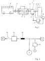
- the UPS system 1 shown in Figure 1has an electrical Machine 2 in the form of a synchronous machine, acting as a motor or is operable as a generator.
- a rotor 3 of the electric Machine 1is provided with an input / output shaft 4 one here Planetary gear formed differential gear 5 rotatably connected.
- Another input / output shaft 6 of the differential gear 5is rotatably connected to a flywheel 7.
- a third input / output shaft 8 of the differential gear 5is festgetrieblich with the rotor of an electric auxiliary machine 9 coupled.
- a control device 10the speed of the input / output shaft via a sensor 24 6 picks up here as an electric synchronous machine trained auxiliary machine 9 controlled so that the Speed of the input / output shaft 4 is kept constant, even if the speed of the flywheel 7 during operation of the electric Machine 2 drops as a generator.
- the control device 10also serves to flywheel 7 by appropriate control the electric auxiliary machine 9 on a opposite the rotor 3 of the electric machine 2 increased speed bring when the electric machine 2 operated as a motor is to as much kinetic energy in the flywheel. 7 to save, which is used to bridge power outages Electricity network, the UPS system 1 is connected in parallel, for available to stand.
- the one-line circuit diagram according to FIG. 2shows the supply a load 13 with power either through an external power source 14, which is typically a public power grid act, or by the electric machine 2.
- an external power source 14which is typically a public power grid act, or by the electric machine 2.
- a first Switch 15a thyristor 16 and a throttle 17 is arranged.
- the throttle 17may also be T-shaped in a known manner be connected, the throttle 17 in the desirable extent also on the coming of the electric machine 2 power acts.
- the electric machine 2is between the throttle 17 and the load 13 connected.
- An inverter 18is found but before the electric auxiliary machine 9 and the load.
- the final speed of the flywheel 7is then finally reached, by both the electric machine 2 and the electric Machine 9 can be operated as a motor. After reaching the End speed of the flywheel 7 are only friction losses and Like. Power losses with the two electrical machines. 2 and 9 to raise.
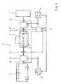
- the embodiment of the UPS system 1 according to FIG. 3differs from that according to FIG. 1 in two points.
- Firstis the controller 10 designed more complex and accesses another sensor 19, the speed of the input / output shaft 4 off.
- Another sensor 20is on the output shaft the internal combustion engine 11 is provided and supplies the control device 10 with the speed of the internal combustion engine.
- Thisuses the controller 10 to the other with another electric auxiliary machine 21, the gear ratio of a further, here also designed as a planetary gear Adjust differential gear 22.
- the further differential gear 22is between a switchable coupling 23 and the Internal combustion engine 11 is provided. On the other side of the switchable coupling 23, by the control device 10th is pressed, there is the rotor 3 of the electric machine 2.
- the differential gear 22can speed differences between the internal combustion engine 11 and the rotor 3 of the electric Machine 2 are balanced. Very large speed differences, as for example when the internal combustion engine 11 occur is by disengaging the clutch 23rd encountered.
- the clutch 23could for this purpose as a one-way clutch be formed. It is even conceivable on the Clutch 23 completely dispense. But then you have to stand still the internal combustion engine 11, the further electric auxiliary machine 21 reach a relatively high speed, and the differential gear 22 is constantly stressed and leads to friction losses.
- Using the planetary gear 22 and the Electric auxiliary machine 21may also be a separate starter motor for the internal combustion engine 11 omitted, this makes certain demands on the control device 10 to while a synchronization of the rotor 3 of the electric machine. 2 to ensure a constant speed.
- An overrunning clutch 12can not be used then.
- the embodiment of the UPS system 1 according to FIG 4deviates compared to that of Figure 3 in other points of the Embodiment of Figure 1 from.
- the Auxiliary machine 9is designed as an electrical asynchronous machine, in the network operation of the electric machine 2 as a motor easy attachment to the mains also as a motor is operated.
- the auxiliary machine 9 of the embodiment according to Figure 4simply turned off.
- the regulation of the third input / output shaft 8 of the differential gear 5is then carried out a separate mechanical brake 25, here one on the shaft the auxiliary machine 9 arranged brake disc 26 and this beauf needde Brake shoes 27 has.
- the braking force of the brake 25is controlled by the controller 10 so that the speed of the Input / output shaft 4 is kept constant until the Input / output shaft 8 is braked to zero. If so still afterwards, d. H. at further decreasing speed, kinetic energy can be recovered from the flywheel 7 should, the auxiliary machine 9 with respect to the network operation reverse polarity to the electric generator operated Machine 2 are attached to the input / output shaft. 8 this time to drive in the reverse direction.
- the exact Control of the speed of the auxiliary machine 9 for constant maintenanceThe speed of the electric machine 2 also takes place with it the mechanical brake 25.
- the mechanical brake 25In contrast to the embodiments according to Figures 1 and 3 is in the embodiment according to the Figure 4 aware kinetic energy with the mechanical Brake 25 destroyed, d. H. converted into heat.
- the embodiment of the UPS system 1 according to Figure 4is thus characterized in total by a particularly low effort for the controller 10 off. Farther does the embodiment of an electric machine. 2 usual and thus cost-effective design that means without continuous input / output shaft 4, off.
- the internal combustion engine 11is on the overrunning clutch 12 below Interposition of the gears 28 and 29 as an example of a simple mechanical branching gear to the input / output shaft 4 can be coupled.
Landscapes
- Business, Economics & Management (AREA)
- Emergency Management (AREA)
- Engineering & Computer Science (AREA)
- Power Engineering (AREA)
- Stand-By Power Supply Arrangements (AREA)
- Electric Propulsion And Braking For Vehicles (AREA)
- Supply And Distribution Of Alternating Current (AREA)
- Control Of Multiple Motors (AREA)
- Connection Of Motors, Electrical Generators, Mechanical Devices, And The Like (AREA)
- Steering Controls (AREA)
- Current-Collector Devices For Electrically Propelled Vehicles (AREA)
- Hybrid Electric Vehicles (AREA)
- Electrophotography Configuration And Component (AREA)
Abstract
Description
Translated fromGermanDie Erfindung bezieht sich auf eine Vorrichtung zur unterbrechungsfreienStromversorgung mit einer einen Rotor aufweisenden,als Motor oder als Generator betreibbaren elektrischen Maschine,die ohne Zwischenschaltung eines eine variable Eingangsfrequenz aufweisenden Umrichters mit einermit Wechselstrom zu versorgenden Last verbunden ist, mit einemSchwungrad, das über eine variable Übersetzung aufweisende Kopplungsmittelan den Motor angekoppelt ist, und mit Steuermittelnfür die Übersetzung der Kopplungsmittel, die die Drehzahl dermit der in dem Schwungrad gespeicherten kinetischen Energie alsGenerator betriebenen elektrischen Maschine zumindest über einenDrehzahlbereich des Schwungrads konstant halten,
wobei die Kopplungsmittel ein Differenzgetriebe mit drei Eingangs-/Ausgangswellenaufweisen und die Steuermittel eine als Motor betreibbare elektrische Hilfsmaschine undeine regelbare Bremse aufweisen, die an der dritten Eingangs-/Ausgangswelle des Differenzgetriebesangreifen.The invention relates to a device for uninterruptible power supply with a rotor having, operable as a motor or as a generator electric machine, which is connected without interposition of a variable input frequency having inverter with a to be supplied with AC load, with a flywheel over a variable ratio coupling means is coupled to the engine, and with control means for the translation of the coupling means which keep constant the speed of the stored with the kinetic energy stored in the flywheel as a generator electric machine at least over a speed range of the flywheel
wherein the coupling means comprises a differential gear with three input / output shafts and the control means comprise an electric auxiliary machine operable as a motor and a controllable brake, which engage the third input / output shaft of the differential gear.
vorrichtungen zur unterbrechungsfreien Stromversorgung, dieallgemein und auch hier meistens als USV-Anlagen bezeichnetwerden, dienen dazu, insbesondere kurzzeitige Ausfälle einesStromnetzes, welches normalerweise zur Versorgung einer Last mitWechselstrom verwendet wird, zu überbrücken. Dabei ist es einbekanntes Konzept, mit Hilfe des Stromnetzes zusätzlich zu derLast eine elektrische Maschine als Motor zu betreiben, die einSchwungrad auf eine bestimmte Drehzahl bringt und kontinuierlichauf dieser Drehzahl hält. Wenn das Netz ausfällt, kann die indem Schwungrad gespeicherte kinetische Energie genutzt werden,um die elektrische Maschine als Generator zu betreiben, um dieLast mit Wechselstrom zu versorgen. Dabei nimmt die kinetischeEnergie des Schwungrads und damit seine Drehzahl naturgemäß ab.Bei starrer Ankopplung des Schwungrads an den Generator bedeutetdies, daß ein Umrichter mit variabler Eingangsfrequenz zwischendem Generator und der Last vorgesehen sein muß, um die Last mitWechselstrom konstanter Frequenz zu versorgen. Ein solcherUmrichter ist ebenso wie ein Wechselrichter, der einer Gleichstrommaschineals elektrische Maschine nachgeschaltet werden müßte, im besonders interessierenden Mittelspannungsbereich derGrößenordnung 10.000 Volt eine komplizierte Einrichtung, wenn erfür größere Leistungen, d. h. für größere Ströme ausgelegtwerden soll. Aber auch bei Auslegung für große Leistungen ist ergegenüber Kurzschlußströmen extrem empfindlich.devices for uninterruptible power supply, thegenerally and also here mostly called UPS systemsserve, in particular short-term failures of aPower grid, which is normally used to supply a loadAC is used to bridge. It is oneknown concept, with the help of the power grid in addition to theLoad an electric machine to operate as a motorFlywheel brings to a certain speed and continuouslystops at this speed. If the power fails, the inthe flywheel stored kinetic energy are used,to operate the electric machine as a generator to theTo supply load with alternating current. It takes the kineticEnergy of the flywheel and thus its speed naturally.For rigid coupling of the flywheel to the generator meansThis is because a variable frequency input frequency converter is usedthe generator and the load must be provided to the load withSupply alternating current of constant frequency. Such aInverter is just like an inverter that is a DC machinebe connected downstream as an electrical machinewould, in the particular medium voltage range of interestMagnitude 10,000 volts a complicated device when hefor larger services, d. H. designed for larger currentsshall be. But he is also synonymous with interpretation for great achievementsextremely sensitive to short-circuit currents.
Es ist daher bekannt, eine Vorrichtung zur unterbrechungsfreienStromversorgung nach der eingangs beschriebenen Art auszubilden,bei der das Schwungrad nicht starr an den Rotor der elektrischenMaschine angekoppelt ist, sondern über eine variable Übersetzungaufweisende Kopplungsmittel. Bei einer konkreten bekanntenunterbrechungsfreien Stromversorgung der eingangs beschriebenenArt der Firma HOLEC/HITEC weisen die Kopplungsmittel eineelektromagnetische Kupplung zwischen der elektrischen Maschineund dem Schwungrad auf. Die elektromagnetische Kupplung erlaubtes, daß sich das Schwungrad abbremst, ohne daß sich die Drehzahlder als Generator betriebenen elektrischen Maschine verringert.Bei einfachem Aufbau der elektromagnetischen Kupplung ist diessolange möglich, wie die Drehzahl des Schwungrads größer ist alsdie gewünschte konstante Drehzahl des Generators. Dabei ist indiesem Fall erforderlich, daß das Schwungrad über einen anderenDrehmomentübertragungsweg von der als Motor betriebenenelektrischen Maschine auf eine größere Drehzahl gebracht wirdals die Drehzahl der elektrischen Maschine. Wenn die elektromagnetischeKupplung auch eine Aufwärtsübersetzung der jeweilsantreibenden Eingangsdrehzahl ermöglichen soll, ist der Aufbauder elektromagnetischen Kupplung und der Aufbau der hierfürnotwendigen Steuermittel besonders aufwendig.It is therefore known, a device for uninterruptibleForm power supply according to the type described above,when the flywheel is not rigidly connected to the rotor of the electricMachine is coupled, but via a variable translationhaving coupling agents. At a specific knownuninterruptible power supply of the initially describedType of company HOLEC / HITEC have the coupling agents oneelectromagnetic coupling between the electric machineand the flywheel. The electromagnetic clutch allowedit that the flywheel slows down without the speedreduces the operated as a generator electric machine.With a simple construction of the electromagnetic clutch, this isas long as possible, as the speed of the flywheel is greater thanthe desired constant speed of the generator. It is inThis case requires that the flywheel on anotherTorque transmission path of the engine operatedelectric machine is brought to a higher speedas the speed of the electric machine. When the electromagneticClutch also has an up-ratio of eachis to enable driving input speed, is the structurethe electromagnetic clutch and the structure of thisnecessary control means particularly expensive.
Aus dem Stand der Technik der USV-Anlagen ist es auch bekannt,für längere Ausfälle eines Netzes eine Brennkraftmaschine vorzusehen,um die elektrische Maschine als Generator anzutreiben,wenn ein längerer Stromausfall zu überbrücken ist. Der Rotor derelektrischen Maschine wird mit dem Generator über eine Freilaufkupplungoder eine schaltbare Kupplung verbunden. Wenn der elektrischenMaschine kein Umrichter mit variabler Eingangsfrequenznachgeschaltet ist, muß die Drehzahl der Brennkraftmaschine bereits die Drehzahl der elektrischen Maschine erreicht haben, bevor an die elektrischeMaschine angekoppelt werden darf; anschließend muß ihre Drehzahl konstant gehaltenwerden.It is also known from the prior art of the UPS systemsto provide an internal combustion engine for longer failures of a network,to power the electric machine as a generator,if a prolonged power failure is to be bridged. The rotor of theElectric machine is connected to the generator via a one-way clutchor a switchable coupling connected. When the electricMachine no inverter with variable input frequencyis downstream, the speed of the internal combustion enginealready reached the speed of the electric machine before going to the electricalMachine may be coupled; then their speed must be kept constantbecome.
Aus der US-4 278 928 ist eine elektrische Generatoranordnung bekannt, bei der derEingangswelle eines elektrischen Generators ein Differenzgetriebe in Form einesPlanetengetriebes vorgeschaltet ist. Dabei ist die Eingangswelle des Generators mit demSonnenrad des Planetengetriebes verbunden. Der Läufer der Planeten des Planetengetriebesist mit der Eingangswelle der gesamten elektrischen Generatoranordnung verbunden. DerZahnkranz des Planetengetriebes kann durch einen hydraulischen Antrieb mit verschiedenerDrehzahl angetrieben werden, um das Übersetzungsverhältnis des Planetengetriebes so zuvariieren, daß die Drehzahl des Generators auch bei schwankender Drehzahl an derEingangswelle der gesamten elektrischen Generatoranordnung konstant gehalten wird. DasHydraulikmedium für den hydraulischen Antrieb wird von Pumpen bereitgestellt, die von dersich auf konstanter Drehzahl befindlichen Eingangswelle des Generators oder einem anderenTeil des Generators angetrieben wird.From US-4,278,928 an electric generator arrangement is known in which theInput shaft of an electric generator, a differential gear in the form of aPlanetary gear is connected upstream. Here, the input shaft of the generator with theSun gear of the planetary gear connected. The runner of the planets of the planetary gearis connected to the input shaft of the entire electric generator assembly. Of theSprocket of the planetary gear can by a hydraulic drive with differentSpeed are driven to the gear ratio of the planetary gear so toovary that the speed of the generator even at fluctuating speed at theInput shaft of the entire electric generator assembly is kept constant. TheHydraulic fluid for the hydraulic drive is provided by pumps supplied by theAt constant speed located input shaft of the generator or anotherPart of the generator is driven.
Aus der US 4 525 661 ist eine Vorrichtung für eine unterbrechungsfreie Stromversorgung miteiner als Motor und Generator arbeitenden elektrischen Maschine bekannt. Diese Maschine ist drehfestmit einem Laufer eines Planetengetriebes verbunden, dessen Sonnenrad mit einer erstenelektrischen Hilfsmaschine in Verbindung steht und dessen Zahnkranz mit einer zweitenelektrischen Hilfsmaschine und einem Schwungrad in Antriebsverbindung steht. Das Sonnenrad istdarüber hinaus über eine Bremse mit einem Gehäuse und (bei gelöster Bremse)über eine Kupplung mit einer Brennkraftmaschine verbindbar. In einem erstenBetriebszustand (Stand-by-Betrieb) wird die Vorrichtung von der elektrischen Maschine angetrieben,wobei das Sonnenrad und die erste elektrische Hilfsmaschine über die Bremse blockiert sind, währenddas Schwungrad und die zweite etektrische Hilfsmaschine in unbelastetem zustand rotieren. Ineinem zweiten Betriebszustand (Einbruch der Energieversorgung) wird die elektrische Maschine alsGenerator betrieben, wobei unter Verwendung des Stromes, der durch die zweite elektrischeHilfsmaschine gewonnen worden ist, die erste elektrische Hilfsmaschine gestarted wird. DasSchwungrad, verlangsamt sich und überträgt Energie. Durch eine Beschleunigung der erstenelektrischen Hilfsmaschine kann der Generator auf einer konstanten Drehzahl gehalten werden.From US 4 525 661 a device for an uninterruptible power supply witha working as a motor and generator electric machine known. This machine is rotatableconnected to a Laufer a planetary gear, the sun gear with a firstelectric auxiliary machine is in communication and whose sprocket with a secondelectric auxiliary machine and a flywheel is in drive connection. The sun wheel ismoreover, a brake with a housing and (with the brake released)connectable via a clutch with an internal combustion engine. In a firstOperating state (stand-by mode), the device is driven by the electric machine,wherein the sun gear and the first auxiliary electric machine are blocked by the brake whilerotate the flywheel and the second auxiliary electric machine in unloaded condition. InIn a second operating state (power supply breakdown), the electric machine asGenerator operated using the current passing through the second electricalAuxiliary machine has been won, the first electric auxiliary machine is started. TheFlywheel slows down and transmits energy. By accelerating the firstelectric auxiliary machine, the generator can be kept at a constant speed.
Der Erfindung liegt die Aufgabe zugrunde, eine unterbrechungsfreie Stromversorgung dereingangs beschriebenen Art aufzuzeigen, die einen besonders einfachen Aufbau aufweist.The invention is based on the object, an uninterruptible power supply ofinitially described type show that has a particularly simple structure.
Erfindungsgemäß wird diese Aufgabe dadurch gelöst, daßdie Steuermittel so ausgebildet sind,daß beim Betreiben der elektrischen Maschine als Motor zum Erreichen einer gewünschtenEnddrehzahl des Schwungrads die Hilfsmaschine als ebenfalls Motor betrieben wird.According to the invention, this object is achieved in thatthe control means are designedthat when operating the electric machine as a motor to achieve a desiredEnd speed of the flywheel, the auxiliary machine is also operated as a motor.
Bei der neuen USV-Anlagewird beimBetreiben der elektrischen Maschine als Motor mit Hilfe der Hilfsmaschine zusätztiche Kinetische Energie in demSchwungrad gespeichert. Beim Betreiben der elektrischen Maschine als Generator kann mitHilfe der regelbaren Bremse die Drehzahl der elektrischen Maschine zumindest so langekonstant gehalten werden, bis die Drehzahl der dritten Eingangs-/Ausgangswelle des Planetengetriebesauf null abgesunken ist.At the new UPS systemis atOperating the electric machine as an engine with the help of the auxiliary machine additional tiche kinetic energy in theFlywheel saved. When operating the electric machine as a generator can withHelp the adjustable brake the speed of the electric machine at least as longbe held constant until the speed of the third input / output shaft of the planetary geardropped to zero.
Typischerweise ist die Leistungsfähigkeit der Hilfsmaschine bei der neuen USV-Anlage deutlichkleiner als die Leistungsfähigkeit der elektrischen Maschine.Typically, the performance of the auxiliary machine in the new UPS system is clearless than the efficiency of the electric machine.
Das Differenzgetriebe der neuen USV-Anlage kann beispielsweise ein mechanischesDifferential oder ein Planetengetriebe sein.The differential gear of the new UPS system, for example, a mechanicalBe differential or a planetary gear.
Im Vergleich zur US 4 525 661 ist die erfindungsgemäße Vorrichtung kompakt aufgebaut,wobei auch mit lediglich einer elektrischen Hilfsmaschine die volle Funktion gewährleistetwerden kann. Zusätzlich können infolge der Überlagerung der Drehbewegungen derHilfsmaschine und der elektrischen Maschine höhere Drehzahlen des Schwungrades erzieltwerden, wodurch eine größere Energie im Schwungrad gespeichert werden kann. Alternativoder zusätzlich kann durch das Zusammenspiel der elektrischen Maschine und derHilfsmaschine der Drehzahlbereich dieser Maschinen geeignet angepasst werden, wodurchbeispielsweise andere elektrische Aggregate einsetzbar werden oder die Betriebsbereiche derAggregate optimiert werden können.Compared to US Pat. No. 4,525,661, the device according to the invention has a compact construction.whereby even with only one electric auxiliary machine ensures full functioncan be. In addition, due to the superposition of the rotational movements of theAuxiliary machine and the electric machine achieved higher speeds of the flywheelwhich allows greater energy to be stored in the flywheel. alternativeor additionally, by the interaction of the electric machine and theAuxiliary machine, the speed range of these machines can be adjusted appropriately, therebyFor example, other electrical units can be used or the operating ranges ofAggregates can be optimized.
In einer bevorzugten Ausführungsform der neuen USV-Anlage istdas Differenzgetriebe als Planetengetriebe mit einem Sonnenrad,einem Planetenräder tragenden Läufer und einem Zahnkranz ausgebildet,wobei das Sonnenrad mit der zu dem Schwungrad und derLäufer mit der zu der elektrischen Maschine führenden Eingangs-/Ausgangswelledrehfest verbunden ist und wobei der Zahnkranzmit der zu der Hilfsmaschine führenden Eingangs-/Ausgangswellefestgetrieblich gekoppelt ist. Das Planetengetriebe ist beidieser Anschlußweise für eine Übersetzung der Drehzahl desMotors in eine höhere Übersetzung der Drehzahl des Schwungradsvorgesehen, um möglichst viel kinetische Energie in einemSchwungrad mit gegebenem Trägheitsmoment zu speichern. Mit derelektrischen Hilfsmaschine wird diese Übersetzung durchgegensinnigen Antrieb des Zahnkranzes noch gesteigert. Bei derAusnutzung der kinetischen Energie des Schwungrads wird die zur Steigerung der Übersetzung des Planetengetriebes mit derHilfsmaschine aufgebrachte elektrische Energie zurückgewonnen,soweit sie nicht zu einem geringen Teil mit der regelbarenBremse vernichtet, daß heißt in Wärme umgewandelt wird.In a preferred embodiment of the new UPS system isthe differential gear as a planetary gear with a sun gear,a planetary wheel bearing rotor and a ring gear formed,with the sun gear with the flywheel and theRunner with leading to the electric machine input / output shaftrotatably connected and wherein the sprocketwith the leading to the auxiliary machine input / output shaftfestgetrieblich is coupled. The planetary gear is atthis connection for a translation of the speed ofMotors in a higher ratio of the speed of the flywheelprovided as much kinetic energy in oneFlywheel with a given moment of inertia to save. With theelectric auxiliary machine is this translation byopposing drive of the ring gear still increased. In theExploitation of the kinetic energy of the flywheel becomes theIncreasing the ratio of the planetary gear with theAuxiliary machine recovered electrical energy recoveredas far as not to a small extent with the controllableBrake destroys, that is, is converted into heat.
Bei der regelbaren Bremse kann es sich um eine zusätzlichemechanische Bremse handeln. Es kann aber auch die elektrischeHilfsmaschine so ausgebildet sein, daß sie als elektromagnetischeBremse betreibbar ist. Der dabei in der Hilfsmaschineerzeugte Strom kann vernichtet oder seinerseits als Notstromgenutzt werden.The adjustable brake may be an additionalact mechanical brake. But it can also be the electricalAuxiliary machine be designed so that they are electromagneticBrake is operable. The case in the auxiliary machinegenerated electricity can be destroyed or in turn as emergency powerbe used.
Die elektrische Hilfsmaschine ist im einfachsten Fall eineAsynchronmaschine, die beim Betreiben als Motor von denSteuermitteln direkt an das Stromnetz angehängt wird. EineAsynchronmaschine als Hilfsmaschine ist mit einer zusätzlichenregelbaren Bremse zu kombinieren. Wenn mit dieser Bremse dieDrehzahl der dritten Eingangs-/Ausgangswelle des Differenzgetriebesbis auf null abgebremst worden ist, wobei dieAsynchronmaschine typischerweise ausgeschaltet gewesen ist,können die Steuermittel die Asynchronmaschine mit gegenüber demNetzbetrieb umgekehrter Polung an die als Generator betriebeneelektrische Maschine anhängen, um die dritte Eingangs-/Ausgangswelledes Differenzgetriebes nun in umgekehrter Drehrichtung zubeschleunigen. Die genaue Drehzahlregelung für die Konstanthaltungder Drehzahl der elektrischen Maschine erfolgt dabeiwiederum mit Hilfe der mechanischen Bremse.The electric auxiliary machine is in the simplest case oneAsynchronous machine operating as motor of the engineTaxes attached directly to the mains. AAsynchronous machine as auxiliary machine is with an additionalto combine adjustable brake. If with this brake theSpeed of the third input / output shaft of the differential gearhas been slowed down to zero, with theAsynchronous machine has typically been off,the control means may be compared with the asynchronous machineMains operation reverse polarity to the operated as a generatorattach electric machine to the third input / output shaftof the differential gear now in the reverse directionaccelerate. The precise speed control for constant maintenanceThe speed of the electric machine takes placeagain with the help of the mechanical brake.
Wenn die elektrische Hilfsmaschine eine Synchronmaschine ist,die über einen Umrichter mit der elektrischen Maschine und derLast verbindbar ist, kann die Hilfsmaschine als die Bremse oderzumindest zur Bereitstellung eines Teils der Bremsleistungbetrieben werden. Zudem kann der in der Hilfsmaschine beimBremsen erzeugte Strom der Last über den Umrichter zur verfügunggestellt werden, so daß die elektrische Energie nicht verlorengeht. Weiterhin eröffnet die Verwendung der Synchronmaschine mitdem Umrichter die Ausnutzung der kinetischen Energie des Schwungrads bis dessen Drehzahl theoretisch bis auf nullabgesunken ist, d.h. die kinetische Energie des Schwungrads kannvoll ausgenutzt werden. Im niedrigen Drehzahlbereich desSchwungrads ist zur Aufrechterhaltung der Drehzahl des Rotorsder elektrischen Maschine wieder ein Betrieb der elektrischenHilfsmaschine als Motor in in Bezug auf den Netzbetrieb entgegengesetzterumlaufrichtung erforderlich. Die hierfür benötigteEnergie stellt die elektrische Maschine bereit, die ihrerseitsvon der elektrischen Hilfsmaschine als Motor angetrieben wird,so daß bis auf die verlustleistungen die Energiebilanz durch dieelektrische Hilfsmaschine ausgeglichen ist. Über den Umrichterzwischen der elektrischen Hilfsmaschine und der elektrischenMaschine bzw. der Last fließt nur ein Teil des Gesamtstroms. DerUmrichter ist daher von deutlich einfacherem Aufbau als für dieelektrische Maschine, wenn diese mit variabler Drehzahl betriebenwürde.If the auxiliary electric machine is a synchronous machine,via an inverter with the electric machine and theLoad is connectable, the auxiliary machine can be used as the brake orat least to provide a part of the braking poweroperate. In addition, in the auxiliary machine atBraking provided power to the load through the inverterbe placed so that the electrical energy is not lostgoes. Furthermore, the use of the synchronous machine opens withthe inverter exploits the kinetic energy of the inverterFlywheel to its speed theoretically to zerohas dropped, i. the kinetic energy of the flywheel canbe fully exploited. In the low speed range ofFlywheel is used to maintain the speed of the rotorthe electric machine is again an operation of the electricAuxiliary machine as a motor in relation to the network operation oppositedirection of rotation required. The required for thisEnergy provides the electrical machine, which in turnpowered by the electric auxiliary machine as a motor,so that except for the loss of energy balance by theelectric auxiliary machine is balanced. About the inverterbetween the electric auxiliary machine and the electricMachine or the load flows only a part of the total current. Of theInverter is therefore of a much simpler structure than for theelectric machine when operated at variable speedwould.
Die elektrische Hilfsmaschine kann auch eine Gleichstrommaschinesein, die über einen Wechselrichter mit der elektrischen Maschineund der Last verbindbar ist. Dabei sind dieselben Betriebsartenmöglich wie bei einer Asynchronmaschine mit Umrichter.The auxiliary electric machine can also be a DC machinebe using an inverter with the electric machineand the load is connectable. These are the same modesas possible with an asynchronous machine with inverter.
Die elektrische Maschine der neuen USV-Anlage ist in aller Regeleine Synchronmaschine, die trotz großer Leistungsfähigkeit eineneinfachen Aufbau aufweist und zu günstigen Kosten verfügbar ist.The electrical machine of the new UPS system is usuallya synchronous machine, which despite great efficiency onehas simple structure and is available at low cost.
Ergänzend zu dem Schwungrad, das mit seiner kinetischen Energiezur Überbrückung kurzzeitiger Stromausfälle vorgesehen ist, kannder Rotor durch eine Brennkraftmaschine antreibbar sein, umlängerfristige Stromausfälle zu überbrücken. Dabei kann zwischendem Rotor und der Brennkraftmaschine eine von den Steuermittelnschaltbare Kupplung vorgesehen sein.In addition to the flywheel, with its kinetic energyis intended to bridge short-term power outages canthe rotor can be driven by an internal combustion engine toto bridge longer-term power outages. It can be betweenthe rotor and the internal combustion engine one of the control meansbe provided switchable coupling.
Besonders bevorzugt ist es, wenn zusätzlich aber auch alternativzu der schaltbaren Kupplung zwischen dem Rotor und der Brennkraftmaschineein Differenzgetriebe vorgesehen ist, dessendritte Eingangs-/Ausgangswelle an eine weitere elektrische Hilfsmaschine der Steuermittel angekoppelt ist. Die weitereHilfsmaschine dient zum Ausgleich von Drehzahlunterschiedenzwischen dem Rotor und der Brennkraftmaschine, insbesondere wenndie Brennkraftmaschine ihre mit der Drehzahl des Rotors übereinstimmendeoder zu dieser in einem festen Verhältnis stehendeEnddrehzahl noch nicht erreicht hat.It is particularly preferred if, in addition but also alternativelyto the switchable coupling between the rotor and the internal combustion enginea differential gear is provided, whosethird input / output shaft to another electricalAuxiliary machine of the control means is coupled. The othersAuxiliary machine is used to compensate for speed differencesbetween the rotor and the internal combustion engine, in particular whenthe internal combustion engine coincides with the speed of the rotoror to this in a fixed relationshipFinal speed has not yet reached.
In einer weiterentwickelten Ausführungsform kann bei der Brennkraftmaschineaufgrund des zwischen der Brennkraftmaschine unddem Rotor vorgesehenen Differenzgetriebes auf einen Anlassermotorverzichtet werden. Die zum Anlassen der Brennkraftmaschinenotwendige Energie wird dann von der elektrischen Maschinezusammen mit der weiteren Hilfsmaschine und damit letztlich vondem Schwungrad bereitgestellt.In a further developed embodiment, in the internal combustion enginedue to the between the engine andthe differential gear provided on the rotor to a starter motorbe waived. The for starting the internal combustion enginenecessary energy is then taken from the electric machinetogether with the other auxiliary machine and thus ultimately ofprovided to the flywheel.
Es ist aber auch möglich, zwischen dem Rotor und der Brennkraftmaschineeine Freilaufkupplung vorzusehen. In diesem Fall istein separater Anlassermotor für die Brennkraftmaschine erforderlich.But it is also possible between the rotor and the internal combustion engineto provide an overrunning clutch. In this case isa separate starter motor for the internal combustion engine required.
Das Hochfahren der elektrischen Maschine in einen Drehzahlbereich,in dem sie als Synchronmotor betreibbar ist, kann beider neuen USV-Anlage ohne zusätzlichen Motor mit Hilfe derelektrischen Hilfsmaschine erfolgen, wobei das Schwungradfestgehalten werden kann.Starting the electric machine in a speed range,in which it is operable as a synchronous motor can atthe new UPS system with no additional motor with the help ofelectrical auxiliary machine done, the flywheelcan be held.
Die Erfindung wird im folgenden anhand von Ausführungsbeispielennäher erläutert und beschrieben. Dabei zeigt:
Figur 1- die prinzipielle Anordnung der Bauteile der neuenVorrichtung zur unterbrechungsfreien Stromversorgungin einer ersten Ausführungsform,
Figur 2- einen Einlinien-Stromlaufplan zu der neuen Vorrichtungzur unterbrechungsfreien Stromversorgung in der Ausführungsformgemäß Figur 1,
Figur 3- die prinzipielle Anordnung der Bauteile einer zweitenAusführungsform der neuen Vorrichtung zur unterbrechungsfreienStromversorgung und
Figur 4- die prinzipielle Anordnung der Bauteile einer drittenAusführungsform der neuen Vorrichtung zur unterbrechungsfreienStromversorgung.
- FIG. 1
- the basic arrangement of the components of the new device for uninterruptible power supply in a first embodiment,
- FIG. 2
- 1 shows a single-circuit circuit diagram of the new device for uninterruptible power supply in the embodiment according to FIG. 1,
- FIG. 3
- the basic arrangement of the components of a second embodiment of the new device for uninterruptible power supply and
- FIG. 4
- the basic arrangement of the components of a third embodiment of the new device for uninterruptible power supply.
Die in Figur 1 dargestellte USV-Anlage 1 weist eine elektrischeMaschine 2 in Form einer Synchronmaschine auf, die als Motoroder als Generator betreibbar ist. Ein Rotor 3 der elektrischenMaschine 1 ist mit einer Eingang-/Ausgangswelle 4 eines hier alsPlanetengetriebe ausgebildeten Differenzgetriebes 5 drehfestverbunden. Eine weitere Eingang-/Ausgangswelle 6 des Differenzgetriebes5 ist mit einem Schwungrad 7 drehfest verbunden. Einedritte Eingangs-/Ausgangswelle 8 des Differenzgetriebes 5 istfestgetrieblich mit dem Rotor einer elektrischen Hilfsmaschine9 gekoppelt. Dabei ist die Eingangs-/Ausgangswelle 6 mit demSonnenrad, die Eingangs-/Ausgangswelle 4 mit dem Läufer derPlanetenräder und die Eingangs-/Ausgangswelle 8 mit dem Zahnkranzdes das Differenzgetriebe 5 bildenden Planetengetriebesverbunden. Bei dieser Anordnung ist durch eine Steuereinrichtung10, die über einen Sensor 24 die Drehzahl der Eingangs-/Ausgangswelle6 abgreift, die hier als elektrische Synchronmaschineausgebildete Hilfsmaschine 9 so ansteuerbar, daß dieDrehzahl der Eingangs-/Ausgangswelle 4 konstant gehalten wird,auch wenn die Drehzahl des Schwungrads 7 beim Betrieb der elektrischenMaschine 2 als Generator abfällt. Die Steuereinrichtung10 dient auch dazu, daß Schwungrad 7 durch entsprechende Ansteuerungder elektrischen Hilfsmaschine 9 auf eine gegenüberdem Rotor 3 der elektrischen Maschine 2 erhöhte Drehzahl zubringen, wenn die elektrische Maschine 2 als Motor betriebenwird, um möglichst viel kinetische Energie in dem Schwungrad 7zu speichern, die zum Überbrücken von Stromausfällen einesStromnetzes, dem die USV-Anlage 1 parallel geschaltet ist, zurverfügung zu steht. Für längere Unterbrechungen der externenStromversorgung ist eine Brennkraftmaschine 11 über eine Freilaufkupplung 12 an den Rotor 3 der elektrischen Maschine 2ankoppelbar, wobei die Freilaufkupplung 12 eine höhere aberkeine niedrigere Drehzahl des Rotors 3 gegenüber der Brennkraftmaschine1 erlaubt.The
Der Einlinien-Stromlaufplan gemäß Figur 2 zeigt die Versorgungeiner Last 13 mit Strom entweder durch eine externe Stromquelle14, bei der es sich typischerweise um ein öffentliches Stromnetzhandelt, oder durch die elektrische Maschine 2. Dabei sindzwischen der externen Stromquelle 14 und der Last 13 ein ersterSchalter 15 ein Thyristorschalter 16 und eine Drossel 17 angeordnet.Die Drossel 17 kann auch in bekannter Weise T-förmigverschaltet sein, wobei die Drossel 17 im wünschenswerten Umfangauch auf den von der elektrischen Maschine 2 kommenden Stromeinwirkt. Die elektrische Maschine 2 ist zwischen der Drossel 17und der Last 13 angeschlossen. Dabei ist kein Umrichter oderWechselrichter zwischengeschaltet. Ein Umrichter 18 findet sichjedoch vor der elektrischen Hilfsmaschine 9 und der Last.The one-line circuit diagram according to FIG. 2 shows the supplya
Im folgenden werden verschiedene Betriebszustände der USV-Anlage1 gemäß den Figuren 1 und 2 geschildert, wobei von einem Planetengetriebei13=-2 ausgegangen ist und die nachstehende Tabelleeine Übersicht über die Betriebszustände gibt:
Beim Normalbetrieb der Last 13 über die externe Stromquelle 14sind in dem Einlinien-Stromlaufplan gemäß Figur 2 der Schalter15 und der Thyristorschalter 16 geschlossen. Die Last 13 hängtan der Drossel 17 ebenso wie die als Motor betriebene elektrischeMaschine 2. Die Leistung, die von der Last 13 verbrauchtwird, wird vollständig der externen Stromquelle 14 entnommen,ebenso die verlustleistung der elektrischen Maschine 2 und derHilfsmaschine 9, mit der eine konstante Drehzahl in den Zahnkranzdes Planetengetriebes eingeleitet wird, um ein konstantesÜbersetzungsverhältnis zwischen den Eingangs-/Ausgangswellen 4und 6 des Planetengetriebes bereitzustellen.During normal operation of the
Beim Ausfall der externen Stromquelle 14 wird die im Normalbetriebgemäß 1. in dem Schwungrad 7 gespeicherte Energiezurückgewonnen. Dabei sind der Schalter 15 und der Thyristorschalter16 geöffnet. In dem in der obigen Tabelle wiedergegebenenBeispiel wird angenommen, daß die Last 13 einenLeistungsbedarf von 1.000 kW hat. Diese Leistung wird zunächstzum Teil von der elektrischen Maschine 2 als auch von derelektrischen Hilfsmaschine 9 bereitgestellt, die aufgrund derLeistungs- und Momentenverzweigung im Planetengetriebe von demSchwungrad 7 in ihrer Betriebsweise als Generator angetriebenwird. Dabei nimmt mit der Drehzahl des Schwungrads die Drehzahlder elektrischen Hilfsmaschine 9 kontinuierlich ab.In case of failure of the
Da mit der elektrischen Hilfsmaschine 9 die Drehzahl der alsGenerator betriebenen elektrischen Maschine 2 konstant gehaltenwird, kommt es zu einer Umkehrung ihrer Drehrichtung und desLeistungsflusses an der Hilfsmaschine 9, wenn die Drehzahl derelektrischen Hilfsmaschine 9 auf null abgesunken ist.Since with the electric
So muß die Hilfsmaschine 9 bei weiter abfallender Drehzahl desSchwungrads 7 als Motor betrieben werden. Die hierzu notwendige Energie wird von der als Generator betriebenen elektrischenMaschine 2 abgegriffen. Die elektrische Maschine 2 muß dahersowohl die Leistung der Last als auch die Leistung der elektrischenHilfsmaschine 9 erzeugen. Dies bedeutet aber keinezusätzliche Leistungsentnahme aus dem Schwungrad 7, weil dieLeistung der elektrischen Hilfsmaschine 9 der elektrischenMaschine 2 eingangsseitig wieder zur Verfügung gestellt wird.So must the
Beim Wiederaufladen des Schwungrads 7 mit der als Motor betriebenenelektrischen Maschine 2 wird die Drehrichtung der elektrischenHilfsmaschine 9 entgegen ihrer vorherigen Drehrichtungbeim Betrieb der elektrischen Maschine 2 als Generator kontinuierlichumgekehrt. Dabei wird beim Verzögern der Hilfsmaschinezunächst elektrische Energie erzeugt, die über den Umrichter 18der Last 13 bzw. der als Motor betriebenen elektrischen Maschinezur Verfügung gestellt wird.When recharging the
Nachdem die Drehzahl der elektrischen Hilfsmaschine wieder nullist, kommt es zur Leistungs- und Drehrichtungsumkehr der elektrischenHilfsmaschine.After the speed of the electric auxiliary machine returns to zerois, it comes to reversing the power and direction of the electricalAuxiliary machine.
Die Enddrehzahl des Schwungrads 7 wird dann letztlich erreicht,indem sowohl die elektrische Maschine 2 als auch die elektrischeMaschine 9 als Motor betrieben werden. Nach dem Erreichen derEnddrehzahl des Schwungrads 7 sind nur noch Reibungsverluste unddgl. Verlustleistungen mit den beiden elektrischen Maschinen 2und 9 aufzubringen.The final speed of the
Die Ausführungsform der USV-Anlage 1 gemäß Figur 3 unterscheidetsich von derjenigen gemäß Figur 1 in zwei Punkten. Zunächst istdie Steuereinrichtung 10 aufwendiger gestaltet und greift übereinen weiteren Sensor 19 auch die Drehzahl der Eingangs-/Ausgangswelle4 ab. Ein weiterer Sensor 20 ist an der Ausgangswelleder Brennkraftmaschine 11 vorgesehen und versorgt die Steuereinrichtung 10 mit der Drehzahl der Brennkraftmaschine. Dies nutztdie Steuereinrichtung 10 um zum anderen mit einer weiterenelektrischen Hilfsmaschine 21 das Übersetzungsverhältnis einesweiteren, hier ebenfalls als Planetengetriebe ausgebildetenDifferenzgetriebes 22 einzustellen. Das weitere Differenzgetriebe22 ist zwischen einer schaltbaren Kupplung 23 und derBrennkraftmaschine 11 vorgesehen. Auf der anderen Seite derschaltbaren Kupplung 23, die von der Steuereinrichtung 10betätigt wird, findet sich der Rotor 3 der elektrischen Maschine2. Mit dem Differenzgetriebe 22 können Drehzahlunterschiedezwischen der Brennkraftmaschine 11 und dem Rotor 3 der elektrischenMaschine 2 ausgeglichen werden. Sehr großen Drehzahlunterschieden,wie sie beispielsweise beim Stillstand der Brennkraftmaschine11 auftreten, wird durch auskuppeln der Kupplung 23begegnet. Die Kupplung 23 könnte zu diesem Zweck auch als Freilaufkupplungausgebildet werden. Es ist selbst denkbar, auf dieKupplung 23 ganz zu verzichten. Dann muß aber beim Stillstandder Brennkraftmaschine 11 die weitere elektrische Hilfsmaschine21 eine relativ hohe Drehzahl erreichen, und das Differenzgetriebe22 wird ständig beansprucht und führt zur Reibungsverlusten.Unter verwendung des Planetengetriebes 22 und derelektrischen Hilfsmaschine 21 kann auch ein separater Anlassermotorfür die Brennkraftmaschine 11 entfallen, wobei diesgewisse Anforderungen an die Steuereinrichtung 10 stellt, umdabei einen Gleichlauf des Rotors 3 der elektrischen Maschine 2mit konstanter Drehzahl zu gewährleisten. Eine Freilaufkupplung12 kann dann nicht verwendet werden.The embodiment of the
Die Ausführungsform der USV-Anlage 1 gemäß Figur 4 weichtgegenüber derjenigen gemäß Figur 3 in anderen Punkten von derAusführungsform gemäß Figur 1 ab. Gemäß Figur 4 ist dieHilfsmaschine 9 als elektrische Asynchronmaschine ausgebildet,die beim Netzbetrieb der elektrischen Maschine 2 als Motor durcheinfaches Anhängen an das Stromnetz ebenfalls als Motorbetrieben wird. Beim Betrieb der elektrischen Maschine 2 alsGenerator wird die Hilfsmaschine 9 der Ausführungsform gemäßFigur 4 einfach abgeschaltet. Die Regelung der dritten Eingangs-/Ausgangswelle 8 des Differenzgetriebes 5 erfolgt dann durcheine separate mechanische Bremse 25, die hier eine auf der Welleder Hilfsmaschine 9 angeordnete Bremsscheibe 26 und diese beaufschlagendeBremsbacken 27 aufweist. Die Bremskraft der Bremse 25wird von der Steuerung 10 so geregelt, daß die Drehzahl derEingangs-/Ausgangswelle 4 konstant gehalten wird, bis dieEingangs-/Ausgangswelle 8 auf null abgebremst ist. Wenn auchnoch anschließend, d. h. bei weiter abfallender Drehzahl,kinetische Energie aus dem Schwungrad 7 zurückgewonnen werdensoll, kann die Hilfsmaschine 9 mit gegenüber dem Netzbetriebumgekehrter Polung an die als Generator betriebene elektrischeMaschine 2 angehängt werden, um die Eingangs-/Ausgangswelle 8diesmal in umgekehrter Drehrichtung anzutreiben. Die genaueRegelung der Drehzahl der Hilfsmaschine 9 zur Konstanthaltungder Drehzahl der elektrischen Maschine 2 erfolgt auch dabei mitder mechanischen Bremse 25. Im Gegensatz zu den Ausführungsformengemäß den Figuren 1 und 3 wird bei der Ausführungsformgemäß der Figur 4 bewußt kinetische Energie mit der mechanischenBremse 25 vernichtet, d. h. in Wärme umgewandelt. Dafür ist aberauch keine Leistungselektronik für die Rückspeisung von mit derHilfsmaschine 9 erzeugtem Strom erforderlich. Darüberhinausentfällt durch die Verwendung einer Asynchronmaschine für dieHilfsmaschine 9 die Notwendigkeit eines Umrichters für derenBetrieb als Motor. Die Ausführungsform der USV-Anlage 1 gemäßFigur 4 zeichnet sich damit insgesamt durch einen besondersgeringen Aufwand für die Steuereinrichtung 10 aus. Weiterhingeht die Ausführungsform von einer elektrischen Maschine 2üblicher und damit kostengünstiger Bauart, daß heißt ohnedurchgehende Eingangs-/Ausgangswelle 4, aus. Die Brennkraftmaschine11 ist dabei über die Freilaufkupplung 12 unterZwischenschaltung der Zahnräder 28 und 29 als Beispiel für eineinfaches mechanisches Verzweigungsgetriebe an die Eingangs-/Ausgangswelle4 ankoppelbar. Durch das Zahnverhältnis derZahnräder 28 und 29 bzw. das Übersetzungsverhältnis des verzweigungsgetriebeskönnen unterschiedliche Nenndrehzahlen derBrennkraftmaschine 11 und der elektrischen Maschine 2 berücksichtigtwerden. In Figur 4 ist überdies eine weitere alternative Anordnungsmöglichkeit für die Brennkraftmaschine 11 beiVerwendung einer elektrischen Maschine 2 in Standardausführungin gestrichelter Linienführung dargestellt. Beim Ankoppeln derBrennkraftmaschine 11 an die Eingangs-/Ausgangswelle 6 ergibtsich jedoch der Nachteil, daß die Brennkraftmaschine nur überdas träge Schwungrad 7 auf die elektrische Maschine 2 einwirkt,wenn sie diese als Generator antreiben soll, wodurch das Hochfahrender Brennkraftmaschine 11 in den Drehzahlbereich ihrerNennleistung verzögert wird.The embodiment of the
- 1 -1 -
- USV-AnlageUPS
- 2 -2 -
- elektrische Maschineelectric machine
- 3 -3 -
- Rotorrotor
- 4 -4 -
- Eingangs-/AusgangswelleInput / output shaft
- 5 -5 -
- Differenzgetriebedifferential gear
- 6 -6 -
- Eingangs-/AusgangswelleInput / output shaft
- 7 -7 -
- Schwungradflywheel
- 8 -8th -
- Eingangs-/AusgangswelleInput / output shaft
- 9 -9 -
- elektrische Hilfsmaschineelectric auxiliary machine
- 10 -10 -
- Steuereinrichtungcontrol device
- 11 -11 -
- BrennkraftmaschineInternal combustion engine
- 12 -12 -
- FreilaufkupplungOverrunning clutch
- 13 -13 -
- Lastload
- 14 -14 -
- externe Stromquelleexternal power source
- 15 -15 -
- Schalterswitch
- 16 -16 -
- Thyristorschalterthyristor
- 17 -17 -
- Drosselthrottle
- 18 -18 -
- Umrichterinverter
- 19 -19 -
- Sensorsensor
- 20 -20 -
- Sensorsensor
- 21 -21 -
- elektrische Hilfsmaschineelectric auxiliary machine
- 22 -22 -
- Differenzgetriebedifferential gear
- 23 -23 -
- schaltbare Kupplungswitchable coupling
- 24 -24 -
- Sensorsensor
- 25 -25 -
- mechanische Bremsemechanical brake
- 26 -26 -
- Bremsscheibebrake disc
- 27 -27 -
- Bremsbackebrake shoe
- 28 -28 -
- Zahnradgear
- 29 -29 -
- Zahnradgear
Claims (10)
- A device for uninterruptedly supplying power, comprising an electricalmachine including a rotor and being operable as a motor or as a generator, theelectrical machine being connected to a load to be supplied with alternating currentwithout a d.c.-a.c. converter being arranged in between, a flywheel being coupled tothe rotor by coupling means having a variable ratio of transmission, and controlmeans for the transmission of the coupling means, the control means at least in acertain range of the number of rotations of the flywheel keeping constant the numberof rotations of the electrical machine being operated as a generator by the kineticenergy being stored in the flywheel, the coupling means including a differentialtransmission (5) having three input/output shafts (4, 6 and 8), and the control meansincluding an electrical auxiliary machine (9) being operable as a motor and acontrollable brake, the electrical auxiliary machine (9) and the controllable brakeengaging the third input/output shaft (8) of the differential transmission (5),characterized in that the control means are designed in such a way that theauxiliary machine (9) is also operated as a motor to reach the desired final number ofrotations of the flywheel (7), when the electrical machine (2) is operated as a motor.
- The device of claim 1,characterized in that the differential transmission (5) isa planetary transmission including a sun wheel, a cage rotor carrying planetarywheels and a gear rim, the sun wheel being fixedly connected to the input/outputshaft (6) leading to the flywheel (7) and the cage rotor being fixedly connected to the input/output shaft (4) leading to the electrical machine (2), and the gear rim beingcoupled to the input/output shaft (8) leading to the auxiliary machine (9) at a fixedratio of transmission.
- The device of claim 1 or 2,characterized in that the electrical auxiliarymachine (9) is also operable as the brake.
- The device of one of claims 1 to 3,characterized in that the electricalauxiliary machine (9) is an asynchronous machine.
- The device of one of claims 1 to 3,characterized in that the electricalauxiliary machine (9) is a synchronous machine being connectable to the electricalmachine (2) and to the load (13) via a converter (18).
- The device of one of claims 1 to 5,characterized in that the rotor (3) isdrivable by a combustion engine (11).
- The device of claim 6,characterized in that a clutch (23) is provided betweenthe rotor (3) and the combustion engine (11), the clutch (23) being switchable by thecontrol means.
- The device of claim 6,characterized in that an overrunning clutch (23) isprovided between the rotor (3) and the combustion engine (11).
- The device of claim 6, 7 or 8,characterized in that another differentialtransmission (22) is provided between the rotor (3) and the combustion engine (11),the third input/output shaft of the differential transmission (22) being coupled toanother electrical auxiliary machine (21) of the control means.
- The device of claim 9 as far as not dependent of 8,characterized in that thecombustion engine (11) does not include a separate starter motor.
Applications Claiming Priority (1)
| Application Number | Priority Date | Filing Date | Title |
|---|---|---|---|
| PCT/EP1999/007577WO2001028065A1 (en) | 1999-10-08 | 1999-10-08 | Device for providing an uninterrupted supply of power comprising an electrical machine and a flywheel |
Publications (2)
| Publication Number | Publication Date |
|---|---|
| EP1221190A1 EP1221190A1 (en) | 2002-07-10 |
| EP1221190B1true EP1221190B1 (en) | 2005-03-02 |
Family
ID=8167462
Family Applications (1)
| Application Number | Title | Priority Date | Filing Date |
|---|---|---|---|
| EP99952545AExpired - LifetimeEP1221190B1 (en) | 1999-10-08 | 1999-10-08 | Device for providing an uninterrupted supply of power comprising an electrical machine and a flywheel |
Country Status (8)
| Country | Link |
|---|---|
| US (1) | US6573626B1 (en) |
| EP (1) | EP1221190B1 (en) |
| AT (1) | ATE290261T1 (en) |
| AU (1) | AU6470099A (en) |
| DE (1) | DE59911711D1 (en) |
| ES (1) | ES2237170T3 (en) |
| PT (1) | PT1221190E (en) |
| WO (1) | WO2001028065A1 (en) |
Families Citing this family (34)
| Publication number | Priority date | Publication date | Assignee | Title |
|---|---|---|---|---|
| FR2805410B1 (en)* | 2000-02-23 | 2002-09-06 | Andre Rene Georges Gennesseaux | SELF-CONTAINED ELECTRICITY AND HEAT COGENERATION SYSTEM INCLUDING ENERGY STORAGE BY FLYWHEEL |
| US6507128B2 (en)* | 2001-05-23 | 2003-01-14 | General Electric Company | Low-energy storage fast-start uninterruptible power supply system and method |
| US6962223B2 (en)* | 2003-06-26 | 2005-11-08 | George Edmond Berbari | Flywheel-driven vehicle |
| CN1696503A (en)* | 2004-05-10 | 2005-11-16 | 刘本荣 | Generating set by using inertia energy sources |
| US7492057B2 (en)* | 2004-11-10 | 2009-02-17 | Baldwin Mark H | High reliability DC power distribution system |
| US7845298B2 (en)* | 2005-05-04 | 2010-12-07 | Honeywell International Inc. | Submersible vehicle object ejection system using a flywheel driven boost pump |
| US7624830B1 (en)* | 2005-07-22 | 2009-12-01 | Kevin Williams | Energy recoverable wheel motor |
| US7654355B1 (en)* | 2006-01-17 | 2010-02-02 | Williams Kevin R | Flywheel system for use with electric wheels in a hybrid vehicle |
| US7710081B2 (en) | 2006-10-27 | 2010-05-04 | Direct Drive Systems, Inc. | Electromechanical energy conversion systems |
| US9823715B1 (en)* | 2007-06-14 | 2017-11-21 | Switch, Ltd. | Data center air handling unit including uninterruptable cooling fan with weighted rotor and method of using the same |
| WO2009010819A1 (en)* | 2007-07-17 | 2009-01-22 | Renault Trucks | Powertrain comprising an optimized energy recovery system |
| GB2453733B (en)* | 2007-10-15 | 2012-12-05 | Cummins Generator Technologies | Power generation system |
| US8310123B2 (en) | 2008-07-28 | 2012-11-13 | Direct Drive Systems, Inc. | Wrapped rotor sleeve for an electric machine |
| US20100283266A1 (en)* | 2009-05-06 | 2010-11-11 | Averox North America Inc. | Magnetic field powered electrical generating system |
| US20100304920A1 (en)* | 2009-05-28 | 2010-12-02 | Bernard Joseph Simon | Hybrid Assembly , A Hybrid Power-Train , And A Method For Operating A SelectivelyMovable Assembly |
| JP4947124B2 (en)* | 2009-11-05 | 2012-06-06 | 株式会社デンソー | In-vehicle power transmission system |
| US8544575B1 (en)* | 2009-12-02 | 2013-10-01 | Mainstream Engineering Corporation | Lightweight internal combustion/electric hybrid power source for vehicles |
| US8212442B1 (en)* | 2010-01-07 | 2012-07-03 | Wayne Paul Bishop | Torque / energy transfer method and apparatus |
| CN103338955B (en)* | 2010-11-30 | 2016-08-10 | Dti集团有限公司 | Drive mechanism for vehicle |
| US8627914B2 (en) | 2011-11-10 | 2014-01-14 | Arc Energy Recovery, Inc. | Energy recovery drive system and vehicle with energy recovery drive system |
| US9531289B2 (en)* | 2012-04-27 | 2016-12-27 | Raytheon Company | Electro-mechanical kinetic energy storage device and method of operation |
| US9369077B1 (en)* | 2013-03-15 | 2016-06-14 | Daniel M. Gates | Differential speed control apparatus |
| US10027216B2 (en) | 2013-04-26 | 2018-07-17 | No Fossil Energy, Llc | Hybrid machine for sustainable energy |
| US9531247B2 (en) | 2014-04-04 | 2016-12-27 | Raytheon Company | Inertial energy storage system and hydro-fluoro-ether power transformer scheme for radar power systems and large PFN charging |
| US9911532B2 (en) | 2014-08-25 | 2018-03-06 | Raytheon Company | Forced convection liquid cooling of fluid-filled high density pulsed power capacitor with native fluid |
| US9464634B2 (en)* | 2014-09-24 | 2016-10-11 | International Business Machines Corporation | Air-moving assemblies with flywheels |
| US9837996B2 (en) | 2015-01-07 | 2017-12-05 | Raytheon Company | Method and apparatus for control of pulsed power in hybrid energy storage module |
| US9667232B2 (en) | 2015-05-13 | 2017-05-30 | Raytheon Company | System and method for parallel configuration of hybrid energy storage module |
| US9504188B1 (en) | 2015-11-30 | 2016-11-22 | International Business Machines Corporation | Air-moving assembly with auxiliary turbine drive |
| US11038398B2 (en) | 2018-06-26 | 2021-06-15 | Raytheon Company | System and method for damping of torsional oscillations in large inertial energy storage systems |
| BE1026573B1 (en)* | 2018-08-28 | 2020-03-30 | Euro Diesel S A | Method of supplying an electrical appliance with direct current and accumulator of electrical energy |
| US11418031B2 (en) | 2020-05-08 | 2022-08-16 | Raytheon Company | Actively-controlled power transformer and method for controlling |
| US20220173648A1 (en)* | 2020-11-30 | 2022-06-02 | Ronald Vang | Mech-elect generator |
| CN113489230B (en)* | 2021-07-13 | 2022-11-18 | 坎德拉(深圳)新能源科技有限公司 | A new frequency modulation system based on flywheel energy storage technology |
Citations (1)
| Publication number | Priority date | Publication date | Assignee | Title |
|---|---|---|---|---|
| US4525661A (en)* | 1980-09-02 | 1985-06-25 | Endre Mucsy | Stand-by electrical supply source |
Family Cites Families (16)
| Publication number | Priority date | Publication date | Assignee | Title |
|---|---|---|---|---|
| US2376421A (en)* | 1943-06-07 | 1945-05-22 | Woodward Governor Co | Method and apparatus for producing alternating current of precisely controlled frequency |
| US3221172A (en)* | 1962-08-29 | 1965-11-30 | John G Stevens | No-break power supply |
| FR1576528A (en)* | 1968-05-17 | 1969-08-01 | ||
| DE2739980A1 (en) | 1976-09-08 | 1978-03-09 | Lucas Industries Ltd | GENERATOR ARRANGEMENT |
| US4233858A (en) | 1976-12-27 | 1980-11-18 | The Garrett Corporation | Flywheel drive system having a split electromechanical transmission |
| DE3002945A1 (en) | 1980-01-29 | 1981-07-30 | Anton Piller Kg, 3360 Osterode | TRANSFORMER SYSTEM |
| US4439720A (en)* | 1981-01-23 | 1984-03-27 | Societe Aman | Units for generating constant-frequency alternating electric energy with substitute driving means |
| US4382188A (en)* | 1981-02-17 | 1983-05-03 | Lockheed Corporation | Dual-range drive configurations for synchronous and induction generators |
| US4423794A (en) | 1981-03-12 | 1984-01-03 | The Garrett Corporation | Flywheel assisted electro-mechanical drive system |
| DE3129928A1 (en) | 1981-07-29 | 1983-02-24 | Anton Piller GmbH & Co KG, 3360 Osterode | ROTATING TRANSFORMER |
| US4857755A (en)* | 1988-09-27 | 1989-08-15 | Comstock W Kenneth | Constant power system and method |
| US5194757A (en)* | 1990-11-20 | 1993-03-16 | Grumman Aerospace Corporation | Uninterruptible power supply |
| EP0657795A3 (en) | 1993-12-04 | 1996-09-04 | Braselmann Klaus Andre | Device for the control of movable equipment such as roller doors or similar. |
| JP3719751B2 (en)* | 1996-02-08 | 2005-11-24 | 株式会社小松製作所 | Transfer press |
| DE19715175C1 (en)* | 1997-04-11 | 1998-12-10 | Franz Morat Kg Elektro Feinmec | Switching unit for rotating drive shaft of drive unit |
| US6133716A (en)* | 1998-10-23 | 2000-10-17 | Statordyne, Inc. | High-efficiency high-power uninterrupted power system |
- 1999
- 1999-10-08EPEP99952545Apatent/EP1221190B1/ennot_activeExpired - Lifetime
- 1999-10-08WOPCT/EP1999/007577patent/WO2001028065A1/enactiveIP Right Grant
- 1999-10-08ESES99952545Tpatent/ES2237170T3/ennot_activeExpired - Lifetime
- 1999-10-08ATAT99952545Tpatent/ATE290261T1/enactive
- 1999-10-08AUAU64700/99Apatent/AU6470099A/ennot_activeAbandoned
- 1999-10-08USUS09/807,121patent/US6573626B1/ennot_activeExpired - Lifetime
- 1999-10-08DEDE59911711Tpatent/DE59911711D1/ennot_activeExpired - Lifetime
- 1999-10-08PTPT99952545Tpatent/PT1221190E/enunknown
Patent Citations (1)
| Publication number | Priority date | Publication date | Assignee | Title |
|---|---|---|---|---|
| US4525661A (en)* | 1980-09-02 | 1985-06-25 | Endre Mucsy | Stand-by electrical supply source |
Also Published As
| Publication number | Publication date |
|---|---|
| WO2001028065A1 (en) | 2001-04-19 |
| PT1221190E (en) | 2005-05-31 |
| DE59911711D1 (en) | 2005-04-07 |
| AU6470099A (en) | 2001-04-23 |
| EP1221190A1 (en) | 2002-07-10 |
| ATE290261T1 (en) | 2005-03-15 |
| US6573626B1 (en) | 2003-06-03 |
| ES2237170T3 (en) | 2005-07-16 |
Similar Documents
| Publication | Publication Date | Title |
|---|---|---|
| EP1221190B1 (en) | Device for providing an uninterrupted supply of power comprising an electrical machine and a flywheel | |
| DE6918595U (en) | AUXILIARY POWER UNIT | |
| DE69631582T2 (en) | Combined power distribution system using a differential | |
| DE69207055T2 (en) | Vehicle engine with thermal and electric drive | |
| DE10354604B4 (en) | Infinitely variable, magnetodynamic transmission | |
| DE112011102566T5 (en) | Electric vehicle drive system | |
| EP1069310A2 (en) | Drive device | |
| DE102009060199A1 (en) | Electric rotary machine with variable magnetic flux | |
| DE3338548A1 (en) | Hybrid drive arrangement | |
| DE102012204717A1 (en) | Electromotive drive device for motor vehicle, has spur gear with a gear set having gear ratio, another gear set having another gear ratio and switching device which is controlled in one switching position or in another switching position | |
| DE10309619A1 (en) | Parallel mixed power unit for use with internal combustion engine, has electronic control module for choosing suitable operating mode and controlling operating opportune moment | |
| DE112009005302T5 (en) | Rotary electrical machine device | |
| DE69420105T2 (en) | MOTOR VEHICLE WITH ELECTRIC DRIVE | |
| DE10152471A1 (en) | Internal combustion engine starting method for vehicles, involves accelerating electric motor and, controlling brake to halt rotation of input shaft of manual transmission against stationary housing component | |
| EP0359027B1 (en) | Stand-by set for a dynamic breakdown-free current supply | |
| DE2509862C3 (en) | Battery electric traction vehicle with a drive motor and a charging machine coupled with this | |
| WO2016100991A1 (en) | Drive train and method for operating a drive train | |
| DE69617225T2 (en) | Combined drive system with engine and electrical machine | |
| EP1742336B1 (en) | Continuous electrical gearing | |
| DE10152481B4 (en) | Electrodynamic drive system | |
| DE3303881C2 (en) | Device for braking energy recovery for vehicles | |
| DE19843386C1 (en) | Uninterruptible power supply with electrical machine and flywheel for bridging mains dropouts, esp. of short duration, is of particular simple design | |
| EP1098422A1 (en) | No-break power supply with an electrical machine and a flywheel | |
| DE19843480A1 (en) | Mechanical or electrical power transmission mechanism | |
| DE1538649C3 (en) | Generator system for alternating current of constant frequency with changing drive speed |
Legal Events
| Date | Code | Title | Description |
|---|---|---|---|
| PUAI | Public reference made under article 153(3) epc to a published international application that has entered the european phase | Free format text:ORIGINAL CODE: 0009012 | |
| 17P | Request for examination filed | Effective date:20020422 | |
| AK | Designated contracting states | Kind code of ref document:A1 Designated state(s):AT BE CH CY DE DK ES FI FR GB GR IE IT LI LU MC NL PT SE | |
| AX | Request for extension of the european patent | Free format text:AL PAYMENT 20020422;LT PAYMENT 20020422;LV PAYMENT 20020422;MK PAYMENT 20020422;RO PAYMENT 20020422;SI PAYMENT 20020422 | |
| RAP1 | Party data changed (applicant data changed or rights of an application transferred) | Owner name:RWE PILLER GMBH | |
| 17Q | First examination report despatched | Effective date:20040105 | |
| GRAP | Despatch of communication of intention to grant a patent | Free format text:ORIGINAL CODE: EPIDOSNIGR1 | |
| GRAS | Grant fee paid | Free format text:ORIGINAL CODE: EPIDOSNIGR3 | |
| GRAA | (expected) grant | Free format text:ORIGINAL CODE: 0009210 | |
| AK | Designated contracting states | Kind code of ref document:B1 Designated state(s):AT BE CH CY DE DK ES FI FR GB GR IE IT LI LU MC NL PT SE | |
| AX | Request for extension of the european patent | Extension state:AL LT LV MK RO SI | |
| PG25 | Lapsed in a contracting state [announced via postgrant information from national office to epo] | Ref country code:FI Free format text:LAPSE BECAUSE OF FAILURE TO SUBMIT A TRANSLATION OF THE DESCRIPTION OR TO PAY THE FEE WITHIN THE PRESCRIBED TIME-LIMIT Effective date:20050302 | |
| REG | Reference to a national code | Ref country code:GB Ref legal event code:FG4D Free format text:NOT ENGLISH | |
| REG | Reference to a national code | Ref country code:CH Ref legal event code:NV Representative=s name:RIEDERER HASLER & PARTNER PATENTANWAELTE AG Ref country code:CH Ref legal event code:EP | |
| GBT | Gb: translation of ep patent filed (gb section 77(6)(a)/1977) | Effective date:20050302 | |
| REG | Reference to a national code | Ref country code:IE Ref legal event code:FG4D Free format text:GERMAN | |
| REF | Corresponds to: | Ref document number:59911711 Country of ref document:DE Date of ref document:20050407 Kind code of ref document:P | |
| REG | Reference to a national code | Ref country code:SE Ref legal event code:TRGR | |
| REG | Reference to a national code | Ref country code:PT Ref legal event code:SC4A Free format text:AVAILABILITY OF NATIONAL TRANSLATION Effective date:20050308 | |
| PG25 | Lapsed in a contracting state [announced via postgrant information from national office to epo] | Ref country code:GR Free format text:LAPSE BECAUSE OF FAILURE TO SUBMIT A TRANSLATION OF THE DESCRIPTION OR TO PAY THE FEE WITHIN THE PRESCRIBED TIME-LIMIT Effective date:20050602 Ref country code:DK Free format text:LAPSE BECAUSE OF FAILURE TO SUBMIT A TRANSLATION OF THE DESCRIPTION OR TO PAY THE FEE WITHIN THE PRESCRIBED TIME-LIMIT Effective date:20050602 | |
| REG | Reference to a national code | Ref country code:ES Ref legal event code:FG2A Ref document number:2237170 Country of ref document:ES Kind code of ref document:T3 | |
| LTIE | Lt: invalidation of european patent or patent extension | Effective date:20050302 | |
| PG25 | Lapsed in a contracting state [announced via postgrant information from national office to epo] | Ref country code:CY Free format text:LAPSE BECAUSE OF FAILURE TO SUBMIT A TRANSLATION OF THE DESCRIPTION OR TO PAY THE FEE WITHIN THE PRESCRIBED TIME-LIMIT Effective date:20051008 | |
| PLBE | No opposition filed within time limit | Free format text:ORIGINAL CODE: 0009261 | |
| STAA | Information on the status of an ep patent application or granted ep patent | Free format text:STATUS: NO OPPOSITION FILED WITHIN TIME LIMIT | |
| ET | Fr: translation filed | ||
| 26N | No opposition filed | Effective date:20051205 | |
| PGFP | Annual fee paid to national office [announced via postgrant information from national office to epo] | Ref country code:MC Payment date:20081022 Year of fee payment:10 Ref country code:LU Payment date:20081027 Year of fee payment:10 | |
| PG25 | Lapsed in a contracting state [announced via postgrant information from national office to epo] | Ref country code:MC Free format text:LAPSE BECAUSE OF NON-PAYMENT OF DUE FEES Effective date:20091031 | |
| PG25 | Lapsed in a contracting state [announced via postgrant information from national office to epo] | Ref country code:LU Free format text:LAPSE BECAUSE OF NON-PAYMENT OF DUE FEES Effective date:20091008 | |
| PGFP | Annual fee paid to national office [announced via postgrant information from national office to epo] | Ref country code:PT Payment date:20140409 Year of fee payment:16 | |
| PGFP | Annual fee paid to national office [announced via postgrant information from national office to epo] | Ref country code:SE Payment date:20141024 Year of fee payment:16 Ref country code:GB Payment date:20141024 Year of fee payment:16 Ref country code:ES Payment date:20141024 Year of fee payment:16 Ref country code:IE Payment date:20141021 Year of fee payment:16 Ref country code:CH Payment date:20141024 Year of fee payment:16 Ref country code:FR Payment date:20141021 Year of fee payment:16 | |
| PGFP | Annual fee paid to national office [announced via postgrant information from national office to epo] | Ref country code:NL Payment date:20141023 Year of fee payment:16 Ref country code:AT Payment date:20141022 Year of fee payment:16 | |
| PGFP | Annual fee paid to national office [announced via postgrant information from national office to epo] | Ref country code:IT Payment date:20141027 Year of fee payment:16 | |
| REG | Reference to a national code | Ref country code:PT Ref legal event code:MM4A Free format text:LAPSE DUE TO NON-PAYMENT OF FEES Effective date:20160408 | |
| REG | Reference to a national code | Ref country code:CH Ref legal event code:PL Ref country code:SE Ref legal event code:EUG | |
| REG | Reference to a national code | Ref country code:AT Ref legal event code:MM01 Ref document number:290261 Country of ref document:AT Kind code of ref document:T Effective date:20151008 | |
| GBPC | Gb: european patent ceased through non-payment of renewal fee | Effective date:20151008 | |
| REG | Reference to a national code | Ref country code:NL Ref legal event code:MM Effective date:20151101 | |
| REG | Reference to a national code | Ref country code:IE Ref legal event code:MM4A | |
| PG25 | Lapsed in a contracting state [announced via postgrant information from national office to epo] | Ref country code:GB Free format text:LAPSE BECAUSE OF NON-PAYMENT OF DUE FEES Effective date:20151008 Ref country code:LI Free format text:LAPSE BECAUSE OF NON-PAYMENT OF DUE FEES Effective date:20151031 Ref country code:CH Free format text:LAPSE BECAUSE OF NON-PAYMENT OF DUE FEES Effective date:20151031 Ref country code:IT Free format text:LAPSE BECAUSE OF NON-PAYMENT OF DUE FEES Effective date:20151008 | |
| REG | Reference to a national code | Ref country code:FR Ref legal event code:ST Effective date:20160630 | |
| PG25 | Lapsed in a contracting state [announced via postgrant information from national office to epo] | Ref country code:NL Free format text:LAPSE BECAUSE OF NON-PAYMENT OF DUE FEES Effective date:20151101 Ref country code:FR Free format text:LAPSE BECAUSE OF NON-PAYMENT OF DUE FEES Effective date:20151102 Ref country code:AT Free format text:LAPSE BECAUSE OF NON-PAYMENT OF DUE FEES Effective date:20151008 Ref country code:SE Free format text:LAPSE BECAUSE OF NON-PAYMENT OF DUE FEES Effective date:20151009 Ref country code:PT Free format text:LAPSE BECAUSE OF NON-PAYMENT OF DUE FEES Effective date:20160408 | |
| PG25 | Lapsed in a contracting state [announced via postgrant information from national office to epo] | Ref country code:IE Free format text:LAPSE BECAUSE OF NON-PAYMENT OF DUE FEES Effective date:20151008 | |
| REG | Reference to a national code | Ref country code:ES Ref legal event code:FD2A Effective date:20170130 | |
| PG25 | Lapsed in a contracting state [announced via postgrant information from national office to epo] | Ref country code:ES Free format text:LAPSE BECAUSE OF NON-PAYMENT OF DUE FEES Effective date:20151009 | |
| PGFP | Annual fee paid to national office [announced via postgrant information from national office to epo] | Ref country code:DE Payment date:20180718 Year of fee payment:20 | |
| PGFP | Annual fee paid to national office [announced via postgrant information from national office to epo] | Ref country code:BE Payment date:20181022 Year of fee payment:20 | |
| REG | Reference to a national code | Ref country code:DE Ref legal event code:R071 Ref document number:59911711 Country of ref document:DE | |
| REG | Reference to a national code | Ref country code:BE Ref legal event code:MK Effective date:20191008 |