EP1221105B1 - Parallel processor architecture - Google Patents
Parallel processor architectureDownload PDFInfo
- Publication number
- EP1221105B1 EP1221105B1EP00954073AEP00954073AEP1221105B1EP 1221105 B1EP1221105 B1EP 1221105B1EP 00954073 AEP00954073 AEP 00954073AEP 00954073 AEP00954073 AEP 00954073AEP 1221105 B1EP1221105 B1EP 1221105B1
- Authority
- EP
- European Patent Office
- Prior art keywords
- processor
- memory
- microengines
- bus
- references
- Prior art date
- Legal status (The legal status is an assumption and is not a legal conclusion. Google has not performed a legal analysis and makes no representation as to the accuracy of the status listed.)
- Expired - Lifetime
Links
Images


Classifications
- G—PHYSICS
- G06—COMPUTING OR CALCULATING; COUNTING
- G06F—ELECTRIC DIGITAL DATA PROCESSING
- G06F9/00—Arrangements for program control, e.g. control units
- G06F9/06—Arrangements for program control, e.g. control units using stored programs, i.e. using an internal store of processing equipment to receive or retain programs
- G06F9/30—Arrangements for executing machine instructions, e.g. instruction decode
- G06F9/30003—Arrangements for executing specific machine instructions
- G06F9/30076—Arrangements for executing specific machine instructions to perform miscellaneous control operations, e.g. NOP
- G—PHYSICS
- G06—COMPUTING OR CALCULATING; COUNTING
- G06F—ELECTRIC DIGITAL DATA PROCESSING
- G06F15/00—Digital computers in general; Data processing equipment in general
- G06F15/76—Architectures of general purpose stored program computers
- G06F15/80—Architectures of general purpose stored program computers comprising an array of processing units with common control, e.g. single instruction multiple data processors
- G06F15/8007—Architectures of general purpose stored program computers comprising an array of processing units with common control, e.g. single instruction multiple data processors single instruction multiple data [SIMD] multiprocessors
- G06F15/8015—One dimensional arrays, e.g. rings, linear arrays, buses
- G—PHYSICS
- G06—COMPUTING OR CALCULATING; COUNTING
- G06F—ELECTRIC DIGITAL DATA PROCESSING
- G06F9/00—Arrangements for program control, e.g. control units
- G06F9/06—Arrangements for program control, e.g. control units using stored programs, i.e. using an internal store of processing equipment to receive or retain programs
- G06F9/30—Arrangements for executing machine instructions, e.g. instruction decode
- G06F9/30003—Arrangements for executing specific machine instructions
- G06F9/3004—Arrangements for executing specific machine instructions to perform operations on memory
- G—PHYSICS
- G06—COMPUTING OR CALCULATING; COUNTING
- G06F—ELECTRIC DIGITAL DATA PROCESSING
- G06F9/00—Arrangements for program control, e.g. control units
- G06F9/06—Arrangements for program control, e.g. control units using stored programs, i.e. using an internal store of processing equipment to receive or retain programs
- G06F9/30—Arrangements for executing machine instructions, e.g. instruction decode
- G06F9/30098—Register arrangements
- G06F9/3012—Organisation of register space, e.g. banked or distributed register file
- G06F9/30123—Organisation of register space, e.g. banked or distributed register file according to context, e.g. thread buffers
- G06F9/30127—Register windows
- G—PHYSICS
- G06—COMPUTING OR CALCULATING; COUNTING
- G06F—ELECTRIC DIGITAL DATA PROCESSING
- G06F9/00—Arrangements for program control, e.g. control units
- G06F9/06—Arrangements for program control, e.g. control units using stored programs, i.e. using an internal store of processing equipment to receive or retain programs
- G06F9/30—Arrangements for executing machine instructions, e.g. instruction decode
- G06F9/38—Concurrent instruction execution, e.g. pipeline or look ahead
- G06F9/3824—Operand accessing
- G06F9/3834—Maintaining memory consistency
- G—PHYSICS
- G06—COMPUTING OR CALCULATING; COUNTING
- G06F—ELECTRIC DIGITAL DATA PROCESSING
- G06F9/00—Arrangements for program control, e.g. control units
- G06F9/06—Arrangements for program control, e.g. control units using stored programs, i.e. using an internal store of processing equipment to receive or retain programs
- G06F9/30—Arrangements for executing machine instructions, e.g. instruction decode
- G06F9/38—Concurrent instruction execution, e.g. pipeline or look ahead
- G06F9/3836—Instruction issuing, e.g. dynamic instruction scheduling or out of order instruction execution
- G06F9/3842—Speculative instruction execution
- G—PHYSICS
- G06—COMPUTING OR CALCULATING; COUNTING
- G06F—ELECTRIC DIGITAL DATA PROCESSING
- G06F9/00—Arrangements for program control, e.g. control units
- G06F9/06—Arrangements for program control, e.g. control units using stored programs, i.e. using an internal store of processing equipment to receive or retain programs
- G06F9/30—Arrangements for executing machine instructions, e.g. instruction decode
- G06F9/38—Concurrent instruction execution, e.g. pipeline or look ahead
- G06F9/3836—Instruction issuing, e.g. dynamic instruction scheduling or out of order instruction execution
- G06F9/3851—Instruction issuing, e.g. dynamic instruction scheduling or out of order instruction execution from multiple instruction streams, e.g. multistreaming
Definitions
- This inventionrelates to parallel processors.
- Parallel processingis an efficient form of information processing of concurrent events in a computing process.
- Parallel processingdemands concurrent execution of many programs in a computer, in contrast to sequential processing.
- parallelisminvolves doing more than one thing at the same time.
- a serial paradigmwhere all tasks are performed sequentially at a single station or a pipelined machine where tasks are performed at specialized stations
- parallel processinga plurality of stations are provided with each capable of performing all tasks. That is, in general all or a plurality of the stations work simultaneously and independently on the same or common elements of a problem. Certain problems are suitable for solution by applying parallel processing.
- types of computer processinginclude single instruction stream, single data stream, the conventional serial von Neumann computer in which there is a single stream of instructions.
- a second processing typeis the single instruction stream, multiple data streams process (SIMD). This processing can have multiple arithmetic-logic processors and a single control processor. Each of the processors perform operations on the data in lock-step. These machines are synchronized by the control processor.
- SIMDsingle instruction stream
- MIMDmultiple instruction streams
- MIMDmultiple instruction streams, multiple data streams
- MIMDmultiple data streams
- MIMDmultiple data streams
- a parallel hardware-based multithreaded processorcomprising (12) :a plurality of microengines (22) that each support multiple hardware threads; and a general purpose processor (20) that coordinates system functions including functions to operate on the microengines.
- a parallel hardware-based multithreaded processorincludes a general purpose processor that coordinates system functions and a plurality of microengines that support multiple hardware threads, the processor also includes a memory control system including a first memory controller that sorts memory references based on whether the memory references are directed to an even bank or an odd bank of memory and a second memory controller that optimizes memory references based upon whether the memory references are read references or write references.
- This parallel multithreaded architectureprovides a very general purpose microprocessor architecture.
- the processorcan be connected to other devices to process large amounts of data.
- the systemis especially useful for tasks that can be broken into parallel subtasks or functions.
- the hardware-based multithreaded processoris useful for tasks that are bandwidth oriented rather than latency oriented.
- the hardware-based multithreaded processorhas multiple microengines each with multiple hardware controlled threads that can be simultaneously active and independently work on a task.
- the hardware-based multithreaded processorcan interfaces to network devices such as a media access controllers.
- the hardware-based multithreaded processorcan interface to any type of communication device or interface that receives/sends large amounts of data.
- the processorcan be used a print engine for a postscript processor or as a processor for a storage subsystem, i.e., RAID disk storage.
- a further useis as a matching engine. In the securities industry for example, the advent of electronic trading requires the use of electronic matching engines to match orders between buyers and sellers. These and other parallel types of tasks can be accomplished on the processor used in a system.
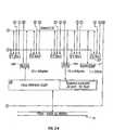
- a communication system 10includes a parallel, hardware-based multithreaded processor 12.
- the hardware-based multithreaded processor 12is coupled to a bus such as a PCI bus 14, a memory system 16 and a second bus 18.
- the system 10is especially useful for tasks that can be broken into parallel subtasks or functions.
- hardware-based multithreaded processor 12is useful for tasks that are bandwidth oriented rather than latency oriented.
- the hardware-based multithreaded processor 12has multiple microengines 22 each with multiple hardware controlled threads that can be simultaneously active and independently work on a task.
- the hardware-based multithreaded processor 12also includes a central controller 20 that assists in loading microcode control for other resources of the hardware-based multithreaded processor 12 and performs other general purpose computer type functions such as handling protocols, exceptions, extra support for packet processing where the microengines pass the packets off for more detailed processing such as in boundary conditions.
- the processor 20is a Strong Arm® (Arm is a trademark of ARM Limited, United Kingdom) based architecture.
- the general purpose microprocessor 20has an operating system. Through the operating system the processor 20 can call functions to operate on microengines 22a-22f.
- the processor 20can use any supported operating system preferably a real time operating system.
- operating systemssuch as, MicrosoftNT real-time, VXWorks and ⁇ CUS, a freeware operating system available over the Internet, can be used.
- the hardware-based multithreaded processor 12also includes a plurality of function microengines 22a-22f.
- Functional microengines (microengines) 22a-22feach maintain a plurality of program counters in hardware and states associated with the program counters. Effectively, a corresponding plurality of sets of threads can be simultaneously active on each of the microengines 22a-22f while only one is actually operating at any one time.
- microengines 22a-22fthere are six microengines 22a-22f as shown. Each microengines 22a-22f has capabilities for processing four hardware threads.
- the six microengines 22a-22foperate with shared resources including memory system 16 and bus interfaces 24 and 28.
- the memory system 16includes a Synchronous Dynamic Random Access Memory (SDRAM) controller 26a and a Static Random Access Memory (SRAM) controller 26b. SDRAM memory 16a and SDRAM controller 26a are typically used for processing large volumes of data, e.g., processing of network payloads from network packets.
- the SRAM controller 26b and SRAM memory 16bare used in a networking implementation for low latency, fast access tasks, e.g., accessing look-up tables, memory for the core processor 20, and so forth.
- the six microengines 22a-22faccess either the SDRAM 16a or SRAM 16b based on characteristics of the data. Thus, low latency, low bandwidth data is stored in and fetched from SRAM, whereas higher bandwidth data for which latency is not as important, is stored in and fetched from SDRAM.
- the microengines 22a-22fcan execute memory reference instructions to either the SDRAM controller 26a or SRAM controller 16b.
- SRAM or SDRAM memory accessescan be explained by SRAM or SDRAM memory accesses.
- an SRAM access requested by a Thread_0, from a microenginewill cause the SRAM controller 26b to initiate an access to the SRAM memory 16b.
- the SRAM controllercontrols arbitration for the SRAM bus, accesses the SRAM 16b, fetches the data from the SRAM 16b, and returns data to a requesting microengine 22a-22b.
- the microengine e.g., 22ahad only a single thread that could operate, that microengine would be dormant until data was returned from the SRAM.
- Thread_1can function while the first thread, e.g., Thread_0, is awaiting the read data to return.
- Thread_1may access the SDRAM memory 16a.
- Thread_1operates on the SDRAM unit, and Thread_0 is operating on the SRAM unit, a new thread, e.g., Thread_2 can now operate in the microengine 22a.
- Thread_2can operate for a certain amount of time until it needs to access memory or perform some other long latency operation, such as making an access to a bus interface. Therefore, simultaneously, the processor 12 can have a bus operation, SRAM operation and SDRAM operation all being completed or operated upon by one microengine 22a and have one more thread available to process more work in the data path.
- the hardware context swappingalso synchronizes completion of tasks. For example, two threads could hit the same shared resource e.g., SRAM.
- Each one of these separate functional units, e.g., the FBUS interface 28, the SRAM controller 26a, and the SDRAM controller 26b, when they complete a requested task from one of the microengine thread contextsreports back a flag signaling completion of an operation.
- the microenginecan determine which thread to turn on.
- the hardware-based multithreaded processor 12interfaces to network devices such as a media access controller device e.g., a 10/100BaseT Octal MAC 13a or a Gigabit Ethernet device 13b.
- a media access controller devicee.g., a 10/100BaseT Octal MAC 13a or a Gigabit Ethernet device 13b.
- the hardware-based multithreaded processor 12can interface to any type of communication device or interface that receives/sends large amounts of data.
- Communication system 10 functioning in a networking applicationcould receive a plurality of network packets from the devices 13a, 13b and process those packets in a parallel manner. With the hardware-based multithreaded processor 12, each network packet can be independently processed.
- processor 12is a print engine for a postscript processor or as a processor for a storage subsystem, i.e., RAID disk storage.
- a further useis as a matching engine.
- the advent of electronic tradingrequires the use of electronic matching engines to match orders between buyers and sellers. These and other parallel types of tasks can be accomplished on the system 10.
- the processor 12includes a bus interface 28 that couples the processor to the second bus 18.
- Bus interface 28in one embodiment couples the processor 12 to the so-called FBUS 18 (FIFO bus).
- the FBUS interface 28is responsible for controlling and interfacing the processor 12 to the FBUS 18.
- the FBUS 18is a 64-bit wide FIFO bus, used to interface to Media Access Controller (MAC) devices.
- MACMedia Access Controller
- the processor 12includes a second interface e.g., a PCI bus interface 24 that couples other system components that reside on the PCI 14 bus to the processor 12.
- the PCI bus interface 24provides a high speed data path 24a to memory 16 e.g., the SDRAM memory 16a. Through that path data can be moved quickly from the SDRAM 16a through the PCI bus 14, via direct memory access (DMA) transfers.
- the hardware based multithreaded processor 12supports image transfers.
- the hardware based multithreaded processor 12can employ a plurality of DMA channels so if one target of a DMA transfer is busy, another one of the DMA channels can take over the PCI bus to deliver information to another target to maintain high processor 12 efficiency.
- the PCI bus interface 24supports target and master operations.
- Target operationsare operations where slave devices on bus 14 access SDRAMs through reads and writes that are serviced as a slave to target operation.
- the processor core 20sends data directly to or receives data directly from the PCI interface 24.
- the hardware-based multithreaded processor 12also is constructed such that the sum of the bandwidths of the internal buses in the processor 12 exceed the bandwidth of external buses coupled to the processor 12.
- the processor 12includes an internal core processor bus 32, e.g., an ASB bus (Advanced System Bus) that couples the processor core 20 to the memory controller 26a, 26c and to an ASB translator 30 described below.
- the ASB busis a subset of the so called AMBA bus that is used with the Strong Arm processor core.
- the processor 12also includes a private bus 34 that couples the microengine units to SRAM controller 26b, ASB translator 30 and FBUS interface 28.
- a memory bus 38couples the memory controller 26a, 26b to the bus interfaces 24 and 28 and memory system 16 including flashrom 16c used for boot operations and so forth.
- each of the microengines 22a-22fincludes an arbiter that examines flags to determine the available threads to be operated upon. Any thread from any of the microengines 22a-22f can access the SDRAM controller 26a, SDRAM controller 26b or FBUS interface 28.
- the memory controllers 26a and 26beach include a plurality of queues to store outstanding memory reference requests. The queues either maintain order of memory references or arrange memory references to optimize memory bandwidth. For example, if a thread_0 has no dependencies or relationship to a thread_1, there is no reason that thread 1 and 0 cannot complete their memory references to the SRAM unit out of order.
- the microengines 22a-22fissue memory reference requests to the memory controllers 26a and 26b.
- the microengines 22a-22fflood the memory subsystems 26a and 26b with enough memory reference operations such that the memory subsystems 26a and 26b become the bottleneck for processor 12 operation.
- the processor 12can perform memory reference sorting.
- Memory reference sortingimproves achievable memory bandwidth.
- Memory reference sortingreduces dead time or a bubble that occurs with accesses to SRAM. With memory references to SRAM, switching current direction on signal lines between reads and writes produces a bubble or a dead time waiting for current to settle on conductors coupling the SRAM 16b to the SRAM controller 26b.
- Memory reference sortingallows the processor 12 to organize references to memory such that long strings of reads can be followed by long strings of writes. This can be used to minimize dead time in the pipeline to effectively achieve closer to maximum available bandwidth. Reference sorting helps maintain parallel hardware context threads. On the SDRAM, reference sorting allows hiding of pre-charges from one bank to another bank. Specifically, if the memory system 16b is organized into an odd bank and an even bank, while the processor is operating on the odd bank, the memory controller can start precharging the even bank. Precharging is possible if memory references alternate between odd and even banks.
- the processor 12By ordering memory references to alternate accesses to opposite banks, the processor 12 improves SDRAM bandwidth. Additionally, other optimizations can be used. For example, merging optimizations where operations that can be merged, are merged prior to memory access, open page optimizations where by examining addresses an opened page of memory is not reopened, chaining, as will be described below, and refreshing mechanisms, can be employed.
- the FBUS interface 28supports Transmit and Receive flags for each port that a MAC device supports, along with an Interrupt flag indicating when service is warranted.
- the FBUS interface 28also includes a controller 28a that performs header processing of incoming packets from the FBUS 18.
- the controller 28aextracts the packet headers and performs a microprogrammable source/destination/protocol hashed lookup (used for address smoothing) in SRAM. If the hash does not successfully resolve, the packet header is sent to the processor core 20 for additional processing.
- the FBUS interface 28supports the following internal data transactions:
- the FBUS 18is a standard industry bus and includes a data bus, e.g., 64 bits wide and sideband control for address and read/write control.
- the FBUS interface 28provides the ability to input large amounts of data using a series of input and output FIFO's 29a-29b. From the FIFOs 29a-29b, the microengines 22a-22f fetch data from or command the SDRAM controller 26a to move data from a receive FIFO in which data has come from a device on bus 18, into the FBUS interface 28. The data can be sent through memory controller 26a to SDRAM memory 16a, via a direct memory access. Similarly, the microengines can move data from the SDRAM 26a to interface 28, out to FBUS 18, via the FBUS interface 28.
- a command requestcan be a memory request or a FBUS request.
- a command requestcan move data from a register located in a microengine 22a to a shared resource, e.g., an SDRAM location, SRAM location, flash memory or some MAC address.
- the commandsare sent out to each of the functional units and the shared resources.
- the shared resourcesdo not need to maintain local buffering of the data. Rather, the shared resources access distributed data located inside of the microengines. This enables microengines 22a-22f, to have local access to data rather than arbitrating for access on a bus and risk contention for the bus. With this feature, there is a 0 cycle stall for waiting for data internal to the microengines 22a-22f.
- the data buses, e.g., ASB bus 30, SRAM bus 34 and SDRAM bus 38 coupling these shared resources, e.g., memory controllers 26a and 26bare of sufficient bandwidth such that there are no internal bottlenecks.
- the processor 12has an bandwidth requirement where each of the functional units is provided with at least twice the maximum bandwidth of the internal buses.
- the SDRAMcan run a 64 bit wide bus at 83 MHz.
- the SRAM data buscould have separate read and write buses, e.g., could be a read bus of 32 bits wide running at 166 MHz and a write bus of 32 bits wide at 166 MHz. That is, in essence, 64 bits running at 166 MHz which is effectively twice the bandwidth of the SDRAM.
- the core processor 20also can access the shared resources.
- the core processor 20has a direct communication to the SDRAM controller 26a to the bus interface 24 and to SRAM controller 26b via bus 32.
- the core processor 20access the microengines 22a-22f via the ASB Translator 30 over bus 34.
- the ASB translator 30can physically reside in the FBUS interface 28, but logically is distinct.
- the ASB Translator 30performs an address translation between FBUS microengine transfer register locations and core processor addresses (i.e., ASB bus) so that the core processor 20 can access registers belonging to the microengines 22a-22c.
- a scratchpad memory 27is also provided to permit microengines to write data out to the memory for other microengines to read.
- the scratchpad 27is coupled to bus 34.
- the processor core 20includes a RISC core 50 implemented in a five stage pipeline performing a single cycle shift of one operand or two operands in a single cycle, provides multiplication support and 32 bit barrel shift support.
- This RISC core 50is a standard Strong Army architecture but it is implemented with a five stage pipeline for performance reasons.
- the processor core 20also includes a 16 kilobyte instruction cache 52, an 8 kilobyte data cache 54 and a prefetch stream buffer 56.
- the core processor 20performs arithmetic operations in parallel with memory writes and instruction fetches.
- the core processor 20interfaces with other functional units via the ARM defined ASB bus.
- the ASB busis a 32-bit bidirectional bus 32.
- the microengineincludes a control store 70 which, in one implementation, includes a RAM of here 1,024 words of 32 bit.
- the RAMstores a microprogram.
- the microprogramis loadable by the core processor 20.
- the microengine 22falso includes controller logic 72.
- the controller logicincludes an instruction decoder 73 and program counter (PC) units 72a-72d.
- the four micro program counters 72a-72dare maintained in hardware.
- the microengine 22falso includes context event switching logic 74.
- Context event logic 74receives messages (e.g., SEQ_#_EVENT_RESPONSE; FBI_EVENT_RESPONSE; SRAM _EVENT_RESPONSE; SDRAM _EVENT_RESPONSE; and ASB _EVENT_RESPONSE) from each one of the shared resources, e.g., SRAM 26a, SDRAM 26b, or processor core 20, control and status registers, and so forth. These messages provide information on whether a requested function has completed. Based on whether or not a function requested by a thread has completed and signaled completion, the thread needs to wait for that completion signal, and if the thread is enabled to operate, then the thread is placed on an available thread list (not shown).
- the microengine 22fcan have a maximum of e.g., 4 threads available.
- the microengines 22In addition to event signals that are local to an executing thread, the microengines 22 employ signaling states that are global. With signaling states, an executing thread can broadcast a signal state to all microengines 22. Receive Request Available signal, Any and all threads in the microengines can branch on these signaling states. These signaling states can be used to determine availability of a resource or whether a resource is due for servicing.
- the context event logic 74has arbitration for the four (4) threads. In one embodiment, the arbitration is a round robin mechanism. Other techniques could be used including priority queuing or weighted fair queuing.
- the microengine 22falso includes an execution box (EBOX) data path 76 that includes an arithmetic logic unit 76a and general purpose register set 76b.
- the arithmetic logic unit 76aperforms arithmetic and logical functions as well as shift functions.
- the registers set 76bhas a relatively large number of general purpose registers. As will be described in FIG. 3B, in this implementation there are 64 general purpose registers in a first bank, Bank A and 64 in a second bank, Bank B.
- the general purpose registersare windowed as will be described so that they are relatively and absolutely addressable.
- the microengine 22falso includes a write transfer register stack 78 and a read transfer stack 80. These registers are also windowed so that they are relatively and absolutely addressable.
- Write transfer register stack 78is where write data to a resource is located.
- read register stack 80is for return data from a shared resource. Subsequent to or concurrent with data arrival, an event signal from the respective shared resource e.g., the SRAM controller 26a, SDRAM controller 26b or core processor 20 will be provided to context event arbiter 74 which will then alert the thread that the data is available or has been sent.
- Both transfer register banks 78 and 80are connected to the execution box (EBOX) 76 through a data path.
- the read transfer registerhas 64 registers and the write transfer register has 64 registers.
- the microengine datapathmaintains a 5-stage micro-pipeline 82.
- This pipelineincludes lookup of microinstruction words 82a, formation of the register file addresses 82b, read of operands from register file 82c, ALU, shift or compare operations 82d, and write-back of results to registers 82e.
- the microenginecan perform a simultaneous register file read and write, which completely hides the write operation.
- the SDRAM interface 26aprovides a signal back to the requesting microengine on reads that indicates whether a parity error occurred on the read request.
- the microengine microcodeis responsible for checking the SDRAM read Parity flag when the microengine uses any return data. Upon checking the flag, if it was set, the act of branching on it clears it. The Parity flag is only sent when the SDRAM is enabled for checking, and the SDRAM is parity protected.
- the microengines and the PCI Unitare the only requestors notified of parity errors. Therefore, if the processor core 20 or FIFO requires parity protection, a microengine assists in the request.
- the microengines 22a-22fsupport conditional branches.
- the worst case conditional branch latencyoccurs when the branch decision is a result of condition codes being set by the previous microcontrol instruction.
- the latencyis shown below in Table 1: 1 2 3 4 5 6 7 8 microstore lookup n1 cb n2 XX b1 b2 b3 b4 reg addr gen n1 cb XX XX b1 b2 b3 reg file lookup n1 cb XXXX b1 b2 ALU/shifter/cc n1 cb XXXX b1 write back m2 n1 cb XXXX where
- the microenginessupport deferred branches.
- Deferring branchesare when a microengine allows 1 or 2 microwords after the branch to occur before the branch takes effect (i.e. the effect of the branch is "deferred” in time). Thus, if useful work can be found to fill the wasted cycles after the branch microword, then the branch latency can be hidden.
- a 1-cycle deferred branchis shown below where n2 is allowed to execute after cb, but before b1: 1 2 3 4 5 6 7 8 microstore lookup n1 cb n2 XX b1 b2 b3 b4 reg addr gen n1 cb n2 XX b1 b2 b3 reg file lookup n1 cb n2 XX b1 b2 ALU/shifter/cc n1 cb n2 XX b1 write back n1 cb n2 XX
- a 2-cycle deferred branchis shown below, where n2 and n3 are both allowed to complete before the branch to b1 occurs. Note that a 2-cycle branch deferment is only allowed when the condition codes are set on the microword preceding the branch. 1 2 3 4 5 6 7 8 9 microstore lookup n1 cb n2 n3 b1 b2 b3 b4 b5 reg addr gen n1 cb n2 n3 b1 b2 b3 b4 reg file lkup n1 cb n2 n3 b1 b2 b3 ALU/shftr/cc n1 cb n2 n3 b1 b2 write back n1 cb n2 n3 b1
- the microenginesalso support condition code evaluation. If the condition codes upon which a branch decision are made are set 2 or more microwords before the branch, then 1 cycle of branch latency can be eliminated because the branch decision can be made 1 cycle earlier: 1 2 3 4 5 6 7 8 microstore lookup n1 n2 cb XX b1 b2 b3 b4 reg addr gen n1 n2 cb XX b1 b2 b3 reg file lookup n1 n2 cb XX b1 b2 ALU/shifter/cc n1 n2 cb XX b1 write back n1 n2 cb XX
- n1sets the condition codes and n2 does not set the conditions codes. Therefore, the branch decision can be made at cycle 4 (rather than 5), to eliminate 1 cycle of branch latency.
- the 1-cycle branch deferment and early setting of condition codesare combined to completely hide the branch latency:
- Condition codes (cc's)set 2 cycles before a 1-cycle deferred branch: 1 2 3 4 5 6 7 8 microstore lookup n1 n2 cb n3 b1 b2 b3 b4 reg addr gen n1 n2 cb n3 b1 b2 b3 reg file lookup n1 n2 cb n3 b1 b2 ALU/shifter/cc n1 n2 cb n3 b1 write back n1 n2 cb n3
- the microenginesupports branch guessing which attempts to reduce the 1 cycle of exposed branch latency that remains. By "guessing" the branch path or the sequential path, the microsequencer pre-fetches the guessed path 1 cycle before it definitely knows what path to execute.
- a context switchis a special form of a branch that causes a different context (and associated PC) to be selected. Context switching introduces some branch latency as well.
- Context switchingintroduces some branch latency as well.
- Conditional branches that operate on ALU condition codes which are set on the microword before the branchcan select 0, 1 or 2-cycle branch deferment modes.
- Condition codes set 2 or more microwords before the conditional branch that operates on themcan select 0 or 1-cycle branch deferment modes. All other branches (including context rearbitrations) can select either 0 or 1-cycle branch deferment modes.
- the architecturecould be designed to make a context arbitration microword within a branch deferment window of a preceding branch, jump or context arbitration microword, an illegal option. That is, in some embodiments, a context switch would not be allowed to occur during a branch transition in the pipeline because as mentioned, it could unduly complicate saving of the old context PC.
- the architecturecould also be designed to make branching within the branch deferment window of a preceding branch, jump or context arbitration microword illegal to avoid complicated and possible unpredictable branch behaviors.
- Each microengine 22a-22fsupports multi-threaded execution of four contexts.
- One reason for thisis to allow one thread to start executing just after another thread issues a memory reference and must wait until that reference completes before doing more work. This behavior is critical to maintaining efficient hardware execution of the microengines because memory latency is significant. Stated differently, if only a single thread execution was supported, the microengines would sit idle for a significant number of cycles waiting for references to return and thereby reduce overall computational throughput.
- Multi-threaded executionallows an microengines to hide memory latency by performing useful independent work across several threads. Two synchronization mechanisms are supplied in order to allow a thread to issue an SRAM or SDRAM reference, and then subsequently synchronize to the point in time when that reference completes.
- immediate Synchronizationthe microengine issues the reference and immediately swap out that context.
- the contextwill be signaled when the corresponding reference completes. Once signaled, the context will be swapped back in for execution when a context-swap event occurs and it is its turn to run.
- the microword after issuing the mem referencedoes not get executed until the reference completes.
- a second mechanismis Delayed Synchronization.
- the microengineissues the reference, and then continues to execute some other useful work independent of the reference. Some time later it could become necessary to synchronize the thread's execution stream to the completion of the issued reference before further work is performed. At this point a synchronizing microword is executed that will either swap out the current thread, and swap it back in sometime later when the reference has completed, or continue executing the current thread because the reference has already completed. Delayed synchronization is implemented using two different signaling schemes:
- the signal from which the thread is triggeredis generated when the corresponding transfer register valid bit is set or cleared. For example, an SRAM read which deposits data into transfer register A would be signaled when the valid bit for A is set. If the memory reference is associated with the transfer FIFO or the receive FIFO, instead of a transfer register, then the signal is generated when the reference completes in the SDRAM controller 26a. Only one signal state per context is held in the microengines scheduler, thus only one outstanding signal can exist in this scheme.
- microcontroller micro-programsThere are at least two general operational paradigms from which microcontroller micro-programs could be designed. One would be that overall microcontroller compute throughput and overall memory bandwidth are optimized at the expense of single thread execution latency. This paradigm would make sense when the system has multiple microengines executing multiple threads per microengine on unrelated data packets.
- a second oneis that microengine execution latency should be optimized at the expense of overall microengine compute throughput and overall memory bandwidth.
- This paradigmcould involve execution of a thread with a real-time constraint, that is, a constraint which dictates that some work must absolutely be done by some specified time. Such a constraint requires that optimization of the single thread execution be given priority over other considerations such as memory bandwidth or overall computational throughput.
- a real-time threadwould imply a single microengine that executes only one thread. Multiple threads would not be handled because the goal is to allow the single real-time thread to execute as soon as possible--execution of multiple threads would hinder this ability.
- optimization for throughput and bandwidthwould take a different approach. With optimization for microengine computational throughput and overall memory bandwidth less consideration is given to single thread execution latency. To accomplish this, the goal would be to equally space memory references across the microprogram for each thread. This would provide a uniform stream of memory references to the SRAM and SDRAM controllers and would maximize the probability that 1 thread is always available to hide the memory latency incurred when another thread is swapped out.
- the two register address spaces that existare Locally accessibly registers, and Globally accessible registers accessible by all microengines.
- Each bankis capable of performing a simultaneous read and write to two different words within its bank.
- the register set 76bis also organized into four windows 76b 0 -76b 3 of 32 registers that are relatively addressable per thread.
- thread_0will find its register 0 at 77a (register 0)
- the thread_1will find its register_0 at 77b (register 32)
- thread_2will find its register_0 at 77c (register 64)
- thread_3at 77d (register 96).
- Relative addressingis supported so that multiple threads can use the exact same control store and locations but access different windows of register and perform different functions.
- the uses of register window addressing and bank addressingprovide the requisite read bandwidth using only dual ported RAMS in the microengine 22f.
- windowed registersdo not have to save data from context switch to context switch so that the normal push and pop of a context swap file or stack is eliminated.
- Context switchinghere has a 0 cycle overhead for changing from one context to another.
- Relative register addressingdivides the register banks into windows across the address width of the general purpose register set. Relative addressing allows access any of the windows relative to the starting point of the window. Absolute addressing is also supported in this architecture where any one of the absolute registers may be accessed by any of the threads by providing the exact address of the register.
- registersare globally accessible from the microengines and the memory controllers:
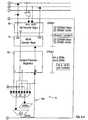
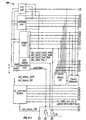
- the SDRAM memory controller 26aincludes memory reference queues 90 where memory reference requests arrive from the various microengines 22a-22f.
- the memory controller 26aincludes an arbiter 91 that selects the next the microengine reference requests to go to any of the functioning units. Given that one of the microengines is providing a reference request, the reference request will come through the address and command queue 90, inside the SDRAM controller 26a. If the reference request has a bit set called the "optimized MEM bit" the incoming reference request will be sorted into either the even bank queue 90a or the odd bank queue 90b. If the memory reference request does not have a memory optimization bit set, the default will be to go into an order queue 90c.
- the SDRAM controller 26is a resource which is shared among the FBUS interface 28, the core processor 20 and the PCI interface 24.
- the SDRAM controller 26also maintains a state machine for performing READ-MODIFY-Write atomic operations.
- the SDRAM controller 26also performs byte alignment for requests of data from SDRAM.
- the order queue 90cmaintains the order of reference requests from the microengines. With a series of odd and even banks references it may be required that a signal is returned only upon completion of a sequence of memory references to both the odd and even banks. If the microengine 22f sorts the memory references into odd bank and even bank references and one of the banks, e.g., the even bank is drained of memory references before the odd bank but the signal is asserted on the last even reference, the memory controller 26a could conceivably signal back to a microengine that the memory request had completed, even though the odd bank reference had not been serviced. This occurrence could cause a coherency problem. The situation is avoided by providing the order queue 90c allowing a microengine to have multiple memory references outstanding of which only its last memory reference needs to signal a completion.
- the SDRAM controller 26aalso includes a high priority queue 90d.
- a high priority queue 90dan incoming memory reference from one of the microengines goes directly to the high priority queue and is operated upon at a higher priority than other memory references in the other queues. All of these queues, the even bank queue 90a, the odd bank queue 90b, the order queue 90c and the high priority queue, are implemented in a single RAM structure that is logically segmented into four different windows, each window having its own head and tail pointer. Since filling and draining operations are only a single input and a single output, they can be placed into the same RAM structure to increase density of RAM structures.
- the SDRAM controller 26aalso includes core bus interface logic i.e., ASB bus 92.
- the ASB bus interface logic 92interfaces the core processor 20 to the SDRAM controller 26a.
- the ASB busis a bus that includes a 32 bit data path and a 28 bit address path.
- the datais accessed to and from memory through MEM ASB data device 98, e.g., a buffer.
- MEM ASB data device 98is a queue for write data. If there is incoming data from the core processor 20 via ASB interface 92, the data can be stored into the MEM ASB device 98 and subsequently removed from MEM ASB device 98 through the SDRAM interface 110 to SDRAM memory 16a. Although not shown, the same queue structure can be provided for the reads.
- the SDRAM controller 26aalso includes an engine 97 to pull data from the microengines and PCI bus.
- Additional queuesinclude the PCI address queue 94 and ASB read/write queue 96 that maintain a number of requests.
- the memory requestsare sent to SDRAM interface 110 via multiplexer 106.
- the multiplexer 106is controlled by the SDRAM arbiter 91 which detects the fullness of each of the queues and the status of the requests and from that decides priority based on a programmable value stored in a priority service control register 100.
- bus 112is actually two separate buses instead of a single bus. The separate buses would include a read bus coupling the distributed microengines 22a-22f and a write bus coupling the distributed microengines 22a-22f.
- a feature of the SDRAM controller 26ais that when a memory reference is stored in the queues 90, in addition to the optimized MEM bit that can be set, there is a "chaining bit".
- the chaining bitwhen set allows for special handling of contiguous memory references.
- the arbiter 12controls which microengine will be selected to provide memory reference requests over the commander bus to queue 90 (FIG. 4). Assertion of the chain bit will control the arbiter to have the arbiter select the functional unit which previously requested that bus because setting of the chain bit indicates that the microengine issued a chain request.
- Contiguous memory referenceswill be received in queue 90 when the chaining bit is set. Those contiguous references will typically be stored in the order queue 90c because the contiguous memory references are multiple memory references from a single thread.
- the memory controller 26aneed only signal at the end of the chained memory references when done.
- the memory referencescould go into different banks and potentially complete on one of the banks issuing the signal "done" before the other bank was fully drained, thus destroying coherency. Therefore, the chain bit is used by the controller 110 to maintain the memory references from the current queue.
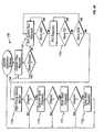
- the arbitration policyfavors chained microengine memory requests.
- the process 115starts by examining for Chained microengine memory reference requests 115a .
- the process 115stays at the chained requests until the chain bit is cleared.
- the processexamines ASB bus requests 115b followed by PCI bus requests 115c, High Priority Queue Service 115d, Opposite Bank Requests 115e, Order Queue Requests 115f, and Same Bank Requests 115g. Chained request are serviced completely, whereas services 115b-115d are serviced in round robin order.
- FIG. 4Btypical timing of a memory without active memory optimization and with active memory optimization is shown.
- the use of active memory optimizationsmaximizes the use of the bus and thus hides the inherent latency within physical SDRAM devices.
- a non-optimized accesscan take 14 cycles while optimized access can take 7 cyles.
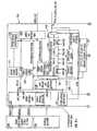
- the memory controller 26b for the SRAMincludes an address and command queue 120. While the memory controller 26a (FIG. 4) has a queue for memory optimization based on odd and even banking, memory controller 26b is optimized based on the type of memory operation, i.e., a read or a write.
- the address and command queue 120includes a high priority queue 120a, a read queue 120b which is the predominant memory reference function that an SRAM performs, and an order queue 120c which in general will include all writes to SRAM and reads that are to be non-optimized. Although not shown, the address and command queue 120 could also include a write queue.
- the SRAM controller 26balso includes core bus interface logic i.e., ASB bus 122.
- the ASB bus interface logic 122interfaces the core processor 20 to the SRAM controller 26b.
- the ASB busis a bus that includes a 32 bit data path and a 28 bit address path.
- the datais accessed to and from memory through MEM ASB data device 128, e.g., a buffer.
- MEM ASB data device 128is a queue for write data. If there is incoming data from the core processor 20 via ASB interface 122, the data can be stored into the MEM ASB device 128 and subsequently removed from MEM ASB device 128 through SRAM interface 140 to SRAM memory 16b. Although not shown, the same queue structure can be provided for reads.
- the SRAM controller 26balso includes an engine 127 to pull data from the microengines and PCI bus.
- the memory requestsare sent to SRAM interface 140 via multiplexer 126.
- the multiplexer 126is controlled by the SRAM arbiter 131 which detects the fullness of each of the queues and the status of the requests and from that decides priority based on a programmable value stored in a priority service control register 130. Once control to the multiplexer 126 selects a memory reference request, the memory reference request, is sent to a decoder 138 where it is decoded and an address is generated.
- the SRAM Unitmaintains control of the Memory Mapped off-chip SRAM and Expansion ROM.
- the SRAM controller 26bcan address, e.g., 16 MBytes, with, e.g., 8 MBytes mapped for SRAM 16b, and 8 MBytes reserved for special functions including: Boot space via flashrom 16c; and Console port access for MAC devices 13a, 13b and access to associated (RMON) counters.
- the SRAMis used for local look-up tables and queue management functions.
- the SRAM controller 26bsupports the following transactions:
- the SRAM controller 26bperforms memory reference sorting to minimize delays (bubbles) in the pipeline from the SRAM interface 140 to memory 16b.
- the SRAM controller 26bdoes memory reference sorting based on the read function.
- a bubblecan either be 1 or 2 cycles depending on the type of memory device employed.
- the SRAM controller 26bincludes a lock lookup device 142 which is an eight (8 entry address content addressable memory for look-ups of read locks. Each position include a valid bit that is examined by subsequent read-lock requests.
- the address and command queue 120also includes a Read Lock Fail Queue 120d.
- the Read Lock Fail Queue 120dis used to hold read memory reference requests that fail because of a lock existing on a portion of memory. That is, one of the microengines issues a memory request that has a read lock request that is processed in address and control queue 120. The memory request will operate on either the order queue 120c or the read queue 120b and will recognize it as a read lock request.
- the controller 26bwill access lock lookup device 142 to determine whether this memory location is already locked.
- this memory lock requestwill fail and will be stored in the read lock fail queue 120d. If it is unlocked or if 142 shows no lock on that address, then the address of that memory reference will be used by the SRAM interface 140 to perform a traditional SRAM address read/write request to memory 16b.
- the command controller and address generator 138will also enter the lock into the lock look up device 142 so that subsequent read lock requests will find the memory location locked.
- a memory locationis unlocked by operation of the a microcontrol instruction in a program after the need for the lock has ended. The location is unlocked by clearing the valid bit in the CAM. After an unlock, the read lock fail queue 120d becomes the highest priority queue giving all queued read lock misses, a chance to issue a memory lock request.
- FIG. 5Atypical timing of a static random access memory without active memory optimization and with active memory optimization is shown. As can be seen, grouping reads and writes improves cycletime eliminating dead cycles.
- the FBUS interface 28 in a network applicationcan performs header processing of incoming packets from the FBUS 18.
- a key function which the FBUS interface performsis extraction of packet headers, and a microprogrammable source/destination/protocol hashed lookup in SRAM. If the hash does not successfully resolve, the packet header is promoted to the core processor 28 for more sophisticated processing.
- the FBI 28contains a Transmit FIFO 182, a Receive FIFO 183, a HASH unit 188 and FBI control and status registers 189. These four units communicate with the microengines 22, via a time-multiplexed access to the SRAM bus 38 which is connected to the transfer registers 78, 80 in the microengines. That is, all communications to and from the microengines are via the transfer registers 78, 80.
- the FBUS interface 28includes a push state machine 200 for pushing data into the transfer registers during the time cycles which the SRAM is NOT using the SRAM data bus (part of bus 38) and a pull state machine 202 for fetching data from the transfer registers in the respective microengine.
- the Hashing unitincludes a pair of FIFO's 188a, 188b.
- the hash unitdetermines that the FBI 28 received an FBI_hash request.
- the hash unit 188fetches hash keys from the calling microengine 22. After the keys are fetched and hashed, the indices are delivered back to the calling microengine 22. Up to three hashes are performed under a single FBI_hash request.
- the busses 34 and 38are each unidirectional: SDRAM_push/pull_data, and Sbus_push/pull_data. Each of these busses require control signals which will provide read/write controls to the appropriate microengine 22 Transfer registers.
- transfer registersrequire protection from the context controlling them to guarantee read correctness.
- thread_1if a write transfer register is being used by a thread_1 to provide data to the SDRAM 16a, thread_1 must not overwrite this register until the signal back from SDRAM controller 26a indicates that this register has been promoted and may now be re-used. Every write does not require a signal back from the destination indicating that the function has been completed, because if the thread writes to the same command queue at that destination with multiple requests, the order of the completion is guaranteed within that command queue, thus only the last command requires the signaling back to the thread.
- the threaduses multiple command queues (order and read), then these command requests must be broken into separate context tasks, so that ordering is maintained via context swapping.
- the exception case indicated at the beginning of this paragraphis relative to a certain class of operations using an unsolicited PUSH to transfer registers from the FBI for FBUS status information.
- the FBIprovides a special Push_protect signal when these special FBI push operations are set up.
- Any microengine 22 that uses the FBI unsolicited push techniquemust test the protection flag prior to accessing the FBUS interface/microengine agreed upon transfer registers. If the flag is not asserted, then the transfer registers may be accessed by the microengine. If the flag is Asserted then the context should wait N cycles prior to accessing the registers. A priori this count is determined by the number of transfer registers being pushed, plus a frontend protection window. The basic idea is that the microengine must test this flag then quickly move the data which it wishes to read from the read transfer registers to GPR's in contiguous cycles, so the push engine does not collide with the microengine read.
Landscapes
- Engineering & Computer Science (AREA)
- Theoretical Computer Science (AREA)
- Software Systems (AREA)
- Physics & Mathematics (AREA)
- General Engineering & Computer Science (AREA)
- General Physics & Mathematics (AREA)
- Computer Hardware Design (AREA)
- Multimedia (AREA)
- Computing Systems (AREA)
- Multi Processors (AREA)
- Image Processing (AREA)
- Bus Control (AREA)
Abstract
Description
FBI_EVENT_RESPONSE; SRAM _EVENT_RESPONSE; SDRAM
_EVENT_RESPONSE; and ASB _EVENT_RESPONSE) from each one of the shared resources, e.g.,
| 1 | 2 | 3 | 4 | 5 | 6 | 7 | 8 | |
| microstore lookup | n1 | cb | n2 | XX | b1 | b2 | b3 | b4 |
| reg addr gen | n1 | cb | XX | XX | b1 | b2 | b3 | |
| reg file lookup | n1 | cb | XX | XX | b1 | b2 | ||
| ALU/shifter/cc | n1 | cb | XX | XX | b1 | |||
| write back | m2 | n1 | cb | XX | XX |
| 1 | 2 | 3 | 4 | 5 | 6 | 7 | 8 | |
| microstore lookup | n1 | cb | n2 | XX | b1 | b2 | b3 | b4 |
| reg addr gen | n1 | cb | n2 | XX | b1 | b2 | b3 | |
| reg file lookup | n1 | cb | n2 | XX | b1 | b2 | ||
| ALU/shifter/cc | n1 | cb | n2 | XX | b1 | |||
| write back | n1 | cb | n2 | XX |
| 1 | 2 | 3 | 4 | 5 | 6 | 7 | 8 | 9 | |
| microstore lookup | n1 | cb | n2 | n3 | b1 | b2 | b3 | b4 | b5 |
| reg addr gen | n1 | cb | n2 | n3 | b1 | b2 | b3 | b4 | |
| reg file lkup | n1 | cb | n2 | n3 | b1 | b2 | b3 | ||
| ALU/shftr/cc | n1 | cb | n2 | n3 | b1 | b2 | |||
| write back | n1 | cb | n2 | n3 | b1 |
| 1 | 2 | 3 | 4 | 5 | 6 | 7 | 8 | |
| microstore lookup | n1 | n2 | cb | XX | b1 | b2 | b3 | b4 |
| reg addr gen | n1 | n2 | cb | XX | b1 | b2 | b3 | |
| reg file lookup | n1 | n2 | cb | XX | b1 | b2 | ||
| ALU/shifter/cc | n1 | n2 | cb | XX | b1 | |||
| write back | n1 | n2 | cb | XX |
Condition codes (cc's) set 2 cycles before a 1-cycledeferred branch:
| 1 | 2 | 3 | 4 | 5 | 6 | 7 | 8 | |
| microstore lookup | n1 | n2 | cb | n3 | b1 | b2 | b3 | b4 |
| reg addr gen | n1 | n2 | cb | n3 | b1 | b2 | b3 | |
| reg file lookup | n1 | n2 | cb | n3 | b1 | b2 | ||
| ALU/shifter/cc | n1 | n2 | cb | n3 | b1 | |||
| write back | n1 | n2 | cb | n3 |
guess branch taken /branch is taken
| 1 | 2 | 3 | 4 | 5 | 6 | 7 | 8 | |
| microstore lookup | n1 | cb | n1 | b1 | b2 | b3 | b4 | b5 |
| reg addr gen | n1 | cb | XX | b1 | b2 | b3 | b4 | |
| reg file lookup | n1 | cb | XX | b1 | b2 | b3 | ||
| ALU/shifter/cc | n1 | cb | XX | b1 | b2 | |||
| write back | n1 | cb | XX | b1 |
guess branch taken /branch is NOT taken
| 1 | 2 | 3 | 4 | 5 | 6 | 7 | 8 | |
| microstore lookup | n1 | cb | n1 | XX | n2 | n3 | n4 | n5 |
| reg addr gen | n1 | cb | n1 | XX | n2 | n3 | n4 | |
| reg file lookup | n1 | cb | n1 | XX | n2 | n3 | ||
| ALU/shifter/cc | n1 | cb | n1 | XX | n2 | |||
| write back | n1 | cb | n1 | XX |
| 1 | 2 | 3 | 4 | 5 | 6 | 7 | 8 | |
| microstore lookup | n1 | cb | n1 | n2 | n3 | n4 | n5 | n6 |
| reg addr gen | n1 | cb | n1 | n2 | n3 | n4 | n5 | |
| reg file lookup | n1 | cb | n1 | n2 | n1 | b4 | ||
| ALU/shifter/cc | n1 | cb | n1 | n2 | n3 | |||
| write back | n1 | cb | n1 | n2 |
| 1 | 2 | 3 | 4 | 5 | 6 | 7 | 8 | |
| microstore lookup | n1 | cb | n1 | XX | b1 | b2 | b3 | b4 |
| reg addr gen | n1 | cb | XX | XX | b1 | b2 | b3 | |
| reg file lookup | n1 | cb | XX | XX | b1 | b2 | ||
| ALU/shifter/cc | n1 | cb | XX | XX | b1 | |||
| write back | n1 | cb | XX | XX |
| 1 | 2 | 3 | 4 | 5 | 6 | 7 | 8 | |
| microstore lookup | n1 | cb | n2 | b1 | b2 | b3 | b4 | b5 |
| reg addr gen | n1 | cb | n2 | b1 | b2 | b3 | b4 | |
| reg file lookup | n1 | cb | n2 | b1 | b2 | b3 | ||
| ALU/shifter/cc | n1 | cb | n2 | b1 | b2 | |||
| write back | n1 | cb | n2 | b1 |
guess branch taken with 1-cycle deferred branch/branch isNOT taken
| 1 | 2 | 3 | 4 | 5 | 6 | 7 | 8 | 9 | |
| microstore lookup | n1 | cb | n2 | XX | n3 | n4 | n5 | n6 | n7 |
| reg addr gen | n1 | cb | n2 | XX | n3 | n4 | n5 | n6 | |
| reg file lookup | n1 | cb | n2 | XX | n3 | n4 | n5 | ||
| ALU/shifter/cc | n1 | cb | n2 | XX | n3 | n4 | |||
| write back | n1 | cb | n2 | XX | n3 |
guess branch NOT taken/branch is taken
| 1 | 2 | 3 | 4 | 5 | 6 | 7 | 8 | 9 | |
| microstore lookup | n1 | cb | n2 | XX | b1 | b2 | b3 | b4 | b5 |
| reg addr gen | n1 | cb | n2 | XX | b1 | b2 | b3 | b4 | |
| reg file lkup | n1 | cb | n2 | XX | b1 | b2 | b3 | ||
| ALU/shftr/cc | n1 | cb | n2 | XX | b1 | b2 | |||
| write back | n1 | cb | n2 | XX | b1 | ||||
| where nx is pre-branch microword (n1 sets cc's) cb is conditional branch bx is post-branch microword XX is aborted microword |
| 1 | 2 | 3 | 4 | 5 | 6 | 7 | 8 | 9 | |
| microstore lookup | n1 | jp | XX | XX | XX | j1 | j2 | j3 | j4 |
| reg addr gen | n1 | jp | XX | XX | XX | j1 | j2 | j3 | |
| reg file lkup | n1 | jp | XX | XX | XX | j1 | j2 | ||
| ALU/shftr/cc | n1 | jp | XX | XX | XX | j1 | |||
| write back | n1 | jp | XX | XX | XX |
| 1 | 2 | 3 | 4 | 5 | 6 | 7 | 8 | 9 | |
| microstore lookup | ol | ca | br | n1 | n2 | n3 | n4 | n5 | n6 |
| reg addr gen | ol | ca | XX | n1 | n2 | n3 | n4 | n5 | |
| reg file lkup | ol | ca | XX | n1 | n2 | n3 | n4 | ||
| ALU/shftr/cc | ol | ca | XX | n1 | n2 | n3 | |||
| write back | ol | ca | XX | n1 | n2 | ||||
| where ox is old context flow br is branch microword in old context ca is context rearbitration (causes context switch) nx is new context flow XX is aborted microword |
issue mem ref 1issue mem ref 2issue mem ref 3- perform work independent of
mem refs - synch to completion of
mem ref 1 - perform work dependent on
mem ref 1 and independent ofmem ref - issue any new mem refs based on preceding work.
- synch to completion of
mem ref 2 - perform work dependent on
mem ref mem ref 3 - issue any new mem refs based on preceding work.
- synch to completion of
mem ref 3 - perform work dependent on the completion of all 3 refs
- issue any new mem refs based on preceding work.
| 7 | 6 | 5 | 4 | 3 | 2 | 1 | 0 | ||
| A | a6 | 0 | a5 | a4 | a3 | a2 | a1 | a0 | |
| b6 | 1 | b5 | b4 | b3 | b2 | b1 | b0 | ||
| SRAM/ASB | a5 | a4 | 0 | a3 | a2 | a1 | a0 | ||
| SDRAM | a5 | a4 | 0 | a3 | a2 | a1 | a0 | ||
| a6=0 b6=0 a6=1, a5=0, a4=0 a6=1, a5=0, a4=1 |
| 7 | 6 | 5 | 4 | 3 | 2 | 1 | 0 | |
| A GPR | d7 | d6 | d5 | d4 | d3 | d2 | d1 | d0 |
| B GPR | d7 | d6 | d5 | d4 | d3 | d2 | d1 | d0 |
| SRAM/ASB | d7 | d6 | d5 | d4 | d3 | d2 | d1 | d0 |
| SDRAM | d7 | d6 | d5 | d4 | d3 | d2 | d1 | d0 |
| d7=0, d6=0 d7=0, d6=1 d7=1,d6=0, d5=0 d7=1, d6=0, d5=1 |
| 7 | 6 | 5 | 4 | 3 | 2 | 1 | 0 | |
| A | a4 | 0 | context | a31 | a2 | a1 | a0 | |
| b4 | 1 | context | b3 | b2 | b1 | b0 | ||
| SRAM/ | ab4 | 0 | ab3 | context | b2 | b1 | ||
| SDRAM | ab4 | |||||||
| 0 | ab3 | context | b2 | b1 | ab0 | |||
| a4=0 b4=0 ab4=1, ab3=0 ab4=1, ab3=1 |
| 7 | 6 | 5 | 4 | 3 | 2 | 1 | 0 | |
| A GPR | d5 | d4 | context | d3 | d2 | d1 | d0 | |
| B GPR | d5 | d4 | context | d3 | d2 | d1 | d0 | |
| SRAM/ASB | d5 | d4 | d3 | context | d2 | d1 | d0 | |
| SDRAM | d5 | d4 | d3 | context | d2 | d1 | d0 | |
| d5=0, d4=0 d5=0, d4=1 d5=1, d4=0, d3=0 d5=1, d4=0, d3=1 |
Claims (19)
- A parallel hardware-based multithreaded processorcomprises (12):a plurality of microengines (22) that eachsupport multiple hardware threads; anda general purpose processor (20) thatcoordinates system functions including functions to operateon the microengines.
- The processor of claim 1 wherein the general purposeprocessor load microcontrol programs in the plurality ofmicrocontrol engines.
- The processor of claim 1 further comprising a memorycontrol system.
- The processor of claim 1, 2 or 3 wherein the memorycontrol system comprises a first memory controller thatsorts memory references based on whether the memoryreferences are directed to an even bank or an odd bank ofmemory.
- The processor of any of claims 1 to 4 wherein thememory control system comprises a second memory controllerthat optimizes memory references based upon whether thememory references are read references or write references.
- The processor of claim 1 wherein each of the pluralityof microengines employ hardware-based context swappingamongst a plurality of threads that are independentlyexecutable within each of the microengines.
- The processor of claim 1 further comprising a highspeed bus interface that couples the processor to acommunication bus.
- The processor of claim 1 further comprising a businterface that couples the processor to a computer systembus.
- The processor of claim 1 further comprising aninternal bus arrangement to couple shared resources in theprocessor to the plurality of microengines.
- The processor of claim 9 wherein the internal busarrangement to couple shared resources, comprises:a first bus to couple the general purposeprocessor to the plurality of microengines.
- The processor of claim 9 wherein the internal busarrangement to couple shared resources, comprises:a translator device that translates requests fromthe general purpose processor to the microengines; anda first bus to couple the general purposeprocessor to the plurality of microengines.
- The processor of claim 3 wherein the internal busarrangement to couple shared resources, comprises:a translator device that translates requests fromthe general purpose processor to the microengines; anda first bus to couple the general purposeprocessor to the plurality of microengines; anda second bus to couple the general purposeprocessor to the memory control system.
- The processor of claim 11, further comprising a thirdbus to couple the microengines to external bus interfaces.
- The processor of claim 8 wherein the shared resourcescomprise:a memory controller for controlling access to lowlatency memory;a memory controller for controlling an access tohigh bandwidth memory;a bus interface for controlling access to acommunications bus; anda bus interface for controlling access to acomputer bus.
- The processor of claim 1 wherein each one of themicroengines includes a program counter to uniquelyidentify a position of a thread during execution in themicroengine.
- The processor of claim 1 wherein the processorsupports global signaling to each of the microengines.
- The processor of claim 16 wherein the global signalingis available to each thread in each microengine.
- The processor of claim 17 wherein the global signalingis available to each thread to permit each thread to take abranch.
- The parallel hardware-based multithreaded processor ofclaim 5 when appendant claim 4 wherein the first memorycontroller controls synchronous dynamic random accessmemory and the second memory controller controls staticrandom access static memory.
Applications Claiming Priority (3)
| Application Number | Priority Date | Filing Date | Title |
|---|---|---|---|
| US387111 | 1982-06-10 | ||
| US09/387,111US6606704B1 (en) | 1999-08-31 | 1999-08-31 | Parallel multithreaded processor with plural microengines executing multiple threads each microengine having loadable microcode |
| PCT/US2000/022322WO2001016782A2 (en) | 1999-08-31 | 2000-08-15 | Parallel processor architecture |
Publications (2)
| Publication Number | Publication Date |
|---|---|
| EP1221105A2 EP1221105A2 (en) | 2002-07-10 |
| EP1221105B1true EP1221105B1 (en) | 2003-10-29 |
Family
ID=23528511
Family Applications (1)
| Application Number | Title | Priority Date | Filing Date |
|---|---|---|---|
| EP00954073AExpired - LifetimeEP1221105B1 (en) | 1999-08-31 | 2000-08-15 | Parallel processor architecture |
Country Status (9)
| Country | Link |
|---|---|
| US (2) | US6606704B1 (en) |
| EP (1) | EP1221105B1 (en) |
| CN (1) | CN1185592C (en) |
| AT (1) | ATE253238T1 (en) |
| AU (1) | AU6641900A (en) |
| CA (1) | CA2391833C (en) |
| DE (1) | DE60006270T2 (en) |
| HK (1) | HK1049716B (en) |
| WO (1) | WO2001016782A2 (en) |
Families Citing this family (130)
| Publication number | Priority date | Publication date | Assignee | Title |
|---|---|---|---|---|
| US7266725B2 (en) | 2001-09-03 | 2007-09-04 | Pact Xpp Technologies Ag | Method for debugging reconfigurable architectures |
| DE19651075A1 (en) | 1996-12-09 | 1998-06-10 | Pact Inf Tech Gmbh | Unit for processing numerical and logical operations, for use in processors (CPU's), multi-computer systems, data flow processors (DFP's), digital signal processors (DSP's) or the like |
| DE19654595A1 (en) | 1996-12-20 | 1998-07-02 | Pact Inf Tech Gmbh | I0 and memory bus system for DFPs as well as building blocks with two- or multi-dimensional programmable cell structures |
| US6542998B1 (en) | 1997-02-08 | 2003-04-01 | Pact Gmbh | Method of self-synchronization of configurable elements of a programmable module |
| US8686549B2 (en)* | 2001-09-03 | 2014-04-01 | Martin Vorbach | Reconfigurable elements |
| DE19861088A1 (en) | 1997-12-22 | 2000-02-10 | Pact Inf Tech Gmbh | Repairing integrated circuits by replacing subassemblies with substitutes |
| WO2000077652A2 (en) | 1999-06-10 | 2000-12-21 | Pact Informationstechnologie Gmbh | Sequence partitioning in cell structures |
| US6427196B1 (en) | 1999-08-31 | 2002-07-30 | Intel Corporation | SRAM controller for parallel processor architecture including address and command queue and arbiter |
| US6668317B1 (en) | 1999-08-31 | 2003-12-23 | Intel Corporation | Microengine for parallel processor architecture |
| US6983350B1 (en) | 1999-08-31 | 2006-01-03 | Intel Corporation | SDRAM controller for parallel processor architecture |
| US7546444B1 (en) | 1999-09-01 | 2009-06-09 | Intel Corporation | Register set used in multithreaded parallel processor architecture |
| AU7098600A (en) | 1999-09-01 | 2001-03-26 | Intel Corporation | Instruction for multithreaded parallel processor |
| US7191309B1 (en) | 1999-09-01 | 2007-03-13 | Intel Corporation | Double shift instruction for micro engine used in multithreaded parallel processor architecture |
| US6532509B1 (en) | 1999-12-22 | 2003-03-11 | Intel Corporation | Arbitrating command requests in a parallel multi-threaded processing system |
| US6694380B1 (en) | 1999-12-27 | 2004-02-17 | Intel Corporation | Mapping requests from a processing unit that uses memory-mapped input-output space |
| US6631430B1 (en)* | 1999-12-28 | 2003-10-07 | Intel Corporation | Optimizations to receive packet status from fifo bus |
| US7620702B1 (en) | 1999-12-28 | 2009-11-17 | Intel Corporation | Providing real-time control data for a network processor |
| US6625654B1 (en) | 1999-12-28 | 2003-09-23 | Intel Corporation | Thread signaling in multi-threaded network processor |
| US6307789B1 (en) | 1999-12-28 | 2001-10-23 | Intel Corporation | Scratchpad memory |
| US6661794B1 (en) | 1999-12-29 | 2003-12-09 | Intel Corporation | Method and apparatus for gigabit packet assignment for multithreaded packet processing |
| US6952824B1 (en) | 1999-12-30 | 2005-10-04 | Intel Corporation | Multi-threaded sequenced receive for fast network port stream of packets |
| US7480706B1 (en) | 1999-12-30 | 2009-01-20 | Intel Corporation | Multi-threaded round-robin receive for fast network port |
| US6976095B1 (en) | 1999-12-30 | 2005-12-13 | Intel Corporation | Port blocking technique for maintaining receive packet ordering for a multiple ethernet port switch |
| US6584522B1 (en) | 1999-12-30 | 2003-06-24 | Intel Corporation | Communication between processors |
| US6898179B1 (en)* | 2000-04-07 | 2005-05-24 | International Business Machines Corporation | Network processor/software control architecture |
| EP2226732A3 (en) | 2000-06-13 | 2016-04-06 | PACT XPP Technologies AG | Cache hierarchy for a multicore processor |
| US7681018B2 (en) | 2000-08-31 | 2010-03-16 | Intel Corporation | Method and apparatus for providing large register address space while maximizing cycletime performance for a multi-threaded register file set |
| US8058899B2 (en) | 2000-10-06 | 2011-11-15 | Martin Vorbach | Logic cell array and bus system |
| US7020871B2 (en) | 2000-12-21 | 2006-03-28 | Intel Corporation | Breakpoint method for parallel hardware threads in multithreaded processor |
| US7131125B2 (en)* | 2000-12-22 | 2006-10-31 | Nortel Networks Limited | Method and system for sharing a computer resource between instruction threads of a multi-threaded process |
| US7444531B2 (en) | 2001-03-05 | 2008-10-28 | Pact Xpp Technologies Ag | Methods and devices for treating and processing data |
| US7844796B2 (en) | 2001-03-05 | 2010-11-30 | Martin Vorbach | Data processing device and method |
| US9037807B2 (en) | 2001-03-05 | 2015-05-19 | Pact Xpp Technologies Ag | Processor arrangement on a chip including data processing, memory, and interface elements |
| US7996827B2 (en) | 2001-08-16 | 2011-08-09 | Martin Vorbach | Method for the translation of programs for reconfigurable architectures |
| US7216204B2 (en) | 2001-08-27 | 2007-05-08 | Intel Corporation | Mechanism for providing early coherency detection to enable high performance memory updates in a latency sensitive multithreaded environment |
| US6868476B2 (en) | 2001-08-27 | 2005-03-15 | Intel Corporation | Software controlled content addressable memory in a general purpose execution datapath |
| US7487505B2 (en) | 2001-08-27 | 2009-02-03 | Intel Corporation | Multithreaded microprocessor with register allocation based on number of active threads |
| US7225281B2 (en)* | 2001-08-27 | 2007-05-29 | Intel Corporation | Multiprocessor infrastructure for providing flexible bandwidth allocation via multiple instantiations of separate data buses, control buses and support mechanisms |
| US7434191B2 (en) | 2001-09-03 | 2008-10-07 | Pact Xpp Technologies Ag | Router |
| US8686475B2 (en) | 2001-09-19 | 2014-04-01 | Pact Xpp Technologies Ag | Reconfigurable elements |
| US7126952B2 (en) | 2001-09-28 | 2006-10-24 | Intel Corporation | Multiprotocol decapsulation/encapsulation control structure and packet protocol conversion method |
| US7676588B2 (en)* | 2001-10-05 | 2010-03-09 | International Business Machines Corporation | Programmable network protocol handler architecture |
| US7072970B2 (en)* | 2001-10-05 | 2006-07-04 | International Business Machines Corporation | Programmable network protocol handler architecture |
| US7158964B2 (en) | 2001-12-12 | 2007-01-02 | Intel Corporation | Queue management |
| US7107413B2 (en) | 2001-12-17 | 2006-09-12 | Intel Corporation | Write queue descriptor count instruction for high speed queuing |
| US7269179B2 (en) | 2001-12-18 | 2007-09-11 | Intel Corporation | Control mechanisms for enqueue and dequeue operations in a pipelined network processor |
| US7895239B2 (en) | 2002-01-04 | 2011-02-22 | Intel Corporation | Queue arrays in network devices |
| US7181573B2 (en) | 2002-01-07 | 2007-02-20 | Intel Corporation | Queue array caching in network devices |
| US6934951B2 (en) | 2002-01-17 | 2005-08-23 | Intel Corporation | Parallel processor with functional pipeline providing programming engines by supporting multiple contexts and critical section |
| DE10392560D2 (en) | 2002-01-19 | 2005-05-12 | Pact Xpp Technologies Ag | Reconfigurable processor |
| US7610451B2 (en)* | 2002-01-25 | 2009-10-27 | Intel Corporation | Data transfer mechanism using unidirectional pull bus and push bus |
| US7181594B2 (en) | 2002-01-25 | 2007-02-20 | Intel Corporation | Context pipelines |
| US7149226B2 (en) | 2002-02-01 | 2006-12-12 | Intel Corporation | Processing data packets |
| US8127061B2 (en) | 2002-02-18 | 2012-02-28 | Martin Vorbach | Bus systems and reconfiguration methods |
| US8914590B2 (en) | 2002-08-07 | 2014-12-16 | Pact Xpp Technologies Ag | Data processing method and device |
| US7437724B2 (en)* | 2002-04-03 | 2008-10-14 | Intel Corporation | Registers for data transfers |
| US7471688B2 (en) | 2002-06-18 | 2008-12-30 | Intel Corporation | Scheduling system for transmission of cells to ATM virtual circuits and DSL ports |
| US7657861B2 (en) | 2002-08-07 | 2010-02-02 | Pact Xpp Technologies Ag | Method and device for processing data |
| US20070083730A1 (en)* | 2003-06-17 | 2007-04-12 | Martin Vorbach | Data processing device and method |
| AU2003286131A1 (en) | 2002-08-07 | 2004-03-19 | Pact Xpp Technologies Ag | Method and device for processing data |
| US7337275B2 (en) | 2002-08-13 | 2008-02-26 | Intel Corporation | Free list and ring data structure management |
| US20040034858A1 (en)* | 2002-08-14 | 2004-02-19 | Kushlis Robert J. | Programming a multi-threaded processor |
| US7394284B2 (en) | 2002-09-06 | 2008-07-01 | Pact Xpp Technologies Ag | Reconfigurable sequencer structure |
| US7352769B2 (en) | 2002-09-12 | 2008-04-01 | Intel Corporation | Multiple calendar schedule reservation structure and method |
| US7433307B2 (en) | 2002-11-05 | 2008-10-07 | Intel Corporation | Flow control in a network environment |
| US6941438B2 (en) | 2003-01-10 | 2005-09-06 | Intel Corporation | Memory interleaving |
| US7443836B2 (en) | 2003-06-16 | 2008-10-28 | Intel Corporation | Processing a data packet |
| EP1676208A2 (en) | 2003-08-28 | 2006-07-05 | PACT XPP Technologies AG | Data processing device and method |
| US7664823B1 (en)* | 2003-09-24 | 2010-02-16 | Cisco Technology, Inc. | Partitioned packet processing in a multiprocessor environment |
| US20050102474A1 (en)* | 2003-11-06 | 2005-05-12 | Sridhar Lakshmanamurthy | Dynamically caching engine instructions |
| US7536692B2 (en) | 2003-11-06 | 2009-05-19 | Intel Corporation | Thread-based engine cache partitioning |
| US20050108479A1 (en)* | 2003-11-06 | 2005-05-19 | Sridhar Lakshmanamurthy | Servicing engine cache requests |
| US7213099B2 (en) | 2003-12-30 | 2007-05-01 | Intel Corporation | Method and apparatus utilizing non-uniformly distributed DRAM configurations and to detect in-range memory address matches |
| JP4502650B2 (en)* | 2004-02-03 | 2010-07-14 | 日本電気株式会社 | Array type processor |
| US7555753B2 (en)* | 2004-02-26 | 2009-06-30 | International Business Machines Corporation | Measuring processor use in a hardware multithreading processor environment |
| US20050198482A1 (en)* | 2004-03-02 | 2005-09-08 | Altek Corporation | Central processing unit having a micro-code engine |
| US7181568B2 (en)* | 2004-03-25 | 2007-02-20 | Intel Corporation | Content addressable memory to identify subtag matches |
| US20050216655A1 (en)* | 2004-03-25 | 2005-09-29 | Rosenbluth Mark B | Content addressable memory constructed from random access memory |
| US20060048156A1 (en)* | 2004-04-02 | 2006-03-02 | Lim Soon C | Unified control store |
| US8074051B2 (en) | 2004-04-07 | 2011-12-06 | Aspen Acquisition Corporation | Multithreaded processor with multiple concurrent pipelines per thread |
| US7418540B2 (en)* | 2004-04-28 | 2008-08-26 | Intel Corporation | Memory controller with command queue look-ahead |
| US7418582B1 (en)* | 2004-05-13 | 2008-08-26 | Sun Microsystems, Inc. | Versatile register file design for a multi-threaded processor utilizing different modes and register windows |
| KR20040052921A (en)* | 2004-05-17 | 2004-06-23 | 김기천 | Clock synchronizer for distributed traffic control |
| US7426630B1 (en)* | 2004-06-30 | 2008-09-16 | Sun Microsystems, Inc. | Arbitration of window swap operations |
| US7216216B1 (en) | 2004-06-30 | 2007-05-08 | Sun Microsystems, Inc. | Register window management using first pipeline to change current window and second pipeline to read operand from old window and write operand to new window |
| DE102004035843B4 (en)* | 2004-07-23 | 2010-04-15 | Infineon Technologies Ag | Router Network Processor |
| GB2417105B (en)* | 2004-08-13 | 2008-04-09 | Clearspeed Technology Plc | Processor memory system |
| US8099777B1 (en)* | 2004-08-26 | 2012-01-17 | Rockwell Collins, Inc. | High security, multi-level processor and method of operating a computing system |
| US7594081B2 (en)* | 2004-09-10 | 2009-09-22 | Cavium Networks, Inc. | Direct access to low-latency memory |
| US7941585B2 (en)* | 2004-09-10 | 2011-05-10 | Cavium Networks, Inc. | Local scratchpad and data caching system |
| DK1794979T3 (en) | 2004-09-10 | 2017-07-24 | Cavium Inc | Selective copying of data structure |
| US20060067348A1 (en)* | 2004-09-30 | 2006-03-30 | Sanjeev Jain | System and method for efficient memory access of queue control data structures |
| US20060095730A1 (en)* | 2004-09-30 | 2006-05-04 | Gilbert Wolrich | Expansion of compute engine code space by sharing adjacent control stores using interleaved program addresses |
| US7277990B2 (en) | 2004-09-30 | 2007-10-02 | Sanjeev Jain | Method and apparatus providing efficient queue descriptor memory access |
| US20060072563A1 (en)* | 2004-10-05 | 2006-04-06 | Regnier Greg J | Packet processing |
| US7555630B2 (en) | 2004-12-21 | 2009-06-30 | Intel Corporation | Method and apparatus to provide efficient communication between multi-threaded processing elements in a processor unit |
| US7418543B2 (en) | 2004-12-21 | 2008-08-26 | Intel Corporation | Processor having content addressable memory with command ordering |
| US7467256B2 (en)* | 2004-12-28 | 2008-12-16 | Intel Corporation | Processor having content addressable memory for block-based queue structures |
| US20060140203A1 (en)* | 2004-12-28 | 2006-06-29 | Sanjeev Jain | System and method for packet queuing |
| US7734895B1 (en) | 2005-04-28 | 2010-06-08 | Massachusetts Institute Of Technology | Configuring sets of processor cores for processing instructions |
| CN1993709B (en)* | 2005-05-20 | 2010-12-15 | 索尼株式会社 | Signal processor |
| CN100407701C (en)* | 2005-06-25 | 2008-07-30 | 华为技术有限公司 | a network processor |
| US20070044103A1 (en)* | 2005-07-25 | 2007-02-22 | Mark Rosenbluth | Inter-thread communication of lock protected data |
| US7853951B2 (en)* | 2005-07-25 | 2010-12-14 | Intel Corporation | Lock sequencing to reorder and grant lock requests from multiple program threads |
| US7434039B2 (en)* | 2005-09-13 | 2008-10-07 | Freescale Semiconductor, Inc. | Computer processor capable of responding with comparable efficiency to both software-state-independent and state-dependent events |
| US7996255B1 (en) | 2005-09-29 | 2011-08-09 | The Mathworks, Inc. | System and method for providing sales leads based on-demand software trial usage |
| US20070124728A1 (en)* | 2005-11-28 | 2007-05-31 | Mark Rosenbluth | Passing work between threads |
| US20070157030A1 (en)* | 2005-12-30 | 2007-07-05 | Feghali Wajdi K | Cryptographic system component |
| US7900022B2 (en)* | 2005-12-30 | 2011-03-01 | Intel Corporation | Programmable processing unit with an input buffer and output buffer configured to exclusively exchange data with either a shared memory logic or a multiplier based upon a mode instruction |
| JP2009524134A (en) | 2006-01-18 | 2009-06-25 | ペーアーツェーテー イクスペーペー テクノロジーズ アクチエンゲゼルシャフト | Hardware definition method |
| KR101120398B1 (en)* | 2006-02-03 | 2012-02-24 | 러셀 에이치. Ⅲ 피시 | Thread optimized multiprocessor architecture |
| US8984256B2 (en)* | 2006-02-03 | 2015-03-17 | Russell Fish | Thread optimized multiprocessor architecture |
| US8001549B2 (en)* | 2006-04-27 | 2011-08-16 | Panasonic Corporation | Multithreaded computer system and multithread execution control method |
| US20090228693A1 (en)* | 2007-05-22 | 2009-09-10 | Koenck Steven E | System and method for large microcoded programs |
| US20090228686A1 (en)* | 2007-05-22 | 2009-09-10 | Koenck Steven E | Energy efficient processing device |
| US7693167B2 (en)* | 2007-05-22 | 2010-04-06 | Rockwell Collins, Inc. | Mobile nodal based communication system, method and apparatus |
| US7843554B2 (en)* | 2008-04-25 | 2010-11-30 | Rockwell Collins, Inc. | High dynamic range sensor system and method |
| US9038087B2 (en)* | 2008-06-18 | 2015-05-19 | Microsoft Technology Licensing, Llc | Fence elision for work stealing |
| CN102023844B (en)* | 2009-09-18 | 2014-04-09 | 深圳中微电科技有限公司 | Parallel processor and thread processing method thereof |
| US8732711B2 (en)* | 2010-09-24 | 2014-05-20 | Nvidia Corporation | Two-level scheduler for multi-threaded processing |
| US10095526B2 (en)* | 2012-10-12 | 2018-10-09 | Nvidia Corporation | Technique for improving performance in multi-threaded processing units |
| US9870339B2 (en)* | 2015-06-26 | 2018-01-16 | Intel Corporation | Hardware processors and methods for tightly-coupled heterogeneous computing |
| US10699362B2 (en)* | 2016-06-23 | 2020-06-30 | Intel Corporation | Divergent control flow for fused EUs |
| US20180330288A1 (en)* | 2017-05-15 | 2018-11-15 | Alteryx, Inc. | Method of data aggregation for cache optimization and efficient processing |
| US10489348B2 (en) | 2017-07-17 | 2019-11-26 | Alteryx, Inc. | Performing hash joins using parallel processing |
| US10558364B2 (en) | 2017-10-16 | 2020-02-11 | Alteryx, Inc. | Memory allocation in a data analytics system |
| US10552452B2 (en) | 2017-10-16 | 2020-02-04 | Alteryx, Inc. | Asynchronously processing sequential data blocks |
| US10810064B2 (en) | 2018-04-27 | 2020-10-20 | Nasdaq Technology Ab | Publish-subscribe framework for application execution |
| US10884662B2 (en) | 2018-08-06 | 2021-01-05 | Silicon Motion, Inc. | Method for performing storage control in a storage server, associated memory device and memory controller thereof, and associated storage server |
| CN109739556B (en)* | 2018-12-13 | 2021-03-26 | 北京空间飞行器总体设计部 | General deep learning processor based on multi-parallel cache interaction and calculation |
Family Cites Families (104)
| Publication number | Priority date | Publication date | Assignee | Title |
|---|---|---|---|---|
| US379241A (en)* | 1888-03-13 | nelson | ||
| US3373408A (en)* | 1965-04-16 | 1968-03-12 | Rca Corp | Computer capable of switching between programs without storage and retrieval of the contents of operation registers |
| US3478322A (en)* | 1967-05-23 | 1969-11-11 | Ibm | Data processor employing electronically changeable control storage |
| US3736566A (en)* | 1971-08-18 | 1973-05-29 | Ibm | Central processing unit with hardware controlled checkpoint and retry facilities |
| BE795789A (en)* | 1972-03-08 | 1973-06-18 | Burroughs Corp | MICROPROGRAM CONTAINING A MICRO-RECOVERY INSTRUCTION |
| IT986411B (en)* | 1973-06-05 | 1975-01-30 | Olivetti E C Spa | SYSTEM TO TRANSFER THE CONTROL OF PROCESSING FROM A FIRST PRIORITY LEVEL TO A SECOND PRIORITY LEVEL |
| US4016548A (en)* | 1975-04-11 | 1977-04-05 | Sperry Rand Corporation | Communication multiplexer module |
| US4075691A (en)* | 1975-11-06 | 1978-02-21 | Bunker Ramo Corporation | Communication control unit |
| JPS56164464A (en)* | 1980-05-21 | 1981-12-17 | Tatsuo Nogi | Parallel processing computer |
| US4831358A (en)* | 1982-12-21 | 1989-05-16 | Texas Instruments Incorporated | Communications system employing control line minimization |
| US4745544A (en)* | 1985-12-12 | 1988-05-17 | Texas Instruments Incorporated | Master/slave sequencing processor with forced I/O |
| FR2625340B1 (en)* | 1987-12-23 | 1990-05-04 | Labo Electronique Physique | GRAPHIC SYSTEM WITH GRAPHIC CONTROLLER AND DRAM CONTROLLER |
| US5115507A (en)* | 1987-12-23 | 1992-05-19 | U.S. Philips Corp. | System for management of the priorities of access to a memory and its application |
| US5179702A (en)* | 1989-12-29 | 1993-01-12 | Supercomputer Systems Limited Partnership | System and method for controlling a highly parallel multiprocessor using an anarchy based scheduler for parallel execution thread scheduling |
| DE69132495T2 (en)* | 1990-03-16 | 2001-06-13 | Texas Instruments Inc., Dallas | Distributed processing memory |
| US5390329A (en)* | 1990-06-11 | 1995-02-14 | Cray Research, Inc. | Responding to service requests using minimal system-side context in a multiprocessor environment |
| US5404482A (en)* | 1990-06-29 | 1995-04-04 | Digital Equipment Corporation | Processor and method for preventing access to a locked memory block by recording a lock in a content addressable memory with outstanding cache fills |
| KR960001273B1 (en)* | 1991-04-30 | 1996-01-25 | 가부시키가이샤 도시바 | Single chip microcomputer |
| US5623489A (en)* | 1991-09-26 | 1997-04-22 | Ipc Information Systems, Inc. | Channel allocation system for distributed digital switching network |
| US5392412A (en)* | 1991-10-03 | 1995-02-21 | Standard Microsystems Corporation | Data communication controller for use with a single-port data packet buffer |
| GB2260429B (en)* | 1991-10-11 | 1995-05-24 | Intel Corp | Versatile cache memory |
| US5392391A (en)* | 1991-10-18 | 1995-02-21 | Lsi Logic Corporation | High performance graphics applications controller |
| US5442797A (en)* | 1991-12-04 | 1995-08-15 | Casavant; Thomas L. | Latency tolerant risc-based multiple processor with event driven locality managers resulting from variable tagging |
| JP2823767B2 (en)* | 1992-02-03 | 1998-11-11 | 松下電器産業株式会社 | Register file |
| US5404469A (en)* | 1992-02-25 | 1995-04-04 | Industrial Technology Research Institute | Multi-threaded microprocessor architecture utilizing static interleaving |
| US5404484A (en)* | 1992-09-16 | 1995-04-04 | Hewlett-Packard Company | Cache system for reducing memory latency times |
| JP3776449B2 (en)* | 1992-12-23 | 2006-05-17 | セントル エレクトロニク オルロジェール ソシエテ アノニム | Multitasking low power controller |
| US5404464A (en)* | 1993-02-11 | 1995-04-04 | Ast Research, Inc. | Bus control system and method that selectively generate an early address strobe |
| US5522069A (en)* | 1993-04-30 | 1996-05-28 | Zenith Data Systems Corporation | Symmetric multiprocessing system with unified environment and distributed system functions |
| JPH0740746A (en)* | 1993-07-29 | 1995-02-10 | Aisin Seiki Co Ltd | Vehicle sunroof device check mechanism |
| US5446736A (en)* | 1993-10-07 | 1995-08-29 | Ast Research, Inc. | Method and apparatus for connecting a node to a wireless network using a standard protocol |
| US5515296A (en)* | 1993-11-24 | 1996-05-07 | Intel Corporation | Scan path for encoding and decoding two-dimensional signals |
| US5740402A (en)* | 1993-12-15 | 1998-04-14 | Silicon Graphics, Inc. | Conflict resolution in interleaved memory systems with multiple parallel accesses |
| US5485455A (en)* | 1994-01-28 | 1996-01-16 | Cabletron Systems, Inc. | Network having secure fast packet switching and guaranteed quality of service |
| US5754764A (en)* | 1994-02-22 | 1998-05-19 | National Semiconductor Corp. | Combination of input output circuitry and local area network systems |
| JP3547482B2 (en)* | 1994-04-15 | 2004-07-28 | 株式会社日立製作所 | Information processing equipment |
| US5721870A (en)* | 1994-05-25 | 1998-02-24 | Nec Corporation | Lock control for a shared main storage data processing system |
| JP3810449B2 (en)* | 1994-07-20 | 2006-08-16 | 富士通株式会社 | Queue device |
| JP3169779B2 (en)* | 1994-12-19 | 2001-05-28 | 日本電気株式会社 | Multi-thread processor |
| US5886992A (en)* | 1995-04-14 | 1999-03-23 | Valtion Teknillinen Tutkimuskeskus | Frame synchronized ring system and method |
| US5758184A (en)* | 1995-04-24 | 1998-05-26 | Microsoft Corporation | System for performing asynchronous file operations requested by runnable threads by processing completion messages with different queue thread and checking for completion by runnable threads |
| US5592622A (en)* | 1995-05-10 | 1997-01-07 | 3Com Corporation | Network intermediate system with message passing architecture |
| JPH096633A (en)* | 1995-06-07 | 1997-01-10 | Internatl Business Mach Corp <Ibm> | Method and system for operation of high-performance multiplelogical route in data-processing system |
| US5613071A (en)* | 1995-07-14 | 1997-03-18 | Intel Corporation | Method and apparatus for providing remote memory access in a distributed memory multiprocessor system |
| US5898701A (en)* | 1995-12-21 | 1999-04-27 | Cypress Semiconductor Corporation | Method and apparatus for testing a device |
| PL182423B1 (en)* | 1995-12-29 | 2001-12-31 | Tixi Com Gmbh Telecomm | Method and microcomputer system for direct data transfer PL PL PL |
| US6201807B1 (en)* | 1996-02-27 | 2001-03-13 | Lucent Technologies | Real-time hardware method and apparatus for reducing queue processing |
| US6199133B1 (en)* | 1996-03-29 | 2001-03-06 | Compaq Computer Corporation | Management communication bus for networking devices |
| KR100219597B1 (en)* | 1996-03-30 | 1999-09-01 | 윤종용 | Queuing control method in cd-rom drive |
| GB2311882B (en) | 1996-04-04 | 2000-08-09 | Videologic Ltd | A data processing management system |
| JP3541335B2 (en)* | 1996-06-28 | 2004-07-07 | 富士通株式会社 | Information processing apparatus and distributed processing control method |
| US6023742A (en)* | 1996-07-18 | 2000-02-08 | University Of Washington | Reconfigurable computing architecture for providing pipelined data paths |
| US5745913A (en)* | 1996-08-05 | 1998-04-28 | Exponential Technology, Inc. | Multi-processor DRAM controller that prioritizes row-miss requests to stale banks |
| US5860158A (en)* | 1996-11-15 | 1999-01-12 | Samsung Electronics Company, Ltd. | Cache control unit with a cache request transaction-oriented protocol |
| US6212542B1 (en)* | 1996-12-16 | 2001-04-03 | International Business Machines Corporation | Method and system for executing a program within a multiscalar processor by processing linked thread descriptors |
| US5905876A (en)* | 1996-12-16 | 1999-05-18 | Intel Corporation | Queue ordering for memory and I/O transactions in a multiple concurrent transaction computer system |
| US6256115B1 (en)* | 1997-02-21 | 2001-07-03 | Worldquest Network, Inc. | Facsimile network |
| US5742587A (en)* | 1997-02-28 | 1998-04-21 | Lanart Corporation | Load balancing port switching hub |
| US5905889A (en)* | 1997-03-20 | 1999-05-18 | International Business Machines Corporation | Resource management system using next available integer from an integer pool and returning the integer thereto as the next available integer upon completion of use |
| US6535878B1 (en)* | 1997-05-02 | 2003-03-18 | Roxio, Inc. | Method and system for providing on-line interactivity over a server-client network |
| US6182177B1 (en)* | 1997-06-13 | 2001-01-30 | Intel Corporation | Method and apparatus for maintaining one or more queues of elements such as commands using one or more token queues |
| US6067585A (en)* | 1997-06-23 | 2000-05-23 | Compaq Computer Corporation | Adaptive interface controller that can operate with segments of different protocol and transmission rates in a single integrated device |
| US5887134A (en)* | 1997-06-30 | 1999-03-23 | Sun Microsystems | System and method for preserving message order while employing both programmed I/O and DMA operations |
| US6393483B1 (en)* | 1997-06-30 | 2002-05-21 | Adaptec, Inc. | Method and apparatus for network interface card load balancing and port aggregation |
| US6170051B1 (en)* | 1997-08-01 | 2001-01-02 | Micron Technology, Inc. | Apparatus and method for program level parallelism in a VLIW processor |
| US6014729A (en)* | 1997-09-29 | 2000-01-11 | Firstpass, Inc. | Shared memory arbitration apparatus and method |
| US6032190A (en)* | 1997-10-03 | 2000-02-29 | Ascend Communications, Inc. | System and method for processing data packets |
| US6212544B1 (en)* | 1997-10-23 | 2001-04-03 | International Business Machines Corporation | Altering thread priorities in a multithreaded processor |
| US6061710A (en)* | 1997-10-29 | 2000-05-09 | International Business Machines Corporation | Multithreaded processor incorporating a thread latch register for interrupt service new pending threads |
| US5915123A (en)* | 1997-10-31 | 1999-06-22 | Silicon Spice | Method and apparatus for controlling configuration memory contexts of processing elements in a network of multiple context processing elements |
| DE69822591T2 (en)* | 1997-11-19 | 2005-03-24 | Imec Vzw | System and method for context switching over predetermined breakpoints |
| US6360262B1 (en)* | 1997-11-24 | 2002-03-19 | International Business Machines Corporation | Mapping web server objects to TCP/IP ports |
| US6070231A (en)* | 1997-12-02 | 2000-05-30 | Intel Corporation | Method and apparatus for processing memory requests that require coherency transactions |
| JPH11203860A (en)* | 1998-01-07 | 1999-07-30 | Nec Corp | Semiconductor memory device |
| US6223238B1 (en)* | 1998-03-31 | 2001-04-24 | Micron Electronics, Inc. | Method of peer-to-peer mastering over a computer bus |
| US6079008A (en)* | 1998-04-03 | 2000-06-20 | Patton Electronics Co. | Multiple thread multiple data predictive coded parallel processing system and method |
| KR100280460B1 (en)* | 1998-04-08 | 2001-02-01 | 김영환 | Data processing device and its multiple thread processing method |
| US6570850B1 (en)* | 1998-04-23 | 2003-05-27 | Giganet, Inc. | System and method for regulating message flow in a digital data network |
| US6067300A (en)* | 1998-06-11 | 2000-05-23 | Cabletron Systems, Inc. | Method and apparatus for optimizing the transfer of data packets between local area networks |
| US6272616B1 (en)* | 1998-06-17 | 2001-08-07 | Agere Systems Guardian Corp. | Method and apparatus for executing multiple instruction streams in a digital processor with multiple data paths |
| US6373848B1 (en)* | 1998-07-28 | 2002-04-16 | International Business Machines Corporation | Architecture for a multi-port adapter with a single media access control (MAC) |
| US6393026B1 (en)* | 1998-09-17 | 2002-05-21 | Nortel Networks Limited | Data packet processing system and method for a router |
| US6526451B2 (en)* | 1998-09-30 | 2003-02-25 | Stmicroelectronics, Inc. | Method and network device for creating circular queue structures in shared memory |
| DE19846274A1 (en)* | 1998-10-08 | 2000-04-20 | Alcatel Sa | Method for carrying out cooperative multitasking in a communications network and network element therefor |
| US6366998B1 (en)* | 1998-10-14 | 2002-04-02 | Conexant Systems, Inc. | Reconfigurable functional units for implementing a hybrid VLIW-SIMD programming model |
| US6347344B1 (en)* | 1998-10-14 | 2002-02-12 | Hitachi, Ltd. | Integrated multimedia system with local processor, data transfer switch, processing modules, fixed functional unit, data streamer, interface unit and multiplexer, all integrated on multimedia processor |
| US6212611B1 (en)* | 1998-11-03 | 2001-04-03 | Intel Corporation | Method and apparatus for providing a pipelined memory controller |
| US6389449B1 (en)* | 1998-12-16 | 2002-05-14 | Clearwater Networks, Inc. | Interstream control and communications for multi-streaming digital processors |
| US6338078B1 (en)* | 1998-12-17 | 2002-01-08 | International Business Machines Corporation | System and method for sequencing packets for multiprocessor parallelization in a computer network system |
| US6356692B1 (en)* | 1999-02-04 | 2002-03-12 | Hitachi, Ltd. | Optical module, transmitter, receiver, optical switch, optical communication unit, add-and-drop multiplexing unit, and method for manufacturing the optical module |
| US6427196B1 (en)* | 1999-08-31 | 2002-07-30 | Intel Corporation | SRAM controller for parallel processor architecture including address and command queue and arbiter |
| US6668317B1 (en)* | 1999-08-31 | 2003-12-23 | Intel Corporation | Microengine for parallel processor architecture |
| US6983350B1 (en)* | 1999-08-31 | 2006-01-03 | Intel Corporation | SDRAM controller for parallel processor architecture |
| US6529983B1 (en)* | 1999-11-03 | 2003-03-04 | Cisco Technology, Inc. | Group and virtual locking mechanism for inter processor synchronization |
| US6532509B1 (en)* | 1999-12-22 | 2003-03-11 | Intel Corporation | Arbitrating command requests in a parallel multi-threaded processing system |
| US6694380B1 (en)* | 1999-12-27 | 2004-02-17 | Intel Corporation | Mapping requests from a processing unit that uses memory-mapped input-output space |
| US6631430B1 (en)* | 1999-12-28 | 2003-10-07 | Intel Corporation | Optimizations to receive packet status from fifo bus |
| US6307789B1 (en)* | 1999-12-28 | 2001-10-23 | Intel Corporation | Scratchpad memory |
| US6324624B1 (en)* | 1999-12-28 | 2001-11-27 | Intel Corporation | Read lock miss control and queue management |
| US6560667B1 (en)* | 1999-12-28 | 2003-05-06 | Intel Corporation | Handling contiguous memory references in a multi-queue system |
| US6661794B1 (en)* | 1999-12-29 | 2003-12-09 | Intel Corporation | Method and apparatus for gigabit packet assignment for multithreaded packet processing |
| US6631462B1 (en)* | 2000-01-05 | 2003-10-07 | Intel Corporation | Memory shared between processing threads |
| US6678746B1 (en)* | 2000-08-01 | 2004-01-13 | Hewlett-Packard Development Company, L.P. | Processing network packets |
| US6553406B1 (en)* | 2000-08-03 | 2003-04-22 | Prelude Systems, Inc. | Process thread system receiving request packet from server thread, initiating process thread in response to request packet, synchronizing thread process between clients-servers. |
- 1999
- 1999-08-31USUS09/387,111patent/US6606704B1/ennot_activeExpired - Lifetime
- 2000
- 2000-08-15CNCNB008152578Apatent/CN1185592C/ennot_activeExpired - Fee Related
- 2000-08-15WOPCT/US2000/022322patent/WO2001016782A2/enactiveIP Right Grant
- 2000-08-15HKHK03101706.0Apatent/HK1049716B/ennot_activeIP Right Cessation
- 2000-08-15DEDE60006270Tpatent/DE60006270T2/ennot_activeExpired - Lifetime
- 2000-08-15CACA002391833Apatent/CA2391833C/ennot_activeExpired - Fee Related
- 2000-08-15EPEP00954073Apatent/EP1221105B1/ennot_activeExpired - Lifetime
- 2000-08-15AUAU66419/00Apatent/AU6641900A/ennot_activeAbandoned
- 2000-08-15ATAT00954073Tpatent/ATE253238T1/ennot_activeIP Right Cessation
- 2003
- 2003-07-08USUS10/615,500patent/US20040073778A1/ennot_activeAbandoned
Also Published As
| Publication number | Publication date |
|---|---|
| DE60006270D1 (en) | 2003-12-04 |
| HK1049716B (en) | 2005-08-19 |
| CN1185592C (en) | 2005-01-19 |
| HK1049716A1 (en) | 2003-05-23 |
| CA2391833A1 (en) | 2001-03-08 |
| DE60006270T2 (en) | 2004-08-05 |
| WO2001016782A9 (en) | 2002-06-27 |
| US20040073778A1 (en) | 2004-04-15 |
| ATE253238T1 (en) | 2003-11-15 |
| WO2001016782A3 (en) | 2001-05-31 |
| AU6641900A (en) | 2001-03-26 |
| WO2001016782A2 (en) | 2001-03-08 |
| CA2391833C (en) | 2006-08-01 |
| US6606704B1 (en) | 2003-08-12 |
| CN1387649A (en) | 2002-12-25 |
| EP1221105A2 (en) | 2002-07-10 |
Similar Documents
| Publication | Publication Date | Title |
|---|---|---|
| EP1221105B1 (en) | Parallel processor architecture | |
| EP1221086B1 (en) | Execution of multiple threads in a parallel processor | |
| CA2391792C (en) | Sram controller for parallel processor architecture | |
| EP1214661B1 (en) | Sdram controller for parallel processor architecture | |
| US7743235B2 (en) | Processor having a dedicated hash unit integrated within | |
| EP1242869B1 (en) | Context swap instruction for multithreaded processor | |
| WO2001016703A1 (en) | Instruction for multithreaded parallel processor |
Legal Events
| Date | Code | Title | Description |
|---|---|---|---|
| PUAI | Public reference made under article 153(3) epc to a published international application that has entered the european phase | Free format text:ORIGINAL CODE: 0009012 | |
| 17P | Request for examination filed | Effective date:20020325 | |
| AK | Designated contracting states | Kind code of ref document:A2 Designated state(s):AT BE CH CY DE DK ES FI FR GB GR IE IT LI LU MC NL | |
| AX | Request for extension of the european patent | Free format text:AL;LT;LV;MK;RO;SI | |
| 17Q | First examination report despatched | Effective date:20021018 | |
| GRAH | Despatch of communication of intention to grant a patent | Free format text:ORIGINAL CODE: EPIDOS IGRA | |
| GRAS | Grant fee paid | Free format text:ORIGINAL CODE: EPIDOSNIGR3 | |
| GRAA | (expected) grant | Free format text:ORIGINAL CODE: 0009210 | |
| AK | Designated contracting states | Kind code of ref document:B1 Designated state(s):AT BE CH CY DE DK ES FI FR GB GR IE IT LI LU MC NL PT SE | |
| PG25 | Lapsed in a contracting state [announced via postgrant information from national office to epo] | Ref country code:IT Free format text:LAPSE BECAUSE OF FAILURE TO SUBMIT A TRANSLATION OF THE DESCRIPTION OR TO PAY THE FEE WITHIN THE PRESCRIBED TIME-LIMIT;WARNING: LAPSES OF ITALIAN PATENTS WITH EFFECTIVE DATE BEFORE 2007 MAY HAVE OCCURRED AT ANY TIME BEFORE 2007. THE CORRECT EFFECTIVE DATE MAY BE DIFFERENT FROM THE ONE RECORDED. Effective date:20031029 Ref country code:CH Free format text:LAPSE BECAUSE OF FAILURE TO SUBMIT A TRANSLATION OF THE DESCRIPTION OR TO PAY THE FEE WITHIN THE PRESCRIBED TIME-LIMIT Effective date:20031029 Ref country code:BE Free format text:LAPSE BECAUSE OF FAILURE TO SUBMIT A TRANSLATION OF THE DESCRIPTION OR TO PAY THE FEE WITHIN THE PRESCRIBED TIME-LIMIT Effective date:20031029 Ref country code:LI Free format text:LAPSE BECAUSE OF FAILURE TO SUBMIT A TRANSLATION OF THE DESCRIPTION OR TO PAY THE FEE WITHIN THE PRESCRIBED TIME-LIMIT Effective date:20031029 Ref country code:AT Free format text:LAPSE BECAUSE OF FAILURE TO SUBMIT A TRANSLATION OF THE DESCRIPTION OR TO PAY THE FEE WITHIN THE PRESCRIBED TIME-LIMIT Effective date:20031029 Ref country code:CY Free format text:LAPSE BECAUSE OF FAILURE TO SUBMIT A TRANSLATION OF THE DESCRIPTION OR TO PAY THE FEE WITHIN THE PRESCRIBED TIME-LIMIT Effective date:20031029 Ref country code:FI Free format text:LAPSE BECAUSE OF FAILURE TO SUBMIT A TRANSLATION OF THE DESCRIPTION OR TO PAY THE FEE WITHIN THE PRESCRIBED TIME-LIMIT Effective date:20031029 | |
| REG | Reference to a national code | Ref country code:GB Ref legal event code:FG4D | |
| REG | Reference to a national code | Ref country code:CH Ref legal event code:EP | |
| REG | Reference to a national code | Ref country code:IE Ref legal event code:FG4D | |
| REF | Corresponds to: | Ref document number:60006270 Country of ref document:DE Date of ref document:20031204 Kind code of ref document:P | |
| PG25 | Lapsed in a contracting state [announced via postgrant information from national office to epo] | Ref country code:DK Free format text:LAPSE BECAUSE OF FAILURE TO SUBMIT A TRANSLATION OF THE DESCRIPTION OR TO PAY THE FEE WITHIN THE PRESCRIBED TIME-LIMIT Effective date:20040129 Ref country code:GR Free format text:LAPSE BECAUSE OF FAILURE TO SUBMIT A TRANSLATION OF THE DESCRIPTION OR TO PAY THE FEE WITHIN THE PRESCRIBED TIME-LIMIT Effective date:20040129 Ref country code:SE Free format text:LAPSE BECAUSE OF FAILURE TO SUBMIT A TRANSLATION OF THE DESCRIPTION OR TO PAY THE FEE WITHIN THE PRESCRIBED TIME-LIMIT Effective date:20040129 | |
| PG25 | Lapsed in a contracting state [announced via postgrant information from national office to epo] | Ref country code:ES Free format text:LAPSE BECAUSE OF FAILURE TO SUBMIT A TRANSLATION OF THE DESCRIPTION OR TO PAY THE FEE WITHIN THE PRESCRIBED TIME-LIMIT Effective date:20040209 | |
| LTIE | Lt: invalidation of european patent or patent extension | Effective date:20031029 | |
| REG | Reference to a national code | Ref country code:CH Ref legal event code:PL | |
| ET | Fr: translation filed | ||
| PG25 | Lapsed in a contracting state [announced via postgrant information from national office to epo] | Ref country code:LU Free format text:LAPSE BECAUSE OF NON-PAYMENT OF DUE FEES Effective date:20040815 | |
| PG25 | Lapsed in a contracting state [announced via postgrant information from national office to epo] | Ref country code:IE Free format text:LAPSE BECAUSE OF NON-PAYMENT OF DUE FEES Effective date:20040816 | |
| PG25 | Lapsed in a contracting state [announced via postgrant information from national office to epo] | Ref country code:MC Free format text:LAPSE BECAUSE OF NON-PAYMENT OF DUE FEES Effective date:20040831 | |
| PLBE | No opposition filed within time limit | Free format text:ORIGINAL CODE: 0009261 | |
| STAA | Information on the status of an ep patent application or granted ep patent | Free format text:STATUS: NO OPPOSITION FILED WITHIN TIME LIMIT | |
| 26N | No opposition filed | Effective date:20040730 | |
| REG | Reference to a national code | Ref country code:IE Ref legal event code:MM4A | |
| PG25 | Lapsed in a contracting state [announced via postgrant information from national office to epo] | Ref country code:PT Free format text:LAPSE BECAUSE OF NON-PAYMENT OF DUE FEES Effective date:20040329 | |
| REG | Reference to a national code | Ref country code:FR Ref legal event code:PLFP Year of fee payment:17 | |
| PGFP | Annual fee paid to national office [announced via postgrant information from national office to epo] | Ref country code:NL Payment date:20160810 Year of fee payment:17 | |
| PGFP | Annual fee paid to national office [announced via postgrant information from national office to epo] | Ref country code:GB Payment date:20160810 Year of fee payment:17 Ref country code:DE Payment date:20160809 Year of fee payment:17 | |
| PGFP | Annual fee paid to national office [announced via postgrant information from national office to epo] | Ref country code:FR Payment date:20160729 Year of fee payment:17 | |
| REG | Reference to a national code | Ref country code:DE Ref legal event code:R119 Ref document number:60006270 Country of ref document:DE | |
| REG | Reference to a national code | Ref country code:NL Ref legal event code:MM Effective date:20170901 | |
| GBPC | Gb: european patent ceased through non-payment of renewal fee | Effective date:20170815 | |
| REG | Reference to a national code | Ref country code:FR Ref legal event code:ST Effective date:20180430 | |
| PG25 | Lapsed in a contracting state [announced via postgrant information from national office to epo] | Ref country code:NL Free format text:LAPSE BECAUSE OF NON-PAYMENT OF DUE FEES Effective date:20170901 | |
| PG25 | Lapsed in a contracting state [announced via postgrant information from national office to epo] | Ref country code:GB Free format text:LAPSE BECAUSE OF NON-PAYMENT OF DUE FEES Effective date:20170815 Ref country code:DE Free format text:LAPSE BECAUSE OF NON-PAYMENT OF DUE FEES Effective date:20180301 | |
| PG25 | Lapsed in a contracting state [announced via postgrant information from national office to epo] | Ref country code:FR Free format text:LAPSE BECAUSE OF NON-PAYMENT OF DUE FEES Effective date:20170831 |