EP1220727B1 - Power drivable chuck - Google Patents
Power drivable chuckDownload PDFInfo
- Publication number
- EP1220727B1 EP1220727B1EP00948871AEP00948871AEP1220727B1EP 1220727 B1EP1220727 B1EP 1220727B1EP 00948871 AEP00948871 AEP 00948871AEP 00948871 AEP00948871 AEP 00948871AEP 1220727 B1EP1220727 B1EP 1220727B1
- Authority
- EP
- European Patent Office
- Prior art keywords
- shank
- locking element
- opening
- slot
- locking
- Prior art date
- Legal status (The legal status is an assumption and is not a legal conclusion. Google has not performed a legal analysis and makes no representation as to the accuracy of the status listed.)
- Expired - Lifetime
Links
Images


Classifications
- B—PERFORMING OPERATIONS; TRANSPORTING
- B23—MACHINE TOOLS; METAL-WORKING NOT OTHERWISE PROVIDED FOR
- B23B—TURNING; BORING
- B23B31/00—Chucks; Expansion mandrels; Adaptations thereof for remote control
- B23B31/02—Chucks
- B23B31/10—Chucks characterised by the retaining or gripping devices or their immediate operating means
- B23B31/113—Retention by bayonet connection
- B—PERFORMING OPERATIONS; TRANSPORTING
- B23—MACHINE TOOLS; METAL-WORKING NOT OTHERWISE PROVIDED FOR
- B23B—TURNING; BORING
- B23B2260/00—Details of constructional elements
- B23B2260/136—Springs
- Y—GENERAL TAGGING OF NEW TECHNOLOGICAL DEVELOPMENTS; GENERAL TAGGING OF CROSS-SECTIONAL TECHNOLOGIES SPANNING OVER SEVERAL SECTIONS OF THE IPC; TECHNICAL SUBJECTS COVERED BY FORMER USPC CROSS-REFERENCE ART COLLECTIONS [XRACs] AND DIGESTS
- Y10—TECHNICAL SUBJECTS COVERED BY FORMER USPC
- Y10S—TECHNICAL SUBJECTS COVERED BY FORMER USPC CROSS-REFERENCE ART COLLECTIONS [XRACs] AND DIGESTS
- Y10S279/00—Chucks or sockets
- Y10S279/904—Quick change socket
- Y—GENERAL TAGGING OF NEW TECHNOLOGICAL DEVELOPMENTS; GENERAL TAGGING OF CROSS-SECTIONAL TECHNOLOGIES SPANNING OVER SEVERAL SECTIONS OF THE IPC; TECHNICAL SUBJECTS COVERED BY FORMER USPC CROSS-REFERENCE ART COLLECTIONS [XRACs] AND DIGESTS
- Y10—TECHNICAL SUBJECTS COVERED BY FORMER USPC
- Y10T—TECHNICAL SUBJECTS COVERED BY FORMER US CLASSIFICATION
- Y10T279/00—Chucks or sockets
- Y10T279/17—Socket type
- Y10T279/17128—Self-grasping
- Y10T279/17162—Yielding detent
- Y—GENERAL TAGGING OF NEW TECHNOLOGICAL DEVELOPMENTS; GENERAL TAGGING OF CROSS-SECTIONAL TECHNOLOGIES SPANNING OVER SEVERAL SECTIONS OF THE IPC; TECHNICAL SUBJECTS COVERED BY FORMER USPC CROSS-REFERENCE ART COLLECTIONS [XRACs] AND DIGESTS
- Y10—TECHNICAL SUBJECTS COVERED BY FORMER USPC
- Y10T—TECHNICAL SUBJECTS COVERED BY FORMER US CLASSIFICATION
- Y10T279/00—Chucks or sockets
- Y10T279/17—Socket type
- Y10T279/17761—Side detent
- Y10T279/17769—Pivoted or rotary
- Y10T279/17777—Sleeved
- Y—GENERAL TAGGING OF NEW TECHNOLOGICAL DEVELOPMENTS; GENERAL TAGGING OF CROSS-SECTIONAL TECHNOLOGIES SPANNING OVER SEVERAL SECTIONS OF THE IPC; TECHNICAL SUBJECTS COVERED BY FORMER USPC CROSS-REFERENCE ART COLLECTIONS [XRACs] AND DIGESTS
- Y10—TECHNICAL SUBJECTS COVERED BY FORMER USPC
- Y10T—TECHNICAL SUBJECTS COVERED BY FORMER US CLASSIFICATION
- Y10T279/00—Chucks or sockets
- Y10T279/17—Socket type
- Y10T279/17863—Shouldered-tang holding
- Y—GENERAL TAGGING OF NEW TECHNOLOGICAL DEVELOPMENTS; GENERAL TAGGING OF CROSS-SECTIONAL TECHNOLOGIES SPANNING OVER SEVERAL SECTIONS OF THE IPC; TECHNICAL SUBJECTS COVERED BY FORMER USPC CROSS-REFERENCE ART COLLECTIONS [XRACs] AND DIGESTS
- Y10—TECHNICAL SUBJECTS COVERED BY FORMER USPC
- Y10T—TECHNICAL SUBJECTS COVERED BY FORMER US CLASSIFICATION
- Y10T408/00—Cutting by use of rotating axially moving tool
- Y10T408/89—Tool or Tool with support
- Y10T408/907—Tool or Tool with support including detailed shank
- Y—GENERAL TAGGING OF NEW TECHNOLOGICAL DEVELOPMENTS; GENERAL TAGGING OF CROSS-SECTIONAL TECHNOLOGIES SPANNING OVER SEVERAL SECTIONS OF THE IPC; TECHNICAL SUBJECTS COVERED BY FORMER USPC CROSS-REFERENCE ART COLLECTIONS [XRACs] AND DIGESTS
- Y10—TECHNICAL SUBJECTS COVERED BY FORMER USPC
- Y10T—TECHNICAL SUBJECTS COVERED BY FORMER US CLASSIFICATION
- Y10T408/00—Cutting by use of rotating axially moving tool
- Y10T408/94—Tool-support
- Y10T408/95—Tool-support with tool-retaining means
Definitions
- This inventionrelates to a power drivable chuck, and particularly relates to a power drivable chuck having a shankresponsive locking element, and to an accessory having a shank configuration which facilitates assembly of the shank with the chuck.
- chucksare designed with an opening for receiving a shank of an accessory, such as a bit, and locking the shank with the chuck.
- the shankis inserted into an opening of a body of the chuck and a key is used to advance jaws within the body, in axial and radially inward directions to clamp about the inserted shank.
- a mechanismis contained within the opening of the body, which is responsive to the insertion of the shank therein, for operating a locking mechanism also contained within the body.
- the locking mechanismincludes a rolling element, such as a ball or a roll, which is moved aside from a biased locking position by the incoming shank, and returns to the locking position when an accommodating portion of the shank is aligned with the rolling element.
- a rolling elementsuch as a ball or a roll
- an accessorysuch as a bit, formed with a shank which facilitates the operation of the shank-locking features of a chuck.
- EP1128923describes a chuck including a body in which a passage is formed.
- a locking elementis moveable within the passage for locking one of a set of bits in the chuck. When a bit is inserted into the opening of the chuck, a portion of the locking element is pushed by the end of the bit rearwardly into passage to allow the bit to be inserted.
- EP1128923falls under the provisions of Article 54(3)EPC.
- a power drivable chuckcomprising the features of claim 1.
- an accessorycomprising the features of claim 14.
- this inventioncontemplates a power drivable chuck for receiving and clamping a shank having at least one axial groove formed in the periphery thereof extending to a free end of the shank, and having a transaxial groove formed in a side wall, along an intermediate portion, of the axial groove.
- the chuckincludes a body having an opening therein for receipt of the shank.
- the opening of the bodyis formed with a wall, and at least one axial rib formed on and extending inward from the wall of the opening of the body for receipt of the axial groove of the shank.
- a locking elementis located within the opening of the body.
- Meansresponsive to the insertion of the free end of the shank into the opening of the body, are provided for facilitating the directing of the locking element into the axial groove of the body to allow the shank to be moved further into the opening.
- Other meansresponsive to an alignment of the locking element with the transaxial groove, are provided for directing the locking element into the transaxial groove to lock the shank with the chuck.
- This inventionfurther contemplates a power drivable chuck for receiving and clamping a shank having at least one axial groove formed in the periphery thereof extending to a free end of the shank, and having a transaxial groove formed in a side wall, along an intermediate portion, of the axial groove.
- the chuckincludes a body having an axis and an axial opening formed therein for receipt of the shank.
- the opening of the bodyis formed with a wall, with at least one axial rib formed on and extending inward from the wall of the opening of the body for receipt of the axial groove of the shank.
- a slotis formed in the body and has a first end surface at first end thereof and a second end surface at a second end thereof spaced from the first end.
- a locking elementis located within the opening of the body and has a portion thereof located within the slot for movement relative thereto within a plane between the first end surface and the second surface of the slot.
- a biasing elementis provided for normally urging the locking element into engagement with the first end surface and allowing movement of the locking element toward the second end surface upon the application of a force sufficient to overcome an urging force as applied by the biasing element.
- this inventioncontemplates an accessory with a shank having an axis and a free end.
- An axial grooveis formed in the shank through the free end thereof, and the axial groove is formed with a wall.
- a transaxial grooveis formed in the wall of the axial groove at a location spaced inboard from the free end of the shank.
- a chuck 30can be coupled to a power driver such as, for example, a drill 32, shown in phantom, for rotating the chuck.
- the chuck 30is designed with a shank-receiving opening 34 for receiving and locking a bit 36, as shown in Fig. 2 , having a shank 38 with a plurality of spaced, axially-aligned ribs 40, separated by a plurality of axially-aligned grooves 42.
- a free, or rear, end of each of the ribs 40is formed with a slanting surface 44 ( Fig. 6 ), which slants forwardly from a first side edge 46 to a second edge 48 of the rear end of the rib.
- Each of the ribs 40is formed with a transaxial groove 50, where all of the grooves are located in a common plane perpendicular to the axis of the bit 36.
- a plurality of bits, having ribs and grooves formed in the shanks,are disclosed in EP1128923 .
- the ribs of the bits disclosed in the above-noted pending patent applicationmay be modified by the formation of a groove, such as the groove 50, to facilitate insertion and locking of the modified bits in the chuck 30.
- the chuck 30includes a chuck body 52 formed with a plurality of spaced ribs 54, which extend radially inward from an inner wall of the shank-receiving opening 34, with grooves 56 between the ribs.
- the chuck disclosed in the above-identified pending patent applicationis formed with ribs and grooves in a similar arrangement.
- the chuck body 52includes three slots 58, each of which is formed.radially through a cylindrical wall 60 of the body adjacent an inboard end of the respective ribs 54 of the body and in a common plane 61 perpendicular to the axis of the body.
- a small hole 62is formed through the wall 60 of the body at a location to the rear of the plane 61 of the slots 58.
- a latching unit 64is formed with a movable external element, such as a circular band 66, which is located about the chuck body 52 radially outward of the slots 58, and is further formed with a plurality of locking elements, such as three spaced locking fingers 68, extending radially inward from an inside wall of the band.
- Each of the locking fingers 68is located within a respective one of the slots 58, as shown in Figs. 3, 4 and 5 , and is movable angularly in the plane 61 between opposite ends of the respective slot.
- a coil spring 70is located within the opening 34 of the chuck body 52, just rearward of the plane 61.
- the spring 70is formed with a straight forward end 72, which is located in a small hole in an intermediate portion of one of the locking fingers 68, and a straight rearward end 74, which is located in the opening 62 of the chuck body 52.
- each of the locking fingers 68is at one end of the respective one of the slots 58, which precludes movement of the band 66 and the fingers in a counterclockwise direction. Also, each of the locking fingers 68 is aligned with, and to the rear of, the slanted surface 44 of a respective one of the ribs 40 of the shank 38.
- each rib 40engages the respective finger 68 and moves the finger, and the band 66 , in a rotary direction within the plane 61, whereby the spring 70 is being wound in a tensioning direction.
- the fingers 68are moved angularly in the plane 61 to a position of alignment with a respective one of the grooves 42 of the shank 38, as shown in Fig. 5 .
- the grooves 42 of the shank 38allow the continued rearward movement of the shank by providing a clear path for the shank past the respective locking fingers 68, which remain in the plane 61.
- the side walls of the grooves 42restrain the fingers from moving angularly within the plane 61, whereby the spring 70 remains in the tensioned condition.
- the relative axial movement of the grooves 42 of the shank 38 and the fingers 68is represented in Fig. 6 by the dashed line finger 68a, it being understood that the finger 68a has remained in the plane 61.
- the transaxial groove 50 of the shankis eventually aligned with the plane 61, where the locking fingers 68 are now free of the restraints of the grooves 42 thereon.
- the tensioned spring 70relaxes to move the locking fingers 68 in a clockwise direction to the limit of the opposite ends of the respective slots 58.
- the fingers 68are moved into respective ones of the transaxial grooves 50 of the shank 38.
- this movement of the fingers 68is represented by the dashed line finger 68b in Fig. 6 , it being understood that the finger 68b has remained in the plane 61.
- the bit 3 6is now locked with the chuck 30, whereby axial movement of the bit relative to the chuck body 52 is precluded as long as the locking fingers 68 remain in the transaxial groove 50.
- the operatorWhen the operator desires to remove the bit 3 6 from the chuck 30, the operator turns the band 66 by hand to move the locking fingers 68 out of the transaxial groove 50 and into alignment with the grooves 42 of the shank 38. The bit 36 can now be withdrawn from the chuck 30.
- the axial width of the transaxial groove 5 0 of the shank 38can be slightly wider than the width of the locking fingers 68 to provide a firm lock for use of the bit 36, for example, in a rotary drilling operation.
- the transaxial groove 50 of the shank 38can be somewhat wider than the width of the locking fingers 68 to allow some axial movement of the bit 36, for example, in a hammering or hammer drilling operation.
Landscapes
- Engineering & Computer Science (AREA)
- Mechanical Engineering (AREA)
- Gripping On Spindles (AREA)
- Pharmaceuticals Containing Other Organic And Inorganic Compounds (AREA)
- Power Steering Mechanism (AREA)
- Polishing Bodies And Polishing Tools (AREA)
Abstract
Description
- This invention relates to a power drivable chuck, and particularly relates to a power drivable chuck having a shankresponsive locking element, and to an accessory having a shank configuration which facilitates assembly of the shank with the chuck.
- Typically, chucks are designed with an opening for receiving a shank of an accessory, such as a bit, and locking the shank with the chuck. In a keyed chuck, the shank is inserted into an opening of a body of the chuck and a key is used to advance jaws within the body, in axial and radially inward directions to clamp about the inserted shank. In a keyless chuck, a mechanism is contained within the opening of the body, which is responsive to the insertion of the shank therein, for operating a locking mechanism also contained within the body.
- In many instances, the locking mechanism includes a rolling element, such as a ball or a roll, which is moved aside from a biased locking position by the incoming shank, and returns to the locking position when an accommodating portion of the shank is aligned with the rolling element. While locking mechanisms with a rolling element perform very satisfactorily in many instances, there is a need for more firm locking mechanism for heavy duty tasks.
- Also, there is a need for a shank-locking mechanism for chucks which is economical to manufacture, and easy to operate.
- Further, there is a need for an accessory, such as a bit, formed with a shank which facilitates the operation of the shank-locking features of a chuck.
EP1128923 describes a chuck including a body in which a passage is formed. A locking element is moveable within the passage for locking one of a set of bits in the chuck. When a bit is inserted into the opening of the chuck, a portion of the locking element is pushed by the end of the bit rearwardly into passage to allow the bit to be inserted.EP1128923 falls under the provisions of Article 54(3)EPC.- According to an aspect of the present invention, there is provided a power drivable chuck comprising the features of
claim 1. - According to another aspect of the present invention, there is provided an accessory comprising the features of claim 14.
- It is therefore, an object of this invention to provide a chuck having firm locking mechanism for heavy duty tasks.
- It is also an object of this invention to provide a chuck having a shank-locking mechanism which is economical to manufacture, and easy to overate.
- Further, it is an object of this invention to provide an accessory with a shank which facilitates the operation of shank-locking features of a chuck.
- With these and other objects in mind, this invention contemplates a power drivable chuck for receiving and clamping a shank having at least one axial groove formed in the periphery thereof extending to a free end of the shank, and having a transaxial groove formed in a side wall, along an intermediate portion, of the axial groove. The chuck includes a body having an opening therein for receipt of the shank. The opening of the body is formed with a wall, and at least one axial rib formed on and extending inward from the wall of the opening of the body for receipt of the axial groove of the shank. A locking element is located within the opening of the body. Means, responsive to the insertion of the free end of the shank into the opening of the body, are provided for facilitating the directing of the locking element into the axial groove of the body to allow the shank to be moved further into the opening. Other means, responsive to an alignment of the locking element with the transaxial groove, are provided for directing the locking element into the transaxial groove to lock the shank with the chuck.
- This invention further contemplates a power drivable chuck for receiving and clamping a shank having at least one axial groove formed in the periphery thereof extending to a free end of the shank, and having a transaxial groove formed in a side wall, along an intermediate portion, of the axial groove. The chuck includes a body having an axis and an axial opening formed therein for receipt of the shank. The opening of the body is formed with a wall, with at least one axial rib formed on and extending inward from the wall of the opening of the body for receipt of the axial groove of the shank. A slot is formed in the body and has a first end surface at first end thereof and a second end surface at a second end thereof spaced from the first end. A locking element is located within the opening of the body and has a portion thereof located within the slot for movement relative thereto within a plane between the first end surface and the second surface of the slot. A biasing element is provided for normally urging the locking element into engagement with the first end surface and allowing movement of the locking element toward the second end surface upon the application of a force sufficient to overcome an urging force as applied by the biasing element.
- Additionally, this invention contemplates an accessory with a shank having an axis and a free end. An axial groove is formed in the shank through the free end thereof, and the axial groove is formed with a wall. A transaxial groove is formed in the wall of the axial groove at a location spaced inboard from the free end of the shank.
- Other objects, features and advantages of the present invention will become more fully apparent from the following detailed description of the preferred embodiment, the appended claims and the accompanying drawings.
- In the accompanying drawings:
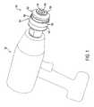
Fig. 1 is a perspective view showing a chuck in accordance with certain principles of the invention;Fig. 2 is a perspective view of an accessory formed with a shank in accordance with certain principles of the invention;Fig. 3 is a sectional view showing a locking mechanism of the chuck ofFig. 1 in a locked mode in accordance with certain principles of the invention;Fig. 4 is a side sectional view showing the locking mechanism ofFig. 3 in the locked mode in accordance with certain principles of the invention;Fig. 5 is a sectional view showing the locking mechanism ofFig. 3 in a transition mode in accordance with certain principles of the invention; andFig. 6 is a diagrammatical view showing a locking element of the locking mechanism ofFig. 3 in transition between two positions at which the locking element is in a locked position in accordance with certain principles of the invention.- Referring to
Fig. 1 , achuck 30 can be coupled to a power driver such as, for example, adrill 32, shown in phantom, for rotating the chuck. Thechuck 30 is designed with a shank-receivingopening 34 for receiving and locking abit 36, as shown inFig. 2 , having ashank 38 with a plurality of spaced, axially-alignedribs 40, separated by a plurality of axially-alignedgrooves 42. A free, or rear, end of each of theribs 40 is formed with a slanting surface 44 (Fig. 6 ), which slants forwardly from afirst side edge 46 to asecond edge 48 of the rear end of the rib. Each of theribs 40 is formed with atransaxial groove 50, where all of the grooves are located in a common plane perpendicular to the axis of thebit 36.
A plurality of bits, having ribs and grooves formed in the shanks, are disclosed inEP1128923 . The ribs of the bits disclosed in the above-noted pending patent application may be modified by the formation of a groove, such as thegroove 50, to facilitate insertion and locking of the modified bits in thechuck 30. - Referring to
Figs. 1 and4 , thechuck 30 includes achuck body 52 formed with a plurality of spacedribs 54, which extend radially inward from an inner wall of the shank-receivingopening 34, withgrooves 56 between the ribs. The chuck disclosed in the above-identified pending patent application is formed with ribs and grooves in a similar arrangement. - Referring to
Fig. 4 , thechuck body 52 includes threeslots 58, each of which is formed.radially through acylindrical wall 60 of the body adjacent an inboard end of therespective ribs 54 of the body and in acommon plane 61 perpendicular to the axis of the body. Asmall hole 62 is formed through thewall 60 of the body at a location to the rear of theplane 61 of theslots 58. - A
latching unit 64 is formed with a movable external element, such as acircular band 66, which is located about thechuck body 52 radially outward of theslots 58, and is further formed with a plurality of locking elements, such as three spacedlocking fingers 68, extending radially inward from an inside wall of the band. Each of thelocking fingers 68 is located within a respective one of theslots 58, as shown inFigs. 3, 4 and 5 , and is movable angularly in theplane 61 between opposite ends of the respective slot. Referring toFig. 4 , acoil spring 70 is located within the opening 34 of thechuck body 52, just rearward of theplane 61. Thespring 70 is formed with a straightforward end 72, which is located in a small hole in an intermediate portion of one of thelocking fingers 68, and a straightrearward end 74, which is located in the opening 62 of thechuck body 52. - As represented in the illustration of
Fig. 3 , an operator has inserted the rear portion of theshank 38 into theopening 34 of thechuck body 52, which is guided by the ribs 54 (not shown inFig. 3 ), as described in the above-noted pending patent application, to a position slightly forward of theplane 61, as represented inFig. 6 . Referring again toFig. 3 , in this position, each of thelocking fingers 68 is at one end of the respective one of theslots 58, which precludes movement of theband 66 and the fingers in a counterclockwise direction. Also, each of thelocking fingers 68 is aligned with, and to the rear of, theslanted surface 44 of a respective one of theribs 40 of theshank 38. As theshank 38 is moved further into the chuck opening 34, theslanted surface 44 of eachrib 40 engages therespective finger 68 and moves the finger, and theband 66, in a rotary direction within theplane 61, whereby thespring 70 is being wound in a tensioning direction. Eventually, thefingers 68 are moved angularly in theplane 61 to a position of alignment with a respective one of thegrooves 42 of theshank 38, as shown inFig. 5 . - Upon continued insertion movement of the
shank 38, thegrooves 42 of theshank 38 allow the continued rearward movement of the shank by providing a clear path for the shank past therespective locking fingers 68, which remain in theplane 61. However, the side walls of thegrooves 42 restrain the fingers from moving angularly within theplane 61, whereby thespring 70 remains in the tensioned condition. For illustration purposes only, the relative axial movement of thegrooves 42 of theshank 38 and thefingers 68 is represented inFig. 6 by the dashedline finger 68a, it being understood that thefinger 68a has remained in theplane 61. - As the shank 3 8 is moved further rearward, the
transaxial groove 50 of the shank is eventually aligned with theplane 61, where the lockingfingers 68 are now free of the restraints of thegrooves 42 thereon. At this time, the tensionedspring 70 relaxes to move the lockingfingers 68 in a clockwise direction to the limit of the opposite ends of therespective slots 58. Under the released energy of therelaxed spring 70, thefingers 68 are moved into respective ones of thetransaxial grooves 50 of theshank 38. For illustration purposes only, this movement of thefingers 68 is represented by the dashedline finger 68b inFig. 6 , it being understood that thefinger 68b has remained in theplane 61. - The bit 3 6 is now locked with the
chuck 30, whereby axial movement of the bit relative to thechuck body 52 is precluded as long as the lockingfingers 68 remain in thetransaxial groove 50. - When the operator desires to remove the bit 3 6 from the
chuck 30, the operator turns theband 66 by hand to move the lockingfingers 68 out of thetransaxial groove 50 and into alignment with thegrooves 42 of theshank 38. Thebit 36 can now be withdrawn from thechuck 30. - The axial width of the transaxial groove 5 0 of the
shank 38 can be slightly wider than the width of the lockingfingers 68 to provide a firm lock for use of thebit 36, for example, in a rotary drilling operation. Also, thetransaxial groove 50 of theshank 38 can be somewhat wider than the width of the lockingfingers 68 to allow some axial movement of thebit 36, for example, in a hammering or hammer drilling operation.
Claims (14)
- A power drivable chuck (30) for receiving and clamping a shank (38) having at least one axial groove (42) formed in the periphery thereof extending to a free end (40) of the shank, and having a transaxial groove (50) formed in a side wall, along an intermediate portion, of the axial groove, which comprises:a body (52) having an opening (34) therein for receipt of the shank;the opening of the body formed with a wall;at least one axial rib (54) formed on and extending inward from the wall of the opening of the body for receipt of the axial groove (42) of the shank;a locking element (68) located within the opening of thebody;wherein the locking element (68) is adapted to rotate in response to the insertion of the free end of the shank into the opening of the body, for facilitating the directing of the locking element into the axial groove of the shank to allow the shank to be moved further into the opening; and
means (70), responsive to an alignment of the locking element with the transaxial groove, for directing the locking element into the transaxial groove to lock the shank with the chuck. - A power drivable chuck according to claim 1, which further comprises:the opening and the rib each being of a prescribed size and configuration for receipt and support of the chuck-mountable shank of any one of a plurality of the shanks having different external transaxial dimensions.
- A power drivable chuck according to claim 1 or 2, which further comprises:the locking element being normally circumferentially offset from the axial rib of the body.
- A power drivable chuck according to any one of the preceding claims, which further comprises:the locking element being confined for angular movement only within a plane (61) perpendicular to an axis of the opening of the body.
- A power drivable chuck according to any one of the preceding claims, which further comprises:a stop surface formed on the body;the locking element being biasingly and normally urged into engagement with the stop surface to locate the locking element for initiation of movement of the locking element upon insertion of the shank into the opening of the body.
- A power drivable chuck according to any one of the preceding claims, wherein the means for facilitating comprises:the locking element formed with a surface located for engagement with the free end of the shank upon insertion thereof into the opening of the body;the locking element being mounted within the body for rotary movement; anda biasing member (70) in engagement with the locking member for continuously urging the locking member in a prescribed direction.
- A power drivable chuck according to any one of the preceding claims, wherein the means for directing comprises:the locking element being mounted within the body for rotary movement; anda biasing member (70) in engagement with the locking element for normally urging the locking member in a prescribed direction.
- A power drivable chuck as set forth in claim 1, which further comprises:a slot (58) formed through the body;a movable external element (66) located outside the body adjacent the slot formed therethrough;the locking element being formed on the movable external element and extending inward therefrom and through the slot formed in the body.
- A power drivable chuck according to any one of the preceding claims, which further comprises:a slot (58) formed through the body;the locking element being located within the slot for movement relative thereto;the slot formed with a radial length sufficient to allow the locking element to be moved between a locked position and an unlocked position.
- A power drivable chuck according to claim 8 or 9, wherein:the slot has a first end surface at first end thereof and a second end surface at a second end thereof spaced from the first end;
the locking element is located within the opening of the body and has a portion thereof located within the slot for movement relative thereto within a plane (61) between the first end surface and the second surface of the slot; and
the biasing member normally urges the locking element into engagement with the first end surface and allowing movement of the locking element toward the second end surface upon the application of a force sufficient to overcome an urging force as applied by the biasing member. - The power drivable chuck according to claim 10, which further comprises:the locking element is formed with a surface which is normally positioned to engage and be responsive to the free end of the shank being inserted into the opening of the body to cam the locking element a first position to a second position.
- A power drivable chuck according to claim 10 or 11, which further comprises:the slot is a first slot formed through the body in the plane which is a transaxial plane (61);at least a second slot formed in the body in the transaxial plane and spaced from the first slot;the locking element is a first locking element;at least a second locking member located within the opening of the body and having a portion thereof located within the at least second slot for movement relative thereto within the transaxial plane between the first end surface and the second surface of the slot;the biasing member normally urging the first locking element and the at least second locking element into engagement with the respective first end surfaces and allowing movement of the locking elements toward the respective second end surfaces upon the application of a force sufficient to overcome an urging force as applied by the biasing element.
- A power drivable chuck according to claim 12, which further comprises:a circular band (66) located outside of the body within the transaxial plane and movable relative to the body;the locking elements (68) being formed on the circular band at spaced locations thereof and extending inward therefrom and through the respective slots, whereby the locking elements are movable within the respective slots upon movement of the circular band.
- An accessory (36), which comprises:a shank (38) having at least one axial groove (42) formed in the periphery thereof extending to a free end (40) of the shank, and having a transaxial groove (50) formed in a side wall, along an intermediate portion, of the axial groove; andthe free end of the shank being formed with at least one slanting surface (44) which slants from a first edge (46) at a first side of the shank to a second edge (48) at a second side of the shank located generally opposite the first side of the shank.
Applications Claiming Priority (3)
| Application Number | Priority Date | Filing Date | Title |
|---|---|---|---|
| US14482799P | 1999-07-21 | 1999-07-21 | |
| US144827P | 1999-07-21 | ||
| PCT/US2000/019945WO2001007186A1 (en) | 1999-07-21 | 2000-07-21 | Power drivable chuck |
Publications (3)
| Publication Number | Publication Date |
|---|---|
| EP1220727A1 EP1220727A1 (en) | 2002-07-10 |
| EP1220727A4 EP1220727A4 (en) | 2004-12-15 |
| EP1220727B1true EP1220727B1 (en) | 2008-12-24 |
Family
ID=22510324
Family Applications (1)
| Application Number | Title | Priority Date | Filing Date |
|---|---|---|---|
| EP00948871AExpired - LifetimeEP1220727B1 (en) | 1999-07-21 | 2000-07-21 | Power drivable chuck |
Country Status (7)
| Country | Link |
|---|---|
| US (1) | US6390739B1 (en) |
| EP (1) | EP1220727B1 (en) |
| CN (2) | CN1597202A (en) |
| AT (1) | ATE418410T1 (en) |
| AU (1) | AU6230600A (en) |
| DE (1) | DE60041200D1 (en) |
| WO (1) | WO2001007186A1 (en) |
Families Citing this family (26)
| Publication number | Priority date | Publication date | Assignee | Title |
|---|---|---|---|---|
| CN1204988C (en)* | 1999-07-21 | 2005-06-08 | 布莱克-德克尔公司 | Power Drive Chuck |
| DE10058587A1 (en)* | 2000-11-25 | 2002-05-29 | Hilti Ag | Rotary machine tool, especially drill, has two sets of grooves in its insertion region for receiving male members of tool mounting |
| US20030078311A1 (en) | 2001-10-19 | 2003-04-24 | Ulrich Muller | Process for the alkoxylation of organic compounds in the presence of novel framework materials |
| DE20203129U1 (en)* | 2002-02-27 | 2002-05-08 | Quanz, Reiner, 42859 Remscheid | Rotating tool with a clamping shank |
| DE502004010872D1 (en)* | 2003-11-26 | 2010-04-22 | Hilti Ag | Tool holder for a rotating and beating tool |
| US8132990B2 (en)* | 2003-12-23 | 2012-03-13 | Lynn Everett Bauman | Bit holding apparatus for use with a power tool |
| US7354230B2 (en) | 2003-12-23 | 2008-04-08 | Lynn Bauman | Bit holding apparatus for use with a power tool |
| US7752946B2 (en)* | 2006-04-04 | 2010-07-13 | Shyh-Ming Wang | Socket for wrenches |
| US20070227311A1 (en)* | 2006-04-04 | 2007-10-04 | Shyh-Ming Wang | Socket for a wrench |
| USD579033S1 (en)* | 2007-10-25 | 2008-10-21 | Hougen Manufacturing, Inc. | Annular cutter |
| BRPI0722271A2 (en) | 2007-11-29 | 2014-04-22 | Airbus Operations Gmbh | METHOD FOR CODING A DRILLING DEVICE |
| US8622401B2 (en)* | 2009-02-27 | 2014-01-07 | Black & Decker Inc. | Bit retention device |
| US8800999B2 (en)* | 2009-02-27 | 2014-08-12 | Black & Decker Inc. | Bit retention device |
| US8381830B2 (en) | 2009-05-05 | 2013-02-26 | Black & Decker Inc. | Power tool with integrated bit retention device |
| CN201446519U (en)* | 2009-06-05 | 2010-05-05 | 南京德朔实业有限公司 | Electric tool |
| CN102059569A (en)* | 2010-10-29 | 2011-05-18 | 无锡迪奥机械有限公司 | Clamping chuck for automatic lathe |
| ES2646765T3 (en)* | 2011-08-22 | 2017-12-15 | Mst Corporation | Shrink fit toolholder |
| US10150205B2 (en) | 2012-02-15 | 2018-12-11 | Black & Decker Inc. | Fastening tools with floating magnet sleeves |
| US9227309B2 (en) | 2012-02-15 | 2016-01-05 | Black & Decker Inc. | Quick change bit holder with ring magnet |
| US9156147B2 (en) | 2012-02-15 | 2015-10-13 | Black & Decker Inc. | Quick change bit holder with ring magnet |
| US9943946B2 (en) | 2012-02-15 | 2018-04-17 | Black & Decker Inc. | Tool bits with floating magnet sleeves |
| US9505108B2 (en) | 2012-02-15 | 2016-11-29 | Black & Decker Inc. | Bit holder with floating magnet sleeve |
| USD789761S1 (en) | 2015-11-02 | 2017-06-20 | Black & Decker Inc. | Torsion bit |
| AT15846U1 (en)* | 2017-03-14 | 2018-07-15 | Ceratizit Austria Gmbh | Cutting tool for the rotational machining of a workpiece |
| EP3424645B1 (en)* | 2017-07-07 | 2021-05-05 | Von Arx AG | Coupling for the connection of a swappable tool head with a machine part of a press device |
| CN110449605B (en)* | 2019-07-03 | 2021-02-12 | 广州通发智能装备股份有限公司 | High numerical control lathe who stabilizes processing |
Family Cites Families (13)
| Publication number | Priority date | Publication date | Assignee | Title |
|---|---|---|---|---|
| US1034723A (en)* | 1911-04-01 | 1912-08-06 | Mueller Mfg Co H | Tool-retaining device for boring-bars. |
| US1138465A (en) | 1914-11-19 | 1915-05-04 | North Bros Mfg Co | Chuck. |
| US1311961A (en)* | 1918-05-31 | 1919-08-05 | Gairing Needham Tool Co Inc | Gage for floating-tool holders. |
| US1413101A (en)* | 1920-08-27 | 1922-04-18 | Samuel J Cushing | Tool holder |
| US2387339A (en)* | 1943-08-21 | 1945-10-23 | George J Meyer | Chuck |
| US2393424A (en)* | 1945-01-11 | 1946-01-22 | Howard I Selch | Boring or like tool |
| US5340245A (en) | 1990-10-16 | 1994-08-23 | Robert Bosch Gmbh | Device on portable machine tools |
| US5316323A (en)* | 1993-01-08 | 1994-05-31 | Victor Jovanovic | Two-part tool holding fixture |
| US5398946A (en)* | 1993-12-29 | 1995-03-21 | Poly-Tech Industries | Chuck having one-step lock and release |
| FR2748304B1 (en)* | 1996-05-02 | 1998-06-26 | Lemforder Nacam Sa | DEVICE FOR COUPLING TWO SHAFTS |
| US6053675A (en)* | 1998-06-26 | 2000-04-25 | Black & Decker Inc. | Quick-acting tool bit holder |
| US6053765A (en)* | 1998-10-16 | 2000-04-25 | Lear Automotive Dearborn, Inc. | Electrical connector incorporating a light |
| DE69938838D1 (en)* | 1998-11-12 | 2008-07-10 | Black & Decker Inc | FEED, DRILL, ASSEMBLY AND ASSEMBLY METHOD |
- 2000
- 2000-07-21USUS09/621,083patent/US6390739B1/ennot_activeExpired - Fee Related
- 2000-07-21EPEP00948871Apatent/EP1220727B1/ennot_activeExpired - Lifetime
- 2000-07-21WOPCT/US2000/019945patent/WO2001007186A1/enactiveApplication Filing
- 2000-07-21DEDE60041200Tpatent/DE60041200D1/ennot_activeExpired - Fee Related
- 2000-07-21ATAT00948871Tpatent/ATE418410T1/ennot_activeIP Right Cessation
- 2000-07-21CNCN200410085623.XApatent/CN1597202A/enactivePending
- 2000-07-21AUAU62306/00Apatent/AU6230600A/ennot_activeAbandoned
- 2000-07-21CNCN00813137.6Apatent/CN1250365C/ennot_activeExpired - Fee Related
Also Published As
| Publication number | Publication date |
|---|---|
| WO2001007186A1 (en) | 2001-02-01 |
| CN1250365C (en) | 2006-04-12 |
| DE60041200D1 (en) | 2009-02-05 |
| AU6230600A (en) | 2001-02-13 |
| EP1220727A1 (en) | 2002-07-10 |
| EP1220727A4 (en) | 2004-12-15 |
| US6390739B1 (en) | 2002-05-21 |
| ATE418410T1 (en) | 2009-01-15 |
| CN1597202A (en) | 2005-03-23 |
| CN1374896A (en) | 2002-10-16 |
Similar Documents
| Publication | Publication Date | Title |
|---|---|---|
| EP1220727B1 (en) | Power drivable chuck | |
| US6533291B2 (en) | Chuck having quick change mechanism | |
| US6488451B1 (en) | Drive shaft lock | |
| US6517088B1 (en) | Lockable drill chuck | |
| US4184692A (en) | Motor quick-change chuck system for tool having cylindrically shaped adapter portion | |
| US4188041A (en) | Motor quick-change chuck system for tool having cylindrically shaped adapter portion | |
| US4395170A (en) | Drill, drill chuck, and methods of chucking and unchucking | |
| US4234277A (en) | Motor quick-change chuck system for tool having cylindrically shaped adapter portion | |
| US7654779B2 (en) | Power tool | |
| US6902358B2 (en) | Power drivable chuck | |
| US6092814A (en) | Tool holder for inserted tools in drilling and/or hammering machines | |
| US7431308B2 (en) | Tool-holding chuck for equipping a rotating machine, provided with sequenced radial and axial locking means | |
| US7469909B2 (en) | Chuck for receiving tools operated by rotating around the axis thereof | |
| EP1857209B1 (en) | Tool-less blade clamping apparatus for a reciprocating tool | |
| US5988957A (en) | Quick clamp | |
| EP1534453B1 (en) | Quick-connect chuck mechanism | |
| US20040146367A1 (en) | Guide mechanism for power drill | |
| JP2002011677A (en) | Tool storage device | |
| US4273344A (en) | Motor quick-change chuck system for tool having cylindrically shaped adapter portion | |
| US5129662A (en) | Chuck | |
| GB2423948A (en) | Tool holder for a hand held power tool | |
| US5464231A (en) | Chuck with jaws having curved engagement surfaces | |
| JPH07266181A (en) | Locking device for tool holder of hand-held type machine tool | |
| US6343903B1 (en) | Tool holder of hollow taper shank in tool machine | |
| EP1285711B1 (en) | Cutter holder for cutting metal-working machine |
Legal Events
| Date | Code | Title | Description |
|---|---|---|---|
| PUAI | Public reference made under article 153(3) epc to a published international application that has entered the european phase | Free format text:ORIGINAL CODE: 0009012 | |
| 17P | Request for examination filed | Effective date:20020220 | |
| AK | Designated contracting states | Kind code of ref document:A1 Designated state(s):AT BE CH CY DE DK ES FI FR GB GR IE IT LI LU MC NL PT SE | |
| AX | Request for extension of the european patent | Free format text:AL;LT;LV;MK;RO;SI | |
| A4 | Supplementary search report drawn up and despatched | Effective date:20041028 | |
| RIC1 | Information provided on ipc code assigned before grant | Ipc:7B 23B 31/113 B Ipc:7B 23B 31/103 A | |
| 17Q | First examination report despatched | Effective date:20060316 | |
| GRAP | Despatch of communication of intention to grant a patent | Free format text:ORIGINAL CODE: EPIDOSNIGR1 | |
| GRAS | Grant fee paid | Free format text:ORIGINAL CODE: EPIDOSNIGR3 | |
| GRAA | (expected) grant | Free format text:ORIGINAL CODE: 0009210 | |
| AK | Designated contracting states | Kind code of ref document:B1 Designated state(s):AT BE CH CY DE DK ES FI FR GB GR IE IT LI LU MC NL PT SE | |
| REG | Reference to a national code | Ref country code:GB Ref legal event code:FG4D | |
| REG | Reference to a national code | Ref country code:CH Ref legal event code:EP | |
| REG | Reference to a national code | Ref country code:IE Ref legal event code:FG4D | |
| REF | Corresponds to: | Ref document number:60041200 Country of ref document:DE Date of ref document:20090205 Kind code of ref document:P | |
| PG25 | Lapsed in a contracting state [announced via postgrant information from national office to epo] | Ref country code:FI Free format text:LAPSE BECAUSE OF FAILURE TO SUBMIT A TRANSLATION OF THE DESCRIPTION OR TO PAY THE FEE WITHIN THE PRESCRIBED TIME-LIMIT Effective date:20081224 Ref country code:NL Free format text:LAPSE BECAUSE OF FAILURE TO SUBMIT A TRANSLATION OF THE DESCRIPTION OR TO PAY THE FEE WITHIN THE PRESCRIBED TIME-LIMIT Effective date:20081224 | |
| NLV1 | Nl: lapsed or annulled due to failure to fulfill the requirements of art. 29p and 29m of the patents act | ||
| PG25 | Lapsed in a contracting state [announced via postgrant information from national office to epo] | Ref country code:BE Free format text:LAPSE BECAUSE OF FAILURE TO SUBMIT A TRANSLATION OF THE DESCRIPTION OR TO PAY THE FEE WITHIN THE PRESCRIBED TIME-LIMIT Effective date:20081224 Ref country code:ES Free format text:LAPSE BECAUSE OF FAILURE TO SUBMIT A TRANSLATION OF THE DESCRIPTION OR TO PAY THE FEE WITHIN THE PRESCRIBED TIME-LIMIT Effective date:20090404 | |
| PG25 | Lapsed in a contracting state [announced via postgrant information from national office to epo] | Ref country code:SE Free format text:LAPSE BECAUSE OF FAILURE TO SUBMIT A TRANSLATION OF THE DESCRIPTION OR TO PAY THE FEE WITHIN THE PRESCRIBED TIME-LIMIT Effective date:20090324 Ref country code:PT Free format text:LAPSE BECAUSE OF FAILURE TO SUBMIT A TRANSLATION OF THE DESCRIPTION OR TO PAY THE FEE WITHIN THE PRESCRIBED TIME-LIMIT Effective date:20090525 Ref country code:AT Free format text:LAPSE BECAUSE OF FAILURE TO SUBMIT A TRANSLATION OF THE DESCRIPTION OR TO PAY THE FEE WITHIN THE PRESCRIBED TIME-LIMIT Effective date:20081224 | |
| PG25 | Lapsed in a contracting state [announced via postgrant information from national office to epo] | Ref country code:DK Free format text:LAPSE BECAUSE OF FAILURE TO SUBMIT A TRANSLATION OF THE DESCRIPTION OR TO PAY THE FEE WITHIN THE PRESCRIBED TIME-LIMIT Effective date:20081224 | |
| PLBE | No opposition filed within time limit | Free format text:ORIGINAL CODE: 0009261 | |
| STAA | Information on the status of an ep patent application or granted ep patent | Free format text:STATUS: NO OPPOSITION FILED WITHIN TIME LIMIT | |
| PGFP | Annual fee paid to national office [announced via postgrant information from national office to epo] | Ref country code:GB Payment date:20090727 Year of fee payment:10 Ref country code:DE Payment date:20090729 Year of fee payment:10 | |
| 26N | No opposition filed | Effective date:20090925 | |
| PG25 | Lapsed in a contracting state [announced via postgrant information from national office to epo] | Ref country code:MC Free format text:LAPSE BECAUSE OF NON-PAYMENT OF DUE FEES Effective date:20090731 | |
| REG | Reference to a national code | Ref country code:CH Ref legal event code:PL | |
| REG | Reference to a national code | Ref country code:FR Ref legal event code:ST Effective date:20100331 | |
| REG | Reference to a national code | Ref country code:IE Ref legal event code:MM4A | |
| PG25 | Lapsed in a contracting state [announced via postgrant information from national office to epo] | Ref country code:FR Free format text:LAPSE BECAUSE OF NON-PAYMENT OF DUE FEES Effective date:20090731 Ref country code:CH Free format text:LAPSE BECAUSE OF NON-PAYMENT OF DUE FEES Effective date:20090731 Ref country code:LI Free format text:LAPSE BECAUSE OF NON-PAYMENT OF DUE FEES Effective date:20090731 | |
| PGFP | Annual fee paid to national office [announced via postgrant information from national office to epo] | Ref country code:IT Payment date:20090728 Year of fee payment:10 | |
| PG25 | Lapsed in a contracting state [announced via postgrant information from national office to epo] | Ref country code:IE Free format text:LAPSE BECAUSE OF NON-PAYMENT OF DUE FEES Effective date:20090721 | |
| PG25 | Lapsed in a contracting state [announced via postgrant information from national office to epo] | Ref country code:GR Free format text:LAPSE BECAUSE OF FAILURE TO SUBMIT A TRANSLATION OF THE DESCRIPTION OR TO PAY THE FEE WITHIN THE PRESCRIBED TIME-LIMIT Effective date:20090325 | |
| GBPC | Gb: european patent ceased through non-payment of renewal fee | Effective date:20100721 | |
| PG25 | Lapsed in a contracting state [announced via postgrant information from national office to epo] | Ref country code:DE Free format text:LAPSE BECAUSE OF NON-PAYMENT OF DUE FEES Effective date:20110201 Ref country code:LU Free format text:LAPSE BECAUSE OF NON-PAYMENT OF DUE FEES Effective date:20090721 | |
| REG | Reference to a national code | Ref country code:DE Ref legal event code:R119 Ref document number:60041200 Country of ref document:DE Effective date:20110201 | |
| PG25 | Lapsed in a contracting state [announced via postgrant information from national office to epo] | Ref country code:IT Free format text:LAPSE BECAUSE OF NON-PAYMENT OF DUE FEES Effective date:20100721 | |
| PG25 | Lapsed in a contracting state [announced via postgrant information from national office to epo] | Ref country code:GB Free format text:LAPSE BECAUSE OF NON-PAYMENT OF DUE FEES Effective date:20100721 | |
| PG25 | Lapsed in a contracting state [announced via postgrant information from national office to epo] | Ref country code:CY Free format text:LAPSE BECAUSE OF FAILURE TO SUBMIT A TRANSLATION OF THE DESCRIPTION OR TO PAY THE FEE WITHIN THE PRESCRIBED TIME-LIMIT Effective date:20081224 |