EP1219217A1 - Coffee machine - Google Patents
Coffee machineDownload PDFInfo
- Publication number
- EP1219217A1 EP1219217A1EP01114849AEP01114849AEP1219217A1EP 1219217 A1EP1219217 A1EP 1219217A1EP 01114849 AEP01114849 AEP 01114849AEP 01114849 AEP01114849 AEP 01114849AEP 1219217 A1EP1219217 A1EP 1219217A1
- Authority
- EP
- European Patent Office
- Prior art keywords
- dispenser cup
- cup
- machine
- sprinkler
- axis
- Prior art date
- Legal status (The legal status is an assumption and is not a legal conclusion. Google has not performed a legal analysis and makes no representation as to the accuracy of the status listed.)
- Granted
Links
- XLYOFNOQVPJJNP-UHFFFAOYSA-NwaterSubstancesOXLYOFNOQVPJJNP-UHFFFAOYSA-N0.000claimsabstractdescription30
- 238000001802infusionMethods0.000claimsabstractdescription21
- 239000002775capsuleSubstances0.000claimsdescription24
- 238000007789sealingMethods0.000claimsdescription12
- 101100441413Caenorhabditis elegans cup-15 geneProteins0.000description29
- 230000000284resting effectEffects0.000description4
- 239000012815thermoplastic materialSubstances0.000description2
- 238000010586diagramMethods0.000description1
- 230000005484gravityEffects0.000description1
- 239000007788liquidSubstances0.000description1
- 238000005325percolationMethods0.000description1
- 230000000717retained effectEffects0.000description1
- 238000011144upstream manufacturingMethods0.000description1
Images


Classifications
- A—HUMAN NECESSITIES
- A47—FURNITURE; DOMESTIC ARTICLES OR APPLIANCES; COFFEE MILLS; SPICE MILLS; SUCTION CLEANERS IN GENERAL
- A47J—KITCHEN EQUIPMENT; COFFEE MILLS; SPICE MILLS; APPARATUS FOR MAKING BEVERAGES
- A47J31/00—Apparatus for making beverages
- A47J31/24—Coffee-making apparatus in which hot water is passed through the filter under pressure, i.e. in which the coffee grounds are extracted under pressure
- A47J31/34—Coffee-making apparatus in which hot water is passed through the filter under pressure, i.e. in which the coffee grounds are extracted under pressure with hot water under liquid pressure
- A47J31/36—Coffee-making apparatus in which hot water is passed through the filter under pressure, i.e. in which the coffee grounds are extracted under pressure with hot water under liquid pressure with mechanical pressure-producing means
- A47J31/3604—Coffee-making apparatus in which hot water is passed through the filter under pressure, i.e. in which the coffee grounds are extracted under pressure with hot water under liquid pressure with mechanical pressure-producing means with a mechanism arranged to move the brewing chamber between loading, infusing and ejecting stations
- A47J31/3623—Cartridges being employed
- A47J31/3638—Means to eject the cartridge after brewing
- A—HUMAN NECESSITIES
- A47—FURNITURE; DOMESTIC ARTICLES OR APPLIANCES; COFFEE MILLS; SPICE MILLS; SUCTION CLEANERS IN GENERAL
- A47J—KITCHEN EQUIPMENT; COFFEE MILLS; SPICE MILLS; APPARATUS FOR MAKING BEVERAGES
- A47J31/00—Apparatus for making beverages
- A47J31/24—Coffee-making apparatus in which hot water is passed through the filter under pressure, i.e. in which the coffee grounds are extracted under pressure
- A47J31/34—Coffee-making apparatus in which hot water is passed through the filter under pressure, i.e. in which the coffee grounds are extracted under pressure with hot water under liquid pressure
- A47J31/36—Coffee-making apparatus in which hot water is passed through the filter under pressure, i.e. in which the coffee grounds are extracted under pressure with hot water under liquid pressure with mechanical pressure-producing means
- A47J31/3604—Coffee-making apparatus in which hot water is passed through the filter under pressure, i.e. in which the coffee grounds are extracted under pressure with hot water under liquid pressure with mechanical pressure-producing means with a mechanism arranged to move the brewing chamber between loading, infusing and ejecting stations
- A47J31/3623—Cartridges being employed
- A47J31/3633—Means to perform transfer from a loading position to an infusing position
Definitions
- the present inventionrelates to a coffee machine.
- the present inventionrelates to a coffee machine of the type comprising a horizontal dispenser assembly, in turn comprising a boiler with a pressurized-hot-water sprinkler; a dispenser cup for housing at least part of a ground-coffee container and positioned facing the sprinkler; a hydraulic thrust cylinder aligned with the boiler along a horizontal axis, located on the opposite side of the dispenser cup to the boiler, and comprising a piston for moving the dispenser cup to and from an infusion position in which the dispenser cup is connected to the sprinkler; and a vertical loading conduit for loading a ground-coffee container between the sprinkler and the dispenser cup.
- the dispenser cupis fixed with respect to the hydraulic cylinder piston, is aligned with the boiler sprinkler and the hydraulic cylinder along said horizontal axis, and is movable by the piston between said infusion position and a withdrawn rest or loading position in which the dispenser cup defines, with the sprinkler, a passage located directly beneath the loading conduit and for receiving a ground-coffee container positioned on edge and coaxial with said horizontal axis.
- a ground-coffee containeris fed on edge along the loading conduit into said passage where it is arrested by a shutter plate, which arrests the fall of the container and keeps it in said position aligned with the dispenser cup and the boiler sprinkler.
- the hydraulic cylinderis then activated to move the dispenser cup into the infusion position in which the dispenser cup normally houses at least part of the container and presses it in fluidtight manner against the sprinkler. Once the coffee is percolated, the dispenser cup is restored to the rest position and the shutter plate is removed to allow the used container to drop through the passage.
- the known machine described abovehas several drawbacks, the worst of which all depend, directly or indirectly, on the presence of the shutter plate. That is, owing to the presence of the shutter plate, the known machine described above, as opposed to using any type of ground-coffee container, be it a wafer or rigid capsule, can only operate using special containers having a rigid, perfectly cylindrical lateral wall capable of ensuring, in contact with the shutter plate, that the container is perfectly coaxial with the sprinkler and dispenser cup. Moreover, the shutter plate must be capable of performing movements independent of those imparted to the dispenser cup by the hydraulic cylinder, and must therefore have an independent actuating device normally comprising an electric motor featuring a given number of control microswitches and in itself bulky and expensive.
- a coffee machine of the typecomprising a horizontal dispenser assembly, in turn comprising a boiler with a pressurized-hot-water sprinkler; a dispenser cup for housing at least part of a ground-coffee container, the dispenser cup being positioned facing said sprinkler; a hydraulic thrust cylinder aligned with the boiler along a horizontal first axis and located on the opposite side of said dispenser cup to the boiler, the hydraulic cylinder comprising a piston for moving the dispenser cup to and from an infusion position in which the dispenser cup is connected to said sprinkler; and a vertical loading conduit for loading a said container between said sprinkler and said dispenser cup; the machine being characterized in that said dispenser cup is supported by said piston to oscillate - with respect to the piston, preferably by virtue of a thrust imparted by the piston, and about a second axis, preferably a horizontal axis, crosswise to said first axis - between a load setting in which the dispenser cup faces at least partly upwards and towards said loading conduit, and an
- Number 1 in Figure 1indicates as a whole a coffee machine comprising a cold-water tank 2, an outlet conduit 3 of which is fitted with an electromagnetic pump 4.
- Conduit 3connects tank 2 to an inlet 5 of a boiler 6, an outlet 7 of which supplies pressurized hot water along a conduit 8 to an inlet of a slide valve 9.
- Valve 9when moved rightwards in Figure 1, connects conduit 8 to a hot-water nozzle 10, and, when moved leftwards in Figure 1, connects conduit 8 to a conduit 11 for supplying pressurized hot water to a coffee dispenser assembly 12, which comprises boiler 6, and a hydraulic cylinder 13 coaxial with and facing boiler 6 and in turn comprising a piston 14 movable to and from boiler 6 to move a coffee dispenser cup 15 to and from a position engaging a sprinkler 16 projecting axially from boiler 6 and for dispensing pressurized hot water. More specifically, by means of a conduit 17 through boiler 6, conduit 11 communicates directly with sprinkler 16, which is controlled by a valve 18 which only opens when the pressure inside conduit 11 reaches a given value. Conduit 11 also communicates directly with a conduit 19 for supplying pressurized water to hydraulic cylinder 13.
- valve 9When set to the middle position shown in Figure 1, valve 9 connects both pump 4 and conduit 11 to a conduit 20 for feeding water back to tank 2.
- valve 9when valve 9 is moved left- or rightwards from the middle position shown in Figure 1, pump 4 is activated so that cold water is fed to inlet 5 of boiler 6, and pressurized hot water is fed along conduit 8 to the inlet of valve 9.
- valve 9When valve 9 is moved rightwards, pressurized hot water is fed directly to nozzle 10; and, when valve 9 is moved leftwards, pressurized hot water is fed along conduit 11 to both conduits 17 and 19.
- the pressurized hot wateris prevented temporarily by valve 18 from issuing from sprinkler 16, while the pressurized hot water fed to hydraulic cylinder 13 moves piston 14 and dispenser cup 15 towards sprinkler 16.
- piston 14Upon dispenser cup 15 contacting sprinkler 16 in fluidtight manner, piston 14 is arrested and the pressure inside conduits 17 and 19 is simultaneously increased, thus opening valve 18 to percolate the coffee.
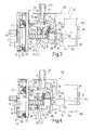
- boiler 6 in dispenser assembly 12is defined by three superimposed plates 21, 22 and 23, the intermediate plate 22 of which is embedded with an electric resistor 24 having two outer terminals 25 (Figure 2), and comprises, on the surface facing the outer plate 21, a groove closed in fluidtight manner by plate 21 and defining a coil 26 connecting inlet 5 to outlet 7.
- a cylindrical body 27, defining sprinkler 16projects axially from the surface of plate 23 facing cylinder 13, and comprises, on its own end surface facing cylinder 13, a cavity 28 for housing a respective half of a ground-coffee wafer 29, the outer casing of which is defined, as shown in Figure 6, by two paper half-wafers integral with each other along an equatorial flange 30.
- An axial hole 31is formed through plates 21, 22, 23 and cylindrical body 27, and is fitted inside, coaxially with a horizontal axis 32 of boiler 6, with a conduit 33, one end of which projects outwards of plate 21 with a fitting 34 for connecting conduit 33 and conduit 17, and the other end of which, facing hydraulic cylinder 13, is controlled by valve 18, which comprises a shutter 35 pushed towards conduit 33 by a spring 36.
- valve 18,which comprises a shutter 35 pushed towards conduit 33 by a spring 36.
- the end of hole 31 coming out inside the bottom of cavity 28is engaged in sliding manner by a tubular, goblet-shaped extractor 37, which is maintained by spring 36 in a normally extracted position inside cavity 28.
- hydraulic cylinder 13comprises a cup-shaped body 38 having a substantially cylindrical lateral wall 39 coaxial with axis 32 and closed, at the opposite end to that facing boiler 6, by an end wall 40 having an axial through hole 41 for connection to conduit 19.
- Lateral wall 39is engaged in axially-sliding and fluidtight manner by piston 14, which is substantially cylindrical and comprises, on the side facing boiler 6, a cavity 42 having a central truncated-cone-shaped projection 43 coaxial with axis 32.
- boiler 6 and cup-shaped body 38are made integral with each other by an outer bracket 44 comprising two cylindrical rods 45 lying on a substantially horizontal plane on opposite sides of boiler 6 and hydraulic cylinder 13, and extending parallel to axis 32 outside lateral wall 39.
- Bracket 44also comprises a plate 46 resting on the outer surface of end wall 40 and integral with one end of each of rods 45, the other end of each of which is integral with plate 23.
- Rods 45form part of a device 47 for axially guiding and angularly locking piston 14 with respect to cup-shaped body 38.
- Device 47comprises a ring nut 48, which is fixed, outside lateral wall 39, to the end of piston 14 facing boiler 6, and projects radially outwards with respect to lateral wall 39 with two lugs 49 supporting two bushes 50, each of which is engaged in sliding manner by a respective rod 45, and is slid by piston 14 along respective rod 45 towards boiler 6 and in opposition to a respective return spring 51 coaxial with respective rod 45 and compressed between respective bush 50 and plate 23.
- dispenser cup 15comprises a substantially cylindrical body 52 interposed between piston 14 and sprinkler 16 of boiler 6, and having, on the side facing sprinkler 16, a cavity 53 partly engaged by a perforated cup 54, the shape of which is a specular image of cavity 28.
- Cup 54is designed to receive a respective half of a wafer 29, and defines, inside cavity 53, a chamber 55 separated from the outside by cup 54 and communicating with a coffee spout 56.
- a leaf-spring extractor 57is anchored to the surface of cup 54 facing boiler 6.
- body 52is fitted with two diametrically-opposite outer pins 58 projecting outwards from body 52 and coaxial with each other and with a substantially horizontal axis 59 perpendicular to axis 32.
- the two pins 58are connected in rotary manner to respective arms of a fork 60 integral with the end of piston 14 facing boiler 6, so as to allow dispenser cup 15 to oscillate, with respect to piston 14, about axis 59 by means of and in opposition to two coil springs 61 coaxial with respective pins 58 and interposed between body 52 and fork 60.
- a leaf spring 62projects from the bottom surface of body 52 facing piston 14, and is normally maintained by springs 61 contacting projection 43 to keep body 52 in a normal receiving or load setting in which an axis 63 of body 52 slopes upwards towards boiler 6, and the inside of cup 54 is accessible from the top by a wafer 29 fed into the gap between body 52 and the free end of cylinder 27 along a vertical drop-down conduit 64 supported, over body 52, by a bracket 65 secured in a fixed position to rods 45 by means of respective bushes 66.
- dispenser assembly 12comprises a retaining device 67 in turn comprising a rod 68, a first end of which is hinged to a bracket 69, fitted to plate 23 alongside sprinkler 16 and over axis 32, so as to rotate upwards about an axis 70 parallel to axis 59 and in opposition to a spring 71, and a second end of which is shaped in the form of a hook 72 having a downward-facing, concave surface 73 which is engaged by a pin 74 parallel to pins 58 and projecting from body 52 over axis 59.
- the length of rod 68is such that the distance between hook 72 and an annular free-end surface 75 of cylindrical body 27 of sprinkler 16 is greater than the distance between pin 74 and an annular free-end surface 76 of body 52 facing boiler 6, and is less than the distance between pin 74 and surface 75 when body 52 is in the normal load setting shown in Figure 6.
- dispenser assembly 12Operation of dispenser assembly 12 will now be described with reference to Figures 3 to 6, and as of the instant ( Figures 3 and 6) in which a wafer 29 is inserted downwards into conduit 64 and dropped on edge towards dispenser cup 15.
- dispenser cup 15When this occurs, piston 14 maintains dispenser cup 15 in a normal withdrawn rest position, in which dispenser cup 15 is maintained by springs 61 in the load setting with leaf spring 62 resting on projection 43, and axis 63 sloping upwards towards boiler 6. With dispenser cup 15 in the above load setting, cup 54 is accessible from the outside to receive and retain the respective half of the wafer 29 dropped from above along conduit 64.
- piston 14is moved along axis 32 towards boiler 6 so as to also move dispenser cup 15 along axis 32 until a portion of annular surface 76 of body 52 beneath axis 32 comes into contact with a corresponding portion of annular surface 75 of sprinkler 16.
- the axial thrust of piston 14 and the resistance of sprinkler 16combine to generate a straightening moment, which rotates dispenser cup 15 about axis 59 into the infusion setting ( Figure 4) wherein axis 63 of dispenser cup 15 coincides with axis 32 of boiler 6, and surfaces 75 and 76 grip flange 30 of wafer 29 in fluidtight manner.
- Dispenser cup 15is maintained in the infusion position and setting for a given length of time, during which, pressurized hot water is fed, as already explained, through wafer 29 to produce the coffee which flows out along percolation spout 56.
- dispenser cup 15is detached from sprinkler 16 and axis 63 begins rotating upwards; in the course of which movement, wafer 29 is detached from sprinkler 16 by the thrust imparted by extractor 37, and also from cup 54 by the thrust imparted by extractor 57, but is retained by force of gravity inside cup 54.
- dispenser assembly 12is highly straightforward and practical, the only active member being hydraulic cylinder 13, and can operate with any type of wafer 29, by having no intermediate intercepting member, so that wafer 29 is fed directly into dispenser cup 15.
- dispenser assembly 12to any type of currently marketed ground-coffee container.
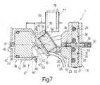
- Figure 7shows a dispenser assembly 12 substantially identical with that in Figures 2 to 6, except that wafer conduit 64 is replaced with a conduit 77 for rigid ground-coffee capsules 78, cavity 28 and extractor 37 of sprinkler 16 are dispensed with, surface 75 is a flat surface, and body 52, as opposed to cavity 53 and cup 54 with extractor 57, comprises a cavity 79 for receiving a capsule 78.
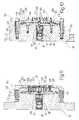
- Figure 8shows a dispenser assembly 80 similar to dispenser assembly 12 but for receiving a sealed ground-coffee capsule 81.
- sealed capsule 81of known type, comprises a cup-shaped body 82 of thermoplastic material containing a measure of ground coffee and having a relatively thin, continuous bottom wall 83, and a continuous, truncated-cone-shaped lateral wall 84 tapering towards bottom wall 83 and having an outer annular flange 85 on the opposite end to that connected to bottom wall 83.
- Sealed capsule 81is complete with a sealing film 86 connected in fluidtight manner to flange 85 to seal the respective measure of ground coffee inside cup-shaped body 82.
- Dispenser cup 15is in the form of a cup open on the side facing sprinkler 16, and comprises a truncated-cone-shaped lateral wall 87, which is closed, on the side facing hydraulic cylinder 13, by a concave bottom wall 88 through which spout 56 is formed, and is defined, on the side facing sprinkler 16, by an annular edge 89 surrounding an annular seat 90.
- Dispenser cup 15is designed to house a sealed capsule 81 with lateral wall 84 contacting the inner surface of lateral wall 87, and with flange 85 engaged inside annular seat 90.
- respective bottom wall 83is located a given distance from the concave inner surface of bottom wall 88, and defines, with bottom wall 88, a chamber 91 communicating with spout 56 and housing a known piercing device 92 operating as described later on.
- Piercing device 92comprises a number of needles 93, each of which projects axially from the inner surface of bottom wall 88, has a lateral groove 94, and has a pointed end located, in use and at rest, a relatively small distance from the outer surface of bottom wall 83 of capsule 81 inside dispenser cup 15.
- Sprinkler 16comprises, on the side facing boiler 6, a cylindrical cavity 95 coaxial with axis 32 of conduit 33, and, on the side facing dispenser cup 15, a cylindrical, internally threaded cavity 96, which is coaxial with axis 32 and connected to cavity 95 by a through hole smaller in diameter than cavities 95 and 96 and fitted with a tubular, low-friction liner 97.
- Cavities 95 and 96 and liner 97are fitted inside with a piercing device 98 comprising a hydraulic cylinder 99, an outer body of which comprises liner 97, a circular plate 100 fitted in fluidtight manner inside cavity 95 and having a central through hole 101 coaxial with axis 32, and a cup-shaped body 102 fitted inside cavity 96 with its own concavity facing boiler 6, and comprising an externally threaded lateral wall 103 engaging the internal thread of cavity 96, and a bottom wall 104 having a number of through holes 105.
- Hydraulic cylinder 99also comprises a piston 106 mounted to slide inside cup-shaped body 102 and having a rod 107 sliding in fluidtight manner inside liner 97.
- Piston 106is defined by two plates 108, 109 defining in between a chamber 110; plate 108 is integral with rod 107; and plate 109 is fitted, on the side facing bottom wall 104, with needles 111, each of which is hollow, is coaxial with a respective hole 105, and communicates with chamber 110 via a respective hole 112 formed through plate 109.
- Chamber 110communicates with hole 101 via an axial hole 113 formed along rod 107 and closed, not in fluidtight manner and on the side facing chamber 110, by a threaded cap 114, in which is formed, on the side facing plate 109, a seat for supporting a spring 115, which frictionally engages a through hole in plate 109 and is compressed between cap 114 and bottom wall 104.
- Hole 113houses valve 18, the shutter 35 of which is mounted to slide along hole 113 in opposition to relative spring 36 compressed between cap 114 and shutter 35 to keep shutter 35, at rest, contacting a seat formed at the end of hole 113 facing boiler 6.
- Cup-shaped body 102, piston 106 and needles 111are so sized that, when rod 107, at rest, is maintained contacting plate 100 by spring 115, piercing device 98 is set to a withdrawn position in which the free end of each needle 111 engages respective hole 105 but does not project from plate 109. Conversely, when piston 106 is moved, in opposition to spring 115, into contact with bottom wall 104, piercing device 98 is set to an extracted position in which part of the length of each needle 111 projects outwards of cup-shaped body 102 through respective hole 105.
- Fluidtight contact of sealed capsule 81 and sprinkler 16arrests piston 14 and simultaneously increases the pressure in conduits 17 and 19.
- the increase in pressuremoves piston 106 towards bottom wall 104, in opposition to spring 115, so as to extract needles 111 from respective holes 105 and pierce sealing film 86 of sealed capsule 81.
- valve 18When piston 106 is arrested against bottom wall 104, the pressure inside conduits 17 and 19 increases further and finally opens valve 18, so that hot water is fed into sealed capsule 81 through valve 18, cap 114, chamber 110, holes 112 and needles 111.
- the pressurized hot water fed into sealed capsule 81 -which, as stated, is made of thermoplastic material - deforms bottom wall 83, which curves outwards into chamber 91 and into contact with the tips of needles 93, which pierce it to connect the inside of sealed capsule 81 to spout 56 and so allow the liquid coffee to flow through the lateral grooves 94 in needles 93 into spout 56.
- the Figure 9 and 10 variationrelates to a further piercing device 116 for piercing sealed capsules 81 and fitted to sprinkler 16 in place of piercing device 98.
- sprinkler 16When piecing device 116 is used, sprinkler 16 simply has an axial through hole 117, which, like hole 113 in Figure 8, communicates on one side with hole 33 (not shown in Figures 9 and 10), and comes out on the other side inside a cylindrical axial cavity 118 coaxial with axis 32 and facing dispenser cup 15.
- Hole 117is controlled by valve 18, which, as in piercing device 98, comprises shutter 35 and spring 36 compressed between shutter 35 and cap 114 closing hole 117.
- An axial hole 119is formed through cap 114 to connect cavity 118 to hole 117 downstream from shutter 35.
- Cavity 118is surrounded by an annular groove formed in a flat annular end surface 120 of sprinkler 16 and housing an annular sealing member 121, which projects frontwards of annular surface 120 and surrounds a plate 122 fixed inside cavity 118 and having a central through hole 123 communicating with hole 119 and coaxial with axis 32.
- Plate 122forms part of piercing device 116 and comprises, on the side facing dispenser cup 15, a number of needles 124 integral with plate 122 and extending from plate 122 towards dispenser cup 15 in a direction parallel to axis 32.
- piercing device 116also comprises a cup-shaped body 125 coaxial with axis 32, positioned with its concavity facing cavity 118, and connected in axially-sliding manner to sprinkler 16.
- Cup-shaped body 125comprises a cylindrical lateral wall 126, an inner surface of which mates in sliding manner with a cylindrical outer surface 127 of sprinkler 16; and a bottom wall 128 facing and parallel to annular surface 120 and having a number of holes 129 coaxial with respective needles 124, and a central hole 130 coaxial with axis 32.
- Cup-shaped body 125is movable axially - in opposition to a number of axial springs 131 compressed between sprinkler 16 and lateral wall 126, and along a number of pins 132 projecting axially from sprinkler 16 and engaged in sliding manner through respective axial holes 133 formed in the thickness of lateral wall 126 - between a rest position ( Figure 9) defined by stop members defined by respective heads 134 of pins 132, and in which needles 124 are housed entirely inside cup-shaped body 125, and a work position ( Figure 10) in which bottom wall 128 contacts sealing member 121, and needles 124 project beyond an outer surface 135 of bottom wall 128 through respective holes 129.
Landscapes
- Engineering & Computer Science (AREA)
- Mechanical Engineering (AREA)
- Food Science & Technology (AREA)
- Apparatus For Making Beverages (AREA)
- Tea And Coffee (AREA)
Abstract

Description
- The present invention relates to a coffee machine.
- More specifically, the present invention relates toa coffee machine of the type comprising a horizontaldispenser assembly, in turn comprising a boiler with apressurized-hot-water sprinkler; a dispenser cup forhousing at least part of a ground-coffee container andpositioned facing the sprinkler; a hydraulic thrustcylinder aligned with the boiler along a horizontal axis,located on the opposite side of the dispenser cup to theboiler, and comprising a piston for moving the dispensercup to and from an infusion position in which thedispenser cup is connected to the sprinkler; and avertical loading conduit for loading a ground-coffeecontainer between the sprinkler and the dispenser cup.
- In a known coffee machine of the above type, thedispenser cup is fixed with respect to the hydrauliccylinder piston, is aligned with the boiler sprinkler andthe hydraulic cylinder along said horizontal axis, and ismovable by the piston between said infusion position anda withdrawn rest or loading position in which the dispenser cup defines, with the sprinkler, a passagelocated directly beneath the loading conduit and forreceiving a ground-coffee container positioned on edgeand coaxial with said horizontal axis.
- In actual use, a ground-coffee container is fed onedge along the loading conduit into said passage where itis arrested by a shutter plate, which arrests the fall ofthe container and keeps it in said position aligned withthe dispenser cup and the boiler sprinkler. The hydrauliccylinder is then activated to move the dispenser cup intothe infusion position in which the dispenser cup normallyhouses at least part of the container and presses it influidtight manner against the sprinkler. Once the coffeeis percolated, the dispenser cup is restored to the restposition and the shutter plate is removed to allow theused container to drop through the passage.
- The known machine described above has severaldrawbacks, the worst of which all depend, directly orindirectly, on the presence of the shutter plate. Thatis, owing to the presence of the shutter plate, the knownmachine described above, as opposed to using any type ofground-coffee container, be it a wafer or rigid capsule,can only operate using special containers having a rigid,perfectly cylindrical lateral wall capable of ensuring,in contact with the shutter plate, that the container isperfectly coaxial with the sprinkler and dispenser cup.Moreover, the shutter plate must be capable of performingmovements independent of those imparted to the dispenser cup by the hydraulic cylinder, and must therefore have anindependent actuating device normally comprising anelectric motor featuring a given number of controlmicroswitches and in itself bulky and expensive.
- It is an object of the present invention to providea coffee machine which is cheap and easy to produce andat the same time provides for eliminating theaforementioned drawbacks.
- According to the present invention, there isprovided a coffee machine of the type comprising ahorizontal dispenser assembly, in turn comprising aboiler with a pressurized-hot-water sprinkler; adispenser cup for housing at least part of a ground-coffeecontainer, the dispenser cup being positionedfacing said sprinkler; a hydraulic thrust cylinderaligned with the boiler along a horizontal first axis andlocated on the opposite side of said dispenser cup to theboiler, the hydraulic cylinder comprising a piston formoving the dispenser cup to and from an infusion positionin which the dispenser cup is connected to saidsprinkler; and a vertical loading conduit for loading asaid container between said sprinkler and said dispensercup; the machine being characterized in that saiddispenser cup is supported by said piston to oscillate -with respect to the piston, preferably by virtue of athrust imparted by the piston, and about a second axis,preferably a horizontal axis, crosswise to said firstaxis - between a load setting in which the dispenser cup faces at least partly upwards and towards said loadingconduit, and an unload setting in which the dispenser cupis oriented at least partly downwards, and via aninfusion setting assumed by the dispenser cup in saidinfusion position, and in which the dispenser cup iscoaxial with said first axis.
- A number of non-limiting embodiments of the presentinvention will be described by way of example withreference to the accompanying drawings, in which:
- Figure 1 shows a schematic block diagram of apreferred embodiment of the coffee machine according tothe present invention;
- Figure 2 shows a larger-scale view in perspective ofa detail in Figure 1;
- Figures 3, 4 and 5 show side views of the Figure 2detail in three different operating positions;
- Figure 6 shows an axial section of Figure 3;
- Figure 7 shows an axial section of a variation ofthe Figure 2-6 detail in the Figure 3 operating position;
- Figure 8 shows a schematic axial section of avariation of a detail in Figure 7;
- Figure 9 shows an axial section of a variation of adetail in Figure 8 in a distinct operating position;
- Figure 10 shows a section along line X-X in Figure 9of a detail in Figure 9 in a different operatingposition.
Number 1 in Figure 1 indicates as a whole a coffeemachine comprising a cold-water tank 2, anoutlet conduit 3 of which is fitted with anelectromagnetic pump 4.Conduit 3 connectstank 2 to aninlet 5 of aboiler 6, anoutlet 7 of which supplies pressurized hot water along aconduit 8 to an inlet of a slide valve 9.- Valve 9, when moved rightwards in Figure 1, connects
conduit 8 to a hot-water nozzle 10, and, when movedleftwards in Figure 1, connectsconduit 8 to aconduit 11for supplying pressurized hot water to acoffee dispenserassembly 12, which comprisesboiler 6, and ahydrauliccylinder 13 coaxial with and facingboiler 6 and in turncomprising apiston 14 movable to and fromboiler 6 tomove acoffee dispenser cup 15 to and from a positionengaging asprinkler 16 projecting axially fromboiler 6and for dispensing pressurized hot water. Morespecifically, by means of aconduit 17 throughboiler 6,conduit 11 communicates directly withsprinkler 16, whichis controlled by avalve 18 which only opens when thepressure insideconduit 11 reaches a given value.Conduit 11 also communicates directly with aconduit 19 forsupplying pressurized water tohydraulic cylinder 13. - When set to the middle position shown in Figure 1,valve 9 connects both
pump 4 andconduit 11 to aconduit 20 for feeding water back totank 2. - In actual use, when valve 9 is moved left- orrightwards from the middle position shown in Figure 1,
pump 4 is activated so that cold water is fed to inlet 5ofboiler 6, and pressurized hot water is fed alongconduit 8 to the inlet of valve 9. - When valve 9 is moved rightwards, pressurized hotwater is fed directly to
nozzle 10; and, when valve 9 ismoved leftwards, pressurized hot water is fed alongconduit 11 to bothconduits valve 18 fromissuing fromsprinkler 16, while the pressurized hotwater fed tohydraulic cylinder 13 movespiston 14 anddispenser cup 15 towardssprinkler 16. Upondispenser cup 15 contactingsprinkler 16 in fluidtight manner,piston 14 is arrested and the pressure insideconduits valve 18 topercolate the coffee. - As shown in Figure 6,
boiler 6 indispenser assembly 12 is defined by threesuperimposed plates intermediate plate 22 of which is embedded with anelectric resistor 24 having two outer terminals 25(Figure 2), and comprises, on the surface facing theouter plate 21, a groove closed in fluidtight manner byplate 21 and defining acoil 26 connectinginlet 5 tooutlet 7. Acylindrical body 27, definingsprinkler 16,projects axially from the surface ofplate 23 facingcylinder 13, and comprises, on its own endsurface facingcylinder 13, acavity 28 for housing a respective half ofa ground-coffee wafer 29, the outer casing of which isdefined, as shown in Figure 6, by two paper half-wafersintegral with each other along anequatorial flange 30. - An
axial hole 31 is formed throughplates cylindrical body 27, and is fitted inside, coaxially with ahorizontal axis 32 ofboiler 6, with aconduit 33,one end of which projects outwards ofplate 21 with afitting 34 for connectingconduit 33 andconduit 17, andthe other end of which, facinghydraulic cylinder 13, iscontrolled byvalve 18, which comprises ashutter 35pushed towardsconduit 33 by aspring 36. The end ofhole 31 coming out inside the bottom ofcavity 28 is engagedin sliding manner by a tubular, goblet-shaped extractor 37, which is maintained byspring 36 in a normallyextracted position insidecavity 28. - Still with reference to Figure 6,
hydraulic cylinder 13 comprises a cup-shaped body 38 having a substantiallycylindricallateral wall 39 coaxial withaxis 32 andclosed, at the opposite end to that facingboiler 6, byanend wall 40 having an axial throughhole 41 forconnection to conduit 19.Lateral wall 39 is engaged inaxially-sliding and fluidtight manner bypiston 14, whichis substantially cylindrical and comprises, on thesidefacing boiler 6, acavity 42 having a central truncated-cone-shapedprojection 43 coaxial withaxis 32. - As shown more clearly in Figure 2,
boiler 6 and cup-shapedbody 38 are made integral with each other by anouter bracket 44 comprising twocylindrical rods 45 lyingon a substantially horizontal plane on opposite sides ofboiler 6 andhydraulic cylinder 13, and extendingparallel toaxis 32 outsidelateral wall 39. Bracket 44also comprises aplate 46 resting on the outer surface ofend wall 40 and integral with one end of each ofrods 45, the other end of each of which is integral withplate 23. Rods 45 form part of adevice 47 for axially guidingand angularly lockingpiston 14 with respect to cup-shapedbody 38.Device 47 comprises aring nut 48, whichis fixed, outsidelateral wall 39, to the end ofpiston 14 facingboiler 6, and projects radially outwards withrespect tolateral wall 39 with twolugs 49 supportingtwobushes 50, each of which is engaged in sliding mannerby arespective rod 45, and is slid bypiston 14 alongrespective rod 45 towardsboiler 6 and in opposition to arespective return spring 51 coaxial withrespective rod 45 and compressed betweenrespective bush 50 andplate 23.- As shown more clearly in Figure 6,
dispenser cup 15comprises a substantiallycylindrical body 52 interposedbetweenpiston 14 andsprinkler 16 ofboiler 6, andhaving, on theside facing sprinkler 16, acavity 53partly engaged by a perforated cup 54, the shape of whichis a specular image ofcavity 28. Cup 54 is designed toreceive a respective half of awafer 29, and defines,insidecavity 53, achamber 55 separated from the outsideby cup 54 and communicating with acoffee spout 56. Aleaf-spring extractor 57 is anchored to the surface ofcup 54 facingboiler 6. - As shown more clearly in Figure 2,
body 52 is fittedwith two diametrically-oppositeouter pins 58 projectingoutwards frombody 52 and coaxial with each other andwith a substantiallyhorizontal axis 59 perpendicular toaxis 32. The twopins 58 are connected in rotary mannerto respective arms of afork 60 integral with the end ofpiston 14 facingboiler 6, so as to allowdispenser cup 15 to oscillate, with respect topiston 14, aboutaxis 59by means of and in opposition to twocoil springs 61coaxial withrespective pins 58 and interposed betweenbody 52 andfork 60. - As shown in Figure 6, a
leaf spring 62 projects fromthe bottom surface ofbody 52 facingpiston 14, and isnormally maintained bysprings 61 contactingprojection 43 to keepbody 52 in a normal receiving or load settingin which anaxis 63 ofbody 52 slopes upwards towardsboiler 6, and the inside of cup 54 is accessible from thetop by awafer 29 fed into the gap betweenbody 52 andthe free end ofcylinder 27 along a vertical drop-downconduit 64 supported, overbody 52, by abracket 65secured in a fixed position to rods 45 by means ofrespective bushes 66. - As shown in Figures 2 to 5,
dispenser assembly 12comprises aretaining device 67 in turn comprising arod 68, a first end of which is hinged to abracket 69,fitted toplate 23 alongsidesprinkler 16 and overaxis 32, so as to rotate upwards about anaxis 70 parallel toaxis 59 and in opposition to aspring 71, and a secondend of which is shaped in the form of ahook 72 having adownward-facing,concave surface 73 which is engaged by apin 74 parallel topins 58 and projecting frombody 52overaxis 59. The length ofrod 68 is such that the distance betweenhook 72 and an annular free-end surface 75 ofcylindrical body 27 ofsprinkler 16 is greater thanthe distance betweenpin 74 and an annular free-endsurface 76 ofbody 52 facingboiler 6, and is less thanthe distance betweenpin 74 andsurface 75 whenbody 52is in the normal load setting shown in Figure 6. - Operation of
dispenser assembly 12 will now bedescribed with reference to Figures 3 to 6, and as of theinstant (Figures 3 and 6) in which awafer 29 is inserteddownwards intoconduit 64 and dropped on edge towardsdispenser cup 15. - When this occurs,
piston 14 maintainsdispenser cup 15 in a normal withdrawn rest position, in whichdispenser cup 15 is maintained bysprings 61 in the loadsetting withleaf spring 62 resting onprojection 43, andaxis 63 sloping upwards towardsboiler 6. Withdispensercup 15 in the above load setting, cup 54 is accessiblefrom the outside to receive and retain the respectivehalf of thewafer 29 dropped from above alongconduit 64. - At this point,
piston 14 is moved alongaxis 32towardsboiler 6 so as to also movedispenser cup 15alongaxis 32 until a portion ofannular surface 76 ofbody 52 beneathaxis 32 comes into contact with acorresponding portion ofannular surface 75 ofsprinkler 16. When this occurs, the axial thrust ofpiston 14 andthe resistance ofsprinkler 16 combine to generate astraightening moment, which rotatesdispenser cup 15aboutaxis 59 into the infusion setting (Figure 4) whereinaxis 63 ofdispenser cup 15 coincides withaxis 32 ofboiler 6, andsurfaces grip flange 30 ofwafer 29 in fluidtight manner. - In the course of the above movements, given itslength and the downward thrust imparted by
spring 71,rod 68 ofretaining device 67 is maintained resting onpin 74, and, whendispenser cup 15 reaches the infusionposition and setting shown in Figure 4, is positionedwith an intermediate portion resting onpin 74. Dispenser cup 15 is maintained in the infusionposition and setting for a given length of time, duringwhich, pressurized hot water is fed, as alreadyexplained, throughwafer 29 to produce the coffee whichflows out alongpercolation spout 56.- When the pressurized hot water is cut off and
hydraulic cylinder 13 is connected to thefeedbackconduit 20 to the tank, the pressure inhydrauliccylinder 13 falls to ambient pressure, andpiston 14 ispushed back bysprings 51 into the withdrawn restposition, takingdispenser cup 15 with it. As it iswithdrawn,dispenser cup 15 is detached fromsprinkler 16andaxis 63 begins rotating upwards; in the course ofwhich movement,wafer 29 is detached fromsprinkler 16 bythe thrust imparted byextractor 37, and also from cup 54by the thrust imparted by extractor 57, but is retainedby force of gravity inside cup 54. - The above initial movement causes
pin 74 to slidealongrod 68 and engagehook 72. Since theconcave surface 73 ofhook 72 is so shaped as to only engagepin 74 and hook 72 whenpin 74 slides alongrod 68 in theopposite direction toboiler 6, further withdrawal ofpiston 14arrests pin 74 and, by virtue of the thrustexerted bysprings 51 combined withhook 72 engagingpin 74, produces a tilting moment which rotatesaxis 63downwards and movesdispenser cup 15 gradually into anunload setting (Figure 5) in which cup 54 faces at leastpartly downwards to drop the usedwafer 29 into a bin notshown. - As
dispenser cup 15 rotates downwards,pin 74 rollspartly alongconcave surface 73 ofhook 72 to eventuallyreleasehook 72, so thatdispenser cup 15 is restored bysprings 61 to the load setting (Figures 3 and 6). - As will be clear from the foregoing description,
dispenser assembly 12 is highly straightforward andpractical, the only active member beinghydrauliccylinder 13, and can operate with any type ofwafer 29,by having no intermediate intercepting member, so thatwafer 29 is fed directly intodispenser cup 15. - As will also be clear from the foregoingdescription, very few changes need be made to adapt
dispenser assembly 12 to any type of currently marketedground-coffee container. - By way of demonstration, Figure 7 shows a
dispenserassembly 12 substantially identical with that in Figures2 to 6, except thatwafer conduit 64 is replaced with aconduit 77 for rigid ground-coffee capsules 78,cavity 28 andextractor 37 ofsprinkler 16 are dispensed with,surface 75 is a flat surface, andbody 52, as opposed tocavity 53 and cup 54 with extractor 57, comprises acavity 79 for receiving acapsule 78. - By way of further demonstration, Figure 8 shows a
dispenser assembly 80 similar todispenser assembly 12but for receiving a sealed ground-coffee capsule 81. - As shown in Figure 8, sealed
capsule 81, of knowntype, comprises a cup-shaped body 82 of thermoplasticmaterial containing a measure of ground coffee and havinga relatively thin,continuous bottom wall 83, and acontinuous, truncated-cone-shapedlateral wall 84tapering towardsbottom wall 83 and having an outerannular flange 85 on the opposite end to that connectedtobottom wall 83. Sealedcapsule 81 is complete with asealingfilm 86 connected in fluidtight manner to flange85 to seal the respective measure of ground coffee insidecup-shaped body 82. Dispenser cup 15 is in the form of a cup open on theside facing sprinkler 16, and comprises a truncated-cone-shapedlateral wall 87, which is closed, on the sidefacinghydraulic cylinder 13, by aconcave bottom wall 88through which spout 56 is formed, and is defined, on theside facing sprinkler 16, by anannular edge 89surrounding anannular seat 90.Dispenser cup 15 isdesigned to house a sealedcapsule 81 withlateral wall 84 contacting the inner surface oflateral wall 87, andwithflange 85 engaged insideannular seat 90.- When sealed
capsule 81 is so positioned,respectivebottom wall 83 is located a given distance from theconcave inner surface ofbottom wall 88, and defines,withbottom wall 88, achamber 91 communicating withspout 56 and housing a known piercingdevice 92 operatingas described later on.Piercing device 92 comprises anumber ofneedles 93, each of which projects axially fromthe inner surface ofbottom wall 88, has alateral groove 94, and has a pointed end located, in use and at rest, arelatively small distance from the outer surface ofbottom wall 83 ofcapsule 81 insidedispenser cup 15. Sprinkler 16 comprises, on theside facing boiler 6,acylindrical cavity 95 coaxial withaxis 32 ofconduit 33, and, on the side facingdispenser cup 15, acylindrical, internally threadedcavity 96, which iscoaxial withaxis 32 and connected tocavity 95 by athrough hole smaller in diameter thancavities friction liner 97.Cavities liner 97 are fitted insidewith a piercingdevice 98 comprising a hydraulic cylinder99, an outer body of which comprisesliner 97, acircularplate 100 fitted in fluidtight manner insidecavity 95and having a central throughhole 101 coaxial withaxis 32, and a cup-shaped body 102 fitted insidecavity 96with its ownconcavity facing boiler 6, and comprising anexternally threadedlateral wall 103 engaging theinternal thread ofcavity 96, and abottom wall 104having a number of throughholes 105. Hydraulic cylinder 99 also comprises apiston 106 mounted to slide insidecup-shaped body 102 and having arod 107 sliding influidtight manner insideliner 97.Piston 106 is definedby twoplates chamber 110;plate 108 is integral withrod 107; andplate 109 isfitted, on the side facingbottom wall 104, with needles111, each of which is hollow, is coaxial with arespective hole 105, and communicates withchamber 110via arespective hole 112 formed throughplate 109.Chamber 110 communicates withhole 101 via anaxialhole 113 formed alongrod 107 and closed, not influidtight manner and on theside facing chamber 110, bya threadedcap 114, in which is formed, on thesidefacing plate 109, a seat for supporting aspring 115,which frictionally engages a through hole inplate 109and is compressed betweencap 114 andbottom wall 104.Hole 113houses valve 18, theshutter 35 of which ismounted to slide alonghole 113 in opposition torelativespring 36 compressed betweencap 114 and shutter 35 tokeepshutter 35, at rest, contacting a seat formed at theend ofhole 113 facingboiler 6.- Cup-shaped body 102,
piston 106 and needles 111 areso sized that, whenrod 107, at rest, is maintainedcontactingplate 100 byspring 115, piercingdevice 98 isset to a withdrawn position in which the free end of eachneedle 111 engagesrespective hole 105 but does notproject fromplate 109. Conversely, whenpiston 106 ismoved, in opposition tospring 115, into contact withbottom wall 104, piercingdevice 98 is set to anextracted position in which part of the length of eachneedle 111 projects outwards of cup-shaped body 102throughrespective hole 105. - When pressurized hot water is fed, in use, along
conduit 11 to bothconduits valve 18 from issuing fromsprinkler 16,while the pressurized hot water fed tohydraulic cylinder 13 moves dispensercup 15 into contact withsprinkler 16,and the sealingfilm 86 of sealedcapsule 81 cooperatesin fluidtight manner with the outer surface ofbottomwall 104 of hydraulic cylinder 99. - Fluidtight contact of sealed
capsule 81 andsprinkler 16arrests piston 14 and simultaneouslyincreases the pressure inconduits valve 18, however, the increase in pressuremovespiston 106 towardsbottom wall 104, in oppositiontospring 115, so as to extract needles 111 fromrespective holes 105 and pierce sealingfilm 86 of sealedcapsule 81. - When
piston 106 is arrested againstbottom wall 104,the pressure insideconduits valve 18, so that hot water is fed intosealedcapsule 81 throughvalve 18,cap 114,chamber 110,holes 112 and needles 111. The pressurized hot water fedinto sealed capsule 81 - which, as stated, is made ofthermoplastic material - deformsbottom wall 83, whichcurves outwards intochamber 91 and into contact with the tips ofneedles 93, which pierce it to connect the insideof sealedcapsule 81 to spout 56 and so allow the liquidcoffee to flow through thelateral grooves 94 inneedles 93 intospout 56. - The Figure 9 and 10 variation relates to a furtherpiercing
device 116 for piercing sealedcapsules 81 andfitted tosprinkler 16 in place of piercingdevice 98. - When piecing
device 116 is used,sprinkler 16 simplyhas an axial throughhole 117, which, likehole 113 inFigure 8, communicates on one side with hole 33 (notshown in Figures 9 and 10), and comes out on the otherside inside a cylindricalaxial cavity 118 coaxial withaxis 32 and facingdispenser cup 15.Hole 117 iscontrolled byvalve 18, which, as in piercingdevice 98,comprisesshutter 35 andspring 36 compressed betweenshutter 35 andcap 114closing hole 117. Anaxial hole 119 is formed throughcap 114 to connectcavity 118 tohole 117 downstream fromshutter 35. Cavity 118 is surrounded by an annular groove formedin a flatannular end surface 120 ofsprinkler 16 andhousing anannular sealing member 121, which projectsfrontwards ofannular surface 120 and surrounds aplate 122 fixed insidecavity 118 and having a central throughhole 123 communicating withhole 119 and coaxial withaxis 32.- Plate 122 forms part of piercing
device 116 andcomprises, on the side facingdispenser cup 15, a numberofneedles 124 integral withplate 122 and extending fromplate 122 towardsdispenser cup 15 in a directionparallel toaxis 32. In addition toplate 122 andneedles 124, piercingdevice 116 also comprises a cup-shapedbody 125 coaxial withaxis 32, positioned with itsconcavityfacing cavity 118, and connected in axially-slidingmanner tosprinkler 16. Cup-shapedbody 125 comprises acylindricallateral wall 126, an inner surface of whichmates in sliding manner with a cylindricalouter surface 127 ofsprinkler 16; and abottom wall 128 facing andparallel toannular surface 120 and having a number ofholes 129 coaxial withrespective needles 124, and acentral hole 130 coaxial withaxis 32. - Cup-shaped
body 125 is movable axially - inopposition to a number ofaxial springs 131 compressedbetweensprinkler 16 andlateral wall 126, and along anumber ofpins 132 projecting axially fromsprinkler 16and engaged in sliding manner through respectiveaxialholes 133 formed in the thickness of lateral wall 126 -between a rest position (Figure 9) defined by stopmembers defined byrespective heads 134 ofpins 132, andin which needles 124 are housed entirely inside cup-shapedbody 125, and a work position (Figure 10) in whichbottom wall 128contacts sealing member 121, and needles124 project beyond anouter surface 135 ofbottom wall 128 throughrespective holes 129. - In actual use, when the thrust imparted by
piston 14todispenser cup 15 brings sealingfilm 86 to rest influidtight manner onouter surface 135 ofbottom wall 128 of cup-shapedbody 125, sealedcapsule 81 slides cup-shapedbody 125 axially onsprinkler 16 in opposition tosprings 131, which compress to allowneedles 124 toproject beyondbottom wall 128 to pierce sealingfilm 86. - When the
bottom wall 128 contacts sealing member 121(Figure 10) and is arrested in the withdrawn position,the pressure upstream fromvalve 18 increases to openvalve 18, so that pressurized hot water flows throughholes chamber 136 defined (Figure 10)by cup-shapedbody 125 in the withdrawn position and byplate 122. Fromchamber 136, the pressurized hot waterflows into sealedcapsule 81 throughcentral hole 130 andthe holes (not shown) pierced in sealingfilm 86 byneedles 124.
Claims (25)
- A coffee machine comprising a horizontaldispenser assembly (12), in turn comprising a boiler (6)with a pressurized-hot-water sprinkler (16); a dispensercup (15) for housing at least part of a ground-coffeecontainer (29; 78), the dispenser cup (15) beingpositioned facing said sprinkler (16); a hydraulic thrustcylinder (13) aligned with the boiler (6) along ahorizontal first axis (32) and located on the oppositeside of said dispenser cup (15) to the boiler (6), thehydraulic cylinder (13) comprising a piston (14) formoving the dispenser cup (15) to and from an infusionposition in which the dispenser cup (15) is connected tosaid sprinkler (16); and a vertical loading conduit (64;77) for loading a said container (29; 78) between saidsprinkler (16) and said dispenser cup (15); the machine(1) beingcharacterized in that said dispenser cup (15)is supported by said piston (14) to oscillate, withrespect to the piston (14) and about a second axis (59)crosswise to said first axis (32), between a load settingin which the dispenser cup (15) faces at least partlyupwards and towards said loading conduit (64; 77), and anunload setting in which the dispenser cup (15) isoriented at least partly downwards, and via an infusionsetting assumed by the dispenser cup (15) in saidinfusion position, and in which the dispenser cup (15) iscoaxial with said first axis (32).
- A machine as claimed in Claim 1, wherein saidsecond axis (59) is a horizontal axis perpendicular tosaid first axis (32).
- A machine as claimed in Claim 1 or 2, whereinsaid piston (14) is movable along said first axis (32) tomove said dispenser cup (15) along said first axis (32)to and from said infusion position; said dispenser cup(15) being oscillated about said second axis (59) by athrust imparted to the dispenser cup (15) by said piston(14) in a direction parallel to said first axis (32).
- A machine as claimed in one of the foregoingClaims, wherein first elastic means (61) are interposedbetween said dispenser cup (15) and said piston (14) topush the dispenser cup (15) into said load setting.
- A machine as claimed in Claim 4, whereinsupporting means (62) are interposed between saiddispenser cup (15) and said piston (14) to arrest thedispenser cup (15) in said load setting in opposition tosaid first elastic means (61).
- A machine as claimed in Claim 5, wherein saidsupporting means (62) are elastic supporting means.
- A machine as claimed in one of the foregoingClaims, and comprising first contrasting means (75)located along a path of said dispenser cup (15) into saidinfusion position, and cooperating with a portion of thedispenser cup (15) located below said second axis (59),so as to generate a moment by which to rotate thedispenser cup (15) from said load setting to said infusion setting.
- A machine as claimed in Claim 7, wherein saidfirst contrasting means (75) are carried by saidsprinkler (16).
- A machine as claimed in one of the foregoingClaims, and comprising second contrasting means (67)located along a path of said dispenser cup (15) into saidinfusion position, and cooperating with a portion of thedispenser cup (15) located over said second axis (59), soas to generate a moment by which to rotate the dispensercup (15) from said infusion setting to said unloadsetting.
- A machine as claimed in Claim 9, wherein saidsecond contrasting means (67) comprise a retaining device(67) in turn comprising a pin (74) carried by saiddispenser cup (15) over said second axis (59) ; and a rod(68) having a first end hinged to said sprinkler (16)over said second axis (59) so as to rotate upwards abouta third axis (70) parallel to said second axis (59) andin opposition to second elastic means (71), and a secondend facing said hydraulic cylinder (13) and shaped in theform of a hook (72) having a concave surface (73) facingdownwards and engaged by said pin (74).
- A machine as claimed in Claim 10, wherein saidsprinkler (16) and said dispenser cup (15) comprise afirst and, respectively, second contact surface (75, 76)parallel to each other and substantially contacting eachother when the dispenser cup (15) is in said infusion position; said rod (68) being of such a length that thedistance between said hook (72) and said first contactsurface (75) is greater than the distance between saidpin (74) and said second contact surface (76), and isless than the distance between said pin (74) and saidfirst contact surface (75) when the dispenser cup (15) isin the load setting.
- A machine as claimed in any one of the foregoingClaims, wherein said container is a wafer (29); saidloading conduit (64) being shaped to feed said wafer (29)to said dispenser cup (15); and the dispenser cup (15)having a first cavity (53) facing said sprinkler (16) andfor housing at least part of said wafer (29).
- A machine as claimed in Claim 12, wherein saidsprinkler (16) comprises a second cavity (28) facing saidfirst cavity (53) and for housing part of said wafer(29).
- A machine as claimed in Claim 13, wherein firstand second elastic extracting means (37, 57) are locatedinside said first and second cavity (53, 28)respectively, to facilitate unloading of said wafer (29).
- A machine as claimed in any one of Claims 1 to11, wherein said container is a rigid capsule (78); saidloading conduit (77) being shaped to feed said rigidcapsule (78) to said dispenser cup (15); and thedispenser cup (15) having a cavity (79) facing saidsprinkler (16) and for housing at least part of saidrigid capsule (78).
- A machine as claimed in Claim 15, wherein saidrigid capsule is a sealed capsule (81) comprising a cup-shapedbody (82) housing a measure of ground coffee andclosed by a sealing film (86) facing the sprinkler (16)in use; said sprinkler (16) comprising a piercing device(98; 116) for piercing said sealing film (86) when saiddispenser cup (15) is in said infusion position.
- A machine as claimed in Claim 16, wherein saidpiercing device (98; 116) comprises a number of needles(111; 124).
- A machine as claimed in Claim 17, wherein saidneedles (111) are movable towards said dispenser cup (15)from a withdrawn rest position to an extracted piercingposition.
- A machine as claimed in Claim 17 or 18, whereinsaid needles (111) are movable towards said dispenser cup(15) from a withdrawn rest position to an extractedpiercing position by the thrust exerted by pressurizedhot water from said boiler (6).
- A machine as claimed in one of Claims 17 to 19,wherein said needles (111) are hollow needlescommunicating with a supply conduit (17) for supplyingpressurized hot water to said sprinkler (16).
- A machine as claimed in Claim 20, wherein avalve (18) is located between said hollow needles (111)and said supply conduit (17) to only allow saidpressurized hot water to reach said hollow needles (111)when the pressure of the hot water reaches a given value.
- A machine as claimed in one of Claims 18 to 21,and comprising a hydraulic cylinder (99) communicating onone side with a supply conduit (17) for supplying hotwater to said sprinkler (16), and closed on the otherside by a perforated wall (104) facing said dispenser cup(15) and positioned, in use and when the dispenser cup(15) is in said infusion position, contacting the sealingfilm (86) of a said sealed capsule (81) housed inside thedispenser cup (15); said hydraulic cylinder (99)comprising a piston (106) supporting said needles (111)and movable to and from said perforated wall (104) tomove the needles (111), through said perforated wall(104), between a withdrawn rest position and an extractedpiercing position piercing said sealed film (86).
- A machine as claimed in Claims 20, 21 and 22,wherein said piston (106) comprises an inner chamber(110) communicating on one side with said hollow needles(111) and on the other side with said supply conduit (17)via a hole (113) housing said valve (18).
- A machine as claimed in Claim 17, wherein saidneedles (124) extend from said sprinkler (16) to saiddispenser cup (15) and are fixed with respect to thesprinkler (16).
- A machine as claimed in Claim 24, wherein saidpiercing device (116) comprises a cup-shaped body (125)having a perforated bottom wall (128) for the passage ofsaid needles (124), and fitted in sliding manner to saidsprinkler (16) to move, in opposition to elastic means (131), between a normal rest position in which saidneedles (124) are housed inside said cup-shaped body(125), and a work position in which said needles (124)extend outwards of said cup-shaped body (125) throughrespective holes (129) in said perforated bottom wall(128).
Applications Claiming Priority (4)
| Application Number | Priority Date | Filing Date | Title |
|---|---|---|---|
| IT2000TO001226AIT1320869B1 (en) | 2000-12-29 | 2000-12-29 | Coffee machine has pressurized hot water sprinkler and dispensing cup that takes up various positions |
| ITTO001226 | 2000-12-29 | ||
| ITTO010115 | 2001-02-12 | ||
| IT2001TO000115AITTO20010115A1 (en) | 2001-02-12 | 2001-02-12 | COFFEE MACHINE FOR SEALED CAPSULES. |
Publications (2)
| Publication Number | Publication Date |
|---|---|
| EP1219217A1true EP1219217A1 (en) | 2002-07-03 |
| EP1219217B1 EP1219217B1 (en) | 2003-09-17 |
Family
ID=26332874
Family Applications (1)
| Application Number | Title | Priority Date | Filing Date |
|---|---|---|---|
| EP01114849AExpired - LifetimeEP1219217B1 (en) | 2000-12-29 | 2001-06-28 | Coffee machine |
Country Status (10)
| Country | Link |
|---|---|
| US (1) | US6584888B2 (en) |
| EP (1) | EP1219217B1 (en) |
| CN (1) | CN1239117C (en) |
| AT (1) | ATE249777T1 (en) |
| BR (1) | BR0106304A (en) |
| DE (1) | DE60100785T2 (en) |
| DK (1) | DK1219217T3 (en) |
| ES (1) | ES2207578T3 (en) |
| PT (1) | PT1219217E (en) |
| TR (1) | TR200301974T4 (en) |
Cited By (51)
| Publication number | Priority date | Publication date | Assignee | Title |
|---|---|---|---|---|
| WO2003073897A1 (en)* | 2002-03-01 | 2003-09-12 | Compagnie Mediterraneenne Des Cafes | Device for producing beverage by infusion |
| WO2004041039A1 (en)* | 2002-09-16 | 2004-05-21 | Compagnie Mediterraneenne Des Cafes | Machine for producing a beverage by hot water infusion |
| WO2003101265A3 (en)* | 2002-06-03 | 2004-06-03 | Cie Mediterraneenne Des Cafes | Device for production of a drink by infusion |
| WO2004049878A1 (en)* | 2002-12-02 | 2004-06-17 | Necta Vending Solutions S.P.A. | Mechanically and hydrodynamically operated brewing unit |
| EP1495702A1 (en)* | 2003-07-10 | 2005-01-12 | Nestec S.A. | Device for the extraction of a cartridge |
| WO2005002405A3 (en)* | 2003-06-26 | 2005-05-06 | Termozeta Spa | Espresso coffee machine |
| WO2006013124A1 (en)* | 2004-06-04 | 2006-02-09 | Sgl Italia S.R.L. | Percolator machine for making a beverage |
| WO2006005736A3 (en)* | 2004-07-09 | 2006-04-13 | Sgl Italia Srl | Method of making a beverage from powdered material in a sealed capsule |
| WO2006105884A1 (en)* | 2005-04-04 | 2006-10-12 | Beatrice Amann | Device and disposable capsule for producing liquid products, in particular drinks |
| WO2007017455A1 (en)* | 2005-08-05 | 2007-02-15 | Delica Ag | Apparatus for extracting an extraction substance, which is contained in a capsule, with a liquid extraction means |
| EP1554958A3 (en)* | 2004-01-14 | 2007-04-04 | Saeco International Group S.P.A. | Coffee machine for brewing ground coffee packed in a cartridge |
| EP2033551A1 (en) | 2006-05-24 | 2009-03-11 | Nestec S.A. | Capsule piercing module |
| EP2070452A1 (en)* | 2007-12-11 | 2009-06-17 | Capitani S.r.l. | Infusion unit |
| WO2009093271A1 (en)* | 2008-01-22 | 2009-07-30 | Berger, Simona | Device for mixing and/or dissolving substances in liquids |
| WO2009104071A1 (en)* | 2008-02-18 | 2009-08-27 | Ides Ltd | Machine for dispensing infusions from a pod preparation having a resetting device |
| ITTO20080756A1 (en)* | 2008-10-14 | 2010-04-15 | N&W Global Vending Spa | INFUSER GROUP |
| EP2218368A2 (en) | 2007-10-04 | 2010-08-18 | Nestec S.A. | Beverage brewing unit |
| ITBG20090022A1 (en)* | 2009-05-15 | 2010-11-16 | Emmebielle S R L | MACHINE FOR THE PREPARATION OF DRINKS BY MEANS OF INFUSION |
| WO2011042401A2 (en) | 2009-10-05 | 2011-04-14 | Nestec S.A. | Ergonomic capsule extraction device |
| WO2011042400A2 (en) | 2009-10-05 | 2011-04-14 | Nestec S.A. | Cartridge extraction device |
| WO2011056085A2 (en) | 2009-11-06 | 2011-05-12 | Tecnidelta - Equipamentos Hoteleiros, Lda. | Machine and process for the infusion of beverages |
| WO2011067264A1 (en) | 2009-12-01 | 2011-06-09 | Nestec S.A. | Cartridge extraction device |
| EP2353469A1 (en) | 2010-02-03 | 2011-08-10 | Nestec S.A. | Beverage preparation machine for large size beverages |
| CN102160754A (en)* | 2011-03-22 | 2011-08-24 | 宁波西文电器有限公司 | Coffee maker convenient to remove bags |
| ITMI20100547A1 (en)* | 2010-03-31 | 2011-10-01 | Brasilia Spa | MACHINE FOR THE PRODUCTION OF AN AROMATIC DRINK |
| WO2011147796A1 (en)* | 2010-05-25 | 2011-12-01 | Compagnie Mediterraneenne Des Cafes | System for making beverages by infusion |
| WO2011147786A1 (en)* | 2010-05-25 | 2011-12-01 | Compagnie Mediterraneenne Des Cafes | Infusion device having pressure variation |
| WO2011147491A1 (en)* | 2010-05-28 | 2011-12-01 | Eugster / Frismag Ag Electrohaushaltgeräte | Brewing apparatus for extracting a portion capsule |
| FR2960406A1 (en)* | 2010-05-25 | 2011-12-02 | Cie Mediterraneenne Des Cafes | Machine for making beverage i.e. espresso coffee, has discharge valve arranged in upstream of activator and arranged in manner such that opening of discharge valve reduces pressure of fluid in upstream of activator |
| ITTO20100742A1 (en)* | 2010-09-09 | 2012-03-10 | Sgl Italia Srl | INFUSER GROUP FOR THE PRODUCTION OF A BEVERAGE |
| CN102933125A (en)* | 2010-06-01 | 2013-02-13 | 路易吉拉瓦扎股份公司 | Brewing apparatus for a machine for preparing beverages |
| WO2013026845A1 (en) | 2011-08-25 | 2013-02-28 | Nestec S.A. | Long-lasting cartridge piercer |
| WO2013026856A1 (en) | 2011-08-25 | 2013-02-28 | Nestec S.A. | Cartridge positioning system |
| WO2013026843A1 (en) | 2011-08-25 | 2013-02-28 | Nestec S.A. | Cartridge chamber of extraction system |
| WO2013026844A1 (en) | 2011-08-25 | 2013-02-28 | Nestec S.A. | Cartridge removal system |
| WO2013038318A1 (en) | 2011-09-14 | 2013-03-21 | Luigi Lavazza S.P.A. | A device for preparing beverages and related process |
| WO2013150199A1 (en) | 2012-04-04 | 2013-10-10 | Technopool Sarl | Device for preparing a beverage by infusion pod with a pivoting cradle |
| WO2014056862A1 (en) | 2012-10-09 | 2014-04-17 | Nestec S.A. | Extraction unit with multi-size cartridge cavity |
| WO2014056810A1 (en) | 2012-10-09 | 2014-04-17 | Nestec S.A. | Extraction unit with a shiftable multi-size cartridge receiver |
| WO2014060370A1 (en)* | 2012-10-19 | 2014-04-24 | Nestec S.A. | Extensible cartridge cage with a lock |
| WO2014080097A1 (en) | 2012-11-23 | 2014-05-30 | Technopool Sarl | Device for preparing beverages by pod infusion having a pivoting cradle |
| CN102271560B (en)* | 2008-12-30 | 2014-09-10 | 卢易吉拉瓦赞有限公司 | Injection components for beverage preparation machines |
| AU2012201622B2 (en)* | 2003-07-10 | 2014-10-23 | Nestec S.A. | Cap extraction device |
| EP2915465A1 (en) | 2014-03-06 | 2015-09-09 | Nestec S.A. | Beverage production device for receiving a capsule for the preparation of a beverage |
| WO2015155145A1 (en) | 2014-04-08 | 2015-10-15 | Nestec S.A. | Multisize capsule handling with serial actuation |
| JP2017515626A (en)* | 2014-04-22 | 2017-06-15 | ユニック | Device for extracting substances that are subject to extraction |
| RU2641248C2 (en)* | 2013-08-09 | 2018-01-16 | КАФФИТАЛИ СИСТЕМ С.п.А. | Horizontal unit for beverages preparation, using capsules, containing powder food |
| US10413115B2 (en) | 2007-10-04 | 2019-09-17 | Societe Des Produits Nestle S.A. | Heating device with an integrated thermoblock for a beverage preparation machine |
| EP3701841A1 (en) | 2012-12-19 | 2020-09-02 | Société des Produits Nestlé S.A. | Self-locking multi-size cartridge extraction unit |
| WO2023117913A1 (en)* | 2021-12-21 | 2023-06-29 | Société des Produits Nestlé S.A. | Beverage pod system with pod ejector |
| WO2025120135A1 (en) | 2023-12-07 | 2025-06-12 | Societe Des Produits Nestle S.A. | Reliable capsule removal system |
Families Citing this family (54)
| Publication number | Priority date | Publication date | Assignee | Title |
|---|---|---|---|---|
| DE60113402T2 (en)* | 2001-07-20 | 2006-06-22 | Société des Produits Nestlé S.A. | Coffee machine for an automobile |
| WO2003030696A1 (en)* | 2001-10-05 | 2003-04-17 | Hp Intellectual Corp. | Coffee maker |
| ATE427056T1 (en) | 2002-09-27 | 2009-04-15 | Koninkl Philips Electronics Nv | COFFEE PREPARATION APPARATUS |
| ITPN20020090A1 (en)* | 2002-11-21 | 2004-05-22 | Necta Vending Solutions Spa | CAPSULE FEEDING APPARATUS FOR DISTRIBUTORS |
| ITMI20030219A1 (en)* | 2003-02-07 | 2004-08-08 | De Longhi Spa | MACHINE TO PRODUCE A COFFEE BEVERAGE |
| FR2856571B1 (en)* | 2003-06-25 | 2005-08-19 | Cie Mediterraneenne Des Cafes | DEVICE FOR PRODUCING INFUSION DRINK |
| US7165488B2 (en) | 2003-12-12 | 2007-01-23 | Keurig, Incorporated | Brew chamber for a single serve beverage brewer |
| ITTO20040035A1 (en)* | 2004-01-27 | 2004-04-27 | Sgl Italia Srl | PERCOLATING MACHINE FOR THE PREPARATION OF BEVERAGES |
| EP1713360B1 (en)* | 2004-02-06 | 2010-10-13 | Bunn-O-Matic Corporation | Apparatus, system and method for retaining beverage brewing substance |
| NL1029155C2 (en)* | 2004-10-19 | 2006-04-20 | Sara Lee De Nv | System and method for preparing a drink suitable for consumption. |
| US20060254428A1 (en)* | 2005-05-14 | 2006-11-16 | Glucksman Dov Z | Coffee making apparatus |
| US7513192B2 (en)* | 2006-03-23 | 2009-04-07 | Keurig, Incorporated | Beverage forming device with opening/closing mechanism for a beverage cartridge receiver |
| EP1859714B2 (en) | 2006-05-24 | 2015-05-27 | Nestec S.A. | Brewing device and brewing capsule system with a capsule holder for facilitating insertion and removal of capsules |
| ITFI20060194A1 (en)* | 2006-08-04 | 2008-02-05 | Saeco Ipr Ltd | INFUSION DEVICE FOR THE PREPARATION OF DRINKS FROM SINGLE-DOSE CAPSULES |
| ITMI20061989A1 (en)* | 2006-10-17 | 2008-04-18 | Maddalena Ricotti | INFUSION APPARATUS FOR COFFEE MACHINE AND RELATED DRIVING METHOD |
| ITFI20070028A1 (en) | 2007-02-07 | 2008-08-08 | Saeco Ipr Ltd | INFUSION DEVICE FOR THE PREPARATION OF DRINKS FROM SINGLE-DOSE CAPSULES WITH A CAPSULES CENTERING DEVICE. |
| PL1967099T3 (en)* | 2007-03-06 | 2010-06-30 | Nestec Sa | Device for preparing a food liquid from a capsule |
| ATE525943T1 (en)* | 2007-08-29 | 2011-10-15 | Nestec Sa | DISPENSING DEVICE FOR PREPARING AND DISPENSING A FOOD AND/OR A NUTRITIONAL COMPOSITION |
| CN102133047B (en) | 2007-10-04 | 2014-04-30 | 雀巢产品技术援助有限公司 | Heating device with an integrated thermoblock for a beverage preparation machine |
| CN101156752B (en)* | 2007-11-20 | 2011-09-28 | 广东亿龙电器股份有限公司 | A brewing device for manufacturing coffee beverage |
| PT2080454E (en)* | 2008-01-18 | 2010-08-27 | Nestec Sa | Beverage machine and piercing member for an opening device of a beverage machine |
| JP2011518015A (en) | 2008-04-22 | 2011-06-23 | ネステク ソシエテ アノニム | Module assembly for beverage production equipment |
| EP2309900B1 (en) | 2008-08-08 | 2015-05-27 | Nestec S.A. | Beverage machine with carrying handle and configurable appearance&side functions |
| IT1392573B1 (en)* | 2008-12-30 | 2012-03-09 | Lavazza Luigi Spa | INFUSION GROUP FOR A DRINK PREPARATION MACHINE |
| IT1393007B1 (en)* | 2009-03-12 | 2012-04-11 | Emmebielle S R L | MACHINE FOR THE PREPARATION BY MEANS OF DRINKS BY MEANS OF CAPSULES |
| CN102939033B (en)* | 2010-03-19 | 2015-09-30 | N&W全球自动售货股份公司 | Brewing assembly |
| DE102010003637A1 (en)* | 2010-04-01 | 2011-10-06 | BSH Bosch und Siemens Hausgeräte GmbH | Brewing head of a hot beverage preparation device, preparation device with a brewing head and actuating method therefor |
| CN201727359U (en)* | 2010-05-07 | 2011-02-02 | 漳州灿坤实业有限公司 | Extraction mechanism of coffee capsule |
| CN101889823B (en)* | 2010-07-15 | 2012-11-07 | 美的集团有限公司 | Capsule brewing mechanism and capsule coffee machine with same |
| JP5796852B2 (en)* | 2010-10-08 | 2015-10-21 | キュー・ビー・オー・コーヒー・ゲゼルシャフト・ミット・ベシュレンクテル・ハフツングQbo Coffee Gmbh | Extraction device and sealing system |
| EP2543291A1 (en)* | 2011-07-08 | 2013-01-09 | Koninklijke Philips Electronics N.V. | Brewing unit with a water heater |
| CN102068204B (en)* | 2010-12-13 | 2013-03-27 | 宁波三A集团电器有限公司 | Beverage extraction device convenient for bag removal |
| US8927037B2 (en) | 2011-02-08 | 2015-01-06 | Kevin B. Kihnke | Disposable cartridge for brewed beverages |
| EP2543290A1 (en)* | 2011-07-08 | 2013-01-09 | Koninklijke Philips Electronics N.V. | Brewing unit with a water heater |
| US10080459B2 (en) | 2011-11-09 | 2018-09-25 | La Vit Technology Llc | Capsule-based system for preparing and dispensing a beverage |
| US10034570B2 (en) | 2011-11-09 | 2018-07-31 | LaVit Technology LLC | Capsule based system for preparing and dispensing a beverage |
| MY185241A (en)* | 2012-02-09 | 2021-04-30 | Keurig Green Mountain Inc | Beverage forming device and method with cartridge retainer |
| AU2013217593B9 (en)* | 2012-02-09 | 2017-02-16 | Keurig Green Mountain, Inc. | Beverage forming device and method with moving beverage cartridge holder |
| DE102012108653A1 (en)* | 2012-08-20 | 2014-02-20 | Eugster/Frismag Ag Elektrohaushaltgeräte | Brewing device and method for operating a brewing device |
| WO2014029264A1 (en)* | 2012-08-24 | 2014-02-27 | 广东新宝电器股份有限公司 | Capsule coffee machine |
| JP2015534486A (en)* | 2012-10-09 | 2015-12-03 | ネステク ソシエテ アノニム | Beverage machine equipped with ingredient capsule attachment device |
| US9516969B2 (en)* | 2013-03-12 | 2016-12-13 | Keurig Green Mountain, Inc. | Beverage machine cartridge holder |
| US9320382B2 (en) | 2013-07-15 | 2016-04-26 | La Vit Technology Llc | Capsule based system for preparing and dispensing a beverage |
| WO2015086371A1 (en)* | 2013-12-11 | 2015-06-18 | Nestec S.A. | Beverage machine with a pivotable capsule gate |
| US10136754B2 (en) | 2014-01-17 | 2018-11-27 | Keurig Green Mountain, Inc. | Beverage machine cartridge holder |
| US9474406B2 (en) | 2014-01-17 | 2016-10-25 | Keurig Green Mountain, Inc. | Apparatus with beverage cartridge holder having movable outlet |
| WO2016071794A1 (en)* | 2014-11-06 | 2016-05-12 | Luigi Lavazza S.P.A. | Machine for the preparation of liquid products via capsules |
| PT109303B (en)* | 2016-04-07 | 2021-02-15 | Novadelta Comercio Ind Cafes Sa | EXTRACTION DEVICE WITH MOBILE CAPSULE SUPPORT |
| IT201600080088A1 (en) | 2016-07-29 | 2018-01-29 | Lavazza Luigi Spa | MACHINE FOR THE PREPARATION OF BEVERAGES, IN PARTICULAR ESPRESSO COFFEE, VALVE AND VALVE GROUP CAN BE USED IN SUCH A MACHINE |
| CN109497833B (en)* | 2018-11-16 | 2020-12-15 | 宁波三A集团电器有限公司 | Vertical extraction beverage extraction device |
| EP3886656B8 (en)* | 2019-03-22 | 2022-09-21 | SAGA COFFEE S.p.A. | Brewing device for producing a beverage from a single-serve capsule |
| CN113712434B (en)* | 2021-08-23 | 2023-09-15 | 深圳安吉尔饮水产业集团有限公司 | Beverage capsule mechanism and beverage preparation system |
| DE102021123550A1 (en) | 2021-09-10 | 2023-04-06 | Eugster / Frismag Ag | Brewing unit with improved sealing of the brewing chamber and method for operating such a brewing unit |
| DE102021123553A1 (en) | 2021-09-10 | 2023-03-16 | Eugster / Frismag Ag | Brewing unit with hydraulic infusion means and method of operating such a brewing unit |
Citations (2)
| Publication number | Priority date | Publication date | Assignee | Title |
|---|---|---|---|---|
| FR2788955A1 (en)* | 1999-01-28 | 2000-08-04 | Mediterraneenne Cafes | DEVICE FOR EXTRACTING COFFEE |
| WO2000051479A2 (en)* | 1999-03-02 | 2000-09-08 | Brasilia Spa | Machine for the production of espresso coffee in very large quantities |
Family Cites Families (2)
| Publication number | Priority date | Publication date | Assignee | Title |
|---|---|---|---|---|
| ES2152743T3 (en)* | 1997-06-27 | 2001-02-01 | Eldom Rothrist Ag | CAFE EXPRES PREPARING MACHINE, WORKING WITH FILTER CAPSULE. |
| IT1297289B1 (en)* | 1997-11-03 | 1999-09-01 | San Remo Srl | COFFEE DISPENSING DEVICE |
- 2001
- 2001-06-28ATAT01114849Tpatent/ATE249777T1/ennot_activeIP Right Cessation
- 2001-06-28EPEP01114849Apatent/EP1219217B1/ennot_activeExpired - Lifetime
- 2001-06-28PTPT01114849Tpatent/PT1219217E/enunknown
- 2001-06-28DKDK01114849Tpatent/DK1219217T3/enactive
- 2001-06-28TRTR2003/01974Tpatent/TR200301974T4/enunknown
- 2001-06-28ESES01114849Tpatent/ES2207578T3/ennot_activeExpired - Lifetime
- 2001-06-28DEDE60100785Tpatent/DE60100785T2/ennot_activeExpired - Fee Related
- 2001-12-26BRBR0106304-9Apatent/BR0106304A/enactiveSearch and Examination
- 2001-12-27USUS10/026,659patent/US6584888B2/ennot_activeExpired - Fee Related
- 2001-12-29CNCN01130277.1Apatent/CN1239117C/ennot_activeExpired - Fee Related
Patent Citations (2)
| Publication number | Priority date | Publication date | Assignee | Title |
|---|---|---|---|---|
| FR2788955A1 (en)* | 1999-01-28 | 2000-08-04 | Mediterraneenne Cafes | DEVICE FOR EXTRACTING COFFEE |
| WO2000051479A2 (en)* | 1999-03-02 | 2000-09-08 | Brasilia Spa | Machine for the production of espresso coffee in very large quantities |
Cited By (103)
| Publication number | Priority date | Publication date | Assignee | Title |
|---|---|---|---|---|
| CN1306895C (en)* | 2002-03-01 | 2007-03-28 | 地中海咖啡公司 | Device for production of a drink by infusion |
| WO2003073897A1 (en)* | 2002-03-01 | 2003-09-12 | Compagnie Mediterraneenne Des Cafes | Device for producing beverage by infusion |
| US7350456B2 (en) | 2002-03-01 | 2008-04-01 | Compagine Mediterraneenne Des Cafes S.A. | Device for producing beverage by infusion |
| WO2003101265A3 (en)* | 2002-06-03 | 2004-06-03 | Cie Mediterraneenne Des Cafes | Device for production of a drink by infusion |
| US7318373B2 (en) | 2002-06-03 | 2008-01-15 | Compagnie Mediterraneenne Des Cafes S.A. | Device for production of a drink by infusion |
| RU2306838C2 (en)* | 2002-06-03 | 2007-09-27 | Компани Медитеранеэн Де Кафе С.А. | Apparatus for producing of beverages by infusion |
| WO2004041039A1 (en)* | 2002-09-16 | 2004-05-21 | Compagnie Mediterraneenne Des Cafes | Machine for producing a beverage by hot water infusion |
| WO2004049878A1 (en)* | 2002-12-02 | 2004-06-17 | Necta Vending Solutions S.P.A. | Mechanically and hydrodynamically operated brewing unit |
| US7669518B2 (en) | 2003-06-26 | 2010-03-02 | Espressocap S.R.L. | Espresso coffee machine |
| WO2005002405A3 (en)* | 2003-06-26 | 2005-05-06 | Termozeta Spa | Espresso coffee machine |
| RU2346638C2 (en)* | 2003-06-26 | 2009-02-20 | ЭСПРЕССОКАП С.р.л. | Espresso coffee machine |
| US7703380B2 (en) | 2003-07-10 | 2010-04-27 | Nestec S.A. | Cap extraction device |
| AU2010201251C1 (en)* | 2003-07-10 | 2015-10-08 | Nestec S.A. | Cap extraction device |
| DE202004021732U1 (en) | 2003-07-10 | 2010-10-28 | Nestec S.A. | Device for extracting a capsule |
| EP1757212A3 (en)* | 2003-07-10 | 2007-04-11 | Nestec S.A. | Device for extracting a capsule |
| EA008292B1 (en)* | 2003-07-10 | 2007-04-27 | Нестек С.А. | Cap extraction device |
| DE202004021734U1 (en) | 2003-07-10 | 2010-10-28 | Nestec S.A. | Device for extracting a capsule |
| DE202004021733U1 (en) | 2003-07-10 | 2010-10-28 | Nestec S.A. | Device for extracting a capsule |
| EP1495702A1 (en)* | 2003-07-10 | 2005-01-12 | Nestec S.A. | Device for the extraction of a cartridge |
| US8425963B2 (en) | 2003-07-10 | 2013-04-23 | Nestec S.A. | Method for extracting a beverage from a capsule |
| EP2181629A1 (en) | 2003-07-10 | 2010-05-05 | Nestec S.A. | Capsule extraction device |
| AU2012201622B2 (en)* | 2003-07-10 | 2014-10-23 | Nestec S.A. | Cap extraction device |
| AU2010201251B2 (en)* | 2003-07-10 | 2013-09-19 | Nestec S.A. | Cap extraction device |
| JP2009148549A (en)* | 2003-07-10 | 2009-07-09 | Nestec Sa | Capsule extraction device |
| WO2005004683A1 (en) | 2003-07-10 | 2005-01-20 | Nestec S.A. | Cap extraction device |
| EP2103236A1 (en) | 2003-07-10 | 2009-09-23 | Nestec S.A. | Capsule extraction device |
| EP2446791A3 (en)* | 2004-01-14 | 2012-08-15 | Saeco International Group S.P.A. | Coffee machine for brewing ground coffee packed in a cartridge |
| EP1554958A3 (en)* | 2004-01-14 | 2007-04-04 | Saeco International Group S.P.A. | Coffee machine for brewing ground coffee packed in a cartridge |
| WO2006013124A1 (en)* | 2004-06-04 | 2006-02-09 | Sgl Italia S.R.L. | Percolator machine for making a beverage |
| US7883733B2 (en) | 2004-07-09 | 2011-02-08 | Lavazza S.P.A. | Method of making a beverage from powdered material in a sealed capsule |
| WO2006005736A3 (en)* | 2004-07-09 | 2006-04-13 | Sgl Italia Srl | Method of making a beverage from powdered material in a sealed capsule |
| RU2381733C2 (en)* | 2005-04-04 | 2010-02-20 | Беатрис АМАНН | Device and disposable container for production of liquid products namely beverages |
| CN101155536B (en)* | 2005-04-04 | 2011-01-26 | 比阿特丽斯·阿曼 | Devices and disposable capsules for the manufacture of liquid products, especially beverages |
| JP2008534190A (en)* | 2005-04-04 | 2008-08-28 | アマン,ベアトリス | Devices and disposable capsules for making liquid products, especially beverages |
| WO2006105884A1 (en)* | 2005-04-04 | 2006-10-12 | Beatrice Amann | Device and disposable capsule for producing liquid products, in particular drinks |
| WO2007017455A1 (en)* | 2005-08-05 | 2007-02-15 | Delica Ag | Apparatus for extracting an extraction substance, which is contained in a capsule, with a liquid extraction means |
| WO2007016977A1 (en)* | 2005-08-05 | 2007-02-15 | Delica Ag | Device for extracting an extraction product contained in a capsule by means of a liquid extraction agent |
| EP2033551A1 (en) | 2006-05-24 | 2009-03-11 | Nestec S.A. | Capsule piercing module |
| EP2238880A1 (en)* | 2006-05-24 | 2010-10-13 | Nestec S.A. | Capsule piercing module |
| EP2033551B1 (en)* | 2006-05-24 | 2011-01-19 | Nestec S.A. | Capsule piercing module |
| AU2007253487B2 (en)* | 2006-05-24 | 2014-02-20 | Nestec S.A. | Capsule piercing module |
| EP2218368A2 (en) | 2007-10-04 | 2010-08-18 | Nestec S.A. | Beverage brewing unit |
| EP2218370A3 (en)* | 2007-10-04 | 2015-04-15 | Nestec S.A. | Beverage brewing unit |
| EP2218369A2 (en) | 2007-10-04 | 2010-08-18 | Nestec S.A. | Beverage brewing unit |
| US10413115B2 (en) | 2007-10-04 | 2019-09-17 | Societe Des Produits Nestle S.A. | Heating device with an integrated thermoblock for a beverage preparation machine |
| EP2218370A2 (en) | 2007-10-04 | 2010-08-18 | Nestec S.A. | Beverage brewing unit |
| US10413116B2 (en) | 2007-10-04 | 2019-09-17 | Societe Des Produits Nestle S.A. | Heating device with an integrated thermoblock for a beverage preparation machine |
| EP2070452A1 (en)* | 2007-12-11 | 2009-06-17 | Capitani S.r.l. | Infusion unit |
| WO2009093271A1 (en)* | 2008-01-22 | 2009-07-30 | Berger, Simona | Device for mixing and/or dissolving substances in liquids |
| CN101925320B (en)* | 2008-02-18 | 2013-08-28 | 爱兹有限公司 | Machines with reset devices for dispensing infusions from canned preparations |
| WO2009104071A1 (en)* | 2008-02-18 | 2009-08-27 | Ides Ltd | Machine for dispensing infusions from a pod preparation having a resetting device |
| ITTO20080756A1 (en)* | 2008-10-14 | 2010-04-15 | N&W Global Vending Spa | INFUSER GROUP |
| CN102271560B (en)* | 2008-12-30 | 2014-09-10 | 卢易吉拉瓦赞有限公司 | Injection components for beverage preparation machines |
| EP2250950A1 (en)* | 2009-05-15 | 2010-11-17 | Emmebielle S.R.L. | Machine for the preparation of brewed beverages |
| ITBG20090022A1 (en)* | 2009-05-15 | 2010-11-16 | Emmebielle S R L | MACHINE FOR THE PREPARATION OF DRINKS BY MEANS OF INFUSION |
| US8973488B2 (en) | 2009-10-05 | 2015-03-10 | Nestec S.A. | Cartridge extraction device |
| CN102639036B (en)* | 2009-10-05 | 2015-04-08 | 雀巢产品技术援助有限公司 | Cartridge extraction device |
| WO2011042401A2 (en) | 2009-10-05 | 2011-04-14 | Nestec S.A. | Ergonomic capsule extraction device |
| WO2011042400A2 (en) | 2009-10-05 | 2011-04-14 | Nestec S.A. | Cartridge extraction device |
| CN102639036A (en)* | 2009-10-05 | 2012-08-15 | 雀巢产品技术援助有限公司 | Cartridge extraction device |
| WO2011056085A2 (en) | 2009-11-06 | 2011-05-12 | Tecnidelta - Equipamentos Hoteleiros, Lda. | Machine and process for the infusion of beverages |
| WO2011067264A1 (en) | 2009-12-01 | 2011-06-09 | Nestec S.A. | Cartridge extraction device |
| US8973489B2 (en) | 2009-12-01 | 2015-03-10 | Nestec S.A. | Cartridge extraction device |
| WO2011095502A1 (en) | 2010-02-03 | 2011-08-11 | Nestec S.A. | Beverage preparation machine for large size beverages |
| EP2353469A1 (en) | 2010-02-03 | 2011-08-10 | Nestec S.A. | Beverage preparation machine for large size beverages |
| ITMI20100547A1 (en)* | 2010-03-31 | 2011-10-01 | Brasilia Spa | MACHINE FOR THE PRODUCTION OF AN AROMATIC DRINK |
| WO2011147786A1 (en)* | 2010-05-25 | 2011-12-01 | Compagnie Mediterraneenne Des Cafes | Infusion device having pressure variation |
| FR2960406A1 (en)* | 2010-05-25 | 2011-12-02 | Cie Mediterraneenne Des Cafes | Machine for making beverage i.e. espresso coffee, has discharge valve arranged in upstream of activator and arranged in manner such that opening of discharge valve reduces pressure of fluid in upstream of activator |
| WO2011147796A1 (en)* | 2010-05-25 | 2011-12-01 | Compagnie Mediterraneenne Des Cafes | System for making beverages by infusion |
| FR2960405A1 (en)* | 2010-05-25 | 2011-12-02 | Cie Mediterraneenne Des Cafes | PRESSURE VARIATION INFUSION DEVICE |
| US9247845B2 (en) | 2010-05-25 | 2016-02-02 | Compagnie Mediterraneenne Des Cafes | Infusion device having pressure variation |
| AU2011257614B2 (en)* | 2010-05-28 | 2016-10-20 | Eugster / Frismag Ag Electrohaushaltgerate | Brewing apparatus for extracting a portion capsule |
| US10039412B2 (en) | 2010-05-28 | 2018-08-07 | Eugster/Frismag Ag | Brewing apparatus for extracting a portion capsule |
| EP2575564B1 (en) | 2010-05-28 | 2022-05-25 | Eugster/Frismag AG Elektrohaushaltgeräte | Brewing apparatus and method for extracting a portion capsule |
| RU2557491C2 (en)* | 2010-05-28 | 2015-07-20 | Ойгстер/Фрисмаг Аг Электрохаусхальтгерете | Brewing device for portion capsule extraction, brewing device operation mode, brewing device manufacture method and brewing device application |
| WO2011147491A1 (en)* | 2010-05-28 | 2011-12-01 | Eugster / Frismag Ag Electrohaushaltgeräte | Brewing apparatus for extracting a portion capsule |
| US10244886B2 (en) | 2010-05-28 | 2019-04-02 | Eugster/Frismag Ag | Brewing apparatus for extracting a portion capsule |
| CN102933125A (en)* | 2010-06-01 | 2013-02-13 | 路易吉拉瓦扎股份公司 | Brewing apparatus for a machine for preparing beverages |
| WO2012032484A1 (en)* | 2010-09-09 | 2012-03-15 | Sgl Italia S.R.L. Con Unico Socio | Beverage-making infusion unit |
| ITTO20100742A1 (en)* | 2010-09-09 | 2012-03-10 | Sgl Italia Srl | INFUSER GROUP FOR THE PRODUCTION OF A BEVERAGE |
| CN102160754A (en)* | 2011-03-22 | 2011-08-24 | 宁波西文电器有限公司 | Coffee maker convenient to remove bags |
| WO2013026843A1 (en) | 2011-08-25 | 2013-02-28 | Nestec S.A. | Cartridge chamber of extraction system |
| US9028900B2 (en) | 2011-08-25 | 2015-05-12 | Nestec S.A. | Cartridge positioning system |
| WO2013026845A1 (en) | 2011-08-25 | 2013-02-28 | Nestec S.A. | Long-lasting cartridge piercer |
| WO2013026856A1 (en) | 2011-08-25 | 2013-02-28 | Nestec S.A. | Cartridge positioning system |
| JP2014527441A (en)* | 2011-08-25 | 2014-10-16 | ネステク ソシエテ アノニム | Extraction system cartridge chamber |
| EP2747608B1 (en) | 2011-08-25 | 2017-07-26 | Nestec S.A. | Long-lasting cartridge piercer |
| US9750367B2 (en) | 2011-08-25 | 2017-09-05 | Nestec S.A. | Cartridge chamber of extraction system |
| WO2013026844A1 (en) | 2011-08-25 | 2013-02-28 | Nestec S.A. | Cartridge removal system |
| WO2013038318A1 (en) | 2011-09-14 | 2013-03-21 | Luigi Lavazza S.P.A. | A device for preparing beverages and related process |
| WO2013150199A1 (en) | 2012-04-04 | 2013-10-10 | Technopool Sarl | Device for preparing a beverage by infusion pod with a pivoting cradle |
| WO2014056810A1 (en) | 2012-10-09 | 2014-04-17 | Nestec S.A. | Extraction unit with a shiftable multi-size cartridge receiver |
| WO2014056862A1 (en) | 2012-10-09 | 2014-04-17 | Nestec S.A. | Extraction unit with multi-size cartridge cavity |
| WO2014060370A1 (en)* | 2012-10-19 | 2014-04-24 | Nestec S.A. | Extensible cartridge cage with a lock |
| WO2014080097A1 (en) | 2012-11-23 | 2014-05-30 | Technopool Sarl | Device for preparing beverages by pod infusion having a pivoting cradle |
| US9974410B2 (en) | 2012-11-23 | 2018-05-22 | Technopool Sarl | Device for preparing beverages by pod infusion having a pivoting cradle |
| EP3701841A1 (en) | 2012-12-19 | 2020-09-02 | Société des Produits Nestlé S.A. | Self-locking multi-size cartridge extraction unit |
| RU2641248C2 (en)* | 2013-08-09 | 2018-01-16 | КАФФИТАЛИ СИСТЕМ С.п.А. | Horizontal unit for beverages preparation, using capsules, containing powder food |
| EP2915465A1 (en) | 2014-03-06 | 2015-09-09 | Nestec S.A. | Beverage production device for receiving a capsule for the preparation of a beverage |
| WO2015155145A1 (en) | 2014-04-08 | 2015-10-15 | Nestec S.A. | Multisize capsule handling with serial actuation |
| JP2017515626A (en)* | 2014-04-22 | 2017-06-15 | ユニック | Device for extracting substances that are subject to extraction |
| WO2023117913A1 (en)* | 2021-12-21 | 2023-06-29 | Société des Produits Nestlé S.A. | Beverage pod system with pod ejector |
| WO2025120135A1 (en) | 2023-12-07 | 2025-06-12 | Societe Des Produits Nestle S.A. | Reliable capsule removal system |
Also Published As
| Publication number | Publication date |
|---|---|
| EP1219217B1 (en) | 2003-09-17 |
| PT1219217E (en) | 2004-01-30 |
| DE60100785D1 (en) | 2003-10-23 |
| ES2207578T3 (en) | 2004-06-01 |
| US20020088348A1 (en) | 2002-07-11 |
| CN1239117C (en) | 2006-02-01 |
| DK1219217T3 (en) | 2004-01-05 |
| ATE249777T1 (en) | 2003-10-15 |
| DE60100785T2 (en) | 2004-07-15 |
| CN1371650A (en) | 2002-10-02 |
| US6584888B2 (en) | 2003-07-01 |
| TR200301974T4 (en) | 2004-01-21 |
| BR0106304A (en) | 2002-09-24 |
Similar Documents
| Publication | Publication Date | Title |
|---|---|---|
| EP1219217B1 (en) | Coffee machine | |
| EP1295554B1 (en) | Coffee machine for brewing coffee from ground coffee packed in a cartridge | |
| EP1776026B1 (en) | Percolator machine for making a beverage | |
| CA2494612C (en) | Brewing device for a coffee maker | |
| CA2441475C (en) | Extracting device with integrated capsule loading system | |
| US7562618B2 (en) | Extraction module with linear closure for the pressurised preparation of a drink from a capsule | |
| US6431055B2 (en) | Automatic unit for preparing espresso coffee | |
| CN108024651B (en) | Beverage production machine | |
| KR102647459B1 (en) | System for manufacturing multi-ingredient beverages from various container types | |
| US20080041234A1 (en) | Machine for Percolating a Beverage from Powdered Material in a Container | |
| US11877688B2 (en) | Brewing device for producing a beverage | |
| EP2413754B1 (en) | Beverage-making percolator assembly | |
| EP1868472A1 (en) | Percolating machine for making a beverage | |
| MX2013001655A (en) | Brewing device for preparing a food product. | |
| EP4081081B1 (en) | Coffee machine, closing and/or tamping system and valve arrangement suitable for use in a coffee machine | |
| EP3053490A1 (en) | Brewing unit for a beverage dispensing machine | |
| KR20210104671A (en) | Food dispensing systems and processes into containers controlled by containers | |
| EP3370579B1 (en) | A coffee machine for brewing turkish coffee | |
| EP2613677B1 (en) | Beverage-making infusion unit | |
| JPS6247321A (en) | Quantitative hot water feeder of infusion apparatus of coffee | |
| JPS6247320A (en) | Quantitative hot water feeder of infusion apparatus of coffee | |
| HK1123471B (en) | Device for preparing a food liquid from a capsule | |
| HK1123471A1 (en) | Device for preparing a food liquid from a capsule |
Legal Events
| Date | Code | Title | Description |
|---|---|---|---|
| PUAI | Public reference made under article 153(3) epc to a published international application that has entered the european phase | Free format text:ORIGINAL CODE: 0009012 | |
| AK | Designated contracting states | Kind code of ref document:A1 Designated state(s):AT BE CH CY DE DK ES FI FR GB GR IE IT LI LU MC NL PT SE TR | |
| AX | Request for extension of the european patent | Free format text:AL;LT;LV;MK;RO;SI | |
| GRAH | Despatch of communication of intention to grant a patent | Free format text:ORIGINAL CODE: EPIDOS IGRA | |
| 17P | Request for examination filed | Effective date:20021230 | |
| AKX | Designation fees paid | Designated state(s):AT BE CH CY DE DK ES FI FR GB GR IE IT LI LU MC NL PT SE TR | |
| GRAS | Grant fee paid | Free format text:ORIGINAL CODE: EPIDOSNIGR3 | |
| GRAA | (expected) grant | Free format text:ORIGINAL CODE: 0009210 | |
| AK | Designated contracting states | Kind code of ref document:B1 Designated state(s):AT BE CH CY DE DK ES FI FR GB GR IE IT LI LU MC NL PT SE TR | |
| REG | Reference to a national code | Ref country code:GB Ref legal event code:FG4D | |
| REG | Reference to a national code | Ref country code:CH Ref legal event code:EP | |
| REF | Corresponds to: | Ref document number:60100785 Country of ref document:DE Date of ref document:20031023 Kind code of ref document:P | |
| REG | Reference to a national code | Ref country code:IE Ref legal event code:FG4D | |
| REG | Reference to a national code | Ref country code:CH Ref legal event code:NV Representative=s name:NOVAGRAAF INTERNATIONAL SA | |
| REG | Reference to a national code | Ref country code:DK Ref legal event code:T3 | |
| REG | Reference to a national code | Ref country code:SE Ref legal event code:TRGR | |
| REG | Reference to a national code | Ref country code:GR Ref legal event code:EP Ref document number:20030404965 Country of ref document:GR | |
| REG | Reference to a national code | Ref country code:ES Ref legal event code:FG2A Ref document number:2207578 Country of ref document:ES Kind code of ref document:T3 | |
| ET | Fr: translation filed | ||
| PLBE | No opposition filed within time limit | Free format text:ORIGINAL CODE: 0009261 | |
| STAA | Information on the status of an ep patent application or granted ep patent | Free format text:STATUS: NO OPPOSITION FILED WITHIN TIME LIMIT | |
| 26N | No opposition filed | Effective date:20040618 | |
| PGFP | Annual fee paid to national office [announced via postgrant information from national office to epo] | Ref country code:DK Payment date:20080610 Year of fee payment:8 Ref country code:LU Payment date:20080529 Year of fee payment:8 | |
| PGFP | Annual fee paid to national office [announced via postgrant information from national office to epo] | Ref country code:TR Payment date:20080530 Year of fee payment:8 Ref country code:PT Payment date:20080529 Year of fee payment:8 Ref country code:MC Payment date:20080530 Year of fee payment:8 Ref country code:FI Payment date:20080604 Year of fee payment:8 Ref country code:CY Payment date:20080530 Year of fee payment:8 | |
| PGFP | Annual fee paid to national office [announced via postgrant information from national office to epo] | Ref country code:IE Payment date:20080530 Year of fee payment:8 Ref country code:NL Payment date:20080624 Year of fee payment:8 Ref country code:SE Payment date:20080611 Year of fee payment:8 | |
| PGFP | Annual fee paid to national office [announced via postgrant information from national office to epo] | Ref country code:ES Payment date:20090629 Year of fee payment:9 | |
| REG | Reference to a national code | Ref country code:CH Ref legal event code:PCAR Free format text:NOVAGRAAF INTERNATIONAL SA;25, AVENUE DU PAILLY;1220 LES AVANCHETS (CH) | |
| PGFP | Annual fee paid to national office [announced via postgrant information from national office to epo] | Ref country code:AT Payment date:20090617 Year of fee payment:9 | |
| PGFP | Annual fee paid to national office [announced via postgrant information from national office to epo] | Ref country code:BE Payment date:20090617 Year of fee payment:9 | |
| PGFP | Annual fee paid to national office [announced via postgrant information from national office to epo] | Ref country code:CH Payment date:20090623 Year of fee payment:9 Ref country code:FR Payment date:20090630 Year of fee payment:9 | |
| PGFP | Annual fee paid to national office [announced via postgrant information from national office to epo] | Ref country code:DE Payment date:20090731 Year of fee payment:9 Ref country code:GB Payment date:20090617 Year of fee payment:9 Ref country code:GR Payment date:20090616 Year of fee payment:9 | |
| REG | Reference to a national code | Ref country code:PT Ref legal event code:MM4A Free format text:LAPSE DUE TO NON-PAYMENT OF FEES Effective date:20091228 | |
| PG25 | Lapsed in a contracting state [announced via postgrant information from national office to epo] | Ref country code:FI Free format text:LAPSE BECAUSE OF NON-PAYMENT OF DUE FEES Effective date:20090628 Ref country code:MC Free format text:LAPSE BECAUSE OF NON-PAYMENT OF DUE FEES Effective date:20090630 | |
| REG | Reference to a national code | Ref country code:DK Ref legal event code:EBP | |
| NLV4 | Nl: lapsed or anulled due to non-payment of the annual fee | Effective date:20100101 | |
| PG25 | Lapsed in a contracting state [announced via postgrant information from national office to epo] | Ref country code:PT Free format text:LAPSE BECAUSE OF NON-PAYMENT OF DUE FEES Effective date:20091228 Ref country code:CY Free format text:LAPSE BECAUSE OF NON-PAYMENT OF DUE FEES Effective date:20090628 | |
| REG | Reference to a national code | Ref country code:IE Ref legal event code:MM4A | |
| PG25 | Lapsed in a contracting state [announced via postgrant information from national office to epo] | Ref country code:IE Free format text:LAPSE BECAUSE OF NON-PAYMENT OF DUE FEES Effective date:20090629 | |
| PG25 | Lapsed in a contracting state [announced via postgrant information from national office to epo] | Ref country code:DK Free format text:LAPSE BECAUSE OF NON-PAYMENT OF DUE FEES Effective date:20090630 Ref country code:NL Free format text:LAPSE BECAUSE OF NON-PAYMENT OF DUE FEES Effective date:20100101 | |
| BERE | Be: lapsed | Owner name:*SGL ITALIA S.R.L. Effective date:20100630 | |
| REG | Reference to a national code | Ref country code:CH Ref legal event code:PL | |
| GBPC | Gb: european patent ceased through non-payment of renewal fee | Effective date:20100628 | |
| REG | Reference to a national code | Ref country code:FR Ref legal event code:ST Effective date:20110228 | |
| PG25 | Lapsed in a contracting state [announced via postgrant information from national office to epo] | Ref country code:CH Free format text:LAPSE BECAUSE OF NON-PAYMENT OF DUE FEES Effective date:20100630 Ref country code:LI Free format text:LAPSE BECAUSE OF NON-PAYMENT OF DUE FEES Effective date:20100630 Ref country code:LU Free format text:LAPSE BECAUSE OF NON-PAYMENT OF DUE FEES Effective date:20090628 Ref country code:DE Free format text:LAPSE BECAUSE OF NON-PAYMENT OF DUE FEES Effective date:20110101 | |
| PG25 | Lapsed in a contracting state [announced via postgrant information from national office to epo] | Ref country code:AT Free format text:LAPSE BECAUSE OF NON-PAYMENT OF DUE FEES Effective date:20100628 Ref country code:FR Free format text:LAPSE BECAUSE OF NON-PAYMENT OF DUE FEES Effective date:20100630 Ref country code:SE Free format text:LAPSE BECAUSE OF NON-PAYMENT OF DUE FEES Effective date:20090629 | |
| PG25 | Lapsed in a contracting state [announced via postgrant information from national office to epo] | Ref country code:BE Free format text:LAPSE BECAUSE OF NON-PAYMENT OF DUE FEES Effective date:20100630 Ref country code:GR Free format text:LAPSE BECAUSE OF NON-PAYMENT OF DUE FEES Effective date:20110104 | |
| REG | Reference to a national code | Ref country code:ES Ref legal event code:FD2A Effective date:20110714 | |
| PG25 | Lapsed in a contracting state [announced via postgrant information from national office to epo] | Ref country code:GB Free format text:LAPSE BECAUSE OF NON-PAYMENT OF DUE FEES Effective date:20100628 Ref country code:ES Free format text:LAPSE BECAUSE OF NON-PAYMENT OF DUE FEES Effective date:20110704 | |
| PG25 | Lapsed in a contracting state [announced via postgrant information from national office to epo] | Ref country code:ES Free format text:LAPSE BECAUSE OF NON-PAYMENT OF DUE FEES Effective date:20100629 | |
| PG25 | Lapsed in a contracting state [announced via postgrant information from national office to epo] | Ref country code:TR Free format text:LAPSE BECAUSE OF NON-PAYMENT OF DUE FEES Effective date:20090628 | |
| REG | Reference to a national code | Ref country code:GR Ref legal event code:ML Ref document number:20030404965 Country of ref document:GR Effective date:20110104 | |
| PGFP | Annual fee paid to national office [announced via postgrant information from national office to epo] | Ref country code:IT Payment date:20190606 Year of fee payment:19 | |
| PG25 | Lapsed in a contracting state [announced via postgrant information from national office to epo] | Ref country code:IT Free format text:LAPSE BECAUSE OF NON-PAYMENT OF DUE FEES Effective date:20200628 |