EP1216665B1 - Method for joining a marker element to an implant - Google Patents
Method for joining a marker element to an implantDownload PDFInfo
- Publication number
- EP1216665B1 EP1216665B1EP01250443AEP01250443AEP1216665B1EP 1216665 B1EP1216665 B1EP 1216665B1EP 01250443 AEP01250443 AEP 01250443AEP 01250443 AEP01250443 AEP 01250443AEP 1216665 B1EP1216665 B1EP 1216665B1
- Authority
- EP
- European Patent Office
- Prior art keywords
- recess
- implant
- material mixture
- base body
- marker element
- Prior art date
- Legal status (The legal status is an assumption and is not a legal conclusion. Google has not performed a legal analysis and makes no representation as to the accuracy of the status listed.)
- Expired - Lifetime
Links
- 239000003550markerSubstances0.000titleclaimsdescription68
- 238000000034methodMethods0.000titleclaimsdescription46
- 239000007943implantSubstances0.000titleclaimsdescription43
- 239000000463materialSubstances0.000claimsdescription58
- 239000000203mixtureSubstances0.000claimsdescription35
- 239000008187granular materialSubstances0.000claimsdescription33
- 230000009969flowable effectEffects0.000claimsdescription13
- 239000002245particleSubstances0.000claimsdescription12
- 239000004033plasticSubstances0.000claimsdescription7
- 229920003023plasticPolymers0.000claimsdescription7
- 238000005245sinteringMethods0.000claimsdescription7
- 241001465754MetazoaSpecies0.000claimsdescription5
- 239000000843powderSubstances0.000claimsdescription5
- 230000005855radiationEffects0.000claimsdescription4
- 229910000497AmalgamInorganic materials0.000claimsdescription3
- 239000000919ceramicSubstances0.000claimsdescription2
- 239000002184metalSubstances0.000claimsdescription2
- 229910052751metalInorganic materials0.000claimsdescription2
- 229910001092metal group alloyInorganic materials0.000claimsdescription2
- 150000002739metalsChemical class0.000claimsdescription2
- 238000002604ultrasonographyMethods0.000claimsdescription2
- 238000001556precipitationMethods0.000claims1
- 238000004519manufacturing processMethods0.000description8
- 238000000151depositionMethods0.000description6
- 230000008021depositionEffects0.000description6
- 238000010438heat treatmentMethods0.000description6
- 239000011248coating agentSubstances0.000description4
- 238000000576coating methodMethods0.000description4
- 238000003384imaging methodMethods0.000description3
- 238000002513implantationMethods0.000description3
- 239000007787solidSubstances0.000description3
- 238000007711solidificationMethods0.000description3
- 230000008023solidificationEffects0.000description3
- PCHJSUWPFVWCPO-UHFFFAOYSA-NgoldChemical compound[Au]PCHJSUWPFVWCPO-UHFFFAOYSA-N0.000description2
- 239000010931goldSubstances0.000description2
- 229910052737goldInorganic materials0.000description2
- 235000011837pastiesNutrition0.000description2
- 238000003825pressingMethods0.000description2
- 239000000725suspensionSubstances0.000description2
- 238000003466weldingMethods0.000description2
- 238000009825accumulationMethods0.000description1
- 239000000853adhesiveSubstances0.000description1
- 230000001070adhesive effectEffects0.000description1
- 239000000560biocompatible materialSubstances0.000description1
- 239000002131composite materialSubstances0.000description1
- 238000005137deposition processMethods0.000description1
- 238000007598dipping methodMethods0.000description1
- 230000000694effectsEffects0.000description1
- 239000012799electrically-conductive coatingSubstances0.000description1
- 238000004070electrodepositionMethods0.000description1
- 230000005284excitationEffects0.000description1
- 230000004927fusionEffects0.000description1
- 239000011344liquid materialSubstances0.000description1
- 238000002844meltingMethods0.000description1
- 230000008018meltingEffects0.000description1
- 230000003647oxidationEffects0.000description1
- 238000007254oxidation reactionMethods0.000description1
- 239000011253protective coatingSubstances0.000description1
- 239000007966viscous suspensionSubstances0.000description1
Images


Classifications
- A—HUMAN NECESSITIES
- A61—MEDICAL OR VETERINARY SCIENCE; HYGIENE
- A61F—FILTERS IMPLANTABLE INTO BLOOD VESSELS; PROSTHESES; DEVICES PROVIDING PATENCY TO, OR PREVENTING COLLAPSING OF, TUBULAR STRUCTURES OF THE BODY, e.g. STENTS; ORTHOPAEDIC, NURSING OR CONTRACEPTIVE DEVICES; FOMENTATION; TREATMENT OR PROTECTION OF EYES OR EARS; BANDAGES, DRESSINGS OR ABSORBENT PADS; FIRST-AID KITS
- A61F2/00—Filters implantable into blood vessels; Prostheses, i.e. artificial substitutes or replacements for parts of the body; Appliances for connecting them with the body; Devices providing patency to, or preventing collapsing of, tubular structures of the body, e.g. stents
- A61F2/82—Devices providing patency to, or preventing collapsing of, tubular structures of the body, e.g. stents
- A61F2/86—Stents in a form characterised by the wire-like elements; Stents in the form characterised by a net-like or mesh-like structure
- A—HUMAN NECESSITIES
- A61—MEDICAL OR VETERINARY SCIENCE; HYGIENE
- A61B—DIAGNOSIS; SURGERY; IDENTIFICATION
- A61B90/00—Instruments, implements or accessories specially adapted for surgery or diagnosis and not covered by any of the groups A61B1/00 - A61B50/00, e.g. for luxation treatment or for protecting wound edges
- A61B90/39—Markers, e.g. radio-opaque or breast lesions markers
- A—HUMAN NECESSITIES
- A61—MEDICAL OR VETERINARY SCIENCE; HYGIENE
- A61F—FILTERS IMPLANTABLE INTO BLOOD VESSELS; PROSTHESES; DEVICES PROVIDING PATENCY TO, OR PREVENTING COLLAPSING OF, TUBULAR STRUCTURES OF THE BODY, e.g. STENTS; ORTHOPAEDIC, NURSING OR CONTRACEPTIVE DEVICES; FOMENTATION; TREATMENT OR PROTECTION OF EYES OR EARS; BANDAGES, DRESSINGS OR ABSORBENT PADS; FIRST-AID KITS
- A61F2250/00—Special features of prostheses classified in groups A61F2/00 - A61F2/26 or A61F2/82 or A61F9/00 or A61F11/00 or subgroups thereof
- A61F2250/0058—Additional features; Implant or prostheses properties not otherwise provided for
- A61F2250/0096—Markers and sensors for detecting a position or changes of a position of an implant, e.g. RF sensors, ultrasound markers
- A61F2250/0098—Markers and sensors for detecting a position or changes of a position of an implant, e.g. RF sensors, ultrasound markers radio-opaque, e.g. radio-opaque markers
Definitions
- the present inventionrelates to a method for attaching a marker element to an implant intended for implantation in the human or animal body, in particular a stent, having a base body and a recess provided in this base body for receiving the marker element. Furthermore, it relates to an implant, in particular a stent, which is provided with such a marker element.
- a variety of currently used implantsare used in the human or animal body, for example with the aid of catheters or the like, without the surgeon can see the implantation site directly.
- markersare usually attached to the implant at defined positions.
- the material of these markersis chosen so that it gives a sufficiently high-contrast image impression, which allows conclusions about the position of the implant.
- Such markersusually consist of solids which are impermeable to the radiation used for imaging.
- Such a solid bodyis inserted into the recess in the base body of the implant and connected to the base body by pressing and additionally or alternatively by welding.
- a stentis known in which individual radiopaque marker elements made of gold are inserted into recesses in the main body of the stent and pressed therewith in order to produce the mechanical connection between marker element and stent main body.
- the marker elementsare partly deformed in the manner of a rivet.
- Similar x-ray markers for a stentare from the US 6,022,374 known. These have an excess with respect to the recess and are pressed into the recess with deformation of the stent material delimiting the recess.
- Both variantshave the disadvantage that the implant is subjected in the region of the recess during pressing partly quite high mechanical loads.
- the relatively fragile structuressuch as represent stents, it can quickly come in this area to an undesirable damage to the body. This is particularly harmful if it is not immediately recognizable and it may not fail until implanted. So it can, for example, at a Stent come to unwanted sharp edges, which may even damage the surrounding tissue. Likewise, it may of course also come to an undesired release of the marker element from the implant.
- the marker elementis welded to the adjacent base body of the implant. This is for example for a stent from the US 5,632,771 known.
- the recess and the marker elementmust be manufactured with a relatively precise fit in order to ensure that a sufficient mechanical bond is achieved. This results in a relatively complex production for all these variants.
- the margin in the variation of the geometry of the marker or the recessis limited from an economic point of view, since different markers must be made for different recesses.
- the present inventionis based on the technical teaching that a particularly simple and flexible production of an implant is achieved with a marker element arranged in a recess of the basic body of the implant, if a solidifiable material or material mixture is introduced into the recess to form at least a part of the marker element and solidified there.
- the introduced material or material mixtureis preferably a flowable or pourable material or material mixture.
- Another advantage of the solution according to the inventionis that when attaching the marker element no excessively high voltages between the marker element and the adjacent base body of the implant occur, so that neither the marker element nor the main body of the implant are subjected to excessive mechanical loads, in particular high biases. The probability that the marker element or the adjoining main body will fail during production or use is thus considerably reduced compared to the variants known from the prior art.
- the material or material mixture usedmay be any sufficiently biocompatible material or material mixture which is sufficiently solidifiable to produce a sufficiently stable marker element and a sufficiently secure bond between the marker element and the adjoining base body.
- the material or material mixture usedpreferably forms the entire marker element.
- itmay consist of a single suitably solidifiable component, which also has sufficient impermeability to the radiation used for imaging.
- the inventionconsists in that particles or larger parts of a correspondingly radiation-impermeable material are admixed with a corresponding solidifiable material or material mixture.
- a corresponding solidifiable material or material mixturefor example, it is conceivable that the pourable material or material mixture of a Granules whose grains consist of one or more particles of a corresponding radiopaque material, which are enclosed by a solidifiable material or material mixture.
- larger parts of such a radiopaque materialmay be completely or partially enclosed by a corresponding solidifiable material.
- Another variantis flowable or pasty, solidifiable and corresponding radiopaque materials, such as the well-known from dentistry amalgam, which without energy, d. H. cure cold. It goes without saying that, of course, these can also be used in conjunction with the mentioned enclosed or enclosed particles or parts.
- the flowable or free-flowing material or material mixtureis a sinterable granules or powder, which is solidified in the recess by sintering, since such a granulate or powder allow a particularly simple handling.
- the solidification processcomprises an endothermic step and at least a portion of the process energy is introduced locally in the region of the recess in the endothermic step.
- the process energycan be deliberately introduced locally in any manner that is tailored to the material or material mixtures to be consolidated. In the endothermic step, it is preferably introduced by targeted irradiation of the material or material mixture arranged in the region of the recess.
- a lasercan be used, since this can be used in a particularly simple and targeted manner.
- any other variants of the energy inputFor example, a powder or granules can be excited to mechanical vibrations, which then cause heating due to the friction between the particles. Such an excitation can be done for example by means of ultrasound.
- suitably shaped heating surfaces or heating elements or the likecan be used. These can additionally be used to exert pressure on the material or material mixture to be consolidated.
- stamps etc. for generating pressurecan also be used in connection with the other variants of energy input.
- At least part of the process energy in the endothermic stepis electrically generated by generating a current flow through the flowable or free-flowing material arranged in the region of the recess or mixed material introduced.
- the material or material mixturemay be chosen so that it represents a large resistance to the current, with the result that in him a large part of the supplied energy is converted into heat.
- the present inventionfurther relates to an implant, in particular a stent, for implantation in the human or animal body with a marker element manufactured in the manner described above, which likewise has the advantages described above.
- the recess and additionally or alternatively the marker element and additionally or alternatively their arrangement with respect to the base body for identifying at least one property of the implantare formed.
- shape or the arrangement of a marker element or several marker elementsto each other to accomplish such identification. This may, for example, be a product identification.
- link in this way any other information with implantis also possible.
- the inventionallows, with little effort attaching marks in areas of the implant attaching, as are of particular interest.
- a so-called bifurcation stentprovided for use in the area of vessel branches, it is possible to simply mark the lateral openings in the manner described.
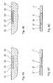
- Figure 1shows a schematic partial section through an arrangement for carrying out a preferred variant of the method according to the invention with an implant 1, in whose base body 2 a recess 4 is provided. In this recess 4, a solidifiable, pourable material mixture in the form of granules 5 was filled.
- the implantis the example shown a stent 1 with a tubular body 2. It is understood, however, that the invention can also be used in connection with any other implants of their application. It is further understood that in this case any materials for the main body of the implant can be used. It is only necessary that then the flowable or pourable material or material mixture is tuned thereto.
- the solidified granules 5forms a marker element in the form of an X-ray marker 6.
- the granules 5are solidified in a process which comprises an endothermic step. In this endothermic step, the granules 5 are supplied with so much energy that sintering of the granules 5 occurs. In this case, the granules 5 of the granules melt on their surface and thus fuse together in the areas in which they rest against each other. In a further step, the material cools again and then forms a solid, which then forms the X-ray marker 6 due to the resulting connections between the grains of the granules 5. This condition is shown in FIG.
- a laser 7is provided, with which the granules 5 are selectively irradiated in order to introduce the process energy into the granules 5 for the endothermic step.
- the laserradiates along its beam axis 8 on the granules 5.
- the laser 7can be moved in the direction of the double arrow 9 in order to supply the entire granules 5 sufficient process energy.
- the amount of radiant energy introduced in the edge region of the recess 3is controlled in such a way that melting of the material of the base body 2 occurs at the interface 10 between the granules 5 and the base body 2.
- the grains 11 of the granules 5thus merge superficially with the main body 2, so that a kind of welded joint between the X-ray marker 6 and the base body 2 results.
- the granulate 5consists of a mixture of materials of radiopaque particles 12, which consists of a layer 13 of material which can be melted by the laser radiation. It is understood, however, that in other preferred variants instead of a material mixture also at least superficially fusible powder or granules of a single, then corresponding radiopaque material can be used.
- the method of attaching the X-ray marker 6is as follows. In order to allow the filling of the granules 5 into the recess 3, the recess 3, which is open on both sides, is closed on its underside by a closure element 14. In the recess 3 in the main body. 2 of the implant 1 is then filled with such a large amount of the granules 5, that the recess 3 is filled almost completely. Subsequently, the endothermic step takes place, in which by means of the laser 7, the granules 5 and the edge 3 bounding the edge region of the base body 2 in the manner described above, energy is supplied. Subsequently, the sintered granulate 5 cools again and thus forms the x-ray marker 6 firmly connected to the main body 2.
- FIG. 3shows an alternative arrangement for carrying out a variant of the method according to the invention. This is similar in its basic sequence to that described with reference to FIGS. 1 and 2, so that only the differences should be discussed here.
- edge regions 10 'of the base body 2' delimiting the recess 3 'have a particularly high electrical resistance in order to achieve a particularly large local heating in this region, which in turn results in a description of FIGS. 1 and 2 local merging of the grains of the granules 5 'with the main body 2' leads.
- the high resistancewas achieved by oxidation of these edge regions 10 '. It is understood, however, that it can be accomplished in any other way.
- an additional mold element 17is provided. This is in addition to the closure element 14 'in the region of the upper opening of the recess 3' in the base body 2 'of the implant 1' arranged.
- the closure element 14 'and the mold element 17are formed and the filling quantity of the granules 5' is selected such that undercuts between the base body 2 'and the X-ray marker 6' result.
- an X-ray marker 6 'results, which surrounds the edge region of the recess 3'.
- a stampas indicated by the dashed contour 18, be provided, which is movable along the arrow 19.
- the granules 5 'can be pressurized during sintering to improve the sintering result.
- closure element, the mold element and / or the stampcan be formed individually or in combination as heating elements in order to provide the process energy for the endothermic step.
- closure member 14 'in the example shownhas correspondingly smaller dimensions than the interior of the stent, so that it can be radially removed from the stent after completion of the X-ray marker 6' and axially.
- FIG. 4Ashows a variant of an implant 20 according to the invention with a recess 21 in the form of a cavity in a base body 22.
- the recess 21is potted with a flowable suspension of radio-opaque particles 23 in a hardening plastic 24 which forms the X-ray marker 25 in the cured state.
- FIG. 4Bshows a further variant of an implant 20 'according to the invention with a recess 21' in the form of a cavity in a base body 22 '.
- the recess 21 'is potted with a flowable, hardening plastic 24', in which in turn a radiopaque element 23 ' is embedded.
- the element 23 'forms, together with the cured plastic bed 24', the X-ray marker 25 '.
- FIG. 4Cshows a further variant of a stent 1 "according to the invention.
- the difference to the stent illustrated in FIG. 1is that the recess 3" in the base body 2 "was filled with a viscous suspension in a dipping process, as described in principle with respect to FIG.
- the connection between the resulting X-ray marker 6 "and the base body 2"results from adhesion of the material of the X-ray marker 6 "to the base body 2".
- FIG. 4Dshows a further variant of the stent 1 "according to the invention with an X-ray marker 26.
- the difference to the stent illustrated in FIG. 1is, on the one hand, that one or more undercuts 27 are provided in the region of the basic body 2" delimiting the recess 3 ", which ensure a positive connection between the base body 2 "and the X-ray marker 26.
- the material used for the X-ray marker 26is a cold-curing amalgam known from the field of dentistry, which has excellent X-ray opacity. The material was introduced in its pasty, uncured state in the recess 3 "and could then harden there.
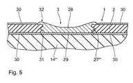
- Figure 5shows a schematic partial section through a further preferred embodiment of the implant in the form of a stent 1 "'with a base body 2"', in which a recess 3 "'is located by galvanic deposition of a radiopaque material, in the present case gold, an X-ray marker 28 introduced and solidified.
- the stent 1 "'is shown in Figure 5 in a state in which the electrodeposition has just been completed.
- the stent 1 "'is introduced into a galvanic solution in which a galvanic deposition process then takes place in a known manner."
- the main body 2 "' of the stent 1"'forms a part of the deposition electrode on which the material is deposited of the X-ray marker 28 attaches.
- a further part of the deposition electrodeis formed by a thin, conductive coating 29 on the closure element 14"' arranged in the interior of the stent 1 "', which defines the recess 3 '' limiting edge region of the body 2 '' conductively contacted.
- an easily removable protective coating 30in the areas in which no deposition is to take place Accumulation prevented.
- Thismay be, for example, a wax or fat layer or the like.
- the coating 29adheres to the X-ray marker 28 and detaches from the closure element 14"'. This is particularly useful if the coating anyway consists of the same material as the X-ray marker 28, since then a particularly good connection is ensured.
- the coatinganyway consists of the same material as the X-ray marker 28, since then a particularly good connection is ensured.
- the part of the deposition electrode forming, electrically conductive coatingcan solve in other variants of the invention when removing the closure element and the X-ray marker, so that the X-ray marker then only from the electrodeposited material - optionally with the deposits described etc. - exists.
- particles or parts of another, or possibly even of the same materialmay also be embedded in the electrodeposited material.
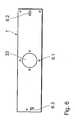
- FIG. 6shows a schematic plan view of the stent 1 from FIGS. 1 and 2.
- Thisis a so-called bifurcation stent, which is used in the region of vessel branches.
- ithas a lateral opening 33, which is characterized by X-ray marker 6.1.
- the stent 1further X-ray markers 6.2 and 6.3. These serve on the one hand to mark the ends of the stent 1.
- its shape and the number of X-ray markers 6.2 and 6.3are chosen so that they provide the surgeon with different information regarding the stent.
- the shape and number of the X-ray markers 6.2provide information about the date of manufacture of the stent 1
- the shape and number of the X-ray markers 6.3represent a product identifier for the stent. It goes without saying that any other information regarding the stent can also be reproduced by the form, number and arrangement of the x-ray markers.
- the marker elements according to the inventioncan be introduced not only in separately provided recesses in the stent wall. Likewise, you can be introduced in an advantageous manner by the network structure of the stent wall predetermined recesses. They can be distributed as desired over the stent.
Landscapes
- Health & Medical Sciences (AREA)
- Life Sciences & Earth Sciences (AREA)
- Engineering & Computer Science (AREA)
- Biomedical Technology (AREA)
- Animal Behavior & Ethology (AREA)
- Veterinary Medicine (AREA)
- Oral & Maxillofacial Surgery (AREA)
- Public Health (AREA)
- Surgery (AREA)
- Heart & Thoracic Surgery (AREA)
- General Health & Medical Sciences (AREA)
- Molecular Biology (AREA)
- Medical Informatics (AREA)
- Pathology (AREA)
- Nuclear Medicine, Radiotherapy & Molecular Imaging (AREA)
- Cardiology (AREA)
- Transplantation (AREA)
- Vascular Medicine (AREA)
- Prostheses (AREA)
- Media Introduction/Drainage Providing Device (AREA)
Description
Translated fromGermanDie vorliegende Erfindung betrifft ein Verfahren zum Anbringen eines Markerelements an einem zum Implantieren in den menschlichen oder tierischen Körper vorgesehenen Implantat, insbesondere einem Stent, mit einem Grundkörper und einer in diesem Grundkörper vorgesehenen Ausnehmung zur Aufnahme des Markerelements. Weiterhin betrifft sie ein Implantat, insbesondere einen Stent, welches mit einem solchen Markerelement versehen ist.The present invention relates to a method for attaching a marker element to an implant intended for implantation in the human or animal body, in particular a stent, having a base body and a recess provided in this base body for receiving the marker element. Furthermore, it relates to an implant, in particular a stent, which is provided with such a marker element.
Eine Vielzahl derzeit gebräuchlicher Implantate werden in den menschlichen oder tierischen Körper beispielsweise unter Zuhilfenahme von Katheter oder dergleichen eingesetzt, ohne dass der Chirurg die Implantationsstelle direkt einsehen kann.A variety of currently used implants are used in the human or animal body, for example with the aid of catheters or the like, without the surgeon can see the implantation site directly.
Häufig ist es daher erforderlich, dass die korrekte Position des Implantats mit anderen Mitteln nachvollzogen wird. Hierzu werden meist bildgebende, beispielsweise mit Röntgenstrahlen arbeitende Geräte eingesetzt, welche es dem Chirurgen erlauben, anhand der erhaltenen Abbildungen die Positionierung des Implantats zu beurteilen.Often it is therefore necessary that the correct position of the implant is understood by other means. For this purpose, mostly imaging, for example, using X-rays devices are used, which allow the surgeon to judge the positioning of the implant based on the images obtained.
Da viele Implantatwerkstoffe keinen ausreichend kontrastreichen Bildeindruck auf den mit den derzeit gebräuchlichen Methoden gewonnenen Abbildungen hinterlassen, werden in der Regel so genannte Marker an definierten Positionen am Implantat angebracht. Der Werkstoff dieser Marker desto gewählt, dass er einen ausreichend kontrastreichen Bildeindruck ergibt, welcher Rückschlüsse auf die Position des Implantats zulässt.Since many implant materials do not leave a sufficiently high-contrast image impression on the images obtained with the methods currently in use, so-called markers are usually attached to the implant at defined positions. The material of these markers is chosen so that it gives a sufficiently high-contrast image impression, which allows conclusions about the position of the implant.
Derartige Marker bestehen in der Regel aus Festkörpern, welche für die zur Bildgebung verwendete Strahlung undurchlässig sind. Ein solcher Festkörper ist in die Ausnehmung im Grundkörper des Implantats eingesetzt und mit dem Grundkörper durch Verpressen und zusätzlich oder alternativ durch Verschweißen verbunden.Such markers usually consist of solids which are impermeable to the radiation used for imaging. Such a solid body is inserted into the recess in the base body of the implant and connected to the base body by pressing and additionally or alternatively by welding.
So ist beispielsweise aus der
Beide Varianten weisen den Nachteil auf, dass das Implantat im Bereich der Ausnehmung beim Verpressen teils recht hohen mechanischen Belastungen unterworfen ist. Gerade der relativ fragilen Gebilden, wie sie beispielsweise Stents darstellen, kann es in diesem Bereich schnell zu einer unerwünschten Beschädigung des Grundkörpers kommen. Diese ist besonders schädlich, wenn sie nicht sofort erkennbar ist und es gegebenenfalls erst im implantierten Zustand zum Versagen kommt. So kann es beispielsweise bei einen Stent zu unerwünschten scharfen Bruchkanten kommen, welche möglicherweise sogar das umliegende Gewebe schädigen. Ebenso kann es natürlich auch zu einem unerwünschten Lösen das Markerelements vom Implantat kommen.Both variants have the disadvantage that the implant is subjected in the region of the recess during pressing partly quite high mechanical loads. Especially the relatively fragile structures, such as represent stents, it can quickly come in this area to an undesirable damage to the body. This is particularly harmful if it is not immediately recognizable and it may not fail until implanted. So it can, for example, at a Stent come to unwanted sharp edges, which may even damage the surrounding tissue. Likewise, it may of course also come to an undesired release of the marker element from the implant.
Bei anderen bekannten Varianten wird das Markerelement mit dem angrenzenden Grundkörper des Implantats verschweißt. Dies ist beispielsweise für einen Stent aus der
Der vorliegenden Erfindung liegt da die Aufgabe zu Grunde, ein gattungsgemäßes Verfahren zum Anbringen eines Markerelements an einem Implantat sowie ein gattungsgemäßes Implantat zur Verfügung zu stellen, die die obengenannten Nachteile nicht oder zumindest in geringerem Maße aufweisen und insbesondere eine einfache und flexible Herstellung gewährleisten.It is an object of the present invention to provide a generic method for attaching a marker element to an implant as well as a generic implant which do not or at least to a lesser extent have the abovementioned disadvantages and in particular ensure simple and flexible production.
Diese Aufgabe wird ausgehend von einem Verfahren gemäß dem Oberbegriff des Anspruchs 1 durch die im kennzeichnenden Teil des Anspruchs 1 angegebenen Merkmale gelöst. Ebenso wird sie ausgehend von einem Implantat gemäß dem Oberbegriff des Anspruchs 12 durch die im kennzeichnenden Teil des Anspruchs 12 angegebenen Merkmale gelöst.This object is achieved on the basis of a method according to the preamble of
Der vorliegenden Erfindung liegt die technische Lehre zu Grunde, dass man eine besonders einfache und flexible Herstellung eines Implantats mit einem in einer Ausnehmung des Grundkörpers des Implantats angeordneten Markerelement erzielt, wenn zur Ausbildung wenigstens eines Teils des Markerelements ein verfestigbares Material oder Materialgemisch in die Ausnehmung eingebracht und dort verfestigt wird.The present invention is based on the technical teaching that a particularly simple and flexible production of an implant is achieved with a marker element arranged in a recess of the basic body of the implant, if a solidifiable material or material mixture is introduced into the recess to form at least a part of the marker element and solidified there.
Bei dem eingebrachten Material oder Materialgemisch handelt es sich bevorzugt um ein fließ- oder schüttfähiges Material oder Materialgemisch. Durch die Fließ- bzw. Schüttfähigkeit des verwendeten verfestigbaren Materials bzw. Materialgemisches ist zum einen sichergestellt, dass sich das entstehende Markerelement ohne weiteres an beliebige Geometrieen der Ausnehmung anpasst. Dies hat zum einen der Folge, dass eine besonders hohe Flexibilität bei der Gestaltung der Ausnehmungen besteht und zum anderen bei deren Fertigung keine besonderen Maßtoleranzen oder dergleichen einzuhalten sind. Hierdurch erleichtert sich die Fertigung des Implantats erheblich.The introduced material or material mixture is preferably a flowable or pourable material or material mixture. On the one hand, it is ensured by the flowability or pourability of the solidifiable material or material mixture used that the resulting marker element readily adapts to any desired geometry of the recess. This has, on the one hand, the consequence that there is a particularly high degree of flexibility in the design of the recesses and, on the other hand, that no special dimensional tolerances or the like are to be observed during their production. As a result, the production of the implant facilitates considerably.
Ein weiterer Vorteil der erfindungsgemäßen Lösung liegt darin, dass beim Anbringen des Markerelements keine übermäßig hohen Spannungen zwischen dem Markerelement und dem angrenzenden Grundkörper des Implantats auftreten, sodass weder das Markerelement noch der Grundkörper des Implantats übermäßigen mechanischen Belastungen, insbesondere hohen Vorspannungen unterworfen sind. Die Wahrscheinlichkeit, dass es bei der Herstellung oder im Einsatz zu einem Versagen des Markerelements oder des angrenzenden Grundkörpers kommt, ist somit gegenüber den aus dem Stand der Technik bekannten Varianten erheblich reduziert.Another advantage of the solution according to the invention is that when attaching the marker element no excessively high voltages between the marker element and the adjacent base body of the implant occur, so that neither the marker element nor the main body of the implant are subjected to excessive mechanical loads, in particular high biases. The probability that the marker element or the adjoining main body will fail during production or use is thus considerably reduced compared to the variants known from the prior art.
Bei dem verwendeten Material bzw. Materialgemisch kann es sich um ein beliebiges ausreichend biokompatibles Material bzw. Materialgemisch handeln, welches ausreichend verfestigbar ist, um ein ausreichend stabiles Markerelement sowie einen ausreichend sicheren Verbund zwischen dem Markerelement und dem angrenzenden Grundkörper herzustellen.The material or material mixture used may be any sufficiently biocompatible material or material mixture which is sufficiently solidifiable to produce a sufficiently stable marker element and a sufficiently secure bond between the marker element and the adjoining base body.
Das verwendete Material bzw. Materialgemisch bildet dabei vorzugsweise das gesamte Markerelement. Hierzu kann es aus einer einzelnen entsprechend verfestigbaren Komponente bestehen, die zudem eine ausreichende Undurchlässigkeit für die zur Bildgebung verwendete Strahlung aufweist.The material or material mixture used preferably forms the entire marker element. For this purpose, it may consist of a single suitably solidifiable component, which also has sufficient impermeability to the radiation used for imaging.
Die Erfindung besteht darin, dass Partikel oder größere Teile eines entsprechend strahlungsundurchlässigen Materials einem entsprechenden verfestigbaren Material bzw. Materialgemisch beigemischt sind. So ist es beispielsweise denkbar, dass das schüttfähige Material bzw. Materialgemisch aus einem Granulat besteht, dessen Körner aus einem oder mehreren Partikeln eines entsprechend strahlungsundurchlässigen Materials bestehen, die von einem verfestigbaren Material bzw. Materialgemisch umschlossen sind. Ebenso ist es möglich, die Ausnehmung mit einer Suspension aus einem aushärtenden flüssigen Material bzw. Materialgemisch und solchen strahlungsundurchlässigen Partikeln auszugießen. Im Endergebnis können aber auch größere Teile aus einem solchen strahlungsundurchlässigen Material ganz oder teilweise von einem entsprechenden verfestigbaren Material umschlossen sein.The invention consists in that particles or larger parts of a correspondingly radiation-impermeable material are admixed with a corresponding solidifiable material or material mixture. For example, it is conceivable that the pourable material or material mixture of a Granules whose grains consist of one or more particles of a corresponding radiopaque material, which are enclosed by a solidifiable material or material mixture. Likewise, it is possible to pour out the recess with a suspension of a hardening liquid material or material mixture and such radiopaque particles. In the final result, however, larger parts of such a radiopaque material may be completely or partially enclosed by a corresponding solidifiable material.
Eine weitere Variante stellen fließfähige oder pastöse, verfestigbare und entsprechend strahlungsundurchlässige Materialien, wie beispielsweise das aus der Zahnheilkunde bekannte Amalgam, dar, welche ohne Energiezufuhr, d. h. kalt aushärten. Es versteht sich, dass natürlich auch diese in Verbindung mit den genannten eingeschlossenen oder umschlossenen Partikeln bzw. Teilen eingesetzt werden können.Another variant is flowable or pasty, solidifiable and corresponding radiopaque materials, such as the well-known from dentistry amalgam, which without energy, d. H. cure cold. It goes without saying that, of course, these can also be used in conjunction with the mentioned enclosed or enclosed particles or parts.
Es ist bei allen diesen Varianten lediglich erforderlich, dass ein ausreichend stabiler mechanischer Verbund zwischen dem Grundkörper, dem verfestigbaren Material bzw. Materialgemisch und gegebenenfalls den Teilen aus dem strahlungsundurchlässigen Material erzielt wird. Hierzu können durch eine entsprechende Gestaltung des Grundkörpers im Bereich, der die Ausnehmung begrenzt, oder durch die Verwendung entsprechender Formen etc. beim Verfüllen der Ausnehmung mit dem fließfähigen oder schüttfähigen Material bzw. Materialgemisch Hinterschneidungen zwischen dem Grundkörper und dem sich ergebenden Markerelement erzeugt werden, die eine formschlüssige Verbindung zwischen Grundkörper und Markerelement bewirken. Ebenso ist es aber möglich, dass dieser stabile Verbund zusätzlich oder alternativ auch dadurch erzielt wird, dass das fließ- oder schüttfähige Material oder Materialgemisch während des Verfestigungsvorgangs mit dem Material des Grundkörpers verbunden wird. Dies kann durch Adhäsion oder durch eine Materialverschmelzung, beispielsweise ein Verschweißen, erfolgen. Als Materialien für das verfestigbare Material bzw. Materialgemisch kommen sowohl Kunststoffe bzw. Kunststoffgemische, Metalle bzw. Metalllegierungen sowie Keramiken in Betracht.All of these variants merely require that a sufficiently stable mechanical bond is achieved between the base body, the solidifiable material or material mixture and, if appropriate, the parts made of the radiopaque material. For this purpose, by an appropriate design of the body in the area that limits the recess, or by the use of appropriate shapes, etc. when filling the recess with the flowable or pourable material or material mixture undercuts between the body and the resulting marker element are generated effect a positive connection between the base body and marker element. However, it is also possible that this stable composite is achieved additionally or alternatively also by connecting the flowable or pourable material or material mixture to the material of the base body during the solidification process. This can be done by adhesion or by a material fusion, such as welding. Suitable materials for the solidifiable material or material mixture are both plastics or plastic mixtures, metals or metal alloys and ceramics into consideration.
Bei bevorzugten der Varianten des erfindungsgemäßen Verfahrens ist vorgesehen, dass das fließ- oder schüttfähige Material oder Materialgemisch ein sinterfähiges Granulat oder Pulver ist, das in der Ausnehmung durch Sintern verfestigt wird, da ein solches Granulat oder Pulver eine besonders einfache Handhabung ermöglichen.In preferred variants of the method according to the invention it is provided that the flowable or free-flowing material or material mixture is a sinterable granules or powder, which is solidified in the recess by sintering, since such a granulate or powder allow a particularly simple handling.
Vorteilhafte Ausgestaltungen des erfindungsgemäßen Verfahrens zeichnen sich dadurch aus, dass der Verfestigungsvorgang einen endothermen Schritt umfasst und wenigstens ein Teil der Prozessenergie in dem endothermen Schritt lokal im Bereich der Ausnehmung eingebracht wird. Hierdurch lässt sich in vorteilhafter Weise eine besonders gezielte und gut steuerbare Verfestigung mit dem Ergebnis sowohl eines stabilen Markerelements als auch einer stabilen Verbindung zwischen dem Markerelement und dem Grundkörper.Advantageous embodiments of the method according to the invention are characterized in that the solidification process comprises an endothermic step and at least a portion of the process energy is introduced locally in the region of the recess in the endothermic step. As a result, a particularly targeted and well controllable solidification can be achieved with the result of both a stable marker element and a stable connection between the marker element and the base body.
Die Prozessenergie kann dabei in beliebiger, auf das zu verfestigende Material bzw. Materialgemische abgestimmter Weise gezielt lokal eingebracht werden. Vorzugsweise wird sie in dem endothermen Schritt durch gezielte Bestrahlung des im Bereich der Ausnehmung angeordneten Materials bzw. Materialgemisches eingebracht. Hierbei kann beispielsweise ein Laser verwendet werden, da sich dieser besonders einfach und gut gezielt einsetzen lässt. Es sind jedoch auch beliebige andere Varianten der Energieeinbringung einsetzbar. So kann beispielsweise ein Pulver oder Granulat zu mechanischen Schwingungen angeregt werden, die dann auf Grund der Reibung zwischen den Partikeln eine Erwärmung bewirken. Eine solche Anregung kann beispielsweise mittels Ultraschall erfolgen. Ebenso können aber auch gezielt entsprechend geformte Heizflächen bzw. Heizelemente oder dergleichen eingesetzt werden. Diese können zusätzlich dazu verwendet werden, Druck auf das zu verfestigende Material bzw. Materialgemisch auszuüben. Solche Stempel etc. zur Druckerzeugung können natürlich aber auch im Zusammenhang mit den anderen Varianten der Energieeinbringung eingesetzt werden.The process energy can be deliberately introduced locally in any manner that is tailored to the material or material mixtures to be consolidated. In the endothermic step, it is preferably introduced by targeted irradiation of the material or material mixture arranged in the region of the recess. In this case, for example, a laser can be used, since this can be used in a particularly simple and targeted manner. However, it is also possible to use any other variants of the energy input. For example, a powder or granules can be excited to mechanical vibrations, which then cause heating due to the friction between the particles. Such an excitation can be done for example by means of ultrasound. Likewise, however, also suitably shaped heating surfaces or heating elements or the like can be used. These can additionally be used to exert pressure on the material or material mixture to be consolidated. Of course, such stamps etc. for generating pressure can also be used in connection with the other variants of energy input.
Bei anderen Varianten wird wenigstens ein Teil der Prozessenergie in dem endothermen Schritt elektrisch durch Erzeugung eines Stromflusses durch das im Bereich der Ausnehmung angeordnete fließ- oder schüttfähige Material oder Materialgemisch eingebracht. Hierbei kann das Material bzw. Materialgemisch so gewählt sein, dass es für den Strom einen großen Widerstand darstellt, mit dem Ergebnis, dass in ihm ein großer Teil der zugeführten Energie in Wärme umgesetzt wird.In other variants, at least part of the process energy in the endothermic step is electrically generated by generating a current flow through the flowable or free-flowing material arranged in the region of the recess or mixed material introduced. Here, the material or material mixture may be chosen so that it represents a large resistance to the current, with the result that in him a large part of the supplied energy is converted into heat.
Es versteht sich, dass die angeführten Möglichkeiten der Einbringung der Prozessenergie in dem endothermen Schritt auch beliebig miteinander kombiniert werden können.It is understood that the stated possibilities of introducing the process energy in the endothermic step can also be combined as desired.
Die vorliegende Erfindung betrifft weiterhin ein Implantat, insbesondere einen Stent, zum Implantieren in den menschlichen oder tierischen Körper mit einem in der oben beschriebenen Weise hergestellten bzw. angebrachten Markerelement, welcher gleichermaßen die oben beschriebenen Vorteile aufweist.The present invention further relates to an implant, in particular a stent, for implantation in the human or animal body with a marker element manufactured in the manner described above, which likewise has the advantages described above.
Bei besonders bevorzugten Varianten des erfindungsgemäßen Implantats sind die Ausnehmung und zusätzlich oder alternativ das Markerelement sowie zusätzlich oder alternativ deren Anordnung bezüglich des Grundkörpers zur Kennzeichnung wenigstens einer Eigenschaft des Implantats ausgebildet. Ebenso ist es aber möglich durch die Gestalt bzw. die Anordnung eines Markerelements oder mehrerer Markerelemente zueinander eine solche Kennzeichnung zu bewerkstelligen. Hierbei kann es beispielsweise um eine Produktkennzeichnung handeln. Ebenso ist es auch möglich, in dieser Weise beliebige andere Informationen mit Implantat zu verknüpfen. So kann sich in der geschilderten Weise z. B. das Herstellungsdatum, das Material etc. des Implantats ergeben.In particularly preferred variants of the implant according to the invention, the recess and additionally or alternatively the marker element and additionally or alternatively their arrangement with respect to the base body for identifying at least one property of the implant are formed. However, it is also possible by the shape or the arrangement of a marker element or several marker elements to each other to accomplish such identification. This may, for example, be a product identification. Likewise, it is also possible to link in this way any other information with implant. Thus, in the described manner z. As the date of manufacture, the material, etc. of the implant.
Ebenso ermöglicht die Erfindung, mit geringem Aufwand Markierungen in Bereichen des Implantats Anbringen, wie von besonderem Interesse sind. So ist es beispielsweise bei einem zum Einsatz im Bereich von Gefäßverzweigungen vorgesehenen so genannten Bifurkationsstent möglich, die seitlichen Öffnungen einfach in der geschilderten Weise zu kennzeichnen.Likewise, the invention allows, with little effort attaching marks in areas of the implant attaching, as are of particular interest. Thus, for example, in the case of a so-called bifurcation stent provided for use in the area of vessel branches, it is possible to simply mark the lateral openings in the manner described.
Weitere bevorzugte Ausführungsformen der vorliegenden Erfindung ergeben sich aus den Unteransprüchen bzw. werden nachstehend unter Bezugnahme auf die beigefügten Zeichnungen beschrieben. Es zeigen:
Figur 1- einen schematischen Teilschnitt durch eine Anordnung zur Durchführung einer bevorzugten Variante des erfindungsgemäßen Verfahrens;
Figur 2- eine schematische Schnittansicht des Details
II aus Figur 1; Figur 3- einen schematischen Teilschnitt durch eine Anordnung zur Durchführung einer weiteren bevorzugten Variante des erfindungsgemäßen Verfahrens;
- Figur 4A bis 4D
- schematische Teilschnitte durch bevorzugte Ausführungen des erfindungsgemäßen Implantats;
Figur 5- einen schematischen Teilschnitt durch eine weitere Ausführung des Implantats, nicht Teil der Erfindung.
Figur 6- eine schematische Draufsicht auf eine bevorzugte Ausführung eines erfindungsgemäßen Stents.
- FIG. 1
- a schematic partial section through an arrangement for carrying out a preferred variant of the method according to the invention;
- FIG. 2
- a schematic sectional view of the detail II of Figure 1;
- FIG. 3
- a schematic partial section through an arrangement for carrying out a further preferred variant of the method according to the invention;
- FIGS. 4A to 4D
- schematic partial sections through preferred embodiments of the implant according to the invention;
- FIG. 5
- a schematic partial section through a further embodiment of the implant, not part of the invention.
- FIG. 6
- a schematic plan view of a preferred embodiment of a stent according to the invention.
Figur 1 zeigt einen schematischen Teilschnitt durch eine Anordnung zur Durchführung einer bevorzugten Variante des erfindungsgemäßen Verfahrens mit einem Implantat 1, in dessen Grundkörper 2 eine Ausnehmung 4 vorgesehen ist. In diese Ausnehmung 4 wurde ein verfestigbares, schüttfähiges Materialgemisch in Form eines Granulats 5 eingefüllt.Figure 1 shows a schematic partial section through an arrangement for carrying out a preferred variant of the method according to the invention with an
Das Implantat ist dem gezeigten Beispiel ein Stent 1 mit einem rohrförmigen Grundkörper 2. Es versteht sich jedoch, dass die Erfindung auch im Zusammenhang mit beliebigen anderen Implantaten ihrer Anwendung finden kann. Es versteht sich weiterhin, dass hierbei beliebige Materialien für den Grundkörper des Implantats Anwendung finden können. Es ist lediglich erforderlich, dass dann das fließfähige oder schüttfähige Material bzw. Materialgemisch hierauf abgestimmt ist.The implant is the example shown a
Das verfestigte Granulat 5 bildet ein Markerelement in Form eines Röntgenmarkers 6. Das Granulat 5 wird in einem Vorgang verfestigt, der einen endothermen Schritt umfasst. In diesem endothermen Schritt wird den Granulat 5 so viel Energie zugeführt, dass es zu einem Versintern der Körner des Granulats 5 kommt. Hierbei schmelzen die Körner des Granulats 5 an ihrer Oberfläche auf und verschmelzen so miteinander in den Bereichen, in denen sie aneinander anliegen. In einem weiteren Schritt kühlt das Material wieder ab und bildet dann auf Grund der sich ergebenden Verbindungen zwischen den Körnern des Granulat 5 einen Festkörper, der dann den Röntgenmarker 6 bildet. Dieser Zustand ist in Figur 2 dargestellt.The solidified
Um das Granulat 5 zur Ausbildung des Röntgenmarkers 6 zu verfestigen ist ein Laser 7 vorgesehen, mit dem das Granulat 5 gezielt bestrahlt wird, um die Prozessenergie für den endothermen Schritt in das Granulat 5 einzubringen. Der Laser strahlt dabei entlang seiner Strahlachse 8 auf das Granulat 5. Der Laser 7 kann in Richtung des Doppelpfeils 9 verfahren werden, um den gesamten Granulat 5 ausreichend Prozessenergie zuzuführen. Dabei wird die im Randbereich der Ausnehmung 3 eingebrachte Strahlungsenergiemenge so geregelt, dass es an der Grenzfläche 10 zwischen den Granulat 5 und dem Grundkörper 2 zusätzlich zu einem Aufschmelzen des Materials des Grundkörpers 2 kommt. Die Körner 11 des Granulats 5 verschmelzen somit oberflächlich mit dem Grundkörper 2, sodass sich eine Art Schweißverbindung zwischen dem Röntgenmarker 6 und dem Grundkörper 2 ergibt.In order to solidify the
Das Granulat 5 besteht, wie Figur 2 zu entnehmen ist, aus einem Materialgemisch aus röntgenundurchlässigen Partikeln 12, die von einer Schicht 13 aus durch die Laserstrahlung aufschmelzbarem Material besteht. Es versteht sich jedoch, dass bei anderen bevorzugten Varianten an Stelle eines Materialgemisches auch zumindest oberflächlich aufschmelzbare Pulver- oder Granulatkörner aus einem einzigen, dann entsprechend strahlungsundurchlässigen Material Verwendung finden können.As can be seen from FIG. 2, the
Das Verfahren zum Anbringen des Röntgenmarkers 6 läuft wie folgt ab. Um das Einfüllen des Granulats 5 in die Ausnehmung 3 zu ermöglichen wird die zu beiden Seiten offene Ausnehmung 3 an ihrer Unterseite mit einem Verschlusselement 14 verschlossen. In die Ausnehmung 3 im Grundkörper 2 des Implantats 1 wird dann eine so große Menge des Granulats 5 eingefüllt, dass die Ausnehmung 3 annähernd vollständig verfüllt ist. Anschließend erfolgt der endotherme Schritt, in dem mittels des Lasers 7 den Granulat 5 sowie dem die Ausnehmung 3 begrenzenden Randbereich des Grundkörpers 2 in der oben beschriebenen Weise Energie zugeführt wird. Anschließend kühlt das versinterte Granulat 5 wieder ab und bildet so den fest mit dem Grundkörper 2 verbundenen Röntgenmarker 6.The method of attaching the
Figur 3 zeigt eine alternative Anordnung zur Durchführung einer Variante des erfindungsgemäßen Verfahrens. Diese gleicht in ihrem grundsätzlichen Ablauf derjenigen, die zu den Figuren 1 und 2 beschrieben wurde, sodass hier lediglich auf die Unterschiede eingegangen werden soll.FIG. 3 shows an alternative arrangement for carrying out a variant of the method according to the invention. This is similar in its basic sequence to that described with reference to FIGS. 1 and 2, so that only the differences should be discussed here.
Ein Unterschied besteht in der Einbringung der Prozessenergie in dem endothermen Schritt des Verfahrens. Diese wird im gezeigten Beispiel über einen elektrischen Gleichstrom mittels der Kontakte 15 und 16 eingebracht, welche den elektrisch leitenden Grundkörper 2' des Implantats 1' kontaktieren. Die Kontakte 15 und 16 sind so angeordnet, dass der elektrische Gleichstrom durch das Granulat 5' fließt. Der elektrische Widerstand des Granulats 5', das im gezeigten Beispiel aus Körnern eines einzigen röntgenundurchlässigen Materials besteht, ist so groß, dass es infolge des Stromflusses im wesentlichen in der gesamten Granulatschüttung zu einer Erwärmung kommt, die ein Versintern der Körner des Granulats 5' in der zu Figur 1 und 2 beschriebenen Weise sicherstellt.One difference is the introduction of process energy in the endothermic step of the process. In the example shown, this is introduced via an electrical direct current by means of the
Ein zusätzlicher Unterschied besteht darin, dass die die Ausnehmung 3' begrenzenden Randbereiche 10' des Grundkörpers 2' einen besonders hohen elektrischen Widerstand aufweisen, um in diesem Bereich eine besonders große lokale Erwärmung zu erzielen, welche wiederum zu einem zu den Figuren 1 und 2 beschriebenen lokalen Verschmelzen der Körner des Granulats 5' mit dem Grundkörper 2' führt. Der hohe Widerstand wurde dabei durch eine Oxidation dieser Randbereiche 10' erzielt. Es versteht sich jedoch, dass er auch in beliebiger anderer Weise bewerkstelligt werden kann.An additional difference is that the edge regions 10 'of the base body 2' delimiting the recess 3 'have a particularly high electrical resistance in order to achieve a particularly large local heating in this region, which in turn results in a description of FIGS. 1 and 2 local merging of the grains of the granules 5 'with the main body 2' leads. The high resistance was achieved by oxidation of these edge regions 10 '. It is understood, however, that it can be accomplished in any other way.
Ein weiterer Unterschied zur Variante aus Figur 1 besteht darin, dass eine zusätzliches Formelement 17 vorgesehen ist. Dieses ist zusätzlich zum Verschlusselement 14' im Bereich der oberen Öffnung der Ausnehmung 3' im Grundkörper 2' des Implantats 1' angeordnet. Das Verschlusselement 14' und das Formelement 17 sind dabei so ausgebildet und die Füllmenge des Granulats 5' ist so gewählt, dass sich Hinterschneidungen zwischen dem Grundkörper 2' und dem Röntgenmarker 6' ergeben. Mit anderen Worten ergibt sich ein Röntgenmarker 6', welcher den Randbereich der Ausnehmung 3' umgreift.Another difference to the variant of Figure 1 is that an
Um das Sintern des Granulats 5' zu unterstützen kann ein Stempel, wie er durch die gestrichelte Kontur 18 angedeutet ist, vorgesehen sein, der entlang des Pfeiles 19 verfahrbar ist. Mittels dieses Stempels kann das Granulat 5' beim Versintern mit Druck beaufschlagt werden, um das Sinterergebnis zu verbessern.In order to support the sintering of the granules 5 ', a stamp, as indicated by the dashed
Es versteht sich, dass bei anderen Varianten des erfindungsgemäßen Verfahrens auch das Verschlusselement, das Formelement und/oder der Stempel einzeln oder in Kombination als Heizelemente ausgebildet sein können, um die Prozessenergie für den endothermen Schritt zur Verfügung zu stellen.It is understood that in other variants of the method according to the invention, the closure element, the mold element and / or the stamp can be formed individually or in combination as heating elements in order to provide the process energy for the endothermic step.
Es versteht sich weiterhin, dass das Verschlusselement 14' in dem gezeigten Beispiel entsprechend geringere Abmessungen als der Innenraum des Stents aufweist, sodass es nach Fertigstellung des Röntgenmarkers 6' radial von diesem entfernt und axial aus dem Stent herausgeführt werden kann.It is further understood that the closure member 14 'in the example shown has correspondingly smaller dimensions than the interior of the stent, so that it can be radially removed from the stent after completion of the X-ray marker 6' and axially.
Figur 4A zeigt eine Variante eines erfindungsgemäßen Implantats 20 mit einer Ausnehmung 21 in Form einer Aushöhlung in einem Grundkörper 22. Die Ausnehmung 21 ist mit einer fließfähigen Suspension von röntgenundurchlässigen Partikeln 23 in einem aushärtenden Kunststoff 24 vergossen, die im ausgehärteten Zustand den Röntgenmarker 25 bildet.FIG. 4A shows a variant of an
Figur 4B zeigt eine weitere Variante eines erfindungsgemäßen Implantats 20' mit einer Ausnehmung 21' in Form einer Aushöhlung in einem Grundkörper 22'. Die Ausnehmung 21' ist mit einem fließfähigen, aushärtenden Kunststoff 24' vergossen, in dem wiederum einen röntgenundurchlässiges Element 23' eingebettet ist. Das Element 23' bildet zusammen mit dem ausgehärteten Kunststoffbett 24' den Röntgenmarker 25'.FIG. 4B shows a further variant of an implant 20 'according to the invention with a recess 21' in the form of a cavity in a base body 22 '. The recess 21 'is potted with a flowable, hardening plastic 24', in which in turn a radiopaque element 23 ' is embedded. The element 23 'forms, together with the cured plastic bed 24', the X-ray marker 25 '.
Figur 4C zeigt eine weitere Variante eines erfindungsgemäßen Stents 1". Der Unterschied zu dem in Figur 1 dargestellten Stent besteht dabei darin, dass die Ausnehmung 3" im Grundkörper 2" in einem Tauchverfahren mit einer zähflüssigen Suspension verfülllt wurde, wie sie im Grundsatz zur Figur 4A beschrieben wurde. Die Verbindung zwischen dem sich ergebenden Röntgenmarker 6" und dem Grundkörper 2" ergibt sich dabei durch Adhäsion des Materials des Röntgenmarkers 6" an dem Grundkörper 2".4C shows a further variant of a
Figur 4D zeigt eine weitere Variante des erfindungsgemäßen Stents 1" mit einem Röntgenmarker 26. Der Unterschied zu dem in Figur 1 dargestellten Stent besteht zum einen darin, dass im die Ausnehmung 3" begrenzenden Bereich des Grundkörpers 2" eine oder mehrere Hinterschneidungen 27 vorgesehen sind, welche eine formschlüssige Verbindung zwischen dem Grundkörper 2" und dem Röntgenmarker 26 sicherstellen.FIG. 4D shows a further variant of the
Ein weiterer Unterschied besteht darin, dass es sich bei dem für dem Röntgenmarker 26 verwendeten Material um aus der Zahnheilkunde bekanntes, kalt aushärtendes Amalgam handelt, welches hervorragende Röntgenopazität aufweist. Das Material wurde in seinem pastösen, nicht ausgehärteten Zustand in die Ausnehmung 3" eingebracht und konnte dort dann aushärten.Another difference is that the material used for the
Figur 5 (nicht Teil der Erfindung) zeigt einen schematischen Teilschnitt durch eine weitere bevorzugte Ausführung des Implantats in Form eines Stents 1"' mit einem Grundkörper 2"', in dem sich eine Ausnehmung 3"' befindet. In diese Ausnehmung 3"' wurde durch galvanische Abscheidung eines röntgenopaken Materials, im vorliegenden Fall Gold, ein Röntgenmarker 28 eingebracht und verfestigt. Der Stent 1"' ist in Figur 5 in einem Zustand dargestellt, in dem die galvanische Abscheidung soeben abgeschlossen ist.Figure 5 (not part of the invention) shows a schematic partial section through a further preferred embodiment of the implant in the form of a
Zum Herstellen des Röntgenmarkers 8 wird der Stent 1"' in eine galvanische Lösung eingebracht, in der dann in bekannter Weise ein galvanischer Abscheidungsprozess abläuft. Der Grundkörper 2"' des Stents 1"' bildet dabei einem Teil der Ablagerungselektrode, an der sich das Material des Röntgenmarkers 28 anlagert. Um sicherzustellen, dass die Ausnehmung 3"' in der dargestellten Weise ausgefüllt wird, ist ein weiterer Teil der Ablagerungselektrode von einer dünnen, leitenden Beschichtung 29 auf dem im Innern des Stents 1"' angeordneten Verschlusselement 14"' gebildet, welche den die Ausnehmung 3"' begrenzenden Randbereich des Grundkörpers 2"' leitend kontaktiert.In order to produce the
Es versteht sich, dass je nach Geometrie der Ausnehmung gegebenenfalls auch auf eine solche leitende Beschichtung oder dergleichen zum Ausfüllen der Ausnehmung verzichtet werden kann. Vielmehr ist es möglich, dass die Ausnehmung auch ohne ein solches Hilfsmittel im Zuge der galvanischen Abscheidung "zuwächst".It goes without saying that, depending on the geometry of the recess, optionally also such a conductive coating or the like for filling in the recess can be dispensed with. Rather, it is possible that the recess "grows" without such aids in the course of galvanic deposition.
Um zu verhindern, dass sich das Material für den Röntgenmarker 28 an dem gesamten Grundkörper 2"' des Stents 1"' anlagert, ist dieser in den Bereichen, in denen keine Anlagerung stattfinden soll, mit einer leicht entfernbaren Schutzbeschichtung 30 versehen, die eine solche Anlagerung verhindert. Hierbei kann es sich beispielsweise um eine Wachs- oder Fettschicht oder dergleichen handeln.In order to prevent the material for the
Beim späteren Lösen des Verschlusselements 14"' aus dem Stent bleibt die Beschichtung 29 an dem Röntgenmarker 28 haften und löst sich vom Verschlusselement 14"'. Dies ist besonders dann sinnvoll, wenn die Beschichtung ohnehin aus demselben Material wie der Röntgenmarker 28 besteht, da dann eine besonders gute Verbindung sichergestellt ist. Zum anderen ergibt sich mit der gezeigten Konfiguration eine Überlappung 31 zwischen Röntgenmarker 28 und Grundkörper 2"', welche zusammen mit der Überlappung 32 zwischen Röntgenmarker 28 und Grundkörper 2"' zur festen mechanischen Verbindung zwischen Röntgenmarker 28 und Grundkörper 2"' beiträgt.Upon later release of the
Eine weitere derartige mechanische Fixierung ergibt sich durch die Hinterschneidung 27"'. Es versteht sich jedoch, dass diese nicht notwendigerweise vorgesehen sein muss. Ebenso kann diese die beschriebenen Überlappungen ersetzen. Weiterhin kann auch die Haftkraft des Röntgenmarkermaterials an dem Material des Grundkörpers groß genug sein, um eine ausreichende Fixierung des Röntgenmarkers sicherzustellen.Another such mechanical fixation results from the undercut 27 "', but it should be understood that this need not necessarily be provided, and that it can also replace the overlaps described above Furthermore, the adhesive force of the X-ray marker material on the material of the base body can be large enough to ensure sufficient fixation of the X-ray marker.
Es versteht sich im übrigen, dass sich die einen Teil der Ablagerungselektrode bildende, elektrisch leitende Beschichtung bei anderen Varianten der Erfindung beim Entfernen des Verschlusselements auch von dem Röntgenmarker lösen kann, sodass der Röntgenmarker dann nur aus dem galvanisch abgeschiedenen Material - gegebenenfalls mit den beschriebenen Einlagerungen etc. - besteht.It is understood, moreover, that the part of the deposition electrode forming, electrically conductive coating can solve in other variants of the invention when removing the closure element and the X-ray marker, so that the X-ray marker then only from the electrodeposited material - optionally with the deposits described etc. - exists.
Weiterhin versteht es sich, dass wie schon oben insbesondere zu Figur 4B beschrieben in dem galvanisch abgeschiedenen Material auch Partikel oder Teile aus einem anderen oder gegebenenfalls sogar aus demselben Material eingebettet sein können.Furthermore, it is understood that, as described above in particular with reference to FIG. 4B, particles or parts of another, or possibly even of the same material, may also be embedded in the electrodeposited material.
Figur 6 zeigt eine schematische Draufsicht auf den Stent 1 aus den Figuren 1 und 2. Bei diesem handelt es sich um einen so genannten Bifurkationsstent, der im Bereich von Gefäßverzweigungen eingesetzt wird. Hierzu weist er eine seitliche Öffnung 33 auf, die durch Röntgenmarker 6.1 gekennzeichnet ist.FIG. 6 shows a schematic plan view of the
An seinen beiden Enden weist der Stent 1 weitere Röntgenmarker 6.2 und 6.3 auf. Diese dienen zum einen dazu, die Enden des Stents 1 zu markieren. Zum anderen ist ihre Gestalt sowie die Anzahl der Röntgenmarker 6.2 bzw. 6.3 so gewählt, dass sie dem Chirurgen unterschiedliche Informationen bezüglich des Stents liefern. So geben Form und Anzahl der Röntgenmarker 6.2 Aufschluss über das Herstellungsdatum des Stents 1, während Form und Anzahl der Röntgenmarker 6.3 eine Produktkennung für den Stent darstellen. Es versteht sich, dass auch beliebige andere Informationen bezüglich des Stents durch Form, Anzahl und Anordnung der Röntgenmarker wiedergegeben werden können.At its two ends, the
Es versteht sich weiterhin, dass die erfindungsgemäßen Markerelemente nicht nur in gesondert dafür vorgesehene Ausnehmungen in der Stentwandung eingebracht werden können. Ebenso können Sie in vorteilhafter Weise durch die Netzstruktur der Stentwandung vorgegebene Ausnehmungen eingebracht werden. Hierbei können sie beliebig über den Stent verteilt werden.It is further understood that the marker elements according to the invention can be introduced not only in separately provided recesses in the stent wall. Likewise, you can be introduced in an advantageous manner by the network structure of the stent wall predetermined recesses. They can be distributed as desired over the stent.
Claims (13)
- A method for fitting a marker element (6; 6'; 6"; 25; 25'; 26; 28) to an implant (1; 1'; 1"; 1"'; 20; 20') provided for implanting in the human or animal body, in particular a stent, with a base body and a recess (3; 3'; 3"; 3"'; 21; 21') provided in this base body (2;, 2'; 2"'; 22; 22') for receiving the marker element (6; 6', 6"; 25; 25', 26; 28), wherein a hardenable material is inserted in the recess (3; 3'; 3"; 3"'; 21; 21') for forming the marker element (6; 6'; 6"; 25; 25', 26; 28) and is hardened there,characterised in that the hardenable material is a material mixture consisting of essentially radiation-impermeable particles or larger parts and a hardenable component enclosing or surrounding these radiation-impermeable particles or larger parts.
- The method according to Claim 1,characterised in that the hardenable material mixture may be selected from the group comprising plastics, plastic mixtures, metals, metal alloys and ceramics.
- The method according to Claim 1 or 2,characterised in that a hardenable, flowable or pourable material mixture is inserted in the recess and hardened there to form the marker element (6; 6'; 6"; 25; 25').
- The method according to Claim 3,characterised in that the flowable or pourable material mixture is a sinterable granulate or powder, which is hardened in the recess by sintering.
- The method according to Claim 3 or 4,characterised in that the flowable or pourable material mixture during the hardening process is connected, in particular welded, to the material of the base body (2; 2'; 2"; 22; 22') during the hardening process.
- The method according to one of the preceding claims,characterised in that the hardening process comprises an endothermic step andin that at least some of the process energy is introduced in the endothermic step locally in the region of the recess.
- The method according to Claim 6,characterised in that at least some of the process energy is introduced in the endothermic step by specific irradiation in the region of the recess, in particular with laser radiation.
- The method according to Claim 6 or 7,characterised in that at least some of the process energy is introduced in the endothermic step by ultrasound.
- The method according to one of the preceding claims,characterised in that the hardening process comprises an endothermic step andin that at least some of the process energy is introduced electrically in the endothermic step by generating a flow of current through the flowable or pourable material mixture arranged in the region of the recess (3; 3'; 3"; 21; 21').
- The method according to Claim 1 or 2,characterised in that the material mixture is introduced and hardened by galvanic precipitation.
- The method according to Claim 1 or 2,characterised in that a cold hardening material mixture, in particular amalgam, is used.
- An implant, particularly a stent, for implanting in the human or animal body with a base body (2; 2'; 2"; 2"'; 22; 22'), at least one recess (3; 3', 3"; 3"'; 21; 21') in this base body (2; 2'; 2"; 2"'; 22; 22') and a marker element (6; 6'; 6"; 25; 25'; 26; 28) arranged in this recess (3; 3'; 3"; 3"'; 21; 21') of hardenable material which is inserted in this recess and hardened there,characterised in that the hardenable material is a material mixture consisting of essentially radiation-impermeable particles or larger parts, and a hardenable component enclosing these radiation-impermeable particles or larger parts.
- The implant according to Claim 12,characterised in that the recess (3; 3', 3"; 21; 21') and/or the marker element (6; 6'; 6"; 25; 25') and/or its arrangement relative to the base body (2; 2'; 2"; 22; 22') are formed for identifying at least one characteristic of the implant.
Applications Claiming Priority (2)
| Application Number | Priority Date | Filing Date | Title |
|---|---|---|---|
| DE10064596 | 2000-12-18 | ||
| DE10064596ADE10064596A1 (en) | 2000-12-18 | 2000-12-18 | Application of a marker element to an implant, especially a stent, comprises introducing a solidifiable material into a recess and solidifying the material in the recess |
Publications (2)
| Publication Number | Publication Date |
|---|---|
| EP1216665A1 EP1216665A1 (en) | 2002-06-26 |
| EP1216665B1true EP1216665B1 (en) | 2008-02-06 |
Family
ID=7668684
Family Applications (1)
| Application Number | Title | Priority Date | Filing Date |
|---|---|---|---|
| EP01250443AExpired - LifetimeEP1216665B1 (en) | 2000-12-18 | 2001-12-17 | Method for joining a marker element to an implant |
Country Status (3)
| Country | Link |
|---|---|
| US (1) | US6899914B2 (en) |
| EP (1) | EP1216665B1 (en) |
| DE (2) | DE10064596A1 (en) |
Cited By (26)
| Publication number | Priority date | Publication date | Assignee | Title |
|---|---|---|---|---|
| US7931683B2 (en) | 2007-07-27 | 2011-04-26 | Boston Scientific Scimed, Inc. | Articles having ceramic coated surfaces |
| US7938855B2 (en) | 2007-11-02 | 2011-05-10 | Boston Scientific Scimed, Inc. | Deformable underlayer for stent |
| US7942926B2 (en) | 2007-07-11 | 2011-05-17 | Boston Scientific Scimed, Inc. | Endoprosthesis coating |
| US7981150B2 (en) | 2006-11-09 | 2011-07-19 | Boston Scientific Scimed, Inc. | Endoprosthesis with coatings |
| US8002823B2 (en) | 2007-07-11 | 2011-08-23 | Boston Scientific Scimed, Inc. | Endoprosthesis coating |
| US8029554B2 (en) | 2007-11-02 | 2011-10-04 | Boston Scientific Scimed, Inc. | Stent with embedded material |
| US8067054B2 (en) | 2007-04-05 | 2011-11-29 | Boston Scientific Scimed, Inc. | Stents with ceramic drug reservoir layer and methods of making and using the same |
| US8066763B2 (en) | 1998-04-11 | 2011-11-29 | Boston Scientific Scimed, Inc. | Drug-releasing stent with ceramic-containing layer |
| US8071156B2 (en) | 2009-03-04 | 2011-12-06 | Boston Scientific Scimed, Inc. | Endoprostheses |
| US8070797B2 (en) | 2007-03-01 | 2011-12-06 | Boston Scientific Scimed, Inc. | Medical device with a porous surface for delivery of a therapeutic agent |
| US8187620B2 (en) | 2006-03-27 | 2012-05-29 | Boston Scientific Scimed, Inc. | Medical devices comprising a porous metal oxide or metal material and a polymer coating for delivering therapeutic agents |
| US8216632B2 (en) | 2007-11-02 | 2012-07-10 | Boston Scientific Scimed, Inc. | Endoprosthesis coating |
| US8221822B2 (en) | 2007-07-31 | 2012-07-17 | Boston Scientific Scimed, Inc. | Medical device coating by laser cladding |
| US8231980B2 (en) | 2008-12-03 | 2012-07-31 | Boston Scientific Scimed, Inc. | Medical implants including iridium oxide |
| US8287937B2 (en) | 2009-04-24 | 2012-10-16 | Boston Scientific Scimed, Inc. | Endoprosthese |
| US8353949B2 (en) | 2006-09-14 | 2013-01-15 | Boston Scientific Scimed, Inc. | Medical devices with drug-eluting coating |
| US8431149B2 (en) | 2007-03-01 | 2013-04-30 | Boston Scientific Scimed, Inc. | Coated medical devices for abluminal drug delivery |
| US8449603B2 (en) | 2008-06-18 | 2013-05-28 | Boston Scientific Scimed, Inc. | Endoprosthesis coating |
| US8574615B2 (en) | 2006-03-24 | 2013-11-05 | Boston Scientific Scimed, Inc. | Medical devices having nanoporous coatings for controlled therapeutic agent delivery |
| US8771343B2 (en) | 2006-06-29 | 2014-07-08 | Boston Scientific Scimed, Inc. | Medical devices with selective titanium oxide coatings |
| US8815275B2 (en) | 2006-06-28 | 2014-08-26 | Boston Scientific Scimed, Inc. | Coatings for medical devices comprising a therapeutic agent and a metallic material |
| US8815273B2 (en) | 2007-07-27 | 2014-08-26 | Boston Scientific Scimed, Inc. | Drug eluting medical devices having porous layers |
| US8900292B2 (en) | 2007-08-03 | 2014-12-02 | Boston Scientific Scimed, Inc. | Coating for medical device having increased surface area |
| US8920491B2 (en) | 2008-04-22 | 2014-12-30 | Boston Scientific Scimed, Inc. | Medical devices having a coating of inorganic material |
| US8932346B2 (en) | 2008-04-24 | 2015-01-13 | Boston Scientific Scimed, Inc. | Medical devices having inorganic particle layers |
| US9284409B2 (en) | 2007-07-19 | 2016-03-15 | Boston Scientific Scimed, Inc. | Endoprosthesis having a non-fouling surface |
Families Citing this family (67)
| Publication number | Priority date | Publication date | Assignee | Title |
|---|---|---|---|---|
| WO2003002243A2 (en) | 2001-06-27 | 2003-01-09 | Remon Medical Technologies Ltd. | Method and device for electrochemical formation of therapeutic species in vivo |
| DE10201151B4 (en)* | 2002-01-15 | 2007-10-04 | Qualimed Innovative Medizinprodukte Gmbh | Stent with marker |
| US8088158B2 (en)* | 2002-12-20 | 2012-01-03 | Boston Scientific Scimed, Inc. | Radiopaque ePTFE medical devices |
| DE10317241A1 (en) | 2003-04-10 | 2004-10-28 | Biotronik Meß- und Therapiegeräte GmbH & Co. Ingenieurbüro Berlin | stent |
| US20050003103A1 (en)* | 2003-04-29 | 2005-01-06 | Krupa Robert J. | Method for embedding a marking substance in a device such as an insertion tube |
| US8021418B2 (en)* | 2003-06-19 | 2011-09-20 | Boston Scientific Scimed, Inc. | Sandwiched radiopaque marker on covered stent |
| FR2867059B1 (en)* | 2004-03-03 | 2006-05-26 | Braun Medical | ENDOPROTHESIS WITH MARKERS FOR CONDUCTING A LIVING BODY |
| US9468704B2 (en) | 2004-09-07 | 2016-10-18 | Biotronik Vi Patent Ag | Implant made of a biodegradable magnesium alloy |
| DE102004054084B4 (en)* | 2004-11-09 | 2007-08-02 | Admedes Schuessler Gmbh | Stent with a marker for improving the radiopacity, the use and a method for producing such a stent |
| DE102005013547B4 (en) | 2005-03-23 | 2009-02-05 | Admedes Schuessler Gmbh | Aneurysm stent and process for its preparation |
| DE102005019612B4 (en) | 2005-04-27 | 2010-11-25 | Admedes Schuessler Gmbh | Mechanical locking of an X-ray marker in the eyelet of a stent or in another body implant |
| DE102005039136B4 (en) | 2005-08-18 | 2011-07-28 | Admedes Schuessler GmbH, 75179 | Improving the radiopacity and corrosion resistance of NiTi stents using sandwiched rivets |
| US20070156230A1 (en) | 2006-01-04 | 2007-07-05 | Dugan Stephen R | Stents with radiopaque markers |
| US8840660B2 (en) | 2006-01-05 | 2014-09-23 | Boston Scientific Scimed, Inc. | Bioerodible endoprostheses and methods of making the same |
| US8089029B2 (en) | 2006-02-01 | 2012-01-03 | Boston Scientific Scimed, Inc. | Bioabsorbable metal medical device and method of manufacture |
| US8048150B2 (en) | 2006-04-12 | 2011-11-01 | Boston Scientific Scimed, Inc. | Endoprosthesis having a fiber meshwork disposed thereon |
| US20130325107A1 (en) | 2006-05-26 | 2013-12-05 | Abbott Cardiovascular Systems Inc. | Stents With Radiopaque Markers |
| EP2054537A2 (en) | 2006-08-02 | 2009-05-06 | Boston Scientific Scimed, Inc. | Endoprosthesis with three-dimensional disintegration control |
| DE102006038232A1 (en)* | 2006-08-07 | 2008-02-14 | Biotronik Vi Patent Ag | Endoprosthesis and method for producing such |
| EP2959925B1 (en) | 2006-09-15 | 2018-08-29 | Boston Scientific Limited | Medical devices and methods of making the same |
| WO2008034066A1 (en) | 2006-09-15 | 2008-03-20 | Boston Scientific Limited | Bioerodible endoprostheses and methods of making the same |
| ES2357661T3 (en) | 2006-09-15 | 2011-04-28 | Boston Scientific Scimed, Inc. | BIOEROSIONABLE ENDOPROOTHESIS WITH BIOESTABLE INORGANIC LAYERS. |
| JP2010503489A (en) | 2006-09-15 | 2010-02-04 | ボストン サイエンティフィック リミテッド | Biodegradable endoprosthesis and method for producing the same |
| WO2008036548A2 (en) | 2006-09-18 | 2008-03-27 | Boston Scientific Limited | Endoprostheses |
| ES2506144T3 (en) | 2006-12-28 | 2014-10-13 | Boston Scientific Limited | Bioerodible endoprosthesis and their manufacturing procedure |
| US8545548B2 (en) | 2007-03-30 | 2013-10-01 | DePuy Synthes Products, LLC | Radiopaque markers for implantable stents and methods for manufacturing the same |
| US7976915B2 (en) | 2007-05-23 | 2011-07-12 | Boston Scientific Scimed, Inc. | Endoprosthesis with select ceramic morphology |
| US8052745B2 (en) | 2007-09-13 | 2011-11-08 | Boston Scientific Scimed, Inc. | Endoprosthesis |
| US20090076591A1 (en)* | 2007-09-19 | 2009-03-19 | Boston Scientific Scimed, Inc. | Stent Design Allowing Extended Release of Drug and/or Enhanced Adhesion of Polymer to OD Surface |
| US7833266B2 (en) | 2007-11-28 | 2010-11-16 | Boston Scientific Scimed, Inc. | Bifurcated stent with drug wells for specific ostial, carina, and side branch treatment |
| US8128677B2 (en) | 2007-12-12 | 2012-03-06 | Intact Vascular LLC | Device and method for tacking plaque to a blood vessel wall |
| US10022250B2 (en) | 2007-12-12 | 2018-07-17 | Intact Vascular, Inc. | Deployment device for placement of multiple intraluminal surgical staples |
| US10166127B2 (en) | 2007-12-12 | 2019-01-01 | Intact Vascular, Inc. | Endoluminal device and method |
| US7896911B2 (en) | 2007-12-12 | 2011-03-01 | Innovasc Llc | Device and method for tacking plaque to blood vessel wall |
| JP2011510751A (en)* | 2008-02-01 | 2011-04-07 | ボストン サイエンティフィック サイムド,インコーポレイテッド | Medical device coated with a drug that separates and releases the drug |
| US7998192B2 (en) | 2008-05-09 | 2011-08-16 | Boston Scientific Scimed, Inc. | Endoprostheses |
| US8236046B2 (en) | 2008-06-10 | 2012-08-07 | Boston Scientific Scimed, Inc. | Bioerodible endoprosthesis |
| US7951193B2 (en) | 2008-07-23 | 2011-05-31 | Boston Scientific Scimed, Inc. | Drug-eluting stent |
| US7985252B2 (en) | 2008-07-30 | 2011-07-26 | Boston Scientific Scimed, Inc. | Bioerodible endoprosthesis |
| DE602008006079D1 (en) | 2008-09-30 | 2011-05-19 | Biotronik Vi Patent Ag | Implant made of a biodegradable magnesium alloy |
| US8382824B2 (en) | 2008-10-03 | 2013-02-26 | Boston Scientific Scimed, Inc. | Medical implant having NANO-crystal grains with barrier layers of metal nitrides or fluorides |
| EP2403546A2 (en) | 2009-03-02 | 2012-01-11 | Boston Scientific Scimed, Inc. | Self-buffering medical implants |
| US8568471B2 (en) | 2010-01-30 | 2013-10-29 | Abbott Cardiovascular Systems Inc. | Crush recoverable polymer scaffolds |
| US8808353B2 (en) | 2010-01-30 | 2014-08-19 | Abbott Cardiovascular Systems Inc. | Crush recoverable polymer scaffolds having a low crossing profile |
| US8668732B2 (en) | 2010-03-23 | 2014-03-11 | Boston Scientific Scimed, Inc. | Surface treated bioerodible metal endoprostheses |
| GB201108185D0 (en)* | 2011-05-17 | 2011-06-29 | Depuy Spine Sarl | Medical implant, method for manufacturing a medical implant and curable mixture |
| US10285831B2 (en) | 2011-06-03 | 2019-05-14 | Intact Vascular, Inc. | Endovascular implant |
| US8726483B2 (en) | 2011-07-29 | 2014-05-20 | Abbott Cardiovascular Systems Inc. | Methods for uniform crimping and deployment of a polymer scaffold |
| US20140013574A1 (en)* | 2012-07-11 | 2014-01-16 | Intact Vascular, Inc. | Systems and methods for attaching radiopaque markers to a medical device |
| US10561509B2 (en) | 2013-03-13 | 2020-02-18 | DePuy Synthes Products, Inc. | Braided stent with expansion ring and method of delivery |
| JP6361651B2 (en)* | 2013-05-07 | 2018-07-25 | 株式会社カネカ | Stent, manufacturing method and manufacturing apparatus thereof |
| US10206796B2 (en) | 2014-08-27 | 2019-02-19 | DePuy Synthes Products, Inc. | Multi-strand implant with enhanced radiopacity |
| US9433520B2 (en) | 2015-01-29 | 2016-09-06 | Intact Vascular, Inc. | Delivery device and method of delivery |
| US9375336B1 (en) | 2015-01-29 | 2016-06-28 | Intact Vascular, Inc. | Delivery device and method of delivery |
| US10993824B2 (en) | 2016-01-01 | 2021-05-04 | Intact Vascular, Inc. | Delivery device and method of delivery |
| DE102016114894A1 (en)* | 2016-08-11 | 2018-02-15 | Cortronik GmbH | X-ray marker for absorbable metallic scaffolds with high radiopacity and integrated self-passivation effect |
| US10076428B2 (en) | 2016-08-25 | 2018-09-18 | DePuy Synthes Products, Inc. | Expansion ring for a braided stent |
| US10292851B2 (en) | 2016-09-30 | 2019-05-21 | DePuy Synthes Products, Inc. | Self-expanding device delivery apparatus with dual function bump |
| CN108464879B (en) | 2017-02-21 | 2020-04-10 | 上海微创医疗器械(集团)有限公司 | Support frame |
| US11660218B2 (en) | 2017-07-26 | 2023-05-30 | Intact Vascular, Inc. | Delivery device and method of delivery |
| AU2019204522A1 (en) | 2018-07-30 | 2020-02-13 | DePuy Synthes Products, Inc. | Systems and methods of manufacturing and using an expansion ring |
| US10278848B1 (en) | 2018-08-06 | 2019-05-07 | DePuy Synthes Products, Inc. | Stent delivery with expansion assisting delivery wire |
| US10456280B1 (en) | 2018-08-06 | 2019-10-29 | DePuy Synthes Products, Inc. | Systems and methods of using a braided implant |
| US11039944B2 (en) | 2018-12-27 | 2021-06-22 | DePuy Synthes Products, Inc. | Braided stent system with one or more expansion rings |
| EP3763338A1 (en)* | 2019-07-11 | 2021-01-13 | Biotronik Ag | Method for mounting an x-ray marker in a stent |
| EP4110415B1 (en)* | 2020-02-26 | 2023-11-29 | C. R. Bard, Inc. | Stent grafts having a radiopaque marker and methods of producing |
| US11147694B1 (en) | 2021-03-26 | 2021-10-19 | Vesper Medical, Inc. | Medical implants with structural members having barbs for retaining radiopaque markers |
Citations (1)
| Publication number | Priority date | Publication date | Assignee | Title |
|---|---|---|---|---|
| US5632771A (en)* | 1993-07-23 | 1997-05-27 | Cook Incorporated | Flexible stent having a pattern formed from a sheet of material |
Family Cites Families (15)
| Publication number | Priority date | Publication date | Assignee | Title |
|---|---|---|---|---|
| DE3522737A1 (en)* | 1985-06-21 | 1987-01-02 | Wolfgang Geppert | Dental prosthesis and method for its use |
| DE3833365C2 (en)* | 1987-09-29 | 2000-12-07 | Biotronik Mess & Therapieg | Device for determining the spatial orientation of a medical catheter or a medical probe |
| US6334871B1 (en) | 1996-03-13 | 2002-01-01 | Medtronic, Inc. | Radiopaque stent markers |
| DE19707642A1 (en)* | 1996-03-29 | 1997-10-02 | Ruesch Willy Ag | Stent |
| JP3645911B2 (en) | 1996-03-29 | 2005-05-11 | ヴィリー リュッシュ アー・ゲー | Stent |
| DE19653720A1 (en) | 1996-12-10 | 1998-06-18 | Biotronik Mess & Therapieg | Stent |
| US5741327A (en)* | 1997-05-06 | 1998-04-21 | Global Therapeutics, Inc. | Surgical stent featuring radiopaque markers |
| DE19731021A1 (en)* | 1997-07-18 | 1999-01-21 | Meyer Joerg | In vivo degradable metallic implant |
| US6174330B1 (en) | 1997-08-01 | 2001-01-16 | Schneider (Usa) Inc | Bioabsorbable marker having radiopaque constituents |
| JP4292710B2 (en) | 1997-09-24 | 2009-07-08 | エム イー ディ インスチィチュート インク | Radially expandable stent |
| DE19749691A1 (en)* | 1997-10-28 | 1999-04-29 | Biotronik Mess & Therapieg | Intraluminal element, especially coronary element |
| US6022374A (en)* | 1997-12-16 | 2000-02-08 | Cardiovasc, Inc. | Expandable stent having radiopaque marker and method |
| DE19856983A1 (en)* | 1998-06-25 | 1999-12-30 | Biotronik Mess & Therapieg | Implantable, bioresorbable vascular wall support, in particular coronary stent |
| DE59913189D1 (en) | 1998-06-25 | 2006-05-04 | Biotronik Ag | Implantable, bioabsorbable vessel wall support, in particular coronary stent |
| US6379381B1 (en)* | 1999-09-03 | 2002-04-30 | Advanced Cardiovascular Systems, Inc. | Porous prosthesis and a method of depositing substances into the pores |
- 2000
- 2000-12-18DEDE10064596Apatent/DE10064596A1/ennot_activeWithdrawn
- 2001
- 2001-12-13USUS10/021,899patent/US6899914B2/ennot_activeExpired - Lifetime
- 2001-12-17EPEP01250443Apatent/EP1216665B1/ennot_activeExpired - Lifetime
- 2001-12-17DEDE50113561Tpatent/DE50113561D1/ennot_activeExpired - Lifetime
Patent Citations (1)
| Publication number | Priority date | Publication date | Assignee | Title |
|---|---|---|---|---|
| US5632771A (en)* | 1993-07-23 | 1997-05-27 | Cook Incorporated | Flexible stent having a pattern formed from a sheet of material |
Cited By (26)
| Publication number | Priority date | Publication date | Assignee | Title |
|---|---|---|---|---|
| US8066763B2 (en) | 1998-04-11 | 2011-11-29 | Boston Scientific Scimed, Inc. | Drug-releasing stent with ceramic-containing layer |
| US8574615B2 (en) | 2006-03-24 | 2013-11-05 | Boston Scientific Scimed, Inc. | Medical devices having nanoporous coatings for controlled therapeutic agent delivery |
| US8187620B2 (en) | 2006-03-27 | 2012-05-29 | Boston Scientific Scimed, Inc. | Medical devices comprising a porous metal oxide or metal material and a polymer coating for delivering therapeutic agents |
| US8815275B2 (en) | 2006-06-28 | 2014-08-26 | Boston Scientific Scimed, Inc. | Coatings for medical devices comprising a therapeutic agent and a metallic material |
| US8771343B2 (en) | 2006-06-29 | 2014-07-08 | Boston Scientific Scimed, Inc. | Medical devices with selective titanium oxide coatings |
| US8353949B2 (en) | 2006-09-14 | 2013-01-15 | Boston Scientific Scimed, Inc. | Medical devices with drug-eluting coating |
| US7981150B2 (en) | 2006-11-09 | 2011-07-19 | Boston Scientific Scimed, Inc. | Endoprosthesis with coatings |
| US8070797B2 (en) | 2007-03-01 | 2011-12-06 | Boston Scientific Scimed, Inc. | Medical device with a porous surface for delivery of a therapeutic agent |
| US8431149B2 (en) | 2007-03-01 | 2013-04-30 | Boston Scientific Scimed, Inc. | Coated medical devices for abluminal drug delivery |
| US8067054B2 (en) | 2007-04-05 | 2011-11-29 | Boston Scientific Scimed, Inc. | Stents with ceramic drug reservoir layer and methods of making and using the same |
| US8002823B2 (en) | 2007-07-11 | 2011-08-23 | Boston Scientific Scimed, Inc. | Endoprosthesis coating |
| US7942926B2 (en) | 2007-07-11 | 2011-05-17 | Boston Scientific Scimed, Inc. | Endoprosthesis coating |
| US9284409B2 (en) | 2007-07-19 | 2016-03-15 | Boston Scientific Scimed, Inc. | Endoprosthesis having a non-fouling surface |
| US8815273B2 (en) | 2007-07-27 | 2014-08-26 | Boston Scientific Scimed, Inc. | Drug eluting medical devices having porous layers |
| US7931683B2 (en) | 2007-07-27 | 2011-04-26 | Boston Scientific Scimed, Inc. | Articles having ceramic coated surfaces |
| US8221822B2 (en) | 2007-07-31 | 2012-07-17 | Boston Scientific Scimed, Inc. | Medical device coating by laser cladding |
| US8900292B2 (en) | 2007-08-03 | 2014-12-02 | Boston Scientific Scimed, Inc. | Coating for medical device having increased surface area |
| US8029554B2 (en) | 2007-11-02 | 2011-10-04 | Boston Scientific Scimed, Inc. | Stent with embedded material |
| US7938855B2 (en) | 2007-11-02 | 2011-05-10 | Boston Scientific Scimed, Inc. | Deformable underlayer for stent |
| US8216632B2 (en) | 2007-11-02 | 2012-07-10 | Boston Scientific Scimed, Inc. | Endoprosthesis coating |
| US8920491B2 (en) | 2008-04-22 | 2014-12-30 | Boston Scientific Scimed, Inc. | Medical devices having a coating of inorganic material |
| US8932346B2 (en) | 2008-04-24 | 2015-01-13 | Boston Scientific Scimed, Inc. | Medical devices having inorganic particle layers |
| US8449603B2 (en) | 2008-06-18 | 2013-05-28 | Boston Scientific Scimed, Inc. | Endoprosthesis coating |
| US8231980B2 (en) | 2008-12-03 | 2012-07-31 | Boston Scientific Scimed, Inc. | Medical implants including iridium oxide |
| US8071156B2 (en) | 2009-03-04 | 2011-12-06 | Boston Scientific Scimed, Inc. | Endoprostheses |
| US8287937B2 (en) | 2009-04-24 | 2012-10-16 | Boston Scientific Scimed, Inc. | Endoprosthese |
Also Published As
| Publication number | Publication date |
|---|---|
| DE50113561D1 (en) | 2008-03-20 |
| DE10064596A1 (en) | 2002-06-20 |
| US6899914B2 (en) | 2005-05-31 |
| EP1216665A1 (en) | 2002-06-26 |
| US20020103528A1 (en) | 2002-08-01 |
Similar Documents
| Publication | Publication Date | Title |
|---|---|---|
| EP1216665B1 (en) | Method for joining a marker element to an implant | |
| DE69625289T2 (en) | Method of making a cast orthopedic implant | |
| EP3145437B1 (en) | Orthodontic apparatus and method for producing an orthodontic apparatus | |
| DE102008031925B4 (en) | Dual manufacturing process for small series products | |
| EP0245846B1 (en) | Prosthetic device and process for its manufacture | |
| DE69522351T2 (en) | Process for the production of a bone prosthesis with directly cast macrotextural surface regions | |
| DE69421935T2 (en) | MOLDED SURFACE FOR GROWING IN BONE TISSUE | |
| EP1441897B1 (en) | Method for the production of three-dimensional sintered workpieces | |
| EP2945563B1 (en) | Method for producing an anchoring element | |
| DE60304925T2 (en) | Method of making an orthopedic implant having a porous metal surface | |
| DE69105734T2 (en) | POROUS FIXING SURFACE. | |
| DE69525189T2 (en) | Method of making an orthopedic implant | |
| EP1021997B2 (en) | Method of manufacture of dental prostheses and auxiliary elements | |
| EP2838465B1 (en) | Method for producing dentures | |
| WO2004028786A1 (en) | Method for producing a three-dimensional moulded body | |
| DE2608797A1 (en) | ORTHODONTIC RETENTION DEVICE AND PROCEDURE FOR ITS MANUFACTURING | |
| DE102015107600B4 (en) | A particulate alloplastic bone substitute material and method of making a free formed porous body | |
| EP0554214B1 (en) | Process for making an implantable acetabular cup | |
| DE102016202333B3 (en) | Implant for reconstruction of an acetabular cup | |
| EP3092977A1 (en) | Planar bone replacement material and method for producing a porous body | |
| DE19518994C1 (en) | Body of composite material, esp. implant | |
| DE102014108632A1 (en) | "Prosthesis base and method for material connection of at least one artificial tooth with a denture base" | |
| WO1998003128A1 (en) | Method of producing a dental prosthesis part | |
| EP4516428A1 (en) | Method for producing an implant and implant | |
| DE19650070C1 (en) | Method for producing false tooth or tooth guard |
Legal Events
| Date | Code | Title | Description |
|---|---|---|---|
| PUAI | Public reference made under article 153(3) epc to a published international application that has entered the european phase | Free format text:ORIGINAL CODE: 0009012 | |
| AK | Designated contracting states | Kind code of ref document:A1 Designated state(s):AT BE CH CY DE DK ES FI FR GB GR IE IT LI LU MC NL PT SE TR | |
| AX | Request for extension of the european patent | Free format text:AL;LT;LV;MK;RO;SI | |
| 17P | Request for examination filed | Effective date:20021227 | |
| AKX | Designation fees paid | Designated state(s):CH DE FR GB IT LI NL | |
| RAP1 | Party data changed (applicant data changed or rights of an application transferred) | Owner name:BIOTRONIK GMBH & CO. KG | |
| RIC1 | Information provided on ipc code assigned before grant | Ipc:A61B 19/00 20060101ALI20060911BHEP Ipc:A61F 2/82 20060101AFI20060911BHEP | |
| GRAP | Despatch of communication of intention to grant a patent | Free format text:ORIGINAL CODE: EPIDOSNIGR1 | |
| RIN1 | Information on inventor provided before grant (corrected) | Inventor name:BEHREND, DETLEF Inventor name:GOBRECHT, JENS Inventor name:SCHALDACH, MAX Inventor name:RZANY, ALEXANDER Inventor name:SCHMITZ, KLAUS-PETER | |
| GRAS | Grant fee paid | Free format text:ORIGINAL CODE: EPIDOSNIGR3 | |
| GRAA | (expected) grant | Free format text:ORIGINAL CODE: 0009210 | |
| AK | Designated contracting states | Kind code of ref document:B1 Designated state(s):CH DE FR GB IT LI NL | |
| REG | Reference to a national code | Ref country code:GB Ref legal event code:FG4D Free format text:NOT ENGLISH | |
| REG | Reference to a national code | Ref country code:CH Ref legal event code:EP | |
| REF | Corresponds to: | Ref document number:50113561 Country of ref document:DE Date of ref document:20080320 Kind code of ref document:P | |
| GBT | Gb: translation of ep patent filed (gb section 77(6)(a)/1977) | Effective date:20080305 | |
| NLV1 | Nl: lapsed or annulled due to failure to fulfill the requirements of art. 29p and 29m of the patents act | ||
| ET | Fr: translation filed | ||
| PG25 | Lapsed in a contracting state [announced via postgrant information from national office to epo] | Ref country code:NL Free format text:LAPSE BECAUSE OF FAILURE TO SUBMIT A TRANSLATION OF THE DESCRIPTION OR TO PAY THE FEE WITHIN THE PRESCRIBED TIME-LIMIT Effective date:20080206 | |
| PLBE | No opposition filed within time limit | Free format text:ORIGINAL CODE: 0009261 | |
| STAA | Information on the status of an ep patent application or granted ep patent | Free format text:STATUS: NO OPPOSITION FILED WITHIN TIME LIMIT | |
| 26N | No opposition filed | Effective date:20081107 | |
| PG25 | Lapsed in a contracting state [announced via postgrant information from national office to epo] | Ref country code:IT Free format text:LAPSE BECAUSE OF FAILURE TO SUBMIT A TRANSLATION OF THE DESCRIPTION OR TO PAY THE FEE WITHIN THE PRESCRIBED TIME-LIMIT Effective date:20080206 | |
| REG | Reference to a national code | Ref country code:DE Ref legal event code:R082 Ref document number:50113561 Country of ref document:DE Representative=s name:RANDOLL, SOEREN, DIPL.-CHEM. UNIV. DR. RER. NA, DE Ref country code:DE Ref legal event code:R082 Ref document number:50113561 Country of ref document:DE | |
| REG | Reference to a national code | Ref country code:DE Ref legal event code:R081 Ref document number:50113561 Country of ref document:DE Owner name:BIOTRONIK SE & CO. KG, DE Free format text:FORMER OWNER: BIOTRONIK GMBH & CO. KG, 12359 BERLIN, DE Effective date:20111219 | |
| REG | Reference to a national code | Ref country code:FR Ref legal event code:PLFP Year of fee payment:15 | |
| REG | Reference to a national code | Ref country code:FR Ref legal event code:PLFP Year of fee payment:16 | |
| REG | Reference to a national code | Ref country code:FR Ref legal event code:PLFP Year of fee payment:17 | |
| REG | Reference to a national code | Ref country code:FR Ref legal event code:CD Owner name:BIOTRONIK SE & CO. KG, DE Effective date:20181002 | |
| PGFP | Annual fee paid to national office [announced via postgrant information from national office to epo] | Ref country code:CH Payment date:20201222 Year of fee payment:20 Ref country code:GB Payment date:20201222 Year of fee payment:20 Ref country code:FR Payment date:20201217 Year of fee payment:20 | |
| PGFP | Annual fee paid to national office [announced via postgrant information from national office to epo] | Ref country code:DE Payment date:20201218 Year of fee payment:20 | |
| REG | Reference to a national code | Ref country code:DE Ref legal event code:R071 Ref document number:50113561 Country of ref document:DE | |
| REG | Reference to a national code | Ref country code:CH Ref legal event code:PL | |
| REG | Reference to a national code | Ref country code:GB Ref legal event code:PE20 Expiry date:20211216 | |
| PG25 | Lapsed in a contracting state [announced via postgrant information from national office to epo] | Ref country code:GB Free format text:LAPSE BECAUSE OF EXPIRATION OF PROTECTION Effective date:20211216 |