EP1216011B1 - Acetabular implant for hip prosthesis - Google Patents
Acetabular implant for hip prosthesisDownload PDFInfo
- Publication number
- EP1216011B1 EP1216011B1EP00964373AEP00964373AEP1216011B1EP 1216011 B1EP1216011 B1EP 1216011B1EP 00964373 AEP00964373 AEP 00964373AEP 00964373 AEP00964373 AEP 00964373AEP 1216011 B1EP1216011 B1EP 1216011B1
- Authority
- EP
- European Patent Office
- Prior art keywords
- cup
- equatorial
- plane
- grooves
- edge
- Prior art date
- Legal status (The legal status is an assumption and is not a legal conclusion. Google has not performed a legal analysis and makes no representation as to the accuracy of the status listed.)
- Expired - Lifetime
Links
Images


Classifications
- A—HUMAN NECESSITIES
- A61—MEDICAL OR VETERINARY SCIENCE; HYGIENE
- A61F—FILTERS IMPLANTABLE INTO BLOOD VESSELS; PROSTHESES; DEVICES PROVIDING PATENCY TO, OR PREVENTING COLLAPSING OF, TUBULAR STRUCTURES OF THE BODY, e.g. STENTS; ORTHOPAEDIC, NURSING OR CONTRACEPTIVE DEVICES; FOMENTATION; TREATMENT OR PROTECTION OF EYES OR EARS; BANDAGES, DRESSINGS OR ABSORBENT PADS; FIRST-AID KITS
- A61F2/00—Filters implantable into blood vessels; Prostheses, i.e. artificial substitutes or replacements for parts of the body; Appliances for connecting them with the body; Devices providing patency to, or preventing collapsing of, tubular structures of the body, e.g. stents
- A61F2/02—Prostheses implantable into the body
- A61F2/30—Joints
- A61F2/32—Joints for the hip
- A61F2/34—Acetabular cups
- A—HUMAN NECESSITIES
- A61—MEDICAL OR VETERINARY SCIENCE; HYGIENE
- A61F—FILTERS IMPLANTABLE INTO BLOOD VESSELS; PROSTHESES; DEVICES PROVIDING PATENCY TO, OR PREVENTING COLLAPSING OF, TUBULAR STRUCTURES OF THE BODY, e.g. STENTS; ORTHOPAEDIC, NURSING OR CONTRACEPTIVE DEVICES; FOMENTATION; TREATMENT OR PROTECTION OF EYES OR EARS; BANDAGES, DRESSINGS OR ABSORBENT PADS; FIRST-AID KITS
- A61F2/00—Filters implantable into blood vessels; Prostheses, i.e. artificial substitutes or replacements for parts of the body; Appliances for connecting them with the body; Devices providing patency to, or preventing collapsing of, tubular structures of the body, e.g. stents
- A61F2/02—Prostheses implantable into the body
- A61F2/30—Joints
- A61F2/30767—Special external or bone-contacting surface, e.g. coating for improving bone ingrowth
- A61F2/30771—Special external or bone-contacting surface, e.g. coating for improving bone ingrowth applied in original prostheses, e.g. holes or grooves
- A—HUMAN NECESSITIES
- A61—MEDICAL OR VETERINARY SCIENCE; HYGIENE
- A61B—DIAGNOSIS; SURGERY; IDENTIFICATION
- A61B17/00—Surgical instruments, devices or methods
- A61B17/56—Surgical instruments or methods for treatment of bones or joints; Devices specially adapted therefor
- A61B17/58—Surgical instruments or methods for treatment of bones or joints; Devices specially adapted therefor for osteosynthesis, e.g. bone plates, screws or setting implements
- A61B17/68—Internal fixation devices, including fasteners and spinal fixators, even if a part thereof projects from the skin
- A61B17/84—Fasteners therefor or fasteners being internal fixation devices
- A61B17/86—Pins or screws or threaded wires; nuts therefor
- A—HUMAN NECESSITIES
- A61—MEDICAL OR VETERINARY SCIENCE; HYGIENE
- A61F—FILTERS IMPLANTABLE INTO BLOOD VESSELS; PROSTHESES; DEVICES PROVIDING PATENCY TO, OR PREVENTING COLLAPSING OF, TUBULAR STRUCTURES OF THE BODY, e.g. STENTS; ORTHOPAEDIC, NURSING OR CONTRACEPTIVE DEVICES; FOMENTATION; TREATMENT OR PROTECTION OF EYES OR EARS; BANDAGES, DRESSINGS OR ABSORBENT PADS; FIRST-AID KITS
- A61F2/00—Filters implantable into blood vessels; Prostheses, i.e. artificial substitutes or replacements for parts of the body; Appliances for connecting them with the body; Devices providing patency to, or preventing collapsing of, tubular structures of the body, e.g. stents
- A61F2/02—Prostheses implantable into the body
- A61F2/30—Joints
- A61F2/30767—Special external or bone-contacting surface, e.g. coating for improving bone ingrowth
- A—HUMAN NECESSITIES
- A61—MEDICAL OR VETERINARY SCIENCE; HYGIENE
- A61F—FILTERS IMPLANTABLE INTO BLOOD VESSELS; PROSTHESES; DEVICES PROVIDING PATENCY TO, OR PREVENTING COLLAPSING OF, TUBULAR STRUCTURES OF THE BODY, e.g. STENTS; ORTHOPAEDIC, NURSING OR CONTRACEPTIVE DEVICES; FOMENTATION; TREATMENT OR PROTECTION OF EYES OR EARS; BANDAGES, DRESSINGS OR ABSORBENT PADS; FIRST-AID KITS
- A61F2/00—Filters implantable into blood vessels; Prostheses, i.e. artificial substitutes or replacements for parts of the body; Appliances for connecting them with the body; Devices providing patency to, or preventing collapsing of, tubular structures of the body, e.g. stents
- A61F2/02—Prostheses implantable into the body
- A61F2/30—Joints
- A61F2/32—Joints for the hip
- A—HUMAN NECESSITIES
- A61—MEDICAL OR VETERINARY SCIENCE; HYGIENE
- A61F—FILTERS IMPLANTABLE INTO BLOOD VESSELS; PROSTHESES; DEVICES PROVIDING PATENCY TO, OR PREVENTING COLLAPSING OF, TUBULAR STRUCTURES OF THE BODY, e.g. STENTS; ORTHOPAEDIC, NURSING OR CONTRACEPTIVE DEVICES; FOMENTATION; TREATMENT OR PROTECTION OF EYES OR EARS; BANDAGES, DRESSINGS OR ABSORBENT PADS; FIRST-AID KITS
- A61F2/00—Filters implantable into blood vessels; Prostheses, i.e. artificial substitutes or replacements for parts of the body; Appliances for connecting them with the body; Devices providing patency to, or preventing collapsing of, tubular structures of the body, e.g. stents
- A61F2/02—Prostheses implantable into the body
- A61F2/30—Joints
- A61F2002/30001—Additional features of subject-matter classified in A61F2/28, A61F2/30 and subgroups thereof
- A61F2002/30316—The prosthesis having different structural features at different locations within the same prosthesis; Connections between prosthetic parts; Special structural features of bone or joint prostheses not otherwise provided for
- A61F2002/30317—The prosthesis having different structural features at different locations within the same prosthesis
- A61F2002/30322—The prosthesis having different structural features at different locations within the same prosthesis differing in surface structures
- A—HUMAN NECESSITIES
- A61—MEDICAL OR VETERINARY SCIENCE; HYGIENE
- A61F—FILTERS IMPLANTABLE INTO BLOOD VESSELS; PROSTHESES; DEVICES PROVIDING PATENCY TO, OR PREVENTING COLLAPSING OF, TUBULAR STRUCTURES OF THE BODY, e.g. STENTS; ORTHOPAEDIC, NURSING OR CONTRACEPTIVE DEVICES; FOMENTATION; TREATMENT OR PROTECTION OF EYES OR EARS; BANDAGES, DRESSINGS OR ABSORBENT PADS; FIRST-AID KITS
- A61F2/00—Filters implantable into blood vessels; Prostheses, i.e. artificial substitutes or replacements for parts of the body; Appliances for connecting them with the body; Devices providing patency to, or preventing collapsing of, tubular structures of the body, e.g. stents
- A61F2/02—Prostheses implantable into the body
- A61F2/30—Joints
- A61F2002/30001—Additional features of subject-matter classified in A61F2/28, A61F2/30 and subgroups thereof
- A61F2002/30316—The prosthesis having different structural features at different locations within the same prosthesis; Connections between prosthetic parts; Special structural features of bone or joint prostheses not otherwise provided for
- A61F2002/30329—Connections or couplings between prosthetic parts, e.g. between modular parts; Connecting elements
- A61F2002/30331—Connections or couplings between prosthetic parts, e.g. between modular parts; Connecting elements made by longitudinally pushing a protrusion into a complementarily-shaped recess, e.g. held by friction fit
- A61F2002/30332—Conically- or frustoconically-shaped protrusion and recess
- A—HUMAN NECESSITIES
- A61—MEDICAL OR VETERINARY SCIENCE; HYGIENE
- A61F—FILTERS IMPLANTABLE INTO BLOOD VESSELS; PROSTHESES; DEVICES PROVIDING PATENCY TO, OR PREVENTING COLLAPSING OF, TUBULAR STRUCTURES OF THE BODY, e.g. STENTS; ORTHOPAEDIC, NURSING OR CONTRACEPTIVE DEVICES; FOMENTATION; TREATMENT OR PROTECTION OF EYES OR EARS; BANDAGES, DRESSINGS OR ABSORBENT PADS; FIRST-AID KITS
- A61F2/00—Filters implantable into blood vessels; Prostheses, i.e. artificial substitutes or replacements for parts of the body; Appliances for connecting them with the body; Devices providing patency to, or preventing collapsing of, tubular structures of the body, e.g. stents
- A61F2/02—Prostheses implantable into the body
- A61F2/30—Joints
- A61F2002/30001—Additional features of subject-matter classified in A61F2/28, A61F2/30 and subgroups thereof
- A61F2002/30316—The prosthesis having different structural features at different locations within the same prosthesis; Connections between prosthetic parts; Special structural features of bone or joint prostheses not otherwise provided for
- A61F2002/30535—Special structural features of bone or joint prostheses not otherwise provided for
- A61F2002/30576—Special structural features of bone or joint prostheses not otherwise provided for with extending fixation tabs
- A61F2002/30578—Special structural features of bone or joint prostheses not otherwise provided for with extending fixation tabs having apertures, e.g. for receiving fixation screws
- A—HUMAN NECESSITIES
- A61—MEDICAL OR VETERINARY SCIENCE; HYGIENE
- A61F—FILTERS IMPLANTABLE INTO BLOOD VESSELS; PROSTHESES; DEVICES PROVIDING PATENCY TO, OR PREVENTING COLLAPSING OF, TUBULAR STRUCTURES OF THE BODY, e.g. STENTS; ORTHOPAEDIC, NURSING OR CONTRACEPTIVE DEVICES; FOMENTATION; TREATMENT OR PROTECTION OF EYES OR EARS; BANDAGES, DRESSINGS OR ABSORBENT PADS; FIRST-AID KITS
- A61F2/00—Filters implantable into blood vessels; Prostheses, i.e. artificial substitutes or replacements for parts of the body; Appliances for connecting them with the body; Devices providing patency to, or preventing collapsing of, tubular structures of the body, e.g. stents
- A61F2/02—Prostheses implantable into the body
- A61F2/30—Joints
- A61F2002/30001—Additional features of subject-matter classified in A61F2/28, A61F2/30 and subgroups thereof
- A61F2002/30316—The prosthesis having different structural features at different locations within the same prosthesis; Connections between prosthetic parts; Special structural features of bone or joint prostheses not otherwise provided for
- A61F2002/30535—Special structural features of bone or joint prostheses not otherwise provided for
- A61F2002/30604—Special structural features of bone or joint prostheses not otherwise provided for modular
- A61F2002/30614—Sets comprising both primary and revision endoprostheses
- A—HUMAN NECESSITIES
- A61—MEDICAL OR VETERINARY SCIENCE; HYGIENE
- A61F—FILTERS IMPLANTABLE INTO BLOOD VESSELS; PROSTHESES; DEVICES PROVIDING PATENCY TO, OR PREVENTING COLLAPSING OF, TUBULAR STRUCTURES OF THE BODY, e.g. STENTS; ORTHOPAEDIC, NURSING OR CONTRACEPTIVE DEVICES; FOMENTATION; TREATMENT OR PROTECTION OF EYES OR EARS; BANDAGES, DRESSINGS OR ABSORBENT PADS; FIRST-AID KITS
- A61F2/00—Filters implantable into blood vessels; Prostheses, i.e. artificial substitutes or replacements for parts of the body; Appliances for connecting them with the body; Devices providing patency to, or preventing collapsing of, tubular structures of the body, e.g. stents
- A61F2/02—Prostheses implantable into the body
- A61F2/30—Joints
- A61F2/30767—Special external or bone-contacting surface, e.g. coating for improving bone ingrowth
- A61F2/30771—Special external or bone-contacting surface, e.g. coating for improving bone ingrowth applied in original prostheses, e.g. holes or grooves
- A61F2002/30772—Apertures or holes, e.g. of circular cross section
- A61F2002/30777—Oblong apertures
- A—HUMAN NECESSITIES
- A61—MEDICAL OR VETERINARY SCIENCE; HYGIENE
- A61F—FILTERS IMPLANTABLE INTO BLOOD VESSELS; PROSTHESES; DEVICES PROVIDING PATENCY TO, OR PREVENTING COLLAPSING OF, TUBULAR STRUCTURES OF THE BODY, e.g. STENTS; ORTHOPAEDIC, NURSING OR CONTRACEPTIVE DEVICES; FOMENTATION; TREATMENT OR PROTECTION OF EYES OR EARS; BANDAGES, DRESSINGS OR ABSORBENT PADS; FIRST-AID KITS
- A61F2/00—Filters implantable into blood vessels; Prostheses, i.e. artificial substitutes or replacements for parts of the body; Appliances for connecting them with the body; Devices providing patency to, or preventing collapsing of, tubular structures of the body, e.g. stents
- A61F2/02—Prostheses implantable into the body
- A61F2/30—Joints
- A61F2/30767—Special external or bone-contacting surface, e.g. coating for improving bone ingrowth
- A61F2/30771—Special external or bone-contacting surface, e.g. coating for improving bone ingrowth applied in original prostheses, e.g. holes or grooves
- A61F2002/30772—Apertures or holes, e.g. of circular cross section
- A61F2002/3079—Stepped or enlarged apertures, e.g. having discrete diameter changes
- A—HUMAN NECESSITIES
- A61—MEDICAL OR VETERINARY SCIENCE; HYGIENE
- A61F—FILTERS IMPLANTABLE INTO BLOOD VESSELS; PROSTHESES; DEVICES PROVIDING PATENCY TO, OR PREVENTING COLLAPSING OF, TUBULAR STRUCTURES OF THE BODY, e.g. STENTS; ORTHOPAEDIC, NURSING OR CONTRACEPTIVE DEVICES; FOMENTATION; TREATMENT OR PROTECTION OF EYES OR EARS; BANDAGES, DRESSINGS OR ABSORBENT PADS; FIRST-AID KITS
- A61F2/00—Filters implantable into blood vessels; Prostheses, i.e. artificial substitutes or replacements for parts of the body; Appliances for connecting them with the body; Devices providing patency to, or preventing collapsing of, tubular structures of the body, e.g. stents
- A61F2/02—Prostheses implantable into the body
- A61F2/30—Joints
- A61F2/30767—Special external or bone-contacting surface, e.g. coating for improving bone ingrowth
- A61F2/30771—Special external or bone-contacting surface, e.g. coating for improving bone ingrowth applied in original prostheses, e.g. holes or grooves
- A61F2002/3082—Grooves
- A61F2002/30822—Circumferential grooves
- A—HUMAN NECESSITIES
- A61—MEDICAL OR VETERINARY SCIENCE; HYGIENE
- A61F—FILTERS IMPLANTABLE INTO BLOOD VESSELS; PROSTHESES; DEVICES PROVIDING PATENCY TO, OR PREVENTING COLLAPSING OF, TUBULAR STRUCTURES OF THE BODY, e.g. STENTS; ORTHOPAEDIC, NURSING OR CONTRACEPTIVE DEVICES; FOMENTATION; TREATMENT OR PROTECTION OF EYES OR EARS; BANDAGES, DRESSINGS OR ABSORBENT PADS; FIRST-AID KITS
- A61F2/00—Filters implantable into blood vessels; Prostheses, i.e. artificial substitutes or replacements for parts of the body; Appliances for connecting them with the body; Devices providing patency to, or preventing collapsing of, tubular structures of the body, e.g. stents
- A61F2/02—Prostheses implantable into the body
- A61F2/30—Joints
- A61F2/30767—Special external or bone-contacting surface, e.g. coating for improving bone ingrowth
- A61F2/30771—Special external or bone-contacting surface, e.g. coating for improving bone ingrowth applied in original prostheses, e.g. holes or grooves
- A61F2002/3082—Grooves
- A61F2002/30827—Plurality of grooves
- A61F2002/30828—Plurality of grooves parallel
- A—HUMAN NECESSITIES
- A61—MEDICAL OR VETERINARY SCIENCE; HYGIENE
- A61F—FILTERS IMPLANTABLE INTO BLOOD VESSELS; PROSTHESES; DEVICES PROVIDING PATENCY TO, OR PREVENTING COLLAPSING OF, TUBULAR STRUCTURES OF THE BODY, e.g. STENTS; ORTHOPAEDIC, NURSING OR CONTRACEPTIVE DEVICES; FOMENTATION; TREATMENT OR PROTECTION OF EYES OR EARS; BANDAGES, DRESSINGS OR ABSORBENT PADS; FIRST-AID KITS
- A61F2/00—Filters implantable into blood vessels; Prostheses, i.e. artificial substitutes or replacements for parts of the body; Appliances for connecting them with the body; Devices providing patency to, or preventing collapsing of, tubular structures of the body, e.g. stents
- A61F2/02—Prostheses implantable into the body
- A61F2/30—Joints
- A61F2/30767—Special external or bone-contacting surface, e.g. coating for improving bone ingrowth
- A61F2/30771—Special external or bone-contacting surface, e.g. coating for improving bone ingrowth applied in original prostheses, e.g. holes or grooves
- A61F2002/3082—Grooves
- A61F2002/30827—Plurality of grooves
- A61F2002/30831—Plurality of grooves perpendicular with respect to each other
- A—HUMAN NECESSITIES
- A61—MEDICAL OR VETERINARY SCIENCE; HYGIENE
- A61F—FILTERS IMPLANTABLE INTO BLOOD VESSELS; PROSTHESES; DEVICES PROVIDING PATENCY TO, OR PREVENTING COLLAPSING OF, TUBULAR STRUCTURES OF THE BODY, e.g. STENTS; ORTHOPAEDIC, NURSING OR CONTRACEPTIVE DEVICES; FOMENTATION; TREATMENT OR PROTECTION OF EYES OR EARS; BANDAGES, DRESSINGS OR ABSORBENT PADS; FIRST-AID KITS
- A61F2/00—Filters implantable into blood vessels; Prostheses, i.e. artificial substitutes or replacements for parts of the body; Appliances for connecting them with the body; Devices providing patency to, or preventing collapsing of, tubular structures of the body, e.g. stents
- A61F2/02—Prostheses implantable into the body
- A61F2/30—Joints
- A61F2/32—Joints for the hip
- A61F2002/3208—Bipolar or multipolar joints, e.g. having a femoral head articulating within an intermediate acetabular shell whilst said shell articulates within the natural acetabular socket or within an artificial outer shell
- A—HUMAN NECESSITIES
- A61—MEDICAL OR VETERINARY SCIENCE; HYGIENE
- A61F—FILTERS IMPLANTABLE INTO BLOOD VESSELS; PROSTHESES; DEVICES PROVIDING PATENCY TO, OR PREVENTING COLLAPSING OF, TUBULAR STRUCTURES OF THE BODY, e.g. STENTS; ORTHOPAEDIC, NURSING OR CONTRACEPTIVE DEVICES; FOMENTATION; TREATMENT OR PROTECTION OF EYES OR EARS; BANDAGES, DRESSINGS OR ABSORBENT PADS; FIRST-AID KITS
- A61F2/00—Filters implantable into blood vessels; Prostheses, i.e. artificial substitutes or replacements for parts of the body; Appliances for connecting them with the body; Devices providing patency to, or preventing collapsing of, tubular structures of the body, e.g. stents
- A61F2/02—Prostheses implantable into the body
- A61F2/30—Joints
- A61F2/32—Joints for the hip
- A61F2/34—Acetabular cups
- A61F2002/3412—Acetabular cups with pins or protrusions, e.g. non-sharp pins or protrusions projecting from a shell surface
- A61F2002/342—Acetabular cups with pins or protrusions, e.g. non-sharp pins or protrusions projecting from a shell surface the outer shell having circumferential protrusions parallel to the equatorial plane, e.g. circumferential fins or wings
- A—HUMAN NECESSITIES
- A61—MEDICAL OR VETERINARY SCIENCE; HYGIENE
- A61F—FILTERS IMPLANTABLE INTO BLOOD VESSELS; PROSTHESES; DEVICES PROVIDING PATENCY TO, OR PREVENTING COLLAPSING OF, TUBULAR STRUCTURES OF THE BODY, e.g. STENTS; ORTHOPAEDIC, NURSING OR CONTRACEPTIVE DEVICES; FOMENTATION; TREATMENT OR PROTECTION OF EYES OR EARS; BANDAGES, DRESSINGS OR ABSORBENT PADS; FIRST-AID KITS
- A61F2/00—Filters implantable into blood vessels; Prostheses, i.e. artificial substitutes or replacements for parts of the body; Appliances for connecting them with the body; Devices providing patency to, or preventing collapsing of, tubular structures of the body, e.g. stents
- A61F2/02—Prostheses implantable into the body
- A61F2/30—Joints
- A61F2/32—Joints for the hip
- A61F2/34—Acetabular cups
- A61F2002/3443—Acetabular cups with an anti-luxation elevated rim portion, e.g. on the inner shell
- A—HUMAN NECESSITIES
- A61—MEDICAL OR VETERINARY SCIENCE; HYGIENE
- A61F—FILTERS IMPLANTABLE INTO BLOOD VESSELS; PROSTHESES; DEVICES PROVIDING PATENCY TO, OR PREVENTING COLLAPSING OF, TUBULAR STRUCTURES OF THE BODY, e.g. STENTS; ORTHOPAEDIC, NURSING OR CONTRACEPTIVE DEVICES; FOMENTATION; TREATMENT OR PROTECTION OF EYES OR EARS; BANDAGES, DRESSINGS OR ABSORBENT PADS; FIRST-AID KITS
- A61F2/00—Filters implantable into blood vessels; Prostheses, i.e. artificial substitutes or replacements for parts of the body; Appliances for connecting them with the body; Devices providing patency to, or preventing collapsing of, tubular structures of the body, e.g. stents
- A61F2/02—Prostheses implantable into the body
- A61F2/30—Joints
- A61F2/32—Joints for the hip
- A61F2/34—Acetabular cups
- A61F2002/3453—Acetabular cups having a non-hemispherical convex outer surface, e.g. quadric-shaped
- A61F2002/3466—Acetabular cups having a non-hemispherical convex outer surface, e.g. quadric-shaped having a cylindrical external shape, e.g. entirely cylindrical
- A—HUMAN NECESSITIES
- A61—MEDICAL OR VETERINARY SCIENCE; HYGIENE
- A61F—FILTERS IMPLANTABLE INTO BLOOD VESSELS; PROSTHESES; DEVICES PROVIDING PATENCY TO, OR PREVENTING COLLAPSING OF, TUBULAR STRUCTURES OF THE BODY, e.g. STENTS; ORTHOPAEDIC, NURSING OR CONTRACEPTIVE DEVICES; FOMENTATION; TREATMENT OR PROTECTION OF EYES OR EARS; BANDAGES, DRESSINGS OR ABSORBENT PADS; FIRST-AID KITS
- A61F2/00—Filters implantable into blood vessels; Prostheses, i.e. artificial substitutes or replacements for parts of the body; Appliances for connecting them with the body; Devices providing patency to, or preventing collapsing of, tubular structures of the body, e.g. stents
- A61F2/02—Prostheses implantable into the body
- A61F2/30—Joints
- A61F2/32—Joints for the hip
- A61F2/36—Femoral heads ; Femoral endoprostheses
- A61F2/3609—Femoral heads or necks; Connections of endoprosthetic heads or necks to endoprosthetic femoral shafts
- A61F2002/3611—Heads or epiphyseal parts of femur
- A—HUMAN NECESSITIES
- A61—MEDICAL OR VETERINARY SCIENCE; HYGIENE
- A61F—FILTERS IMPLANTABLE INTO BLOOD VESSELS; PROSTHESES; DEVICES PROVIDING PATENCY TO, OR PREVENTING COLLAPSING OF, TUBULAR STRUCTURES OF THE BODY, e.g. STENTS; ORTHOPAEDIC, NURSING OR CONTRACEPTIVE DEVICES; FOMENTATION; TREATMENT OR PROTECTION OF EYES OR EARS; BANDAGES, DRESSINGS OR ABSORBENT PADS; FIRST-AID KITS
- A61F2/00—Filters implantable into blood vessels; Prostheses, i.e. artificial substitutes or replacements for parts of the body; Appliances for connecting them with the body; Devices providing patency to, or preventing collapsing of, tubular structures of the body, e.g. stents
- A61F2/02—Prostheses implantable into the body
- A61F2/30—Joints
- A61F2/32—Joints for the hip
- A61F2/36—Femoral heads ; Femoral endoprostheses
- A61F2/3609—Femoral heads or necks; Connections of endoprosthetic heads or necks to endoprosthetic femoral shafts
- A61F2002/3625—Necks
- A—HUMAN NECESSITIES
- A61—MEDICAL OR VETERINARY SCIENCE; HYGIENE
- A61F—FILTERS IMPLANTABLE INTO BLOOD VESSELS; PROSTHESES; DEVICES PROVIDING PATENCY TO, OR PREVENTING COLLAPSING OF, TUBULAR STRUCTURES OF THE BODY, e.g. STENTS; ORTHOPAEDIC, NURSING OR CONTRACEPTIVE DEVICES; FOMENTATION; TREATMENT OR PROTECTION OF EYES OR EARS; BANDAGES, DRESSINGS OR ABSORBENT PADS; FIRST-AID KITS
- A61F2/00—Filters implantable into blood vessels; Prostheses, i.e. artificial substitutes or replacements for parts of the body; Appliances for connecting them with the body; Devices providing patency to, or preventing collapsing of, tubular structures of the body, e.g. stents
- A61F2/02—Prostheses implantable into the body
- A61F2/30—Joints
- A61F2/32—Joints for the hip
- A61F2/36—Femoral heads ; Femoral endoprostheses
- A61F2/3609—Femoral heads or necks; Connections of endoprosthetic heads or necks to endoprosthetic femoral shafts
- A61F2002/365—Connections of heads to necks
- A—HUMAN NECESSITIES
- A61—MEDICAL OR VETERINARY SCIENCE; HYGIENE
- A61F—FILTERS IMPLANTABLE INTO BLOOD VESSELS; PROSTHESES; DEVICES PROVIDING PATENCY TO, OR PREVENTING COLLAPSING OF, TUBULAR STRUCTURES OF THE BODY, e.g. STENTS; ORTHOPAEDIC, NURSING OR CONTRACEPTIVE DEVICES; FOMENTATION; TREATMENT OR PROTECTION OF EYES OR EARS; BANDAGES, DRESSINGS OR ABSORBENT PADS; FIRST-AID KITS
- A61F2220/00—Fixations or connections for prostheses classified in groups A61F2/00 - A61F2/26 or A61F2/82 or A61F9/00 or A61F11/00 or subgroups thereof
- A61F2220/0025—Connections or couplings between prosthetic parts, e.g. between modular parts; Connecting elements
- A61F2220/0033—Connections or couplings between prosthetic parts, e.g. between modular parts; Connecting elements made by longitudinally pushing a protrusion into a complementary-shaped recess, e.g. held by friction fit
- A—HUMAN NECESSITIES
- A61—MEDICAL OR VETERINARY SCIENCE; HYGIENE
- A61F—FILTERS IMPLANTABLE INTO BLOOD VESSELS; PROSTHESES; DEVICES PROVIDING PATENCY TO, OR PREVENTING COLLAPSING OF, TUBULAR STRUCTURES OF THE BODY, e.g. STENTS; ORTHOPAEDIC, NURSING OR CONTRACEPTIVE DEVICES; FOMENTATION; TREATMENT OR PROTECTION OF EYES OR EARS; BANDAGES, DRESSINGS OR ABSORBENT PADS; FIRST-AID KITS
- A61F2250/00—Special features of prostheses classified in groups A61F2/00 - A61F2/26 or A61F2/82 or A61F9/00 or A61F11/00 or subgroups thereof
- A61F2250/0014—Special features of prostheses classified in groups A61F2/00 - A61F2/26 or A61F2/82 or A61F9/00 or A61F11/00 or subgroups thereof having different values of a given property or geometrical feature, e.g. mechanical property or material property, at different locations within the same prosthesis
- A61F2250/0026—Special features of prostheses classified in groups A61F2/00 - A61F2/26 or A61F2/82 or A61F9/00 or A61F11/00 or subgroups thereof having different values of a given property or geometrical feature, e.g. mechanical property or material property, at different locations within the same prosthesis differing in surface structures
- A—HUMAN NECESSITIES
- A61—MEDICAL OR VETERINARY SCIENCE; HYGIENE
- A61F—FILTERS IMPLANTABLE INTO BLOOD VESSELS; PROSTHESES; DEVICES PROVIDING PATENCY TO, OR PREVENTING COLLAPSING OF, TUBULAR STRUCTURES OF THE BODY, e.g. STENTS; ORTHOPAEDIC, NURSING OR CONTRACEPTIVE DEVICES; FOMENTATION; TREATMENT OR PROTECTION OF EYES OR EARS; BANDAGES, DRESSINGS OR ABSORBENT PADS; FIRST-AID KITS
- A61F2310/00—Prostheses classified in A61F2/28 or A61F2/30 - A61F2/44 being constructed from or coated with a particular material
- A61F2310/00005—The prosthesis being constructed from a particular material
- A61F2310/00011—Metals or alloys
- A61F2310/00017—Iron- or Fe-based alloys, e.g. stainless steel
- A—HUMAN NECESSITIES
- A61—MEDICAL OR VETERINARY SCIENCE; HYGIENE
- A61F—FILTERS IMPLANTABLE INTO BLOOD VESSELS; PROSTHESES; DEVICES PROVIDING PATENCY TO, OR PREVENTING COLLAPSING OF, TUBULAR STRUCTURES OF THE BODY, e.g. STENTS; ORTHOPAEDIC, NURSING OR CONTRACEPTIVE DEVICES; FOMENTATION; TREATMENT OR PROTECTION OF EYES OR EARS; BANDAGES, DRESSINGS OR ABSORBENT PADS; FIRST-AID KITS
- A61F2310/00—Prostheses classified in A61F2/28 or A61F2/30 - A61F2/44 being constructed from or coated with a particular material
- A61F2310/00389—The prosthesis being coated or covered with a particular material
- A61F2310/00592—Coating or prosthesis-covering structure made of ceramics or of ceramic-like compounds
- A61F2310/00796—Coating or prosthesis-covering structure made of a phosphorus-containing compound, e.g. hydroxy(l)apatite
Definitions
- the present inventionrelates to an acetabular implant for hip prosthesis, of the type comprising a cup adapted to receive an insert freely articulated in the cup, equipped with iliac expansions and a plug for bone fixation.
- This implantis of first intention and "revision” ie it can be set up not only for the first time, but also if the bone cavity needs to be retouched or improved, in others terms if the pathology reveals bone defects requiring grafts of medium importance. In other words, this implant can be used for revision as long as the acetabular cavity is not destroyed more than 50%.
- French Patent 93 12 097(2,710,836) discloses an acetabular implant of this type for total hip prosthesis, in which the cup has a spherical shape, which geometry is generally used for such implants.
- a configurationis not particularly well suited to the anatomy of the acetabular cavity of a hip, whose upper wall advances more than the lower wall. This results in a mechanical strength that can leave something to be desired.
- the iliac tabsgenerally comprise a rectilinear part directly connected to the opening edge of the cup. This results in a lack of adaptation to the anatomy at this location, in particular the cotyloid eyebrow, likely to affect the proper anchoring of the prosthesis.
- the object of the inventionis therefore to provide an acetabular implant arranged so as to provide it with excellent per and postoperative fixation, both in the medium and long term.
- an acetabular implant for hip prosthesiscomprising a cup adapted to receive an insert freely articulated in the cup, said cup being constituted by a hemispherical portion extended by a cylindrical portion , characterized in that the cylindrical portion extends over substantially one half-circumference of an equatorial edge of the hemispherical portion, and is delimited by a plane inclined to the equatorial plane of the hemispherical portion, said inclined plane extending beyond the cylindrical portion by a truncated edge of the hemispherical portion located in the same inclined plane, said cylindrical portion being equipped with iliac expansions, and said hemispherical portion being equipped on said truncated edge with an anchoring closure expansion bony.
- the cylindrical partextends the cup in the zone of the iliac expansions, that is to say in the upper part of the acetabulum.
- This cylindrical portionis in contact with the bone wall to the edge of the acetabular cavity, with which it correlatively ensures a better contact than a simply hemispherical cup.
- the upper part of the implantclosely covers the bone wall, which considerably reduces the risk of dislocation in the limited angular positions of the associated femoral stem and the articulated insert in the cup.
- the advantage of the truncation of the spherical portion made in the lower zone of the implantlies in the fact that it prevents, in the extreme position of the insert in internal flexion-rotation or in external extension-rotation, the exit of it outside the cup by camming.
- the collar of the femoral stemcan no longer come into abutment on the lower edge of opening of the cup and then risk causing the ejection of the insert.
- the neck of the femoral stemis not likely to abut against the cylindrical portion of the cup, the width of which is suitably chosen for this purpose.
- this geometry of the acetabular implantgreatly reduces the risk of dislocation in the two opposite extreme positions of the insert and the associated femoral stem, while promoting excellent angular movement.
- the geometry of the cupallows it to fully respect the anatomy of the acetabular cavity.
- the iliac expansionscomprise a rectilinear end attached to the edge of the cup, extended by a curved portion whose curvature is adapted to the acetabular eyebrow of an acetabular cavity, a rectilinear portion and then a curved portion extending said curved portion; finally a final rectilinear part connected to the curved portion and in which is arranged a passage hole of a bone anchoring screw.
- the two extreme rectilinear partsdefine between them an angle of approximately 45 degrees of preference.
- This geometryallows the iliac expansions to closely adapt to the bone anatomy at this location, near the edge of the acetabular cavity, if necessary modeled itself.
- a relief macrostructure promoting primary anchoring and osseointegrationis machined on the outer surface of the cup substantially between said inclined plane defining the opening of the cup and a spherical cap defining the bottom of the cup.
- the cup, and this macrostructure and the capare coated with calcium hydroxyapatite.
- This macrostructurewhose geometry is appropriately chosen to be neither too smooth nor too aggressive, allows a better primary and long-term anchorage of the cup, by bone regrowth by ensuring the implant its long-term stability.
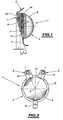
- the acetabular implant 1 illustrated in the drawingsis intended for a total hip prosthesis, of which only the proximal portion 5 of the femoral stem has been shown in FIGS. 12 and 13.
- the implant 1comprises a cup 2 adapted to receive an insert 3 freely articulated in the cup and in which can be introduced a head ( Figures 12 and 13) attached to the end of the neck of the proximal portion 5.
- the cup 2consists of a hemispherical portion 6 delimited by an equatorial plane P (FIG. 1) extended by a cylindrical portion 7 to which two iliac "expansions" 8 are attached. Next to these there is an obturator 9 formed by a hook is attached to the lower opening edge of the hemispherical portion 6 of the cup 2, in a position diametrically opposed to a location in the middle of an interval between the expansions 8.
- the cylindrical portion 7extends beyond the equatorial plane P, on a portion of the circumference of the opening edge of the cup 6, namely substantially a half circumference. More specifically, the cylindrical portion 7 extends in fact on an angular sector substantially greater than half a circumference.
- FIG. 1shows that this part 7 is delimited by a plane R inclined on the equatorial plane P, and which extends beyond the cylindrical part 7 by a truncated edge 11 of the hemispherical part 6, this truncated edge 11 is lying in the same inclined plane R.
- a a sort of truncation of the hemispherical portion 6extending from the intersection I between the inclined plane R and the equatorial plane P, to the lower edge of the cup 2 and to the shutter 9.
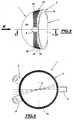
- the cylindrical portion 7has, in the radial direction, a width I appropriate to the anatomy of the acetabulum, and the plane R delimits with the equatorial plane P an angle A of about 15 degrees, whose vertex is the intersection I.
- the inclined plane Rintersects the equatorial plane P between the center O of the hemispherical part 6 and its edge adjacent to the obturator 9.
- the outer edge of the cylindrical portion 7is truncated so as to define a chamfer 12 extending parallel to the equatorial plane P and on which the iliac expansions 8 are fixed.
- Each iliac expansion 8is adaptable to the individual bone surface. It has a rectilinear end 13 attached to the edge of the cup 2, extended by a curved portion 14 whose curvature is adapted to the acetabular eyebrow 15 of an acetabular cavity (FIG. 12), a rectilinear portion 16 and then a second curved portion 17 (FIG. Figures 9 to 11) extending said curved portion 16; finally each expansion 8 terminates in a final rectilinear portion 18 in which is arranged a hole 19, preferably of oblong shape, for the passage of a possible bone anchoring screw 21 ( Figure 12).
- the final rectilinear part 18is advantageously inclined by approximately 45 degrees on the initial rectilinear part 13, while the intermediate rectilinear part 16 can be inclined by about 15 degrees on the perpendicular to the part 13.
- the oblong hole 19is advantageously provided with a countersink 22 around its periphery, allowing a polyorientation of the anchoring screw 21.
- a macrostructure 24 with reliefs 28is machined on a portion of the outer surface of the cup 2. This portion covered by the macrostructure 24 is defined substantially by the opening edge 10 of the cup 2 and a spherical cap 25 forming the bottom of the cup 2. This macrostructure 24 and the cap 25 are coated with a layer of calcium hydroxyapatite contributing, with the macrostructure 24, bone regrowth and osseointegration.
- the macrostructure 24is separated from the free edge 10 of the cup 2 by a smooth strip 26 of small width.
- the macrostructure 24delimits a set of equatorial grooves 26 located in equatorial planes parallel to the plane P, and a set of meridional grooves 27 perpendicular to the equatorial grooves 26.
- the set of these grooves 26 and 27thus forms a kind of grid, delimiting , at the intersections between the grooves 26 and 27, whose cross sections have a V-shaped profile ( Figures 3 to 8), a series of reliefs 28 each having a rectangular base.
- the flanks 26a of the equatorial grooves 26may be advantageously but not limitatively inclined by an angle B of about 30 degrees on a median plane M passing through the bottom of each groove 26, whose angular opening is thus 60 degrees and whose depth can be for example about 1 mm.
- flanks 27a meridian grooves 27( Figure 7).
- the edges forming the bottom of the equatorial grooves 26may be spaced apart by an interval e of about 2 mm (FIGS. 6 and 8), the number of these equatorial grooves 26 varying with the cup size 2.
- the meridian grooves 27are spaced two by two advantageously from approximately 6 degrees (Figure 7), so that their total number on the perimeter of the cup 2 is 60. This total number is constant regardless of the size of the cup.
- FIGS. 3 and 7show that each of the reliefs 28 has transverse and longitudinal profiles whose transverse flanks 28a delimit equatorial grooves 26, whereas their longitudinal flanks 28b delimit meridian grooves 27. All these flanks are connected to a flat 28c.
- the cup 2, uncementedcan be made for example of stainless steel according to ISO 53 32-1, coated with calcium hydroxyapatite (HAC).
- HACcalcium hydroxyapatite
- acetabular implant 1which has just been described is carried out as shown in FIG. 12: its dimensions are chosen so that the diameter of the cup 2 is slightly greater than the diameter of the natural acetabulum in which it must be implanted by the effect of "press fit” ie by impaction.
- expansions iliacs 8are placed in place by overlapping the acetabular eyebrow 15 while the shutter 9 is introduced into the obturator hole 20.
- the screws 21are implanted through the holes 19 in the appropriate orientation to find the best bone anchoring, these screws 21 may be of either the spongy bone or cortical type.
- the stability of the implant in the medium and long termis obtained by the osteoconduction induced by the coating of calcium hydroxyapatite, and by the osseointegration at the heart of the macrostructure 24 as well as possibly by the action of the iliac expansions 8 and shutter 9.
- the presence of the smooth strip 30prevents the equatorial plane P from being indented by the edge of the macrostructure 24.
- the numerical values mentioned above, although not limiting,have proved to the tests as providing the most advantageous results in terms of terms of improving the effectiveness of primary and secondary fixation of the implant in the long term.
- the fact of limiting the total number of meridional grooves 28 to 60 irrespective of the size of the acetabular implantmakes it possible for large sizes to produce large checkerboards with important reliefs 28 and which promote attachment to the wall. bone.
- the macrostructure 24is advantageously machined on the cup 2 and not reported, which has proved more effective in terms of osseointegration.
- the geometry of the cup 2, hemispherical surmounted by a cylindrical portion 7, with truncation at 15 degrees by the plane R,allows excellent angular deflection into the limit positions avoiding the risk of dislocation in these extreme positions, while also respecting the anatomy of the acetabular cavity.
- the geometry of the iliac expansions 8ensures optimal contact with the bone surface, thanks in particular to the folding of these expansions at their curved portion 14.
- the inventionis not limited to the embodiments described and may include many variants.
- the dimensions and the geometry of the reliefs 28 defined by the macrostructure 24could differ substantially from the example described, as well as the inclination for example of the plane R on the equatorial plane P.
Landscapes
- Health & Medical Sciences (AREA)
- Orthopedic Medicine & Surgery (AREA)
- Cardiology (AREA)
- Oral & Maxillofacial Surgery (AREA)
- Transplantation (AREA)
- Engineering & Computer Science (AREA)
- Biomedical Technology (AREA)
- Heart & Thoracic Surgery (AREA)
- Vascular Medicine (AREA)
- Life Sciences & Earth Sciences (AREA)
- Animal Behavior & Ethology (AREA)
- General Health & Medical Sciences (AREA)
- Public Health (AREA)
- Veterinary Medicine (AREA)
- Prostheses (AREA)
- Materials For Medical Uses (AREA)
Abstract
Description
Translated fromFrenchLa présente invention a pour objet un implant acétabulaire pour prothèse de hanche, du type comprenant une cupule adaptée pour recevoir un insert librement articulé dans la cupule, équipée d'expansions iliaques et d'une obturatrice pour fixation osseuse.The present invention relates to an acetabular implant for hip prosthesis, of the type comprising a cup adapted to receive an insert freely articulated in the cup, equipped with iliac expansions and a plug for bone fixation.
Cet implant est de première intention et « de révision » c'est à dire qu'il peut être mis en place non seulement pour la première fois, mais aussi si la cavité osseuse a besoin d'être retouchée ou améliorée, en d'autres termes si la pathologie fait apparaître des défauts osseux nécessitant des greffons de moyenne importance. En d'autres termes, cet implant peut être utilisé pour une révision tant que la cavité cotyloïdienne n'est pas détruite à plus de 50%.This implant is of first intention and "revision" ie it can be set up not only for the first time, but also if the bone cavity needs to be retouched or improved, in others terms if the pathology reveals bone defects requiring grafts of medium importance. In other words, this implant can be used for revision as long as the acetabular cavity is not destroyed more than 50%.
Le brevet français 93 .12.097 (2.710.836) décrit un implant acétabulaire de ce type pour prothèse totale de hanche, dans lequel la cupule a une forme sphérique, géométrie qui est généralement utilisée pour de tels implants. Toutefois une telle configuration n'est pas particulièrement bien adaptée à l'anatomie de la cavité acétabulaire d'une hanche, dont la paroi supérieure s'avance d'avantage que la paroi inférieure. Il en résulte une tenue mécanique qui peut laisser à désirer.French Patent 93 12 097 (2,710,836) discloses an acetabular implant of this type for total hip prosthesis, in which the cup has a spherical shape, which geometry is generally used for such implants. However, such a configuration is not particularly well suited to the anatomy of the acetabular cavity of a hip, whose upper wall advances more than the lower wall. This results in a mechanical strength that can leave something to be desired.
En outre dans les implants connus, les pattes iliaques comportent généralement une partie rectiligne directement raccordée au bord d'ouverture de la cupule. Il en résulte un manque d'adaptation à l'anatomie à cet endroit, en particulier au sourcil cotyloïdien, susceptible d'affecter le bon ancrage de la prothèse.In addition, in known implants, the iliac tabs generally comprise a rectilinear part directly connected to the opening edge of the cup. This results in a lack of adaptation to the anatomy at this location, in particular the cotyloid eyebrow, likely to affect the proper anchoring of the prosthesis.
De nombreux implants connus comportent une cupule à surface lisse en contact avec la paroi du cotyle, parfois équipée de pointes d'ancrage, de sorte que leur tenue mécanique peut s'en trouver à la longue compromise. Pour remédier à ces insuffisances on a proposé par exemple de perforer la paroi du cotyle (brevet USA 3.740.769, brevet allemand 32.05.526). Toutefois l'expérience a montré que ces aménagements ne donnent pas entière satisfaction.Many known implants have a cup with a smooth surface in contact with the wall of the acetabulum, sometimes equipped with anchoring points, so that their mechanical strength may be compromised in the long run. To remedy these shortcomings it has been proposed, for example, to perforate the wall of the acetabulum (US Pat. No. 3,740,769, German Patent No. 32.05.526). However experience has shown that these developments are not entirely satisfactory.
L'invention a donc pour but de réaliser un implant acétabulaire agencé de manière à lui assurer une excellente fixation per et post opératoire, aussi bien à moyen qu'à long terme.The object of the invention is therefore to provide an acetabular implant arranged so as to provide it with excellent per and postoperative fixation, both in the medium and long term.
On a déjà proposé dans FR-A-2 770 769, de prolonger la partie équatoriale d'une cupule hémisphérique recevant un insert, par un prolongement cylindrique dont une partie est tronquée et qui s'étend sur la quasi-totalité de la périphérie équatoriale de la cupule sphérique, dans le but, grâce à la présence de stries et de fentes situées dans cette zone prolongée, d'implanter et de fixer la cupule sans l'aide de vis. Une telle réalisation peut cependant se trouver exposée à des efforts importants en cas de mouvements extrêmes du composant fémoral de la prothèse.It has already been proposed in FR-A-2,770,769 to extend the equatorial portion of a hemispherical cup receiving an insert, by a cylindrical extension of which a portion is truncated and which extends over almost the entire equatorial periphery. of the spherical cup, for the purpose, by the presence of streaks and slots in this extended area, to implant and fix the cup without the help of screws. Such an embodiment may, however, be exposed to considerable effort in the event of extreme movements of the femoral component of the prosthesis.
L'invention se propose également de résoudre ces inconvénients et a pour objet un implant acétabulaire pour prothèse de hanche, comprenant une cupule adaptée pour recevoir un insert librement articulé dans la cupule, ladite cupule étant constituée d'une partie hémisphérique prolongée par une partie cylindrique, caractérisé en ce que la partie cylindrique s'étend sur sensiblement une demi-circonférence d'un bord équatorial de la partie hémisphérique, et est délimitée par un plan incliné sur le plan équatorial de la partie hémisphérique, ce plan incliné se prolongeant au-delà de la partie cylindrique par un bord tronqué de la partie hémisphérique situé dans le même plan incliné, ladite partie cylindrique étant équipée d'expansions iliaques, et ladite partie hémisphérique étant équipée, sur ledit bord tronqué, d'une expansion obturatrice d'ancrage osseux.The invention also proposes to solve these drawbacks and relates to an acetabular implant for hip prosthesis, comprising a cup adapted to receive an insert freely articulated in the cup, said cup being constituted by a hemispherical portion extended by a cylindrical portion , characterized in that the cylindrical portion extends over substantially one half-circumference of an equatorial edge of the hemispherical portion, and is delimited by a plane inclined to the equatorial plane of the hemispherical portion, said inclined plane extending beyond the cylindrical portion by a truncated edge of the hemispherical portion located in the same inclined plane, said cylindrical portion being equipped with iliac expansions, and said hemispherical portion being equipped on said truncated edge with an anchoring closure expansion bony.
Ainsi la partie cylindrique, dont la largeur et l'étendue angulaire sont convenablement déterminées, prolonge la cupule dans la zone des expansions iliaques, c'est à dire dans la partie supérieure de la cavité cotyloïdienne. Cette partie cylindrique est donc en contact avec la paroi osseuse jusqu'au bord de la cavité acétabulaire, avec laquelle elle assure corrélativement un meilleur contact qu'une cupule simplement hémisphérique. En d'autres termes, la partie supérieure de l'implant recouvre étroitement la paroi osseuse ce qui diminue considérablement le risque de luxation dans les positions angulaires limites de la tige fémorale associée et de l'insert articulé dans la cupule.Thus the cylindrical part, whose width and angular extent are suitably determined, extends the cup in the zone of the iliac expansions, that is to say in the upper part of the acetabulum. This cylindrical portion is in contact with the bone wall to the edge of the acetabular cavity, with which it correlatively ensures a better contact than a simply hemispherical cup. In other words, the upper part of the implant closely covers the bone wall, which considerably reduces the risk of dislocation in the limited angular positions of the associated femoral stem and the articulated insert in the cup.
L'avantage de la troncature de la partie sphérique réalisée dans la zone inférieure de l'implant réside dans le fait qu'elle empêche, dans la position extrême de l'insert en flexion-rotation interne ou en extension-rotation externe, la sortie de celui-ci à l'extérieur de la cupule par effet de came. Le col de la tige fémorale ne peut plus en effet venir en butée sur le bord inférieur d'ouverture de la cupule et risquer alors d'entraîner l'éjection de l'insert.The advantage of the truncation of the spherical portion made in the lower zone of the implant lies in the fact that it prevents, in the extreme position of the insert in internal flexion-rotation or in external extension-rotation, the exit of it outside the cup by camming. The collar of the femoral stem can no longer come into abutment on the lower edge of opening of the cup and then risk causing the ejection of the insert.
Dans la position extrême en flexion, le col de la tige fémorale ne risque pas de venir en butée contre la partie cylindrique de la cupule, dont la largeur est convenablement choisie à cet effet.In the extreme position in flexion, the neck of the femoral stem is not likely to abut against the cylindrical portion of the cup, the width of which is suitably chosen for this purpose.
En définitive, cette géométrie de l'implant acétabulaire réduit très considérablement le risque de luxation dans les deux positions extrêmes opposées de l'insert et de la tige fémorale associée, tout en favorisant un excellent débattement angulaire. De plus, la géométrie de la cupule lui permet de respecter au maximum l'anatomie de la cavité acétabulaire.Ultimately, this geometry of the acetabular implant greatly reduces the risk of dislocation in the two opposite extreme positions of the insert and the associated femoral stem, while promoting excellent angular movement. In addition, the geometry of the cup allows it to fully respect the anatomy of the acetabular cavity.
Suivant une autre caractéristique de l'invention, les expansions iliaques comportent une extrémité rectiligne rapportée au bord de la cupule, prolongée par une partie courbée dont la courbure est adaptée au sourcil cotyloïdien d'une cavité acétabulaire, une partie rectiligne puis une partie incurvée prolongeant ladite partie courbée ; enfin une partie rectiligne finale raccordée à la partie incurvée et dans laquelle est agencé un trou de passage d'une vis d'ancrage osseux.According to another characteristic of the invention, the iliac expansions comprise a rectilinear end attached to the edge of the cup, extended by a curved portion whose curvature is adapted to the acetabular eyebrow of an acetabular cavity, a rectilinear portion and then a curved portion extending said curved portion; finally a final rectilinear part connected to the curved portion and in which is arranged a passage hole of a bone anchoring screw.
Avantageusement les deux parties rectilignes extrêmes délimitent entre elles un angle d'environ 45 degrés de préférence.Advantageously, the two extreme rectilinear parts define between them an angle of approximately 45 degrees of preference.
Cette géométrie permet aux expansions iliaques de s'adapter étroitement à l'anatomie osseuse à cet endroit, près du bord de la cavité acétabulaire, au besoin lui-même modelé.This geometry allows the iliac expansions to closely adapt to the bone anatomy at this location, near the edge of the acetabular cavity, if necessary modeled itself.
Suivant une autre particularité de l'invention, une macrostructure à reliefs favorisant un ancrage primaire et une ostéointégration est usinée sur la surface externe de la cupule comprise sensiblement entre ledit plan incliné délimitant l'ouverture de la cupule et une calotte sphérique délimitant le fond de la cupule, et cette macrostructure ainsi que la calotte sont revêtus d'hydroxyapatite de calcium.According to another feature of the invention, a relief macrostructure promoting primary anchoring and osseointegration is machined on the outer surface of the cup substantially between said inclined plane defining the opening of the cup and a spherical cap defining the bottom of the cup. the cup, and this macrostructure and the cap are coated with calcium hydroxyapatite.
Cette macrostructure, dont la géométrie est convenablement choisie pour n'être ni trop lisse ni trop agressive, permet un meilleur ancrage primaire et à long terme de la cupule, par repousse osseuse en assurant à l'implant sa stabilité à long terme.This macrostructure, whose geometry is appropriately chosen to be neither too smooth nor too aggressive, allows a better primary and long-term anchorage of the cup, by bone regrowth by ensuring the implant its long-term stability.
D'autres particularités et avantages de l'invention apparaîtront au cours de la description qui va suivre, faite en référence aux dessins annexés qui en illustrent une forme de réalisation à titre d'exemple non limitatif.
- La figure 1 est une vue en élévation latérale sensiblement à l'échelle, d'une forme de réalisation de l'implant acétabulaire selon l'invention, vu dans un plan sagittal.
- La figure 2 est une vue en élévation dans un plan frontal de l'implant de la figure 1.
- La figure 3 est une vue en élévation à échelle agrandie par rapport aux figures 1 et 2, d'une forme de réalisation industrielle de l'implant conforme à l'invention.
- La figure 4 est une vue en élévation suivant la flèche K de la figure 3.
- La figure 5 est une vue en élévation de l'implant acétabulaire prise suivant la direction de la flèche K de la figure 3.
- La figure 6 est une vue en coupe suivant 6-6 de la figure 3.
- La figure 7 est une vue en perspective à échelle agrandie d'un détail de la surface externe à macrostructure de l'implant des figures 3 à 6.
- La figure 8 est une vue en coupe partielle à échelle agrandie de rainures équatoriales visibles aux figures 3 à 6.
- La figure 9 est une vue en élévation à échelle agrandie d'un mode de réalisation d'une expansion iliaque rapportée à un implant selon l'une des figures 1 à 7.
- La figure 10 est une vue en élévation latérale de l'expansion iliaque de la figure 9.
- La figure 11 est une vue en perspective de l'expansion iliaque des figures 9 et 10.
- La figure 12 est une vue en élévation dans un plan frontal de l'implant selon l'invention ainsi que de l'extrémité supérieure de la tige fémorale associée, représentée en abduction-extension.
- La figure 13 est une vue en élévation analogue à la figure 12, représentant la position extrême pouvant être prise par la tige fémorale par rapport à l'implant acétabulaire en adduction-flexion.
- Figure 1 is a substantially scale side elevational view of an embodiment of the acetabular implant according to the invention, seen in a sagittal plane.
- Figure 2 is an elevational view in a frontal plane of the implant of Figure 1.
- Figure 3 is an elevational view on an enlarged scale with respect to Figures 1 and 2, an industrial embodiment of the implant according to the invention.
- Figure 4 is an elevational view along the arrow K of Figure 3.
- FIG. 5 is an elevational view of the acetabular implant taken in the direction of arrow K of FIG. 3.
- Figure 6 is a sectional view along 6-6 of Figure 3.
- FIG. 7 is an enlarged perspective view of a detail of the macrostructure external surface of the implant of FIGS. 3 to 6.
- Figure 8 is an enlarged partial sectional view of equatorial grooves visible in Figures 3 to 6.
- FIG. 9 is an enlarged elevational view of an embodiment of an iliac expansion relative to an implant according to one of FIGS. 1 to 7.
- Figure 10 is a side elevational view of the iliac expansion of Figure 9.
- Figure 11 is a perspective view of the iliac expansion of Figures 9 and 10.
- Figure 12 is an elevational view in a frontal plane of the implant according to the invention as well as the upper end of the associated femoral stem, shown in abduction-extension.
- Figure 13 is an elevational view similar to Figure 12, showing the extreme position that can be taken by the femoral stem relative to the acetabular adduction-flexion implant.
L'implant acétabulaire 1 illustré aux dessins est destiné à une prothèse totale de hanche, dont seule la partie proximale 5 de la tige fémorale a été représentée aux figures 12 et 13.The
L'implant 1 comprend une cupule 2 adaptée pour recevoir un insert 3 librement articulé dans la cupule et dans lequel peut être introduite une tête (figures 12 et 13) rapportée à l'extrémité du col de la partie proximale 5.The
La cupule 2 est constituée d'une partie hémisphérique 6 délimitée par un plan équatorial P (figure 1) prolongée par une partie cylindrique 7 à laquelle sont fixées deux « expansions » iliaques 8. En regard de celles-ci une obturatrice 9, formée par un crochet est rapportée au bord inférieur d'ouverture de la partie hémisphérique 6 de la cupule 2, en une position diamétralement opposée à un emplacement situé au milieu d'un intervalle entre les expansions 8.The
La partie cylindrique 7 s'étend au delà du plan équatorial P, sur une partie de la circonférence du bord d'ouverture de la cupule 6, à savoir sensiblement sur une demi circonférence. De manière plus précise, la partie cylindrique 7 s'étend en fait sur un secteur angulaire sensiblement supérieur à une demi circonférence. On voit à la figure 1 que cette partie 7 est délimitée par un plan R incliné sur le plan équatorial P, et qui se prolonge au delà de la partie cylindrique 7 par un bord tronqué 11 de la partie hémisphérique 6, ce bord tronqué 11 se situant dans le même plan incliné R. Ainsi est réalisée une sorte de troncature de la partie hémisphérique 6 s'étendant depuis l'intersection I entre le plan incliné R et le plan équatorial P, jusqu'au bord inférieur de la cupule 2 et à l'obturatrice 9.The
La partie cylindrique 7 possède, dans la direction radiale, une largeur I appropriée à l'anatomie du cotyle, et le plan R délimite avec le plan équatorial P un angle A d'environ 15 degrés, dont le sommet est l'intersection I. Le plan incliné R intersecte le plan équatorial P entre le centre O de la partie hémisphérique 6 et son bord attenant à l'obturatrice 9.The
Le bord extérieur de la partie cylindrique 7 est tronqué de manière à délimiter un chanfrein 12 s'étendant parallèlement au plan équatorial P et sur lequel viennent se fixer les expansions iliaques 8.The outer edge of the
Chaque expansion iliaque 8 est adaptable à la surface ossseuse individuelle. Elle comporte une extrémité rectiligne 13 rapportée au bord de la cupule 2, prolongée par une partie courbée 14 dont la courbure est adaptée au sourcil cotyloïdien 15 d'une cavité acétabulaire (figure 12), une partie rectiligne 16 puis une seconde partie incurvée 17 (figures 9 à 11) prolongeant ladite partie courbée 16 ; enfin chaque expansion 8 se termine par une partie rectiligne finale 18 dans laquelle est agencé un trou 19, avantageusement de forme oblongue, pour le passage d'une vis éventuelle 21 d'ancrage osseux (figure 12).Each
La partie rectiligne finale 18 est avantageusement inclinée d'environ 45 degrés sur la partie rectiligne initiale 13, tandis que la partie rectiligne intermédiaire 16 peut être inclinée de 15 degrés environ sur la perpendiculaire à la partie 13. Le trou oblong 19 est avantageusement muni d'un lamage 22 sur son pourtour, permettant une polyorientation de la vis d'ancrage 21.The final
La courbure de la partie incurvée 14, adaptée au passage du sourcil cotyloïdien, et l'angulation de la partie rectiligne 18 à 45 degrés par rapport à la patte 13 garantissent la proximité entre les expansions 8 et la surface osseuse. Ainsi, ces deux particularités assurent un excellent respect de l'anatomie locale par les expansions iliaques 8.The curvature of the
Une macrostructure 24 à reliefs 28 est usinée sur une partie de la surface externe de la cupule 2. Cette partie recouverte par la macrostructure 24 est délimitée sensiblement par le bord 10 d'ouverture de la cupule 2 et une calotte sphérique 25 formant le fond de la cupule 2. Cette macrostructure 24 ainsi que la calotte 25 sont revêtus d'une couche d'hydroxyapatite de calcium contribuant, avec la macrostructure 24, à la repousse osseuse et à l'ostéointégration.A
La macrostructure 24 est séparée du bord libre 10 de la cupule 2 par une bande lisse 26 de faible largeur. La macrostructure 24 délimite un ensemble de rainures équatoriales 26 situées dans des plans équatoriaux parallèles au plan P, et un ensemble de rainures méridiennes 27 perpendiculaires aux rainures équatoriales 26. L'ensemble de ces rainures 26 et 27 forme donc une sorte de quadrillage, délimitant, aux intersections entre les rainures 26 et 27, dont les sections transversales ont un profil en V (figures 3 à 8), une série de reliefs 28 ayant chacun une base rectangulaire.The
Les flancs 26a des rainures équatoriales 26 peuvent être avantageusement mais non limitativement inclinés d'un angle B de 30 degrés environ sur un plan médian M passant par le fond de chaque rainure 26, dont l'ouverture angulaire est ainsi de 60 degrés et dont la profondeur peut être par exemple de 1 mm environ.The
Il en est de même pour les flancs 27a des rainures méridiennes 27 (figure 7). Par ailleurs, également à titre d'exemple numérique non limitatif, les arêtes formant le fond des rainures équatoriales 26 peuvent être espacées d'un intervallee de 2mm environ (figures 6 et 8), le nombre de ces rainures équatoriales 26 variant avec la taille de la cupule 2 .It is the same for the
Enfin les rainures méridiennes 27 sont espacées deux à deux angulairement avantageusement de 6 degrés environ (figure 7), de sorte que leur nombre total sur le pourtour de la cupule 2 est de 60. Ce nombre total est constant quelle que soit la taille de la cupule.Finally, the
On voit aux figures 3 et 7 que chacun des reliefs 28 présente des profils transversal et longitudinal, dont les flancs transversaux 28a délimitent des rainures équatoriales 26, tandis que leurs flancs longitudinaux 28b délimitent des rainures méridiennes 27. Tous ces flancs sont raccordés à un plat 28c.FIGS. 3 and 7 show that each of the
La cupule 2, non cimentée, peut être réalisée par exemple en acier inoxydable selon la norme ISO 53 32-1, recouverte d'hydroxyapatite de calcium (HAC).The
La mise en place de l'implant acétabulaire 1 qui vient d'être décrit s'effectue comme représenté à la figure 12: ses dimensions sont choisies de manière que le diamètre de la cupule 2 soit légèrement supérieur au diamètre du cotyle naturel dans lequel elle doit être implantée par effet de « press fit » c'est à dire par impaction. En même temps, les expansions iliaques 8 se mettent en place en chevauchant le sourcil cotyloïdien 15 tandis que l'obturatrice 9 vient s'introduire dans le trou obturateur 20. Si nécessaire les vis 21 sont implantées à travers les trous 19 suivant l'orientation appropriée afin de trouver le meilleur ancrage osseux, ces vis 21 pouvant être du type soit à os spongieux soit à corticale.The introduction of the
La stabilité immédiate, per et post opératoire de la cupule 2, est assurée par la combinaison des éléments suivants :
- l'impaction en « press fit » de l'implant 1 dans le cotyle naturel,
- la présence de la macrostructure 24 revêtue d'hydroxyapatite,
- le vissage (éventuel) des expansions iliaques par les vis 21,
- la mise en position et le maintien de la cupule 2
par l'obturatrice 9.
- the impaction in "press fit" of the
implant 1 in the natural acetabulum, - the presence of the
macrostructure 24 coated with hydroxyapatite, - the screwing (if any) of the iliac expansions by the
screws 21, - positioning and maintaining the
cup 2 by theshutter 9.
La stabilité de l'implant à moyen et long terme est obtenue par l'ostéoconduction induite par le revêtement d'hydroxyapatite de calcium, et par l'ostéointégration au coeur de la macrostructure 24 ainsi qu'éventuellement par l'action des expansions iliaques 8 et de l'obturatrice 9.The stability of the implant in the medium and long term is obtained by the osteoconduction induced by the coating of calcium hydroxyapatite, and by the osseointegration at the heart of the
Ainsi tous ces éléments garantissent une excellente fixation primaire et secondaire de l'implant 1, et par conséquent une durée de vie optimale.Thus all these elements ensure excellent primary and secondary fixation of the
Les expansions iliaques 8 adaptables à l'os, dont elles épousent la surface osseuse, et l'obturatrice 9 permettent de pincer la branche ischio-pubienne.The
La présence de la bande lisse 30 évite de denteler le plan équatorial P par le bord de la macrostructure 24. Par ailleurs, les valeurs numériques mentionnées ci-dessus, quoique non limitatives, se sont révélées aux essais comme fournissant les résultats les plus avantageux en termes d'amélioration de l'efficacité de la fixation primaire et secondaire à long terme de l'implant. Ainsi le fait de limiter le nombre total de rainures méridiennes 28 à 60 quelle que soit la taille de l'implant acétabulaire, permet de réaliser pour les grandes tailles, de grands damiers avec des reliefs importants 28 et qui favorisent l'accrochage à la paroi osseuse. La macrostructure 24 est avantageusement usinée sur la cupule 2 et non rapportée, ce qui s'est révélé plus efficace en termes d'ostéointégration.The presence of the
Par ailleurs il est avéré inutile d'agencer une macrostructure 24 sur la calotte sphérique 25 qui vient en contact avec le fond du cotyle naturel. En effet les contraintes subies à ce niveau sont faibles, alors qu'elles sont maximales dans la zone supérieure du cotyle, les efforts exercés diminuant dans les zones postérieure et antérieure de la cavité.Moreover, it has proved useless to arrange a
En résumé, la géométrie de la cupule 2, hémisphérique surmontée d'une partie cylindrique 7, avec troncature à 15 degrés par le plan R, permet un excellent débattement angulaire jusque dans les positions limites en évitant des risques de luxation dans ces positions extrêmes, tout en respectant en outre au maximum l'anatomie de la cavité acétabulaire.In summary, the geometry of the
La géométrie des expansions iliaques 8 leur assure un contact optimal avec la surface osseuse, grâce en particulier au pliage de ces expansions au niveau de leur partie incurvée 14.The geometry of the
L'association de la macrostructure 24 dont la géométrie est bien définie comme exposée ci-dessus, et d'un revêtement d'hydroxyapatite de calcium, assure, d'une part une bonne pénétration des trabécules osseux au sein de la macrostructure 24, c'est à dire favorise une bonne ostéointégration, et d'autre part garantit la stabilité de l'implant acétibulaire dans le temps.The combination of the
L'invention n'est pas limitée aux modes de réalisation décrits et peut comporter de nombreuses variantes d'exécution. Ainsi les dimensions et la géométrie des reliefs 28 définis par la macrostructure 24 pourraient différer sensiblement de l'exemple décrit, de même que l'inclinaison par exemple du plan R sur le plan équatorial P.The invention is not limited to the embodiments described and may include many variants. Thus the dimensions and the geometry of the
Claims (9)
- Acetabular implant (1) for a hip prosthesis, comprising a cup (2) arranged to receive an insert (3) freely articulated in the cup, said cup being composed of a hemispherical portion (6) extended by a cylindrical portion (7),characterised in that the cylindrical portion (7) extends over substantially half a circumference of an equatorial edge of the hemispherical portion (6) and is delimited by a plane (R) inclined with respect to the equatorial plane (P) of the hemispherical portion (6), that inclined plane being extended beyond the cylindrical portion (7) by means of a truncated edge (11) of the hemispherical portion (6), which edge (11) is located in the same inclined plane (R), said cylindrical portion (7) being provided with iliac extensions (8), and said hemispherical portion (6) being provided, on said truncated edge, with an obturator extension for bone anchoring.
- Implant according to claim 1,characterised in that said inclined plane (R) delimits, together with the equatorial plane (P) of the cup (2), an angle (A) of about 15 degrees, which intersects the equatorial plane between the centre (O) of the hemispherical portion (6) and its edge adjoining the obturator element (9), the cylindrical portion (7) having a width (I) appropriate for that purpose.
- Implant according to one of claims 1 and 2,characterised in that the iliac extensions (8) comprise a rectilinear end (13) attached to the edge of the cup (2) and extended by a curved portion (14) whose curvature is matched to the cotyloid brow (15) of an acetabular cavity, a rectilinear portion (16) and then an incurvate portion (17) extending said curved portion, and finally a final rectilinear portion (18) which is attached to the incurvate portion and in which there is provided a through-hole (19) for a screw (21) for bone anchoring.
- Implant according to claim 3,characterised in that the final rectilinear portion (18) is inclined about 45 degrees with respect to said rectilinear end (13), the hole (19) is oblong and comprises a countersink (22) allowing polyorientation of the screw (21) for bone anchoring.
- Implant according to one of claims 1 to 4,characterised in that a macrostructure (24) having reliefs (28) promoting osseointegration is machined on the external surface of the cup (2) included substantially between said inclined plane (R) delimiting the opening of the cup (2) and a spherical cap (25) delimiting the bottom of the cup, and that macrostructure and also the cap are coated with calcium hydroxyapatite.
- Implant according to claim 5,characterised in that a smooth band (30) is reserved between the edge of the opening (10) of the cup (2) and the start of the macrostructure (24) having reliefs (28).
- Implant according to claims 5 and 8,characterised in that the macrostructure (24) delimits a set of equatorial grooves (26) located in parallel equatorial planes and a set of meridional grooves (27) perpendicular to the equatorial grooves, and those different equatorial and meridional grooves have a V-shaped transverse section the sides (26a) of which are inclined about 30 degrees with respect to a medial plane (M) passing through the bottom of the groove (26, 27), whilst the depth of those equatorial and meridional grooves is about 1 mm.
- Implant according to claim 7,characterised in that the apices (30) forming the bottom of the equatorial grooves (26) are spaced about 2 mm apart, and the number of those grooves varies according to the size of the cup (2).
- Implant according to claim 7 or 8,characterised in that the meridional grooves (127) are spaced apart from one to the next at angles of about 6 degrees so that their total number over the circumference of the cup (2) is 60, that total number being constant whatever the size of the cup.
Applications Claiming Priority (3)
| Application Number | Priority Date | Filing Date | Title |
|---|---|---|---|
| FR9912085 | 1999-09-28 | ||
| FR9912085AFR2798841B1 (en) | 1999-09-28 | 1999-09-28 | ACETABULAR IMPLANT FOR HIP PROSTHESIS |
| PCT/FR2000/002657WO2001024740A1 (en) | 1999-09-28 | 2000-09-26 | Acetabular implant for hip prosthesis |
Publications (2)
| Publication Number | Publication Date |
|---|---|
| EP1216011A1 EP1216011A1 (en) | 2002-06-26 |
| EP1216011B1true EP1216011B1 (en) | 2006-05-24 |
Family
ID=9550321
Family Applications (1)
| Application Number | Title | Priority Date | Filing Date |
|---|---|---|---|
| EP00964373AExpired - LifetimeEP1216011B1 (en) | 1999-09-28 | 2000-09-26 | Acetabular implant for hip prosthesis |
Country Status (7)
| Country | Link |
|---|---|
| US (1) | US6620200B1 (en) |
| EP (1) | EP1216011B1 (en) |
| JP (1) | JP2003510163A (en) |
| AT (1) | ATE326922T1 (en) |
| DE (1) | DE60028220T2 (en) |
| FR (1) | FR2798841B1 (en) |
| WO (1) | WO2001024740A1 (en) |
Families Citing this family (35)
| Publication number | Priority date | Publication date | Assignee | Title |
|---|---|---|---|---|
| US8123814B2 (en) | 2001-02-23 | 2012-02-28 | Biomet Manufacturing Corp. | Method and appartus for acetabular reconstruction |
| US7597715B2 (en) | 2005-04-21 | 2009-10-06 | Biomet Manufacturing Corp. | Method and apparatus for use of porous implants |
| US6840959B2 (en)* | 2001-07-05 | 2005-01-11 | Howmedica Ostenics Corp. | Pelvic prosthesis plus methods and tools for implantation |
| US6908486B2 (en)* | 2002-01-25 | 2005-06-21 | Mayo Foundation For Medical Education And Research | Modular acetabular anti-protrusio cage and porous ingrowth cup combination |
| CA2400955A1 (en)* | 2002-08-22 | 2004-02-22 | Roger Bacon | Expandable prosthetic cotyle |
| FR2858760B1 (en)* | 2003-08-14 | 2006-05-05 | Philippe Lapresle | CUPIL FOR COTYLOID IMPLANT OF TOTAL HIP PROSTHESIS, COTYLOID IMPLANT AND TOTAL HIP PROSTHESIS COMPRISING IT |
| GB2406056B (en)* | 2003-09-17 | 2007-07-11 | Corin Ltd | Prosthetic cup |
| GB0408793D0 (en) | 2004-04-20 | 2004-05-26 | Finsbury Dev Ltd | Tool |
| GB0408791D0 (en)* | 2004-04-20 | 2004-05-26 | Finsbury Dev Ltd | Prosthesis |
| US7918896B2 (en)* | 2004-09-15 | 2011-04-05 | Wright Medical Technology, Inc. | Unitary acetabular cup prosthesis with extension for deficient acetabulum |
| FR2879916A1 (en)* | 2004-12-29 | 2006-06-30 | Patrice Gestraud | Hip prosthesis for human being, has spacer to integrate eyelet with acetabulum, and fixation screw cooperating with eyelet`s opening and having stem, threading for step and another threading formed between shoulder head and determined point |
| FR2883722B1 (en)* | 2005-03-31 | 2007-06-22 | Evolutis Sa | COTYLOID IMPLANT |
| US20060226570A1 (en)* | 2005-04-12 | 2006-10-12 | Zimmer Technology, Inc. | Method for making a metal-backed acetabular implant |
| US8066778B2 (en) | 2005-04-21 | 2011-11-29 | Biomet Manufacturing Corp. | Porous metal cup with cobalt bearing surface |
| US8266780B2 (en) | 2005-04-21 | 2012-09-18 | Biomet Manufacturing Corp. | Method and apparatus for use of porous implants |
| US8021432B2 (en) | 2005-12-05 | 2011-09-20 | Biomet Manufacturing Corp. | Apparatus for use of porous implants |
| US8292967B2 (en) | 2005-04-21 | 2012-10-23 | Biomet Manufacturing Corp. | Method and apparatus for use of porous implants |
| GB0521173D0 (en)* | 2005-10-18 | 2005-11-23 | Finsbury Dev Ltd | Tool |
| US7708783B2 (en)* | 2005-11-04 | 2010-05-04 | Zimmer Technology, Inc. | Rotating constrained liner |
| US7635447B2 (en) | 2006-02-17 | 2009-12-22 | Biomet Manufacturing Corp. | Method and apparatus for forming porous metal implants |
| US8308811B2 (en)* | 2006-04-11 | 2012-11-13 | Zimmer, Inc. | Acetabular cup conversion ring |
| US20070239283A1 (en)* | 2006-04-11 | 2007-10-11 | Berger Richard A | Acetabular cup conversion ring |
| FR2902993B1 (en)* | 2006-06-28 | 2008-09-05 | Trois S Ortho Sa | SHOULDER PROSTHESIS AND INSTRUMENT SET FOR THE IMPLANTATION OF THIS PROSTHESIS |
| DE102006062618A1 (en)* | 2006-12-29 | 2008-07-03 | Plus Orthopedics Ag | Hip joint prosthesis, particularly to place spherical joint shell for regulation, comprises metallic outer shell, inlay that is anchored in outer shell and has articulating or bearing surface for femoral condyle |
| US7980857B2 (en)* | 2007-04-06 | 2011-07-19 | Tenex Corporation | Foldable dry erase board |
| GB0804998D0 (en)* | 2008-03-18 | 2008-04-16 | Depuy Ireland Ltd | A cup component of an orthopaedic joint prosthesis |
| US8211184B2 (en)* | 2009-04-20 | 2012-07-03 | Michael D. Ries | Acetabular cup |
| GB0907036D0 (en) | 2009-04-24 | 2009-06-03 | Depuy Int Ltd | Surgical prostheses |
| US9649194B2 (en)* | 2009-07-10 | 2017-05-16 | Peter Forsell | Hip joint device |
| GB0918484D0 (en)* | 2009-10-22 | 2009-12-09 | Depuy Int Ltd | A medical implant device |
| FR3026938B1 (en)* | 2014-10-10 | 2020-11-06 | C 2 F Implants | COTYLOID IMPLANT |
| US10064730B2 (en)* | 2015-03-13 | 2018-09-04 | Patrick Birmingham | Method and device for joint replacement |
| US10537658B2 (en) | 2017-03-28 | 2020-01-21 | DePuy Synthes Products, Inc. | Orthopedic implant having a crystalline gallium-containing hydroxyapatite coating and methods for making the same |
| US10537661B2 (en) | 2017-03-28 | 2020-01-21 | DePuy Synthes Products, Inc. | Orthopedic implant having a crystalline calcium phosphate coating and methods for making the same |
| US11918475B2 (en)* | 2021-03-31 | 2024-03-05 | DePuy Synthes Products, Inc. | Modular acetabular surgical implant assembly |
Family Cites Families (13)
| Publication number | Priority date | Publication date | Assignee | Title |
|---|---|---|---|---|
| DE1806323A1 (en)* | 1968-10-31 | 1970-06-25 | Link Waldemar Fa | Hip socket for a hip prosthesis |
| US3740769A (en) | 1971-02-11 | 1973-06-26 | E Haboush | Prosthesis for hip joints |
| DE3205526A1 (en) | 1982-02-12 | 1983-09-01 | Mecron Medizinische Produkte Gmbh, 1000 Berlin | Stencil for the application of reception holes in the hip region, and a basket therefor |
| FR2634372A1 (en)* | 1988-07-20 | 1990-01-26 | Balay Bruno | Acetabular reconstruction module |
| FR2660546B1 (en)* | 1990-04-06 | 1994-06-03 | Setiey Louis | COTYLOUIDIAN RECONSTRUCTION MODULE. |
| FR2686502B1 (en)* | 1992-01-23 | 1999-04-16 | Rech Fabrication Et | NON-SEALED AND UNSCREWED CUP FOR TOTAL HIP PROSTHESIS. |
| EP0563503B1 (en)* | 1992-04-03 | 1996-12-27 | Sulzer Orthopädie AG | Outer shell for an artificial acetabular cup |
| DE59208435D1 (en)* | 1992-10-07 | 1997-06-05 | Osteo Ag | Acetabular cup support ring |
| FR2710836B1 (en) | 1993-10-06 | 1995-11-17 | Rambert Andre | Cotyloid element of total hip prosthesis, implantable without cement. |
| US5702477A (en)* | 1996-05-09 | 1997-12-30 | Osteonics Corp. | Acetabular shell with supplemental support and method |
| US5931870A (en)* | 1996-10-09 | 1999-08-03 | Smith & Nephew, Inc. | Acetabular ring prosthesis with reinforcement buttress |
| DE19731442A1 (en)* | 1997-07-22 | 1999-02-11 | Plus Endoprothetik Ag | Cup for a joint endoprosthesis |
| FR2770769B1 (en)* | 1997-11-07 | 2000-02-18 | Orthotechnique | ACETABULAR COMPONENT |
- 1999
- 1999-09-28FRFR9912085Apatent/FR2798841B1/ennot_activeExpired - Fee Related
- 2000
- 2000-09-26USUS10/089,255patent/US6620200B1/ennot_activeExpired - Lifetime
- 2000-09-26WOPCT/FR2000/002657patent/WO2001024740A1/enactiveIP Right Grant
- 2000-09-26ATAT00964373Tpatent/ATE326922T1/ennot_activeIP Right Cessation
- 2000-09-26EPEP00964373Apatent/EP1216011B1/ennot_activeExpired - Lifetime
- 2000-09-26DEDE60028220Tpatent/DE60028220T2/ennot_activeExpired - Lifetime
- 2000-09-26JPJP2001527740Apatent/JP2003510163A/enactivePending
Also Published As
| Publication number | Publication date |
|---|---|
| US6620200B1 (en) | 2003-09-16 |
| WO2001024740A1 (en) | 2001-04-12 |
| DE60028220D1 (en) | 2006-06-29 |
| JP2003510163A (en) | 2003-03-18 |
| DE60028220T2 (en) | 2007-03-08 |
| FR2798841B1 (en) | 2002-03-01 |
| FR2798841A1 (en) | 2001-03-30 |
| EP1216011A1 (en) | 2002-06-26 |
| ATE326922T1 (en) | 2006-06-15 |
Similar Documents
| Publication | Publication Date | Title |
|---|---|---|
| EP1216011B1 (en) | Acetabular implant for hip prosthesis | |
| EP1229872B1 (en) | Expansible acetabular prosthesis with double mobility | |
| EP1510190B1 (en) | Glenoid component of a shoulder prosthesis and total shoulder prosthesis comprising such a component | |
| EP2257244B1 (en) | Cotyloid element of a hip prosthesis, and total hip prosthesis comprising same | |
| FR2746631A1 (en) | SET OF ELEMENTS FOR THE CONSTITUTION OF A TOTAL PROSTHESIS OF THE HIP | |
| FR2633823A1 (en) | Bone cotyle support ring for hip prosthesis | |
| FR2725617A1 (en) | FEMALE ROD FOR HIP PROSTHESIS | |
| FR2676914A1 (en) | Anatomical femoral prosthesis | |
| WO2005011537A2 (en) | Acetabular implant and method for the production of said implant | |
| FR2786390A1 (en) | CORRECTION COTYL FOR USE IN THE TREATMENT OF HIP CONDITIONS | |
| FR2600527A1 (en) | Femoral part for hip prosthesis | |
| EP0241361B1 (en) | Hip prosthesis | |
| FR2715556A1 (en) | Reconstruction of acetabulum cavity during hip replacement | |
| CA2586800C (en) | Acetabular prosthesis to be fixed without cement | |
| FR2819172A1 (en) | Replacement acetabular cup for hip prosthesis has angled fixed lug with fastening hole and hook to engage with pelvic aperture | |
| FR2960418A1 (en) | Glenoid assembly for shoulder prosthesis, has base plate provided with part for receiving anchoring rod and articulation element, where base plate is provided with another part with fixation arrangements in coracoid process | |
| FR2683717A1 (en) | Femoral stem for total hip prosthesis | |
| FR2883723A1 (en) | Trapezo-metacarpal joint prosthesis has metacarpal cup made with external and internal sharp-edged projections to fix against trapezoid bone and insert | |
| FR2768046A1 (en) | COTYLE WITH PLUGS | |
| FR2668923A1 (en) | Cup for acetabular implantation, and hip prosthesis comprising this cup | |
| EP1068843B1 (en) | Acetabular cup for hip prosthesis | |
| WO2010031922A1 (en) | Femoral rod for a hip prosthesis | |
| FR2628967A1 (en) | Total hip prosthesis with curved femoral rod - formed with fin on its convex side engaged in groove in medullar canal near greater trochanter | |
| FR2681239A1 (en) | Shaft for total hip prosthesis | |
| FR2973221A1 (en) | U-shaped intervertebral implant for implanting between cervical vertebrae, has lower lateral branch including transverse rib coming into contact with upper lateral branch to limit connection of free ends of branches |
Legal Events
| Date | Code | Title | Description |
|---|---|---|---|
| PUAI | Public reference made under article 153(3) epc to a published international application that has entered the european phase | Free format text:ORIGINAL CODE: 0009012 | |
| 17P | Request for examination filed | Effective date:20020321 | |
| AK | Designated contracting states | Kind code of ref document:A1 Designated state(s):AT BE CH CY DE DK ES FI FR GB GR IE IT LI LU MC NL PT SE | |
| RIN1 | Information on inventor provided before grant (corrected) | Inventor name:DERHI, GUY Inventor name:DESCAMPS, LOYS Inventor name:MASELLI, ALAIN Inventor name:ZANELLO, SYLVAIN Inventor name:REMI, MARCEL Inventor name:MAESTRO, MICHEL Inventor name:PUCH, JEAN-MARC | |
| 17Q | First examination report despatched | Effective date:20040205 | |
| RIN1 | Information on inventor provided before grant (corrected) | Inventor name:ZANELLO, SYLVAIN Inventor name:MASELLI, ALAIN Inventor name:PUCH, JEAN-MARC Inventor name:MAESTRO, MICHEL Inventor name:DERHI, GUY Inventor name:DESCAMPS, LOYS Inventor name:REMI, MARCEL | |
| RAP1 | Party data changed (applicant data changed or rights of an application transferred) | Owner name:DEPUY FRANCE Owner name:MAESTRO, MICHEL Owner name:DESCAMPS, LOYS Owner name:DERHI, GUY Owner name:REMI, MARCEL Owner name:PUCH, JEAN-MARC | |
| RAP3 | Party data changed (applicant data changed or rights of an application transferred) | Owner name:DERHI, GUY Owner name:DEPUY FRANCE Owner name:REMI, MARCEL Owner name:DESCAMPS, LOYS Owner name:PUCH, JEAN-MARC Owner name:MAESTRO, MICHEL | |
| GRAP | Despatch of communication of intention to grant a patent | Free format text:ORIGINAL CODE: EPIDOSNIGR1 | |
| RIN1 | Information on inventor provided before grant (corrected) | Inventor name:DESCAMPS, LOYS Inventor name:ZANELLO, SYLVAIN Inventor name:PUCH, JEAN-MARC Inventor name:MASELLI, ALAIN Inventor name:DERHI, GUY Inventor name:REMI, MARCEL Inventor name:MAESTRO, MICHEL | |
| RAP1 | Party data changed (applicant data changed or rights of an application transferred) | Owner name:REMI, MARCEL Owner name:DEPUY (IRELAND) LIMITED Owner name:DESCAMPS, LOYS Owner name:MAESTRO, MICHEL Owner name:PUCH, JEAN-MARC Owner name:DERHI, GUY | |
| GRAS | Grant fee paid | Free format text:ORIGINAL CODE: EPIDOSNIGR3 | |
| GRAA | (expected) grant | Free format text:ORIGINAL CODE: 0009210 | |
| AK | Designated contracting states | Kind code of ref document:B1 Designated state(s):AT BE CH CY DE DK ES FI FR GB GR IE IT LI LU MC NL PT SE | |
| PG25 | Lapsed in a contracting state [announced via postgrant information from national office to epo] | Ref country code:FI Free format text:LAPSE BECAUSE OF FAILURE TO SUBMIT A TRANSLATION OF THE DESCRIPTION OR TO PAY THE FEE WITHIN THE PRESCRIBED TIME-LIMIT Effective date:20060524 Ref country code:NL Free format text:LAPSE BECAUSE OF FAILURE TO SUBMIT A TRANSLATION OF THE DESCRIPTION OR TO PAY THE FEE WITHIN THE PRESCRIBED TIME-LIMIT Effective date:20060524 Ref country code:AT Free format text:LAPSE BECAUSE OF FAILURE TO SUBMIT A TRANSLATION OF THE DESCRIPTION OR TO PAY THE FEE WITHIN THE PRESCRIBED TIME-LIMIT Effective date:20060524 | |
| REG | Reference to a national code | Ref country code:GB Ref legal event code:FG4D Free format text:NOT ENGLISH | |
| REG | Reference to a national code | Ref country code:CH Ref legal event code:EP | |
| REG | Reference to a national code | Ref country code:IE Ref legal event code:FG4D Free format text:LANGUAGE OF EP DOCUMENT: FRENCH | |
| REF | Corresponds to: | Ref document number:60028220 Country of ref document:DE Date of ref document:20060629 Kind code of ref document:P | |
| PG25 | Lapsed in a contracting state [announced via postgrant information from national office to epo] | Ref country code:DK Free format text:LAPSE BECAUSE OF FAILURE TO SUBMIT A TRANSLATION OF THE DESCRIPTION OR TO PAY THE FEE WITHIN THE PRESCRIBED TIME-LIMIT Effective date:20060824 Ref country code:SE Free format text:LAPSE BECAUSE OF FAILURE TO SUBMIT A TRANSLATION OF THE DESCRIPTION OR TO PAY THE FEE WITHIN THE PRESCRIBED TIME-LIMIT Effective date:20060824 | |
| GBT | Gb: translation of ep patent filed (gb section 77(6)(a)/1977) | Effective date:20060808 | |
| PG25 | Lapsed in a contracting state [announced via postgrant information from national office to epo] | Ref country code:ES Free format text:LAPSE BECAUSE OF FAILURE TO SUBMIT A TRANSLATION OF THE DESCRIPTION OR TO PAY THE FEE WITHIN THE PRESCRIBED TIME-LIMIT Effective date:20060904 | |
| PGFP | Annual fee paid to national office [announced via postgrant information from national office to epo] | Ref country code:LU Payment date:20060920 Year of fee payment:7 | |
| PGFP | Annual fee paid to national office [announced via postgrant information from national office to epo] | Ref country code:MC Payment date:20060922 Year of fee payment:7 | |
| PG25 | Lapsed in a contracting state [announced via postgrant information from national office to epo] | Ref country code:PT Free format text:LAPSE BECAUSE OF FAILURE TO SUBMIT A TRANSLATION OF THE DESCRIPTION OR TO PAY THE FEE WITHIN THE PRESCRIBED TIME-LIMIT Effective date:20061024 | |
| NLV1 | Nl: lapsed or annulled due to failure to fulfill the requirements of art. 29p and 29m of the patents act | ||
| PLBE | No opposition filed within time limit | Free format text:ORIGINAL CODE: 0009261 | |
| STAA | Information on the status of an ep patent application or granted ep patent | Free format text:STATUS: NO OPPOSITION FILED WITHIN TIME LIMIT | |
| 26N | No opposition filed | Effective date:20070227 | |
| PG25 | Lapsed in a contracting state [announced via postgrant information from national office to epo] | Ref country code:MC Free format text:LAPSE BECAUSE OF NON-PAYMENT OF DUE FEES Effective date:20070930 Ref country code:GR Free format text:LAPSE BECAUSE OF FAILURE TO SUBMIT A TRANSLATION OF THE DESCRIPTION OR TO PAY THE FEE WITHIN THE PRESCRIBED TIME-LIMIT Effective date:20060825 | |
| PG25 | Lapsed in a contracting state [announced via postgrant information from national office to epo] | Ref country code:CY Free format text:LAPSE BECAUSE OF FAILURE TO SUBMIT A TRANSLATION OF THE DESCRIPTION OR TO PAY THE FEE WITHIN THE PRESCRIBED TIME-LIMIT Effective date:20060524 | |
| PG25 | Lapsed in a contracting state [announced via postgrant information from national office to epo] | Ref country code:LU Free format text:LAPSE BECAUSE OF NON-PAYMENT OF DUE FEES Effective date:20070926 | |
| REG | Reference to a national code | Ref country code:FR Ref legal event code:PLFP Year of fee payment:17 | |
| REG | Reference to a national code | Ref country code:FR Ref legal event code:PLFP Year of fee payment:18 | |
| REG | Reference to a national code | Ref country code:FR Ref legal event code:PLFP Year of fee payment:19 | |
| PGFP | Annual fee paid to national office [announced via postgrant information from national office to epo] | Ref country code:IT Payment date:20190917 Year of fee payment:20 Ref country code:DE Payment date:20190910 Year of fee payment:20 Ref country code:IE Payment date:20190910 Year of fee payment:20 Ref country code:FR Payment date:20190815 Year of fee payment:20 | |
| PGFP | Annual fee paid to national office [announced via postgrant information from national office to epo] | Ref country code:BE Payment date:20190815 Year of fee payment:20 | |
| PGFP | Annual fee paid to national office [announced via postgrant information from national office to epo] | Ref country code:GB Payment date:20190926 Year of fee payment:20 | |
| PGFP | Annual fee paid to national office [announced via postgrant information from national office to epo] | Ref country code:CH Payment date:20190913 Year of fee payment:20 | |
| REG | Reference to a national code | Ref country code:DE Ref legal event code:R071 Ref document number:60028220 Country of ref document:DE | |
| REG | Reference to a national code | Ref country code:CH Ref legal event code:PL | |
| REG | Reference to a national code | Ref country code:GB Ref legal event code:PE20 Expiry date:20200925 | |
| REG | Reference to a national code | Ref country code:BE Ref legal event code:MK Effective date:20200926 | |
| REG | Reference to a national code | Ref country code:IE Ref legal event code:MK9A | |
| PG25 | Lapsed in a contracting state [announced via postgrant information from national office to epo] | Ref country code:GB Free format text:LAPSE BECAUSE OF EXPIRATION OF PROTECTION Effective date:20200925 | |
| PG25 | Lapsed in a contracting state [announced via postgrant information from national office to epo] | Ref country code:IE Free format text:LAPSE BECAUSE OF EXPIRATION OF PROTECTION Effective date:20200926 |