EP1215626B1 - Automatically producing an image of a portion of a photographic image - Google Patents
Automatically producing an image of a portion of a photographic imageDownload PDFInfo
- Publication number
- EP1215626B1 EP1215626B1EP01204654AEP01204654AEP1215626B1EP 1215626 B1EP1215626 B1EP 1215626B1EP 01204654 AEP01204654 AEP 01204654AEP 01204654 AEP01204654 AEP 01204654AEP 1215626 B1EP1215626 B1EP 1215626B1
- Authority
- EP
- European Patent Office
- Prior art keywords
- belief
- image
- digital image
- map
- crop window
- Prior art date
- Legal status (The legal status is an assumption and is not a legal conclusion. Google has not performed a legal analysis and makes no representation as to the accuracy of the status listed.)
- Expired - Lifetime
Links
Images


Classifications
- H—ELECTRICITY
- H04—ELECTRIC COMMUNICATION TECHNIQUE
- H04N—PICTORIAL COMMUNICATION, e.g. TELEVISION
- H04N1/00—Scanning, transmission or reproduction of documents or the like, e.g. facsimile transmission; Details thereof
- H04N1/387—Composing, repositioning or otherwise geometrically modifying originals
- H04N1/3872—Repositioning or masking
- H04N1/3873—Repositioning or masking defined only by a limited number of coordinate points or parameters, e.g. corners, centre; for trimming
- H04N1/3875—Repositioning or masking defined only by a limited number of coordinate points or parameters, e.g. corners, centre; for trimming combined with enlarging or reducing
- G—PHYSICS
- G06—COMPUTING OR CALCULATING; COUNTING
- G06T—IMAGE DATA PROCESSING OR GENERATION, IN GENERAL
- G06T7/00—Image analysis
- G06T7/60—Analysis of geometric attributes
- G06T7/66—Analysis of geometric attributes of image moments or centre of gravity
- G—PHYSICS
- G06—COMPUTING OR CALCULATING; COUNTING
- G06V—IMAGE OR VIDEO RECOGNITION OR UNDERSTANDING
- G06V10/00—Arrangements for image or video recognition or understanding
- G06V10/20—Image preprocessing
- G06V10/25—Determination of region of interest [ROI] or a volume of interest [VOI]
Definitions
- This inventionrelates in general to producing an image of a portion of a photographic image by using digital image processing.
- Hybrid and digital photographyprovide the ability to crop undesirable content from a picture, and magnify or zoom the desired content to fill the entire photographic print.
- Imprecise viewfinders of many point-and-shoot cameras, as well as simply second-guessing their initial compositionsare factors in the desirability of zoom and crop.
- it may be desirable to use some other regular border templatessuch as ovals, heart shapes, squares, etc.
- some people commonly referred to as "scrapbookers”tend to perform more aggressive crop in making a scrapbook, e.g., cutting along the boundary of objects.
- the invention described belowperforms automatic zooming and cropping for making photographic prints.
- One customer focus group studyindicated that it would be beneficial to provide customers a double set of prints -- one regular and one zoom. Moreover, it is preferred that the cropping and zooming be done automatically. Most customers do not want to think about how the zooming and cropping is being done as long as the content and quality (e.g., sharpness) of the cropped and zoomed pictures is acceptable.
- This programessentially tries to remove relatively homogeneous margins around the borders of an image. It does not examine the overall content of the image.
- the XV programis effective in cropping out the dark border generated due to imprecise alignment during the scanning process. However, disastrous results can often be produced due to the apparent lack of scene understanding. In some extreme cases, the entire image can be cropped.
- Another conventional systemdescribed by Bollman et al. in U.S. Patent US-A-5,978,519 provides a method for cropping images based upon the different intensity levels within the image.
- an image to be croppedis scaled down to a grid and divided into non-overlapping blocks.
- the mean and variance of intensity levelsare calculated for each block.
- a thresholdis selected for the variance. All blocks with a variance higher than the threshold variance are selected as regions of interest.
- the regions of interestare then cropped to a bounding rectangle.
- Such a systemis only effective when uncropped images contain regions where intensity levels are uniform and other regions where intensity levels vary considerably.
- the effectiveness of such a systemis expected to be comparable to that of the XV program. The difference is that the XV program examines the image in a line by line fashion to identify uniform areas, while Bollman examines the image in a block by block fashion to identify uniform areas.
- Some optical printing systemshave the capability of changing the optical magnification of the relay lens used in the photographic copying process.
- Sakaguchidescribes a method of varying the effective magnification of prints made from film originals utilizing a fixed optical lens instead of zoom lens.
- Stephenson et al.describe a method of printing photographs from a processed photographic filmstrip having images of different widths measured longitudinally of the filmstrip and having heights measured transversely of the filmstrip. This method uses a photographic printer having a zoom lens and a printing mask to provide printed images having a selected print width and a selected print height.
- Patent US-A-4,809,064describe an apparatus for printing a selected region of a photographic negative onto a photosensitive paper to form an enlarged and cropped photographic print.
- This apparatusincludes means for projecting the photographic negative onto first and second zoom lenses, each of the zoom lenses having an adjustable magnification.
- U.S. Patent US-A-5,872,643Maeda et al. describe a film reproducing apparatus that can effectively perform zoom and crop.
- This apparatusincludes an image pick-up device which picks up a film frame image recorded on a film to generate image data, an information reader which reads information about photographing conditions of the film frame image, and a reproducing area designator which designates a reproducing area of the film frame image.
- the reproducing area of the film frame imageis determined based on pre-recorded information about the position of the main object, as indicated by which zone of the photograph the automatic focusing (AF) operation in the camera was on - part of the recorded information about photographing conditions.
- the position of the photographic film sample and magnification factor of the relay lensare pre-selected.
- the use of crop windows for digital imagesis set forth in EP - A-1158464 and EP-A-0975146 .
- a method of producing an image of a cropped portion of a digital image derived from a photographic film sample onto a photographic receiverhaving the steps of:
- One advantage of the inventionlies in the ability to automatically crop and zoom photographic images based upon the scene contents.
- the digital image processing steps employed by the present inventioninclude a step of identifying the main subject within the digital image.
- the present inventionuses the identified main subject of the digital image to automatically zoom and crop the image. Therefore, the present invention produces high-quality zoomed or cropped images automatically, regardless whether the background is uniform or not.
- the inventionautomatically zooms and crops digital images according to an analysis of the main subject in the scene.
- main subjectse.g., main subject detection or "MSD”
- MSDmain subject detection
- Main subject detectionprovides a measure of saliency or relative importance for different regions that are associated with different subjects in an image.
- Main subject detectionenables a discriminative treatment of the scene content for a number of applications related to consumer photographic images, including automatic crop and zoom.
- the MSD systemis built upon mostly low-level vision features with semantic information integrated whenever available.
- This MSD systemhas a number of sub-tasks, including region segmentation, perceptual grouping, feature extraction, and probabilistic and semantic reasoning.
- region segmentationincluding region segmentation, perceptual grouping, feature extraction, and probabilistic and semantic reasoning.
- a large number of featuresare extracted for each segmented region in the image to represent a wide variety of visual saliency properties, which are then input into a tunable, extensible probability network to generate a belief map containing a continuum of values.
- the output of MSD used by the inventionis a list of segmented regions ranked in descending order of their likelihood (or belief) as potential main subjects for a generic or specific application.
- This listcan be readily converted into a map in which the brightness of a region is proportional to the main subject belief of the region. Therefore, this map can be called a main subject "belief' map.
- This "belief" mapis more than a binary map that only indicates location of the determined main subject.
- the associated likelihoodis also attached to each region so that regions with large values correspond to regions with high confidence or belief of being part of the main subject.
- this belief mapreflects the inherent uncertainty for humans to perform such a task as MSD because different observers may disagree on certain subject matter while agreeing on other subject matter in terms of main subjects.
- a binary decisionwhen desired, can be readily obtained by using an appropriate threshold on the belief map.
- the belief informationmay be very useful for downstream applications. For example, different weighting factors can be assigned to different regions (subject matters) in determining the amount of crop.
- the inventionuses the main subject belief map instead of a binarized version of the map to avoid making a bad cropping decision that is irreversible. Furthermore, using the continuous values of the main subject beliefs helps trade-off different regions under the constraints encountered in cropping. A binary decision on what to include and what not to include, once made, leaves little room for trade-off. For example, if the main subject region is smaller than the crop window, the only reasonable choice, given a binary main subject map, is to leave equal amounts of margin around the main subject region.
- secondary main subjectsare indicated by lower belief values in the main subject belief map, and can be included according to a descending order of belief values once the main subject of highest belief values are included.
- the inventionrestricts the set of allowable zoom factors to the range of [192, 4]. This is based on the findings in the customer focus studies. Those skilled in the art would recognize that the present invention could be used with any other zoom factor.
- the inventionrestricts the set of allowable zoom factors to the range of [1.2, 4.0]. This is based on the findings in the customer focus studies. In addition, an extremely large zoom factor usually leads to blurry and unacceptable picture due to the limit imposed by the resolution of the original image. If a zoom factor determined by the present invention falls within the range of acceptable zoom factors (e.g., between 1.2 and 4.0), it will be used in the subsequent cropping process. Otherwise, the zoom factor is clipped to 1.2 at the lower end and 4.0 at the higher end.
- acceptable zoom factorse.g., between 1.2 and 4.0
- a source digital image 10is received by a digital image processor 20.
- the digital image processor 20may be connected to a general control computer 40 under operator control from an input control device 60.
- the monitor device 50displays diagnostic information about the digital printing system.
- the general digital image processor 20performs the needed image processing to produce a cropped and zoomed digital image 99.
- a photographic film sample 31is received by a film scanner 32 which produces a source digital image 10 relating to the spatial density distribution of the photographic film sample.
- This source digital imageis received by a digital image processor 20.
- the digital image processor 20may be connected to a general control computer 40 under operator control from an input control device 60.
- the monitor device 50displays diagnostic information about the optical printing system.
- the general control computer 40keeps track of the lens magnification setting.
- a zoom factor 11, which corresponds to the lens magnification settingmay also received by the image processor 20 from the general control computer 40 under operator control.
- the image processor 20receives the source digital image 10 and uses the zoom factor 11 and the source digital image 10 to calculate the proper position for the photographic film sample in the form of a film sample position 9.
- the photographic film sampleis positioned in a gate device 36 which holds the film negative in place during the exposure.
- the gate device 36receives the film sample position 9 to position the photographic film sample to adjust which portion of the imaging area of the photograph will be printed.
- a lamp house 34provides the illumination source which is transmitted through the photographic film sample 31 and focused by a lens 12 onto photographic paper 38.
- the time integration device 13opens and closes a shutter for a variable length of time allowing the focused light from the lamp house 34 to expose the photographic paper 38.
- the exposure control device 16receives a brightness balance value from the digital image processor 20. The exposure control device 16 uses the brightness balance value to regulate the length of time the shutter of the time integration device stays open.
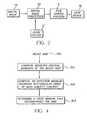
- FIG. 3A block diagram of the inventive cropping process (e.g., the digital image understanding technology) is shown in Fig. 3 , which is discussed in relation to Figs. 5-12.
- Figs. 5-12illustrate the inventive process being applied to an original image shown in Fig. 5 .
- the belief mapis created using MSD.
- the present inventionautomatically determines a zoom factor (e.g. 1.5X) and a crop window 80 (as shown in Fig. 7 ), as referred to in item 201 of Fig. 3 .
- This zoom factoris selected by an automatic method based directly on the main subject belief map (e.g., an estimate of the size of the main subject).
- the crop windowis typically a rectangular window with a certain aspect ratio.
- the zoom factoris used subsequently by the digital image processor 20 shown in Fig. 1 .
- the zoom factoris used to communicate with the lens 12 to adjust the lens magnification setting. This adjustment allows the lens 12 to image the appropriate size of the photographic film sample 31 onto the photographic paper 38.
- regions of the belief mapare clustered and the lowest belief cluster (e.g., the background belief) is set to zero using a predefined threshold.
- the lowest belief clustere.g., the background belief
- sections of the image having a belief value below a certain thresholdare considered background sections.
- such sectionsare given a belief of zero for purposes of this embodiment of the invention.
- centroidor center-of-mass (used interchangeably hereon forth), of nonzero beliefs are computed. More specifically, in Fig. 5 the subject having the highest belief in the belief map is the woman and the stroller. Fig. 7 illustrates that the centroid of this subject is approximately the top of the baby's head.
- a proper crop windowis determined in item 203.
- a proper crop windowis determined in item 203.
- a proper crop windowis determined in item 203.
- Fig. 6illustrates that the effective bounding rectangle 70 is centered at approximately the top of the boy's head and approximately encompasses the region of high subject content.
- the aspect ratio of the original imageis maintained. Therefore, a crop window 80 is determined in item 303 such that it is the smallest rectangle of the original aspect ratio that encompasses the effective MBR 70.
- the initial position of the crop window p 80is centered at the centroid, as shown in Fig. 7 .
- the crop windowis 80 then moved so that the entire crop window is within the original image (e.g. item 205) as shown in Fig. 8 .
- the crop window 80is moved again so that all the regions of the highest belief values ("main subject") are included within the crop window and to create a margin 81, as shown in FIG. 9 .
- This process(e.g., 206) captures the entire subject of interest. Therefore, as shown in Fig. 9 , the top of the woman's head is included in the crop window. Compare this to Fig. 8 where the top of the woman's head was outside the crop window.
- Decision box 207determines whether an acceptable solution has been found, i.e., whether it is possible to include at least the regions of the highest belief values in the crop window.
- the windowis again moved, as shown in item 208, to optimize a subject content index for the crop window.
- the preferred embodiment of the present inventiondefines the subject content index as the sum of belief values within the crop window. It should be noted that the present invention specifies higher numerical belief values corresponding to higher main subject probability. Therefore, finding a numerical maximum of the sum of the belief values is equivalent to finding an optimum of the subject content index. This is shown in Fig. 10 where the secondary objects (e.g. flowers) are included within the crop window 80 to increase the sum of beliefs.
- the sum of beliefs for a crop windowis computed as follows.
- the position of the center of the crop windowis used to calculate the translational component of the film sample position 9.
- the gate device 36shown in Fig. 1a , receives the film sample position 9 and uses this information to control the position of the photographic film sample 31 relative to the lens 12.
- the lens 12 and the photographic film sample 31may be moved to achieve the centering of the effective cropped image region on the photographic paper 38.
- the final position of the crop windowis restored to that of item 205. Then, referring to Fig. 1a , the position of the center of the crop window is used to calculate the translational component of the film sample position 9.
- the gate device 36shown in Fig. 1 , receives the film sample position 9 and uses this information to control the position of the photographic film sample 31 relative to the lens 12.
- the simulated image example shown in Figs. 5-12illustrates the progress the invention makes as it moves through the process shown in Fig. 3 .
- the procedure used in the inventionis considered a "greedy" searching approach and is certainly more efficient than conventional processes.
- the inventionutilizes a built-in "k-means” clustering process to determine proper thresholds of MSD beliefs for each application.
- the inventionalso uses clustering, as discussed below to enhance the cropping process.
- the inventionis not limited to simply three levels of classification, but instead can utilize a reasonable number of classification levels to reduce the (unnecessary) variation in the belief map. These three levels allow for the main subject (high), the background (low), and an intermediate level (medium) to capture secondary subjects, or uncertainty, or salient regions of background.
- clusteringhelps background separation by grouping low-belief background regions together to form a uniformly low-belief (e.g., zero belief) background region.
- clusteringhelps remove noise in belief ordering by grouping similar belief levels together. The centroiding operation does not need such quantization (nor should it be affected by the quantization).
- the main purpose of the quantization used hereis to provide a threshold for the background.
- threshold lowC low + C medium / 2
- threshold highC medium + C high / 2
- ⁇ C low , C medium , C high ⁇is the set of centroids (average belief values) for the three clusters
- threshold low and threshold highare the low and high thresholds, respectively.
- Regions with belief values below the lower thresholdare considered “background” and their belief values are set to zero in items 202, 302 and 402 discussed above. Regions with belief values above the higher threshold are considered part of the main subject and need to be included in their entirety, whenever possible. Regions with intermediate belief values (e.g., less than or equal to the higher threshold and greater than or equal to the lower threshold) are considered part of the "secondary subject" and will be included as a whole or partially, if possible, to maximize the sum of main subject belief values retained by the crop window. Note that the variance statistics on the three clusters can be used to set the thresholds more accurately to reflect cluster dispersions.
- the zoom versioneffectively requires higher spatial resolution than the highest resolution of the original data. However, a visible loss of image sharpness is likely of concern in the situation.
- the zoom versioneffectively requires lower spatial resolution than the highest resolution of the original data.
- the inventionuses an interpolation process to resample the data in order to retain a maximum amount of image detail.
- edge or detail-preserving image interpolation processessuch as cubic-spline interpolation are preferred because they tend to preserve the detail and sharpness of the original image better.
- FIGS. 13-15Example consumer photographs and their various cropped versions are shown in pictures "house” (e.g., FIGS. 13-15 ) and "volleyball" ( Figs. 16-18 ). More specifically, Figs. 13 and 16 illustrate uncropped original photographic images. Figs. 14 and 17 illustrate belief maps, with lighter regions indicating higher belief values. As would be known by one ordinarily skilled in the art given this disclosure, the light intensity variations shown in Figs. 14 and 17 are readily converted into numerical values for calculating the sum of the belief values discussed above. Finally, Figs. 15 and 18 illustrate images cropped according to the invention.
- a computer program productmay include one or more storage medium, for example; magnetic storage media such as magnetic disk (such as a floppy disk) or magnetic tape; optical storage media such as optical disk, optical tape, or machine readable bar code; solid-state electronic storage devices such as random access memory (RAM), or read-only memory (ROM); or any other physical device or media employed to store a computer program having instructions for practicing a method according to the present invention.
- magnetic storage mediasuch as magnetic disk (such as a floppy disk) or magnetic tape
- optical storage mediasuch as optical disk, optical tape, or machine readable bar code
- solid-state electronic storage devicessuch as random access memory (RAM), or read-only memory (ROM); or any other physical device or media employed to store a computer program having instructions for practicing a method according to the present invention.
- the subject matter of the present inventionrelates to digital image understanding technology, which is understood to mean technology that digitally processes a digital image to recognize and thereby assign useful meaning to human understandable objects, attributes or conditions and then to utilize the results obtained in the further processing of the digital image.
Landscapes
- Engineering & Computer Science (AREA)
- Physics & Mathematics (AREA)
- General Physics & Mathematics (AREA)
- Multimedia (AREA)
- Theoretical Computer Science (AREA)
- Signal Processing (AREA)
- Geometry (AREA)
- Computer Vision & Pattern Recognition (AREA)
- Image Processing (AREA)
- Editing Of Facsimile Originals (AREA)
- Image Analysis (AREA)
Description
- This invention relates in general to producing an image of a portion of a photographic image by using digital image processing.
- For many decades, traditional commercial photofinishing systems have placed limits on the features offered to consumers to promote mass production. Among those features that are unavailable conventionally, zooming and cropping have been identified by both consumers and photofinishers as extremely useful additional features that could potentially improve the quality of the finished photographs and the subsequent picture sharing experiences. With the advent of, and rapid advances in digital imaging, many of the technical barriers that existed in traditional photography no longer stand insurmountable.
- Hybrid and digital photography provide the ability to crop undesirable content from a picture, and magnify or zoom the desired content to fill the entire photographic print. In spite of the fact that some traditional cameras with zoom capability provide consumers greater control over composing the desired scene content, studies have found that photographers may still wish to perform a certain amount of cropping and zooming when viewing the finished photograph at a later time. Imprecise viewfinders of many point-and-shoot cameras, as well as simply second-guessing their initial compositions, are factors in the desirability of zoom and crop. In addition, it may be desirable to use some other regular border templates such as ovals, heart shapes, squares, etc. In another scenario, some people commonly referred to as "scrapbookers" tend to perform more aggressive crop in making a scrapbook, e.g., cutting along the boundary of objects.
- There are significant differences in objectives and behaviors between these two types of cropping, namely album-making and scrapbook making, with the latter more difficult to understand and summarize. The invention described below performs automatic zooming and cropping for making photographic prints. One customer focus group study indicated that it would be beneficial to provide customers a double set of prints -- one regular and one zoom. Moreover, it is preferred that the cropping and zooming be done automatically. Most customers do not want to think about how the zooming and cropping is being done as long as the content and quality (e.g., sharpness) of the cropped and zoomed pictures is acceptable.
- There has been little research on automatic zoom and crop due to the apparent difficulty involved in performing such a task. None of the known conventional image manipulation software uses scene content in determining the automatic crop amount. For example, a program entitled "XV", a freeware package developed by John Bradley at University of Pennsylvania, USA (Department of Computer and Information Science), provides an "autocrop" function for manipulating images and operates in the following way:
- the program examines a border line of an image, in all of the four directions, namely from the top, bottom, left and right sides;
- the program checks the variation within the line. In grayscale images, a line has to be uniform to be cropped. In color images, both the spatial correlation and spectral correlation have to be low, except for a small percentage of pixels, for the line to be qualified for cropping. In other words, a line will not be cropped if it contains a significant amount of variation;
- if a line along one dimension passes the criterion, the next line (row or column) inward is then examined; and
- the final cropped image is determined when the above recursive process stops.
- This program essentially tries to remove relatively homogeneous margins around the borders of an image. It does not examine the overall content of the image. In practice, the XV program is effective in cropping out the dark border generated due to imprecise alignment during the scanning process. However, disastrous results can often be produced due to the apparent lack of scene understanding. In some extreme cases, the entire image can be cropped.
- Another conventional system, described by Bollman et al. in
U.S. Patent US-A-5,978,519 provides a method for cropping images based upon the different intensity levels within the image. With this system, an image to be cropped is scaled down to a grid and divided into non-overlapping blocks. The mean and variance of intensity levels are calculated for each block. Based on the distribution of variances in the blocks, a threshold is selected for the variance. All blocks with a variance higher than the threshold variance are selected as regions of interest. The regions of interest are then cropped to a bounding rectangle. However, such a system is only effective when uncropped images contain regions where intensity levels are uniform and other regions where intensity levels vary considerably. The effectiveness of such a system is expected to be comparable to that of the XV program. The difference is that the XV program examines the image in a line by line fashion to identify uniform areas, while Bollman examines the image in a block by block fashion to identify uniform areas. - In summary, both techniques cannot deal with images with nonuniform background.
- In addition, in the earlier invention disclosed in
U.S. Patent US-A-6,654,506 , the zoom factor needs to be specified by the user. There is, therefore, a need for automatically determining the zoom factor in order to automate the entire zoom and crop process. - Some optical printing systems have the capability of changing the optical magnification of the relay lens used in the photographic copying process. In
U.S. Patent US-A-5,995,201 , Sakaguchi describes a method of varying the effective magnification of prints made from film originals utilizing a fixed optical lens instead of zoom lens. InU.S. Patent US-A-5,872,619 , Stephenson et al. describe a method of printing photographs from a processed photographic filmstrip having images of different widths measured longitudinally of the filmstrip and having heights measured transversely of the filmstrip. This method uses a photographic printer having a zoom lens and a printing mask to provide printed images having a selected print width and a selected print height. InU.S. Patent US-A-4,809,064 , Amos et al. describe an apparatus for printing a selected region of a photographic negative onto a photosensitive paper to form an enlarged and cropped photographic print. This apparatus includes means for projecting the photographic negative onto first and second zoom lenses, each of the zoom lenses having an adjustable magnification. InU.S. Patent US-A-5,872,643 , Maeda et al. describe a film reproducing apparatus that can effectively perform zoom and crop. This apparatus includes an image pick-up device which picks up a film frame image recorded on a film to generate image data, an information reader which reads information about photographing conditions of the film frame image, and a reproducing area designator which designates a reproducing area of the film frame image. However, the reproducing area of the film frame image is determined based on pre-recorded information about the position of the main object, as indicated by which zone of the photograph the automatic focusing (AF) operation in the camera was on - part of the recorded information about photographing conditions. In all the above-mentioned optical printing systems, the position of the photographic film sample and magnification factor of the relay lens are pre-selected. - According to the present invention, there is provided a solution to the problems of the prior art. It is an object of the present invention to provide a method for producing a portion of a photographic image by identifying the main subject of the photographic image. The use of crop windows for digital images is set forth in
EP - A-1158464 andEP-A-0975146 . - According to the present invention, there is provided a method of producing an image of a cropped portion of a digital image derived from a photographic film sample onto a photographic receiver having the steps of:
- a) receiving a digital image (10) having pixels;
- b) computing a belief map of the digital image(200), the belief map having belief values, by using the pixels of the digital image to determine a series of features, and using such features to assign to regions of the image the belief values which represent the likelihood of the regions being the location of a main subject of the digital image, in the belief map characterized by;
- c) computing a crop window having a shape and a zoom factor (203), the shape and zoom factor determining a size of the crop window, based on the belief values in the belief map by:
- i) computing a weighted center-of-mass of the belief map, weighted by the belief values of the belief map;
- ii) computing weighted central moments (301) of the belief map, relative to the center-of-mass and weighted by a weighting function of each belief value of the belief map;
- vii) computing an effective rectangular bounding box (302) according to the central moments; and
- viii) determining a crop window (303) having a shape and a zoom factor, the shape and zoom factor determining a size of the crop window;
- d) cropping the digital image (209) to include a portion of the digital image of high subject content in response to the belief map and the computed crop window; and
- e) positioning a lens assembly (12) and said photographic film sample (31) relative to one another using the computed crop window, and in response to the belief map and an illuminated image corresponding to the cropped portion (209) of the digital images (10) producing an image of such cropped portion onto the photographic receiver (38).
- One advantage of the invention lies in the ability to automatically crop and zoom photographic images based upon the scene contents. The digital image processing steps employed by the present invention include a step of identifying the main subject within the digital image. The present invention uses the identified main subject of the digital image to automatically zoom and crop the image. Therefore, the present invention produces high-quality zoomed or cropped images automatically, regardless whether the background is uniform or not.
- The foregoing and other objects, aspects and advantages will be better understood from the following detailed description of a preferred embodiment of the invention with reference to the drawings, in which:
Fig. 1 is a schematic diagram of a system embodiment of the invention;Fig. 2 is a schematic architectural diagram of an embodiment of the invention;Fig. 3 is a schematic architectural diagram of an embodiment of the invention;Fig. 4 is a schematic architectural diagram of an embodiment of the invention;Fig. 5 illustrates the application of the invention to a simulated photograph;Fig. 6 illustrates the application of the invention to a simulated photograph;Fig. 7 illustrates the application of the invention to a simulated photograph;Fig. 8 illustrates the application of the invention to a simulated photograph;Fig. 9 illustrates the application of the invention to a simulated photograph;Fig. 10 illustrates the application of the invention to a simulated photograph;Fig. 11 illustrates the application of the invention to a simulated photograph;Fig. 12 illustrates the application of the invention to a simulated photograph;Fig. 13 is an exemplary uncropped photograph;Fig. 14 is a belief map of the image shown inFIG. 13 ;Fig. 15 is a cropped version of the image shown inFIG. 13 ;Fig. 17 is a belief map of the image shown inFIG. 16 ; andFig. 18 is a cropped version of the image shown inFIG. 16 .- The invention automatically zooms and crops digital images according to an analysis of the main subject in the scene. Previously, a system for detecting main subjects (e.g., main subject detection or "MSD") in a consumer-type photographic image from the perspective of a third-party observer has been developed and is described in
U.S. Patent US-A-6,282,317 . Main subject detection provides a measure of saliency or relative importance for different regions that are associated with different subjects in an image. Main subject detection enables a discriminative treatment of the scene content for a number of applications related to consumer photographic images, including automatic crop and zoom. - Conventional wisdom in the field of computer vision, which reflects how a human observer would perform such tasks as main subject detection and cropping, calls for a problem-solving path via object recognition and scene content determination according to the semantic meaning of recognized objects. However, generic object recognition remains a largely unsolved problem despite decades of effort from academia and industry.
- The MSD system is built upon mostly low-level vision features with semantic information integrated whenever available. This MSD system has a number of sub-tasks, including region segmentation, perceptual grouping, feature extraction, and probabilistic and semantic reasoning. In particular, a large number of features are extracted for each segmented region in the image to represent a wide variety of visual saliency properties, which are then input into a tunable, extensible probability network to generate a belief map containing a continuum of values.
- Using MSD, regions that belong to the main subject are generally differentiated from the background clutter in the image. Thus, automatic zoom and crop becomes possible. Automatic zoom and crop is a nontrivial operation that was considered impossible for unconstrained images, which do not necessarily contain uniform background, without a certain amount of scene understanding. In the absence of content-driven cropping, conventional systems have concentrated on simply using a centered crop at a fixed zoom (magnification) factor, or removing the uniform background touching the image borders. The centered crop has been found unappealing to customers.
- The output of MSD used by the invention is a list of segmented regions ranked in descending order of their likelihood (or belief) as potential main subjects for a generic or specific application. This list can be readily converted into a map in which the brightness of a region is proportional to the main subject belief of the region. Therefore, this map can be called a main subject "belief' map. This "belief" map is more than a binary map that only indicates location of the determined main subject. The associated likelihood is also attached to each region so that regions with large values correspond to regions with high confidence or belief of being part of the main subject.
- To some extent, this belief map reflects the inherent uncertainty for humans to perform such a task as MSD because different observers may disagree on certain subject matter while agreeing on other subject matter in terms of main subjects. However, a binary decision, when desired, can be readily obtained by using an appropriate threshold on the belief map. Moreover, the belief information may be very useful for downstream applications. For example, different weighting factors can be assigned to different regions (subject matters) in determining the amount of crop.
- For determination of crop, the invention uses the main subject belief map instead of a binarized version of the map to avoid making a bad cropping decision that is irreversible. Furthermore, using the continuous values of the main subject beliefs helps trade-off different regions under the constraints encountered in cropping. A binary decision on what to include and what not to include, once made, leaves little room for trade-off. For example, if the main subject region is smaller than the crop window, the only reasonable choice, given a binary main subject map, is to leave equal amounts of margin around the main subject region. On the other hand, secondary main subjects are indicated by lower belief values in the main subject belief map, and can be included according to a descending order of belief values once the main subject of highest belief values are included. Moreover, if an undesirable binary decision on what to include/exclude is made, there is no recourse to correct the mistake. Consequently, the cropping result becomes sensitive to the threshold used to obtain the binary decision. With a continuous-valued main subject belief map, every region or object is associated with a likelihood of being included or a belief value in its being included.
- To reduce the degrees of freedom in determining the amount of crop, and to limit the amount of resolution loss incurred in the zoom process, in particular for making photographic prints, in one embodiment, the invention restricts the set of allowable zoom factors to the range of [192, 4]. This is based on the findings in the customer focus studies. Those skilled in the art would recognize that the present invention could be used with any other zoom factor.
- To reduce the degrees of freedom in determining the amount of crop, in particular for making photographic prints, in one embodiment, the invention restricts the set of allowable zoom factors to the range of [1.2, 4.0]. This is based on the findings in the customer focus studies. In addition, an extremely large zoom factor usually leads to blurry and unacceptable picture due to the limit imposed by the resolution of the original image. If a zoom factor determined by the present invention falls within the range of acceptable zoom factors (e.g., between 1.2 and 4.0), it will be used in the subsequent cropping process. Otherwise, the zoom factor is clipped to 1.2 at the lower end and 4.0 at the higher end.
- Referring to
Fig. 1 , the following description relates to a digital printing system. A sourcedigital image 10 is received by adigital image processor 20. Thedigital image processor 20 may be connected to ageneral control computer 40 under operator control from aninput control device 60. Themonitor device 50 displays diagnostic information about the digital printing system. The generaldigital image processor 20 performs the needed image processing to produce a cropped and zoomeddigital image 99. - Referring to
Fig. 1a , the following description relates to an optical printing system. Aphotographic film sample 31 is received by afilm scanner 32 which produces a sourcedigital image 10 relating to the spatial density distribution of the photographic film sample. This source digital image is received by adigital image processor 20. Thedigital image processor 20 may be connected to ageneral control computer 40 under operator control from aninput control device 60. Themonitor device 50 displays diagnostic information about the optical printing system. Thegeneral control computer 40 keeps track of the lens magnification setting. - Referring to
Fig. 2 , azoom factor 11, which corresponds to the lens magnification setting may also received by theimage processor 20 from thegeneral control computer 40 under operator control. Theimage processor 20 receives the sourcedigital image 10 and uses thezoom factor 11 and the sourcedigital image 10 to calculate the proper position for the photographic film sample in the form of afilm sample position 9. The photographic film sample is positioned in agate device 36 which holds the film negative in place during the exposure. Thegate device 36 receives thefilm sample position 9 to position the photographic film sample to adjust which portion of the imaging area of the photograph will be printed. - Referring to
Fig. 1a , a lamp house 34 provides the illumination source which is transmitted through thephotographic film sample 31 and focused by alens 12 ontophotographic paper 38. Thetime integration device 13 opens and closes a shutter for a variable length of time allowing the focused light from the lamp house 34 to expose thephotographic paper 38. Theexposure control device 16 receives a brightness balance value from thedigital image processor 20. Theexposure control device 16 uses the brightness balance value to regulate the length of time the shutter of the time integration device stays open. - A block diagram of the inventive cropping process (e.g., the digital image understanding technology) is shown in
Fig. 3 , which is discussed in relation toFigs. 5-12. Figs. 5-12 illustrate the inventive process being applied to an original image shown inFig. 5 . - In
item 200, the belief map is created using MSD. The present invention automatically determines a zoom factor (e.g. 1.5X) and a crop window 80 (as shown inFig. 7 ), as referred to initem 201 ofFig. 3 . This zoom factor is selected by an automatic method based directly on the main subject belief map (e.g., an estimate of the size of the main subject). The crop window is typically a rectangular window with a certain aspect ratio. After the zoom factor is determined by thedigital image processor 20, the value of the zoom factor is used subsequently by thedigital image processor 20 shown inFig. 1 . InFig. 1a , the zoom factor is used to communicate with thelens 12 to adjust the lens magnification setting. This adjustment allows thelens 12 to image the appropriate size of thephotographic film sample 31 onto thephotographic paper 38. - In
item 201, regions of the belief map are clustered and the lowest belief cluster (e.g., the background belief) is set to zero using a predefined threshold. As discussed in greater detail below, sections of the image having a belief value below a certain threshold are considered background sections. In item 202 such sections are given a belief of zero for purposes of this embodiment of the invention. - Then, in item 202 the centroid, or center-of-mass (used interchangeably hereon forth), of nonzero beliefs are computed. More specifically, in
Fig. 5 the subject having the highest belief in the belief map is the woman and the stroller.Fig. 7 illustrates that the centroid of this subject is approximately the top of the baby's head. - The centroid (x̂,ŷ) of a belief map is calculated using the following procedure:

- Before the crop window is placed, a proper crop window is determined in
item 203. Referring toFig. 4 , there is shown a block diagram of a method that automatically determines a zoom factor in response to the belief map. In item 301, two second-order central moments,cxx andcyy, with respect to the center-of-mass, are computed using the following procedure:
- Note that these two terms are not the conventional central moments that are computed without any weighting functions. In the preferred embodiment, a linear weighting function of the belief values is used. However, the conventional central moments, or central moments by a nonlinear function of the belief values, can also be used.
- An effective bounding rectangle (MBR) of the regions of high subject content can be calculated using the following procedure, where the dimensions of the MBR are calculated by:

Fig. 6 illustrates that theeffective bounding rectangle 70 is centered at approximately the top of the boy's head and approximately encompasses the region of high subject content. In general, the aspect ratio of the original image is maintained. Therefore, acrop window 80 is determined initem 303 such that it is the smallest rectangle of the original aspect ratio that encompasses theeffective MBR 70.- In item 204, the initial position of the
crop window p 80 is centered at the centroid, as shown inFig. 7 . - The crop window is 80 then moved so that the entire crop window is within the original image (e.g. item 205) as shown in
Fig. 8 . Initem 206, thecrop window 80 is moved again so that all the regions of the highest belief values ("main subject") are included within the crop window and to create amargin 81, as shown inFIG. 9 . This process (e.g., 206) captures the entire subject of interest. Therefore, as shown inFig. 9 , the top of the woman's head is included in the crop window. Compare this toFig. 8 where the top of the woman's head was outside the crop window. Decision box 207 determines whether an acceptable solution has been found, i.e., whether it is possible to include at least the regions of the highest belief values in the crop window.- If an acceptable solution exists, the window is again moved, as shown in
item 208, to optimize a subject content index for the crop window. The preferred embodiment of the present invention defines the subject content index as the sum of belief values within the crop window. It should be noted that the present invention specifies higher numerical belief values corresponding to higher main subject probability. Therefore, finding a numerical maximum of the sum of the belief values is equivalent to finding an optimum of the subject content index. This is shown inFig. 10 where the secondary objects (e.g. flowers) are included within thecrop window 80 to increase the sum of beliefs. The sum of beliefs for a crop window is computed as follows.
- Provided that the primary subjects are included, moving the crop window so that more of the secondary subjects are included would increase the sum of belief values within the crop window. Recall that the primary subjects are indicated by the highest belief values and the secondary subjects are indicated by belief values lower than those of the primary subjects but higher than those of the background subjects. The goal is to find the crop window that has the highest sum of belief values while ensuring that the primary subjects are completely included in the crop window, i.e.,

- Then, in item 212 (in place of
item 209, not shown), the position of the center of the crop window is used to calculate the translational component of thefilm sample position 9. Thegate device 36, shown inFig. 1a , receives thefilm sample position 9 and uses this information to control the position of thephotographic film sample 31 relative to thelens 12. Those skilled in the art will recognize that either or both of thelens 12 and thephotographic film sample 31 may be moved to achieve the centering of the effective cropped image region on thephotographic paper 38. - Referring to
Fig. 3 , ifdecision box 207 does not produce an acceptable solution, the final position of the crop window is restored to that ofitem 205. Then, referring toFig. 1a , the position of the center of the crop window is used to calculate the translational component of thefilm sample position 9. Thegate device 36, shown inFig. 1 , receives thefilm sample position 9 and uses this information to control the position of thephotographic film sample 31 relative to thelens 12. - The simulated image example shown in
Figs. 5-12 illustrates the progress the invention makes as it moves through the process shown inFig. 3 . One could formulate the problem as a global exhaustive search for the best solution. The procedure used in the invention is considered a "greedy" searching approach and is certainly more efficient than conventional processes. - The invention utilizes a built-in "k-means" clustering process to determine proper thresholds of MSD beliefs for each application. The invention also uses clustering, as discussed below to enhance the cropping process. In one preferred embodiment, it is sufficient to use three levels to quantize MSD beliefs, namely "high", "medium", and "low." As would be known by one ordinarily skilled in the art, the invention is not limited to simply three levels of classification, but instead can utilize a reasonable number of classification levels to reduce the (unnecessary) variation in the belief map. These three levels allow for the main subject (high), the background (low), and an intermediate level (medium) to capture secondary subjects, or uncertainty, or salient regions of background. Therefore, the invention can perform a k-means clustering with k = 3 on the MSD belief map to "quantize" the beliefs. Consequently, the belief for each region is replaced by the mean belief of the cluster in that region. Note that a k-means clustering with k = 2 essentially produces a binary map with two clusters, "high" and "low," which is undesirable for cropping based on earlier discussion.
- There are two major advantages in performing such clustering or quantization. First, clustering helps background separation by grouping low-belief background regions together to form a uniformly low-belief (e.g., zero belief) background region. Second, clustering helps remove noise in belief ordering by grouping similar belief levels together. The centroiding operation does not need such quantization (nor should it be affected by the quantization). The main purpose of the quantization used here is to provide a threshold for the background.
- The k-means clustering effectively performs a multi-level thresholding operation to the belief map. After clustering, two thresholds can be determined as follows:


- Regions with belief values below the lower threshold are considered "background" and their belief values are set to zero in
items 202, 302 and 402 discussed above. Regions with belief values above the higher threshold are considered part of the main subject and need to be included in their entirety, whenever possible. Regions with intermediate belief values (e.g., less than or equal to the higher threshold and greater than or equal to the lower threshold) are considered part of the "secondary subject" and will be included as a whole or partially, if possible, to maximize the sum of main subject belief values retained by the crop window. Note that the variance statistics on the three clusters can be used to set the thresholds more accurately to reflect cluster dispersions. - The invention initializes the k-means process by finding the maximum valuebelmaximum and minimum valuesbelminimum of the belief map, computing the average valuebelaverage of the maximum and minimum values for item in the belief map, and setting the initial centroids (denoted by a superscript of 0) at these three values, i.e.,

- Other ways of initialization may apply. For more about the
k-means process, see Sonka, Hlavac, and Boyle, Image Procesing Analysis, and MachineVision, PWS Publishing, 1999 pagse 307-308. For typical MSD belief maps, the k-means process usually converges in fewer than 10 iterations. - In applications where a zoom version of the cropped area is desired, there are two scenarios to consider. First, the zoom version effectively requires higher spatial resolution than the highest resolution of the original data. However, a visible loss of image sharpness is likely of concern in the situation. Second, the zoom version effectively requires lower spatial resolution than the highest resolution of the original data. In both cases, the invention uses an interpolation process to resample the data in order to retain a maximum amount of image detail. In general, edge or detail-preserving image interpolation processes such as cubic-spline interpolation are preferred because they tend to preserve the detail and sharpness of the original image better.
- Example consumer photographs and their various cropped versions are shown in pictures "house" (e.g.,
FIGS. 13-15 ) and "volleyball" (Figs. 16-18 ). More specifically,Figs. 13 and16 illustrate uncropped original photographic images.Figs. 14 and17 illustrate belief maps, with lighter regions indicating higher belief values. As would be known by one ordinarily skilled in the art given this disclosure, the light intensity variations shown inFigs. 14 and17 are readily converted into numerical values for calculating the sum of the belief values discussed above. Finally,Figs. 15 and18 illustrate images cropped according to the invention. - For the "house" picture, both Bradley and Bollman (
U.S. Patent US-A-5,978,519 ) would keep the entire image and not be able to produce a cropped image because of the shadows at the bottom and the tree extending to the top border of the uncropped image (Fig. 13 ). There are no continuous flat background regions extending from the image borders in this picture, as required byU.S. Patent US-A-5,978,519 . Similarly, the top of the tree inFig. 16 would not be cropped in the system disclosed inU.S. Patent US-A-5,978,519 . - Secondary subjects can lead to a more balanced cropped picture. For the "volleyball" picture (
Fig. 16 ), the inclusion of some parts of the tree by the algorithm leads to more interesting cropped pictures than simply placing the main subjects (players) in the center of the cropped image (Fig. 18 ). The invention was able to do so because the trees are indicated to be of secondary importance based on the belief mapFig. 17 . It is obvious that the art taught by Bradley and Bollman inU.S. Patent US-A-5,978,519 would not be able to produce such a nicely cropped image. In fact, both Bradley and Bollman (U.S. Patent US-A-5,978,519 ) would at best remove the entire lower lawn portion of the picture and keep the tree branches in the upper-left of the uncropped image. - A computer program product may include one or more storage medium, for example; magnetic storage media such as magnetic disk (such as a floppy disk) or magnetic tape; optical storage media such as optical disk, optical tape, or machine readable bar code; solid-state electronic storage devices such as random access memory (RAM), or read-only memory (ROM); or any other physical device or media employed to store a computer program having instructions for practicing a method according to the present invention.
- While the invention has been described in terms of preferred embodiments, those skilled in the art will recognize that the invention can be practiced with modification within the scope of the appended claims.
- The subject matter of the present invention relates to digital image understanding technology, which is understood to mean technology that digitally processes a digital image to recognize and thereby assign useful meaning to human understandable objects, attributes or conditions and then to utilize the results obtained in the further processing of the digital image.


Claims (1)
- A method of producing an image of a cropped portion of a digital image derived from a photographic film sample onto a photographic receiver having the steps of:a) receiving a digital image (10) having pixels;b) computing a belief map of the digital image(200), the belief map having belief values, by using the pixels of the digital image to determine a series of features, and using such features to assign to regions of the image the belief values which represent the likelihood of the regions being the location of a main subject of the digital image, in the belief mapcharacterized by;c) computing a crop window having a shape and a zoom factor (203), the shape and zoom factor determining a size of the crop window, based on the belief values in the belief map by:iii) computing a weighted center-of-mass of the belief map, weighted by the belief values of the belief map;iv) computing weighted central moments (301) of the belief map, relative to the center-of-mass and weighted by a weighting function of each belief value of the belief map;v) computing an effective rectangular bounding box (302) according to the central moments; andvi) determining a crop window (303) having a shape and a zoom factor, the shape and zoom factor determining a size of the crop window;d) cropping the digital image (209) to include a portion of the digital image of high subject content in response to the belief map and the computed crop window; ande) positioning a lens assembly (12) and said photographic film sample (31) relative to one another using the computed crop window, and, in response to the belief map and an illuminated image corresponding to the cropped portion (209) of the digital image (10) producing an image of such cropped portion onto the photographic receiver (38).
Applications Claiming Priority (2)
| Application Number | Priority Date | Filing Date | Title |
|---|---|---|---|
| US09/736,825US6654507B2 (en) | 2000-12-14 | 2000-12-14 | Automatically producing an image of a portion of a photographic image |
| US736825 | 2000-12-14 |
Publications (2)
| Publication Number | Publication Date |
|---|---|
| EP1215626A1 EP1215626A1 (en) | 2002-06-19 |
| EP1215626B1true EP1215626B1 (en) | 2008-09-03 |
Family
ID=24961437
Family Applications (1)
| Application Number | Title | Priority Date | Filing Date |
|---|---|---|---|
| EP01204654AExpired - LifetimeEP1215626B1 (en) | 2000-12-14 | 2001-12-03 | Automatically producing an image of a portion of a photographic image |
Country Status (4)
| Country | Link |
|---|---|
| US (1) | US6654507B2 (en) |
| EP (1) | EP1215626B1 (en) |
| JP (1) | JP3946030B2 (en) |
| DE (1) | DE60135622D1 (en) |
Cited By (20)
| Publication number | Priority date | Publication date | Assignee | Title |
|---|---|---|---|---|
| US11403069B2 (en) | 2017-07-24 | 2022-08-02 | Tesla, Inc. | Accelerated mathematical engine |
| US11409692B2 (en) | 2017-07-24 | 2022-08-09 | Tesla, Inc. | Vector computational unit |
| US11487288B2 (en) | 2017-03-23 | 2022-11-01 | Tesla, Inc. | Data synthesis for autonomous control systems |
| US11537811B2 (en) | 2018-12-04 | 2022-12-27 | Tesla, Inc. | Enhanced object detection for autonomous vehicles based on field view |
| US11562231B2 (en) | 2018-09-03 | 2023-01-24 | Tesla, Inc. | Neural networks for embedded devices |
| US11561791B2 (en) | 2018-02-01 | 2023-01-24 | Tesla, Inc. | Vector computational unit receiving data elements in parallel from a last row of a computational array |
| US11567514B2 (en) | 2019-02-11 | 2023-01-31 | Tesla, Inc. | Autonomous and user controlled vehicle summon to a target |
| US11610117B2 (en) | 2018-12-27 | 2023-03-21 | Tesla, Inc. | System and method for adapting a neural network model on a hardware platform |
| US11636333B2 (en) | 2018-07-26 | 2023-04-25 | Tesla, Inc. | Optimizing neural network structures for embedded systems |
| US11665108B2 (en) | 2018-10-25 | 2023-05-30 | Tesla, Inc. | QoS manager for system on a chip communications |
| US11681649B2 (en) | 2017-07-24 | 2023-06-20 | Tesla, Inc. | Computational array microprocessor system using non-consecutive data formatting |
| US11734562B2 (en) | 2018-06-20 | 2023-08-22 | Tesla, Inc. | Data pipeline and deep learning system for autonomous driving |
| US11748620B2 (en) | 2019-02-01 | 2023-09-05 | Tesla, Inc. | Generating ground truth for machine learning from time series elements |
| US11790664B2 (en) | 2019-02-19 | 2023-10-17 | Tesla, Inc. | Estimating object properties using visual image data |
| US11816585B2 (en) | 2018-12-03 | 2023-11-14 | Tesla, Inc. | Machine learning models operating at different frequencies for autonomous vehicles |
| US11841434B2 (en) | 2018-07-20 | 2023-12-12 | Tesla, Inc. | Annotation cross-labeling for autonomous control systems |
| US11893774B2 (en) | 2018-10-11 | 2024-02-06 | Tesla, Inc. | Systems and methods for training machine models with augmented data |
| US11893393B2 (en) | 2017-07-24 | 2024-02-06 | Tesla, Inc. | Computational array microprocessor system with hardware arbiter managing memory requests |
| US12014553B2 (en) | 2019-02-01 | 2024-06-18 | Tesla, Inc. | Predicting three-dimensional features for autonomous driving |
| US12307350B2 (en) | 2018-01-04 | 2025-05-20 | Tesla, Inc. | Systems and methods for hardware-based pooling |
Families Citing this family (126)
| Publication number | Priority date | Publication date | Assignee | Title |
|---|---|---|---|---|
| GB2370438A (en)* | 2000-12-22 | 2002-06-26 | Hewlett Packard Co | Automated image cropping using selected compositional rules. |
| WO2002052839A2 (en) | 2000-12-22 | 2002-07-04 | Hewlett-Packard Company | Image composition evaluation |
| AU2002258683A1 (en)* | 2001-03-30 | 2002-10-15 | Kodak Polychrome Graphics | Automated sharpening of images for soft proofing |
| GB0116113D0 (en)* | 2001-06-30 | 2001-08-22 | Hewlett Packard Co | Tilt correction of electronic images |
| GB2378340A (en)* | 2001-07-31 | 2003-02-05 | Hewlett Packard Co | Generation of an image bounded by a frame or of overlapping images |
| US7062085B2 (en)* | 2001-09-13 | 2006-06-13 | Eastman Kodak Company | Method for detecting subject matter regions in images |
| IL147370A (en)* | 2001-12-27 | 2007-07-24 | Itzhak Florentin | Method and system for guiding a remote vehicle via lagged communication channel |
| US7194125B2 (en)* | 2002-12-13 | 2007-03-20 | Mitsubishi Electric Research Laboratories, Inc. | System and method for interactively rendering objects with surface light fields and view-dependent opacity |
| JP3690391B2 (en)* | 2003-01-23 | 2005-08-31 | セイコーエプソン株式会社 | Image editing apparatus, image trimming method, and program |
| KR20040069865A (en)* | 2003-01-30 | 2004-08-06 | 삼성전자주식회사 | Device and method for extending character region-of-content of image |
| DE10315442A1 (en)* | 2003-04-03 | 2004-11-11 | Bts Media Solutions Gmbh | Process and circuit for scaling raster images |
| US7308158B2 (en) | 2003-06-20 | 2007-12-11 | Eastman Kodak Company | Imaging method and system |
| US7315630B2 (en) | 2003-06-26 | 2008-01-01 | Fotonation Vision Limited | Perfecting of digital image rendering parameters within rendering devices using face detection |
| US7471846B2 (en) | 2003-06-26 | 2008-12-30 | Fotonation Vision Limited | Perfecting the effect of flash within an image acquisition devices using face detection |
| US7792970B2 (en) | 2005-06-17 | 2010-09-07 | Fotonation Vision Limited | Method for establishing a paired connection between media devices |
| US8896725B2 (en) | 2007-06-21 | 2014-11-25 | Fotonation Limited | Image capture device with contemporaneous reference image capture mechanism |
| US7269292B2 (en) | 2003-06-26 | 2007-09-11 | Fotonation Vision Limited | Digital image adjustable compression and resolution using face detection information |
| US9129381B2 (en) | 2003-06-26 | 2015-09-08 | Fotonation Limited | Modification of post-viewing parameters for digital images using image region or feature information |
| US8494286B2 (en) | 2008-02-05 | 2013-07-23 | DigitalOptics Corporation Europe Limited | Face detection in mid-shot digital images |
| US7587068B1 (en) | 2004-01-22 | 2009-09-08 | Fotonation Vision Limited | Classification database for consumer digital images |
| US8593542B2 (en) | 2005-12-27 | 2013-11-26 | DigitalOptics Corporation Europe Limited | Foreground/background separation using reference images |
| US7844076B2 (en) | 2003-06-26 | 2010-11-30 | Fotonation Vision Limited | Digital image processing using face detection and skin tone information |
| US7574016B2 (en) | 2003-06-26 | 2009-08-11 | Fotonation Vision Limited | Digital image processing using face detection information |
| US8682097B2 (en) | 2006-02-14 | 2014-03-25 | DigitalOptics Corporation Europe Limited | Digital image enhancement with reference images |
| US7792335B2 (en) | 2006-02-24 | 2010-09-07 | Fotonation Vision Limited | Method and apparatus for selective disqualification of digital images |
| US7680342B2 (en) | 2004-08-16 | 2010-03-16 | Fotonation Vision Limited | Indoor/outdoor classification in digital images |
| US7317815B2 (en)* | 2003-06-26 | 2008-01-08 | Fotonation Vision Limited | Digital image processing composition using face detection information |
| US8155397B2 (en) | 2007-09-26 | 2012-04-10 | DigitalOptics Corporation Europe Limited | Face tracking in a camera processor |
| US8553949B2 (en) | 2004-01-22 | 2013-10-08 | DigitalOptics Corporation Europe Limited | Classification and organization of consumer digital images using workflow, and face detection and recognition |
| US9692964B2 (en) | 2003-06-26 | 2017-06-27 | Fotonation Limited | Modification of post-viewing parameters for digital images using image region or feature information |
| US8363951B2 (en) | 2007-03-05 | 2013-01-29 | DigitalOptics Corporation Europe Limited | Face recognition training method and apparatus |
| US8989453B2 (en) | 2003-06-26 | 2015-03-24 | Fotonation Limited | Digital image processing using face detection information |
| US7616233B2 (en)* | 2003-06-26 | 2009-11-10 | Fotonation Vision Limited | Perfecting of digital image capture parameters within acquisition devices using face detection |
| US7362368B2 (en)* | 2003-06-26 | 2008-04-22 | Fotonation Vision Limited | Perfecting the optics within a digital image acquisition device using face detection |
| US8330831B2 (en) | 2003-08-05 | 2012-12-11 | DigitalOptics Corporation Europe Limited | Method of gathering visual meta data using a reference image |
| US7440593B1 (en) | 2003-06-26 | 2008-10-21 | Fotonation Vision Limited | Method of improving orientation and color balance of digital images using face detection information |
| US7565030B2 (en) | 2003-06-26 | 2009-07-21 | Fotonation Vision Limited | Detecting orientation of digital images using face detection information |
| US8948468B2 (en) | 2003-06-26 | 2015-02-03 | Fotonation Limited | Modification of viewing parameters for digital images using face detection information |
| US7620218B2 (en) | 2006-08-11 | 2009-11-17 | Fotonation Ireland Limited | Real-time face tracking with reference images |
| US8498452B2 (en) | 2003-06-26 | 2013-07-30 | DigitalOptics Corporation Europe Limited | Digital image processing using face detection information |
| US7171058B2 (en)* | 2003-07-31 | 2007-01-30 | Eastman Kodak Company | Method and computer program product for producing an image of a desired aspect ratio |
| WO2005015355A2 (en)* | 2003-08-07 | 2005-02-17 | Matsushita Electric Industrial Co., Ltd. | Automatic image cropping system and method for use with portable devices equipped with digital cameras |
| JP2005123707A (en)* | 2003-10-14 | 2005-05-12 | Casio Comput Co Ltd | Imaging projection apparatus and imaging projection system, display image generation apparatus, and display image generation method |
| KR100604011B1 (en)* | 2004-01-02 | 2006-07-24 | 엘지전자 주식회사 | Image processing apparatus and method |
| US7551755B1 (en) | 2004-01-22 | 2009-06-23 | Fotonation Vision Limited | Classification and organization of consumer digital images using workflow, and face detection and recognition |
| US7558408B1 (en) | 2004-01-22 | 2009-07-07 | Fotonation Vision Limited | Classification system for consumer digital images using workflow and user interface modules, and face detection and recognition |
| US7564994B1 (en) | 2004-01-22 | 2009-07-21 | Fotonation Vision Limited | Classification system for consumer digital images using automatic workflow and face detection and recognition |
| US7555148B1 (en) | 2004-01-22 | 2009-06-30 | Fotonation Vision Limited | Classification system for consumer digital images using workflow, face detection, normalization, and face recognition |
| JP4214926B2 (en)* | 2004-03-04 | 2009-01-28 | 株式会社ニコン | Electronic still camera |
| US7777902B2 (en)* | 2004-05-03 | 2010-08-17 | Microsoft Corporation | System and method for generating resolution-independent output via visual tree object |
| US20060050089A1 (en)* | 2004-09-09 | 2006-03-09 | Atousa Soroushi | Method and apparatus for selecting pixels to write to a buffer when creating an enlarged image |
| US8504110B2 (en)* | 2004-09-10 | 2013-08-06 | Interdigital Technology Corporation | Method and apparatus for transferring smart antenna capability information |
| US20060056345A1 (en)* | 2004-09-10 | 2006-03-16 | Interdigital Technology Corporation | Method and system for supporting use of a smart antenna in a wireless local area network |
| US8320641B2 (en) | 2004-10-28 | 2012-11-27 | DigitalOptics Corporation Europe Limited | Method and apparatus for red-eye detection using preview or other reference images |
| US7688364B2 (en)* | 2004-12-10 | 2010-03-30 | Ambarella, Inc. | Decimating and cropping based zoom factor for a digital camera |
| KR100624473B1 (en) | 2004-12-14 | 2006-09-18 | 삼성전자주식회사 | Image processing apparatus and method |
| US8503800B2 (en) | 2007-03-05 | 2013-08-06 | DigitalOptics Corporation Europe Limited | Illumination detection using classifier chains |
| US7715597B2 (en) | 2004-12-29 | 2010-05-11 | Fotonation Ireland Limited | Method and component for image recognition |
| US7315631B1 (en) | 2006-08-11 | 2008-01-01 | Fotonation Vision Limited | Real-time face tracking in a digital image acquisition device |
| KR100777462B1 (en)* | 2005-01-19 | 2007-11-21 | 삼성전자주식회사 | Scanning apparatus, scanning system having same and scanning method |
| GB2422739B (en)* | 2005-01-31 | 2010-07-14 | Hewlett Packard Development Co | Image processing method and apparatus |
| US7715589B2 (en)* | 2005-03-07 | 2010-05-11 | Massachusetts Institute Of Technology | Occluding contour detection and storage for digital photography |
| US7760956B2 (en) | 2005-05-12 | 2010-07-20 | Hewlett-Packard Development Company, L.P. | System and method for producing a page using frames of a video stream |
| US8054513B2 (en)* | 2005-07-20 | 2011-11-08 | Brother Kogyo Kabushiki Kaisha | Image displaying method, image display apparatus and facsimile apparatus for displaying effective data on display screen |
| EP1748385A3 (en)* | 2005-07-28 | 2009-12-09 | THOMSON Licensing | Method and device for generating a sequence of images of reduced size |
| US7529390B2 (en)* | 2005-10-03 | 2009-05-05 | Microsoft Corporation | Automatically cropping an image |
| US7804983B2 (en) | 2006-02-24 | 2010-09-28 | Fotonation Vision Limited | Digital image acquisition control and correction method and apparatus |
| EP2033142B1 (en) | 2006-06-12 | 2011-01-26 | Tessera Technologies Ireland Limited | Advances in extending the aam techniques from grayscale to color images |
| US7515740B2 (en) | 2006-08-02 | 2009-04-07 | Fotonation Vision Limited | Face recognition with combined PCA-based datasets |
| US7403643B2 (en) | 2006-08-11 | 2008-07-22 | Fotonation Vision Limited | Real-time face tracking in a digital image acquisition device |
| US7916897B2 (en) | 2006-08-11 | 2011-03-29 | Tessera Technologies Ireland Limited | Face tracking for controlling imaging parameters |
| US8055067B2 (en) | 2007-01-18 | 2011-11-08 | DigitalOptics Corporation Europe Limited | Color segmentation |
| US20080183844A1 (en)* | 2007-01-26 | 2008-07-31 | Andrew Gavin | Real time online video editing system and method |
| US8218830B2 (en)* | 2007-01-29 | 2012-07-10 | Myspace Llc | Image editing system and method |
| US20080199098A1 (en)* | 2007-02-19 | 2008-08-21 | Seiko Epson Corporation | Information processing method, information processing apparatus, and storage medium having program stored thereon |
| JP5049356B2 (en) | 2007-02-28 | 2012-10-17 | デジタルオプティックス・コーポレイション・ヨーロッパ・リミテッド | Separation of directional lighting variability in statistical face modeling based on texture space decomposition |
| WO2008109622A1 (en) | 2007-03-05 | 2008-09-12 | Fotonation Vision Limited | Face categorization and annotation of a mobile phone contact list |
| JP4970557B2 (en) | 2007-03-05 | 2012-07-11 | デジタルオプティックス・コーポレイション・ヨーロッパ・リミテッド | Face search and detection in digital image capture device |
| US7934011B2 (en)* | 2007-05-01 | 2011-04-26 | Flektor, Inc. | System and method for flow control in web-based video editing system |
| US7916971B2 (en) | 2007-05-24 | 2011-03-29 | Tessera Technologies Ireland Limited | Image processing method and apparatus |
| US7676145B2 (en)* | 2007-05-30 | 2010-03-09 | Eastman Kodak Company | Camera configurable for autonomous self-learning operation |
| US7817914B2 (en)* | 2007-05-30 | 2010-10-19 | Eastman Kodak Company | Camera configurable for autonomous operation |
| US8750578B2 (en) | 2008-01-29 | 2014-06-10 | DigitalOptics Corporation Europe Limited | Detecting facial expressions in digital images |
| US7855737B2 (en) | 2008-03-26 | 2010-12-21 | Fotonation Ireland Limited | Method of making a digital camera image of a scene including the camera user |
| JP2009268085A (en)* | 2008-03-31 | 2009-11-12 | Fujifilm Corp | Image trimming device and program |
| CN103475837B (en) | 2008-05-19 | 2017-06-23 | 日立麦克赛尔株式会社 | Record reproducing device and method |
| US20090295787A1 (en)* | 2008-06-02 | 2009-12-03 | Amlogic, Inc. | Methods for Displaying Objects of Interest on a Digital Display Device |
| CN102027505A (en) | 2008-07-30 | 2011-04-20 | 泰塞拉技术爱尔兰公司 | Automatic face and skin retouching using face detection |
| US20100110210A1 (en)* | 2008-11-06 | 2010-05-06 | Prentice Wayne E | Method and means of recording format independent cropping information |
| WO2010063463A2 (en) | 2008-12-05 | 2010-06-10 | Fotonation Ireland Limited | Face recognition using face tracker classifier data |
| US9020298B2 (en)* | 2009-04-15 | 2015-04-28 | Microsoft Technology Licensing, Llc | Automated image cropping to include particular subjects |
| EP2249307B1 (en)* | 2009-05-05 | 2019-07-03 | InterDigital Madison Patent Holdings | Method for image reframing |
| RU2012108572A (en)* | 2009-08-11 | 2013-09-20 | Конинклейке Филипс Электроникс Н.В. | METHOD AND DEVICE FOR PROVIDING IMAGES FOR DISPLAY |
| US8379917B2 (en) | 2009-10-02 | 2013-02-19 | DigitalOptics Corporation Europe Limited | Face recognition performance using additional image features |
| JP2011176747A (en)* | 2010-02-25 | 2011-09-08 | Sony Corp | Image processing apparatus and method, and program |
| US8692867B2 (en) | 2010-03-05 | 2014-04-08 | DigitalOptics Corporation Europe Limited | Object detection and rendering for wide field of view (WFOV) image acquisition systems |
| JP5655334B2 (en)* | 2010-03-19 | 2015-01-21 | ソニー株式会社 | Image processing apparatus and method, and program |
| WO2011120588A1 (en)* | 2010-04-01 | 2011-10-06 | Hewlett-Packard Development Company, L.P. | Image enhancement |
| US8692907B2 (en)* | 2010-09-13 | 2014-04-08 | Sony Corporation | Image capturing apparatus and image capturing method |
| US8836777B2 (en) | 2011-02-25 | 2014-09-16 | DigitalOptics Corporation Europe Limited | Automatic detection of vertical gaze using an embedded imaging device |
| US8896703B2 (en) | 2011-03-31 | 2014-11-25 | Fotonation Limited | Superresolution enhancment of peripheral regions in nonlinear lens geometries |
| US8947501B2 (en) | 2011-03-31 | 2015-02-03 | Fotonation Limited | Scene enhancements in off-center peripheral regions for nonlinear lens geometries |
| US8682108B2 (en)* | 2011-04-11 | 2014-03-25 | Hewlett-Packard Development Company, L.P. | System and method for determining image placement on a canvas |
| US20120294514A1 (en)* | 2011-05-19 | 2012-11-22 | Xerox Corporation | Techniques to enable automated workflows for the creation of user-customized photobooks |
| EP2549754A1 (en) | 2011-07-19 | 2013-01-23 | Thomson Licensing | Method and apparatus for reframing and encoding an original video signal |
| US8811747B2 (en)* | 2011-10-28 | 2014-08-19 | Intellectual Ventures Fund 83 Llc | Image recomposition from face detection and facial features |
| US9025835B2 (en) | 2011-10-28 | 2015-05-05 | Intellectual Ventures Fund 83 Llc | Image recomposition from face detection and facial features |
| US8938100B2 (en) | 2011-10-28 | 2015-01-20 | Intellectual Ventures Fund 83 Llc | Image recomposition from face detection and facial features |
| US9008436B2 (en) | 2011-10-28 | 2015-04-14 | Intellectual Ventures Fund 83 Llc | Image recomposition from face detection and facial features |
| US9025836B2 (en) | 2011-10-28 | 2015-05-05 | Intellectual Ventures Fund 83 Llc | Image recomposition from face detection and facial features |
| US8867841B2 (en)* | 2012-08-08 | 2014-10-21 | Google Inc. | Intelligent cropping of images based on multiple interacting variables |
| KR102092846B1 (en)* | 2013-03-08 | 2020-03-24 | 삼성전자주식회사 | Image process apparatus and method for processing three-dimensional image zoom |
| US9202276B2 (en) | 2013-03-13 | 2015-12-01 | Restoration Robotics, Inc. | Methods and systems for hair transplantation using time constrained image processing |
| US9607235B2 (en)* | 2013-03-14 | 2017-03-28 | Facebook, Inc. | Image cropping according to points of interest |
| US9292756B2 (en)* | 2013-12-10 | 2016-03-22 | Dropbox, Inc. | Systems and methods for automated image cropping |
| CN104504651B (en)* | 2015-01-22 | 2017-11-14 | 网易(杭州)网络有限公司 | Preview drawing generating method and equipment |
| US11743402B2 (en)* | 2015-02-13 | 2023-08-29 | Awes.Me, Inc. | System and method for photo subject display optimization |
| US9916861B2 (en) | 2015-06-17 | 2018-03-13 | International Business Machines Corporation | Editing media on a mobile device before transmission |
| CN105225197A (en)* | 2015-09-14 | 2016-01-06 | 北京金山安全软件有限公司 | Picture clipping method and device |
| US10318794B2 (en) | 2017-04-28 | 2019-06-11 | Microsoft Technology Licensing, Llc | Intelligent auto cropping of digital images |
| US10861162B2 (en) | 2017-12-08 | 2020-12-08 | Ebay Inc. | Object identification in digital images |
| US11423570B2 (en)* | 2018-12-26 | 2022-08-23 | Intel Corporation | Technologies for fusing data from multiple sensors to improve object detection, identification, and localization |
| CN111696112B (en)* | 2020-06-15 | 2023-04-07 | 携程计算机技术(上海)有限公司 | Automatic image cutting method and system, electronic equipment and storage medium |
| CN112488108B (en)* | 2020-12-11 | 2024-08-13 | 广州小鹏自动驾驶科技有限公司 | Parking space number identification method and device, electronic equipment and storage medium |
| CN114693518A (en)* | 2022-02-15 | 2022-07-01 | 杭州印鸽科技有限公司 | Picture printing-oriented intelligent picture cutting method |
| EP4246441B1 (en)* | 2022-03-16 | 2025-08-06 | Arçelik Anonim Sirketi | A refrigerator with a camera for automatic image cropping |
Family Cites Families (17)
| Publication number | Priority date | Publication date | Assignee | Title |
|---|---|---|---|---|
| US4809064A (en) | 1987-11-19 | 1989-02-28 | Eastman Kodak Company | Enlarging photographic printer |
| JP3337768B2 (en)* | 1993-07-23 | 2002-10-21 | キヤノン株式会社 | Composite image forming apparatus and method of controlling composite image forming apparatus |
| JPH07288826A (en) | 1994-04-15 | 1995-10-31 | Minolta Co Ltd | Film picture reproduction device |
| US5640468A (en)* | 1994-04-28 | 1997-06-17 | Hsu; Shin-Yi | Method for identifying objects and features in an image |
| US5781665A (en)* | 1995-08-28 | 1998-07-14 | Pitney Bowes Inc. | Apparatus and method for cropping an image |
| US5978519A (en) | 1996-08-06 | 1999-11-02 | Xerox Corporation | Automatic image cropping |
| US5872619A (en) | 1996-09-19 | 1999-02-16 | Eastman Kodak Company | Method and apparatus for printing zoomed photographs from negatives with pseudo zoomed widths |
| JPH10200693A (en) | 1997-01-13 | 1998-07-31 | Fuji Photo Film Co Ltd | Digital printing method |
| US5999639A (en)* | 1997-09-04 | 1999-12-07 | Qualia Computing, Inc. | Method and system for automated detection of clustered microcalcifications from digital mammograms |
| US5880858A (en)* | 1997-12-31 | 1999-03-09 | Mustek Systems Inc. | Method of auto-cropping images for scanners |
| US6335985B1 (en)* | 1998-01-07 | 2002-01-01 | Kabushiki Kaisha Toshiba | Object extraction apparatus |
| US6434271B1 (en)* | 1998-02-06 | 2002-08-13 | Compaq Computer Corporation | Technique for locating objects within an image |
| US6310984B2 (en)* | 1998-04-09 | 2001-10-30 | Hewlett-Packard Company | Image processing system with image cropping and skew correction |
| EP0975146B1 (en)* | 1998-07-24 | 2006-08-30 | Xerox Corporation | Locating the position and orientation of multiple objects with a smart platen |
| US6456732B1 (en)* | 1998-09-11 | 2002-09-24 | Hewlett-Packard Company | Automatic rotation, cropping and scaling of images for printing |
| US6282317B1 (en)* | 1998-12-31 | 2001-08-28 | Eastman Kodak Company | Method for automatic determination of main subjects in photographic images |
| US6545743B1 (en)* | 2000-05-22 | 2003-04-08 | Eastman Kodak Company | Producing an image of a portion of a photographic image onto a receiver using a digital image of the photographic image |
- 2000
- 2000-12-14USUS09/736,825patent/US6654507B2/ennot_activeExpired - Lifetime
- 2001
- 2001-11-15JPJP2001350754Apatent/JP3946030B2/ennot_activeExpired - Fee Related
- 2001-12-03EPEP01204654Apatent/EP1215626B1/ennot_activeExpired - Lifetime
- 2001-12-03DEDE60135622Tpatent/DE60135622D1/ennot_activeExpired - Lifetime
Cited By (34)
| Publication number | Priority date | Publication date | Assignee | Title |
|---|---|---|---|---|
| US11487288B2 (en) | 2017-03-23 | 2022-11-01 | Tesla, Inc. | Data synthesis for autonomous control systems |
| US12020476B2 (en) | 2017-03-23 | 2024-06-25 | Tesla, Inc. | Data synthesis for autonomous control systems |
| US11409692B2 (en) | 2017-07-24 | 2022-08-09 | Tesla, Inc. | Vector computational unit |
| US12216610B2 (en) | 2017-07-24 | 2025-02-04 | Tesla, Inc. | Computational array microprocessor system using non-consecutive data formatting |
| US12086097B2 (en) | 2017-07-24 | 2024-09-10 | Tesla, Inc. | Vector computational unit |
| US11893393B2 (en) | 2017-07-24 | 2024-02-06 | Tesla, Inc. | Computational array microprocessor system with hardware arbiter managing memory requests |
| US11403069B2 (en) | 2017-07-24 | 2022-08-02 | Tesla, Inc. | Accelerated mathematical engine |
| US11681649B2 (en) | 2017-07-24 | 2023-06-20 | Tesla, Inc. | Computational array microprocessor system using non-consecutive data formatting |
| US12307350B2 (en) | 2018-01-04 | 2025-05-20 | Tesla, Inc. | Systems and methods for hardware-based pooling |
| US11797304B2 (en) | 2018-02-01 | 2023-10-24 | Tesla, Inc. | Instruction set architecture for a vector computational unit |
| US11561791B2 (en) | 2018-02-01 | 2023-01-24 | Tesla, Inc. | Vector computational unit receiving data elements in parallel from a last row of a computational array |
| US11734562B2 (en) | 2018-06-20 | 2023-08-22 | Tesla, Inc. | Data pipeline and deep learning system for autonomous driving |
| US11841434B2 (en) | 2018-07-20 | 2023-12-12 | Tesla, Inc. | Annotation cross-labeling for autonomous control systems |
| US12079723B2 (en) | 2018-07-26 | 2024-09-03 | Tesla, Inc. | Optimizing neural network structures for embedded systems |
| US11636333B2 (en) | 2018-07-26 | 2023-04-25 | Tesla, Inc. | Optimizing neural network structures for embedded systems |
| US12346816B2 (en) | 2018-09-03 | 2025-07-01 | Tesla, Inc. | Neural networks for embedded devices |
| US11983630B2 (en) | 2018-09-03 | 2024-05-14 | Tesla, Inc. | Neural networks for embedded devices |
| US11562231B2 (en) | 2018-09-03 | 2023-01-24 | Tesla, Inc. | Neural networks for embedded devices |
| US11893774B2 (en) | 2018-10-11 | 2024-02-06 | Tesla, Inc. | Systems and methods for training machine models with augmented data |
| US11665108B2 (en) | 2018-10-25 | 2023-05-30 | Tesla, Inc. | QoS manager for system on a chip communications |
| US11816585B2 (en) | 2018-12-03 | 2023-11-14 | Tesla, Inc. | Machine learning models operating at different frequencies for autonomous vehicles |
| US12367405B2 (en) | 2018-12-03 | 2025-07-22 | Tesla, Inc. | Machine learning models operating at different frequencies for autonomous vehicles |
| US11908171B2 (en) | 2018-12-04 | 2024-02-20 | Tesla, Inc. | Enhanced object detection for autonomous vehicles based on field view |
| US12198396B2 (en) | 2018-12-04 | 2025-01-14 | Tesla, Inc. | Enhanced object detection for autonomous vehicles based on field view |
| US11537811B2 (en) | 2018-12-04 | 2022-12-27 | Tesla, Inc. | Enhanced object detection for autonomous vehicles based on field view |
| US11610117B2 (en) | 2018-12-27 | 2023-03-21 | Tesla, Inc. | System and method for adapting a neural network model on a hardware platform |
| US12136030B2 (en) | 2018-12-27 | 2024-11-05 | Tesla, Inc. | System and method for adapting a neural network model on a hardware platform |
| US12223428B2 (en) | 2019-02-01 | 2025-02-11 | Tesla, Inc. | Generating ground truth for machine learning from time series elements |
| US11748620B2 (en) | 2019-02-01 | 2023-09-05 | Tesla, Inc. | Generating ground truth for machine learning from time series elements |
| US12014553B2 (en) | 2019-02-01 | 2024-06-18 | Tesla, Inc. | Predicting three-dimensional features for autonomous driving |
| US12164310B2 (en) | 2019-02-11 | 2024-12-10 | Tesla, Inc. | Autonomous and user controlled vehicle summon to a target |
| US11567514B2 (en) | 2019-02-11 | 2023-01-31 | Tesla, Inc. | Autonomous and user controlled vehicle summon to a target |
| US11790664B2 (en) | 2019-02-19 | 2023-10-17 | Tesla, Inc. | Estimating object properties using visual image data |
| US12236689B2 (en) | 2019-02-19 | 2025-02-25 | Tesla, Inc. | Estimating object properties using visual image data |
Also Published As
| Publication number | Publication date |
|---|---|
| EP1215626A1 (en) | 2002-06-19 |
| JP3946030B2 (en) | 2007-07-18 |
| JP2002218223A (en) | 2002-08-02 |
| DE60135622D1 (en) | 2008-10-16 |
| US20020114535A1 (en) | 2002-08-22 |
| US6654507B2 (en) | 2003-11-25 |
Similar Documents
| Publication | Publication Date | Title |
|---|---|---|
| EP1215626B1 (en) | Automatically producing an image of a portion of a photographic image | |
| US6545743B1 (en) | Producing an image of a portion of a photographic image onto a receiver using a digital image of the photographic image | |
| EP1649681B1 (en) | Producing an image of desired aspect ratio | |
| US6654506B1 (en) | Method for automatically creating cropped and zoomed versions of photographic images | |
| US6952286B2 (en) | Doubleprint photofinishing service with the second print having subject content-based modifications | |
| US7215828B2 (en) | Method and system for determining image orientation | |
| EP1474779B1 (en) | Assessing the photo quality of a captured image in a digital still camera | |
| EP1762981B1 (en) | Correction of redeye in images of humans | |
| US7609908B2 (en) | Method for adjusting the brightness of a digital image utilizing belief values | |
| EP1810245B1 (en) | Detecting irises and pupils in human images | |
| EP1276315B1 (en) | A method for processing a digital image to adjust brightness | |
| US7639877B2 (en) | Apparatus and program for selecting photographic images | |
| US20040114829A1 (en) | Method and system for detecting and correcting defects in a digital image | |
| JP2003344021A (en) | Method for calculating dimension of human face in image and method for detecting face | |
| JP4515208B2 (en) | Image processing method, apparatus, and program | |
| Luo | Subject content-based intelligent cropping of digital photos | |
| US8218823B2 (en) | Determining main objects using range information | |
| RU2329535C2 (en) | Method of automatic photograph framing | |
| US20240221416A1 (en) | Method for photographing object for identifying companion animal, and electronic device | |
| CN119277201A (en) | Image detection method and device | |
| JP2005202567A (en) | Image processing method, image processor and image processing program |
Legal Events
| Date | Code | Title | Description |
|---|---|---|---|
| PUAI | Public reference made under article 153(3) epc to a published international application that has entered the european phase | Free format text:ORIGINAL CODE: 0009012 | |
| AK | Designated contracting states | Kind code of ref document:A1 Designated state(s):AT BE CH CY DE DK ES FI FR GB GR IE IT LI LU MC NL PT SE TR | |
| AX | Request for extension of the european patent | Free format text:AL;LT;LV;MK;RO;SI | |
| 17P | Request for examination filed | Effective date:20021125 | |
| AKX | Designation fees paid | Designated state(s):DE FR GB | |
| 17Q | First examination report despatched | Effective date:20030604 | |
| GRAP | Despatch of communication of intention to grant a patent | Free format text:ORIGINAL CODE: EPIDOSNIGR1 | |
| GRAS | Grant fee paid | Free format text:ORIGINAL CODE: EPIDOSNIGR3 | |
| GRAA | (expected) grant | Free format text:ORIGINAL CODE: 0009210 | |
| AK | Designated contracting states | Kind code of ref document:B1 Designated state(s):DE FR GB | |
| REG | Reference to a national code | Ref country code:GB Ref legal event code:FG4D | |
| REF | Corresponds to: | Ref document number:60135622 Country of ref document:DE Date of ref document:20081016 Kind code of ref document:P | |
| PLBE | No opposition filed within time limit | Free format text:ORIGINAL CODE: 0009261 | |
| STAA | Information on the status of an ep patent application or granted ep patent | Free format text:STATUS: NO OPPOSITION FILED WITHIN TIME LIMIT | |
| 26N | No opposition filed | Effective date:20090604 | |
| REG | Reference to a national code | Ref country code:DE Ref legal event code:R082 Ref document number:60135622 Country of ref document:DE Representative=s name:MUELLER-BORE & PARTNER PATENTANWAELTE, EUROPEA, DE | |
| REG | Reference to a national code | Ref country code:DE Ref legal event code:R081 Ref document number:60135622 Country of ref document:DE Owner name:INTELLECTUAL VENTURES FUND 83 LLC (N.D.GES.D.S, US Free format text:FORMER OWNER: EASTMAN KODAK CO., ROCHESTER, US Effective date:20130430 Ref country code:DE Ref legal event code:R082 Ref document number:60135622 Country of ref document:DE Representative=s name:MUELLER-BORE & PARTNER PATENTANWAELTE, EUROPEA, DE Effective date:20130430 Ref country code:DE Ref legal event code:R081 Ref document number:60135622 Country of ref document:DE Owner name:INTELLECTUAL VENTURES FUND 83 LLC (N.D.GES.D.S, US Free format text:FORMER OWNER: EASTMAN KODAK CO., ROCHESTER, N.Y., US Effective date:20130430 Ref country code:DE Ref legal event code:R082 Ref document number:60135622 Country of ref document:DE Representative=s name:MUELLER-BORE & PARTNER PATENTANWAELTE PARTG MB, DE Effective date:20130430 | |
| REG | Reference to a national code | Ref country code:GB Ref legal event code:732E Free format text:REGISTERED BETWEEN 20130711 AND 20130717 | |
| REG | Reference to a national code | Ref country code:FR Ref legal event code:TP Owner name:INTELLECTUAL VENTURES FUND 83 LLC, US Effective date:20130919 | |
| REG | Reference to a national code | Ref country code:FR Ref legal event code:PLFP Year of fee payment:15 | |
| REG | Reference to a national code | Ref country code:FR Ref legal event code:PLFP Year of fee payment:16 | |
| REG | Reference to a national code | Ref country code:FR Ref legal event code:PLFP Year of fee payment:17 | |
| PGFP | Annual fee paid to national office [announced via postgrant information from national office to epo] | Ref country code:FR Payment date:20171227 Year of fee payment:17 | |
| PGFP | Annual fee paid to national office [announced via postgrant information from national office to epo] | Ref country code:GB Payment date:20171227 Year of fee payment:17 | |
| PGFP | Annual fee paid to national office [announced via postgrant information from national office to epo] | Ref country code:DE Payment date:20171229 Year of fee payment:17 | |
| REG | Reference to a national code | Ref country code:DE Ref legal event code:R119 Ref document number:60135622 Country of ref document:DE | |
| GBPC | Gb: european patent ceased through non-payment of renewal fee | Effective date:20181203 | |
| PG25 | Lapsed in a contracting state [announced via postgrant information from national office to epo] | Ref country code:FR Free format text:LAPSE BECAUSE OF NON-PAYMENT OF DUE FEES Effective date:20181231 Ref country code:DE Free format text:LAPSE BECAUSE OF NON-PAYMENT OF DUE FEES Effective date:20190702 | |
| PG25 | Lapsed in a contracting state [announced via postgrant information from national office to epo] | Ref country code:GB Free format text:LAPSE BECAUSE OF NON-PAYMENT OF DUE FEES Effective date:20181203 |