EP1211994B1 - Fixing system for bones - Google Patents
Fixing system for bonesDownload PDFInfo
- Publication number
- EP1211994B1 EP1211994B1EP00964173AEP00964173AEP1211994B1EP 1211994 B1EP1211994 B1EP 1211994B1EP 00964173 AEP00964173 AEP 00964173AEP 00964173 AEP00964173 AEP 00964173AEP 1211994 B1EP1211994 B1EP 1211994B1
- Authority
- EP
- European Patent Office
- Prior art keywords
- bone
- holes
- force
- bearing device
- hole
- Prior art date
- Legal status (The legal status is an assumption and is not a legal conclusion. Google has not performed a legal analysis and makes no representation as to the accuracy of the status listed.)
- Expired - Lifetime
Links
- 210000000988bone and boneAnatomy0.000titleclaimsabstractdescription111
- 230000002787reinforcementEffects0.000claimsdescription13
- 230000008719thickeningEffects0.000claimsdescription8
- 239000011343solid materialSubstances0.000claims1
- 208000010392Bone FracturesDiseases0.000description13
- 239000007943implantSubstances0.000description7
- 238000005452bendingMethods0.000description6
- 239000012634fragmentSubstances0.000description2
- 239000000463materialSubstances0.000description2
- 241000252185CobitidaeSpecies0.000description1
- 208000037408Device failureDiseases0.000description1
- 208000027418Wounds and injuryDiseases0.000description1
- 230000001154acute effectEffects0.000description1
- 239000000969carrierSubstances0.000description1
- 230000000295complement effectEffects0.000description1
- 230000006378damageEffects0.000description1
- 230000000694effectsEffects0.000description1
- 230000005484gravityEffects0.000description1
- 230000035876healingEffects0.000description1
- 208000014674injuryDiseases0.000description1
- 238000000034methodMethods0.000description1
- 239000007787solidSubstances0.000description1
- 230000006641stabilisationEffects0.000description1
- 238000011105stabilizationMethods0.000description1
Images

Classifications
- A—HUMAN NECESSITIES
- A61—MEDICAL OR VETERINARY SCIENCE; HYGIENE
- A61B—DIAGNOSIS; SURGERY; IDENTIFICATION
- A61B17/00—Surgical instruments, devices or methods
- A61B17/56—Surgical instruments or methods for treatment of bones or joints; Devices specially adapted therefor
- A61B17/58—Surgical instruments or methods for treatment of bones or joints; Devices specially adapted therefor for osteosynthesis, e.g. bone plates, screws or setting implements
- A61B17/68—Internal fixation devices, including fasteners and spinal fixators, even if a part thereof projects from the skin
- A61B17/80—Cortical plates, i.e. bone plates; Instruments for holding or positioning cortical plates, or for compressing bones attached to cortical plates
- A61B17/8052—Cortical plates, i.e. bone plates; Instruments for holding or positioning cortical plates, or for compressing bones attached to cortical plates immobilised relative to screws by interlocking form of the heads and plate holes, e.g. conical or threaded
- A61B17/8057—Cortical plates, i.e. bone plates; Instruments for holding or positioning cortical plates, or for compressing bones attached to cortical plates immobilised relative to screws by interlocking form of the heads and plate holes, e.g. conical or threaded the interlocking form comprising a thread
- A—HUMAN NECESSITIES
- A61—MEDICAL OR VETERINARY SCIENCE; HYGIENE
- A61B—DIAGNOSIS; SURGERY; IDENTIFICATION
- A61B17/00—Surgical instruments, devices or methods
- A61B17/56—Surgical instruments or methods for treatment of bones or joints; Devices specially adapted therefor
- A61B17/58—Surgical instruments or methods for treatment of bones or joints; Devices specially adapted therefor for osteosynthesis, e.g. bone plates, screws or setting implements
- A61B17/68—Internal fixation devices, including fasteners and spinal fixators, even if a part thereof projects from the skin
- A61B17/80—Cortical plates, i.e. bone plates; Instruments for holding or positioning cortical plates, or for compressing bones attached to cortical plates
- A61B17/8052—Cortical plates, i.e. bone plates; Instruments for holding or positioning cortical plates, or for compressing bones attached to cortical plates immobilised relative to screws by interlocking form of the heads and plate holes, e.g. conical or threaded
- A—HUMAN NECESSITIES
- A61—MEDICAL OR VETERINARY SCIENCE; HYGIENE
- A61B—DIAGNOSIS; SURGERY; IDENTIFICATION
- A61B17/00—Surgical instruments, devices or methods
- A61B17/56—Surgical instruments or methods for treatment of bones or joints; Devices specially adapted therefor
- A61B17/58—Surgical instruments or methods for treatment of bones or joints; Devices specially adapted therefor for osteosynthesis, e.g. bone plates, screws or setting implements
- A61B17/68—Internal fixation devices, including fasteners and spinal fixators, even if a part thereof projects from the skin
- A61B17/80—Cortical plates, i.e. bone plates; Instruments for holding or positioning cortical plates, or for compressing bones attached to cortical plates
- A61B17/8085—Cortical plates, i.e. bone plates; Instruments for holding or positioning cortical plates, or for compressing bones attached to cortical plates with pliable or malleable elements or having a mesh-like structure, e.g. small strips
Definitions
- the inventionrelates to a fixation system for bone with a Power carrier with holes and can be inserted and fixed in the holes Bone screws.
- a fixation plate for the osteosynthesis of known type mentioned aboveThis has a central portion whose width is significantly less than the width of the end sections.
- the end sections of the Mounting platehave a plurality of elongated holes.
- the fat each end portionincreases from the central portion to the outer Ends of the mounting plate down from.
- the majority of elongated holeshas a vertical distal boundary wall and a sloped proximal one Boundary wall that slopes towards the vertical boundary wall.
- everyone End sectionhas a uniform width and the entire bottom of each End portion may be concave shaped to a complementary To provide counter surface to the broken bone.
- the inventionis based on the object, the fixation system for bones according to the first mentioned publication with regard to To improve load effects.
- the inventionis based on the surprising finding that the screw hole, which closest to the fracture or instability zone of a bone which is subject to the highest load and that the cause of failure lies in this area.
- the inventionprovides a reinforcement of the power carrier at the hole to arrange that near the fracture or instability zone of a bone is.
- the power carrierAt further away to be arranged holes needs the power carrier to have no reinforcement.
- the next holesince one can assume that the power carrier is not only more stressed at the first hole, but also, the next hole must take a higher load is preferably also provided the next following hole with a gain, the However, can be significantly smaller dimensions. So can the adjacent Hole have an approximately half reduced gain. The more distant However, holes can usually be considered uncritical and therefore usually require no reinforcement.
- the bone screwsare Can be used at different angles in the holes of the power carrier and fixable in the holes.
- force carrier or bone screws designed in accordance with the aforementioned patent applicationsbe, in particular according to DE 43 43 117 A1, DE 196 29 011 A1 and P 198 58 889.5.
- the embodiment according to claim 5is based on the surprising finding that bone screws are particularly susceptible to breakage when they are introduced parallel to each other in the bone.
- At least two holesare not parallel to each other introduced into the power carrier, but inclined at an angle to each other.
- at least one hole inclined to the power carriercompared to conventional power carriers, in which the holes are introduced at an angle of 90 ° to the force carrier (or to a central plane or a support plane thereof on the bone), at least one hole inclined to the power carrier.
- two or more holesmay be arranged inclined relative to each other in the power carrier. It is preferred that holes which are to be arranged on different sides of a fracture or instability zone of a bone, are arranged inclined in different directions in the force carrier.
- the boneusually has curved surfaces and this especially in the area close to joints, there is a need to that in particular plate systems adapted to this bone bending become.
- This processis usually done by appropriate bending tools during the operation.
- Itcan also the orientation of Plate holes are changed according to the modeling. finds a significant bone surface deflection, such as in the joint area, so the oblique application of the screw hole can reach a further facilitate optimal screw position in the bone. This can be done the alignment of holes in the plate from the outset considered so that after modeling a desired oblique orientation at least two holes in the plate is achieved.
- the bone screwsmay be at different angles be used in the holes of the power carrier and be fixable in this.
- at least two holesare tilted at an angle to each other in the power carrier, it is possible at least two bone screws from the outset inclined to each other in the To introduce force carrier, without the fixability under different Angle to consume given travel. This will be the Possibilities by skewing an expansion of the screws in the Achieving bone significantly improved.
- the fixation systemmay in particular be a bone plate, a bone nail or a fixator.
- a bone plate 1has three plate holes in one section 2, 3, 4. Of these, the plate hole 2 is closest to a fracture or instability zone to arrange a bone to arrange the hole 3 farther away and the hole 4 furthest away from it. To that Hole 2, the bone plate 1 has a reinforcement in the form of a large broadening 5. At hole 3 is also a gain in the form of a widening 6, but only half as large as the broadening 5. There is no broadening at hole 4, but has the Bone plate a substantially constant width. The broadening 5, 6 each consist of bends on both sides of the bone plate 1.
- Fig. 2shows a bone plate 7, the holes 8, 9, 10 corresponding to a Fracture or instability zone of a bone are to be arranged. Therefore if it is designed in the region of the hole 8 in a maximum thickening 11, in the area of the hole 9 with about half the size of thickening 12 and in the region of the hole 10, it has no thickening.
- a bone plate(or another force carrier) can also be used in combination Broadening 5, 6 according to FIG. 1 and thickenings 11, 12 according to Fig. 2 identify.
- a bone plate 13is bent by bending so that it fits well to the joint area of a tibial bone 14. She points Holes 15, 16 on. On the cut portion of the bone plate 13 can more holes will be available.
- the axis of the hole 15is vertical aligned with the bone plate 13.
- the axis of the hole 16is from the outset inclined to the bone plate or its bearing surface on the bone.
- the inclination of the axis of the hole 16is planned so that after their modeling on the bone 14 an oblique orientation of the axes the holes 15, 16 is present to each other. This leads to a spread screwed screws in the bone, which is a tearing of the implant counteracts from the bone.
- Fig. 3(and in all other embodiments) are the Holes 15, 16 of the bone plate 11 at its inner circumference with a circumferential Burr 15 ', 16' provided.
- this ridge 15 ', 16'can be a bone screw with a thread at the bottom of her head in various angular positions are screwed in, with a deformation of the ridge 15 ', 16' occurs, depending on at what angle to the axis of Hole 15, 16 the bone screw is screwed.
- a fuse of Screw in the Einwind ein of the bonecauses.
- FIG. 4shows a bone plate 19, in which the two middle holes 20, 21 aligned with their axes 22, 23 conventionally perpendicular to the bone plate are.
- the two outer holes 24, 25are, however, with their Axes 26, 27 aligned at an acute angle to the bone plate 18. Consequently becomes a Versp Sandersung of the two outer holes 24, 25 personallyfitenden Bone screws in an adjacent bone 28 are reached and thus a safer attachment. Also in this application example a fixability of the bone screws at different angles in the holes 20, 21, 24, 25 given.
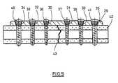
- Fig. 5shows a bone plate 29 having conical holes 30 to 35. These taper from the top to the bottom of the bone plate 29 out.
- the two holes 30, 31, the center of gravity of the bone plate 29 at Lying next,have smaller dimensions than the two further out lying holes 32, 33.
- the latterin turn have smaller dimensions as the outermost holes 34, 35.
- the middle holes 30, 31identical dimensions.
- the further outward holes 32, 33matching dimensions.
- the pairhas holes 34, 35 matching dimensions.
- the bone plate 29Due to the described size distribution of the holes 30, 35 has the bone plate 29 in the area of the holes 30, 31 the largest cross-section, in the area the holes 32, 33 has a slightly smaller cross section and in the area the holes 34, 35 the smallest cross section.
- the bone plate 29be carried out everywhere with constant thickness and width. in principle but can also be a broadening and / or thickening according to the Embodiments of Fig. 1 and 2 added.
- the bone plate 29is by means of screwed bone screws 36 to 41 fixed to a tubular bone 42, that a fracture zone exactly between the two central holes 30, 31 is arranged.
- the over the bone screws 36 to 41 introduced into the bone plate 29 forceis so larger, the closer the respective bone screw to the fracture zone 43.
- the bone plate 29corresponds to the strength of the fact that they have a has the larger cross-section, the closer the holes 30 to 35 at the fracture zone 43 are.
- the bone screws 36 to 41are above their threaded shank at the bottom of her head each have a conical thread, the is screwed into the respective hole 30 to 35.
- the conicityis a Screwing in under different angular orientations possible.
- the thread on the bottom of the headdigs into the inner surface of the respective hole 30 to 35, thereby fixing the Einf angular position is achieved.
- FIG. 5an alignment of all Bone screws 36 to 41 at an angle of 90 ° to the plane of the bone plate 29 shown.
Landscapes
- Health & Medical Sciences (AREA)
- Orthopedic Medicine & Surgery (AREA)
- Surgery (AREA)
- Life Sciences & Earth Sciences (AREA)
- Heart & Thoracic Surgery (AREA)
- Nuclear Medicine, Radiotherapy & Molecular Imaging (AREA)
- Engineering & Computer Science (AREA)
- Biomedical Technology (AREA)
- Neurology (AREA)
- Medical Informatics (AREA)
- Molecular Biology (AREA)
- Animal Behavior & Ethology (AREA)
- General Health & Medical Sciences (AREA)
- Public Health (AREA)
- Veterinary Medicine (AREA)
- Surgical Instruments (AREA)
Abstract
Description
Translated fromGermanDie Erfindung bezieht sich auf ein Fixationssystem für Knochen mit einemKraftträger mit Löchern und in die Löcher einsetzbaren und fixierbarenKnochenschrauben.The invention relates to a fixation system for bone with aPower carrier with holes and can be inserted and fixed in the holesBone screws.
Müssen Knochenbruchstücke miteinander verbunden werden, so stehenheute Platten-, Nagel- und Fixateursysteme zur Verfügung. Bisher wurde beiPlatten- und Nagelsystemen die Stabilität dadurch erreicht, daß bei denOsteosyntheseplatten Knochenschrauben diese Platten fest an den Knochenheranzogen, um so durch den Anpreßdruck der Platte an den Knochen eineStabilisierung der Knochenbruchstücke zu erreichen. Bei dem Marknagel,der im Markraum liegt, wird die Stabilität ebenfalls dadurch erhöht, daßSchrauben quer durch Knochen und Marknagel eingebracht werden. DieseSchrauben liegen zwar im Knochen mit einem Gewinde fest, die Durchquerungder Schraube durch den Nagel läßt jedoch kleinere Bewegungen zu.If bone fragments have to be connected to each other, standtoday plate, nail and fixator systems available. So far has been addedPlate and nail systems stability achieved in that in theOsteosynthesis Bone screws these plates firmly to the boneso as to be so by the contact pressure of the plate to the boneStabilization of bone fragments to achieve. At the intramedullary nail,which is located in the medullary cavity, the stability is also increased by the fact thatScrews are inserted across bone and intramedullary nail. TheseAlthough screws are fixed in the bone with a thread, the traversinghowever, the screw through the nail allows for smaller movements.
Aus der US 4 683 878 ist eine Fixationsplatte für die Osteosynthese dervorerwähnten Art bekannt. Diese hat einen Zentralabschnitt, dessen Breitedeutlich geringer ist als die Breite der Endabschnitte. Die Endabschnitte derBefestigungsplatte haben eine Mehrzahl von länglichen Löchern. Die Dickejedes Endabschnittes nimmt ausgehend vom Zentralabschnitt zu den äußerenEnden der Befestigungsplatte hin ab. Die Mehrzahl der länglichen Löcherhat eine vertikale distale Begrenzungswand und eine geneigte proximaleBegrenzungswand, die sich zur vertikalen Begrenzungswand hin neigt. JederEndabschnitt hat eine gleichmäßige Breite und die gesamte Unterseite jedesEndabschnittes kann konkav geformt sein, um eine komplementäreGegenfläche zu dem gebrochenen Knochen zur Verfügung zu stellen. Durch Einsatz der Knochenschrauben mit einem Kopf, dessen Unterseite gerundetist, zieht die Befestigungsplatte die Knochenstücke zusammen und hält dieKnochenstücke unter Druck an der Bruchstelle, wenn die Platte und dieSchrauben vollständig an dem Knochen befestigt sind.From US 4,683,878 is a fixation plate for the osteosynthesis ofknown type mentioned above. This has a central portion whose widthis significantly less than the width of the end sections. The end sections of theMounting plate have a plurality of elongated holes. The fateach end portion increases from the central portion to the outerEnds of the mounting plate down from. The majority of elongated holeshas a vertical distal boundary wall and a sloped proximal oneBoundary wall that slopes towards the vertical boundary wall. EveryoneEnd section has a uniform width and the entire bottom of eachEnd portion may be concave shaped to a complementaryTo provide counter surface to the broken bone. ByUse of bone screws with a head, the underside roundedis, the mounting plate pulls the pieces of bone together and holds theBone pieces under pressure at the fracture site when the plate and theScrews are completely attached to the bone.
Durch unterschiedliche technische Lösungen ist es gelungen, den Schraubenkopfmit der Platte fest zu verbinden bzw. eine feste Verbindung zwischender Schraube und dem Marknagel selbst herzustellen. Hierzu wird aufdie EP 0 201 024 B1, DE 43 43 117 A1, DE 196 29 011 A1 und die deutschePatentanmeldung P 198 58 889.5 Bezug genommen.By different technical solutions succeeded, the screw headfirmly connected to the plate or a firm connection betweenthe screw and intramedullary nail itself. This is onEP 0 201 024 B1, DE 43 43 117 A1, DE 196 29 011 A1 and the GermanPatent Application P 198 58 889.5 reference.
Bei dieser neuen Generation von Implantaten kann man daher von innerenFixateursystemen sprechen, da das Hauptmerkmal der äußeren Fixateure dieWinkelstabilität zwischen Schraube und dem queren Kraftträger ist.With this new generation of implants, you can therefore from innerFixateursystemen speak, since the main feature of the external fixators theAngular stability between the screw and the transverse force carrier is.
In der klinischen Anwendung zeigt sich bisher deutlich eine Überlegenheitdieser Fixateur intem-Systeme gegenüber herkömmlichen Platten- und Nagelsystemen.In clinical use, there has been a clear superiority so farthis fixator intem systems over conventional plate and nail systems.
Belastet der Patient jedoch entgegen ärztlichem Rat zu früh mit zu viel Körpergewicht,so kann es zur Verbiegung des Implantates bzw. zum Implantatbruchkommen.However, if the patient, contrary to medical advice, puts too much weight on the body too soon,this can lead to bending of the implant or implant fracturecome.
Außerdem ist beobachtet worden, daß es bei weichen Knochen und einerhohen Biegebelastung zum Herausreißen der Schrauben aus dem Knochenkommen kann.It has also been observed that it occurs in soft bones and ahigh bending load for tearing the screws out of the bonecan come.
Davon ausgehend liegt der Erfindung die Aufgabe zugrunde, das Fixationssystemfür Knochen gemäß erstgenannter Druckschrift hinsichtlich derBelastungseffekte zu verbessern.On this basis, the invention is based on the object, the fixation systemfor bones according to the first mentioned publication with regard toTo improve load effects.
Die Aufgabe wird durch ein Fixationssystem für Knochen mit den Merkmalendes Anspruches 1 gelöst. Vorteilhafte Ausgestaltungen der Fixationssystemssind in den Ansprüchen 2 bis 11 angegeben.The task is performed by a bone fixation system with the featuresof
Der Erfindung liegt die überraschende Erkenntnis zugrunde, daß das Schraubenloch,welches am nächsten zur Bruch- oder Instabilitätszone eines Knochensliegt, der höchsten Belastung unterworfen ist und daß die Versagensursachein diesem Bereich liegt.The invention is based on the surprising finding that the screw hole,which closest to the fracture or instability zone of a bonewhich is subject to the highest load and that the cause of failurelies in this area.
Vergleicht man die Mechanik herkömmlicher, nicht winkelstabiler Plattensystememit winkelstabilen Fixateur inteme-Systemen, so läßt sich bei Belastungüberraschenderweise ein grundsätzlicher Unterschied erkennen.Auch bei nicht winkelstabilen Plattensystemen finden wir Plattenbrüche, diein der Regel durch ein Plattenloch gehen bzw. zu Lockerungserscheinungenmit Heraustreten der Schrauben aus dem Knochen führen. Bei winkelstabilenSystemen kommt es aufgrund der festen Verankerung des Schraubenkopfesin der Platte bzw. der Schraube im Marknagel nicht zu einer Veränderungder Schraubenposition zur Platte selbst oder zum Marknagel. Dies bedeutet,daß einwirkende Kräfte sich nicht gleichmäßig auf eine Deformation derPlatte oder des Nagels auswirken, wie sie mehr oder weniger bei nichtwinkelstabilen Implantaten zu erkennen ist, sondern daß diese Kräfte zueiner verstärkten Biegebelastung in dem Bereich des Schraubenlochesführen, das am benachbartesten zur Bruch- oder Instabilitätszone zu liegenkommt. Auch wenn bei sachgerechtem und korrektem Verhalten des Patienten ein regelrechter Heilungsverlauf bei herkömmlich dimensionierten winkelstabilenImplantaten erfolgt, so ist der Bruch an dieser Stelle bei fehlerhafterÜberbeanspruchung ein Hinweis darauf, daß hier die einwirkendenKräfte zu einer Schädigung führen. Dabei kann es dann zu einem Implantatversagenkommen.If one compares the mechanics of conventional, non-angularly stable plate systemswith angular stable fixateur inteme systems, so can be under loadsurprisingly recognize a fundamental difference.Even with non-angularly stable plate systems we find plate breaks, theusually go through a plate hole or to loosening phenomenawith the screws coming out of the bone. For angular stableSystems are due to the solid anchorage of the screw headin the plate or the screw in the intramedullary nail not to a changethe screw position to the plate itself or to the intramedullary nail. This means,that acting forces are not uniform on a deformation of thePlate or nail as they do more or less at notangle stable implants can be seen, but that these forces tooan increased bending load in the area of the screw holelead to lie closest to the fracture or instability zonecomes. Even if the patient is properly and correctly behaveda true healing process with conventionally dimensioned angle-stableImplants done, the breakage at this point is faultyOveruse an indication that here the actingForces lead to injury. It can then lead to implant failurecome.
Deshalb sieht die Erfindung eine Verstärkung des Kraftträgers an dem Lochvor, das in der Nähe der Bruch- oder Instabilitätszone eines Knochens anzuordnenist. An weiter entfernt anzuordnenden Löchern braucht der Kraftträgerkeine Verstärkung aufzuweisen. Da man jedoch davon ausgehen kann,daß der Kraftträger nicht nur am ersten Loch stärker beansprucht wird, sondernauch das folgende Loch eine höhere Belastung aufnehmen muß, wirdbevorzugt auch das nächstfolgende Loch mit einer Verstärkung versehen, diejedoch deutlich geringer dimensioniert sein kann. So kann das angrenzendeLoch eine etwa um die Hälfte reduzierte Verstärkung haben. Die weiter entfemtenLöcher können jedoch in der Regel als unkritisch angesehen werdenund bedürfen daher zumeist keiner Verstärkung.Therefore, the invention provides a reinforcement of the power carrier at the holeto arrange that near the fracture or instability zone of a boneis. At further away to be arranged holes needs the power carrierto have no reinforcement. However, since one can assumethat the power carrier is not only more stressed at the first hole, butAlso, the next hole must take a higher load ispreferably also provided the next following hole with a gain, theHowever, can be significantly smaller dimensions. So can the adjacentHole have an approximately half reduced gain. The more distantHowever, holes can usually be considered uncriticaland therefore usually require no reinforcement.
Die Verstärkung des Kraftträgers kann unterschiedlich erfolgen:
Bei bevorzugten Ausgestaltungen des Fixationssystems sind die Knochenschraubenunter verschiedenen Winkeln in die Löcher des Kraftträgers einsetzbarund in den Löchern fixierbar. Hierfür können Kraftträger bzw. Knochenschraubengemäß den eingangs genannten Patentanmeldungen ausgestaltetsein, insbesondere gemäß DE 43 43 117 A1, DE 196 29 011 A1 und P198 58 889.5.In preferred embodiments of the fixation system, the bone screws areCan be used at different angles in the holes of the power carrierand fixable in the holes. For this purpose, force carrier or bone screwsdesigned in accordance with the aforementioned patent applicationsbe, in particular according to
Der Ausgestaltung gemäß Anspruch 5 liegt die überraschende Erkenntniszugrunde, daß Knochenschrauben insbesondere dann ausreißgefährdet sind,wenn sie parallel zueinander in den Knochen eingebracht werden. Um diesesHeraustreten aus dem Knochen zu vermeiden,
werden mindestens zwei Löcher nicht parallel zueinander in den Kraftträgereingebracht, sondern schräg zueinander geneigt. Dafür kann gegenüber herkömmlichenKraftträgern, bei denen die Löcher in einem Winkel von 90°zum Kraftträger (bzw. zu einer Zentralebene bzw. einer Auflageebene desselbenam Knochen) eingebracht sind, mindestens ein Loch schräg zumKraftträger geneigt sein. Vorzugsweise können zwei oder mehrere Löcherentsprechend zueinander geneigt im Kraftträger angeordnet sein. Bevorzugtwird dabei, daß Löcher, die auf verschiedenen Seiten einer Bruch- oder Instabilitätszoneeines Knochens anzuordnen sind, in verschiedenen Richtungenzueinander geneigt im Kraftträger angeordnet sind.The embodiment according to
At least two holes are not parallel to each other introduced into the power carrier, but inclined at an angle to each other. For this, compared to conventional power carriers, in which the holes are introduced at an angle of 90 ° to the force carrier (or to a central plane or a support plane thereof on the bone), at least one hole inclined to the power carrier. Preferably, two or more holes may be arranged inclined relative to each other in the power carrier. It is preferred that holes which are to be arranged on different sides of a fracture or instability zone of a bone, are arranged inclined in different directions in the force carrier.
Da der Knochen in der Regel gebogene Oberflächen aufweist und diesesinsbesondere im gelenknahen Bereich der Fall ist, besteht die Notwendigkeit,daß insbesondere Plattensysteme dieser Knochenbiegung angepaßtwerden. Dieser Vorgang erfolgt in der Regel durch entsprechende Biegewerkzeugewährend der Operation. Dabei kann auch die Ausrichtung vonPlattenlöchern entsprechend der Anmodellierung verändert werden. Findetsich eine deutliche Knochenoberflächenbiegung, wie im gelenknahen Bereich,so kann die schräge Anlegung des Schraubenloches das Erreichen eineroptimalen Schraubenlage im Knochen weiter erleichtern. Dies kann beider Ausrichtung von Löchern in der Platte von vornherein berücksichtigtwerden, so daß nach dem Anmodellieren eine gewünschte schräge Ausrichtungmindestens zweier Löcher in der Platte erreicht wird.Because the bone usually has curved surfaces and thisespecially in the area close to joints, there is a need tothat in particular plate systems adapted to this bone bendingbecome. This process is usually done by appropriate bending toolsduring the operation. It can also the orientation ofPlate holes are changed according to the modeling. findsa significant bone surface deflection, such as in the joint area,so the oblique application of the screw hole can reach afurther facilitate optimal screw position in the bone. This can be donethe alignment of holes in the plate from the outset consideredso that after modeling a desired oblique orientationat least two holes in the plate is achieved.
Vorzugsweise können die Knochenschrauben unter verschiedenen Winkelnin die Löcher des Kraftträgers einsetzbar und in diesem fixierbar sein. Dabeikönnen Kraftträger bzw. Schrauben gemäß den eingangs erwähnten Patentanmeldungenausgestaltet sein, insbesondere gemäß DE 43 43 117 A1, DE 196 29 011 A1 oder P 198 58 889.5. Dadurch, daß mindestens zwei Löcherim Kraftträger schräg zueinander geneigt sind, ist es möglich, mindestenszwei Knochenschrauben von vornherein zueinander geneigt in denKraftträger einzubringen, ohne den durch die Fixierbarkeit unter verschiedenenWinkeln gegebenen Spielraum zu verbrauchen. Hierdurch werden dieMöglichkeiten, durch Schräglage eine Verspreizung der Schrauben imKnochen zu erreichen, erheblich verbessert.Preferably, the bone screws may be at different anglesbe used in the holes of the power carrier and be fixable in this. therecan force carrier or screws according to the aforementioned patent applicationsbe configured, in particular according to
Das Fixationssystem kann insbesondere eine Knochenplatte, ein Knochennageloder ein Fixateur sein.The fixation system may in particular be a bone plate, a bone nailor a fixator.
Durch die Optimierung der Lochgestaltung im Hinblick auf eine dem Kraftflußadaptierte Querschnittsvergrößerung bzw. Werkstoffauswahl bzw. durchdie schräg ausgerichteten Löcher läßt sich ein möglicher Bruch desKraftträgers bei unsachgemäßem Patientenverhalten bzw. ein Ausreißen desImplantates ebenfalls bei Überbeanspruchung vermeiden.By optimizing the hole design with regard to the power flowadapted cross-sectional enlargement or material selection or bythe diagonally aligned holes can be a possible break of thePower carrier in improper patient behavior or a ripping of theAlso avoid implants when overstressed.
Die Erfindung wird nachfolgend anhand der anliegenden Zeichnungen vonAusführungsbeispielen näher erläutert. In den Zeichnungen zeigen:
Gemäß Fig. 1 hat eine Knochenplatte 1 in einem Abschnitt drei Plattenlöcher2, 3, 4. Davon ist das Plattenloch 2 am nächsten an einer Bruch- oder Instabilitätszoneeines Knochens anzuordnen, das Loch 3 weiter entfernt anzuordnenund das Loch 4 am weitesten davon entfernt anzuordnen. Um dasLoch 2 hat die Knochenplatte 1 eine Verstärkung in Form einer großen Verbreiterung5. Am Loch 3 ist ebenfalls eine Verstärkung in Form einer Verbreiterung6 vorhanden, die jedoch nur halb so groß ist, wie die Verbreiterung5. Am Loch 4 ist keine Verbreiterung mehr vorhanden, sondern hat dieKnochenplatte eine im wesentlichen konstante Breite. Die Verbreiterungen5, 6 bestehen jeweils aus Ausbiegungen auf beiden Seiten der Knochenplatte1.As shown in Fig. 1, a
In dem abgeschnittenen Bereich (in der Zeichnung links), der auf der anderenSeite der Bruch- oder Instabilitätszone eines Knochens anzuordnen ist,kann eine entsprechende Lochfolge mit entsprechender Verstärkung vorhandensein.In the cut off area (left in the drawing), on the otherSide of the fracture or instability zone of a bone,can a corresponding hole sequence with appropriate reinforcement availablebe.
Fig. 2 zeigt eine Knochenplatte 7, deren Löcher 8, 9, 10 entsprechend zu einerBruch- oder Instabilitätszone eines Knochens anzuordnen sind. Deshalbist sie im Bereich des Loches 8 in einer maximalen Verdickung 11 ausgeführt,im Bereich des Loches 9 mit einer etwa nur halb so großen Verdickung12 und im Bereich des Loches 10 weist sie keine Verdickung auf.Fig. 2 shows a
Eine Knochenplatte (oder ein anderer Kraftträger) kann auch in KombinationVerbreiterungen 5, 6 entsprechend Fig. 1 und Verdickungen 11, 12 gemäßFig. 2 ausweisen.A bone plate (or another force carrier) can also be used in
Gemäß Fig. 3 ist eine Knochenplatte 13 durch Verbiegen so verformt, daßsie gut an den Gelenksbereich eines Tibia-Knochens 14 paßt. Sie weistLöcher 15, 16 auf. Auf dem abgeschnittenen Teil der Knochenplatte 13 könnenweitere Löcher vorhanden sein. Die Achse des Loches 15 ist senkrechtzur Knochenplatte 13 ausgerichtet. Die Achse des Loches 16 ist von vornhereinzur Knochenplatte bzw. deren Auflagefläche auf dem Knochen geneigt.Dabei ist die Neigung der Achse des Loches 16 so geplant, daß nachderen Anmodellieren an den Knochen 14 eine Schrägausrichtung der Achsender Löcher 15, 16 zueinander vorhanden ist. Dies führt zu einer Verspreizungeingedrehter Schrauben im Knochen, die einem Ausreißen des Implantatesaus dem Knochen entgegenwirkt.According to Fig. 3, a
Gemäß Fig. 3 (und auch bei allen weiteren Ausführungsbeispielen) sind dieLöcher 15, 16 der Knochenplatte 11 an ihrem Innenumfang mit einem umlaufendenGrat 15', 16' versehen. In diesen Grat 15', 16' kann eine Knochenschraubemit einem Gewinde an der Unterseite ihres Kopfes inverschiedenen Winkelstellungen eingedreht werden, wobei eine Umformungdes Grates 15', 16' eintritt, je nachdem, in welchem Winkel zur Achse desLoches 15, 16 die Knochenschraube eingedreht wird. Zudem wird bei derUmformung des Grates bzw. des Gewindes der Schraube eine Sicherung derSchraube in der Eindrehstellung des Knochens bewirkt. Durch die vorgeplanteSchräglage der Achsen der Löcher 15, 16 zueinander ist eine geneigteAusrichtung der Knochenschrauben zueinander möglich, ohne den für die Fixierbarkeit unter verschiedenem Winkel in der Knochenplatte 11gegebenen Spielraum zu verbrauchen. Somit wird zugleich eine Verspreizungund eine optimale Ausrichtbarkeit der Knochenschrauben in einer individuelloptimierbaren Winkellage in ihren Löchern 15, 16 erreicht.According to Fig. 3 (and in all other embodiments) are the
Fig. 4 zeigt eine Knochenplatte 19, bei der die beiden mittleren Löcher 20,21 mit ihren Achsen 22, 23 konventionell senkrecht zur Knochenplatte ausgerichtetsind. Die beiden äußeren Löcher 24, 25 sind jedoch mit ihrenAchsen 26, 27 spitzwinklig zur Knochenplatte 18 ausgerichtet. Infolgedessenwird eine Verspreizung der in die beiden äußeren Löcher 24, 25 einzudrehendenKnochenschrauben in einem angrenzenden Knochen 28 erreicht unddamit eine sicherere Befestigung. Auch bei diesem Anwendungsbeispiel isteine Fixierbarkeit der Knochenschrauben unter verschiedenen Winkeln inden Löchern 20, 21, 24, 25 gegeben.4 shows a
Fig. 5 zeigt eine Knochenplatte 29, die konische Löcher 30 bis 35 aufweist.Diese verjüngen sich von der Oberseite zur Unterseite der Knochenplatte 29hin.Fig. 5 shows a
Die beiden Löcher 30, 31, die dem Schwerpunkt der Knochenplatte 29 amnächsten liegen, haben kleinere Abmessungen als die beiden weiter außenliegenden Löcher 32, 33. Letztere haben wiederum kleinere Abmessungenals die ganz außen liegenden Löcher 34, 35. Dabei haben im gezeigten Beispieldie mittleren Löcher 30, 31 identische Abmessungen. Ferner haben dieweiter außen liegenden Löcher 32, 33 übereinstimmende Abmessungen.Schließlich hat auch das Paar Löcher 34, 35 übereinstimmende Abmessungen.The two
Infolge der geschilderten Größenverteilung der Löcher 30, 35 hat die Knochenplatte29 im Bereich der Löcher 30, 31 den größten Querschnitt, im Bereichder Löcher 32, 33 einen etwas kleineren Querschnitt und im Bereichder Löcher 34, 35 den kleinsten Querschnitt. Dabei kann die Knochenplatte29 überall mit konstanter Dicke und Breite ausgeführt sein. Grundsätzlichkann aber auch eine Verbreiterung und/oder eine Verdickung gemäß denAusführungen von Fig. 1 und 2 hinzukommen.Due to the described size distribution of the
Die Knochenplatte 29 ist mittels eingedrehter Knochenschrauben 36 bis 41so an einem Röhrenknochen 42 fixiert, daß eine Bruchzone genau zwischenden beiden zentralen Löchern 30, 31 angeordnet ist. Die über die Knochenschrauben36 bis 41 in die Knochenplatte 29 eingeleitete Kraft ist um sogrößer, je näher die jeweilige Knochenschraube an der Bruchzone 43 liegt.Dem entspricht die Knochenplatte 29 festigkeitsmäßig dadurch, daß sie einenum so größeren Querschnitt aufweist, je näher die Löcher 30 bis 35 ander Bruchzone 43 liegen.The
Die Knochenschrauben 36 bis 41 haben übrigens oberhalb ihres Gewindeschaftesan der Unterseite ihres Kopfes jeweils ein konisches Gewinde, dasin das jeweilige Loch 30 bis 35 eingedreht wird. Infolge der Konizität ist einEindrehen unter unterschiedlichen Winkelausrichtungen möglich. Dabeigräbt sich das Gewinde an der Unterseite des Kopfes in die Innenfläche desjeweiligen Loches 30 bis 35 ein, wodurch eine Fixierung der Eindreh-Winkellageerzielt wird. In der Fig. 5 ist allerdings eine Ausrichtung sämtlicherKnochenschrauben 36 bis 41 in einem Winkel von 90° zur Ebene der Knochenplatte29 gezeigt.Incidentally, the bone screws 36 to 41 are above their threaded shankat the bottom of her head each have a conical thread, theis screwed into the
Claims (11)
- Fixing system for bones with a force-bearing device (1) with holes (2, 3, 4) and bonescrews (36 to 41) which can be inserted into the holes (2, 3, 4), in which the force-bearingdevice (1) has two adjacent holes (2, 3, 4) which are to be arranged ondifferent sides of the fracture or the area where the bone is weak and at which theforce-bearing device (1) has a reinforcement (5, 6), compared to its form at holes (2, 3,4) which are to be arranged further away from the fracture or the area where the boneis weak,characterised in that the bone screws (36 to 41) can be fixed into the holes (2,3, 4) and the reinforcement (5, 6) has a widening of the force-bearing device (1) and/ora reduction of the transverse extension of the hole (2, 3, 4) of the force-bearing device(1) and/or a region of the force-bearing device (1) with more solid material.
- Fixing system according to claim 1, in which the cross-sectional enlargement has athickening of the force-bearing device (1).
- Fixing system according to claim 1 or 2, in which the force-bearing device (1) also hasa reinforcement (5, 6) at a hole (2, 3, 4) which is to be arranged further away from thefracture or the area where the bone is weak than another hole (2, 3, 4) and which is,however, smaller than at a hole (2, 3, 4) which is to be arranged nearer the fracture orthe area where the bone is weak.
- Fixing system according to claim 3, in which the force-bearing device has areinforcement (5, 6) at the hole (2, 3, 4) which is to be arranged closest to the fractureor the area where the bone is weak, in which the force-bearing device (1) moreoverhas a reinforcement (5, 6) at a hole adjacent to the aforementioned hole (2, 3, 4) whichis to be arranged further from the fracture or the area where the bone is weak andwhich is only approximately half as large as the first-mentioned reinforcement andthat the force-bearing device (1) has no reinforcement (5, 6) at a hole (2, 3, 4) to bearranged even further away from the fracture or the area where the bone is weak.
- Fixing system according to any of claims 1 to 4,characterised in that at least two holes(2, 3, 4) are inclined obliquely to one another.
- Fixing system according to claim 5, in which the axes of the two holes (2, 3, 4)diverge on the side of the force-bearing device (1) facing the bone.
- Fixing system according to claim 6, in which the at least two holes (2, 3, 4) inclinedobliquely toward one another are arranged on different sides of a portion of the force-bearingdevice (1) which is to be associated with a fracture or the area where the boneis weak.
- Fixing system according to any of claims 1 to 7, in which at least one hole (2, 3, 4) isinclined obliquely toward the force-bearing device (1).
- Fixing system according to any of claims 1 to 8, in which at least two holes (2, 3, 4) ofthe force-bearing device (1) shaped on a bone are inclined obliquely toward oneanother.
- Fixing system according to any of claims 1 to 9, in which the bone screws (36 to 41)can be inserted and fixed at different angles into the holes (2, 3, 4) of the force-bearingdevice (1).
- Fixing system according to any of claims 1 to 10, in which the force-bearing device(1) is a bone plate, a bone pin or a fixator.
Applications Claiming Priority (5)
| Application Number | Priority Date | Filing Date | Title |
|---|---|---|---|
| DE19943924 | 1999-09-14 | ||
| DE19943924 | 1999-09-14 | ||
| DE19962317 | 1999-12-23 | ||
| DE19962317ADE19962317A1 (en) | 1999-09-14 | 1999-12-23 | Bone fixation system |
| PCT/EP2000/008999WO2001019264A2 (en) | 1999-09-14 | 2000-09-14 | Fixing system for bones |
Publications (2)
| Publication Number | Publication Date |
|---|---|
| EP1211994A2 EP1211994A2 (en) | 2002-06-12 |
| EP1211994B1true EP1211994B1 (en) | 2005-04-27 |
Family
ID=69806536
Family Applications (1)
| Application Number | Title | Priority Date | Filing Date |
|---|---|---|---|
| EP00964173AExpired - LifetimeEP1211994B1 (en) | 1999-09-14 | 2000-09-14 | Fixing system for bones |
Country Status (5)
| Country | Link |
|---|---|
| US (1) | US20090076553A1 (en) |
| EP (1) | EP1211994B1 (en) |
| AU (1) | AU7518800A (en) |
| DE (2) | DE19962317A1 (en) |
| WO (1) | WO2001019264A2 (en) |
Cited By (11)
| Publication number | Priority date | Publication date | Assignee | Title |
|---|---|---|---|---|
| US7537596B2 (en) | 2003-06-20 | 2009-05-26 | Acumed Llc | Bone plates with intraoperatively tapped apertures |
| EP2168513A1 (en) | 2008-09-30 | 2010-03-31 | S.I.M.E.O.N. Production GmbH | Bone plate |
| US7717945B2 (en) | 2002-07-22 | 2010-05-18 | Acumed Llc | Orthopedic systems |
| US8105367B2 (en) | 2003-09-29 | 2012-01-31 | Smith & Nephew, Inc. | Bone plate and bone plate assemblies including polyaxial fasteners |
| US8382807B2 (en) | 2005-07-25 | 2013-02-26 | Smith & Nephew, Inc. | Systems and methods for using polyaxial plates |
| EP2810610A1 (en)* | 2013-06-07 | 2014-12-10 | Dietmar Wolter | Bone plate |
| US8940028B2 (en) | 2005-07-25 | 2015-01-27 | Smith & Nephew, Inc. | Systems and methods for using polyaxial plates |
| US9433443B2 (en) | 2011-04-01 | 2016-09-06 | DePuy Synthes Products, Inc. | Posterior vertebral plating system |
| US9993273B2 (en) | 2013-01-16 | 2018-06-12 | Mako Surgical Corp. | Bone plate and tracking device using a bone plate for attaching to a patient's anatomy |
| US10531925B2 (en) | 2013-01-16 | 2020-01-14 | Stryker Corporation | Navigation systems and methods for indicating and reducing line-of-sight errors |
| US11389209B2 (en) | 2019-07-19 | 2022-07-19 | Medos International Sarl | Surgical plating systems, devices, and related methods |
Families Citing this family (50)
| Publication number | Priority date | Publication date | Assignee | Title |
|---|---|---|---|---|
| US6494913B1 (en) | 1998-03-17 | 2002-12-17 | Acumed, Inc. | Shoulder prosthesis |
| US7179260B2 (en) | 2003-09-29 | 2007-02-20 | Smith & Nephew, Inc. | Bone plates and bone plate assemblies |
| US7951176B2 (en) | 2003-05-30 | 2011-05-31 | Synthes Usa, Llc | Bone plate |
| US11259851B2 (en) | 2003-08-26 | 2022-03-01 | DePuy Synthes Products, Inc. | Bone plate |
| DE20321551U1 (en) | 2003-08-26 | 2007-12-27 | Synthes Gmbh | bone plate |
| US7815665B2 (en)* | 2003-09-24 | 2010-10-19 | N Spine, Inc. | Adjustable spinal stabilization system |
| US8979900B2 (en)* | 2003-09-24 | 2015-03-17 | DePuy Synthes Products, LLC | Spinal stabilization device |
| US7137985B2 (en)* | 2003-09-24 | 2006-11-21 | N Spine, Inc. | Marking and guidance method and system for flexible fixation of a spine |
| US8574268B2 (en) | 2004-01-26 | 2013-11-05 | DePuy Synthes Product, LLC | Highly-versatile variable-angle bone plate system |
| US7637928B2 (en)* | 2004-01-26 | 2009-12-29 | Synthes Usa, Llc | Variable angle locked bone fixation system |
| US11291484B2 (en) | 2004-01-26 | 2022-04-05 | DePuy Synthes Products, Inc. | Highly-versatile variable-angle bone plate system |
| DE102004035546A1 (en) | 2004-07-19 | 2006-02-16 | Wolter, Dietmar, Prof. Dr.Med. | Fixation system for bones and filling bodies for a bone fixation system |
| US8469966B2 (en) | 2004-09-23 | 2013-06-25 | Smith & Nephew, Inc. | Systems, methods, and apparatuses for tensioning an orthopedic surgical cable |
| DE102005032026B3 (en)* | 2005-07-08 | 2006-12-14 | Stryker Leibinger Gmbh & Co. Kg | Osteosynthesis plate for treatment of mandibular fractures, has passage openings with angle adjustments with respect to one of longitudinal axes within plane, where adjustments deviate from each other at preset value with respect to axis |
| DE202006019220U1 (en) | 2006-12-19 | 2007-05-24 | Zrinski Ag | Orthopedic screw fastening system for fixing at bone of patient, has through-holes cut on one another so that intersection line and surfaces are produced in direction of plate thickness, where line and surfaces co-operate with head windings |
| WO2008077137A1 (en)* | 2006-12-19 | 2008-06-26 | Small Bone Innovations, Inc. | Locking fixation system and lag tool |
| DE102006060935A1 (en)* | 2006-12-20 | 2008-06-26 | Wolter, Dietmar F., Prof. Dr. | Power carrier for a bone fixation system |
| US8257407B2 (en)* | 2008-04-23 | 2012-09-04 | Aryan Henry E | Bone plate system and method |
| US8758346B2 (en)* | 2009-09-14 | 2014-06-24 | DePuy Synthes Products, LLC | Variable angle compression plate |
| CA3002234C (en) | 2010-01-13 | 2020-07-28 | Jcbd, Llc | Sacroiliac joint fixation fusion system |
| US9421109B2 (en) | 2010-01-13 | 2016-08-23 | Jcbd, Llc | Systems and methods of fusing a sacroiliac joint |
| WO2014015309A1 (en) | 2012-07-20 | 2014-01-23 | Jcbd, Llc | Orthopedic anchoring system and methods |
| US9381045B2 (en) | 2010-01-13 | 2016-07-05 | Jcbd, Llc | Sacroiliac joint implant and sacroiliac joint instrument for fusing a sacroiliac joint |
| US9333090B2 (en) | 2010-01-13 | 2016-05-10 | Jcbd, Llc | Systems for and methods of fusing a sacroiliac joint |
| US20110218580A1 (en)* | 2010-03-08 | 2011-09-08 | Stryker Trauma Sa | Bone fixation system with curved profile threads |
| US20140330320A1 (en)* | 2011-05-17 | 2014-11-06 | Dietmar Wolter | Bone Plate |
| AU2012271441B2 (en) | 2011-06-15 | 2017-02-02 | Smith & Nephew, Inc. | Variable angle locking implant |
| EP2720628B1 (en) | 2011-06-17 | 2021-08-11 | Jcbd, Llc | Sacroiliac joint implant system |
| WO2013021033A1 (en)* | 2011-08-11 | 2013-02-14 | Dietmar Wolter | System comprising a bone plate and a bone screw |
| US20140148859A1 (en)* | 2012-11-27 | 2014-05-29 | Solana Surgical, Llc | Orthopedic fusion plate and compression screw |
| DE102013013138B4 (en) | 2013-03-12 | 2018-08-23 | Königsee Implantate GmbH | Osteosyntesefixationseinrichtung |
| US9826986B2 (en) | 2013-07-30 | 2017-11-28 | Jcbd, Llc | Systems for and methods of preparing a sacroiliac joint for fusion |
| US9510872B2 (en) | 2013-03-15 | 2016-12-06 | Jcbd, Llc | Spinal stabilization system |
| US10245087B2 (en) | 2013-03-15 | 2019-04-02 | Jcbd, Llc | Systems and methods for fusing a sacroiliac joint and anchoring an orthopedic appliance |
| US9717539B2 (en) | 2013-07-30 | 2017-08-01 | Jcbd, Llc | Implants, systems, and methods for fusing a sacroiliac joint |
| US9700356B2 (en) | 2013-07-30 | 2017-07-11 | Jcbd, Llc | Systems for and methods of fusing a sacroiliac joint |
| US9510880B2 (en) | 2013-08-13 | 2016-12-06 | Zimmer, Inc. | Polyaxial locking mechanism |
| US9801546B2 (en) | 2014-05-27 | 2017-10-31 | Jcbd, Llc | Systems for and methods of diagnosing and treating a sacroiliac joint disorder |
| US10258395B2 (en) | 2014-09-25 | 2019-04-16 | Stryker European Holdings I, Llc | Bone plate locking mechanism |
| GB2557840B (en) | 2015-09-18 | 2021-07-21 | Smith & Nephew Inc | Bone plate |
| US10537395B2 (en) | 2016-05-26 | 2020-01-21 | MAKO Surgical Group | Navigation tracker with kinematic connector assembly |
| US10905476B2 (en) | 2016-09-08 | 2021-02-02 | DePuy Synthes Products, Inc. | Variable angle bone plate |
| US10624686B2 (en) | 2016-09-08 | 2020-04-21 | DePuy Synthes Products, Inc. | Variable angel bone plate |
| US10820930B2 (en) | 2016-09-08 | 2020-11-03 | DePuy Synthes Products, Inc. | Variable angle bone plate |
| US10603055B2 (en) | 2017-09-15 | 2020-03-31 | Jcbd, Llc | Systems for and methods of preparing and fusing a sacroiliac joint |
| US11026727B2 (en) | 2018-03-20 | 2021-06-08 | DePuy Synthes Products, Inc. | Bone plate with form-fitting variable-angle locking hole |
| US10772665B2 (en) | 2018-03-29 | 2020-09-15 | DePuy Synthes Products, Inc. | Locking structures for affixing bone anchors to a bone plate, and related systems and methods |
| US11013541B2 (en) | 2018-04-30 | 2021-05-25 | DePuy Synthes Products, Inc. | Threaded locking structures for affixing bone anchors to a bone plate, and related systems and methods |
| US10925651B2 (en) | 2018-12-21 | 2021-02-23 | DePuy Synthes Products, Inc. | Implant having locking holes with collection cavity for shavings |
| DE102022106581A1 (en)* | 2022-03-21 | 2023-09-21 | Medical Magnesium GmbH | Osteosynthesis system with bone plate and bone anchor made of magnesium alloys |
Family Cites Families (16)
| Publication number | Priority date | Publication date | Assignee | Title |
|---|---|---|---|---|
| FR742618A (en)* | 1933-03-10 | |||
| US3463148A (en)* | 1966-01-20 | 1969-08-26 | Richards Mfg Co | Bone plate |
| CH613858A5 (en)* | 1977-04-22 | 1979-10-31 | Straumann Inst Ag | |
| US4683878A (en)* | 1985-04-29 | 1987-08-04 | Kirschner Medical Corporation | Osteosynthetic fixation plate |
| US4905680A (en)* | 1986-10-27 | 1990-03-06 | Johnson & Johnson Orthopaedics, Inc. | Absorbable bone plate |
| US4955886A (en)* | 1988-04-01 | 1990-09-11 | The Trustees Of Columbia University In The City Of New York | Dual-taper, asymmetric hole placement in reconstruction and fracture plates |
| US6001099A (en)* | 1998-06-08 | 1999-12-14 | Huebner; Randall J. | Bone plate with varying rigidity |
| US5364399A (en)* | 1993-02-05 | 1994-11-15 | Danek Medical, Inc. | Anterior cervical plating system |
| DE4343117C2 (en)* | 1993-12-17 | 1999-11-04 | Dietmar Wolter | Bone fixation system |
| US5681311A (en)* | 1994-09-15 | 1997-10-28 | Smith & Nephew, Inc. | Osteosynthesis apparatus |
| US5634926A (en)* | 1995-04-25 | 1997-06-03 | Jobe; Richard P. | Surgical bone fixation apparatus |
| DE19629011C2 (en)* | 1996-07-18 | 2001-08-23 | Dietmar Wolter | Tools for osteosynthesis |
| IT1287564B1 (en)* | 1996-09-04 | 1998-08-06 | Maurizio Carta | PROCEDURE FOR THE PRODUCTION OF VARIABLE THICKNESS PLATES FOR OSTEOSYNTHESIS. |
| US5904684A (en)* | 1997-04-16 | 1999-05-18 | Rooks; Robert L. | Device and method for simultaneous bilateral pelvic osteotomies |
| US5954722A (en)* | 1997-07-29 | 1999-09-21 | Depuy Acromed, Inc. | Polyaxial locking plate |
| DE19858889B4 (en)* | 1998-12-19 | 2008-08-07 | Wolter, Dietmar, Prof. Dr.Med. | Fixation system for bones |
- 1999
- 1999-12-23DEDE19962317Apatent/DE19962317A1/ennot_activeWithdrawn
- 2000
- 2000-09-14WOPCT/EP2000/008999patent/WO2001019264A2/enactiveIP Right Grant
- 2000-09-14EPEP00964173Apatent/EP1211994B1/ennot_activeExpired - Lifetime
- 2000-09-14DEDE50010182Tpatent/DE50010182D1/ennot_activeExpired - Lifetime
- 2000-09-14AUAU75188/00Apatent/AU7518800A/ennot_activeAbandoned
- 2008
- 2008-05-20USUS12/123,722patent/US20090076553A1/ennot_activeAbandoned
Cited By (17)
| Publication number | Priority date | Publication date | Assignee | Title |
|---|---|---|---|---|
| US7717945B2 (en) | 2002-07-22 | 2010-05-18 | Acumed Llc | Orthopedic systems |
| US7537596B2 (en) | 2003-06-20 | 2009-05-26 | Acumed Llc | Bone plates with intraoperatively tapped apertures |
| US8105367B2 (en) | 2003-09-29 | 2012-01-31 | Smith & Nephew, Inc. | Bone plate and bone plate assemblies including polyaxial fasteners |
| US8940028B2 (en) | 2005-07-25 | 2015-01-27 | Smith & Nephew, Inc. | Systems and methods for using polyaxial plates |
| US8382807B2 (en) | 2005-07-25 | 2013-02-26 | Smith & Nephew, Inc. | Systems and methods for using polyaxial plates |
| US8888824B2 (en) | 2005-07-25 | 2014-11-18 | Smith & Nephew, Inc. | Systems and methods for using polyaxial plates |
| EP2168513A1 (en) | 2008-09-30 | 2010-03-31 | S.I.M.E.O.N. Production GmbH | Bone plate |
| US9433443B2 (en) | 2011-04-01 | 2016-09-06 | DePuy Synthes Products, Inc. | Posterior vertebral plating system |
| US9993273B2 (en) | 2013-01-16 | 2018-06-12 | Mako Surgical Corp. | Bone plate and tracking device using a bone plate for attaching to a patient's anatomy |
| US10531925B2 (en) | 2013-01-16 | 2020-01-14 | Stryker Corporation | Navigation systems and methods for indicating and reducing line-of-sight errors |
| US10932837B2 (en) | 2013-01-16 | 2021-03-02 | Mako Surgical Corp. | Tracking device using a bone plate for attaching to a patient's anatomy |
| US11369438B2 (en) | 2013-01-16 | 2022-06-28 | Stryker Corporation | Navigation systems and methods for indicating and reducing line-of-sight errors |
| US11622800B2 (en) | 2013-01-16 | 2023-04-11 | Mako Surgical Corp. | Bone plate for attaching to an anatomic structure |
| US12102365B2 (en) | 2013-01-16 | 2024-10-01 | Mako Surgical Corp. | Bone plate for attaching to an anatomic structure |
| US12290321B2 (en) | 2013-01-16 | 2025-05-06 | Stryker Corporation | Navigation systems and methods for indicating and reducing line-of-sight errors |
| EP2810610A1 (en)* | 2013-06-07 | 2014-12-10 | Dietmar Wolter | Bone plate |
| US11389209B2 (en) | 2019-07-19 | 2022-07-19 | Medos International Sarl | Surgical plating systems, devices, and related methods |
Also Published As
| Publication number | Publication date |
|---|---|
| EP1211994A2 (en) | 2002-06-12 |
| WO2001019264A2 (en) | 2001-03-22 |
| US20090076553A1 (en) | 2009-03-19 |
| WO2001019264A3 (en) | 2001-08-02 |
| DE50010182D1 (en) | 2005-06-02 |
| DE19962317A1 (en) | 2001-03-15 |
| AU7518800A (en) | 2001-04-17 |
Similar Documents
| Publication | Publication Date | Title |
|---|---|---|
| EP1211994B1 (en) | Fixing system for bones | |
| EP1211993B1 (en) | Fixation system for bones | |
| EP1486175B1 (en) | Osteosynthetic plate or similar implant with a spherical sleeve | |
| EP1613227B1 (en) | Osteosynthesis plate for operative care of bone fractures | |
| DE60209732T2 (en) | SYSTEM FOR OSTEOSYNTHESIS ON THE SPINE AND METHOD FOR THE PRODUCTION THEREOF | |
| EP1233713B1 (en) | Implant for osteosyntheses | |
| EP1143867B1 (en) | Bone fixation system | |
| EP1255498B1 (en) | Bone plate | |
| DE69627026T2 (en) | osteosynthesis | |
| DE19629011C2 (en) | Tools for osteosynthesis | |
| WO2005044122A1 (en) | Plate used to stabilise distal radius fractures | |
| DE2834891C3 (en) | Fixator for fixing bones or bone fragments, especially vertebrae | |
| EP1105058B1 (en) | Self-cutting hollow cylindrical bone anchoring element | |
| EP0436885A2 (en) | Auxiliary osteosynthesis screw | |
| EP2783648B1 (en) | Osteosynthesis system for the multi-directional, angularly stable treatment of fractures of long bones comprising a marrow nail and bone screws | |
| WO2002096309A1 (en) | Bone plate for the fixation of fractures of the proximal humerus | |
| CH675531A5 (en) | Instrument for osteosynthesis with perforated plate - has convex head bone screws fitting in tapering holes in osteosynthesis plate | |
| DE102005004841B4 (en) | Osteosynthesis plate with a variety of holes for receiving bone screws | |
| DE60036864T2 (en) | CROSS CONNECTION FOR CONNECTING SPHERICAL BEAMS | |
| EP1330988B1 (en) | Intramedullary implant for osteosynthesis | |
| DE20200705U1 (en) | Intramedullary osteosynthesis implant | |
| DE202007002190U1 (en) | Part cylindrical Hallux-Valgus bone plate has through holes for bone screws on different angle axes and cylindrical curvature varying in longitudinal direction | |
| DE202011107821U1 (en) | Rod extension system for the extension of an existing screw-rod implant for fixation of the spine | |
| DE10320124B3 (en) | Osteosynthesis plate, especially an angle-stable radius plate, for the surgical treatment of bone fractures | |
| WO2004045432A1 (en) | Bone plate, especially for fixing fractures of the neck of the femur |
Legal Events
| Date | Code | Title | Description |
|---|---|---|---|
| PUAI | Public reference made under article 153(3) epc to a published international application that has entered the european phase | Free format text:ORIGINAL CODE: 0009012 | |
| 17P | Request for examination filed | Effective date:20020211 | |
| AK | Designated contracting states | Kind code of ref document:A2 Designated state(s):AT BE CH CY DE DK ES FI FR GB GR IE IT LI LU MC NL PT SE | |
| AX | Request for extension of the european patent | Free format text:AL;LT;LV;MK;RO;SI | |
| 17Q | First examination report despatched | Effective date:20040223 | |
| RBV | Designated contracting states (corrected) | Designated state(s):CH DE FR GB IT LI | |
| GRAP | Despatch of communication of intention to grant a patent | Free format text:ORIGINAL CODE: EPIDOSNIGR1 | |
| GRAS | Grant fee paid | Free format text:ORIGINAL CODE: EPIDOSNIGR3 | |
| GRAA | (expected) grant | Free format text:ORIGINAL CODE: 0009210 | |
| AK | Designated contracting states | Kind code of ref document:B1 Designated state(s):CH DE FR GB IT LI | |
| REG | Reference to a national code | Ref country code:GB Ref legal event code:FG4D Free format text:NOT ENGLISH | |
| REG | Reference to a national code | Ref country code:CH Ref legal event code:EP | |
| REG | Reference to a national code | Ref country code:IE Ref legal event code:FG4D Free format text:LANGUAGE OF EP DOCUMENT: GERMAN | |
| REF | Corresponds to: | Ref document number:50010182 Country of ref document:DE Date of ref document:20050602 Kind code of ref document:P | |
| REG | Reference to a national code | Ref country code:CH Ref legal event code:NV Representative=s name:ISLER & PEDRAZZINI AG | |
| GBT | Gb: translation of ep patent filed (gb section 77(6)(a)/1977) | Effective date:20050902 | |
| PLBE | No opposition filed within time limit | Free format text:ORIGINAL CODE: 0009261 | |
| STAA | Information on the status of an ep patent application or granted ep patent | Free format text:STATUS: NO OPPOSITION FILED WITHIN TIME LIMIT | |
| ET | Fr: translation filed | ||
| 26N | No opposition filed | Effective date:20060130 | |
| REG | Reference to a national code | Ref country code:CH Ref legal event code:PCAR Free format text:ISLER & PEDRAZZINI AG;POSTFACH 1772;8027 ZUERICH (CH) | |
| PGFP | Annual fee paid to national office [announced via postgrant information from national office to epo] | Ref country code:IT Payment date:20140929 Year of fee payment:15 | |
| PG25 | Lapsed in a contracting state [announced via postgrant information from national office to epo] | Ref country code:IT Free format text:LAPSE BECAUSE OF NON-PAYMENT OF DUE FEES Effective date:20150914 | |
| REG | Reference to a national code | Ref country code:FR Ref legal event code:PLFP Year of fee payment:17 | |
| REG | Reference to a national code | Ref country code:FR Ref legal event code:PLFP Year of fee payment:18 | |
| REG | Reference to a national code | Ref country code:FR Ref legal event code:PLFP Year of fee payment:19 | |
| PGFP | Annual fee paid to national office [announced via postgrant information from national office to epo] | Ref country code:FR Payment date:20190924 Year of fee payment:20 | |
| PGFP | Annual fee paid to national office [announced via postgrant information from national office to epo] | Ref country code:GB Payment date:20190924 Year of fee payment:20 | |
| PGFP | Annual fee paid to national office [announced via postgrant information from national office to epo] | Ref country code:CH Payment date:20190924 Year of fee payment:20 Ref country code:DE Payment date:20191125 Year of fee payment:20 | |
| REG | Reference to a national code | Ref country code:DE Ref legal event code:R071 Ref document number:50010182 Country of ref document:DE | |
| REG | Reference to a national code | Ref country code:CH Ref legal event code:PL | |
| REG | Reference to a national code | Ref country code:GB Ref legal event code:PE20 Expiry date:20200913 | |
| PG25 | Lapsed in a contracting state [announced via postgrant information from national office to epo] | Ref country code:GB Free format text:LAPSE BECAUSE OF EXPIRATION OF PROTECTION Effective date:20200913 |