EP1209508B1 - Display for 3D images - Google Patents
Display for 3D imagesDownload PDFInfo
- Publication number
- EP1209508B1 EP1209508B1EP20020100151EP02100151AEP1209508B1EP 1209508 B1EP1209508 B1EP 1209508B1EP 20020100151EP20020100151EP 20020100151EP 02100151 AEP02100151 AEP 02100151AEP 1209508 B1EP1209508 B1EP 1209508B1
- Authority
- EP
- European Patent Office
- Prior art keywords
- observer
- display
- shutters
- imaging systems
- illumination
- Prior art date
- Legal status (The legal status is an assumption and is not a legal conclusion. Google has not performed a legal analysis and makes no representation as to the accuracy of the status listed.)
- Expired - Lifetime
Links
Images


Classifications
- G—PHYSICS
- G02—OPTICS
- G02B—OPTICAL ELEMENTS, SYSTEMS OR APPARATUS
- G02B27/00—Optical systems or apparatus not provided for by any of the groups G02B1/00 - G02B26/00, G02B30/00
- G02B27/0093—Optical systems or apparatus not provided for by any of the groups G02B1/00 - G02B26/00, G02B30/00 with means for monitoring data relating to the user, e.g. head-tracking, eye-tracking
- G—PHYSICS
- G02—OPTICS
- G02B—OPTICAL ELEMENTS, SYSTEMS OR APPARATUS
- G02B30/00—Optical systems or apparatus for producing three-dimensional [3D] effects, e.g. stereoscopic images
- G02B30/20—Optical systems or apparatus for producing three-dimensional [3D] effects, e.g. stereoscopic images by providing first and second parallax images to an observer's left and right eyes
- G02B30/22—Optical systems or apparatus for producing three-dimensional [3D] effects, e.g. stereoscopic images by providing first and second parallax images to an observer's left and right eyes of the stereoscopic type
- G02B30/24—Optical systems or apparatus for producing three-dimensional [3D] effects, e.g. stereoscopic images by providing first and second parallax images to an observer's left and right eyes of the stereoscopic type involving temporal multiplexing, e.g. using sequentially activated left and right shutters
- G—PHYSICS
- G02—OPTICS
- G02B—OPTICAL ELEMENTS, SYSTEMS OR APPARATUS
- G02B30/00—Optical systems or apparatus for producing three-dimensional [3D] effects, e.g. stereoscopic images
- G02B30/20—Optical systems or apparatus for producing three-dimensional [3D] effects, e.g. stereoscopic images by providing first and second parallax images to an observer's left and right eyes
- G02B30/26—Optical systems or apparatus for producing three-dimensional [3D] effects, e.g. stereoscopic images by providing first and second parallax images to an observer's left and right eyes of the autostereoscopic type
- G02B30/27—Optical systems or apparatus for producing three-dimensional [3D] effects, e.g. stereoscopic images by providing first and second parallax images to an observer's left and right eyes of the autostereoscopic type involving lenticular arrays
- G—PHYSICS
- G02—OPTICS
- G02B—OPTICAL ELEMENTS, SYSTEMS OR APPARATUS
- G02B30/00—Optical systems or apparatus for producing three-dimensional [3D] effects, e.g. stereoscopic images
- G02B30/20—Optical systems or apparatus for producing three-dimensional [3D] effects, e.g. stereoscopic images by providing first and second parallax images to an observer's left and right eyes
- G02B30/26—Optical systems or apparatus for producing three-dimensional [3D] effects, e.g. stereoscopic images by providing first and second parallax images to an observer's left and right eyes of the autostereoscopic type
- G02B30/33—Optical systems or apparatus for producing three-dimensional [3D] effects, e.g. stereoscopic images by providing first and second parallax images to an observer's left and right eyes of the autostereoscopic type involving directional light or back-light sources
- G—PHYSICS
- G02—OPTICS
- G02B—OPTICAL ELEMENTS, SYSTEMS OR APPARATUS
- G02B30/00—Optical systems or apparatus for producing three-dimensional [3D] effects, e.g. stereoscopic images
- G02B30/20—Optical systems or apparatus for producing three-dimensional [3D] effects, e.g. stereoscopic images by providing first and second parallax images to an observer's left and right eyes
- G02B30/34—Stereoscopes providing a stereoscopic pair of separated images corresponding to parallactically displaced views of the same object, e.g. 3D slide viewers
- G02B30/35—Stereoscopes providing a stereoscopic pair of separated images corresponding to parallactically displaced views of the same object, e.g. 3D slide viewers using reflective optical elements in the optical path between the images and the observer
- H—ELECTRICITY
- H04—ELECTRIC COMMUNICATION TECHNIQUE
- H04N—PICTORIAL COMMUNICATION, e.g. TELEVISION
- H04N13/00—Stereoscopic video systems; Multi-view video systems; Details thereof
- H04N13/30—Image reproducers
- H04N13/302—Image reproducers for viewing without the aid of special glasses, i.e. using autostereoscopic displays
- H04N13/305—Image reproducers for viewing without the aid of special glasses, i.e. using autostereoscopic displays using lenticular lenses, e.g. arrangements of cylindrical lenses
- H—ELECTRICITY
- H04—ELECTRIC COMMUNICATION TECHNIQUE
- H04N—PICTORIAL COMMUNICATION, e.g. TELEVISION
- H04N13/00—Stereoscopic video systems; Multi-view video systems; Details thereof
- H04N13/30—Image reproducers
- H04N13/302—Image reproducers for viewing without the aid of special glasses, i.e. using autostereoscopic displays
- H04N13/31—Image reproducers for viewing without the aid of special glasses, i.e. using autostereoscopic displays using parallax barriers
- H—ELECTRICITY
- H04—ELECTRIC COMMUNICATION TECHNIQUE
- H04N—PICTORIAL COMMUNICATION, e.g. TELEVISION
- H04N13/00—Stereoscopic video systems; Multi-view video systems; Details thereof
- H04N13/30—Image reproducers
- H04N13/302—Image reproducers for viewing without the aid of special glasses, i.e. using autostereoscopic displays
- H04N13/32—Image reproducers for viewing without the aid of special glasses, i.e. using autostereoscopic displays using arrays of controllable light sources; using moving apertures or moving light sources
- H—ELECTRICITY
- H04—ELECTRIC COMMUNICATION TECHNIQUE
- H04N—PICTORIAL COMMUNICATION, e.g. TELEVISION
- H04N13/00—Stereoscopic video systems; Multi-view video systems; Details thereof
- H04N13/30—Image reproducers
- H04N13/346—Image reproducers using prisms or semi-transparent mirrors
- H—ELECTRICITY
- H04—ELECTRIC COMMUNICATION TECHNIQUE
- H04N—PICTORIAL COMMUNICATION, e.g. TELEVISION
- H04N13/00—Stereoscopic video systems; Multi-view video systems; Details thereof
- H04N13/30—Image reproducers
- H04N13/349—Multi-view displays for displaying three or more geometrical viewpoints without viewer tracking
- H04N13/354—Multi-view displays for displaying three or more geometrical viewpoints without viewer tracking for displaying sequentially
- H—ELECTRICITY
- H04—ELECTRIC COMMUNICATION TECHNIQUE
- H04N—PICTORIAL COMMUNICATION, e.g. TELEVISION
- H04N13/00—Stereoscopic video systems; Multi-view video systems; Details thereof
- H04N13/30—Image reproducers
- H04N13/366—Image reproducers using viewer tracking
- H04N13/368—Image reproducers using viewer tracking for two or more viewers
- H—ELECTRICITY
- H04—ELECTRIC COMMUNICATION TECHNIQUE
- H04N—PICTORIAL COMMUNICATION, e.g. TELEVISION
- H04N13/00—Stereoscopic video systems; Multi-view video systems; Details thereof
- H04N13/30—Image reproducers
- H04N13/366—Image reproducers using viewer tracking
- H04N13/371—Image reproducers using viewer tracking for tracking viewers with different interocular distances; for tracking rotational head movements around the vertical axis
- H—ELECTRICITY
- H04—ELECTRIC COMMUNICATION TECHNIQUE
- H04N—PICTORIAL COMMUNICATION, e.g. TELEVISION
- H04N13/00—Stereoscopic video systems; Multi-view video systems; Details thereof
- H04N13/30—Image reproducers
- H04N13/366—Image reproducers using viewer tracking
- H04N13/373—Image reproducers using viewer tracking for tracking forward-backward translational head movements, i.e. longitudinal movements
- H—ELECTRICITY
- H04—ELECTRIC COMMUNICATION TECHNIQUE
- H04N—PICTORIAL COMMUNICATION, e.g. TELEVISION
- H04N13/00—Stereoscopic video systems; Multi-view video systems; Details thereof
- H04N13/30—Image reproducers
- H04N13/366—Image reproducers using viewer tracking
- H04N13/376—Image reproducers using viewer tracking for tracking left-right translational head movements, i.e. lateral movements
- H—ELECTRICITY
- H04—ELECTRIC COMMUNICATION TECHNIQUE
- H04N—PICTORIAL COMMUNICATION, e.g. TELEVISION
- H04N13/00—Stereoscopic video systems; Multi-view video systems; Details thereof
- H04N13/30—Image reproducers
- H04N13/366—Image reproducers using viewer tracking
- H04N13/378—Image reproducers using viewer tracking for tracking rotational head movements around an axis perpendicular to the screen
- H—ELECTRICITY
- H04—ELECTRIC COMMUNICATION TECHNIQUE
- H04N—PICTORIAL COMMUNICATION, e.g. TELEVISION
- H04N13/00—Stereoscopic video systems; Multi-view video systems; Details thereof
- H04N13/30—Image reproducers
- H04N13/366—Image reproducers using viewer tracking
- H04N13/38—Image reproducers using viewer tracking for tracking vertical translational head movements
- H—ELECTRICITY
- H04—ELECTRIC COMMUNICATION TECHNIQUE
- H04N—PICTORIAL COMMUNICATION, e.g. TELEVISION
- H04N13/00—Stereoscopic video systems; Multi-view video systems; Details thereof
- H04N13/30—Image reproducers
- H04N13/398—Synchronisation thereof; Control thereof
- H—ELECTRICITY
- H04—ELECTRIC COMMUNICATION TECHNIQUE
- H04N—PICTORIAL COMMUNICATION, e.g. TELEVISION
- H04N13/00—Stereoscopic video systems; Multi-view video systems; Details thereof
- H04N13/10—Processing, recording or transmission of stereoscopic or multi-view image signals
- H04N13/106—Processing image signals
- H04N13/111—Transformation of image signals corresponding to virtual viewpoints, e.g. spatial image interpolation
- H04N13/117—Transformation of image signals corresponding to virtual viewpoints, e.g. spatial image interpolation the virtual viewpoint locations being selected by the viewers or determined by viewer tracking
- H—ELECTRICITY
- H04—ELECTRIC COMMUNICATION TECHNIQUE
- H04N—PICTORIAL COMMUNICATION, e.g. TELEVISION
- H04N13/00—Stereoscopic video systems; Multi-view video systems; Details thereof
- H04N13/10—Processing, recording or transmission of stereoscopic or multi-view image signals
- H04N13/106—Processing image signals
- H04N13/15—Processing image signals for colour aspects of image signals
- H—ELECTRICITY
- H04—ELECTRIC COMMUNICATION TECHNIQUE
- H04N—PICTORIAL COMMUNICATION, e.g. TELEVISION
- H04N13/00—Stereoscopic video systems; Multi-view video systems; Details thereof
- H04N13/10—Processing, recording or transmission of stereoscopic or multi-view image signals
- H04N13/106—Processing image signals
- H04N13/156—Mixing image signals
- H—ELECTRICITY
- H04—ELECTRIC COMMUNICATION TECHNIQUE
- H04N—PICTORIAL COMMUNICATION, e.g. TELEVISION
- H04N13/00—Stereoscopic video systems; Multi-view video systems; Details thereof
- H04N13/10—Processing, recording or transmission of stereoscopic or multi-view image signals
- H04N13/106—Processing image signals
- H04N13/161—Encoding, multiplexing or demultiplexing different image signal components
- H—ELECTRICITY
- H04—ELECTRIC COMMUNICATION TECHNIQUE
- H04N—PICTORIAL COMMUNICATION, e.g. TELEVISION
- H04N13/00—Stereoscopic video systems; Multi-view video systems; Details thereof
- H04N13/10—Processing, recording or transmission of stereoscopic or multi-view image signals
- H04N13/189—Recording image signals; Reproducing recorded image signals
- H—ELECTRICITY
- H04—ELECTRIC COMMUNICATION TECHNIQUE
- H04N—PICTORIAL COMMUNICATION, e.g. TELEVISION
- H04N13/00—Stereoscopic video systems; Multi-view video systems; Details thereof
- H04N13/20—Image signal generators
- H04N13/204—Image signal generators using stereoscopic image cameras
- H04N13/207—Image signal generators using stereoscopic image cameras using a single 2D image sensor
- H04N13/221—Image signal generators using stereoscopic image cameras using a single 2D image sensor using the relative movement between cameras and objects
- H—ELECTRICITY
- H04—ELECTRIC COMMUNICATION TECHNIQUE
- H04N—PICTORIAL COMMUNICATION, e.g. TELEVISION
- H04N13/00—Stereoscopic video systems; Multi-view video systems; Details thereof
- H04N13/20—Image signal generators
- H04N13/204—Image signal generators using stereoscopic image cameras
- H04N13/243—Image signal generators using stereoscopic image cameras using three or more 2D image sensors
- H—ELECTRICITY
- H04—ELECTRIC COMMUNICATION TECHNIQUE
- H04N—PICTORIAL COMMUNICATION, e.g. TELEVISION
- H04N13/00—Stereoscopic video systems; Multi-view video systems; Details thereof
- H04N13/20—Image signal generators
- H04N13/257—Colour aspects
- H—ELECTRICITY
- H04—ELECTRIC COMMUNICATION TECHNIQUE
- H04N—PICTORIAL COMMUNICATION, e.g. TELEVISION
- H04N13/00—Stereoscopic video systems; Multi-view video systems; Details thereof
- H04N13/20—Image signal generators
- H04N13/286—Image signal generators having separate monoscopic and stereoscopic modes
- H04N13/289—Switching between monoscopic and stereoscopic modes
- H—ELECTRICITY
- H04—ELECTRIC COMMUNICATION TECHNIQUE
- H04N—PICTORIAL COMMUNICATION, e.g. TELEVISION
- H04N13/00—Stereoscopic video systems; Multi-view video systems; Details thereof
- H04N13/20—Image signal generators
- H04N13/296—Synchronisation thereof; Control thereof
- H—ELECTRICITY
- H04—ELECTRIC COMMUNICATION TECHNIQUE
- H04N—PICTORIAL COMMUNICATION, e.g. TELEVISION
- H04N13/00—Stereoscopic video systems; Multi-view video systems; Details thereof
- H04N13/30—Image reproducers
- H04N13/302—Image reproducers for viewing without the aid of special glasses, i.e. using autostereoscopic displays
- H04N13/307—Image reproducers for viewing without the aid of special glasses, i.e. using autostereoscopic displays using fly-eye lenses, e.g. arrangements of circular lenses
- H—ELECTRICITY
- H04—ELECTRIC COMMUNICATION TECHNIQUE
- H04N—PICTORIAL COMMUNICATION, e.g. TELEVISION
- H04N13/00—Stereoscopic video systems; Multi-view video systems; Details thereof
- H04N13/30—Image reproducers
- H04N13/324—Colour aspects
- H—ELECTRICITY
- H04—ELECTRIC COMMUNICATION TECHNIQUE
- H04N—PICTORIAL COMMUNICATION, e.g. TELEVISION
- H04N13/00—Stereoscopic video systems; Multi-view video systems; Details thereof
- H04N13/30—Image reproducers
- H04N13/332—Displays for viewing with the aid of special glasses or head-mounted displays [HMD]
- H04N13/337—Displays for viewing with the aid of special glasses or head-mounted displays [HMD] using polarisation multiplexing
- H—ELECTRICITY
- H04—ELECTRIC COMMUNICATION TECHNIQUE
- H04N—PICTORIAL COMMUNICATION, e.g. TELEVISION
- H04N13/00—Stereoscopic video systems; Multi-view video systems; Details thereof
- H04N13/30—Image reproducers
- H04N13/332—Displays for viewing with the aid of special glasses or head-mounted displays [HMD]
- H04N13/341—Displays for viewing with the aid of special glasses or head-mounted displays [HMD] using temporal multiplexing
- H—ELECTRICITY
- H04—ELECTRIC COMMUNICATION TECHNIQUE
- H04N—PICTORIAL COMMUNICATION, e.g. TELEVISION
- H04N13/00—Stereoscopic video systems; Multi-view video systems; Details thereof
- H04N13/30—Image reproducers
- H04N13/349—Multi-view displays for displaying three or more geometrical viewpoints without viewer tracking
- H—ELECTRICITY
- H04—ELECTRIC COMMUNICATION TECHNIQUE
- H04N—PICTORIAL COMMUNICATION, e.g. TELEVISION
- H04N13/00—Stereoscopic video systems; Multi-view video systems; Details thereof
- H04N13/30—Image reproducers
- H04N13/363—Image reproducers using image projection screens
Definitions
- the present inventionrelates to a display for three dimensional images.
- Known display devices for producing three dimensional (3D) imagescreate the illusion of a 3D opaque object by displaying a number of two dimensional (2D) images to the observer.
- Each of the 2D imagesis a view of the object from a particular direction and, during reproduction of the 3D image, each component 2D image is replayed in its respective direction.
- the freedom of movement of the viewer locationis limited by the total angular range over which the views are imaged.
- Known displays capable of imaging only a low number of 2D viewsprovide a 3D image within a highly restricted range of viewing angles. Consequently the viewer is constrained to be within a limited range of positions in order to maintain the appearance of a 3D image.
- the number of observers of a 3D imagemay also be restricted due to the limited number of 2D views.
- the position of an observeris monitored and, as the observer moves from an orthoscopic viewing zone to a pseudoscopic viewing zone, the sequence in which the images are interlaced is reversed so as to maintain the appearance of an orthoscopic image to the observer.
- Such a systemrequires precise tracking of the observer's head so as to determine the time at which the image sequence should be reversed.
- such a displayis limited to use by a single observer and the black mask of the LCD is made visible by the lenticular screen.
- EP-A-0 404 289"Television set or the like for creating a three dimensional perception of images and apparatus for creation of same" describes a 3D display in which a lenticular screen is moved with respect to a high resolution display device in response to movement of an observer. Such an apparatus requires very precise control of the motion of the lenticular screen and is limited for use by a single observer.
- GB 2 206 763discloses a 3D display apparatus of the temporally multiplexed type in which 2D images representing views taken from different directions are supplied to an LCD.
- a spatially modulated light sourcesuch as a cathode ray tube (CRT) is disposed in the focal plane of a lens disposed adjacent the LCD. Different regions of the CRT screen are illuminated in synchronism with the different 2D images displayed by the LCD so that the views are visible in the directions from which they were taken.
- CTRcathode ray tube
- US Patent No. 4 649 425discloses, in Figures 7 and 8, a display device according to the preamble of claim 1. Cathode ray tubes are used as the first and second displays.
- US Patent No. 2 883 906discloses a display device.
- the display device of US Patent No. 2 883 906does not have an observer tracking system.
- an autostereoscopic display apparatusas defined in the appended Claim 1.
- an autostereoscopic displayfor displaying a 3D image which can track the movement of one or more observers.
- the or each observerhas a substantially increased degree of freedom of movement within which the 3D image is visible.
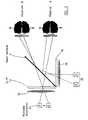
- Figure 1shows a plan view of a comparative example of a direct view 3D display incorporating a beam combiner.
- First and second image dataare presented to first and second spatial light modulators 1a and 1b, respectively, for production of first and second 2D images.
- Each of the first and second spatial light modulators 1a and 1bis illuminated by a respective movable illuminator 2a and 2b providing movable sources of illumination.
- Light from the illuminators 2a and 2bis directed by respective lenses 3a and 3b towards the spatial light modulators 1a and 1b.
- the lightis intensity modulated by the spatial light modulators 1 a and 1b to form two 2D images.
- the 2D imagesare of the same object or objects, but from different directions.
- the imagesare then combined by a beam combiner 4 to create the 3D image.
- the sources of illumination 2a and 2bare arranged to produce light emanating from the positions indicated at "A" with the observer at position 1 as shown in Figure 1. If, however, the observer moves to position 2, then the light emanates from the positions "B" in order to maintain the appearance of a 3D image.
- the relative positions of the sources of illumination 2a and 2b with respect to the lenses 3a and 3b adjacent the SLMs 1a and 1bare controlled in response to movement of the observer.
- the displaymay be controlled so as to maintain the appearance of a 3D image in response to movement by the observer, but maintaining the same point of view.
- the image data presented to the SLMsmay be modified in response to movement of the observer so as to present appropriate new views, for example to simulate movement around an object.
- the display of Figure 1is also suitable for use with a plurality of observers, as shown in Figure 2.
- the illuminators 2a and 2bcomprise a plurality of light sources arranged such that two or more light sources can be in use simultaneously. Both viewers can then view the same 3D image simultaneously and from the same point of view.
- each of the spatial light modulatorsmay be a 250mm diagonal dimension liquid crystal device (LCD).
- the illuminatorsmay be spaced 500mm from the respective LCDs and the optical path length from the LCDs to the observer position may be nominally one metre.
- the illuminatorsmay then consist of illuminator elements 32.5mm wide (so that the window size at the observer is nominally 65mm wide) which perform translatory movement, or which are switched on and off so as to simulate movement in a step wise manner, in response to lateral movement of the observer, at half the speed of the observer.
- the optical systemi.e. the lenses 3, SLMs 1 and the beam combiner 4, make efficient use of the light available from the illuminators 2a and 2b, giving rise to a bright image.
- FIG. 3shows the general principles of a projection display apparatus. Apparatuses of this type are disclosed in an earlier British Patent Application No. 9323402.9.
- image data for two viewsare presented to two SLMs 1a and 1b.
- the SLMsspatially modulate light from respective illuminators to form two 2D images which are then combined by a beam combiner 4.
- the illuminatorsare imaged into the aperture of a projection lens 10.
- the total output numerical aperturedefines the maximum angular extent of the output view directions when the final image screen is a lens.
- first and second lenticular screens 12 and 14 acting as an angular amplifying elementare used as an output element, as shown, then output lobes are generated by the second lenticular screen 14 enhancing the total viewing cone of the display.
- the first lenticular screen 12is arranged to form an image at a diffuser 16.
- the diffuser 16lies in the object plane of the second lenticular screen 14.
- the positions of the illuminatorsare controlled so as to track the movement of the at least one observer.
- 50mm LCD screensare imaged by an 80mm f#1.9 projection lens to a 250mm image size at a 3:1 angular amplifying screen.
- the observer distance from the screenwill be 1000mm with approximately 200mm lateral freedom of movement.
- the illuminator image at the viewer planecan be vertically extended, thereby giving a wide range of possible viewing heights from which the image can be seen.
- the at least one illuminatormay provide vertically extended sources of illumination or a vertical diffuser element may be provided at the output screen plane. Alternatively, the position of the at least one source of illumination may be moved vertically in correspondence with the movement of the observer or observers.
- Tilting of the observer's headcan be accommodated, in displays which do not use arrays of (cylindrical) lenticules, by tilting the or each source of illumination.
- the imagehas to be modified in order to maintain the 3D autostereoscopic effect.
- the size of the illuminated area of the or each illuminatormay be altered if the or each illuminator is moved longitudinally in response to longitudinal movement of the observer, so as to compensate for the change in the angle subtended at the observer's eyes.
- tracking systemsmay be used so as to control the tracking of one or more observers by the display.
- the or each observermay communicate his position by way of an input device such as a joy stick.
- the or each observer's positionmay be sensed by an ultrasonic tracking system or the or each observer may wear a magnet to indicate his position to a magnetic tracking system.
- one or more camerasmay scan the viewing region to determine the or each observer's position, for instance supplying image data to a system which recognises the eyes of the or each observer.
- the or each observerwears a reflector which reflects electromagnetic energy, such as infrared energy.
- a scanning infrared source and an infrared detector or a wide angle infrared source and a scanning infrared detectordetermine the position of the or each reflector which is preferably worn between the eyes of the observer.
- the or each observermay issue voice commands, such as UP,LEFT,HERE etc to direct the display or to allow an audio controlled tracking system to identify the position of the source of the observer's voice.
- Figure 4shows the principles of operation of a display system incorporating an observer tracking system.
- Image datarepresenting multiple views of an object 26 captured by a plurality of cameras 28 or generated by computer 30, are presented via an image controller to a system controller 32.
- the system controller 32is responsive to the position of an observer as determined by an observer tracking detector 34.
- the system controller 32issues instructions to an illuminator position controller 36 to control the illuminators.
- the system controller 32also determines which of the views are reproduced by the spatial light modulators of the autostereoscopic 3D display 38.
- FIG 5shows a further example of a comparative projection display apparatus.
- Image data for two viewsare presented to spatial light modulators 40a and 40b.
- Each of the spatial light modulatorsis illuminated by a respective movable illuminator 42a and 42b.
- Light from the illuminator 42ais directed onto the spatial light modulator 40a via a lens 44a.
- light from the illuminator 42bis directed onto the spatial light modulator 40b via a lens 44b.
- the images formed at the spatial light modulators 40a and 40bare imaged onto an angular amplifying element 46 (for example of the type comprising first and second lenticular screens 12 and 14 and a diffuser, as described hereinabove with reference to Figure 3).
- an angular amplifying element 46for example of the type comprising first and second lenticular screens 12 and 14 and a diffuser, as described hereinabove with reference to Figure 3).
- the imagesare imaged through respective lenses 48a and 48b whose apertures are superimposed at a beam combiner 50.
- Such superimposition of the imagessubstantially eliminates keystone distortion of the two images relative to each other.
- This arrangementenables two spatial light modulators to be imaged in a beam combiner configuration without the need for a projection lens having a large back working distance.
- Figure 6shows an embodiment of the invention.
- Thisis an autostereoscopic 3D display of a type similar to that shown in Figure 1 and comprising SLMs 1a and 1b and a beam combiner 4.
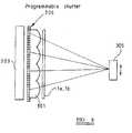
- the illuminators 2a and 2b and the lenses 3a and 3bare replaced by compact light sources 300a and 300b, each of which comprises a lens array 301 such as a lenticular screen behind which is disposed an array of slits forming a shutter 302 and an extended source of illumination 303 ( Figure 7).
- the lenticular screen 301may alternatively be replaced by a parallax barrier.
- Each lenticule of the lenticular screenis aligned with a respective slit so as to control the direction of illumination of the spatial light modulator 1a or 1b so that the left and right images are viewable by the left and right eyes, respectively, of an observer 305 located at a viewing region of the display.
- the shutter 302is connected to a mechanical actuator 304.
- a tracking system for tracking the position of the observer 305supplies control signals to the actuator 304 so as to position the shutter 302 with respect to the lens array 301 so that the observer 305 can see the 3D image.
- the illumination source 303 and the shutter 302thus form a movable source of illumination and the lens array 301 forms an imaging system for imaging the source of illumination at the observer 305.
- Figure 8illustrates an alternative arrangement for tracking an observer in which the mechanically movable shutter 302 and the actuator 304 are replaced by a programmable shutter 306.
- the programmable shutter 306may, for instance, comprise a LCD SLM which is controlled so as to provide transparent slits whose positions are movable in response to movement of the observer 305 so that the 3D image tracks the observer.
- Compact light sources of the type shown in Figures 6 to 8may be used in place of the corresponding components in the other arrangements shown in Figures 3 and 5 the drawings so as to provide relatively compact displays which are capable of tracking one or more than one observer.
Landscapes
- Engineering & Computer Science (AREA)
- Multimedia (AREA)
- Signal Processing (AREA)
- Physics & Mathematics (AREA)
- General Physics & Mathematics (AREA)
- Optics & Photonics (AREA)
- Testing, Inspecting, Measuring Of Stereoscopic Televisions And Televisions (AREA)
Description
- The present invention relates to a display for three dimensional images.
- Known display devices for producing three dimensional (3D) images create the illusionof a 3D opaque object by displaying a number of two dimensional (2D) images to theobserver. Each of the 2D images is a view of the object from a particular direction and,during reproduction of the 3D image, each component 2D image is replayed in itsrespective direction.
- The freedom of movement of the viewer location is limited by the total angular rangeover which the views are imaged. Known displays capable of imaging only a lownumber of 2D views provide a 3D image within a highly restricted range of viewingangles. Consequently the viewer is constrained to be within a limited range of positionsin order to maintain the appearance of a 3D image. Similarly, the number of observersof a 3D image may also be restricted due to the limited number of 2D views.
- "Subjective Assessments of the Resolution of Viewing Directions in a Multi Viewpoint3D TV System", S. Pastoor, K. Schenke, p 217 Proc. SID Vol. 30/3 1989 describes therequirement for the number of views in a 3D display. It is estimated that, for a typicalscene, 60 or more views may be required in an interocular spacing. For a wide field ofview, several hundred views will have to be displayed at some time. It is currently notpossible to achieve this with a simultaneous view presentation type of display.
- A display described by Akiyama.K, and Tetsutani.N in a paper titled "Three dimensionalvisual communication" 1991 ITE Annual convention, p607, has a two view displayproduced by providing an interlaced image on a liquid crystal device (LCD) behind alenticular screen. The position of an observer is monitored and, as the observer movesfrom an orthoscopic viewing zone to a pseudoscopic viewing zone, the sequence inwhich the images are interlaced is reversed so as to maintain the appearance of anorthoscopic image to the observer. Such a system requires precise tracking of the observer's head so as to determine the time at which the image sequence should bereversed. Further, such a display is limited to use by a single observer and the blackmask of the LCD is made visible by the lenticular screen.
- EP-A-0 404 289 "Television set or the like for creating a three dimensional perceptionof images and apparatus for creation of same" describes a 3D display in which alenticular screen is moved with respect to a high resolution display device in response tomovement of an observer. Such an apparatus requires very precise control of the motionof the lenticular screen and is limited for use by a single observer.
GB 2 206 763 discloses a 3D display apparatus of the temporally multiplexed type inwhich 2D images representing views taken from different directions are supplied to anLCD. A spatially modulated light source such as a cathode ray tube (CRT) is disposedin the focal plane of a lens disposed adjacent the LCD. Different regions of the CRTscreen are illuminated in synchronism with the different 2D images displayed by theLCD so that the views are visible in the directions from which they were taken.- US Patent No. 4 649 425 discloses, in Figures 7 and 8, a display device according to thepreamble of
claim 1. Cathode ray tubes are used as the first and second displays. - US Patent No. 2 883 906 discloses a display device.The display device of US Patent No. 2 883 906 does not have an observer trackingsystem.
- According to a first aspect of the invention, there is provided an autostereoscopic displayapparatus as defined in the appended
Claim 1. - Preferred embodiments of the invention are defined in the other appended claims.
- It is thus possible to provide an autostereoscopic display for displaying a 3D imagewhich can track the movement of one or more observers. The or each observer has asubstantially increased degree of freedom of movement within which the 3D image isvisible.
- The present invention will further be described, by way of example, with reference tothe accompanying drawings, in which:
- Figure 1 is a schematic diagram illustrating the general principles of a display apparatususing a beam combiner;
- Figure 2 is a schematic diagram showing the apparatus of Figure 1 in use with twoobservers;
- Figure 3 is a schematic diagram illustrating the general principles of a projection displayapparatus;
- Figure 4 is a schematic diagram of a display apparatus incorporating an observertracking system;
- Figure 5 is a schematic diagram of another comparative display apparatus;
- Figure 6 is a schematic diagram of a display apparatus constituting an embodiment ofthe invention;
- Figure 7 shows part of the display of Figure 6 in more detail; and
- Figure 8 shows a modification of the display of Figure 6.
- Figure 1 shows a plan view of a comparative example of a direct view 3D displayincorporating a beam combiner. First and second image data are presented to first andsecond
spatial light modulators spatial light modulators movable illuminator illuminators respective lenses 3aand 3b towards thespatial light modulators spatial light modulators - The sources of
illumination position 1 as shown in Figure 1. If,however, the observer moves toposition 2, then the light emanates from the positions"B" in order to maintain the appearance of a 3D image. Thus the relative positions ofthe sources ofillumination lenses 3a and 3b adjacent theSLMs - The display of Figure 1 is also suitable for use with a plurality of observers, as shown inFigure 2. The
illuminators - In an example, each of the spatial light modulators may be a 250mm diagonal dimensionliquid crystal device (LCD). The illuminators may be spaced 500mm from therespective LCDs and the optical path length from the LCDs to the observer position maybe nominally one metre. The illuminators may then consist of illuminator elements32.5mm wide (so that the window size at the observer is nominally 65mm wide) whichperform translatory movement, or which are switched on and off so as to simulatemovement in a step wise manner, in response to lateral movement of the observer, athalf the speed of the observer.
- The optical system, i.e. the lenses 3,
SLMs 1 and the beam combiner 4, make efficientuse of the light available from theilluminators - Figure 3 shows the general principles of a projection display apparatus. Apparatuses ofthis type are disclosed in an earlier British Patent Application No. 9323402.9. Asdescribed hereinabove, image data for two views are presented to two
SLMs beam combiner 4. However, instead of being directlyviewed by the observer, the illuminators are imaged into the aperture of aprojection lens 10. The total output numerical aperture defines the maximum angular extent of theoutput view directions when the final image screen is a lens. - However, if a combination of first and second
lenticular screens lenticular screen 14 enhancing the total viewing cone of thedisplay. The firstlenticular screen 12 is arranged to form an image at adiffuser 16. Thediffuser 16 lies in the object plane of the secondlenticular screen 14. As with the otherembodiments described hereinbefore, the positions of the illuminators are controlled soas to track the movement of the at least one observer. In an example display system,50mm LCD screens are imaged by an 80mm f#1.9 projection lens to a 250mm imagesize at a 3:1 angular amplifying screen. The observer distance from the screen will be1000mm with approximately 200mm lateral freedom of movement. - Vertical movement can be accommodated in a number of ways. The illuminator imageat the viewer plane can be vertically extended, thereby giving a wide range of possibleviewing heights from which the image can be seen. The at least one illuminator mayprovide vertically extended sources of illumination or a vertical diffuser element may beprovided at the output screen plane. Alternatively, the position of the at least one sourceof illumination may be moved vertically in correspondence with the movement of theobserver or observers.
- Tilting of the observer's head can be accommodated, in displays which do not use arraysof (cylindrical) lenticules, by tilting the or each source of illumination. However, theimage has to be modified in order to maintain the 3D autostereoscopic effect. Similarly,the size of the illuminated area of the or each illuminator may be altered if the or eachilluminator is moved longitudinally in response to longitudinal movement of theobserver, so as to compensate for the change in the angle subtended at the observer'seyes.
- Various types of tracking systems may be used so as to control the tracking of one ormore observers by the display. For instance, the or each observer may communicate hisposition by way of an input device such as a joy stick. In another embodiment, the oreach observer's position may be sensed by an ultrasonic tracking system or the or eachobserver may wear a magnet to indicate his position to a magnetic tracking system. In afurther embodiment, one or more cameras may scan the viewing region to determine theor each observer's position, for instance supplying image data to a system whichrecognises the eyes of the or each observer. In yet a further embodiment, the or eachobserver wears a reflector which reflects electromagnetic energy, such as infraredenergy. A scanning infrared source and an infrared detector or a wide angle infraredsource and a scanning infrared detector determine the position of the or each reflectorwhich is preferably worn between the eyes of the observer. In a still furtherembodiment, the or each observer may issue voice commands, such as UP,LEFT,HEREetc to direct the display or to allow an audio controlled tracking system to identify theposition of the source of the observer's voice.
- Figure 4 shows the principles of operation of a display system incorporating an observertracking system. Image data, representing multiple views of an
object 26 captured by aplurality ofcameras 28 or generated bycomputer 30, are presented via an imagecontroller to asystem controller 32. Thesystem controller 32 is responsive to theposition of an observer as determined by anobserver tracking detector 34. Thesystemcontroller 32 issues instructions to anilluminator position controller 36 to control theilluminators. Thesystem controller 32 also determines which of the views arereproduced by the spatial light modulators of theautostereoscopic 3D display 38. - Figure 5 shows a further example of a comparative projection display apparatus. Imagedata for two views are presented to spatial
light modulators movable illuminator 42a and 42b.Light from the illuminator 42a is directed onto the spatiallight modulator 40a via a lens44a. Similarly light from theilluminator 42b is directed onto the spatiallight modulator 40b via alens 44b. The images formed at the spatiallight modulators lenticular screens respective lenses beam combiner 50. Such superimposition of theimages substantially eliminates keystone distortion of the two images relative to eachother. This arrangement enables two spatial light modulators to be imaged in a beamcombiner configuration without the need for a projection lens having a large backworking distance. - Figure 6 shows an embodiment of the invention. This is an autostereoscopic 3D displayof a type similar to that shown in Figure 1 and comprising
SLMs beamcombiner 4. However, theilluminators lenses 3a and 3b are replacedbycompact light sources lens array 301 suchas a lenticular screen behind which is disposed an array of slits forming ashutter 302and an extended source of illumination 303 (Figure 7). Thelenticular screen 301 mayalternatively be replaced by a parallax barrier. Each lenticule of the lenticular screen is aligned with a respective slit so as to control the direction of illumination of the spatiallight modulator observer 305 located at a viewing region of the display. - The
shutter 302 is connected to amechanical actuator 304. A tracking system fortracking the position of theobserver 305 supplies control signals to theactuator 304 soas to position theshutter 302 with respect to thelens array 301 so that theobserver 305can see the 3D image. Theillumination source 303 and theshutter 302 thus form amovable source of illumination and thelens array 301 forms an imaging system forimaging the source of illumination at theobserver 305. - Figure 8 illustrates an alternative arrangement for tracking an observer in which themechanically
movable shutter 302 and theactuator 304 are replaced by aprogrammableshutter 306. Theprogrammable shutter 306 may, for instance, comprise a LCD SLMwhich is controlled so as to provide transparent slits whose positions are movable inresponse to movement of theobserver 305 so that the 3D image tracks the observer. - Compact light sources of the type shown in Figures 6 to 8 may be used in place of thecorresponding components in the other arrangements shown in Figures 3 and 5 thedrawings so as to provide relatively compact displays which are capable of tracking oneor more than one observer.
Claims (6)
- An autostereoscopic display for displaying a three dimensional image, comprisingan observer tracking system (34) for tracking the position of an observer, first andsecond displays (1a, 1b, 300a, 300b) for displaying left and right two dimensionalimages, respectively, a beam combiner (4) for combining light from the first and seconddisplays (1a, 1b, 300a, 300b), first and second shutters (302) and first and secondimaging systems (301) for imaging light at a first viewing region, the first and secondshutters (302) being movable with respect to the first and second imaging systems (301),respectively, so that the first viewing region tracks the position of the observerdetermined by the observer tracking system;
characterised in that the first and second displays (1a, 1b, 300a, 300b) comprisefirst and second extended sources of illumination (303) and first and second spatial lightmodulators (1a, 1b) for modulating light from the first and second extended sources ofillumination (303) with the left and right two dimensional images, respectively, the firstand second extended sources of illumination (303) being arranged in sequence with thefirst and second shutters (302) and the first and second imaging systems (301), the firstand second imaging systems (301) being lens arrays or parallax barriers for imaginglight from the first and second sources of illumination (303) via the first and secondshutters (302), respectively, at the first viewing region, the first and second imagingsystems (301) being fixed and the first and second shutters (302) being movable so thatthe first viewing region tracks the position of the observer determined by the observertracking system. - A display as claimed in claim 1,characterised in that each of the first and secondimaging systems (301) comprises a lens array.
- A display as claimed in claim 2,characterised in that each of the lens arrays (301)comprises a lenticular screen.
- A display as claimed in claim 1,characterised in that each of the first and secondimaging systems (301) comprises a parallax barrier.
- A display as claimed in any one of the preceding claims,characterised in that eachof the first and second shutters (302) comprises an array of slits.
- A display as claimed in any one of the preceding claims,characterised by amechanical actuator (304) responsive to the observer tracking system (34) for movingthe first and second shutters (302) with respect to the first and second imaging systems(301), respectively.
Applications Claiming Priority (5)
| Application Number | Priority Date | Filing Date | Title |
|---|---|---|---|
| GB9324703AGB2284487A (en) | 1993-12-01 | 1993-12-01 | Display for 3D images |
| GB9324703 | 1993-12-01 | ||
| GB9421278AGB2294350A (en) | 1994-10-21 | 1994-10-21 | Light source and display |
| GB9421278 | 1994-10-21 | ||
| EP94308874AEP0656555B1 (en) | 1993-12-01 | 1994-11-30 | Display for 3D images |
Related Parent Applications (1)
| Application Number | Title | Priority Date | Filing Date |
|---|---|---|---|
| EP94308874ADivisionEP0656555B1 (en) | 1993-12-01 | 1994-11-30 | Display for 3D images |
Publications (3)
| Publication Number | Publication Date |
|---|---|
| EP1209508A2 EP1209508A2 (en) | 2002-05-29 |
| EP1209508A3 EP1209508A3 (en) | 2003-03-19 |
| EP1209508B1true EP1209508B1 (en) | 2004-10-27 |
Family
ID=26303951
Family Applications (2)
| Application Number | Title | Priority Date | Filing Date |
|---|---|---|---|
| EP94308874AExpired - LifetimeEP0656555B1 (en) | 1993-12-01 | 1994-11-30 | Display for 3D images |
| EP20020100151Expired - LifetimeEP1209508B1 (en) | 1993-12-01 | 1994-11-30 | Display for 3D images |
Family Applications Before (1)
| Application Number | Title | Priority Date | Filing Date |
|---|---|---|---|
| EP94308874AExpired - LifetimeEP0656555B1 (en) | 1993-12-01 | 1994-11-30 | Display for 3D images |
Country Status (4)
| Country | Link |
|---|---|
| US (1) | US6014164A (en) |
| EP (2) | EP0656555B1 (en) |
| JP (1) | JP3199345B2 (en) |
| DE (2) | DE69432283T2 (en) |
Cited By (1)
| Publication number | Priority date | Publication date | Assignee | Title |
|---|---|---|---|---|
| CN102262298A (en)* | 2011-06-07 | 2011-11-30 | 北京理工大学 | Large-field scanning infrared optical system comprising transmission-type spatial light modulator |
Families Citing this family (195)
| Publication number | Priority date | Publication date | Assignee | Title |
|---|---|---|---|---|
| GB2296400A (en)* | 1994-12-16 | 1996-06-26 | Sharp Kk | Autostereoscopic display having a high resolution 2D mode |
| GB2296617A (en)* | 1994-12-29 | 1996-07-03 | Sharp Kk | Observer tracking autosteroscopic display |
| GB2297389A (en) | 1995-01-28 | 1996-07-31 | Sharp Kk | Three dimensional display having autostereoscopic and stereoscopic modes |
| GB2297876A (en)* | 1995-02-09 | 1996-08-14 | Sharp Kk | Observer tracking autostereoscopic display |
| JPH0954376A (en)* | 1995-06-09 | 1997-02-25 | Pioneer Electron Corp | Stereoscopic display device |
| US6377230B1 (en)* | 1995-10-05 | 2002-04-23 | Semiconductor Energy Laboratory Co., Ltd. | Three dimensional display unit and display method |
| GB2306826A (en) | 1995-10-18 | 1997-05-07 | Sharp Kk | Display, method of calibrating an observer tracking display and observer tracking autostereoscopic 3D display |
| GB2320156A (en)* | 1996-12-07 | 1998-06-10 | Sharp Kk | Directional display and method of making a mask for a directional display |
| GB2317771A (en)* | 1996-09-27 | 1998-04-01 | Sharp Kk | Observer tracking directional display |
| DE19641480A1 (en)* | 1996-10-09 | 1998-04-30 | Tan Helmut | Method for stereoscopic projection of 3D image representations on an image display device |
| EP1008887A1 (en)* | 1997-01-22 | 2000-06-14 | DOMINGUEZ MONTES, Juan | Display screen for three-dimensional images |
| JP3441911B2 (en) | 1997-02-20 | 2003-09-02 | キヤノン株式会社 | Information processing apparatus and method |
| WO1998043441A1 (en) | 1997-03-27 | 1998-10-01 | Litton Systems, Inc. | Autostereoscopic projection system |
| US5993003A (en)* | 1997-03-27 | 1999-11-30 | Litton Systems, Inc. | Autostereo projection system |
| GB2324428A (en)* | 1997-04-17 | 1998-10-21 | Sharp Kk | Image tracking; observer tracking stereoscopic display |
| WO1998057215A1 (en)* | 1997-06-09 | 1998-12-17 | Dominguez Montes Juan | Optical adaptor couplable to any diffusing screen pertaining to a single conventional reproduction device, capable of producing tridimensional effects |
| ES2152905B1 (en)* | 1997-06-09 | 2001-08-16 | Dominguez Montes Juan | OPTICAL ADAPTER COUPLABLE TO ANY DISPLAY SCREEN BELONGING TO A SINGLE CONVENTIONAL REPRODUCTION DEVICE, ABLE TO PRODUCE THREE-DIMENSIONAL EFFECTS. |
| JPH11234703A (en)* | 1998-02-09 | 1999-08-27 | Toshiba Corp | 3D display device |
| GB2337388A (en)* | 1998-05-12 | 1999-11-17 | Sharp Kk | Directional autereoscopic 3D display having directional illumination system |
| US6525699B1 (en) | 1998-05-21 | 2003-02-25 | Nippon Telegraph And Telephone Corporation | Three-dimensional representation method and an apparatus thereof |
| US6831624B1 (en) | 1999-01-15 | 2004-12-14 | Sharp Kabushiki Kaisha | Time sequentially scanned display |
| US6469830B1 (en) | 1999-04-01 | 2002-10-22 | Honeywell Inc. | Display screen and method of manufacture therefor |
| US6278546B1 (en) | 1999-04-01 | 2001-08-21 | Honeywell International Inc. | Display screen and method of manufacture therefor |
| US6597398B1 (en)* | 1999-06-02 | 2003-07-22 | Intel Corporation | Image sensor response enhancement using fluorescent phosphors |
| US7061678B1 (en)* | 1999-11-10 | 2006-06-13 | Thomson Licensing | Stereoscopic display device with two back light sources |
| KR100710347B1 (en)* | 2000-05-12 | 2007-04-23 | 엘지전자 주식회사 | 3D image display device and method |
| JP3738691B2 (en)* | 2001-01-05 | 2006-01-25 | セイコーエプソン株式会社 | Light modulation device position adjustment device, light modulation device position adjustment method, and initial position adjustment jig |
| EP1378783B1 (en)* | 2001-03-19 | 2005-05-25 | Juan Dominguez-Montes | System for reproducing three-dimensional images |
| US6752498B2 (en) | 2001-05-14 | 2004-06-22 | Eastman Kodak Company | Adaptive autostereoscopic display system |
| TW476002B (en)* | 2001-05-31 | 2002-02-11 | Ind Tech Res Inst | Vertical parallax barrier bare eye three-dimensional display device |
| DE60238691D1 (en) | 2001-08-21 | 2011-02-03 | Koninkl Philips Electronics Nv | AUTOSTEREOSCOPIC IMAGE DISPLAY DEVICE WITH USER SUCCESSION SYSTEM |
| GB2379347A (en)* | 2001-08-30 | 2003-03-05 | Holographic Imaging Llc | Replay optics for holographic displays |
| JP2005513885A (en)* | 2001-12-14 | 2005-05-12 | コーニンクレッカ フィリップス エレクトロニクス エヌ ヴィ | Stereoscopic display device and system |
| GB2387664B (en)* | 2002-04-17 | 2005-08-24 | Philip Anthony Surman | Autostereoscopic display |
| US6768585B2 (en)* | 2002-05-02 | 2004-07-27 | Eastman Kodak Company | Monocentric autostereoscopic optical apparatus using a scanned linear electromechanical modulator |
| WO2004053563A1 (en)* | 2002-12-11 | 2004-06-24 | Oleg Leonidovich Golovkov | Device for displaying a stereoscopic image |
| JP4003129B2 (en)* | 2003-01-22 | 2007-11-07 | ソニー株式会社 | Stereoscopic imaging device, stereoscopic display device, stereoscopic imaging display device, and information recording method |
| JP2004226835A (en)* | 2003-01-24 | 2004-08-12 | Pioneer Electronic Corp | Display device and display method |
| JP2004258163A (en)* | 2003-02-25 | 2004-09-16 | Nec Corp | Stereoscopic image display device and stereoscopic image display method |
| JP3935095B2 (en) | 2003-03-20 | 2007-06-20 | 株式会社ソフィア | Image display device and light source unit |
| JP3953434B2 (en) | 2003-03-20 | 2007-08-08 | 株式会社ソフィア | Image display device |
| KR101547077B1 (en) | 2003-04-09 | 2015-08-25 | 가부시키가이샤 니콘 | Exposure method and apparatus, and device manufacturing method |
| DE10339076B4 (en) | 2003-08-26 | 2007-10-31 | Seereal Technologies Gmbh | Autostereoscopic multi-user display |
| US6886940B2 (en)* | 2003-08-28 | 2005-05-03 | Eastman Kodak Company | Autostereoscopic display for multiple viewers |
| GB2405519A (en)* | 2003-08-30 | 2005-03-02 | Sharp Kk | A multiple-view directional display |
| DE10340089B4 (en)* | 2003-08-30 | 2005-12-22 | Seereal Technologies Gmbh | Sweet-spot beam splitter for image separation |
| US6834961B1 (en)* | 2003-09-12 | 2004-12-28 | Eastman Kodak Company | Autostereoscopic optical apparatus |
| US6871956B1 (en)* | 2003-09-12 | 2005-03-29 | Eastman Kodak Company | Autostereoscopic optical apparatus |
| DE10344323A1 (en)* | 2003-09-22 | 2005-04-21 | X3D Technologies Gmbh | Method and arrangement for spatial representation |
| TWI573175B (en) | 2003-10-28 | 2017-03-01 | 尼康股份有限公司 | Optical illumination device, exposure device, exposure method and device manufacturing method |
| TWI275872B (en)* | 2003-11-07 | 2007-03-11 | Hon Hai Prec Ind Co Ltd | Liquid crystal display |
| TWI385414B (en) | 2003-11-20 | 2013-02-11 | 尼康股份有限公司 | Optical illuminating apparatus, illuminating method, exposure apparatus, exposure method and device fabricating method |
| KR100580632B1 (en)* | 2003-12-05 | 2006-05-16 | 삼성전자주식회사 | Display that can selectively display 2D and 3D images |
| DE10359403B4 (en)* | 2003-12-18 | 2005-12-15 | Seereal Technologies Gmbh | Autostereoscopic multi-user display |
| TWI389174B (en) | 2004-02-06 | 2013-03-11 | 尼康股份有限公司 | Polarization changing device, optical illumination apparatus, light-exposure apparatus and light-exposure method |
| US20050206883A1 (en)* | 2004-03-22 | 2005-09-22 | Gao Wen L | Single source, single camera inspection system |
| GB0410551D0 (en)* | 2004-05-12 | 2004-06-16 | Ller Christian M | 3d autostereoscopic display |
| GB0412651D0 (en)* | 2004-06-07 | 2004-07-07 | Microsharp Corp Ltd | Autostereoscopic rear projection screen and associated display system |
| FR2873458B1 (en)* | 2004-07-22 | 2006-11-03 | Dalila Morales | METHOD AND DEVICE FOR VISION IN RELIEF ON SCREEN |
| WO2006015562A1 (en)* | 2004-08-10 | 2006-02-16 | Seereal Technologies Gmbh | Sweet-spot image separation device for autostereoscopic multi-user displays |
| US9030532B2 (en)* | 2004-08-19 | 2015-05-12 | Microsoft Technology Licensing, Llc | Stereoscopic image display |
| US20060050384A1 (en)* | 2004-09-08 | 2006-03-09 | Eastman Kodak Company | System for displaying images in auto-stereoscopic format |
| JP2006134975A (en)* | 2004-11-04 | 2006-05-25 | Hitachi Displays Ltd | LIGHTING DEVICE AND DISPLAY DEVICE USING THE LIGHTING DEVICE |
| DE102005004303B4 (en) | 2005-01-24 | 2007-09-06 | Seereal Technologies Gmbh | Image display device with an imaging matrix |
| KR20180128526A (en) | 2005-05-12 | 2018-12-03 | 가부시키가이샤 니콘 | Projection optical system, exposure apparatus and device manufacturing method |
| KR100730404B1 (en) | 2005-06-30 | 2007-06-19 | 광운대학교 산학협력단 | Stereoscopic video display |
| KR100782831B1 (en) | 2006-01-03 | 2007-12-06 | 삼성전자주식회사 | Field sequential autostereoscopic display arrangement with high resolution |
| CN100501566C (en)* | 2006-01-05 | 2009-06-17 | 李明 | Curved surface movie projection system and method |
| DE102006004300A1 (en)* | 2006-01-20 | 2007-08-02 | Seereal Technologies S.A. | Projection device for holographic reconstruction of scenes, comprises reproduction medium, which is used to reproduce Fourier transformation of light from light source modulated by light modulation device onto screen |
| CA2649415C (en)* | 2006-04-19 | 2018-01-16 | Setred As | High speed display shutter for autostereoscopic display |
| US20070252953A1 (en)* | 2006-04-27 | 2007-11-01 | Robert Metzger | Crosstalk reduced stereoscopic viewing apparatus |
| IL176673A0 (en)* | 2006-07-03 | 2007-07-04 | Fermon Israel | A variably displayable mobile device keyboard |
| GB0716776D0 (en)* | 2007-08-29 | 2007-10-10 | Setred As | Rendering improvement for 3D display |
| US8451427B2 (en) | 2007-09-14 | 2013-05-28 | Nikon Corporation | Illumination optical system, exposure apparatus, optical element and manufacturing method thereof, and device manufacturing method |
| JP5267029B2 (en) | 2007-10-12 | 2013-08-21 | 株式会社ニコン | Illumination optical apparatus, exposure apparatus, and device manufacturing method |
| CN101681125B (en) | 2007-10-16 | 2013-08-21 | 株式会社尼康 | Illumination optical system, exposure apparatus, and device manufacturing method |
| CN101681123B (en) | 2007-10-16 | 2013-06-12 | 株式会社尼康 | Illumination optical system, exposure apparatus, and device manufacturing method |
| US8379187B2 (en) | 2007-10-24 | 2013-02-19 | Nikon Corporation | Optical unit, illumination optical apparatus, exposure apparatus, and device manufacturing method |
| US9116346B2 (en) | 2007-11-06 | 2015-08-25 | Nikon Corporation | Illumination apparatus, illumination method, exposure apparatus, and device manufacturing method |
| JP4803837B2 (en)* | 2008-01-08 | 2011-10-26 | 株式会社ナナオ | Stereoscopic image display device |
| WO2009091365A1 (en)* | 2008-01-17 | 2009-07-23 | Thomson Licensing | Display system |
| CN105606344B (en) | 2008-05-28 | 2019-07-30 | 株式会社尼康 | Lamp optical system, means of illumination, exposure device and exposure method |
| US20100033813A1 (en)* | 2008-08-05 | 2010-02-11 | Rogoff Gerald L | 3-D Display Requiring No Special Eyewear |
| US8199186B2 (en)* | 2009-03-05 | 2012-06-12 | Microsoft Corporation | Three-dimensional (3D) imaging based on motionparallax |
| JP2012520508A (en)* | 2009-03-10 | 2012-09-06 | スリーエム イノベイティブ プロパティズ カンパニー | User interface with floating composite image |
| US7978407B1 (en) | 2009-06-27 | 2011-07-12 | Holovisions LLC | Holovision (TM) 3D imaging with rotating light-emitting members |
| US8354806B2 (en)* | 2009-08-21 | 2013-01-15 | Microsoft Corporation | Scanning collimation of light via flat panel lamp |
| WO2011044936A1 (en) | 2009-10-14 | 2011-04-21 | Nokia Corporation | Autostereoscopic rendering and display apparatus |
| ES2412729T3 (en) | 2009-10-28 | 2013-07-12 | Juan Dominguez-Montes | Stereoscopic Reproduction System |
| US8587498B2 (en)* | 2010-03-01 | 2013-11-19 | Holovisions LLC | 3D image display with binocular disparity and motion parallax |
| TWI417630B (en)* | 2010-05-18 | 2013-12-01 | Delta Electronics Inc | Display apparatus for displaying multiple view angle images |
| KR102116284B1 (en)* | 2010-05-21 | 2020-06-01 | 코닌클리케 필립스 엔.브이. | Multi-view display device |
| US9030536B2 (en) | 2010-06-04 | 2015-05-12 | At&T Intellectual Property I, Lp | Apparatus and method for presenting media content |
| EP2395759B1 (en)* | 2010-06-11 | 2015-03-04 | Sony Ericsson Mobile Communications AB | Autostereoscopic display device and method for operating an autostereoscopic display device |
| US8402502B2 (en) | 2010-06-16 | 2013-03-19 | At&T Intellectual Property I, L.P. | Method and apparatus for presenting media content |
| US9787974B2 (en) | 2010-06-30 | 2017-10-10 | At&T Intellectual Property I, L.P. | Method and apparatus for delivering media content |
| US8640182B2 (en) | 2010-06-30 | 2014-01-28 | At&T Intellectual Property I, L.P. | Method for detecting a viewing apparatus |
| US8593574B2 (en) | 2010-06-30 | 2013-11-26 | At&T Intellectual Property I, L.P. | Apparatus and method for providing dimensional media content based on detected display capability |
| US8918831B2 (en) | 2010-07-06 | 2014-12-23 | At&T Intellectual Property I, Lp | Method and apparatus for managing a presentation of media content |
| US9049426B2 (en) | 2010-07-07 | 2015-06-02 | At&T Intellectual Property I, Lp | Apparatus and method for distributing three dimensional media content |
| US9232274B2 (en) | 2010-07-20 | 2016-01-05 | At&T Intellectual Property I, L.P. | Apparatus for adapting a presentation of media content to a requesting device |
| US9560406B2 (en) | 2010-07-20 | 2017-01-31 | At&T Intellectual Property I, L.P. | Method and apparatus for adapting a presentation of media content |
| US9032470B2 (en) | 2010-07-20 | 2015-05-12 | At&T Intellectual Property I, Lp | Apparatus for adapting a presentation of media content according to a position of a viewing apparatus |
| US8994716B2 (en) | 2010-08-02 | 2015-03-31 | At&T Intellectual Property I, Lp | Apparatus and method for providing media content |
| US8438502B2 (en) | 2010-08-25 | 2013-05-07 | At&T Intellectual Property I, L.P. | Apparatus for controlling three-dimensional images |
| KR101652401B1 (en)* | 2010-09-07 | 2016-08-31 | 삼성전자주식회사 | 3D image display apparatus and 3D image display method |
| US8947511B2 (en) | 2010-10-01 | 2015-02-03 | At&T Intellectual Property I, L.P. | Apparatus and method for presenting three-dimensional media content |
| US20140041205A1 (en) | 2010-11-19 | 2014-02-13 | Reald Inc. | Method of manufacturing directional backlight apparatus and directional structured optical film |
| US9250448B2 (en) | 2010-11-19 | 2016-02-02 | Reald Inc. | Segmented directional backlight and related methods of backlight illumination |
| US8651726B2 (en) | 2010-11-19 | 2014-02-18 | Reald Inc. | Efficient polarized directional backlight |
| WO2012068532A2 (en) | 2010-11-19 | 2012-05-24 | Reald Inc. | Directional flat illuminators |
| AU2011356545B2 (en) | 2011-01-18 | 2013-12-19 | Hisense Electric Co., Ltd | Control method and apparatus for stereoscopic display |
| US9201185B2 (en) | 2011-02-04 | 2015-12-01 | Microsoft Technology Licensing, Llc | Directional backlighting for display panels |
| KR20120107312A (en) | 2011-03-21 | 2012-10-02 | 한국과학기술연구원 | 3-dimensional displaying apparatus and driving method thereof |
| EP2508931A1 (en)* | 2011-04-05 | 2012-10-10 | Advanced Acoustic SF GmbH | Micro mirror array screen |
| CN102736393B (en)* | 2011-04-07 | 2014-12-17 | 台达电子工业股份有限公司 | Display device for displaying multiple visual angle images |
| CN102322959B (en)* | 2011-06-07 | 2014-02-19 | 北京理工大学 | Large field of view scanning infrared optical system with aspheric dome |
| US9024927B2 (en) | 2011-06-15 | 2015-05-05 | Semiconductor Energy Laboratory Co., Ltd. | Display device and method for driving the same |
| US9602766B2 (en) | 2011-06-24 | 2017-03-21 | At&T Intellectual Property I, L.P. | Apparatus and method for presenting three dimensional objects with telepresence |
| US9445046B2 (en) | 2011-06-24 | 2016-09-13 | At&T Intellectual Property I, L.P. | Apparatus and method for presenting media content with telepresence |
| US9030522B2 (en) | 2011-06-24 | 2015-05-12 | At&T Intellectual Property I, Lp | Apparatus and method for providing media content |
| US8947497B2 (en) | 2011-06-24 | 2015-02-03 | At&T Intellectual Property I, Lp | Apparatus and method for managing telepresence sessions |
| US8878780B2 (en) | 2011-07-10 | 2014-11-04 | Industrial Technology Research Institute | Display apparatus |
| US8587635B2 (en) | 2011-07-15 | 2013-11-19 | At&T Intellectual Property I, L.P. | Apparatus and method for providing media services with telepresence |
| KR20130010834A (en)* | 2011-07-19 | 2013-01-29 | 가부시키가이샤 한도오따이 에네루기 켄큐쇼 | Display device |
| TWI456447B (en) | 2011-08-04 | 2014-10-11 | Au Optronics Corp | Autostereoscopic display device having touch sensing mechanism and driving method thereof |
| US9237337B2 (en) | 2011-08-24 | 2016-01-12 | Reald Inc. | Autostereoscopic display with a passive cycloidal diffractive waveplate |
| WO2013029040A1 (en) | 2011-08-25 | 2013-02-28 | Euro-Pro Operating Llc | Steam cleaning appliance with vibration and heating components |
| JP5100875B1 (en)* | 2011-08-31 | 2012-12-19 | 株式会社東芝 | Viewing area adjustment apparatus, image processing apparatus and viewing area adjustment method |
| FR2980661A1 (en)* | 2011-09-27 | 2013-03-29 | Roger Abraham Sultan | Three-dimensional vision system for e.g. display device, has oculometer locating relative position of eyes compared to image screen to generate control signals in synchronism with alternating display of images from external image source |
| US9354748B2 (en) | 2012-02-13 | 2016-05-31 | Microsoft Technology Licensing, Llc | Optical stylus interaction |
| US9075566B2 (en) | 2012-03-02 | 2015-07-07 | Microsoft Technoogy Licensing, LLC | Flexible hinge spine |
| US9870066B2 (en) | 2012-03-02 | 2018-01-16 | Microsoft Technology Licensing, Llc | Method of manufacturing an input device |
| US9460029B2 (en) | 2012-03-02 | 2016-10-04 | Microsoft Technology Licensing, Llc | Pressure sensitive keys |
| EP2842332A1 (en)* | 2012-04-24 | 2015-03-04 | Koninklijke Philips N.V. | Auto-stereoscopic display device and drive method |
| KR102099590B1 (en) | 2012-05-18 | 2020-04-10 | 리얼디 스파크, 엘엘씨 | Controlling light sources of a directional backlight |
| EP2850473B1 (en) | 2012-05-18 | 2018-09-12 | RealD Spark, LLC | Directional display apparatus |
| EP2850488A4 (en) | 2012-05-18 | 2016-03-02 | Reald Inc | Directional backlight |
| KR102062019B1 (en)* | 2012-05-18 | 2020-01-03 | 리얼디 스파크, 엘엘씨 | Directionally illuminated waveguide arrangement |
| US9188731B2 (en) | 2012-05-18 | 2015-11-17 | Reald Inc. | Directional backlight |
| US9678267B2 (en) | 2012-05-18 | 2017-06-13 | Reald Spark, Llc | Wide angle imaging directional backlights |
| US9235057B2 (en)* | 2012-05-18 | 2016-01-12 | Reald Inc. | Polarization recovery in a directional display device |
| US9350980B2 (en) | 2012-05-18 | 2016-05-24 | Reald Inc. | Crosstalk suppression in a directional backlight |
| KR101541059B1 (en)* | 2012-05-31 | 2015-07-31 | 한국과학기술연구원 | 3-dimensional display apparatus using time division scheme |
| US8947353B2 (en) | 2012-06-12 | 2015-02-03 | Microsoft Corporation | Photosensor array gesture detection |
| US9256089B2 (en) | 2012-06-15 | 2016-02-09 | Microsoft Technology Licensing, Llc | Object-detecting backlight unit |
| WO2014018269A1 (en) | 2012-07-23 | 2014-01-30 | Reald Inc. | Observer tracking autostereoscopic display |
| KR102008213B1 (en)* | 2012-07-27 | 2019-08-08 | 삼성디스플레이 주식회사 | Method of displaying three dimensional image and three dimensional image display apparatus for performing the method |
| US8964379B2 (en) | 2012-08-20 | 2015-02-24 | Microsoft Corporation | Switchable magnetic lock |
| US9420266B2 (en) | 2012-10-02 | 2016-08-16 | Reald Inc. | Stepped waveguide autostereoscopic display apparatus with a reflective directional element |
| WO2014100753A1 (en) | 2012-12-21 | 2014-06-26 | Reald Inc. | Superlens component for directional display |
| KR101371772B1 (en)* | 2013-01-28 | 2014-03-10 | 가톨릭대학교 산학협력단 | Stereovision optometry apparatus |
| CN111487707A (en) | 2013-02-22 | 2020-08-04 | 瑞尔D斯帕克有限责任公司 | directional backlight |
| KR102254799B1 (en) | 2013-06-17 | 2021-05-24 | 리얼디 스파크, 엘엘씨 | Controlling light sources of a directional backlight |
| EP3058562A4 (en) | 2013-10-14 | 2017-07-26 | RealD Spark, LLC | Control of directional display |
| KR102366346B1 (en) | 2013-10-14 | 2022-02-23 | 리얼디 스파크, 엘엘씨 | Light input for directional backlight |
| US9967546B2 (en) | 2013-10-29 | 2018-05-08 | Vefxi Corporation | Method and apparatus for converting 2D-images and videos to 3D for consumer, commercial and professional applications |
| US20150116458A1 (en) | 2013-10-30 | 2015-04-30 | Barkatech Consulting, LLC | Method and apparatus for generating enhanced 3d-effects for real-time and offline appplications |
| CN106062466B (en) | 2013-11-15 | 2020-01-31 | 瑞尔D斯帕克有限责任公司 | Directional backlight with light emitting element package |
| CN103605211B (en)* | 2013-11-27 | 2016-04-20 | 南京大学 | Tablet non-auxiliary stereo display device and method |
| DE102014003351B4 (en) | 2014-03-07 | 2022-11-03 | Dioptic Gmbh | Head-up display and display method |
| US10158847B2 (en) | 2014-06-19 | 2018-12-18 | Vefxi Corporation | Real—time stereo 3D and autostereoscopic 3D video and image editing |
| EP3161550A4 (en) | 2014-06-26 | 2018-04-18 | RealD Spark, LLC | Directional privacy display |
| CN104216130A (en)* | 2014-09-16 | 2014-12-17 | 中山大学 | Naked eye 3D display method, device and system with adjustable depth of visual area |
| WO2016057690A1 (en) | 2014-10-08 | 2016-04-14 | Reald Inc. | Directional backlight |
| US10356383B2 (en) | 2014-12-24 | 2019-07-16 | Reald Spark, Llc | Adjustment of perceived roundness in stereoscopic image of a head |
| ES2660309T3 (en) | 2015-02-10 | 2018-03-21 | Juan Dominguez-Montes | Stereoscopic transparency reproduction system |
| RU2596062C1 (en) | 2015-03-20 | 2016-08-27 | Автономная Некоммерческая Образовательная Организация Высшего Профессионального Образования "Сколковский Институт Науки И Технологий" | Method for correction of eye image using machine learning and method of machine learning |
| WO2016168345A1 (en) | 2015-04-13 | 2016-10-20 | Reald Inc. | Wide angle imaging directional backlights |
| CN107850804B (en) | 2015-05-27 | 2021-06-11 | 瑞尔D斯帕克有限责任公司 | Wide-angle imaging directional backlight |
| US10475418B2 (en) | 2015-10-26 | 2019-11-12 | Reald Spark, Llc | Intelligent privacy system, apparatus, and method thereof |
| WO2017083526A1 (en) | 2015-11-10 | 2017-05-18 | Reald Inc. | Distortion matching polarization conversion systems and methods thereof |
| WO2017083583A1 (en) | 2015-11-13 | 2017-05-18 | Reald Spark, Llc | Surface features for imaging directional backlights |
| EP3374692B1 (en) | 2015-11-13 | 2021-02-24 | RealD Spark, LLC | Wide angle imaging directional backlights |
| CN114143495B (en) | 2016-01-05 | 2025-07-15 | 瑞尔D斯帕克有限责任公司 | Gaze Correction for Multi-View Images |
| EP3458897B1 (en) | 2016-05-19 | 2025-04-02 | RealD Spark, LLC | Wide angle imaging directional backlights |
| US10425635B2 (en) | 2016-05-23 | 2019-09-24 | Reald Spark, Llc | Wide angle imaging directional backlights |
| WO2018129059A1 (en) | 2017-01-04 | 2018-07-12 | Reald Spark, Llc | Optical stack for imaging directional backlights |
| EP3607387A4 (en) | 2017-04-03 | 2020-11-25 | RealD Spark, LLC | Segmented imaging directional backlights |
| US10303030B2 (en) | 2017-05-08 | 2019-05-28 | Reald Spark, Llc | Reflective optical stack for privacy display |
| US10126575B1 (en) | 2017-05-08 | 2018-11-13 | Reald Spark, Llc | Optical stack for privacy display |
| CN116841075A (en) | 2017-05-08 | 2023-10-03 | 瑞尔D斯帕克有限责任公司 | Optical stack for directional display |
| KR102411563B1 (en)* | 2017-05-14 | 2022-06-21 | 레이아 인코포레이티드 | Multiview backlight, display and method using active emitter arrays |
| CN111183405A (en) | 2017-08-08 | 2020-05-19 | 瑞尔D斯帕克有限责任公司 | Adjust the digital representation of the head area |
| TWI878209B (en) | 2017-09-15 | 2025-04-01 | 美商瑞爾D斯帕克有限責任公司 | Display device and a view angle control optical element for application to a display device |
| WO2019090246A1 (en) | 2017-11-06 | 2019-05-09 | Reald Spark, Llc | Privacy display apparatus |
| KR102759510B1 (en) | 2018-01-25 | 2025-02-04 | 리얼디 스파크, 엘엘씨 | Touchscreen for privacy display |
| US10976578B2 (en) | 2018-01-25 | 2021-04-13 | Reald Spark, Llc | Reflective optical stack for privacy display |
| EP3844949B1 (en)* | 2018-08-29 | 2025-05-07 | InterDigital Madison Patent Holdings, SAS | Device and method for displaying voxels |
| CN111381371B (en)* | 2018-12-27 | 2022-04-15 | 中强光电股份有限公司 | Head-mounted display device |
| KR102825825B1 (en)* | 2020-09-14 | 2025-06-26 | 삼성디스플레이 주식회사 | Display device |
| CN116194812A (en) | 2020-09-16 | 2023-05-30 | 瑞尔D斯帕克有限责任公司 | Vehicle Exterior Lighting |
| CN117518701A (en)* | 2022-07-27 | 2024-02-06 | 华为技术有限公司 | Stereoscopic projection system, projection system and vehicle |
| US11966049B2 (en) | 2022-08-02 | 2024-04-23 | Reald Spark, Llc | Pupil tracking near-eye display |
| WO2024035796A1 (en) | 2022-08-11 | 2024-02-15 | Reald Spark, Llc | Anamorphic directional illumination device |
Family Cites Families (19)
| Publication number | Priority date | Publication date | Assignee | Title |
|---|---|---|---|---|
| US2883906A (en)* | 1952-02-04 | 1959-04-28 | Rehorn Miles Parker | Stereoscopic system and apparatus |
| US4649425A (en)* | 1983-07-25 | 1987-03-10 | Pund Marvin L | Stereoscopic display |
| NL8500141A (en)* | 1985-01-21 | 1986-08-18 | Delft Tech Hogeschool | METHOD FOR GENERATING A THREE-DIMENSIONAL IMPRESSION FROM A TWO-DIMENSIONAL IMAGE AT AN OBSERVER |
| US4829365A (en)* | 1986-03-07 | 1989-05-09 | Dimension Technologies, Inc. | Autostereoscopic display with illuminating lines, light valve and mask |
| GB8623490D0 (en)* | 1986-09-30 | 1986-11-05 | Bass M L | Display means for stereoscopic images |
| GB8716369D0 (en)* | 1987-07-10 | 1987-08-19 | Travis A R L | Three-dimensional display device |
| US4987487A (en)* | 1988-08-12 | 1991-01-22 | Nippon Telegraph And Telephone Corporation | Method of stereoscopic images display which compensates electronically for viewer head movement |
| DE3921061A1 (en)* | 1989-06-23 | 1991-01-03 | Hertz Inst Heinrich | DISPLAY DEVICE FOR THREE-DIMENSIONAL PERCEPTION OF IMAGES |
| US5258833A (en)* | 1991-04-08 | 1993-11-02 | Schenk Alan G | Sterescopic television/video system |
| JP2704068B2 (en)* | 1991-10-04 | 1998-01-26 | 富士写真フイルム株式会社 | Stereoscopic image projection method and stereographic printing device |
| GB9206048D0 (en)* | 1992-03-20 | 1992-05-06 | Delta System Design Ltd | Twin screen raster lenticular hybrid |
| GB2267579A (en)* | 1992-05-15 | 1993-12-08 | Sharp Kk | Optical device comprising facing lenticular or parallax screens of different pitch |
| US5311220A (en)* | 1992-06-10 | 1994-05-10 | Dimension Technologies, Inc. | Autostereoscopic display |
| US5327286A (en)* | 1992-08-31 | 1994-07-05 | Texas Instruments Incorporated | Real time optical correlation system |
| US5349379A (en)* | 1992-09-09 | 1994-09-20 | Dimension Technologies Inc. | Autostereoscopic display illumination system allowing viewing zones to follow the observer's head |
| GB2272555A (en)* | 1992-11-11 | 1994-05-18 | Sharp Kk | Stereoscopic display using a light modulator |
| EP0687366B1 (en)* | 1993-03-03 | 2000-01-26 | STREET, Graham Stewart Brandon | Method and apparatus for image alignment |
| DE4309667A1 (en)* | 1993-03-26 | 1994-09-29 | Univ Dresden Tech | Optical system for two- and three-dimensional representation of information |
| US5457574A (en)* | 1993-05-06 | 1995-10-10 | Dimension Technologies Inc. | Autostereoscopic display with high power efficiency |
- 1994
- 1994-11-30DEDE69432283Tpatent/DE69432283T2/ennot_activeExpired - Lifetime
- 1994-11-30DEDE69434108Tpatent/DE69434108T2/ennot_activeExpired - Lifetime
- 1994-11-30EPEP94308874Apatent/EP0656555B1/ennot_activeExpired - Lifetime
- 1994-11-30EPEP20020100151patent/EP1209508B1/ennot_activeExpired - Lifetime
- 1994-12-01JPJP29831694Apatent/JP3199345B2/ennot_activeExpired - Fee Related
- 1997
- 1997-05-23USUS08/863,086patent/US6014164A/ennot_activeExpired - Fee Related
Cited By (2)
| Publication number | Priority date | Publication date | Assignee | Title |
|---|---|---|---|---|
| CN102262298A (en)* | 2011-06-07 | 2011-11-30 | 北京理工大学 | Large-field scanning infrared optical system comprising transmission-type spatial light modulator |
| CN102262298B (en)* | 2011-06-07 | 2014-04-09 | 北京理工大学 | Large-field scanning infrared optical system comprising transmission-type spatial light modulator |
Also Published As
| Publication number | Publication date |
|---|---|
| EP1209508A3 (en) | 2003-03-19 |
| DE69432283T2 (en) | 2004-01-22 |
| JP3199345B2 (en) | 2001-08-20 |
| DE69434108T2 (en) | 2006-02-02 |
| EP0656555B1 (en) | 2003-03-19 |
| DE69432283D1 (en) | 2003-04-24 |
| EP1209508A2 (en) | 2002-05-29 |
| DE69434108D1 (en) | 2004-12-02 |
| JPH07218865A (en) | 1995-08-18 |
| US6014164A (en) | 2000-01-11 |
| EP0656555A1 (en) | 1995-06-07 |
Similar Documents
| Publication | Publication Date | Title |
|---|---|---|
| EP1209508B1 (en) | Display for 3D images | |
| JP4459959B2 (en) | Autostereoscopic multi-user display | |
| KR0145558B1 (en) | 3D display device | |
| JP3192298B2 (en) | display | |
| JP3151347B2 (en) | Automatic stereo directional display device | |
| Pastoor et al. | 3-D displays: A review of current technologies | |
| EP0653891B1 (en) | Three-dimensional projection display apparatus | |
| US8547422B2 (en) | Multi-user autostereoscopic display | |
| JP3155876B2 (en) | Image display device and image capturing method used for image display device | |
| GB2297876A (en) | Observer tracking autostereoscopic display | |
| JPH08237691A (en) | Observer tracking type autostereoscopic display device and observer tracking method | |
| GB2267579A (en) | Optical device comprising facing lenticular or parallax screens of different pitch | |
| US6433930B1 (en) | Multiview three-dimensional image display apparatus | |
| EP0830630B1 (en) | Stereoscopic display device | |
| Kajiki et al. | Autostereoscopic 3-D video display using multiple light beams with scanning | |
| JP2953433B2 (en) | 3D display device | |
| GB2284487A (en) | Display for 3D images | |
| US6195069B1 (en) | Method and apparatus for 3-dimensional motion picture display | |
| KR20020021105A (en) | Stereoscopic system | |
| JP2000347132A (en) | Image display device and image display method | |
| JPH05191838A (en) | Recording and reproducing device for three-dimensional information | |
| JP2006133455A (en) | 3D image display device | |
| EP1008887A1 (en) | Display screen for three-dimensional images | |
| KR100233801B1 (en) | Video indicator for viewing stereoscopic and flat images | |
| JPH08292397A (en) | Image display device and image capturing method used therefor |
Legal Events
| Date | Code | Title | Description |
|---|---|---|---|
| PUAI | Public reference made under article 153(3) epc to a published international application that has entered the european phase | Free format text:ORIGINAL CODE: 0009012 | |
| 17P | Request for examination filed | Effective date:20020225 | |
| AC | Divisional application: reference to earlier application | Ref document number:656555 Country of ref document:EP | |
| AK | Designated contracting states | Kind code of ref document:A2 Designated state(s):DE FR GB | |
| RIN1 | Information on inventor provided before grant (corrected) | Inventor name:WOODGATE, GRAHAM, JOHN Inventor name:EZRA, DAVID | |
| PUAL | Search report despatched | Free format text:ORIGINAL CODE: 0009013 | |
| AK | Designated contracting states | Kind code of ref document:A3 Designated state(s):DE FR GB | |
| RIC1 | Information provided on ipc code assigned before grant | Ipc:7H 04N 13/00 B Ipc:7G 02B 27/22 A | |
| AKX | Designation fees paid | Designated state(s):DE FR GB | |
| 17Q | First examination report despatched | Effective date:20031113 | |
| GRAP | Despatch of communication of intention to grant a patent | Free format text:ORIGINAL CODE: EPIDOSNIGR1 | |
| GRAS | Grant fee paid | Free format text:ORIGINAL CODE: EPIDOSNIGR3 | |
| GRAA | (expected) grant | Free format text:ORIGINAL CODE: 0009210 | |
| AC | Divisional application: reference to earlier application | Ref document number:0656555 Country of ref document:EP Kind code of ref document:P | |
| AK | Designated contracting states | Kind code of ref document:B1 Designated state(s):DE FR GB | |
| REG | Reference to a national code | Ref country code:GB Ref legal event code:FG4D | |
| REF | Corresponds to: | Ref document number:69434108 Country of ref document:DE Date of ref document:20041202 Kind code of ref document:P | |
| PLBE | No opposition filed within time limit | Free format text:ORIGINAL CODE: 0009261 | |
| STAA | Information on the status of an ep patent application or granted ep patent | Free format text:STATUS: NO OPPOSITION FILED WITHIN TIME LIMIT | |
| ET | Fr: translation filed | ||
| 26N | No opposition filed | Effective date:20050728 | |
| PGFP | Annual fee paid to national office [announced via postgrant information from national office to epo] | Ref country code:DE Payment date:20091126 Year of fee payment:16 | |
| PGFP | Annual fee paid to national office [announced via postgrant information from national office to epo] | Ref country code:GB Payment date:20091125 Year of fee payment:16 Ref country code:FR Payment date:20091123 Year of fee payment:16 | |
| GBPC | Gb: european patent ceased through non-payment of renewal fee | Effective date:20101130 | |
| REG | Reference to a national code | Ref country code:FR Ref legal event code:ST Effective date:20110801 | |
| REG | Reference to a national code | Ref country code:DE Ref legal event code:R119 Ref document number:69434108 Country of ref document:DE Effective date:20110601 Ref country code:DE Ref legal event code:R119 Ref document number:69434108 Country of ref document:DE Effective date:20110531 | |
| PG25 | Lapsed in a contracting state [announced via postgrant information from national office to epo] | Ref country code:FR Free format text:LAPSE BECAUSE OF NON-PAYMENT OF DUE FEES Effective date:20101130 | |
| PG25 | Lapsed in a contracting state [announced via postgrant information from national office to epo] | Ref country code:GB Free format text:LAPSE BECAUSE OF NON-PAYMENT OF DUE FEES Effective date:20101130 | |
| PG25 | Lapsed in a contracting state [announced via postgrant information from national office to epo] | Ref country code:DE Free format text:LAPSE BECAUSE OF NON-PAYMENT OF DUE FEES Effective date:20110531 |