EP1207444A2 - Security cloth design and assembly - Google Patents
Security cloth design and assemblyDownload PDFInfo
- Publication number
- EP1207444A2 EP1207444A2EP01309696AEP01309696AEP1207444A2EP 1207444 A2EP1207444 A2EP 1207444A2EP 01309696 AEP01309696 AEP 01309696AEP 01309696 AEP01309696 AEP 01309696AEP 1207444 A2EP1207444 A2EP 1207444A2
- Authority
- EP
- European Patent Office
- Prior art keywords
- wrap
- assembly
- bonding pads
- extension cable
- security enclosure
- Prior art date
- Legal status (The legal status is an assumption and is not a legal conclusion. Google has not performed a legal analysis and makes no representation as to the accuracy of the status listed.)
- Withdrawn
Links
Images


Classifications
- G—PHYSICS
- G06—COMPUTING OR CALCULATING; COUNTING
- G06F—ELECTRIC DIGITAL DATA PROCESSING
- G06F21/00—Security arrangements for protecting computers, components thereof, programs or data against unauthorised activity
- G06F21/70—Protecting specific internal or peripheral components, in which the protection of a component leads to protection of the entire computer
- G06F21/86—Secure or tamper-resistant housings
- G06F21/87—Secure or tamper-resistant housings by means of encapsulation, e.g. for integrated circuits
- G—PHYSICS
- G06—COMPUTING OR CALCULATING; COUNTING
- G06K—GRAPHICAL DATA READING; PRESENTATION OF DATA; RECORD CARRIERS; HANDLING RECORD CARRIERS
- G06K19/00—Record carriers for use with machines and with at least a part designed to carry digital markings
- G—PHYSICS
- G06—COMPUTING OR CALCULATING; COUNTING
- G06F—ELECTRIC DIGITAL DATA PROCESSING
- G06F1/00—Details not covered by groups G06F3/00 - G06F13/00 and G06F21/00
- G06F1/16—Constructional details or arrangements
- G06F1/1613—Constructional details or arrangements for portable computers
- G06F1/1628—Enclosures for carrying portable computers with peripheral devices, e.g. cases for a laptop and a printer
- Y—GENERAL TAGGING OF NEW TECHNOLOGICAL DEVELOPMENTS; GENERAL TAGGING OF CROSS-SECTIONAL TECHNOLOGIES SPANNING OVER SEVERAL SECTIONS OF THE IPC; TECHNICAL SUBJECTS COVERED BY FORMER USPC CROSS-REFERENCE ART COLLECTIONS [XRACs] AND DIGESTS
- Y10—TECHNICAL SUBJECTS COVERED BY FORMER USPC
- Y10T—TECHNICAL SUBJECTS COVERED BY FORMER US CLASSIFICATION
- Y10T428/00—Stock material or miscellaneous articles
- Y10T428/23—Sheet including cover or casing
Definitions
- the present inventionrelates generally to the detection of intrusions into security enclosures, and more particularly, to the assembly of a security enclosure capable of detecting intrusions.
- FIG. 1shows a related art security enclosure 8, comprising an electronic assembly 10, which typically comprises a cryptographic processor card within an enclosure, and a tamper respondent wrap or cloth 12.
- the cloth 12adheres to the assembly 10 by an adhesive on the inner surface of the cloth 12.
- the cloth 12typically consists of several layers of a flexible dielectric having electrical traces or lines (not shown) thereon. Damage to any of the traces within a layer produces a change in resistance which prompts the cryptographic processor card to erase the information stored therein.
- a first side of the cloth 12is wrapped around the assembly 10.
- An end 16 of the cloth 12is inserted within an opening 14 of the assembly 10.
- the end 16comprises a plurality of silver filled ink lines formed on the surface of the end 16 to provide an electrical connection between the cloth 12 and the assembly 10.
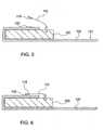
- a second end of the cloth 12is wrapped around the assembly 10, covering the inserted end 16 and overlapping the first end of the cloth 12 (Fig. 3).
- the cloth 12is constructed of multiple layers (not shown) of unreinforced organic dielectric materials which are dimensionally unstable, i.e., susceptible to deformation due to environmental changes, it is difficult to maintain layer-to-layer alignment. As a result, it is difficult to ensure that each layer of the cloth terminates at the end 16, which is necessary in order to make the proper connection with the assembly 10. Likewise, the silver coating at the end 16 is susceptible to electromigration problems, thereby resulting in potential device failure. Furthermore, because the adhesive material on the inner surface of the cloth 10 securely adheres the cloth 12 to the assembly 10 prior to inserting the end 16 into the assembly 10, alignment of the end 16 into the opening 14 of the assembly 10 is often difficult, particularly when the cloth 12 and assembly 10 are slightly misaligned.
- the present inventionprovides, in a first aspect, a security enclosure, comprising: an electronic assembly; a tamper respondent wrap secured at least partially around the assembly; and an extension cable electrically connecting the wrap to the assembly.
- the electronic assemblycomprises a cryptographic processor card.
- the tamper respondent wrapincludes an adhesive inner surface that adheres the wrap to the electronic assembly.
- the tamper respondent wrapfurther includes a plurality of bonding pads formed at a first end of the wrap.
- the tamper respondent wrapfurther includes a system of resistors within each layer of the wrap.
- the system of resistorsconnect ink traces within each layer of the wrap to the bonding pads.
- the extension cablefurther includes a plurality of interconnections at a first end of the extension cable.
- the extension cablefurther includes a plurality of bonding pads at a second end of the extension cable.
- wiresconnect the interconnections and the bonding pads of the extension cable.
- a plurality of bonding pads on the wrapare bonded to a plurality of bonding pads on the extension cable.
- a thermal compression bonding processbonds the bonding pads on the wrap to the bonding pads on the extension cable.
- the wrapat least partially covers the extension cable.
- the extension cablecomprises a flexible dielectric material.
- a security enclosurecomprising: an electronic assembly; an extension, having a first end inserted in the assembly, and a second end having at least one bonding pad thereon; and a tamper respondent wrap at least partially surrounding the assembly, having at least one corresponding bonding pad, wherein the bonding pad of the extension is secured to the bonding pad of the wrap.
- the first end of the extensioncomprises at least one interconnection which forms an electrical connection between the assembly and the extension.
- the at least one interconnectionis electrically connected to the at least one bonding pad of the extension via a wire.
- the wrapfurther includes an adhesive on an inner surface of the wrap to secure the wrap to the assembly.
- the wrapfurther includes a system of resistors connecting ink traces within the wrap to the bonding pads of the wrap.
- the extensioncomprises a flexible cable.
- a security enclosurecomprising: an electronic assembly; and a tamper respondent wrap electrically connected to the assembly via an attachable extension.
- the attachable extensioncomprises a flexible extension cable.
- the tamper respondent wrapcomprises a plurality of bonding pads formed on an end thereof.
- the extensioncomprises a plurality of bonding pads formed on a first end thereof.
- the bonding pads of the wrapare secured to the bonding pads of the extension.
- the extensionfurther comprises a plurality of interconnections formed at a second end of the extension.
- a system of resistorselectrically connects the bonding pads of the wrap to ink traces of the wrap.
- the bonding pads of the wrapare secured to the bonding pads of the extension using a thermal compression bonding process.
- the present inventionprovides a flexible extension for use in a security enclosure, comprising: a first end having a plurality of interconnections which are inserted within an electronic assembly of the enclosure; a second end having a plurality of bonding pads thereon which are secured to a tamper respondent wrap of the enclosure; and wherein the cable electrically connects the wrap and the assembly.
- the bonding pads of the extensionare bonded to bonding pads of the wrap.
- the extensioncomprises a dielectric material.
- the present inventionprovides a method of forming a security enclosure, comprising: providing an electronic assembly having an opening therein; inserting a first end of an extension within the opening of the assembly; wrapping a tamper respondent wrap at least partially around the assembly; and electrically connecting a second end of the extension to the wrap.
- the first aspect of the present inventionthus provides a security enclosure, comprising: an electronic assembly; a tamper respondent wrap secured around the assembly; and an extension cable electrically connecting the cloth to the assembly.
- the present inventionpreferably provides a security enclosure, comprising: an electronic assembly; an extension, having a first end inserted in the assembly, and a second end having at least one bonding pad thereon; and a tamper respondent wrap surrounding the assembly, having at least one corresponding bonding pad, wherein the bonding pad of the extension is secured to the bonding pad of the wrap.
- the present inventionpreferably provides a security enclosure, comprising: an electronic assembly; and a tamper respondent wrap electrically connected to the assembly via an attachable extension.
- the present inventionpreferably provides a flexible extension for use in a security enclosure, comprising: a first end having a plurality of interconnections which are inserted within an electronic assembly of the enclosure; a second end having a plurality of bonding pads thereon which are secured to a tamper respondent wrap of the enclosure; and wherein the cable electrically connects the wrap and the assembly.
- the second aspect of the present inventionthus provides a method of forming a security enclosure, comprising: providing an electronic assembly having an opening therein; inserting a first end of an extension within the opening of the assembly; wrapping a tamper respondent wrap at least partially around the assembly; and connecting a second end of the extension to the wrap.
- Fig. 4shows a cross-sectional view of an electronic assembly 100 in accordance with the present invention.
- the assembly 100typically comprises a cryptographic processor card 102 (shown in phantom), for the storage of key codes required to encrypt and decrypt the secured information, enclosed within a container 106, such as a metal box.
- the extension cable 112is inserted within an opening 114 of the assembly 100.
- the extension cable 112comprises a polyimide dielectric material, such as KaptonTM (DuPont), UpilexTM (UBE), MylarTM (DuPont), or other similar thin flexible dielectric material conventionally used in flex circuitry.
- a cable end 116 located at a first end of the extension cable 112makes electrical connection with the cryptographic processor card 102 within the assembly 100.
- a plurality of bonding pads 118 located at a second end of the extension cable 112makes electrical connection with a cloth (described below).
- the bonding pads 118are formed of copper, having a nickel/gold plating thereon, or other metals, such as silver, etc. The gold provides good conductivity, and the nickel prevents the diffusion of gold into the copper.
- the bonding pads 118may be formed of an electrically conductive thermosetting polymer, or an electrically conductive thermoplastic polymer.
- a tamper respondent wrap or cloth 120is wrapped around the assembly 100, such that a plurality of bonding pads 122 on the cloth 120 align with the plurality of bonding pads 118 on the extension cable 112.
- the cloth 120such as disclosed in the patent to MacPherson (US 5,858,500), is a sheet of composite material comprising a laminate formed of a number of separate layers, including a delamination respondent layer, and a pierce and laser respondent layer. Each layer has a plurality of ink traces or lines (shown in Fig. 9) formed thereon, for the detection of intrusions.
- the linesmay comprise an electrically conductive thermoplastic polymer, electrically conductive thermoset polymer, metal, etc.
- the cloth 112further includes a pressure sensitive adhesive material 121 on the inner surface of the cloth 112, such that the cloth 112 securely adheres to the assembly 100.
- the bonding pads 122are formed of copper, having a nickel/gold plating thereon, or other metals, such as silver, etc. Alternatively, the bonding pads 122 may be formed of an electrically conductive thermosetting polymer, or an electrically conductive thermoplastic polymer.
- the bonding pads 118 of the extension cable 112are secured to the bonding pads 122 of the cloth 120 to complete the electrical connection between the cloth 120 and the assembly 100.
- a thermal compression bonding (TCB) processmay be used in which heat and pressure are applied to the bonding pads 118, 122 until the bonding pads 118, 122 begin to melt and bond together.
- a heater having the correct dimensions corresponding to the size of the bonding pads 118, 122, conventionally used in TCB processing,may also be used to apply heat and pressure directly to the bonding pads 118, 122.
- the specific range of temperatures and pressures necessary to bring the metals, or base polymers within the bonding pads 118, 122 to their melting pointdepends upon the materials selected, and is commonly known in the art.
- the bonding pads 118, 122may be bonded directly to one another using the TCB process described above if the bonding pads 118, 122 are formed of a conductive thermoplastic polymer.
- an additional conductive adhesiveis needed between the bonding pads 118, 122 to bond the pads 118, 122 together.
- an anisotropic conductive tapesuch as 3m 7303TM (3M) may be inserted between the bonding pads 118, 122 prior to performing the TCB process to form the adhesive connection therebetween.
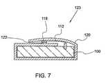
- the remaining portion of the cloth 120is wrapped around the assembly 100, adhering to and covering the extension cable 112 and overlapping the other end of the cloth 120 to form a tightly sealed enclosure 123 (Fig. 7).
- the profile of the assembly 100 and cloth 120is much smoother and flatter than the related art design. This is because a certain amount of slack is required in the cloth of the related art design in order to insert and bend the stiff multiple layers of the cloth, which is not required with the flexible extension cable 112.
- Figs. 8 and 9show greater detail of the extension cable 112 and bonding pads 122 of the cloth 120, respectively, in a top view.
- the cable end 116 at a first end of the extension cable 112includes a plurality of interconnections 124 that mate with and form an electrical connection with the cryptographic processor card 102 inside the assembly 100.
- the interconnections 124are formed of copper with a nickel/gold plating, or other similarly used material.
- Each bonding pad 118has a corresponding interconnection 124.
- Wires 126connect each bonding pad 118 with an interconnection 124.
- Each bonding pad 122 formed on the first end of the cloth 120corresponds to the location of, and aligns with, each bonding pad 118 of the extension cable 112.
- the cloth 120comprises a first or top layer 128 and a second or bottom layer 130. As illustrated, the top layer 128 is partially cut away to remove section 131, thereby exposing the bottom layer 130 for connection to the extension cable 112.
- the top layer 128 of the cloth 120for instance, the pierce and laser respondent layer, has three bonding pads 122a associated therewith.
- a system of connections 132particularly a plurality of resistors formed in parallel and/or series, run throughout the layer 128, (a schematic representation of which is illustrated in Fig. 9), and connect the traces 125 within the layer 128 to the bonding pads 122a.
- the bottom layer 130for instance, the delamination respondent layer, has three bonding pads 122b associated therewith.
- a system of connections 134particularly a plurality of resistors formed in parallel and/or series, run throughout the layer 130, (a graphic representation of which is illustrated in Fig. 9), and connect the traces 125 within the layer 130 to the bonding pads 122b.
- a change in resistance within the system of connections 132, 134indicates a break or short in the traces 125 within the respective layers 128, 130, e.g., caused by an attempted break- in.
- This change in resistanceis detected as a change in voltage drop across the resistor network, which is then relayed to the corresponding bonding pads 122a, 122b of the cloth 120.
- the bonding pads 122a, 122bin turn relay the change in voltage drop to the corresponding bonding pads 118 of the extension cable 112, which then transfers the message through wires 126 and interconnections 124 to the cryptographic processor card 102. Thereafter, the cryptographic processor card 102 may take the appropriate precautions to prevent the information from being divulged, such as erasing the stored key codes for encrypting and decrypting the secured information.
- the extension cable 112provides for easier connection of the cloth 120 to the assembly 100 than with conventional techniques. This is particularly true due to the small size and tight tolerances of the assembly opening 114 and the interconnections 124.
- the extension cable 112also provides a surface large enough to facilitate an automated assembly process.
- the interconnections 124are formed on the extension cable 112 rather than on the end of the cloth 120, the cable end 116 can be inserted in the opening 114 of the assembly 100 without first adhering the cloth 120 to the assembly 100. This reduces the problems associated with proper placement and alignment of the cloth 120.
- slight misalignment of the cloth 120can be compensated for when the extension cable 112 is connected to the cloth 120.
- the cloth 120may be formed of more or less layers than that of the cloth 120 described herein. In which case, a system of connections and corresponding bonding pads would be needed for each layer. Furthermore, the number of bonding pads on each layer, and the corresponding bonding pads on the extension cable, may be varied as needed.
Landscapes
- Engineering & Computer Science (AREA)
- Theoretical Computer Science (AREA)
- Computer Hardware Design (AREA)
- General Physics & Mathematics (AREA)
- Physics & Mathematics (AREA)
- General Engineering & Computer Science (AREA)
- Computer Security & Cryptography (AREA)
- Software Systems (AREA)
- Microelectronics & Electronic Packaging (AREA)
- Human Computer Interaction (AREA)
- Connections Effected By Soldering, Adhesion, Or Permanent Deformation (AREA)
- Communication Cables (AREA)
- Details Of Connecting Devices For Male And Female Coupling (AREA)
Abstract
Description
The present invention relates generally to the detection ofintrusions into security enclosures, and more particularly, to the assemblyof a security enclosure capable of detecting intrusions.
Security enclosures are commonly used in network electronics commerceto transmit encrypted information to authorized persons. Fig. 1 shows arelated art security enclosure 8, comprising anelectronic assembly 10,which typically comprises a cryptographic processor card within anenclosure, and a tamper respondent wrap orcloth 12. Thecloth 12 adheresto theassembly 10 by an adhesive on the inner surface of thecloth 12.Thecloth 12 typically consists of several layers of a flexible dielectrichaving electrical traces or lines (not shown) thereon. Damage to any ofthe traces within a layer produces a change in resistance which prompts thecryptographic processor card to erase the information stored therein.
As illustrated in Fig. 2, a first side of thecloth 12 is wrappedaround theassembly 10. Anend 16 of thecloth 12 is inserted within anopening 14 of theassembly 10. Theend 16 comprises a plurality of silverfilled ink lines formed on the surface of theend 16 to provide anelectrical connection between thecloth 12 and theassembly 10.Thereafter, a second end of thecloth 12 is wrapped around theassembly 10,covering the insertedend 16 and overlapping the first end of the cloth 12(Fig. 3).
Unfortunately, because thecloth 12 is constructed of multiple layers(not shown) of unreinforced organic dielectric materials which aredimensionally unstable, i.e., susceptible to deformation due toenvironmental changes, it is difficult to maintain layer-to-layeralignment. As a result, it is difficult to ensure that each layer of thecloth terminates at theend 16, which is necessary in order to make theproper connection with theassembly 10. Likewise, the silver coating attheend 16 is susceptible to electromigration problems, thereby resultingin potential device failure. Furthermore, because the adhesive material onthe inner surface of thecloth 10 securely adheres thecloth 12 to theassembly 10 prior to inserting theend 16 into theassembly 10, alignmentof theend 16 into theopening 14 of theassembly 10 is often difficult, particularly when thecloth 12 andassembly 10 are slightly misaligned.This may result in device failure due to a poor connection between theend 16 of thecloth 12 and theassembly 10. Likewise, additional forcesexerted on the connection over time due to thermal and mechanical stresses,may further weaken the poor connection producing device failure. Moreover,the process of folding the security cloth and inserting the end into theconnector is not amenable to automation, thus increasing manufacturingcosts. Accordingly, there exists a need in the industry for a securityenclosure that solves these and other problems.
The present invention provides, in a first aspect, a securityenclosure, comprising: an electronic assembly; a tamper respondent wrapsecured at least partially around the assembly; and an extension cableelectrically connecting the wrap to the assembly.
Preferably, the electronic assembly comprises a cryptographicprocessor card.
Preferably, the tamper respondent wrap includes an adhesive innersurface that adheres the wrap to the electronic assembly.
Preferably, the tamper respondent wrap further includes a pluralityof bonding pads formed at a first end of the wrap.
Preferably, the tamper respondent wrap further includes a system ofresistors within each layer of the wrap.
Preferably, the system of resistors connect ink traces within eachlayer of the wrap to the bonding pads.
Preferably, the extension cable further includes a plurality ofinterconnections at a first end of the extension cable.
Preferably, the extension cable further includes a plurality ofbonding pads at a second end of the extension cable.
Preferably, wires connect the interconnections and the bonding padsof the extension cable.
Preferably, a plurality of bonding pads on the wrap are bonded to aplurality of bonding pads on the extension cable.
Preferably, a thermal compression bonding process bonds the bondingpads on the wrap to the bonding pads on the extension cable.
Preferably, the wrap at least partially covers the extension cable.
Preferably, the extension cable comprises a flexible dielectricmaterial.
Preferably, there is provided a security enclosure, comprising: anelectronic assembly; an extension, having a first end inserted in theassembly, and a second end having at least one bonding pad thereon; and atamper respondent wrap at least partially surrounding the assembly, havingat least one corresponding bonding pad, wherein the bonding pad of theextension is secured to the bonding pad of the wrap.
Preferably, the first end of the extension comprises at least oneinterconnection which forms an electrical connection between the assemblyand the extension.
Preferably, the at least one interconnection is electricallyconnected to the at least one bonding pad of the extension via a wire.
Preferably, the wrap further includes an adhesive on an inner surfaceof the wrap to secure the wrap to the assembly.
Preferably, the wrap further includes a system of resistorsconnecting ink traces within the wrap to the bonding pads of the wrap.
Preferably, the extension comprises a flexible cable.
Preferably, there is provided a security enclosure, comprising: anelectronic assembly; and a tamper respondent wrap electrically connected tothe assembly via an attachable extension.
Preferably, the attachable extension comprises a flexible extensioncable.
Preferably, the tamper respondent wrap comprises a plurality ofbonding pads formed on an end thereof.
Preferably, the extension comprises a plurality of bonding padsformed on a first end thereof.
Preferably, the bonding pads of the wrap are secured to the bondingpads of the extension.
Preferably, the extension further comprises a plurality ofinterconnections formed at a second end of the extension.
Preferably, a system of resistors electrically connects the bondingpads of the wrap to ink traces of the wrap.
Preferably, the bonding pads of the wrap are secured to the bondingpads of the extension using a thermal compression bonding process.
Preferably, the present invention provides a flexible extension foruse in a security enclosure, comprising: a first end having a plurality ofinterconnections which are inserted within an electronic assembly of theenclosure; a second end having a plurality of bonding pads thereon whichare secured to a tamper respondent wrap of the enclosure; and wherein thecable electrically connects the wrap and the assembly.
Preferably, the bonding pads of the extension are bonded to bondingpads of the wrap.
Preferably, the extension comprises a dielectric material.
In a second aspect, the present invention provides a method offorming a security enclosure, comprising: providing an electronic assemblyhaving an opening therein; inserting a first end of an extension within theopening of the assembly; wrapping a tamper respondent wrap at leastpartially around the assembly; and electrically connecting a second end ofthe extension to the wrap.
The first aspect of the present invention thus provides a securityenclosure, comprising: an electronic assembly; a tamper respondent wrapsecured around the assembly; and an extension cable electrically connectingthe cloth to the assembly.
The present invention preferably provides a security enclosure,comprising: an electronic assembly; an extension, having a first endinserted in the assembly, and a second end having at least one bonding padthereon; and a tamper respondent wrap surrounding the assembly, having atleast one corresponding bonding pad, wherein the bonding pad of theextension is secured to the bonding pad of the wrap.
The present invention preferably provides a security enclosure,comprising: an electronic assembly; and a tamper respondent wrapelectrically connected to the assembly via an attachable extension.
The present invention preferably provides a flexible extension foruse in a security enclosure, comprising: a first end having a plurality ofinterconnections which are inserted within an electronic assembly of theenclosure; a second end having a plurality of bonding pads thereon whichare secured to a tamper respondent wrap of the enclosure; and wherein thecable electrically connects the wrap and the assembly.
The second aspect of the present invention thus provides a method offorming a security enclosure, comprising: providing an electronic assemblyhaving an opening therein; inserting a first end of an extension within theopening of the assembly; wrapping a tamper respondent wrap at leastpartially around the assembly; and connecting a second end of the extensionto the wrap.
Preferred embodiments of the present invention will now be providedby way of example only, with reference to the accompanying drawings, inwhich:
Although certain embodiments of the present invention will be shownand described in detail, it should be understood that various changes andmodifications may be made without departing from the scope of the appendedclaims. The scope of the present invention need in no way be limited tothe number of constituting components, the materials thereof, the shapesthereof, the relative arrangement thereof, etc. Although the drawings areintended to illustrate the present invention, the drawings are notnecessarily drawn to scale.
Referring to the drawings, Fig. 4 shows a cross-sectional view of anelectronic assembly 100 in accordance with the present invention. Theassembly 100 typically comprises a cryptographic processor card 102 (shownin phantom), for the storage of key codes required to encrypt and decryptthe secured information, enclosed within acontainer 106, such as a metalbox.
Anextension cable 112 is inserted within anopening 114 of theassembly 100. Theextension cable 112 comprises a polyimide dielectricmaterial, such as Kapton™ (DuPont), Upilex™ (UBE), Mylar™ (DuPont), orother similar thin flexible dielectric material conventionally used in flexcircuitry. In particular, acable end 116 located at a first end of theextension cable 112 makes electrical connection with thecryptographicprocessor card 102 within theassembly 100. A plurality ofbonding pads 118 located at a second end of theextension cable 112 makes electricalconnection with a cloth (described below). Thebonding pads 118 are formedof copper, having a nickel/gold plating thereon, or other metals, such assilver, etc. The gold provides good conductivity, and the nickel preventsthe diffusion of gold into the copper. Alternatively, thebonding pads 118may be formed of an electrically conductive thermosetting polymer, or anelectrically conductive thermoplastic polymer.
As illustrated in Fig. 5, a tamper respondent wrap orcloth 120 iswrapped around theassembly 100, such that a plurality ofbonding pads 122on thecloth 120 align with the plurality ofbonding pads 118 on theextension cable 112. Thecloth 120, such as disclosed in the patent toMacPherson (US 5,858,500), is a sheet of composite material comprising a laminate formed of a number of separate layers, including a delaminationrespondent layer, and a pierce and laser respondent layer. Each layer hasa plurality of ink traces or lines (shown in Fig. 9) formed thereon, forthe detection of intrusions. The lines may comprise an electricallyconductive thermoplastic polymer, electrically conductive thermosetpolymer, metal, etc. Thecloth 112 further includes a pressure sensitiveadhesive material 121 on the inner surface of thecloth 112, such that thecloth 112 securely adheres to theassembly 100. Thebonding pads 122 areformed of copper, having a nickel/gold plating thereon, or other metals,such as silver, etc. Alternatively, thebonding pads 122 may be formed ofan electrically conductive thermosetting polymer, or an electricallyconductive thermoplastic polymer.
As illustrated in Fig. 6, thebonding pads 118 of theextension cable 112 are secured to thebonding pads 122 of thecloth 120 to complete theelectrical connection between thecloth 120 and theassembly 100. Athermal compression bonding (TCB) process may be used in which heat andpressure are applied to thebonding pads bonding pads bonding pads bonding pads bonding pads
Thebonding pads bonding pads bonding pads bonding pads pads bonding pads
Thereafter, the remaining portion of thecloth 120 is wrapped aroundtheassembly 100, adhering to and covering theextension cable 112 andoverlapping the other end of thecloth 120 to form a tightly sealedenclosure 123 (Fig. 7). It should be noted that due to the flexible natureof theextension cable 112, the profile of theassembly 100 andcloth 120is much smoother and flatter than the related art design. This is becausea certain amount of slack is required in the cloth of the related artdesign in order to insert and bend the stiff multiple layers of the cloth,which is not required with theflexible extension cable 112.
Figs. 8 and 9 show greater detail of theextension cable 112 andbonding pads 122 of thecloth 120, respectively, in a top view. Inparticular, thecable end 116 at a first end of theextension cable 112includes a plurality ofinterconnections 124 that mate with and form anelectrical connection with thecryptographic processor card 102 inside theassembly 100. Theinterconnections 124 are formed of copper with anickel/gold plating, or other similarly used material. Eachbonding pad 118 has acorresponding interconnection 124.Wires 126 connect eachbonding pad 118 with aninterconnection 124.
Eachbonding pad 122 formed on the first end of thecloth 120corresponds to the location of, and aligns with, eachbonding pad 118 oftheextension cable 112. In this example, thecloth 120 comprises a firstortop layer 128 and a second orbottom layer 130. As illustrated, thetoplayer 128 is partially cut away to removesection 131, thereby exposing thebottom layer 130 for connection to theextension cable 112.
In this example, thetop layer 128 of thecloth 120, for instance,the pierce and laser respondent layer, has threebonding pads 122aassociated therewith. A system ofconnections 132, particularly aplurality of resistors formed in parallel and/or series, run throughout thelayer 128, (a schematic representation of which is illustrated in Fig. 9),and connect thetraces 125 within thelayer 128 to thebonding pads 122a.Similarly, thebottom layer 130, for instance, the delamination respondentlayer, has threebonding pads 122b associated therewith. A system ofconnections 134, particularly a plurality of resistors formed in paralleland/or series, run throughout thelayer 130, (a graphic representation ofwhich is illustrated in Fig. 9), and connect thetraces 125 within thelayer 130 to thebonding pads 122b.
A change in resistance within the system ofconnections traces 125 within therespective layers corresponding bonding pads cloth 120. Thebonding pads corresponding bonding pads 118 of theextension cable 112, which then transfers the message throughwires 126 andinterconnections 124 to thecryptographic processor card 102. Thereafter,thecryptographic processor card 102 may take the appropriate precautionsto prevent the information from being divulged, such as erasing the storedkey codes for encrypting and decrypting the secured information.
Theextension cable 112 provides for easier connection of thecloth 120 to theassembly 100 than with conventional techniques. This isparticularly true due to the small size and tight tolerances of theassembly opening 114 and theinterconnections 124. Theextension cable 112also provides a surface large enough to facilitate an automated assemblyprocess. Likewise, because theinterconnections 124 are formed on theextension cable 112 rather than on the end of thecloth 120, thecable end 116 can be inserted in theopening 114 of theassembly 100 without firstadhering thecloth 120 to theassembly 100. This reduces the problemsassociated with proper placement and alignment of thecloth 120. Also, dueto the flexible nature of theextension cable 112, slight misalignment ofthecloth 120 can be compensated for when theextension cable 112 isconnected to thecloth 120. In fact, misalignment of several millimetersmay be tolerable between thebonding pads interconnections 124 are formed of copper with a nickel/gold plating,rather than silver ink, the electromigration problems are minimized.
It should be noted that the embodiments disclosed above are notintended to limit the scope of the present invention in any way. Forinstance, thecloth 120 may be formed of more or less layers than that ofthecloth 120 described herein. In which case, a system of connections andcorresponding bonding pads would be needed for each layer. Furthermore,the number of bonding pads on each layer, and the corresponding bondingpads on the extension cable, may be varied as needed.
While this invention has been described in conjunction with thespecific embodiments outlined above, it is evident that many alternatives,modifications and variations will be apparent to those skilled in the art.Accordingly, the embodiments of the invention as set forth above areintended to be illustrative, not limiting. Various changes may be madewithout departing from the scope of the invention as defined in thefollowing claims.
Claims (14)
- A security enclosure, comprising:an electronic assembly;a tamper respondent wrap secured at least partially around theassembly; andan extension cable electrically connecting the wrap to the assembly.
- A security enclosure as claimed in claim 1, wherein the electronicassembly comprises a cryptographic processor card.
- A security enclosure as claimed in claim 1 or claim 2, wherein thetamper respondent wrap includes an adhesive inner surface that adheres thewrap to the electronic assembly.
- A security enclosure as claimed in any of claims 1 to 3, wherein thetamper respondent wrap further includes a plurality of bonding pads formedat a first end of the wrap.
- A security enclosure as claimed in claim 4, wherein the tamperrespondent wrap further includes a system of resistors within each layer ofthe wrap.
- A security enclosure as claimed in claim 5, wherein the system ofresistors connect ink traces within each layer of the wrap to the bondingpads.
- A security enclosure as claimed in any preceding claim, wherein theextension cable further includes a plurality of interconnections at afirst end of the extension cable.
- A security enclosure as claimed in claim 7, wherein the extensioncable further includes a plurality of bonding pads at a second end of theextension cable.
- A security enclosure as claimed in claim 8, wherein wires connect theinterconnections and the bonding pads of the extension cable.
- A security enclosure as claimed in any preceding claim, wherein aplurality of bonding pads on the wrap are bonded to a plurality of bondingpads on the extension cable.
- A security enclosure as claimed in claim 10, wherein a thermalcompression bonding process bonds the bonding pads on the wrap to thebonding pads on the extension cable.
- A security enclosure as claimed in any preceding claim, wherein thewrap at least partially covers the extension cable.
- A security enclosure as claimed in any preceding claim, wherein theextension cable comprises a flexible dielectric material.
- A method of forming a security enclosure, comprising:providing an electronic assembly having an opening therein;inserting a first end of an extension within the opening of theassembly;wrapping a tamper respondent wrap at least partially around theassembly; andelectrically connecting a second end of the extension to the wrap.
Applications Claiming Priority (2)
| Application Number | Priority Date | Filing Date | Title |
|---|---|---|---|
| US717698 | 1991-06-20 | ||
| US09/717,698US6982642B1 (en) | 2000-11-20 | 2000-11-20 | Security cloth design and assembly |
Publications (2)
| Publication Number | Publication Date |
|---|---|
| EP1207444A2true EP1207444A2 (en) | 2002-05-22 |
| EP1207444A3 EP1207444A3 (en) | 2004-12-22 |
Family
ID=24883094
Family Applications (1)
| Application Number | Title | Priority Date | Filing Date |
|---|---|---|---|
| EP01309696AWithdrawnEP1207444A3 (en) | 2000-11-20 | 2001-11-16 | Security cloth design and assembly |
Country Status (4)
| Country | Link |
|---|---|
| US (2) | US6982642B1 (en) |
| EP (1) | EP1207444A3 (en) |
| KR (1) | KR100621440B1 (en) |
| CA (1) | CA2358743A1 (en) |
Cited By (33)
| Publication number | Priority date | Publication date | Assignee | Title |
|---|---|---|---|---|
| US6895509B1 (en) | 2000-09-21 | 2005-05-17 | Pitney Bowes Inc. | Tamper detection system for securing data |
| US6996953B2 (en) | 2004-01-23 | 2006-02-14 | Pitney Bowes Inc. | System and method for installing a tamper barrier wrap in a PCB assembly, including a PCB assembly having improved heat sinking |
| US7156233B2 (en) | 2004-06-15 | 2007-01-02 | Pitney Bowes Inc. | Tamper barrier enclosure with corner protection |
| US7180008B2 (en) | 2004-01-23 | 2007-02-20 | Pitney Bowes Inc. | Tamper barrier for electronic device |
| CN100423354C (en)* | 2004-03-30 | 2008-10-01 | 三星Sdi株式会社 | Can-shaped lithium-ion secondary battery |
| US9554477B1 (en) | 2015-12-18 | 2017-01-24 | International Business Machines Corporation | Tamper-respondent assemblies with enclosure-to-board protection |
| US9560737B2 (en) | 2015-03-04 | 2017-01-31 | International Business Machines Corporation | Electronic package with heat transfer element(s) |
| US9555606B1 (en) | 2015-12-09 | 2017-01-31 | International Business Machines Corporation | Applying pressure to adhesive using CTE mismatch between components |
| US9578764B1 (en) | 2015-09-25 | 2017-02-21 | International Business Machines Corporation | Enclosure with inner tamper-respondent sensor(s) and physical security element(s) |
| US9591776B1 (en) | 2015-09-25 | 2017-03-07 | International Business Machines Corporation | Enclosure with inner tamper-respondent sensor(s) |
| US9858776B1 (en) | 2016-06-28 | 2018-01-02 | International Business Machines Corporation | Tamper-respondent assembly with nonlinearity monitoring |
| US9881880B2 (en) | 2016-05-13 | 2018-01-30 | International Business Machines Corporation | Tamper-proof electronic packages with stressed glass component substrate(s) |
| US9894749B2 (en) | 2015-09-25 | 2018-02-13 | International Business Machines Corporation | Tamper-respondent assemblies with bond protection |
| US9904811B2 (en) | 2016-04-27 | 2018-02-27 | International Business Machines Corporation | Tamper-proof electronic packages with two-phase dielectric fluid |
| US9913389B2 (en) | 2015-12-01 | 2018-03-06 | International Business Corporation Corporation | Tamper-respondent assembly with vent structure |
| US9911012B2 (en) | 2015-09-25 | 2018-03-06 | International Business Machines Corporation | Overlapping, discrete tamper-respondent sensors |
| US9913370B2 (en) | 2016-05-13 | 2018-03-06 | International Business Machines Corporation | Tamper-proof electronic packages formed with stressed glass |
| US9916744B2 (en) | 2016-02-25 | 2018-03-13 | International Business Machines Corporation | Multi-layer stack with embedded tamper-detect protection |
| US9924591B2 (en) | 2015-09-25 | 2018-03-20 | International Business Machines Corporation | Tamper-respondent assemblies |
| US9978231B2 (en) | 2015-10-21 | 2018-05-22 | International Business Machines Corporation | Tamper-respondent assembly with protective wrap(s) over tamper-respondent sensor(s) |
| US9999124B2 (en) | 2016-11-02 | 2018-06-12 | International Business Machines Corporation | Tamper-respondent assemblies with trace regions of increased susceptibility to breaking |
| US10098235B2 (en) | 2015-09-25 | 2018-10-09 | International Business Machines Corporation | Tamper-respondent assemblies with region(s) of increased susceptibility to damage |
| US10136519B2 (en) | 2015-10-19 | 2018-11-20 | International Business Machines Corporation | Circuit layouts of tamper-respondent sensors |
| US10168185B2 (en) | 2015-09-25 | 2019-01-01 | International Business Machines Corporation | Circuit boards and electronic packages with embedded tamper-respondent sensor |
| US10172239B2 (en) | 2015-09-25 | 2019-01-01 | International Business Machines Corporation | Tamper-respondent sensors with formed flexible layer(s) |
| US10271424B2 (en) | 2016-09-26 | 2019-04-23 | International Business Machines Corporation | Tamper-respondent assemblies with in situ vent structure(s) |
| US10299372B2 (en) | 2016-09-26 | 2019-05-21 | International Business Machines Corporation | Vented tamper-respondent assemblies |
| US10306753B1 (en) | 2018-02-22 | 2019-05-28 | International Business Machines Corporation | Enclosure-to-board interface with tamper-detect circuit(s) |
| US10321589B2 (en) | 2016-09-19 | 2019-06-11 | International Business Machines Corporation | Tamper-respondent assembly with sensor connection adapter |
| US10327343B2 (en) | 2015-12-09 | 2019-06-18 | International Business Machines Corporation | Applying pressure to adhesive using CTE mismatch between components |
| US10327329B2 (en) | 2017-02-13 | 2019-06-18 | International Business Machines Corporation | Tamper-respondent assembly with flexible tamper-detect sensor(s) overlying in-situ-formed tamper-detect sensor |
| US10426037B2 (en) | 2015-07-15 | 2019-09-24 | International Business Machines Corporation | Circuitized structure with 3-dimensional configuration |
| US11122682B2 (en) | 2018-04-04 | 2021-09-14 | International Business Machines Corporation | Tamper-respondent sensors with liquid crystal polymer layers |
Families Citing this family (13)
| Publication number | Priority date | Publication date | Assignee | Title |
|---|---|---|---|---|
| US7772974B2 (en)* | 2005-02-28 | 2010-08-10 | Cypak Ab | Tamper evident seal system and method |
| US7535373B2 (en)* | 2005-07-15 | 2009-05-19 | Honeywell International, Inc. | Security techniques for electronic devices |
| US7640658B1 (en)* | 2005-10-18 | 2010-01-05 | Teledyne Technologies Incorporated | Methods for forming an anti-tamper pattern |
| US9015075B2 (en)* | 2006-09-29 | 2015-04-21 | Oracle America, Inc. | Method and apparatus for secure information distribution |
| US7760086B2 (en)* | 2006-11-03 | 2010-07-20 | Gore Enterprise Holdings, Inc | Tamper respondent sensor and enclosure |
| JP4957220B2 (en)* | 2006-12-04 | 2012-06-20 | 株式会社デンソー | Electronic package |
| US8201267B2 (en)* | 2008-10-24 | 2012-06-12 | Pitney Bowes Inc. | Cryptographic device having active clearing of memory regardless of state of external power |
| US8325486B2 (en) | 2009-01-13 | 2012-12-04 | Dy 4 Systems Inc. | Tamper respondent module |
| US8818478B2 (en)* | 2011-03-31 | 2014-08-26 | Adidas Ag | Sensor garment |
| US20140041060A1 (en)* | 2012-07-31 | 2014-02-06 | Keymat Technology Limited | Keypad Device |
| US9392734B1 (en) | 2014-02-11 | 2016-07-12 | Lockheed Martin Corporation | Security wrapper for an electronic assembly and methods for forming such a wrapper |
| US9565777B1 (en) | 2015-12-15 | 2017-02-07 | International Business Machines Corporation | Security mesh and method of making |
| US11709972B2 (en)* | 2020-02-21 | 2023-07-25 | Te Connectivity Solutions Gmbh | Substrate for a tamper sensor |
Family Cites Families (25)
| Publication number | Priority date | Publication date | Assignee | Title |
|---|---|---|---|---|
| DE7422135U (en) | 1974-06-28 | 1974-11-14 | Raychem Gmbh | Ribbon line with branch lines |
| US4028794A (en) | 1974-09-09 | 1977-06-14 | Amp Incorporated | Laminated connector |
| US4589584A (en) | 1985-01-31 | 1986-05-20 | International Business Machines Corporation | Electrical connection for polymeric conductive material |
| US4722692A (en) | 1986-01-06 | 1988-02-02 | Minnesota Mining And Manufacturing Company | Cable termination assembly, nipping and knuckling machine, and method |
| JPH055657Y2 (en) | 1988-05-10 | 1993-02-15 | ||
| GB8814471D0 (en)* | 1988-06-17 | 1988-07-20 | Gore & Ass | Security enclosure |
| US5239664A (en) | 1988-12-20 | 1993-08-24 | Bull S.A. | Arrangement for protecting an electronic card and its use for protecting a terminal for reading magnetic and/or microprocessor cards |
| US5027397A (en) | 1989-09-12 | 1991-06-25 | International Business Machines Corporation | Data protection by detection of intrusion into electronic assemblies |
| US5136643A (en)* | 1989-10-13 | 1992-08-04 | Fischer Addison M | Public/key date-time notary facility |
| GB9113455D0 (en)* | 1991-06-21 | 1991-08-07 | Gore W L & Ass Uk | Improvements in security enclosures |
| GB9113437D0 (en) | 1991-06-21 | 1991-08-07 | Gore W L & Ass Uk | Improvements in security enclosures |
| GB9115972D0 (en)* | 1991-07-24 | 1991-09-11 | Gore W L & Ass Uk | Improvements in security enclosures |
| US5186632A (en) | 1991-09-20 | 1993-02-16 | International Business Machines Corporation | Electronic device elastomeric mounting and interconnection technology |
| US5389738A (en) | 1992-05-04 | 1995-02-14 | Motorola, Inc. | Tamperproof arrangement for an integrated circuit device |
| GB2270785B (en)* | 1992-09-22 | 1996-05-08 | Gore & Ass | Improvements in security enclosure manufacture |
| GB2275914B (en) | 1993-03-12 | 1997-01-29 | Gore & Ass | Tamper respondent enclosure |
| FR2746962B1 (en) | 1996-04-01 | 1998-04-30 | Schlumberger Ind Sa | SECURITY DEVICE OF A SEMICONDUCTOR PELLET |
| US5675319A (en) | 1996-04-26 | 1997-10-07 | David Sarnoff Research Center, Inc. | Tamper detection device |
| US5861662A (en) | 1997-02-24 | 1999-01-19 | General Instrument Corporation | Anti-tamper bond wire shield for an integrated circuit |
| US6084380A (en)* | 1998-11-02 | 2000-07-04 | Hewlett-Packard Company | Conforming intelligent battery label |
| EP1045352A1 (en) | 1999-04-14 | 2000-10-18 | W L Gore & Associares S.r.l. | Enclosure |
| US7007171B1 (en)* | 2000-09-01 | 2006-02-28 | International Business Machines Corporaton | Method and apparatus for improved fold retention on a security enclosure |
| US6686539B2 (en)* | 2001-01-03 | 2004-02-03 | International Business Machines Corporation | Tamper-responding encapsulated enclosure having flexible protective mesh structure |
| US7180008B2 (en)* | 2004-01-23 | 2007-02-20 | Pitney Bowes Inc. | Tamper barrier for electronic device |
| US7323986B2 (en)* | 2004-09-03 | 2008-01-29 | Gore Enterprise Holdings, Inc. | Reusable tamper respondent enclosure |
- 2000
- 2000-11-20USUS09/717,698patent/US6982642B1/ennot_activeExpired - Fee Related
- 2001
- 2001-10-12CACA002358743Apatent/CA2358743A1/ennot_activeAbandoned
- 2001-11-07KRKR1020010069123Apatent/KR100621440B1/ennot_activeExpired - Fee Related
- 2001-11-16EPEP01309696Apatent/EP1207444A3/ennot_activeWithdrawn
- 2005
- 2005-11-04USUS11/267,770patent/US7679921B2/ennot_activeExpired - Fee Related
Cited By (59)
| Publication number | Priority date | Publication date | Assignee | Title |
|---|---|---|---|---|
| US6895509B1 (en) | 2000-09-21 | 2005-05-17 | Pitney Bowes Inc. | Tamper detection system for securing data |
| US6996953B2 (en) | 2004-01-23 | 2006-02-14 | Pitney Bowes Inc. | System and method for installing a tamper barrier wrap in a PCB assembly, including a PCB assembly having improved heat sinking |
| US7180008B2 (en) | 2004-01-23 | 2007-02-20 | Pitney Bowes Inc. | Tamper barrier for electronic device |
| US7475474B2 (en) | 2004-01-23 | 2009-01-13 | Pitney Bowes Inc. | Method of making tamper detection circuit for an electronic device |
| CN100423354C (en)* | 2004-03-30 | 2008-10-01 | 三星Sdi株式会社 | Can-shaped lithium-ion secondary battery |
| US7156233B2 (en) | 2004-06-15 | 2007-01-02 | Pitney Bowes Inc. | Tamper barrier enclosure with corner protection |
| US10237964B2 (en) | 2015-03-04 | 2019-03-19 | International Business Machines Corporation | Manufacturing electronic package with heat transfer element(s) |
| US9560737B2 (en) | 2015-03-04 | 2017-01-31 | International Business Machines Corporation | Electronic package with heat transfer element(s) |
| US10524362B2 (en) | 2015-07-15 | 2019-12-31 | International Business Machines Corporation | Circuitized structure with 3-dimensional configuration |
| US10426037B2 (en) | 2015-07-15 | 2019-09-24 | International Business Machines Corporation | Circuitized structure with 3-dimensional configuration |
| US9911012B2 (en) | 2015-09-25 | 2018-03-06 | International Business Machines Corporation | Overlapping, discrete tamper-respondent sensors |
| US9936573B2 (en) | 2015-09-25 | 2018-04-03 | International Business Machines Corporation | Tamper-respondent assemblies |
| US9717154B2 (en) | 2015-09-25 | 2017-07-25 | International Business Machines Corporation | Enclosure with inner tamper-respondent sensor(s) |
| US10624202B2 (en) | 2015-09-25 | 2020-04-14 | International Business Machines Corporation | Tamper-respondent assemblies with bond protection |
| US10264665B2 (en) | 2015-09-25 | 2019-04-16 | International Business Machines Corporation | Tamper-respondent assemblies with bond protection |
| US9591776B1 (en) | 2015-09-25 | 2017-03-07 | International Business Machines Corporation | Enclosure with inner tamper-respondent sensor(s) |
| US9894749B2 (en) | 2015-09-25 | 2018-02-13 | International Business Machines Corporation | Tamper-respondent assemblies with bond protection |
| US9578764B1 (en) | 2015-09-25 | 2017-02-21 | International Business Machines Corporation | Enclosure with inner tamper-respondent sensor(s) and physical security element(s) |
| US9913416B2 (en) | 2015-09-25 | 2018-03-06 | International Business Machines Corporation | Enclosure with inner tamper-respondent sensor(s) and physical security element(s) |
| US10175064B2 (en) | 2015-09-25 | 2019-01-08 | International Business Machines Corporation | Circuit boards and electronic packages with embedded tamper-respondent sensor |
| US10257939B2 (en) | 2015-09-25 | 2019-04-09 | International Business Machines Corporation | Method of fabricating tamper-respondent sensor |
| US10395067B2 (en) | 2015-09-25 | 2019-08-27 | International Business Machines Corporation | Method of fabricating a tamper-respondent sensor assembly |
| US9913362B2 (en) | 2015-09-25 | 2018-03-06 | International Business Machines Corporation | Tamper-respondent assemblies with bond protection |
| US10331915B2 (en) | 2015-09-25 | 2019-06-25 | International Business Machines Corporation | Overlapping, discrete tamper-respondent sensors |
| US9924591B2 (en) | 2015-09-25 | 2018-03-20 | International Business Machines Corporation | Tamper-respondent assemblies |
| US10178818B2 (en) | 2015-09-25 | 2019-01-08 | International Business Machines Corporation | Enclosure with inner tamper-respondent sensor(s) and physical security element(s) |
| US10271434B2 (en) | 2015-09-25 | 2019-04-23 | International Business Machines Corporation | Method of fabricating a tamper-respondent assembly with region(s) of increased susceptibility to damage |
| US10334722B2 (en) | 2015-09-25 | 2019-06-25 | International Business Machines Corporation | Tamper-respondent assemblies |
| US10098235B2 (en) | 2015-09-25 | 2018-10-09 | International Business Machines Corporation | Tamper-respondent assemblies with region(s) of increased susceptibility to damage |
| US10172239B2 (en) | 2015-09-25 | 2019-01-01 | International Business Machines Corporation | Tamper-respondent sensors with formed flexible layer(s) |
| US10168185B2 (en) | 2015-09-25 | 2019-01-01 | International Business Machines Corporation | Circuit boards and electronic packages with embedded tamper-respondent sensor |
| US10143090B2 (en) | 2015-10-19 | 2018-11-27 | International Business Machines Corporation | Circuit layouts of tamper-respondent sensors |
| US10136519B2 (en) | 2015-10-19 | 2018-11-20 | International Business Machines Corporation | Circuit layouts of tamper-respondent sensors |
| US9978231B2 (en) | 2015-10-21 | 2018-05-22 | International Business Machines Corporation | Tamper-respondent assembly with protective wrap(s) over tamper-respondent sensor(s) |
| US9913389B2 (en) | 2015-12-01 | 2018-03-06 | International Business Corporation Corporation | Tamper-respondent assembly with vent structure |
| US10251288B2 (en) | 2015-12-01 | 2019-04-02 | International Business Machines Corporation | Tamper-respondent assembly with vent structure |
| US10327343B2 (en) | 2015-12-09 | 2019-06-18 | International Business Machines Corporation | Applying pressure to adhesive using CTE mismatch between components |
| US9555606B1 (en) | 2015-12-09 | 2017-01-31 | International Business Machines Corporation | Applying pressure to adhesive using CTE mismatch between components |
| US10172232B2 (en) | 2015-12-18 | 2019-01-01 | International Business Machines Corporation | Tamper-respondent assemblies with enclosure-to-board protection |
| US9661747B1 (en) | 2015-12-18 | 2017-05-23 | International Business Machines Corporation | Tamper-respondent assemblies with enclosure-to-board protection |
| US9554477B1 (en) | 2015-12-18 | 2017-01-24 | International Business Machines Corporation | Tamper-respondent assemblies with enclosure-to-board protection |
| US9877383B2 (en) | 2015-12-18 | 2018-01-23 | International Business Machines Corporation | Tamper-respondent assemblies with enclosure-to-board protection |
| US10115275B2 (en) | 2016-02-25 | 2018-10-30 | International Business Machines Corporation | Multi-layer stack with embedded tamper-detect protection |
| US9916744B2 (en) | 2016-02-25 | 2018-03-13 | International Business Machines Corporation | Multi-layer stack with embedded tamper-detect protection |
| US10169624B2 (en) | 2016-04-27 | 2019-01-01 | International Business Machines Corporation | Tamper-proof electronic packages with two-phase dielectric fluid |
| US9904811B2 (en) | 2016-04-27 | 2018-02-27 | International Business Machines Corporation | Tamper-proof electronic packages with two-phase dielectric fluid |
| US10177102B2 (en) | 2016-05-13 | 2019-01-08 | International Business Machines Corporation | Tamper-proof electronic packages with stressed glass component substrate(s) |
| US10257924B2 (en) | 2016-05-13 | 2019-04-09 | International Business Machines Corporation | Tamper-proof electronic packages formed with stressed glass |
| US9881880B2 (en) | 2016-05-13 | 2018-01-30 | International Business Machines Corporation | Tamper-proof electronic packages with stressed glass component substrate(s) |
| US9913370B2 (en) | 2016-05-13 | 2018-03-06 | International Business Machines Corporation | Tamper-proof electronic packages formed with stressed glass |
| US10242543B2 (en) | 2016-06-28 | 2019-03-26 | International Business Machines Corporation | Tamper-respondent assembly with nonlinearity monitoring |
| US9858776B1 (en) | 2016-06-28 | 2018-01-02 | International Business Machines Corporation | Tamper-respondent assembly with nonlinearity monitoring |
| US10321589B2 (en) | 2016-09-19 | 2019-06-11 | International Business Machines Corporation | Tamper-respondent assembly with sensor connection adapter |
| US10299372B2 (en) | 2016-09-26 | 2019-05-21 | International Business Machines Corporation | Vented tamper-respondent assemblies |
| US10271424B2 (en) | 2016-09-26 | 2019-04-23 | International Business Machines Corporation | Tamper-respondent assemblies with in situ vent structure(s) |
| US9999124B2 (en) | 2016-11-02 | 2018-06-12 | International Business Machines Corporation | Tamper-respondent assemblies with trace regions of increased susceptibility to breaking |
| US10327329B2 (en) | 2017-02-13 | 2019-06-18 | International Business Machines Corporation | Tamper-respondent assembly with flexible tamper-detect sensor(s) overlying in-situ-formed tamper-detect sensor |
| US10306753B1 (en) | 2018-02-22 | 2019-05-28 | International Business Machines Corporation | Enclosure-to-board interface with tamper-detect circuit(s) |
| US11122682B2 (en) | 2018-04-04 | 2021-09-14 | International Business Machines Corporation | Tamper-respondent sensors with liquid crystal polymer layers |
Also Published As
| Publication number | Publication date |
|---|---|
| US20060080348A1 (en) | 2006-04-13 |
| KR100621440B1 (en) | 2006-09-07 |
| US6982642B1 (en) | 2006-01-03 |
| CA2358743A1 (en) | 2002-05-20 |
| US7679921B2 (en) | 2010-03-16 |
| EP1207444A3 (en) | 2004-12-22 |
| KR20020039234A (en) | 2002-05-25 |
Similar Documents
| Publication | Publication Date | Title |
|---|---|---|
| US6982642B1 (en) | Security cloth design and assembly | |
| US7007171B1 (en) | Method and apparatus for improved fold retention on a security enclosure | |
| US10178818B2 (en) | Enclosure with inner tamper-respondent sensor(s) and physical security element(s) | |
| EP0488574B1 (en) | Personal data card construction | |
| CN108027869B (en) | Tamper-respondent sensor with shaped flexible layer | |
| US10264665B2 (en) | Tamper-respondent assemblies with bond protection | |
| US9555606B1 (en) | Applying pressure to adhesive using CTE mismatch between components | |
| US10327343B2 (en) | Applying pressure to adhesive using CTE mismatch between components | |
| US10334722B2 (en) | Tamper-respondent assemblies | |
| US6803114B1 (en) | Manufacturing process for laminated cards with intermediate PETG layer | |
| US10098235B2 (en) | Tamper-respondent assemblies with region(s) of increased susceptibility to damage | |
| US9224280B2 (en) | Security wrap | |
| JP2018531446A6 (en) | Tamper-open sensor with a formed flexible layer | |
| JPH02220896A (en) | Electronic module for small portable object such as card or key having integrated circuit and manufacture thereof | |
| CN103582298A (en) | Security wrap | |
| JP2018530056A (en) | Circuit board and electronic package including embedded tamper sensitive sensor | |
| CN1998080A (en) | Tamper respondent covering | |
| US8040281B2 (en) | Radiofrequency device | |
| CN101248436B (en) | Hardware protection in form of printed circuit board drawn into semi-case | |
| JP4287378B2 (en) | Smart card including accessible components and method of manufacturing the same | |
| JPH09286187A (en) | IC card, intermediate for manufacturing IC card, and method for manufacturing IC card | |
| US11765816B2 (en) | Tamper-respondent assemblies with pressure connector assemblies | |
| JP4028164B2 (en) | IC card | |
| CN1797269A (en) | Device for protecting a data storage circuit arrangement comprising electronic components and a processor | |
| JP2002197433A (en) | IC card and manufacturing method thereof |
Legal Events
| Date | Code | Title | Description |
|---|---|---|---|
| PUAI | Public reference made under article 153(3) epc to a published international application that has entered the european phase | Free format text:ORIGINAL CODE: 0009012 | |
| AX | Request for extension of the european patent | Free format text:AL;LT;LV;MK;RO;SI | |
| PUAL | Search report despatched | Free format text:ORIGINAL CODE: 0009013 | |
| AK | Designated contracting states | Kind code of ref document:A3 Designated state(s):AT BE CH CY DE DK ES FI FR GB GR IE IT LI LU MC NL PT SE TR | |
| AX | Request for extension of the european patent | Extension state:AL LT LV MK RO SI | |
| 17P | Request for examination filed | Effective date:20050203 | |
| 17Q | First examination report despatched | Effective date:20050517 | |
| AKX | Designation fees paid | Designated state(s):AT BE CH CY DE DK ES FI FR GB GR IE IT LI LU MC NL PT SE TR | |
| STAA | Information on the status of an ep patent application or granted ep patent | Free format text:STATUS: THE APPLICATION IS DEEMED TO BE WITHDRAWN | |
| 18D | Application deemed to be withdrawn | Effective date:20050928 |