EP1206843B1 - Adaptive channel estimation in a wireless communication system - Google Patents
Adaptive channel estimation in a wireless communication systemDownload PDFInfo
- Publication number
- EP1206843B1 EP1206843B1EP00954139AEP00954139AEP1206843B1EP 1206843 B1EP1206843 B1EP 1206843B1EP 00954139 AEP00954139 AEP 00954139AEP 00954139 AEP00954139 AEP 00954139AEP 1206843 B1EP1206843 B1EP 1206843B1
- Authority
- EP
- European Patent Office
- Prior art keywords
- channel
- pilot
- signal
- power control
- sign
- Prior art date
- Legal status (The legal status is an assumption and is not a legal conclusion. Google has not performed a legal analysis and makes no representation as to the accuracy of the status listed.)
- Expired - Lifetime
Links
- 230000003044adaptive effectEffects0.000titleclaimsabstractdescription36
- 238000004891communicationMethods0.000titleclaimsabstractdescription26
- 238000000034methodMethods0.000claimsabstractdescription36
- 230000004044responseEffects0.000claimsabstractdescription21
- 238000001914filtrationMethods0.000claimsabstractdescription18
- 238000000638solvent extractionMethods0.000claims2
- 230000008901benefitEffects0.000abstractdescription6
- 238000005192partitionMethods0.000abstractdescription5
- 230000001364causal effectEffects0.000description34
- 239000013598vectorSubstances0.000description20
- 238000005562fadingMethods0.000description12
- 230000003111delayed effectEffects0.000description8
- 239000011159matrix materialSubstances0.000description6
- 230000001427coherent effectEffects0.000description5
- 230000001413cellular effectEffects0.000description4
- 230000001934delayEffects0.000description4
- 238000010586diagramMethods0.000description4
- 230000008859changeEffects0.000description3
- 230000007423decreaseEffects0.000description3
- 238000012545processingMethods0.000description3
- 238000001228spectrumMethods0.000description3
- 238000013461designMethods0.000description2
- 230000008569processEffects0.000description2
- 238000012935AveragingMethods0.000description1
- 230000018199S phaseEffects0.000description1
- 230000005540biological transmissionEffects0.000description1
- 238000010276constructionMethods0.000description1
- 238000013527convolutional neural networkMethods0.000description1
- 238000012937correctionMethods0.000description1
- 125000004122cyclic groupChemical group0.000description1
- 230000003247decreasing effectEffects0.000description1
- 230000001066destructive effectEffects0.000description1
- 238000001514detection methodMethods0.000description1
- 239000004615ingredientSubstances0.000description1
- 238000005259measurementMethods0.000description1
- 238000012986modificationMethods0.000description1
- 230000004048modificationEffects0.000description1
- 238000012856packingMethods0.000description1
- 238000005070samplingMethods0.000description1
- 230000003068static effectEffects0.000description1
Images


Classifications
- H—ELECTRICITY
- H04—ELECTRIC COMMUNICATION TECHNIQUE
- H04B—TRANSMISSION
- H04B1/00—Details of transmission systems, not covered by a single one of groups H04B3/00 - H04B13/00; Details of transmission systems not characterised by the medium used for transmission
- H04B1/76—Pilot transmitters or receivers for control of transmission or for equalising
- H—ELECTRICITY
- H04—ELECTRIC COMMUNICATION TECHNIQUE
- H04L—TRANSMISSION OF DIGITAL INFORMATION, e.g. TELEGRAPHIC COMMUNICATION
- H04L25/00—Baseband systems
- H04L25/02—Details ; arrangements for supplying electrical power along data transmission lines
- H04L25/0202—Channel estimation
- H—ELECTRICITY
- H04—ELECTRIC COMMUNICATION TECHNIQUE
- H04B—TRANSMISSION
- H04B1/00—Details of transmission systems, not covered by a single one of groups H04B3/00 - H04B13/00; Details of transmission systems not characterised by the medium used for transmission
- H04B1/69—Spread spectrum techniques
- H04B1/707—Spread spectrum techniques using direct sequence modulation
- H—ELECTRICITY
- H04—ELECTRIC COMMUNICATION TECHNIQUE
- H04B—TRANSMISSION
- H04B2201/00—Indexing scheme relating to details of transmission systems not covered by a single group of H04B3/00 - H04B13/00
- H04B2201/69—Orthogonal indexing scheme relating to spread spectrum techniques in general
- H04B2201/707—Orthogonal indexing scheme relating to spread spectrum techniques in general relating to direct sequence modulation
- H04B2201/70701—Orthogonal indexing scheme relating to spread spectrum techniques in general relating to direct sequence modulation featuring pilot assisted reception
Definitions
- the present inventionrelates to wireless communication systems. More particularly, the present invention relates to a novel and improved method and apparatus for adaptively estimating the channel conditions of a wireless communication channel.
- TDMAtime division multiple access
- FDMAfrequency division multiple access
- CDMAcode division multiple access
- the CDMA techniquehas many advantages.
- An exemplary CDMA systemis described in U.S. Patent No. 4,901,307 , entitled “Spread Spectrum Multiple Access Communication System Using Satellite Or Terrestrial Repeaters", issued February 13, 1990, assigned to the assignee of the present invention.
- An exemplary CDMA systemis further described in U.S. Patent No. 5,103,459 , entitled “System And Method For Generating Signal Waveforms In A CDMA Cellular Telephone System", issued April 7, 1992, assigned to the assignee of the present invention.
- the pilot signalis a "beacon” transmitting a constant zero symbol and spread with the same pseudonoise (PN) sequences used by the traffic bearing signals.
- PNpseudonoise
- the pilot signalis typically covered with the all-zero Walsh sequence.
- the mobile stationsearches through PN offsets to locate a base station's pilot signal. Once it has acquired the pilot signal, it can then derive a stable phase and magnitude reference for coherent demodulation, such as that described in U.S. Patent No. 5,764,687 entitled "Mobile Demodulator Architecture For A Spread Spectrum Multiple Access Communication System," issued June 9, 1998, assigned to the assignee of the present invention.
- Data source 102may be, for example, a variable rate vocoder such as that described in U.S. Patent No. 5,657,420 , entitled “Variable Rate Vocoder", issued August 8, 1997, assigned to the assignee of the present invention.
- Data source 102generates traffic channel information in the form of frames of digital data.
- CRC and tail bit generator 104calculates and appends cyclic redundancy check (CRC) bits and tail bits to the frames generated by data source 102.
- the frameis then provided to encoder 106, which provides forward error correction coding, such as convolutional encoding, upon the frame as is known in the art.
- the encoded symbolsare provided to repetition generator 120, which repeats the reordered symbols to provide the appropriate modulation symbol rate.
- the repeated symbolsare then provided to interleaver 108, which re-orders the symbols in accordance with a predetermined interleaver format.
- the repeated, interleaved symbol streamis then covered with one of a set of orthogonal Walsh sequences in traffic Walsh coverer 122, and gain adjusted in gain element 124.
- traffic Walsh coverer 122receives one of a set of orthogonal Walsh sequences from traffic Walsh coverer 122, and gains adjusted in gain element 124.
- gain element 124gain adjusted in gain element 124.
- other forward link data formattersare also known in the art.
- the repetition generator 120may be placed after the interleaver 108.
- Pilot signal generator 128generates a pilot signal, which may be a sequence of all ones.
- the pilot signalis then covered with the all-one Walsh sequence and combined with the output of gain element 124 in combiner 136.
- the combined pilot channel and traffic channel data(which may be plus or minus ones) is then spread in PN spreader 138 using a complex PN code generated by PN generator 140, and then transmitted by radio frequency transmitter 142 over antenna 144.
- a similar forward link data formatteris disclosed in co-pending U.S. Patent Application Serial No. 08/886,604 , entitled "High Data Rate CDMA Wireless Communication System", assigned to the assignee of the present invention.
- pilot signalis time-multiplexed with power control commands.
- W-CDMAWideband Code Division Multiple Access
- FIG. 2illustrates a functional block diagram of a typical prior art data demodulator for use in a CDMA mobile station.
- Receiver 202receives and downconverts the signals transmitted by transmitter 142 of FIG. 1 .
- the digital baseband output of receiver 202is despread in PN despreader 204 using the complex PN code generated PN generator 206, which is the same complex PN code as that generated by PN generator 140 of FIG. 1 .
- the despread signalis then Walsh uncovered in traffic channel Walsh uncoverer 208 using the same Walsh sequence as that of the traffic channel Walsh coverer 122 of FIG. 1 .
- the Walsh-uncovered chipsare then accumulated into Walsh symbols in Walsh chip summer 210 and provided as a traffic channel signal to dot product circuit 212.
- an additional delay element(not shown) is introduced between Walsh chip summer 210 and dot product circuit 212 to account for delays introduced by pilot filter 216.
- pilot filter 216is a causal filter, such a delay element (not shown) is not necessary.
- the despread signalis also provided to Walsh chip summer 214 where they are accumulated into Walsh symbols and provided to pilot filter 216 as pilot channel symbols. Note that since the pilot channel is covered with the all-one Walsh sequence in Walsh coverer 134 of FIG. 1 , a vacuous operation, the corresponding uncoverer is also vacuous in operation. However, in the general case, the pilot signal may be uncovered using any same Walsh sequence as is used to cover it.
- the pilot filter 216serves to reject the noise in the pilot symbols, providing a phase and scale reference for the dot product circuit 212.
- the dot product circuit 212computes the component of the traffic channel signal in phase with the pilot channel signal generated by the pilot filter 216. As described in U.S. Patent No. 5,506,865 , entitled “Pilot Carrier Dot Product Circuit", issued April 9, 1996, assigned to the assignee of the present invention, the dot product adjusts both the received signal's phase and scale as needed for coherent demodulation.
- the symbols output from dot product circuit 212are de-interleaved in de-interleaver 218, using the same format used by interleaver 108 of FIG. 1 .
- the de-interleaved symbolsare then decoded in decoder 220 according to the error correcting codes employed by encoder 106 of FIG. 1 .
- the resulting decoded symbolsare analyzed on a frame-by-frame basis by quality indicator 222 to ensure that the frame was properly decoded. If the frame was properly decoded, then that decoded frame is forwarded for further processing.
- Quality indicator 222typically would examine the CRC portion of the frame, but may also use other frame quality indications such as Yamamoto metrics.
- a typical pilot filter 216is implemented as an equal-weight finite impulse response (FIR) filter with all defining parameters (e.g., weighting, window width, window center) remaining constant regardless of the channel conditions.
- FIRfinite impulse response
- IIRexponential decay infinite impulse response
- the designer of a typical prior art pilot filter 216will choose a static filter design that performs adequately for a given energy per bit to noise density ratio (E b /N 0 ) under most channel conditions of interest, but not optimally over the entire range of conditions.
- a mobile statione.g., a cellular telephone, PCS telephone or other wireless remote communication terminal
- the mobile environmentis usually characterized by fading that can be either Rician or Rayleigh in nature. Other types of fading are also possible.
- the fading characteristic in the typical channel signalis caused by the signal being reflected from many different features of the physical environment, thus it is called multipath fading.
- UHF frequency bandsusually employed for mobile radio communications, including those of cellular mobile telephone systems, significant phase differences in signals traveling on different paths may occur. The possibility for both constructive and destructive summation of the signals may result, with on occasion deep fades occurring.
- Multipath channel fadingis a function very sensitive to the physical position of the mobile unit. A small change in position of the mobile unit changes the physical delays of all the signal propagation paths, which further results in a different phase for each path. Thus, the motion of the mobile unit through the environment can result in a rapid fading process. For example, in the 850 MHz cellular radio frequency band, this fading can typically be as fast as one fade per second for every mile per hour of vehicle speed. Fading this severe can be extremely disruptive to signals in the terrestrial channel resulting in poor communication quality, particularly as the speed of the mobile station increases beyond 150 km/hr.
- the typical fixed-parameter pilot filter 216is not optimized for such a broad range of channel conditions. It is typically designed to work adequately at speeds from stationary to about 120 km/hr, or about as fast as a mobile station might be expected to travel in a motor vehicle on the highway. However, since the fading characteristics of the channel are vastly different as between a slow-moving mobile station and a fast-moving mobile station, the typical fixed-parameter pilot filter 216 can not be optimized for both extremes. Typically, this forces the designer to design a pilot filter 216 that works well only when the mobile station is stationary or moves slower than about 150 km/hr, and works poorly beyond 150 km/hr.
- the signal to noise ratio (or in other words, the E b /N 0 ) of the communication linkmust be kept at a high enough level to be reliable in these severe fading conditions.
- Increasing the E b /N 0 of the communication linkdecreases the total capacity of the wireless system, particularly in a CDMA system where one transmitter's transmissions comprise interference to all other transmitters in the same CDMA frequency band.
- the designer of a fixed-parameter pilot filter 216generally adopts an unfavorable compromise in selecting the filter parameters when faced with such a broad range of channel conditions.
- the present inventionis a novel and improved method and circuit for adaptively estimating channel conditions of a pilot channel in a wireless communication system.
- the methodincludes estimating channel statistics of the pilot channel, and adaptively filtering the pilot channel in response to the estimated channel statistics.
- the estimationis performed by filtering a channel signal derived from the pilot channel, or any channel bearing ambiguous data with the ambiguity removed after detection or decoding. This determines an estimated channel mean and an estimated channel covariance.
- the present inventionpartitions the pilot channel into one or more time slots and weights each time slot according to the estimated channel statistics.
- an advantage of the present inventionis that it automatically and continually updates the pilot filter parameters in order to optimize the pilot filter performance over a broad range of channel conditions.
- the channel signalis filtered in one or more infinite impulse response (IIR) filters to determine the channel statistics.
- IIRinfinite impulse response
- FIRfinite impulse response
- the method of the present inventionmay also include determining the sign of the power control bit portion, correcting the sign of the power control bit portion, and then combining the sign-corrected power control bit portion with the pilot signal portion to generate the channel signal from which the channel statistics are estimated by the channel statistics estimator.
- the methodincludes determining the sign of the traffic signal and generating the channel signal in response to the traffic signal.
- the time slotshave a duration substantially equal to the duration of the pilot signal portion.
- a circuit for performing the method of the present inventionis also described herein.
- the present inventionwill now be described in an application that is specific but not limited to the demodulation of a cdma2000 reverse link signal.
- the cdma2000 reverse link signalcomprises a traffic channel signal and a reverse link pilot signal.
- Punctured into the reverse link pilot channel (R-PICH)is a forward link power control subchannel that is a single bit that spans the last quarter of each 1.25 ms power control group (PCG).
- This forward link power control bitis a signal from the mobile station to the base station transmitter to either increase or decrease its transmit power based on the mobile station's reception quality on the forward link.
- PCGpower control group
- This forward link power control bitis a signal from the mobile station to the base station transmitter to either increase or decrease its transmit power based on the mobile station's reception quality on the forward link.
- Such a reverse link pilotis described in detail in co-pending U.S. Patent Application Serial No. 08/886,604 , entitled "HIGH DATA RATE CDMA WIRELES
- the R-PICHis used by the base station as a coherent reference for data demodulation, a frequency reference for frequency tracking, and a received power reference for power control measurements, the uncertainty introduced by the forward link power control subchannel in the otherwise determinate signal could degrade the reverse link performance.
- the puncturing of the forward link power control subchannel into the R-PICHcould lead to poorer the reverse link performance than a continuous pilot channel. For example, if we use only the non-punctured portion of the pilot channel to estimate the channel, the signal-to-noise ratio of the channel estimate calculated by the base station is decreased.
- a technique for resolving the sign ambiguity of the R-PICH and reconstructing a continuous pilot signal therefromis given in copending U.S. Patent Application Serial No. 09/298,394 , entitled "METHOD AND APPARATUS FOR PROCESSING A PUNCTURED PILOT CHANNEL", filed July 12, 1999, assigned to the assignee of the present invention.
- Channel statistic estimator 300estimates channel statistics which are used by adaptive non-causal channel estimator 302 to adaptively filter the pilot channel as will be discussed in more detail below. It should be noted that in other embodiments, indeed in the embodiment of FIG. 4 described below, an adaptive causal channel estimator or filter may be used in place of adaptive non-causal channel estimator 302. However, in the embodiment of FIG. 3 , a non-causal filter is used for channel estimation due to its improved performance over a causal filter when the delay of the non-causal filter is tolerable. In the exemplary embodiment of FIG.
- adaptive non-causal channel estimator 302is an FIR filter.
- adaptive non-causal channel estimator 302may be an IIR filter or a hybrid filter with both FIR and IIR characteristics.
- One simple exampleis a filter that outputs the difference of two exponential decay IIR filters of the same time constant but different weights, such that the effective impulse response of the filter is of finite extent.
- Another examplewould be a cascaded FIR and IIR filter.
- Conjugate product circuit 308also receives as a second input, the despread, Walsh uncovered, and delayed traffic channel that has been delayed by delay circuit 310.
- Delay circuit 310delays the traffic channel by an amount substantially equal to the delay introduced by adaptive non-causal channel estimator 302.
- Conjugate product circuit 308produces traffic channel symbols (soft decisions) for further de-interleaving and decoding as is known in the art.
- Conjugate product circuit 306receives as a second input the delayed pilot channel that has been delayed by delay circuit 304.
- Delay circuit 304delays the pilot channel by an amount substantially equal to the delay introduced by adaptive non-causal channel estimator 302.
- Conjugate product circuit 306performs a conjugate multiplication of the estimator 302 output with the delayed pilot channel which contains a power control bit punctured into the reverse link pilot channel.
- Conjugate product circuitthen forwards the resultant power control bit signal to past forward link (FL) power control bit (PCB) detector 314.
- FLforward link
- PCBpower control bit
- Past FL PCB detector 314compares the resultant power control bit signal to a threshold and thereby determines the sign of the punctured FL PCB. It should be noted that the term “past" is used in describing the operation performed by past FL PCB detector 314 because the power control bit being detected at any given time is the power control bit from a past power control group, as delayed by delay 304 and adaptive non-causal channel estimator 302. The FL PCB decision determined by past FL PCB detector 314 is then forwarded to PCB sign corrector 316 where the sign of the PCB is flipped, if necessary, to match the sign of the remainder of the pilot channel (+1).
- PCB sign corrector 316is then provided, along with the further delayed pilot channel from delay 312, to time multiplexer (MUX) 318.
- Time MUX 318provides, during the first 3 ⁇ 4 of the power control group, an output equal to the further delayed pilot channel from delay 312, which compensates for the processing time of the past FL PCB detector 314.
- Time MUX 318provides, during the remaining 1 ⁇ 4 of the power control group, the output of PCB sign corrector 316 which is now equal in sign (+1) to the pilot channel.
- the resulting output signal from time MUX 318is, therefore, a reconstructed pilot channel signal of constant sign.
- the reconstructed channel signalis provided to channel statistic estimator 300 which estimates channel statistics therefrom for use in setting the weighting factors used by adaptive non-causal channel estimator 302 as mentioned above.
- channel statistic estimator 300estimates channel statistics therefrom for use in setting the weighting factors used by adaptive non-causal channel estimator 302 as mentioned above.
- the generation of channel statistics by channel statistic estimator 300 and the application of weighting factors by adaptive non-causal channel estimator 302will be discussed in further detail below.
- channel statistic estimator 300i.e., delay 304, conjugate product circuit 306, delay 312, past FL PCB detector 314, PCB sign corrector 316 and time MUX 318, are necessary only for a punctured pilot channel such as the R-PICH of the cdma2000 reverse link.
- a punctured pilot channelsuch as the R-PICH of the cdma2000 reverse link.
- the pilot channel signalitself may be sufficient for use by channel statistic estimator 300.
- the channel signalmay also be generated from the additional energy contained in the traffic signal using the method described in co-pending U.S. Patent Application Serial No.
- the generation of the channel signali.e., a signal that represents the channel
- channel statistic estimator 400which may be the same as channel statistic estimator 300 of FIG. 3 , is illustrated as receiving the channel signal, which may be the reconstructed channel signal of FIG. 3 in the case of the R-PICH demodulator of FIG. 3 , or a reconstructed channel signal from a sign-corrected traffic channel after successful decoding, re-encoding, and re-interleaving as detailed in the above-referenced U.S. Patent Application Serial No. 09/289,073 , or a weighted combination of the two signals.
- channel statistics estimator 400may be different than channel statistics estimator 300. Both may use essentially the same algorithm, described in detail below, but they may operate on different data, or over different time slots, or even different channel signal inputs.
- the channel signalis operated on by channel statistic estimator 400 as will be described further below in order to estimate the channel statistics by which adaptive predictive causal channel estimator 402 will assign filter weighting coefficients.
- adaptive predictive causal channel estimator 402is an FIR filter. However, in the general case, it may be an IIR filter, or a hybrid filter having both FIR and IIR characteristics.
- Adaptive predictive causal channel estimator 402provides a channel estimate through delay 404 to conjugate product circuit 406.
- Conjugate product circuit 406performs a conjugate multiplication on the channel estimate and the pilot channel (in this case, the R-PICH) to demodulate the FL PCB punctured into the R-PICH.
- the resultant power control bit signalis then forwarded to current FL PCB detector 408 for determination of the sign of the current FL PCB.
- Current FL PCB detector 408may be of similar construction to past FL PCB detector 314 of FIG. 3 .
- Current FL PCB detector 408estimates a current FL PCB decision regarding the sign of the FL PCB by comparing the power control bit signal from conjugate product circuit 406 to a threshold. The current FL PCB decision may then be used by the forward link transmitter (not shown) to increase or decrease its power as necessary.
- the channel statistic estimators 300 and 400estimate channel statistics for use by adaptive non-causal channel estimator 302 and adaptive predictive causal channel estimator 402, respectively, in setting their respective filter coefficients. To explain how this process occurs, the following mathematical description will be introduced. First, consider the received channel signal of a particular Rake finger of a Rake receiver entering the mobile station channel statistic estimator 300 or 400 input.
- y[n]is a column vector representing the actual received channel signal at time slot n
- a[n]is a column vector representing the actual information signal as a true representation of the channel at time slot n
- w[n]is a column vector representing the actual noise contained in the channel signal at time slot n
- nis a vector index in the time domain, and therefore may represent an arbitrary time slot for sampling the received channel signal.
- each time slotmay be 3 ⁇ 4 of a single 1.25ms power control group (i.e., the non-punctured portion of the pilot channel).
- y[1]represents the received channel signal of the current 3 ⁇ 4 PCG of pilot whereas y[2] represents the received channel signal of the previous _ PCG of pilot.
- the punctured FL PCBmay be one coherent time slot, with an ambiguous sign, or it can comprise several smaller coherent time slots if finer resolution is desired.
- the time slotsmay be of unequal duration, though the received channel signal at each time slot could be weighted appropriately to normalize the information signal amplitude or, depending on the application, the signal-to-noise ratio.
- the time slotsmay be a configurable parameter. If a partition of the channel signal into finer time slots is used, the index n can range from one to a higher number.
- some of the elements of the column vectors y[n], a[n], and w[n]may also represent values after the time of interest in the system where the channel estimate is desired.
- Equation (2)represents the operation performed by both adaptive non-causal channel estimator 302 and adaptive predictive causal channel estimator 402.
- ⁇the index of the channel signal into different time slots as discussed above.
- ⁇the index of the channel signal into different time slots.
- nthe index of the y, a, and w vectors takes on the values 1 and 2 representing the pilot portions of the pilot channel during the current and previous PCGs as in the exemplary embodiment of FIG.
- xrepresents the channel value at the current PCB portion of the pilot channel
- x ⁇m ⁇ x + H ⁇ y n - m ⁇ y n
- x ⁇is the estimated channel value at the time slot corresponding to the PCB portion of the pilot channel
- m ⁇ xis the estimated mean of x
- m ⁇ y [ n ]is the estimated mean of the channel signal at time slot n
- Hnow represents the filter matrix
- j and kare the vector indices for the row and column, respectively, with j being the index of a particular element x ⁇ [ j ] in the vector x to be estimated.
- the values m ⁇ y [ n ], K ⁇ xy , and K ⁇ yyare what are referred to herein as the estimated channel statistics. These are the values estimated by channel statistics estimator 300 and 400 for use by adaptive non-causal channel estimator 302 and adaptive predictive causal channel estimator 402, respectively, in determining the filter weighting used to estimate x ⁇ . Thus, these channel statistics are the needed components of Equation (2) above, given that y[n], the actual received channel signal, is already known.
- y[n]now represents a signal vector in time, and the time index over which the convolution operation is applied is not shown. If it were shown, both m ⁇ y [ n ] and y[n] would have two indices, with the first one (shown) representing the time slots (e.g. "current PCG” and "previous PCG” as used for the second exemplary embodiment of the application above), and the second (not shown) representing the updating of the vector values as what is "current time” proceeds.
- the same methodis used to calculate the estimate m ⁇ x [ n ] since the elements of m ⁇ x [ n ] represent the estimated channel just as the elements of m ⁇ y [ n ] do, though at perhaps different time slots, so that only a shuffling of time slot indices is required before the direct application of the same method.
- the channel meanusually does not change often, and when the time slots used as estimation inputs are close together in time, we may use one single value to represent all the elements in m ⁇ x [ n ], m ⁇ y [ n ] because they are similar in value, thus possibly saving computation.
- K ⁇ yy m ⁇ nK ⁇ yy ⁇ m + k , n + k where k is any integer value as long as m+k and n+k are within the scope of valid indices of the matrix K ⁇ yy and where the above assumption about the partition of time slots is true.
- the time constants of these three filters, g 1 , g 2 , g 3are usually picked for the particular application at hand depending on the system parameters. For example, if the channel statistics do not change over a duration of time on the order of one second, the time constants of the filters g 1 , g 2 , g 3 , may be chosen to be one second or shorter.
- a more sophisticated application of the present inventioncan make sure that the channel statistics from the different fingers are the same or similar, and use all the channel signals y[n] from different fingers for the statistics estimation, giving more accurate estimates due to the increased amount of available input for estimating the same or similar values of channel statistics.
- channel statistic estimators 300 and 400generate the channel statistics m ⁇ x , m ⁇ y , K ⁇ xy , and K ⁇ yy . These are in turn provided to the respective channel estimators (both adaptive non-causal channel estimator 302 and adaptive predictive causal channel estimator 402, which may also be referred to generically as "pilot filters").
- the channel estimators of FIG. 3 and FIG. 4then use these channel statistics in carrying out the operation described by Equation (2) above, i.e., adaptively estimating the channel conditions.
- channel statisticsare slowly but constantly changing as the mobile station moves through the fading environment. These channel statistics are continually updated by channel statistic estimators 300 and 400 for use by adaptive non-causal channel estimator 302 and adaptive predictive causal channel estimator 402, respectively. Because these channel statistics form the basis for Equation (2), the adaptive filtering operation, both adaptive non-causal channel estimator 302 and adaptive predictive causal channel estimator 402 are changing their filter parameters in response to changes in channel conditions.
- Equation (2)gives an estimator that minimizes the mean squared error of the estimate output.
- the present inventionprovides convenient and efficient methods to automatically calculate all the ingredients for employing this equation.
- both adaptive non-causal channel estimator 302 and adaptive predictive causal channel estimator 402are continually updated by channel statistic estimators 300 and 400, respectively, such that they are optimized under the then-prevailing channel conditions. This allows both adaptive non-causal channel estimator 302 and adaptive predictive causal channel estimator 402 to generate the best channel estimate for a given channel condition under a broad range of channel conditions.
- the present inventionprovides a method and apparatus for adaptively estimating the channel conditions in a wireless communication system based on the use of estimated channel statistics to determine the channel estimator's filter parameters.
- the present inventionis always optimized for the current channel conditions, resulting in a significantly lower communication link E b /N 0 requirement for a given bit error rate.
Landscapes
- Engineering & Computer Science (AREA)
- Computer Networks & Wireless Communication (AREA)
- Signal Processing (AREA)
- Power Engineering (AREA)
- Mobile Radio Communication Systems (AREA)
- Monitoring And Testing Of Transmission In General (AREA)
Abstract
Description
- The present invention relates to wireless communication systems. More particularly, the present invention relates to a novel and improved method and apparatus for adaptively estimating the channel conditions of a wireless communication channel.
- In a wireless radiotelephone communication system, many users communicate over a wireless channel. Communication over the wireless channel can be one of a variety of multiple access techniques that allow a large number of users in a limited frequency spectrum. These multiple access techniques include time division multiple access (TDMA), frequency division multiple access (FDMA), and code division multiple access (CDMA).
- The CDMA technique has many advantages. An exemplary CDMA system is described in
U.S. Patent No. 4,901,307 , entitled "Spread Spectrum Multiple Access Communication System Using Satellite Or Terrestrial Repeaters", issued February 13, 1990, assigned to the assignee of the present invention. An exemplary CDMA system is further described inU.S. Patent No. 5,103,459 , entitled "System And Method For Generating Signal Waveforms In A CDMA Cellular Telephone System", issued April 7, 1992, assigned to the assignee of the present invention. - In each of the above patents, the use of a forward-link (base station to mobile station) pilot signal is disclosed. In a typical CDMA wireless communication system, such as that described in EIA/TIA IS-95, the pilot signal is a "beacon" transmitting a constant zero symbol and spread with the same pseudonoise (PN) sequences used by the traffic bearing signals. The pilot signal is typically covered with the all-zero Walsh sequence. During initial system acquisition, the mobile station searches through PN offsets to locate a base station's pilot signal. Once it has acquired the pilot signal, it can then derive a stable phase and magnitude reference for coherent demodulation, such as that described in
U.S. Patent No. 5,764,687 entitled "Mobile Demodulator Architecture For A Spread Spectrum Multiple Access Communication System," issued June 9, 1998, assigned to the assignee of the present invention. - A functional block diagram of a typical prior art forward link data formatter as used by a CDMA base station is shown in
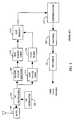
FIG. 1 .Data source 102 may be, for example, a variable rate vocoder such as that described inU.S. Patent No. 5,657,420 , entitled "Variable Rate Vocoder", issued August 8, 1997, assigned to the assignee of the present invention. Data source 102 generates traffic channel information in the form of frames of digital data. CRC andtail bit generator 104 calculates and appends cyclic redundancy check (CRC) bits and tail bits to the frames generated bydata source 102. The frame is then provided toencoder 106, which provides forward error correction coding, such as convolutional encoding, upon the frame as is known in the art. The encoded symbols are provided torepetition generator 120, which repeats the reordered symbols to provide the appropriate modulation symbol rate. The repeated symbols are then provided to interleaver108, which re-orders the symbols in accordance with a predetermined interleaver format. The repeated, interleaved symbol stream is then covered with one of a set of orthogonal Walsh sequences in traffic Walshcoverer 122, and gain adjusted ingain element 124. It should be understood that other forward link data formatters are also known in the art. For example, it is well known that therepetition generator 120 may be placed after theinterleaver 108.Pilot signal generator 128 generates a pilot signal, which may be a sequence of all ones. The pilot signal is then covered with the all-one Walsh sequence and combined with the output ofgain element 124 in combiner136. The combined pilot channel and traffic channel data (which may be plus or minus ones) is then spread inPN spreader 138 using a complex PN code generated byPN generator 140, and then transmitted byradio frequency transmitter 142 overantenna 144. A similar forward link data formatter is disclosed in co-pendingU.S. Patent Application Serial No. 08/886,604 , entitled "High Data Rate CDMA Wireless Communication System", assigned to the assignee of the present invention.- Other data formatting techniques also exist. For example, in the cdma2000 reverse link, the pilot signal is time-multiplexed with power control commands. Additionally, in W-CDMA, the forward link uses dedicated pilot signals that are time-multiplexed with other information.
FIG. 2 illustrates a functional block diagram of a typical prior art data demodulator for use in a CDMA mobile station.Receiver 202 receives and downconverts the signals transmitted bytransmitter 142 ofFIG. 1 . The digital baseband output ofreceiver 202 is despread inPN despreader 204 using the complex PN code generatedPN generator 206, which is the same complex PN code as that generated byPN generator 140 ofFIG. 1 .- The despread signal is then Walsh uncovered in traffic channel Walsh uncoverer208 using the same Walsh sequence as that of the traffic channel Walsh
coverer 122 ofFIG. 1 . The Walsh-uncovered chips are then accumulated into Walsh symbols in Walshchip summer 210 and provided as a traffic channel signal to dotproduct circuit 212. In some applications, an additional delay element (not shown) is introduced between Walshchip summer 210 and dotproduct circuit 212 to account for delays introduced bypilot filter 216. However, ifpilot filter 216 is a causal filter, such a delay element (not shown) is not necessary. The dot product circuit is also known as a "conjugate product" circuit. It performs the operation expressed mathematically by one of the following equivalent forms: <a,b>= a • b = ab*, where b* is the complex conjugate of b. - The despread signal is also provided to Walsh
chip summer 214 where they are accumulated into Walsh symbols and provided topilot filter 216 as pilot channel symbols. Note that since the pilot channel is covered with the all-one Walsh sequence in Walshcoverer 134 ofFIG. 1 , a vacuous operation, the corresponding uncoverer is also vacuous in operation. However, in the general case, the pilot signal may be uncovered using any same Walsh sequence as is used to cover it. Thepilot filter 216 serves to reject the noise in the pilot symbols, providing a phase and scale reference for thedot product circuit 212. - Once per symbol, the
dot product circuit 212 computes the component of the traffic channel signal in phase with the pilot channel signal generated by thepilot filter 216. As described inU.S. Patent No. 5,506,865 , entitled "Pilot Carrier Dot Product Circuit", issued April 9, 1996, assigned to the assignee of the present invention, the dot product adjusts both the received signal's phase and scale as needed for coherent demodulation. - The symbols output from
dot product circuit 212 are de-interleaved in de-interleaver218, using the same format used byinterleaver 108 ofFIG. 1 . The de-interleaved symbols are then decoded indecoder 220 according to the error correcting codes employed byencoder 106 ofFIG. 1 . The resulting decoded symbols are analyzed on a frame-by-frame basis byquality indicator 222 to ensure that the frame was properly decoded. If the frame was properly decoded, then that decoded frame is forwarded for further processing.Quality indicator 222 typically would examine the CRC portion of the frame, but may also use other frame quality indications such as Yamamoto metrics. - A
typical pilot filter 216 is implemented as an equal-weight finite impulse response (FIR) filter with all defining parameters (e.g., weighting, window width, window center) remaining constant regardless of the channel conditions. Alternately, an exponential decay infinite impulse response (IIR) filter having fixed parameters (e.g., decay time constant, scaling) may be used. In other words, the designer of a typical priorart pilot filter 216 will choose a static filter design that performs adequately for a given energy per bit to noise density ratio (Eb/N0) under most channel conditions of interest, but not optimally over the entire range of conditions. - As a mobile station (e.g., a cellular telephone, PCS telephone or other wireless remote communication terminal) moves through the terrestrial environment, the signals it transmits and receives will experience various types of fading. The mobile environment is usually characterized by fading that can be either Rician or Rayleigh in nature. Other types of fading are also possible. The fading characteristic in the typical channel signal is caused by the signal being reflected from many different features of the physical environment, thus it is called multipath fading. At the UHF frequency bands usually employed for mobile radio communications, including those of cellular mobile telephone systems, significant phase differences in signals traveling on different paths may occur. The possibility for both constructive and destructive summation of the signals may result, with on occasion deep fades occurring.
- Multipath channel fading is a function very sensitive to the physical position of the mobile unit. A small change in position of the mobile unit changes the physical delays of all the signal propagation paths, which further results in a different phase for each path. Thus, the motion of the mobile unit through the environment can result in a rapid fading process. For example, in the 850 MHz cellular radio frequency band, this fading can typically be as fast as one fade per second for every mile per hour of vehicle speed. Fading this severe can be extremely disruptive to signals in the terrestrial channel resulting in poor communication quality, particularly as the speed of the mobile station increases beyond 150 km/hr.
- As previously stated, the typical fixed-
parameter pilot filter 216 is not optimized for such a broad range of channel conditions. It is typically designed to work adequately at speeds from stationary to about 120 km/hr, or about as fast as a mobile station might be expected to travel in a motor vehicle on the highway. However, since the fading characteristics of the channel are vastly different as between a slow-moving mobile station and a fast-moving mobile station, the typical fixed-parameter pilot filter 216 can not be optimized for both extremes. Typically, this forces the designer to design apilot filter 216 that works well only when the mobile station is stationary or moves slower than about 150 km/hr, and works poorly beyond 150 km/hr. As transportation such as bullet trains and airplanes exceeds this speed, it is unlikely that the user of a mobile station will be able to obtain reliable communications. Even when operational, the signal to noise ratio (or in other words, the Eb/N0) of the communication link must be kept at a high enough level to be reliable in these severe fading conditions. Increasing the Eb/N0 of the communication link decreases the total capacity of the wireless system, particularly in a CDMA system where one transmitter's transmissions comprise interference to all other transmitters in the same CDMA frequency band. As a result, the designer of a fixed-parameter pilot filter 216 generally adopts an unfavorable compromise in selecting the filter parameters when faced with such a broad range of channel conditions. - Thus, there is a need for a more optimal pilot filtering method and apparatus, particularly in the wireless communication environment, that avoids these shortcomings in the prior art.
- The present invention is a novel and improved method and circuit for adaptively estimating channel conditions of a pilot channel in a wireless communication system. The method includes estimating channel statistics of the pilot channel, and adaptively filtering the pilot channel in response to the estimated channel statistics. The estimation is performed by filtering a channel signal derived from the pilot channel, or any channel bearing ambiguous data with the ambiguity removed after detection or decoding. This determines an estimated channel mean and an estimated channel covariance. In order to perform the adaptive filtering, the present invention partitions the pilot channel into one or more time slots and weights each time slot according to the estimated channel statistics. Thus, an advantage of the present invention is that it automatically and continually updates the pilot filter parameters in order to optimize the pilot filter performance over a broad range of channel conditions.
- In one embodiment of the present invention, the channel signal is filtered in one or more infinite impulse response (IIR) filters to determine the channel statistics. In a another embodiment, the channel signal is filtered in a combination of IIR and finite impulse response (FIR) filters to determine the channel statistics.
- In an embodiment applicable to the cdma2000 system wherein the pilot channel comprises a pilot signal portion having a known sign and a power control bit portion having an unknown sign. The method of the present invention may also include determining the sign of the power control bit portion, correcting the sign of the power control bit portion, and then combining the sign-corrected power control bit portion with the pilot signal portion to generate the channel signal from which the channel statistics are estimated by the channel statistics estimator. In yet another embodiment, the method includes determining the sign of the traffic signal and generating the channel signal in response to the traffic signal.
- In yet another embodiment applicable to a cdma2000 system, wherein the pilot channel comprises a sequence of power control groups, each power control group having a pilot signal portion having a known sign and a power control bit portion having an unknown sign, the time slots have a duration substantially equal to the duration of the pilot signal portion.
- A circuit for performing the method of the present invention is also described herein.
- The features, objects, and advantages of the present invention will become more apparent from the detailed description set forth below when taken in conjunction with the drawings in which like reference characters identify correspondingly throughout and wherein:
FIG. 1 is functional block diagram of a typical prior art forward link data formatter as used by a CDMA base station;FIG. 2 is a functional block diagram of a typical prior art demodulator for use in a CDMA mobile station;FIG. 3 is a first embodiment of the present invention illustrated as being implemented in a cdma2000 reverse link traffic channel demodulator; andFIG. 4 is a second embodiment of the present invention illustrated as being implemented in a cdma2000 forward link power control bit demodulator.- The present invention will now be described in an application that is specific but not limited to the demodulation of a cdma2000 reverse link signal. As is described in the proposed IS-2000 standard, the cdma2000 reverse link signal comprises a traffic channel signal and a reverse link pilot signal. Punctured into the reverse link pilot channel (R-PICH) is a forward link power control subchannel that is a single bit that spans the last quarter of each 1.25 ms power control group (PCG). This forward link power control bit is a signal from the mobile station to the base station transmitter to either increase or decrease its transmit power based on the mobile station's reception quality on the forward link. Such a reverse link pilot is described in detail in co-pending
U.S. Patent Application Serial No. 08/886,604 , entitled "HIGH DATA RATE CDMA WIRELESS COMMUNICATION SYSTEM", assigned to the assignee of the present invention. - Because the R-PICH is used by the base station as a coherent reference for data demodulation, a frequency reference for frequency tracking, and a received power reference for power control measurements, the uncertainty introduced by the forward link power control subchannel in the otherwise determinate signal could degrade the reverse link performance. In other words, the puncturing of the forward link power control subchannel into the R-PICH could lead to poorer the reverse link performance than a continuous pilot channel. For example, if we use only the non-punctured portion of the pilot channel to estimate the channel, the signal-to-noise ratio of the channel estimate calculated by the base station is decreased. A technique for resolving the sign ambiguity of the R-PICH and reconstructing a continuous pilot signal therefrom is given in copending
U.S. Patent Application Serial No. 09/298,394 - It will be understood by a person of ordinary skill in the art that although the present invention is disclosed with reference to a cdma2000 system having a R-PICH with a punctured power control subchannel, the present invention is equally applicable to other wireless communication systems having a non-punctured pilot channel. Thus, the following figures are intended to be example applications of the present invention and are not intended to limit the present invention to the cdma2000 system.
- Turning now to
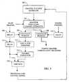
FIG. 3 , a first embodiment of the present invention is illustrated as being implemented in a cdma2000 reverse link traffic channel demodulator. Channelstatistic estimator 300 estimates channel statistics which are used by adaptivenon-causal channel estimator 302 to adaptively filter the pilot channel as will be discussed in more detail below. It should be noted that in other embodiments, indeed in the embodiment ofFIG. 4 described below, an adaptive causal channel estimator or filter may be used in place of adaptivenon-causal channel estimator 302. However, in the embodiment ofFIG. 3 , a non-causal filter is used for channel estimation due to its improved performance over a causal filter when the delay of the non-causal filter is tolerable. In the exemplary embodiment ofFIG. 3 , adaptivenon-causal channel estimator 302 is an FIR filter. However, in the general case, adaptivenon-causal channel estimator 302 may be an IIR filter or a hybrid filter with both FIR and IIR characteristics. One simple example is a filter that outputs the difference of two exponential decay IIR filters of the same time constant but different weights, such that the effective impulse response of the filter is of finite extent. Another example would be a cascaded FIR and IIR filter. - The filtered pilot channel symbols are then input to conjugate
product circuits Conjugate product circuit 308 also receives as a second input, the despread, Walsh uncovered, and delayed traffic channel that has been delayed bydelay circuit 310.Delay circuit 310 delays the traffic channel by an amount substantially equal to the delay introduced by adaptivenon-causal channel estimator 302.Conjugate product circuit 308 produces traffic channel symbols (soft decisions) for further de-interleaving and decoding as is known in the art. Conjugate product circuit 306 receives as a second input the delayed pilot channel that has been delayed bydelay circuit 304.Delay circuit 304 delays the pilot channel by an amount substantially equal to the delay introduced by adaptivenon-causal channel estimator 302.Conjugate product circuit 306 performs a conjugate multiplication of theestimator 302 output with the delayed pilot channel which contains a power control bit punctured into the reverse link pilot channel. Conjugate product circuit then forwards the resultant power control bit signal to past forward link (FL) power control bit (PCB)detector 314.- Past
FL PCB detector 314 compares the resultant power control bit signal to a threshold and thereby determines the sign of the punctured FL PCB. It should be noted that the term "past" is used in describing the operation performed by pastFL PCB detector 314 because the power control bit being detected at any given time is the power control bit from a past power control group, as delayed bydelay 304 and adaptivenon-causal channel estimator 302. The FL PCB decision determined by pastFL PCB detector 314 is then forwarded toPCB sign corrector 316 where the sign of the PCB is flipped, if necessary, to match the sign of the remainder of the pilot channel (+1). The output ofPCB sign corrector 316 is then provided, along with the further delayed pilot channel fromdelay 312, to time multiplexer (MUX)318.Time MUX 318 provides, during the first ¾ of the power control group, an output equal to the further delayed pilot channel fromdelay 312, which compensates for the processing time of the pastFL PCB detector 314.Time MUX 318 provides, during the remaining ¼ of the power control group, the output ofPCB sign corrector 316 which is now equal in sign (+1) to the pilot channel. The resulting output signal fromtime MUX 318, is, therefore, a reconstructed pilot channel signal of constant sign. A similar technique for continuous pilot channel reconstruction in given in the above-incorporated co-pending application serial 09/298,394. - The reconstructed channel signal is provided to channel
statistic estimator 300 which estimates channel statistics therefrom for use in setting the weighting factors used by adaptivenon-causal channel estimator 302 as mentioned above. The generation of channel statistics by channelstatistic estimator 300 and the application of weighting factors by adaptivenon-causal channel estimator 302 will be discussed in further detail below. - It should be noted that the elements in the left-hand side of
FIG. 3 that are involved solely in generating the reconstructed channel signal for use by channel statistic estimator300 (i.e.,delay 304,conjugate product circuit 306,delay 312, pastFL PCB detector 314,PCB sign corrector 316 and time MUX 318) are necessary only for a punctured pilot channel such as the R-PICH of the cdma2000 reverse link. These elements may be omitted in applications having a non-punctured or otherwise continuous pilot channel. In such a case, the pilot channel signal itself may be sufficient for use by channelstatistic estimator 300. Furthermore, the channel signal may also be generated from the additional energy contained in the traffic signal using the method described in co-pendingU.S. Patent Application Serial No. 09/289,073 FIG. 3 , would be the reconstructed channel signal output fromtime MUX 318. Thus, in the general case, the generation of the channel signal, i.e., a signal that represents the channel, may be a weighted combination of contributions from the pilot portion of the R-PICH, the sign-corrected FL PCB from the R-PICH, and the sign-corrected traffic from one or more traffic channels. - Turning now to
FIG. 4 , a second embodiment of the present invention is illustrated as being implemented in a forward link power control bit demodulator. InFIG. 4 , channelstatistic estimator 400, which may be the same as channelstatistic estimator 300 ofFIG. 3 , is illustrated as receiving the channel signal, which may be the reconstructed channel signal ofFIG. 3 in the case of the R-PICH demodulator ofFIG. 3 , or a reconstructed channel signal from a sign-corrected traffic channel after successful decoding, re-encoding, and re-interleaving as detailed in the above-referencedU.S. Patent Application Serial No. 09/289,073 , or a weighted combination of the two signals. In the general case,channel statistics estimator 400 may be different thanchannel statistics estimator 300. Both may use essentially the same algorithm, described in detail below, but they may operate on different data, or over different time slots, or even different channel signal inputs. The channel signal is operated on by channelstatistic estimator 400 as will be described further below in order to estimate the channel statistics by which adaptive predictivecausal channel estimator 402 will assign filter weighting coefficients. In the exemplary embodiment ofFIG. 4 , adaptive predictivecausal channel estimator 402 is an FIR filter. However, in the general case, it may be an IIR filter, or a hybrid filter having both FIR and IIR characteristics. - Adaptive predictive
causal channel estimator 402 provides a channel estimate throughdelay 404 toconjugate product circuit 406.Conjugate product circuit 406 performs a conjugate multiplication on the channel estimate and the pilot channel (in this case, the R-PICH) to demodulate the FL PCB punctured into the R-PICH. The resultant power control bit signal is then forwarded to currentFL PCB detector 408 for determination of the sign of the current FL PCB. CurrentFL PCB detector 408 may be of similar construction to pastFL PCB detector 314 ofFIG. 3 . CurrentFL PCB detector 408 estimates a current FL PCB decision regarding the sign of the FL PCB by comparing the power control bit signal fromconjugate product circuit 406 to a threshold. The current FL PCB decision may then be used by the forward link transmitter (not shown) to increase or decrease its power as necessary. - As described above, in both the embodiments of
FIG. 3 andFIG. 4 , the channelstatistic estimators non-causal channel estimator 302 and adaptive predictivecausal channel estimator 402, respectively, in setting their respective filter coefficients. To explain how this process occurs, the following mathematical description will be introduced. First, consider the received channel signal of a particular Rake finger of a Rake receiver entering the mobile station channelstatistic estimator 
where
y[n] is a column vector representing the actual received channel signal at time slot n;
a[n] is a column vector representing the actual information signal as a true representation of the channel at time slot n;
w[n] is a column vector representing the actual noise contained in the channel signal at time slot n; and
n is a vector index in the time domain, and therefore may represent an arbitrary time slot for sampling the received channel signal. - Therefore, the dimension of the column vectors a[n], w[n], y[n], or the number of integral values that n can take on, is the same as the number of time slots of received channel signal used as input for adaptive channel estimation. In the second exemplary embodiment applicable to the predictive estimation of a FL PCB in a cdma2000 R-PICH, each time slot may be ¾ of a single 1.25ms power control group (i.e., the non-punctured portion of the pilot channel). Thus, if we use 2 PCG worth of channel signal as input for estimation, as n ranges from 1 and 2, y[1] represents the received channel signal of the current ¾ PCG of pilot whereas y[2] represents the received channel signal of the previous _ PCG of pilot. These y[1] and y[2] values can be obtained by simple averaging of pilot symbols over the said ¾ PCG of pilots.
- Other embodiments may use larger or smaller time slots depending on the resolution and estimation accuracy desired as a tradeoff to the costs of computation. For example, in the cdma2000 embodiment, the punctured FL PCB may be one coherent time slot, with an ambiguous sign, or it can comprise several smaller coherent time slots if finer resolution is desired. In the general case, the time slots may be of unequal duration, though the received channel signal at each time slot could be weighted appropriately to normalize the information signal amplitude or, depending on the application, the signal-to-noise ratio. In other embodiments, the time slots may be a configurable parameter. If a partition of the channel signal into finer time slots is used, the index n can range from one to a higher number. If a non-causal estimator is desired, as in the embodiment of
FIG. 3 , some of the elements of the column vectors y[n], a[n], and w[n] may also represent values after the time of interest in the system where the channel estimate is desired. - We must estimate the actual channel value x at a given moment, as shown below in Equation (2). Equation (2) represents the operation performed by both adaptive
non-causal channel estimator 302 and adaptive predictivecausal channel estimator 402. One difference between the two applications are the different partitions of the channel signal into different time slots as discussed above. Note that all estimates herein are denoted by the ^ ("hat") notation Let x be the desired channel value at a time slot of interest. For example, while the index n for the y, a, and w vectors takes on the values 1 and 2 representing the pilot portions of the pilot channel during the current and previous PCGs as in the exemplary embodiment ofFIG. 4 , x represents the channel value at the current PCB portion of the pilot channel,
where
x̂ is the estimated channel value at the time slot corresponding to the PCB portion of the pilot channel,
m̂x is the estimated mean of x;
m̂y[n] is the estimated mean of the channel signal at time slot n; and
H is a filter vector described byH =K̂xy(K̂yy)-1
where: - K̂xy is the estimated covariance matrix of the x and y[n]; and
- K̂yy is the estimated covariance matrix of the vector y[n], and the superscript -1 represents the matrix inversion operation.
- In other words, H is a vector representation of a linear filter that when the filter is applied to an arbitrary signal z[n], the output resulting from the operation can be described in the following in time domain notation:

where k is the vector index. - It is also possible to make x into a vector by packing more values into it when the channel estimate at multiple time instances are desired, especially if this provides extra implementational convenience in some embodiment of application due to the computational architecture used. Thus:


- The valuesm̂y[n],K̂xy, andK̂yy are what are referred to herein as the estimated channel statistics. These are the values estimated by
channel statistics estimator non-causal channel estimator 302 and adaptive predictivecausal channel estimator 402, respectively, in determining the filter weighting used to estimatex̂. Thus, these channel statistics are the needed components of Equation (2) above, given that y[n], the actual received channel signal, is already known. - Next, the generation of these channel statistics is described. Channel
statistic estimators 
- Note that y[n] now represents a signal vector in time, and the time index over which the convolution operation is applied is not shown. If it were shown, bothm̂y[n] and y[n] would have two indices, with the first one (shown) representing the time slots (e.g. "current PCG" and "previous PCG" as used for the second exemplary embodiment of the application above), and the second (not shown) representing the updating of the vector values as what is "current time" proceeds.
- The same method is used to calculate the estimatem̂x[n] since the elements ofm̂x[n] represent the estimated channel just as the elements ofm̂y[n] do, though at perhaps different time slots, so that only a shuffling of time slot indices is required before the direct application of the same method. Note that the channel mean usually does not change often, and when the time slots used as estimation inputs are close together in time, we may use one single value to represent all the elements inm̂x[n],m̂y[n] because they are similar in value, thus possibly saving computation. In another embodiment of application of the present invention in which the channel is known to have zero-mean,m̂x[n],m̂y[n] can be taken to be zero, thus simplifying Equation (2).

- Channel
statistic estimators 
where
g2 is a filter impulse response, which in the general case may be either an FIR or an IIR or hybrid filter that has both FIR and IIR characteristics;
m and n are the row and column vector indices, respectively; and
y*[n] is the conjugate of y[n].
Again, the time index over which the convolution operation is applied is not shown. - Channel
statistic estimators 
where
g3 is a filter impulse response, which in the general case may be either an FIR or an IIR or hybrid filter that has both FIR and IIR characteristics; and
y*[m] is the conjugate of y[m].
Again, the time index over which the convolution operation is applied is not shown. The present invention also contemplates taking advantage of the fact thatK̂yy may be conjugate symmetric, that is,
- In addition, if part of the received channel signal vector y[n] has time slots of equal durations representing values equally spaced in time, we may also take advantage of the shift-invariant property of the covariance function and saves computation further,

- The time constants of these three filters, g1, g2, g3, are usually picked for the particular application at hand depending on the system parameters. For example, if the channel statistics do not change over a duration of time on the order of one second, the time constants of the filters g1, g2, g3, may be chosen to be one second or shorter.
- When multiple Rake fingers are used, a more sophisticated application of the present invention can make sure that the channel statistics from the different fingers are the same or similar, and use all the channel signals y[n] from different fingers for the statistics estimation, giving more accurate estimates due to the increased amount of available input for estimating the same or similar values of channel statistics.
- So, as can be seen from the above mathematical relationships, channel
statistic estimators non-causal channel estimator 302 and adaptive predictivecausal channel estimator 402, which may also be referred to generically as "pilot filters"). The channel estimators ofFIG. 3 andFIG. 4 then use these channel statistics in carrying out the operation described by Equation (2) above, i.e., adaptively estimating the channel conditions. - Central to the present invention is the concept that the channel statistics are slowly but constantly changing as the mobile station moves through the fading environment. These channel statistics are continually updated by channel
statistic estimators non-causal channel estimator 302 and adaptive predictivecausal channel estimator 402, respectively. Because these channel statistics form the basis for Equation (2), the adaptive filtering operation, both adaptivenon-causal channel estimator 302 and adaptive predictivecausal channel estimator 402 are changing their filter parameters in response to changes in channel conditions. - Advantageous to the present invention, Equation (2) gives an estimator that minimizes the mean squared error of the estimate output. Moreover, the present invention provides convenient and efficient methods to automatically calculate all the ingredients for employing this equation. Thus, both adaptive
non-causal channel estimator 302 and adaptive predictivecausal channel estimator 402 are continually updated by channelstatistic estimators non-causal channel estimator 302 and adaptive predictivecausal channel estimator 402 to generate the best channel estimate for a given channel condition under a broad range of channel conditions. In sharp contrast to the prior art, the present invention provides a method and apparatus for adaptively estimating the channel conditions in a wireless communication system based on the use of estimated channel statistics to determine the channel estimator's filter parameters. Thus, the present invention is always optimized for the current channel conditions, resulting in a significantly lower communication link Eb/N0 requirement for a given bit error rate. - The previous description of the preferred embodiments is provided to enable any person skilled in the art to make or use the present invention. The various modifications to these embodiments will be readily apparent to those skilled in the art, and the generic principles defined herein may be applied to other embodiments without the use of the inventive faculty. Thus, the present invention is not intended to be limited to the embodiments shown herein but is to be accorded the widest scope consistent with claims.


Claims (17)
- A method for adaptively estimating channel conditions of a pilot channel in a wireless communication system, the method comprising the steps of:estimating channel statistics of said pilot channel; andadaptively filtering said pilot channel in response to said estimated channel statistics;wherein said estimating step further comprises filtering a channel signal derived from said pilot channel to determine an estimated channel mean and an estimated channel covariance.
- The method of claim 1 wherein said step of adaptively filtering said pilot channel comprises the steps of:partitioning said pilot channel into one or more time slots; andweighting each time slot according to said estimated channel statistics.
- The method of claim 2 wherein said step of filtering said channel signal comprises filtering said channel signal in an infinite impulse response filter.
- The method of claim 2 wherein said step of filtering said channel signal comprises filtering said channel signal in a combination of infinite impulse response and finite impulse response filters.
- The method of claim 2 wherein said pilot channel comprises a pilot signal portion having a known sign and a power control bit portion having an unknown sign, the method further comprising the steps of:determining said sign of said power control bit portion;correcting said sign of said power control bit portion;combining said sign-corrected power control bit portion with said pilot signal portion to generate said channel signal.
- The method of claim 2 wherein said wireless communication system further comprises a traffic channel, said traffic channel having a traffic signal of unknown signs the method further comprising the steps of:determining said signs of said traffic signal;generating said channel signal in response to said traffic signal.
- The method of claim 2 wherein said pilot channel comprises a sequence of power control groups, each power control group having a pilot signal portion having a known sign and a power control bit portion having an unknown sign, and wherein said time slot has a duration substantially equal to the duration of said pilot signal portion.
- A circuit for adaptively estimating channel conditions of a pilot channel in a wireless communication system, the circuit comprising:a channel statistics estimator (300, 400) that estimates channel statistics of said pilot channel; andan adaptive pilot filter (302, 402) that adaptively filters said pilot channel in response to said estimated channel statistics;wherein said channel statistics estimator (300, 400) filters a channel signal derived from said pilot channel to determine an estimated channel mean and an estimated channel covariance.
- The circuit of claim 8 wherein said channel statistics estimator (300, 400) comprises means for partitioning said pilot channel into one or more time slots and wherein said comprises means for weighting adaptive pilot filter each time slot according to said channel statistics.
- The circuit of claim 9 wherein said channel statistics estimator (300, 400) comprises an infinite impulse response filter for filtering said channel signal.
- The circuit of claim 9 wherein said channel statistics estimator (300, 400) comprises a combination of infinite impulse response and finite impulse response filters for filtering said channel signal.
- The circuit of claim 9 wherein said pilot channel comprises a pilot signal portion having a known sign and a power control bit portion having an unknown sign, the circuit further comprising:a power control bit sign detector (314) for determining said sign of said power control bit portion;a power control bit sign corrector (316) for correcting said sign of said power control bit portion;a multiplexer (318) for combining said sign-corrected power control bit portion with said pilot signal portion to generate said channel signal.
- The circuit of claim 9 wherein said pilot channel comprises a sequence of power control groups, each power control group having a pilot signal portion having a known sign and a power control bit portion having an unknown sign, and wherein said time slot has a duration substantially equal to the duration of said pilot signal portion.
- The method of claim 1 wherein said step of filtering a channel signal further comprises the steps of:weighting the pilot channel signal with a first weighting factor to obtain a first weighted received pilot channel signal;weighting a second received pilot channel signal with a second weighting factor to obtain a second weighted received pilot channel signal; andcombining said first and second weighted received pilot channel signals to generate said channel signal.
- The method of claim 1 wherein said step of estimating further comprises combining a plurality of channel signals from a plurality of rake receiver fingers.
- The circuit of claim 8 wherein said channel statistics estimator further comprises: means for weighting said pilot channel signal with a first weighting factor thus obtaining a first weighted received pilot channel signal; means for weighting a second received pilot channel signal with a second weighting factor thus obtaining a second weighted received pilot channel signal, and means for combining said first and second weighted received pilot channel signals to generate said channel signal.
- The circuit of claim 8 wherein said channel statistics estimator (300, 400) further comprises means for combining a plurality of channel signals from a plurality of rake receiver fingers.
Applications Claiming Priority (3)
| Application Number | Priority Date | Filing Date | Title |
|---|---|---|---|
| US379809 | 1999-08-23 | ||
| US09/379,809US6493329B1 (en) | 1999-08-23 | 1999-08-23 | Adaptive channel estimation in a wireless communication system |
| PCT/US2000/022731WO2001015332A1 (en) | 1999-08-23 | 2000-08-16 | Adaptive channel estimation in a wireless communication system |
Publications (2)
| Publication Number | Publication Date |
|---|---|
| EP1206843A1 EP1206843A1 (en) | 2002-05-22 |
| EP1206843B1true EP1206843B1 (en) | 2008-10-22 |
Family
ID=23498784
Family Applications (1)
| Application Number | Title | Priority Date | Filing Date |
|---|---|---|---|
| EP00954139AExpired - LifetimeEP1206843B1 (en) | 1999-08-23 | 2000-08-16 | Adaptive channel estimation in a wireless communication system |
Country Status (12)
| Country | Link |
|---|---|
| US (2) | US6493329B1 (en) |
| EP (1) | EP1206843B1 (en) |
| JP (1) | JP4870301B2 (en) |
| KR (2) | KR100806091B1 (en) |
| CN (2) | CN1377530A (en) |
| AT (1) | ATE412274T1 (en) |
| AU (1) | AU6647400A (en) |
| BR (1) | BR0013506A (en) |
| DE (1) | DE60040604D1 (en) |
| HK (1) | HK1048207A1 (en) |
| TW (1) | TW497340B (en) |
| WO (1) | WO2001015332A1 (en) |
Cited By (1)
| Publication number | Priority date | Publication date | Assignee | Title |
|---|---|---|---|---|
| JP2003513484A (en)* | 1999-08-23 | 2003-04-08 | クゥアルコム・インコーポレイテッド | Adaptive channel estimation in wireless communication systems |
Families Citing this family (72)
| Publication number | Priority date | Publication date | Assignee | Title |
|---|---|---|---|---|
| US6414988B1 (en)* | 1999-05-12 | 2002-07-02 | Qualcomm Incorporated | Amplitude and phase estimation method in a wireless communication system |
| US6967998B1 (en)* | 1999-11-12 | 2005-11-22 | Qualcomm Incorporated | Method and apparatus for monitoring transmission quality |
| US6810264B1 (en)* | 1999-11-16 | 2004-10-26 | Samsung Electronics Co., Ltd. | Power controlling apparatus and method in mobile communication system |
| WO2001067665A2 (en)* | 2000-03-09 | 2001-09-13 | Raytheon Company | Frequency domain direct sequence spread spectrum with flexible time frequency code |
| US20090262700A1 (en)* | 2000-03-09 | 2009-10-22 | Franceschini Michael R | Frequency domain direct sequence spread spectrum with flexible time frequency code |
| JP3805205B2 (en)* | 2000-04-06 | 2006-08-02 | 株式会社エヌ・ティ・ティ・ドコモ | Method and apparatus for measuring communication quality in CDMA cellular system |
| FI20001513A7 (en) | 2000-06-26 | 2001-12-27 | Nokia Corp | Method for improving the quality of data transmission |
| KR100377969B1 (en)* | 2000-07-10 | 2003-03-29 | 이용환 | Apparatus for Direct Sequence Spread Spectrum Receiver using Adaptive Channel Estimator |
| US6647055B2 (en)* | 2000-08-31 | 2003-11-11 | Wen-Yi Kuo | Adaptive channel estimation using continuous pilot signal based on doppler period |
| GB2370469B (en)* | 2000-09-07 | 2004-10-27 | Nec Corp | Improvements in CDMA receivers |
| US6980781B2 (en)* | 2001-02-14 | 2005-12-27 | Denso Corporation | Dynamic second stage filtering for pilot energy strength measurements |
| WO2002078183A1 (en)* | 2001-03-26 | 2002-10-03 | Japan Science And Technology Corporation | Filter apparatus, reception apparatus, transmission apparatus, diffusion modulation apparatus, pseudo-random number sequence output apparatus, filter method, reception method, transmission method, diffusion modulation method, pseudo-random number sequence output method, and program |
| US20040185786A1 (en)* | 2001-04-25 | 2004-09-23 | Ramin Mirbaha | Quality of service state predictor for and advanced mobile devices |
| WO2002096049A1 (en)* | 2001-05-23 | 2002-11-28 | Nortel Networks Limited | Channel estimation in cdma communications systems using both lower power pilot channel and higher power date channel |
| US7230975B2 (en) | 2001-08-07 | 2007-06-12 | Qualcomm Incorporated | Adaptive pilot filter for a wireless communication system |
| US7236514B2 (en)* | 2001-10-01 | 2007-06-26 | Ericsson, Inc. | Communications methods, apparatus and computer program products using gain multipliers |
| KR100849333B1 (en)* | 2001-10-12 | 2008-07-29 | 삼성전자주식회사 | Channel estimator apparatus and method |
| US7206342B1 (en)* | 2001-12-07 | 2007-04-17 | Applied Micro Circuits Corp. | Modified gain non-causal channel equalization using feed-forward and feedback compensation |
| US7139325B1 (en)* | 2001-12-07 | 2006-11-21 | Applied Micro Circuits Corporation | System and method for five-level non-causal channel equalization |
| US6961390B1 (en)* | 2001-12-07 | 2005-11-01 | Applied Micro Circuits Corporation | Systems and methods for non-casual channel equalization in an asymmetrical noise environment |
| US20030227881A1 (en)* | 2002-02-19 | 2003-12-11 | Liangchi Hsu | Apparatus, and associated method, for facilitating delivery of signaling data in a packet radio communication system |
| US6760362B2 (en)* | 2002-03-15 | 2004-07-06 | Qualcomm Incorporated | Dynamic pilot filter bandwidth estimation |
| US7295808B2 (en) | 2002-09-05 | 2007-11-13 | Soliman Samir S | Method of and system for calibrating a repeater |
| US7454209B2 (en)* | 2002-09-05 | 2008-11-18 | Qualcomm Incorporated | Adapting operation of a communication filter based on mobile unit velocity |
| SG107112A1 (en)* | 2002-09-06 | 2004-11-29 | Oki Techno Ct Singapore Pte | A method of estimating fading in a pilot channel |
| US20040062217A1 (en)* | 2002-09-30 | 2004-04-01 | Farrokh Abrishamkar | Method and apparatus for pilot estimation using an adaptive prediction error method with a kalman filter and a gauss-newton algorithm |
| US7042928B2 (en)* | 2002-10-23 | 2006-05-09 | Qualcomm Incorporated | Method and apparatus for pilot estimation using prediction error method |
| DE10250361B4 (en) | 2002-10-29 | 2009-12-24 | Infineon Technologies Ag | Apparatus and method for processing pilot symbols for channel estimation by means of adaptive low-pass filtering |
| SG108906A1 (en)* | 2003-02-27 | 2005-02-28 | Sony Corp | Digital communications channel estimation method |
| US7428262B2 (en)* | 2003-08-13 | 2008-09-23 | Motorola, Inc. | Channel estimation in a rake receiver of a CDMA communication system |
| EP1513270B1 (en)* | 2003-09-05 | 2010-11-10 | STMicroelectronics Srl | Method for estimating the Doppler spread in radio mobile telecommunication systems |
| KR100566210B1 (en)* | 2003-09-22 | 2006-03-29 | 삼성전자주식회사 | Device and Method for Allocating Channel in Wireless Communication System |
| KR100620914B1 (en)* | 2004-04-07 | 2006-09-13 | 삼성전자주식회사 | Apparatus and method for switching between MC mode and diversity mode in broadband wireless communication system |
| US20050227697A1 (en)* | 2004-04-12 | 2005-10-13 | Lucent Technologies, Inc. | Method and apparatus for channel prediction in wireless networks |
| US6968832B1 (en)* | 2004-05-06 | 2005-11-29 | International Engine Intellectual Property Company, Llc | Connection system for exhaust gas recirculation (EGR) |
| JP2005328312A (en)* | 2004-05-13 | 2005-11-24 | Ntt Docomo Inc | Channel estimation device, channel estimation method, and radio receiver |
| TWI279998B (en)* | 2004-05-25 | 2007-04-21 | Realtek Semiconductor Corp | Adaptive channel estimation method for multi-carrier communication system |
| US20060128326A1 (en)* | 2004-12-09 | 2006-06-15 | Interdigital Technology Corporation | Low complexity adaptive channel estimation |
| US7573964B2 (en)* | 2004-12-16 | 2009-08-11 | Motorola, Inc. | Channel estimator with extended channel bandwidth |
| WO2006099540A2 (en) | 2005-03-15 | 2006-09-21 | Trapeze Networks, Inc. | System and method for distributing keys in a wireless network |
| CN1870475B (en)* | 2005-05-23 | 2010-04-21 | 大唐移动通信设备有限公司 | Channel measurement method based on laterally spaced adaptive filter |
| CN1960556B (en)* | 2005-09-20 | 2012-01-11 | 开曼群岛威睿电通股份有限公司 | Iterative channel prediction |
| US7573859B2 (en)* | 2005-10-13 | 2009-08-11 | Trapeze Networks, Inc. | System and method for remote monitoring in a wireless network |
| US7724703B2 (en)* | 2005-10-13 | 2010-05-25 | Belden, Inc. | System and method for wireless network monitoring |
| US7551619B2 (en)* | 2005-10-13 | 2009-06-23 | Trapeze Networks, Inc. | Identity-based networking |
| WO2007044986A2 (en) | 2005-10-13 | 2007-04-19 | Trapeze Networks, Inc. | System and method for remote monitoring in a wireless network |
| US8638762B2 (en)* | 2005-10-13 | 2014-01-28 | Trapeze Networks, Inc. | System and method for network integrity |
| KR100728257B1 (en)* | 2005-10-27 | 2007-06-13 | 한국전자통신연구원 | Decision Feedback Equalizer and its Method Using Channel Characteristics Changes |
| US7558266B2 (en) | 2006-05-03 | 2009-07-07 | Trapeze Networks, Inc. | System and method for restricting network access using forwarding databases |
| US8966018B2 (en)* | 2006-05-19 | 2015-02-24 | Trapeze Networks, Inc. | Automated network device configuration and network deployment |
| US9191799B2 (en) | 2006-06-09 | 2015-11-17 | Juniper Networks, Inc. | Sharing data between wireless switches system and method |
| US8818322B2 (en) | 2006-06-09 | 2014-08-26 | Trapeze Networks, Inc. | Untethered access point mesh system and method |
| US9258702B2 (en) | 2006-06-09 | 2016-02-09 | Trapeze Networks, Inc. | AP-local dynamic switching |
| US8340110B2 (en)* | 2006-09-15 | 2012-12-25 | Trapeze Networks, Inc. | Quality of service provisioning for wireless networks |
| US7873061B2 (en) | 2006-12-28 | 2011-01-18 | Trapeze Networks, Inc. | System and method for aggregation and queuing in a wireless network |
| US20080226075A1 (en)* | 2007-03-14 | 2008-09-18 | Trapeze Networks, Inc. | Restricted services for wireless stations |
| US20080276303A1 (en)* | 2007-05-03 | 2008-11-06 | Trapeze Networks, Inc. | Network Type Advertising |
| US8902904B2 (en)* | 2007-09-07 | 2014-12-02 | Trapeze Networks, Inc. | Network assignment based on priority |
| US8238942B2 (en)* | 2007-11-21 | 2012-08-07 | Trapeze Networks, Inc. | Wireless station location detection |
| US8150357B2 (en)* | 2008-03-28 | 2012-04-03 | Trapeze Networks, Inc. | Smoothing filter for irregular update intervals |
| US8978105B2 (en) | 2008-07-25 | 2015-03-10 | Trapeze Networks, Inc. | Affirming network relationships and resource access via related networks |
| US8238298B2 (en)* | 2008-08-29 | 2012-08-07 | Trapeze Networks, Inc. | Picking an optimal channel for an access point in a wireless network |
| US9270423B2 (en)* | 2008-10-22 | 2016-02-23 | Zte (Usa) Inc. | Reverse link acknowledgment signaling |
| US9713067B2 (en) | 2009-05-08 | 2017-07-18 | Zte (Usa) Inc. | Reverse link signaling techniques for wireless communication systems |
| US9049065B2 (en)* | 2009-05-11 | 2015-06-02 | Qualcomm Incorporated | Removal of ICI/ISI errors in frequency domain channel estimation for wireless repeaters |
| US20110116531A1 (en)* | 2009-05-11 | 2011-05-19 | Qualcomm Incorporated | Removal of multiplicative errors in frequency domain channel estimation for wireless repeaters |
| US20100284447A1 (en)* | 2009-05-11 | 2010-11-11 | Qualcomm Incorporated | Frequency domain feedback channel estimation for an interference cancellation repeater including sampling of non causal taps |
| JP5645928B2 (en)* | 2009-06-19 | 2014-12-24 | コーダ ワイヤレス ピーティーワイ リミテッドCohda Wireless Pty Ltd | Environmental evaluation in wireless communication systems |
| CN103095358B (en)* | 2011-11-02 | 2016-08-03 | 华为技术有限公司 | The detection method of a kind of multiple-input, multiple-output signal and device |
| US9401823B2 (en)* | 2013-11-26 | 2016-07-26 | Plusn Llc | System and method for radio frequency carrier aggregation |
| CN109302360B (en)* | 2017-07-24 | 2022-02-01 | 北京紫光展锐通信技术有限公司 | Channel estimation method and device, computer readable storage medium and terminal |
| CN115250125B (en)* | 2022-07-11 | 2024-02-27 | 北京跟踪与通信技术研究所 | RAKE receiver and improved receiving method for satellite communication system |
Family Cites Families (22)
| Publication number | Priority date | Publication date | Assignee | Title |
|---|---|---|---|---|
| US4901307A (en) | 1986-10-17 | 1990-02-13 | Qualcomm, Inc. | Spread spectrum multiple access communication system using satellite or terrestrial repeaters |
| NO163120C (en)* | 1987-05-19 | 1990-04-04 | Sintef | PROCEDURE FOR DEMODULATION IN DIGITAL COMMUNICATION SYSTEMS WITH MULTIPLE PROPAGATION. |
| US5119196A (en)* | 1990-06-25 | 1992-06-02 | At&T Bell Laboratories | Ghost cancellation of analog tv signals |
| US5103459B1 (en) | 1990-06-25 | 1999-07-06 | Qualcomm Inc | System and method for generating signal waveforms in a cdma cellular telephone system |
| CA2568984C (en) | 1991-06-11 | 2007-07-10 | Qualcomm Incorporated | Variable rate vocoder |
| ZA938324B (en) | 1992-11-24 | 1994-06-07 | Qualcomm Inc | Pilot carrier dot product circuit |
| US5357574A (en)* | 1992-12-14 | 1994-10-18 | Ford Motor Company | Coherent signal generation in digital radio receiver |
| JPH08116303A (en)* | 1994-10-18 | 1996-05-07 | Toshiba Corp | Spread spectrum wireless communication system, wireless communication device for base station and wireless communication device for mobile station used in this system |
| US6101399A (en)* | 1995-02-22 | 2000-08-08 | The Board Of Trustees Of The Leland Stanford Jr. University | Adaptive beam forming for transmitter operation in a wireless communication system |
| US5764687A (en) | 1995-06-20 | 1998-06-09 | Qualcomm Incorporated | Mobile demodulator architecture for a spread spectrum multiple access communication system |
| US5687198A (en)* | 1996-01-04 | 1997-11-11 | Motorola, Inc. | Channel estimation in a communication system |
| US5698984A (en)* | 1996-01-30 | 1997-12-16 | Fluke Corporation | Adaptive digital filter for improved measurement accuracy in an electronic instrument |
| US5737327A (en)* | 1996-03-29 | 1998-04-07 | Motorola, Inc. | Method and apparatus for demodulation and power control bit detection in a spread spectrum communication system |
| US5799011A (en)* | 1996-03-29 | 1998-08-25 | Motorola, Inc. | CDMA power control channel estimation using dynamic coefficient scaling |
| US6151484A (en)* | 1997-08-08 | 2000-11-21 | Ericsson Inc. | Communications apparatus and methods for adaptive signal processing based on mobility characteristics |
| KR100224864B1 (en)* | 1997-08-20 | 1999-10-15 | 윤종용 | Equalization Methods and Equalizers for OFDM Receivers |
| EP0899896A1 (en)* | 1997-08-27 | 1999-03-03 | Siemens Aktiengesellschaft | Method and system to estimate spatial parameters of transmission channels |
| JP3441636B2 (en)* | 1997-11-21 | 2003-09-02 | 株式会社エヌ・ティ・ティ・ドコモ | Apparatus and method for determining channel estimation value, receiving apparatus, and transmission system |
| JP3411231B2 (en)* | 1999-02-12 | 2003-05-26 | 沖電気工業株式会社 | Channel estimation circuit |
| US6219344B1 (en)* | 1999-04-21 | 2001-04-17 | Infineon Technologies Ag | Pilot aided traffic channel estimation for CDMA cellular systems |
| US6493329B1 (en)* | 1999-08-23 | 2002-12-10 | Qualcomm Incorporated | Adaptive channel estimation in a wireless communication system |
| JP3562502B2 (en)* | 2001-09-27 | 2004-09-08 | 日本電気株式会社 | CDMA receiver and channel estimation method for the same |
- 1999
- 1999-08-23USUS09/379,809patent/US6493329B1/ennot_activeExpired - Lifetime
- 2000
- 2000-08-16ATAT00954139Tpatent/ATE412274T1/ennot_activeIP Right Cessation
- 2000-08-16BRBR0013506-2Apatent/BR0013506A/ennot_activeIP Right Cessation
- 2000-08-16JPJP2001518942Apatent/JP4870301B2/ennot_activeExpired - Lifetime
- 2000-08-16AUAU66474/00Apatent/AU6647400A/ennot_activeAbandoned
- 2000-08-16WOPCT/US2000/022731patent/WO2001015332A1/enactiveApplication Filing
- 2000-08-16DEDE60040604Tpatent/DE60040604D1/ennot_activeExpired - Lifetime
- 2000-08-16KRKR1020077010665Apatent/KR100806091B1/ennot_activeExpired - Fee Related
- 2000-08-16CNCN00811909Apatent/CN1377530A/enactivePending
- 2000-08-16KRKR1020027002316Apatent/KR100795738B1/ennot_activeExpired - Lifetime
- 2000-08-16HKHK03100199.6Apatent/HK1048207A1/enunknown
- 2000-08-16CNCN2007101387083Apatent/CN101119130B/ennot_activeExpired - Lifetime
- 2000-08-16EPEP00954139Apatent/EP1206843B1/ennot_activeExpired - Lifetime
- 2001
- 2001-03-02TWTW089117093Apatent/TW497340B/enactive
- 2002
- 2002-06-27USUS10/185,785patent/US6985469B2/ennot_activeExpired - Lifetime
Cited By (2)
| Publication number | Priority date | Publication date | Assignee | Title |
|---|---|---|---|---|
| JP2003513484A (en)* | 1999-08-23 | 2003-04-08 | クゥアルコム・インコーポレイテッド | Adaptive channel estimation in wireless communication systems |
| JP4870301B2 (en)* | 1999-08-23 | 2012-02-08 | クゥアルコム・インコーポレイテッド | Adaptive channel estimation in wireless communication systems |
Also Published As
| Publication number | Publication date |
|---|---|
| WO2001015332A1 (en) | 2001-03-01 |
| KR20070054755A (en) | 2007-05-29 |
| KR100806091B1 (en) | 2008-02-21 |
| KR20020095156A (en) | 2002-12-20 |
| JP4870301B2 (en) | 2012-02-08 |
| TW497340B (en) | 2002-08-01 |
| CN101119130B (en) | 2012-11-07 |
| US20020167913A1 (en) | 2002-11-14 |
| ATE412274T1 (en) | 2008-11-15 |
| HK1048207A1 (en) | 2003-03-21 |
| BR0013506A (en) | 2002-12-03 |
| US6985469B2 (en) | 2006-01-10 |
| KR100795738B1 (en) | 2008-01-17 |
| EP1206843A1 (en) | 2002-05-22 |
| US6493329B1 (en) | 2002-12-10 |
| CN1377530A (en) | 2002-10-30 |
| AU6647400A (en) | 2001-03-19 |
| DE60040604D1 (en) | 2008-12-04 |
| JP2003513484A (en) | 2003-04-08 |
| CN101119130A (en) | 2008-02-06 |
Similar Documents
| Publication | Publication Date | Title |
|---|---|---|
| EP1206843B1 (en) | Adaptive channel estimation in a wireless communication system | |
| EP1166457B1 (en) | Channel estimation in a cdma wireless communication system | |
| AU676973B2 (en) | Decoder for a non-coherently demodulated signal | |
| EP0916190B1 (en) | Coherent signal processing for cdma communication system | |
| US6680967B1 (en) | Receiver | |
| KR101017208B1 (en) | How to determine gain offset between transmission channels | |
| EP1147622B1 (en) | Method and apparatus for controlling transmission power in a cdma communication system | |
| US6668172B1 (en) | Reception apparatus and reception processing method | |
| JP3443113B2 (en) | Wireless receiving apparatus and wireless receiving method | |
| US6996385B2 (en) | Channel code decoding for the CDMA forward link | |
| KR20060013544A (en) | Determination of Channel Estimation for a Transport Channel | |
| KR20040070313A (en) | Apparatus and method for determining combiner weights and log-likelihood ratios for symbols transmitted in a wireless communication system | |
| EP1560388B1 (en) | A method of channel estimation in wideband CDMA communication | |
| HK1113867A (en) | Adaptive channel estimation in a wireless communication system | |
| HK1104169A (en) | Method and apparatus for controlling transmission power in a cdma communication system | |
| HK1020814B (en) | Coherent signal processing for cdma communication system |
Legal Events
| Date | Code | Title | Description |
|---|---|---|---|
| PUAI | Public reference made under article 153(3) epc to a published international application that has entered the european phase | Free format text:ORIGINAL CODE: 0009012 | |
| 17P | Request for examination filed | Effective date:20020225 | |
| AX | Request for extension of the european patent | Free format text:AL;LT;LV;MK;RO;SI | |
| RIN1 | Information on inventor provided before grant (corrected) | Inventor name:LEUNG, GILBERT | |
| 17Q | First examination report despatched | Effective date:20060710 | |
| GRAP | Despatch of communication of intention to grant a patent | Free format text:ORIGINAL CODE: EPIDOSNIGR1 | |
| GRAS | Grant fee paid | Free format text:ORIGINAL CODE: EPIDOSNIGR3 | |
| GRAA | (expected) grant | Free format text:ORIGINAL CODE: 0009210 | |
| AK | Designated contracting states | Kind code of ref document:B1 Designated state(s):AT BE CH CY DE DK ES FI FR GB GR IE IT LI LU MC NL PT SE | |
| REG | Reference to a national code | Ref country code:GB Ref legal event code:FG4D | |
| REG | Reference to a national code | Ref country code:CH Ref legal event code:EP | |
| REG | Reference to a national code | Ref country code:IE Ref legal event code:FG4D | |
| REF | Corresponds to: | Ref document number:60040604 Country of ref document:DE Date of ref document:20081204 Kind code of ref document:P | |
| NLV1 | Nl: lapsed or annulled due to failure to fulfill the requirements of art. 29p and 29m of the patents act | ||
| PG25 | Lapsed in a contracting state [announced via postgrant information from national office to epo] | Ref country code:ES Free format text:LAPSE BECAUSE OF FAILURE TO SUBMIT A TRANSLATION OF THE DESCRIPTION OR TO PAY THE FEE WITHIN THE PRESCRIBED TIME-LIMIT Effective date:20090202 Ref country code:AT Free format text:LAPSE BECAUSE OF FAILURE TO SUBMIT A TRANSLATION OF THE DESCRIPTION OR TO PAY THE FEE WITHIN THE PRESCRIBED TIME-LIMIT Effective date:20081022 | |
| PG25 | Lapsed in a contracting state [announced via postgrant information from national office to epo] | Ref country code:FI Free format text:LAPSE BECAUSE OF FAILURE TO SUBMIT A TRANSLATION OF THE DESCRIPTION OR TO PAY THE FEE WITHIN THE PRESCRIBED TIME-LIMIT Effective date:20081022 Ref country code:NL Free format text:LAPSE BECAUSE OF FAILURE TO SUBMIT A TRANSLATION OF THE DESCRIPTION OR TO PAY THE FEE WITHIN THE PRESCRIBED TIME-LIMIT Effective date:20081022 Ref country code:PT Free format text:LAPSE BECAUSE OF FAILURE TO SUBMIT A TRANSLATION OF THE DESCRIPTION OR TO PAY THE FEE WITHIN THE PRESCRIBED TIME-LIMIT Effective date:20090323 | |
| PG25 | Lapsed in a contracting state [announced via postgrant information from national office to epo] | Ref country code:DK Free format text:LAPSE BECAUSE OF FAILURE TO SUBMIT A TRANSLATION OF THE DESCRIPTION OR TO PAY THE FEE WITHIN THE PRESCRIBED TIME-LIMIT Effective date:20081022 Ref country code:BE Free format text:LAPSE BECAUSE OF FAILURE TO SUBMIT A TRANSLATION OF THE DESCRIPTION OR TO PAY THE FEE WITHIN THE PRESCRIBED TIME-LIMIT Effective date:20081022 | |
| PLBE | No opposition filed within time limit | Free format text:ORIGINAL CODE: 0009261 | |
| STAA | Information on the status of an ep patent application or granted ep patent | Free format text:STATUS: NO OPPOSITION FILED WITHIN TIME LIMIT | |
| PG25 | Lapsed in a contracting state [announced via postgrant information from national office to epo] | Ref country code:IT Free format text:LAPSE BECAUSE OF FAILURE TO SUBMIT A TRANSLATION OF THE DESCRIPTION OR TO PAY THE FEE WITHIN THE PRESCRIBED TIME-LIMIT Effective date:20081022 Ref country code:SE Free format text:LAPSE BECAUSE OF FAILURE TO SUBMIT A TRANSLATION OF THE DESCRIPTION OR TO PAY THE FEE WITHIN THE PRESCRIBED TIME-LIMIT Effective date:20090122 | |
| 26N | No opposition filed | Effective date:20090723 | |
| PG25 | Lapsed in a contracting state [announced via postgrant information from national office to epo] | Ref country code:MC Free format text:LAPSE BECAUSE OF NON-PAYMENT OF DUE FEES Effective date:20090831 | |
| REG | Reference to a national code | Ref country code:CH Ref legal event code:PL | |
| PG25 | Lapsed in a contracting state [announced via postgrant information from national office to epo] | Ref country code:LI Free format text:LAPSE BECAUSE OF NON-PAYMENT OF DUE FEES Effective date:20090831 Ref country code:CH Free format text:LAPSE BECAUSE OF NON-PAYMENT OF DUE FEES Effective date:20090831 | |
| PG25 | Lapsed in a contracting state [announced via postgrant information from national office to epo] | Ref country code:IE Free format text:LAPSE BECAUSE OF NON-PAYMENT OF DUE FEES Effective date:20090816 | |
| PG25 | Lapsed in a contracting state [announced via postgrant information from national office to epo] | Ref country code:GR Free format text:LAPSE BECAUSE OF FAILURE TO SUBMIT A TRANSLATION OF THE DESCRIPTION OR TO PAY THE FEE WITHIN THE PRESCRIBED TIME-LIMIT Effective date:20090123 | |
| PGFP | Annual fee paid to national office [announced via postgrant information from national office to epo] | Ref country code:FR Payment date:20100819 Year of fee payment:11 | |
| PG25 | Lapsed in a contracting state [announced via postgrant information from national office to epo] | Ref country code:LU Free format text:LAPSE BECAUSE OF NON-PAYMENT OF DUE FEES Effective date:20090816 | |
| PG25 | Lapsed in a contracting state [announced via postgrant information from national office to epo] | Ref country code:CY Free format text:LAPSE BECAUSE OF FAILURE TO SUBMIT A TRANSLATION OF THE DESCRIPTION OR TO PAY THE FEE WITHIN THE PRESCRIBED TIME-LIMIT Effective date:20081022 | |
| REG | Reference to a national code | Ref country code:FR Ref legal event code:ST Effective date:20120430 | |
| PG25 | Lapsed in a contracting state [announced via postgrant information from national office to epo] | Ref country code:FR Free format text:LAPSE BECAUSE OF NON-PAYMENT OF DUE FEES Effective date:20110831 | |
| PGFP | Annual fee paid to national office [announced via postgrant information from national office to epo] | Ref country code:DE Payment date:20190715 Year of fee payment:20 | |
| PGFP | Annual fee paid to national office [announced via postgrant information from national office to epo] | Ref country code:GB Payment date:20190728 Year of fee payment:20 | |
| REG | Reference to a national code | Ref country code:DE Ref legal event code:R071 Ref document number:60040604 Country of ref document:DE | |
| REG | Reference to a national code | Ref country code:GB Ref legal event code:PE20 Expiry date:20200815 | |
| PG25 | Lapsed in a contracting state [announced via postgrant information from national office to epo] | Ref country code:GB Free format text:LAPSE BECAUSE OF EXPIRATION OF PROTECTION Effective date:20200815 |