EP1203974A2 - Low profile optical fibre network interface enclosure - Google Patents
Low profile optical fibre network interface enclosureDownload PDFInfo
- Publication number
- EP1203974A2 EP1203974A2EP01204160AEP01204160AEP1203974A2EP 1203974 A2EP1203974 A2EP 1203974A2EP 01204160 AEP01204160 AEP 01204160AEP 01204160 AEP01204160 AEP 01204160AEP 1203974 A2EP1203974 A2EP 1203974A2
- Authority
- EP
- European Patent Office
- Prior art keywords
- interconnection
- enclosure
- fibre optic
- divider wall
- wall
- Prior art date
- Legal status (The legal status is an assumption and is not a legal conclusion. Google has not performed a legal analysis and makes no representation as to the accuracy of the status listed.)
- Granted
Links
Images


Classifications
- G—PHYSICS
- G02—OPTICS
- G02B—OPTICAL ELEMENTS, SYSTEMS OR APPARATUS
- G02B6/00—Light guides; Structural details of arrangements comprising light guides and other optical elements, e.g. couplings
- G02B6/24—Coupling light guides
- G02B6/36—Mechanical coupling means
- G02B6/38—Mechanical coupling means having fibre to fibre mating means
- G02B6/3807—Dismountable connectors, i.e. comprising plugs
- G02B6/381—Dismountable connectors, i.e. comprising plugs of the ferrule type, e.g. fibre ends embedded in ferrules, connecting a pair of fibres
- G02B6/3826—Dismountable connectors, i.e. comprising plugs of the ferrule type, e.g. fibre ends embedded in ferrules, connecting a pair of fibres characterised by form or shape
- G02B6/3831—Dismountable connectors, i.e. comprising plugs of the ferrule type, e.g. fibre ends embedded in ferrules, connecting a pair of fibres characterised by form or shape comprising a keying element on the plug or adapter, e.g. to forbid wrong connection
- G—PHYSICS
- G02—OPTICS
- G02B—OPTICAL ELEMENTS, SYSTEMS OR APPARATUS
- G02B6/00—Light guides; Structural details of arrangements comprising light guides and other optical elements, e.g. couplings
- G02B6/44—Mechanical structures for providing tensile strength and external protection for fibres, e.g. optical transmission cables
- G02B6/4439—Auxiliary devices
- G02B6/444—Systems or boxes with surplus lengths
- G02B6/4441—Boxes
- G02B6/445—Boxes with lateral pivoting cover
Definitions
- the inventionrelates to a network interface device usable with a fibre optic network.
- junction boxfor the connection of service.
- a junction boxis commonly known as a Network Interface Device, and has an area restricted to the service company which can be locked off, and an area which is accessible to the user.
- Network Interface Devicewhich provides proper cable management while at the same time providing for a relatively small volume enclosure. This is mainly due to the fact that the fibre cable cannot be severely twisted, or coiled tightly into small radii, otherwise it loses its optical transmission characteristics.
- a fibre optic interconnection enclosurecomprising a housing enclosure, and a fibre optic interconnection divider wall.
- the divider walldivides the housing enclosure into a telecom interconnection area and a system interconnection area, the interconnection divider wall having a connection interface to provide the interface between the telecom interconnection area and the system interconnection area.
- the fibre optic interconnection divider wallis pivotal about a hinge in said housing enclosure.
- the housing enclosureis comprised of a first housing portion having a back wall, and a second housing portion hinged to the first housing portion and movable relative thereto about the hinge.
- the fibre optic interconnection divider wallis also hinged relative to the first and second housing portions and rotatable relative thereto.
- the first and second housing portionsall rotate about the same pivot axis.
- the fibre optic interconnection divider wallincludes an interface wall extending transversely of the pivot axis.
- the interface wallextends in a horizontal plane, and the connection interface comprises a fibre optic header.
- the mating axis for the headeris vertical.
- the fibre optic interconnection divider wallincludes a rotatable work tray on the back side thereof, which pivots about a horizontal axis, whereby the fibre optic interconnection divider wall can be rotated to its fully open position, and the work tray rotated downwardly to a position adjacent to horizontal.
- the work trayincludes a fibre cable splice holder.
- the work trayincludes a retaining area for holding coiled fibre cable.
- a fibre optic interconnection enclosurecomprises a housing enclosure, a fibre optic interconnection divider wall dividing the housing enclosure into a telecom interconnection area and a system interconnection area.
- the fibre optic interconnection divider wallincludes a rotatable work tray, which pivots about a horizontal axis, whereby the rotatable work tray can be rotated downwardly to a position adjacent to horizontal.
- the fibre optic interconnection divider wallis pivotal about a hinge in the housing enclosure.
- the housing enclosureis comprised of a first housing portion having a back wall, and a second housing portion hinged to the first housing portion and movable relative thereto about the hinge.
- the fibre optic interconnection divider wallis also hinged relative to the first and second housing portions and rotatable relative thereto.
- the fibre optic interconnection divider wall, and first and second housing portions,all rotate about the same pivot axis.
- the fibre optic interconnection divider wallincludes an interface wall extending transversely of said pivot axis.
- the fibre optic interconnection divider wallhas a connection interface to provide the interface between the telecom interconnection area and the system interconnection area.
- the fibre optic interconnection divider wallextends in a horizontal plane, and said connection interface comprises a fibre optic header having header halves on opposite sides of the plane. The mating axis for the header is vertical.
- the rotatable work trayis positioned on the back side of the fibre optic interconnection divider wall and pivots about a horizontal axis, whereby the fibre optic interconnection divider wall can be rotated to its fully open position, and the work tray rotated downwardly to a position adjacent to horizontal.
- the work traypreferably includes a fibre cable splice holder.
- the work trayincludes a retaining area for holding coiled fibre cable.
- a fibre optic interconnection enclosurecomprises a housing enclosure, a connection interface defining an interface between a telecom interconnection and a system interconnection, and a rotatable work tray that pivots about a horizontal axis.
- the rotatable work traycan be rotated downwardly to a position adjacent to horizontal.
- the fibre optic interconnection enclosurefurther comprises a fibre optic fibre optic interconnection divider wall dividing the housing enclosure into a telecom interconnection area and a system interconnection area.
- the rotatable work trayis positioned on a back side of the fibre optic interconnection divider wall and pivots about a horizontal axis, whereby the fibre optic interconnection divider wall can be rotated to its fully open position, and the work tray rotated downwardly to a position adjacent to horizontal.
- the fibre optic interconnection divider wallhas a connection interface to provide the interface between the telecom interconnection area and the system interconnection area.
- the fibre optic interconnection divider wallincludes an interface wall which extends in a horizontal plane, and the connection member comprises a fibre optic header having header halves mounted to the interface wall.
- the work trayincludes a fibre cable splice holder.
- the work trayincludes a retaining area for holding coiled fibre cable.
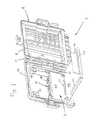
- a fibre optic interconnection enclosureis shown generally at 2 which generally includes an enclosure or housing member 4 and a fibre optic interconnection divider wall shown generally at 6.
- the enclosure 4includes a fixed housing portion 8 and a rotatable housing portion 10 that pivots generally about a hinge member 12 of the enclosure 4.
- a connection interfaceis shown generally as 14 which forms an interface between the telecom side and the user or system side as will be described herein.
- the housing enclosure 4is shown in the open position, without the divider wall 6.
- the enclosure portion 8is comprised of a back wall 16 which can be mounted flush to another surface, and includes mounting ears 18 having radiused surface 20 allowing the enclosure 4 to be alternatively mounted to a curved surface, such as a pole.
- the housing portion 8further includes along a lower edge thereof, arcuately shaped cable receiving grooves 22 spanned by openings such as 24, for receiving a cable tie for strain relief purposes.
- the housing portion 8further includes two cylindrical hinge sections 26, which lie in the same axis as hinge member 12.
- the housing portion 8further includes a perimetral wall at 28, which defines a recessed portion at 30, as will be described in greater detail herein.
- housing portion 10includes a perimetral wall at 32 defining a recessed surface at 34, and a further inner recessed surface at 36 defining an inner cavity at 38.
- the housing members 8 and 10are latched together by way of cooperating latches 40 and 42.
- Housing portions 8 and 10also include locking members 44 and 46, with an opening 48 aligned with threaded post 50 within compartment 52, and opening 54 aligned with compartment 56.
- sponge seal members 58 and 60are disposed at the lower edges of the housing members 8, 10, respectively.
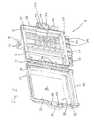
- the fibre optic interconnection divider wall 6includes a wall section 64 having a first side edge section 66 and a second side edge section 68 extending from the opposite side.
- the section 66includes a cable-receiving channel at 70 which communicates with an opening at 72.
- Extending from the channel section 70is a hinge member 74 including two snap latches shown generally at 76.
- Side edge section 68includes ears 80 extending therefrom, each of which have threaded lugs shown generally at 82.
- the fibre optic interconnection divider wall 6is further comprised of a back wall section 84 having a top surface 86 having a cut-out at 88, and side walls 90 and 92.
- wall 64includes mounting ears 98, 100 which cooperate as trunnions for rotatable tray 102.
- Tray 102is comprised of a wall section 104 having mounting tabs 106, 108 which cooperate with ears 100, 98, respectively, via rivets 110.
- Tray 102further includes inwardly curved wall sections 112, 114, 116, and 120, where flap portion 122 extends forwardly from wall 120 to cooperate within the opening 88 as described herein.
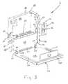
- the rotatable tray 102has three positions. The first position is a fully closed position where the tray 102 is rotated upwardly, such that wall 104 lies adjacent to wall 64. The second position is shown in Figure 3, where the wall is held in a substantially horizontal position.
- the third positionis such that the wall 102 is rotated fully downwardly such that walls 64, 104 would be co-planar.
- This positioningcould be accommodated in a number of ways, as appreciated by one of ordinary skill in the art.
- the wall portion 112could have a rear wall portion 124 which abuts wall 124, such that the tray 102 is held in the position of Figure 3, yet still be rotated downwardly.
- the rivets or the associated members 98, 100, 106, 108could be slotted so as to hold the tray 102 in a plurality of positions.
- a separate spring detentcould be positioned between the walls 64, 104 which would allow for various positions.
- interconnection interface 14is mounted to wall 130 which in turn is removably mounted to divider wall 6 by way of pin rivets 132.
- a fibre optic plug assemblyis shown generally at 140 which is insertable and latchably connected to the fibre optic connection interface 14.
- This known fibre optic connector plug 140is comprised of an inner plug body shown generally as 142 and an outer plug housing 144.
- the plug assemblyincludes an inner ceramic ferrule 146, which carries the fibre, and a polarizing lug 148 for alignment with the interface 14.
- This connector assemblyis available from the AMP Division of Tyco Electronics, and is known as the SC Series Fibre connector. This connector is also more fully described in U.S. Patent 5,542,015.
- connection interface 14is comprised of two identical halves 150 having flanges 152 which can be butted one to the other and fixed in place by such means as adhesive or ultrasonic welding.
- the connection interface 14further includes two identical latch members 154 in each fibre connector port 155 which receive between them a fibre aligning ferrule 156.
- the latch members 154further include latch projections 158, which retain the fibre plug assembly as is known in the art.
- the connection interface 14is held to the wall 130 by way of the rivets 132 as previously described.
- the identical halves 150include polarizing slots 160 for receiving the polarizing lug 148 on the plug assembly 140.
- the divider wall 6is insertable into the housing enclosure 4, by rotating the tray 102 upwardly to a position where flap member 122 is within the recess 88. The divider wall 6 can then be snapped in place by way of the individual latch members 76 being snapped in place against the cylindrical pins 26. This places the tray wall 104 adjacent to the back wall 16 of housing portion 8. Once snapped in place, the divider wall 6 can be rotated between the positions shown in Figures 1 and 6. It should also be appreciated that the divider wall 6 is also removable, for assembly purposes, as will be described herein.
- the fibre connectionscan be made as follows. First, an incoming fibre cable to be terminated is measured, by positioning the cable adjacent to the housing enclosure 4, and then cutting the cable, leaving adequate length for the splice termination. At this point, the fibre optic interconnection divider wall 6 can be removed from the housing enclosure 4, by unsnapping the hinges 74, and taking the divider wall 6 to a splicing bench.
- the divider wallhas two detented positions as described above, one which is approximately at a 90 degree angle, and one where the divider wall lay almost flat, that is at a 180 degree angle. The flat position allows for easy installation of the cable.
- the fibre connectors 140are also plugged into respective receptacles 14, with the connectors 140A having individual fibre cables such as 202 being accumulated within jacketed cables 204 and 206.
- pigtail 208is positioned adjacent to the divider wall 6, and cable tied thereto as described above.
- the individual cables 214 of the pigtail 208 and 202 of cables 204, 206are positioned adjacent to each other, and are then spliced together, as is well known in the art. After splicing, the spliced cables are positioned in the splice holder 212, as shown in Figure 7. It should be appreciated that after the splicing is completed, the divider wall and cables are returned to the housing enclosure 4 and snapped back in place.
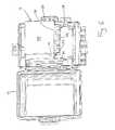
- the cablesare positioned within the housing enclosure such that the cables are coiled adjacent to wall 64 and then can turn to lie parallel and adjacent to wall 104.
- the cables 204, 206are positioned adjacent to wall 104, such that the cable is coiled between the sections 112, 114, 116, and 118. In other words, the fibre coil is beneath each of the sections 112, 114, 116 and 120.
- the tray 102is now rotated upwardly to its fully closed position, and then the entire divider wall 6 is rotated to the fully closed position, such that the ears 80 lie adjacent to the corresponding portions 52, 56.
- Individual plug connectors 140Bviewed in Figure 8, attached to cables 210, are pluggably connected to the connection interface 14.
- the connector interface 14defines a telecom service connection side 180, whereas the user/service side is defined at 182, as shown in Figure 6.
- the telecom side 180should be locked off from the user such that, when in the position of Figure 6, a special fastener can be positioned through the ear 80 and into threaded post 50 (Figure 2) such that the user cannot access this side of the connection interface. Rather, the user can only open the housing portion 10 to access the user side 182 as shown in Figure 6.
- the device described abovedefines a system which is both very space-conscious as well as versatile.
- the system having the rotatable tray 102allows the tray 102 to be latched in a fully locked position within the Network Interface Device 4 and movable between locked positions and unlocked positions.
- the trayIn the unlocked position, the tray can be rotated downward to a first detented position where the tray is horizontal where a technician can operate on the fibre splices or test the connections therein.
- the entire rotatable tray 102is removable for assembly of the fibre cable therein.
- the rotatable tray 102can be rotated to a fully rotated position where the walls 64 and 102 are substantially co-planar. In this position, the tray can be positioned on a workbench for splicing purposes.
- the receptacles 14are disposed in a substantially vertical orientation, this allows for easy disposition and coiling of the fibre cable as discussed with reference to Figure 7.
- the vertical positionalso prevents dirt and other debris from collecting in receptacles 182 ( Figure 6) if a certain header is not occupied by a mating plug connector.
- the two sponge seals 58, 60further prevent dirt and debris from collecting in the header 14.
- the divider wall 6could be designed as a stamped and formal member of a sheet steel, or could also be made from a plastic material, with a living hinge.
Landscapes
- Physics & Mathematics (AREA)
- General Physics & Mathematics (AREA)
- Optics & Photonics (AREA)
- Light Guides In General And Applications Therefor (AREA)
- Mechanical Coupling Of Light Guides (AREA)
- Optical Communication System (AREA)
- Cable Transmission Systems, Equalization Of Radio And Reduction Of Echo (AREA)
Abstract
Description
Claims (30)
- A fibre optic interconnection enclosure, comprising a housing enclosure, a fibre opticinterconnection divider wall dividing the housing enclosure into a telecom interconnectionarea and a user interconnection area, said interconnection divider wall having a connectioninterface to provide the interface between the telecom interconnection area and the userinterconnection area.
- The fibre optic interconnection enclosure of claim 1, wherein said interconnectiondivider wall is pivotal about a first hinge in said housing enclosure.
- The fibre optic interconnection enclosure of claim 2, wherein said housing enclosureis comprised of a first housing portion having a back wall, and a second housing portionhinged to said first housing portion and movable relative thereto about a second hinge.
- The fibre optic interconnection enclosure of claim 3, wherein said interconnectiondivider wall is pivotal between a closed position, where said divider wall lies adjacent tosaid back wall, to an open position where said interconnection divider wall is rotated awayfrom said back wall, and said telecom interconnection area of said connection interfacebeing accessible only when said interconnection divider wall is in said open position.
- The fibre optic interconnection enclosure of claim 4, wherein said divider wall, andfirst and second housing portions, all rotate about the same pivot axis.
- The fibre optic interconnection enclosure of claim 4, wherein said divider wallincludes an interface wall extending transversely of said pivot axis, said interface wallretaining said connection interface.
- The fibre optic interconnection enclosure of claim 6, wherein said interface wallextends in a horizontal plane, and said connection interface comprises a fibre optic header,with connection ports on opposite sides of said wall.
- The fibre optic interconnection enclosure of claim 7, wherein the mating axis for saidheader is vertical.
- The fibre optic interconnection enclosure of claim 8, wherein said divider wallincludes a rotatable work tray on the back side thereof, which pivots about a horizontal axis, whereby said divider wall can be rotated to its fully open position, and said work tray rotateddownwardly to a position adjacent to horizontal.
- The fibre optic interconnection enclosure of claim 9, wherein said work tray includesa fibre cable splice holder.
- The fibre optic interconnection enclosure of claim 9, wherein said work tray includesa retaining area for holding coiled fibre cable.
- A fibre optic interconnection enclosure, comprising a housing enclosure, a fibre opticinterconnection divider wall dividing the housing enclosure into a telecom interconnectionarea and a user interconnection area, said divider wall including a rotatable work tray whichpivots about a horizontal axis, whereby said rotatable work tray can be rotated downwardlyto a position adjacent to horizontal.
- The fibre optic interconnection enclosure of claim 12, wherein said interconnectiondivider wall is pivotal about a first hinge in said housing enclosure.
- The fibre optic interconnection enclosure of claim 13, wherein said housingenclosure is comprised of a first housing portion having a back wall, and a second housingportion hinged to said first housing portion and movable relative thereto about a secondhinge.
- The fibre optic interconnection enclosure of claim 14, wherein said interconnectiondivider wall is also hinged relative to said first and second housing portions, and rotatablerelative thereto.
- The fibre optic interconnection enclosure of claim 15, wherein said interconnectiondivider wall, and first and second housing portions, all rotate about the same pivot axis.
- The fibre optic interconnection enclosure of claim 16, wherein said interconnectiondivider wall includes an interface wall extending transversely of said pivot axis.
- The fibre optic interconnection enclosure of claim 12, wherein said interconnectiondivider wall has a connection interface to provide the interface between the telecominterconnection area and the user interconnection area.
- The fibre optic interconnection enclosure of claim 18, wherein said interconnectiondivider wall extends in a horizontal plane, and said connection interface comprises a fibreoptic header having header halves on opposite sides of said plane.
- The fibre optic interconnection enclosure of claim 19, wherein the mating axis forsaid header is vertical.
- The fibre optic interconnection enclosure of claim 12, wherein said rotatable worktray is positioned on back side of said divider wall and pivots about a horizontal axis,whereby said divider wall can be rotated to its fully open position, and said work tray rotateddownwardly to a position adjacent to horizontal.
- The fibre optic interconnection enclosure of claim 21, wherein said work trayincludes a fibre cable splice holder.
- The fibre optic interconnection enclosure of claim 21, wherein said work trayincludes a retaining area for holding coiled fibre cable.
- A fibre optic interconnection enclosure, comprising a housing enclosure, aconnection interface defining an interface between a telecom interconnection and a userinterconnection, and a rotatable work tray which pivots about a horizontal axis, wherebysaid rotatable work tray can be rotated downwardly to a position adjacent to horizontal.
- The fibre optic interconnection enclosure of claim 24, further comprising a fibreoptic interconnection divider wall dividing the housing enclosure into a telecominterconnection area and a user interconnection area.
- The fibre optic interconnection enclosure of claim 25, wherein said rotatable worktray is positioned on a back side of said divider wall and pivots about a horizontal axis,whereby said divider wall can be rotated to its fully open position, and said work tray rotateddownwardly to a position adjacent to horizontal.
- The fibre optic interconnection enclosure of claim 26, wherein said interconnectiondivider wall has a connection interface to provide the interface between the telecominterconnection area and the system interconnection area.
- The fibre optic interconnection enclosure of claim 27, wherein said divider wallincludes an interface wall which extends in a horizontal plane, and said connection member comprises a fibre optic header having header halves mounted to said interface wall, withconnector ports on opposite side of said interface wall.
- The fibre optic interconnection enclosure of claim 24, wherein said work trayincludes a fibre cable splice holder.
- The fibre optic interconnection enclosure of claim 24, wherein said work trayincludes a retaining area for holding coiled fibre cable.
Applications Claiming Priority (2)
| Application Number | Priority Date | Filing Date | Title |
|---|---|---|---|
| US704098 | 2000-11-01 | ||
| US09/704,098US6661961B1 (en) | 2000-11-01 | 2000-11-01 | Fiber low profile network interface device |
Publications (3)
| Publication Number | Publication Date |
|---|---|
| EP1203974A2true EP1203974A2 (en) | 2002-05-08 |
| EP1203974A3 EP1203974A3 (en) | 2004-06-09 |
| EP1203974B1 EP1203974B1 (en) | 2006-02-01 |
Family
ID=24828042
Family Applications (1)
| Application Number | Title | Priority Date | Filing Date |
|---|---|---|---|
| EP01204160AExpired - LifetimeEP1203974B1 (en) | 2000-11-01 | 2001-10-30 | Low profile optical fibre network interface enclosure |
Country Status (7)
| Country | Link |
|---|---|
| US (1) | US6661961B1 (en) |
| EP (1) | EP1203974B1 (en) |
| AT (1) | ATE317132T1 (en) |
| CA (1) | CA2360705A1 (en) |
| DE (1) | DE60116952T2 (en) |
| DK (1) | DK1203974T3 (en) |
| ES (1) | ES2256156T3 (en) |
Cited By (70)
| Publication number | Priority date | Publication date | Assignee | Title |
|---|---|---|---|---|
| EP1316829A3 (en)* | 2001-11-30 | 2005-03-02 | Corning Cable Systems LLC | Optical fiber distribution terminal for network access point |
| WO2004110122A3 (en)* | 2003-05-30 | 2005-07-21 | Adc Telecommunications Inc | Optical fiber distribution frame with rotating panel |
| WO2006076115A1 (en)* | 2005-01-13 | 2006-07-20 | Corning Cable Systems Llc | Network interface device having integral slack storage compartment |
| WO2008106126A1 (en)* | 2007-02-28 | 2008-09-04 | Corning Cable Systems Llc | Fiber optic splice trays |
| WO2008137389A1 (en)* | 2007-05-07 | 2008-11-13 | Adc Telecommunications, Inc. | Modular optical wall box enclosure |
| WO2009089327A3 (en)* | 2008-01-09 | 2009-08-27 | Adc Telecommunications, Inc. | Wall box adapted to be mounted at a mid-span access location of a telecommunications cable |
| WO2009149814A1 (en)* | 2008-06-09 | 2009-12-17 | Adc Gmbh | Termination box for glass fiber cables, and panel |
| WO2010055451A1 (en)* | 2008-11-12 | 2010-05-20 | Raychem Shanghai Cable Accessories Ltd | Optical cable closure and method of using the same |
| US7751675B2 (en) | 2007-12-11 | 2010-07-06 | Adc Telecommunications, Inc. | Wall box adapted to be mounted at a mid-span access location of a telecommunications cable |
| WO2011091824A1 (en)* | 2010-02-01 | 2011-08-04 | Adc Gmbh | Distribution cabinet for optical fibre cables |
| US8213760B2 (en) | 2009-01-28 | 2012-07-03 | Adc Telecommunications, Inc. | Fiber optic enclosure |
| US8315498B2 (en) | 2008-04-11 | 2012-11-20 | Adc Telecommunications, Inc. | Fiber management panel |
| US8335429B2 (en) | 2006-03-13 | 2012-12-18 | British Telecommunications Public Limited Company | Network termination apparatus |
| US8433171B2 (en) | 2009-06-19 | 2013-04-30 | Corning Cable Systems Llc | High fiber optic cable packing density apparatus |
| US8467651B2 (en) | 2009-09-30 | 2013-06-18 | Ccs Technology Inc. | Fiber optic terminals configured to dispose a fiber optic connection panel(s) within an optical fiber perimeter and related methods |
| US8520996B2 (en) | 2009-03-31 | 2013-08-27 | Corning Cable Systems Llc | Removably mountable fiber optic terminal |
| US8538226B2 (en) | 2009-05-21 | 2013-09-17 | Corning Cable Systems Llc | Fiber optic equipment guides and rails configured with stopping position(s), and related equipment and methods |
| US8542973B2 (en) | 2010-04-23 | 2013-09-24 | Ccs Technology, Inc. | Fiber optic distribution device |
| US8593828B2 (en) | 2010-02-04 | 2013-11-26 | Corning Cable Systems Llc | Communications equipment housings, assemblies, and related alignment features and methods |
| US8625950B2 (en) | 2009-12-18 | 2014-01-07 | Corning Cable Systems Llc | Rotary locking apparatus for fiber optic equipment trays and related methods |
| US8660397B2 (en) | 2010-04-30 | 2014-02-25 | Corning Cable Systems Llc | Multi-layer module |
| US8662760B2 (en) | 2010-10-29 | 2014-03-04 | Corning Cable Systems Llc | Fiber optic connector employing optical fiber guide member |
| US8699838B2 (en) | 2009-05-14 | 2014-04-15 | Ccs Technology, Inc. | Fiber optic furcation module |
| US8705926B2 (en) | 2010-04-30 | 2014-04-22 | Corning Optical Communications LLC | Fiber optic housings having a removable top, and related components and methods |
| US8712206B2 (en) | 2009-06-19 | 2014-04-29 | Corning Cable Systems Llc | High-density fiber optic modules and module housings and related equipment |
| US8718436B2 (en) | 2010-08-30 | 2014-05-06 | Corning Cable Systems Llc | Methods, apparatuses for providing secure fiber optic connections |
| US8792767B2 (en) | 2010-04-16 | 2014-07-29 | Ccs Technology, Inc. | Distribution device |
| US8798427B2 (en) | 2007-09-05 | 2014-08-05 | Corning Cable Systems Llc | Fiber optic terminal assembly |
| US8879882B2 (en) | 2008-10-27 | 2014-11-04 | Corning Cable Systems Llc | Variably configurable and modular local convergence point |
| US8879881B2 (en) | 2010-04-30 | 2014-11-04 | Corning Cable Systems Llc | Rotatable routing guide and assembly |
| US8909019B2 (en) | 2012-10-11 | 2014-12-09 | Ccs Technology, Inc. | System comprising a plurality of distribution devices and distribution device |
| US8913866B2 (en) | 2010-03-26 | 2014-12-16 | Corning Cable Systems Llc | Movable adapter panel |
| US8953924B2 (en) | 2011-09-02 | 2015-02-10 | Corning Cable Systems Llc | Removable strain relief brackets for securing fiber optic cables and/or optical fibers to fiber optic equipment, and related assemblies and methods |
| US8965168B2 (en) | 2010-04-30 | 2015-02-24 | Corning Cable Systems Llc | Fiber management devices for fiber optic housings, and related components and methods |
| US8989547B2 (en) | 2011-06-30 | 2015-03-24 | Corning Cable Systems Llc | Fiber optic equipment assemblies employing non-U-width-sized housings and related methods |
| US8985862B2 (en) | 2013-02-28 | 2015-03-24 | Corning Cable Systems Llc | High-density multi-fiber adapter housings |
| US8995812B2 (en) | 2012-10-26 | 2015-03-31 | Ccs Technology, Inc. | Fiber optic management unit and fiber optic distribution device |
| US9004778B2 (en) | 2012-06-29 | 2015-04-14 | Corning Cable Systems Llc | Indexable optical fiber connectors and optical fiber connector arrays |
| US9008485B2 (en) | 2011-05-09 | 2015-04-14 | Corning Cable Systems Llc | Attachment mechanisms employed to attach a rear housing section to a fiber optic housing, and related assemblies and methods |
| US9020320B2 (en) | 2008-08-29 | 2015-04-28 | Corning Cable Systems Llc | High density and bandwidth fiber optic apparatuses and related equipment and methods |
| US9022814B2 (en) | 2010-04-16 | 2015-05-05 | Ccs Technology, Inc. | Sealing and strain relief device for data cables |
| US9042702B2 (en) | 2012-09-18 | 2015-05-26 | Corning Cable Systems Llc | Platforms and systems for fiber optic cable attachment |
| US9038832B2 (en) | 2011-11-30 | 2015-05-26 | Corning Cable Systems Llc | Adapter panel support assembly |
| US9049500B2 (en) | 2012-08-31 | 2015-06-02 | Corning Cable Systems Llc | Fiber optic terminals, systems, and methods for network service management |
| US9059578B2 (en) | 2009-02-24 | 2015-06-16 | Ccs Technology, Inc. | Holding device for a cable or an assembly for use with a cable |
| US9075217B2 (en) | 2010-04-30 | 2015-07-07 | Corning Cable Systems Llc | Apparatuses and related components and methods for expanding capacity of fiber optic housings |
| US9081164B2 (en) | 2011-08-24 | 2015-07-14 | Adc Telecommunications, Inc. | Fiber management panel |
| US9116324B2 (en) | 2010-10-29 | 2015-08-25 | Corning Cable Systems Llc | Stacked fiber optic modules and fiber optic equipment configured to support stacked fiber optic modules |
| US9213161B2 (en) | 2010-11-05 | 2015-12-15 | Corning Cable Systems Llc | Fiber body holder and strain relief device |
| US9219546B2 (en) | 2011-12-12 | 2015-12-22 | Corning Optical Communications LLC | Extremely high frequency (EHF) distributed antenna systems, and related components and methods |
| US9250409B2 (en) | 2012-07-02 | 2016-02-02 | Corning Cable Systems Llc | Fiber-optic-module trays and drawers for fiber-optic equipment |
| US9279951B2 (en) | 2010-10-27 | 2016-03-08 | Corning Cable Systems Llc | Fiber optic module for limited space applications having a partially sealed module sub-assembly |
| US9323020B2 (en) | 2008-10-09 | 2016-04-26 | Corning Cable Systems (Shanghai) Co. Ltd | Fiber optic terminal having adapter panel supporting both input and output fibers from an optical splitter |
| US9519118B2 (en) | 2010-04-30 | 2016-12-13 | Corning Optical Communications LLC | Removable fiber management sections for fiber optic housings, and related components and methods |
| US9547145B2 (en) | 2010-10-19 | 2017-01-17 | Corning Optical Communications LLC | Local convergence point for multiple dwelling unit fiber optic distribution network |
| US9547144B2 (en) | 2010-03-16 | 2017-01-17 | Corning Optical Communications LLC | Fiber optic distribution network for multiple dwelling units |
| US9632270B2 (en) | 2010-04-30 | 2017-04-25 | Corning Optical Communications LLC | Fiber optic housings configured for tool-less assembly, and related components and methods |
| US9645317B2 (en) | 2011-02-02 | 2017-05-09 | Corning Optical Communications LLC | Optical backplane extension modules, and related assemblies suitable for establishing optical connections to information processing modules disposed in equipment racks |
| US9720195B2 (en) | 2010-04-30 | 2017-08-01 | Corning Optical Communications LLC | Apparatuses and related components and methods for attachment and release of fiber optic housings to and from an equipment rack |
| US10025055B2 (en) | 2014-09-16 | 2018-07-17 | CommScope Connectivity Belgium BVBA | Multi-positionable telecommunications tray |
| US10094996B2 (en) | 2008-08-29 | 2018-10-09 | Corning Optical Communications, Llc | Independently translatable modules and fiber optic equipment trays in fiber optic equipment |
| US10110307B2 (en) | 2012-03-02 | 2018-10-23 | Corning Optical Communications LLC | Optical network units (ONUs) for high bandwidth connectivity, and related components and methods |
| US10175440B2 (en) | 2013-03-19 | 2019-01-08 | Adc Czech Republic, S.R.O. | Moveable bend control and patch cord support for telecommunications panel |
| US10209470B2 (en) | 2014-09-16 | 2019-02-19 | CommScope Connectivity Belgium BVBA | Telecommunications tray with a cable routing path extending through a pivot hinge |
| US10254496B2 (en) | 2015-04-23 | 2019-04-09 | CommScope Connectivity Belgium BVBA | Telecommunications panel assembly with movable adapters |
| US10502917B2 (en) | 2014-09-16 | 2019-12-10 | CommScope Connectivity Belgium BVBA | Telecommunications tray assembly |
| WO2021155182A3 (en)* | 2020-01-29 | 2021-09-23 | Afl Telecommunications Llc | Terminal enclosure for a telecommunications system |
| US11175469B2 (en) | 2017-10-26 | 2021-11-16 | CommScope Connectivity Belgium BVBA | Telecommunications system |
| US11294135B2 (en) | 2008-08-29 | 2022-04-05 | Corning Optical Communications LLC | High density and bandwidth fiber optic apparatuses and related equipment and methods |
| PL130284U1 (en)* | 2021-09-23 | 2023-03-27 | Fca Spółka Z Ograniczoną Odpowiedzialnością | Subscriber socket |
Families Citing this family (83)
| Publication number | Priority date | Publication date | Assignee | Title |
|---|---|---|---|---|
| US6760531B1 (en) | 1999-03-01 | 2004-07-06 | Adc Telecommunications, Inc. | Optical fiber distribution frame with outside plant enclosure |
| US7142764B2 (en) | 2003-03-20 | 2006-11-28 | Tyco Electronics Corporation | Optical fiber interconnect cabinets, termination modules and fiber connectivity management for the same |
| US6792191B1 (en)* | 2003-04-22 | 2004-09-14 | Corning Cable Systems Llc | Local convergence cabinet |
| US7198409B2 (en) | 2003-06-30 | 2007-04-03 | Adc Telecommunications, Inc. | Fiber optic connector holder and method |
| US7233731B2 (en) | 2003-07-02 | 2007-06-19 | Adc Telecommunications, Inc. | Telecommunications connection cabinet |
| US6983095B2 (en) | 2003-11-17 | 2006-01-03 | Fiber Optic Network Solutions Corporation | Systems and methods for managing optical fibers and components within an enclosure in an optical communications network |
| US7369741B2 (en) | 2003-11-17 | 2008-05-06 | Fiber Optics Network Solutions Corp. | Storage adapter with dust cap posts |
| US7346253B2 (en)* | 2003-12-24 | 2008-03-18 | Corning Cable Systems Llc | Fiber optic drop cable slack storage receptacle |
| US7001084B2 (en)* | 2003-12-30 | 2006-02-21 | 3M Innovative Properties Company | Fiber splice device |
| US7120347B2 (en)* | 2004-01-27 | 2006-10-10 | Corning Cable Systems Llc | Multi-port optical connection terminal |
| US7013074B2 (en)* | 2004-02-06 | 2006-03-14 | Corning Cable Systems Llc | Optical connection closure having at least one connector port |
| US6926449B1 (en)* | 2004-02-23 | 2005-08-09 | Corning Cable Systems Llc | Connector port for network interface device |
| US20050254757A1 (en)* | 2004-02-23 | 2005-11-17 | Ferretti Vincent E Iii | Connector port for network interface device |
| CA2558996A1 (en) | 2004-03-08 | 2005-09-22 | Adc Telecommunications, Inc. | Fiber access terminal |
| US7218827B2 (en) | 2004-06-18 | 2007-05-15 | Adc Telecommunications, Inc. | Multi-position fiber optic connector holder and method |
| GB0423743D0 (en) | 2004-10-26 | 2004-11-24 | Tyco Electronics Raychem Nv | A signal distribution assembly and a connector holder for use therewith |
| US7489849B2 (en) | 2004-11-03 | 2009-02-10 | Adc Telecommunications, Inc. | Fiber drop terminal |
| US20060153362A1 (en)* | 2005-01-13 | 2006-07-13 | Bloodworth Stephen G | Network interface device for fiber optic communications network |
| US7194181B2 (en) | 2005-03-31 | 2007-03-20 | Adc Telecommunications, Inc. | Adapter block including connector storage |
| US7623749B2 (en) | 2005-08-30 | 2009-11-24 | Adc Telecommunications, Inc. | Fiber distribution hub with modular termination blocks |
| US7720343B2 (en) | 2006-02-13 | 2010-05-18 | Adc Telecommunications, Inc. | Fiber distribution hub with swing frame and modular termination panels |
| US7816602B2 (en) | 2006-02-13 | 2010-10-19 | Adc Telecommunications, Inc. | Fiber distribution hub with outside accessible grounding terminals |
| US7760984B2 (en) | 2006-05-04 | 2010-07-20 | Adc Telecommunications, Inc. | Fiber distribution hub with swing frame and wrap-around doors |
| US8135256B2 (en) | 2006-12-01 | 2012-03-13 | Adc Telecommunications, Inc. | Network interface device |
| US7349616B1 (en) | 2007-01-12 | 2008-03-25 | Corning Cable Systems Llc | Fiber optic local convergence points for multiple dwelling units |
| DE102007010863B4 (en)* | 2007-03-01 | 2009-01-08 | Adc Gmbh | Sleeve for fiber optic cable |
| DE102007010853B4 (en)* | 2007-03-01 | 2009-01-29 | Adc Gmbh | Distributor device for optical waveguides |
| DE102007010855B4 (en)* | 2007-03-01 | 2009-01-08 | Adc Gmbh | Support system for a distributor device for optical waveguides |
| DE102007010854B4 (en)* | 2007-03-01 | 2009-01-08 | Adc Gmbh | Console for a distributor device for optical fiber cables |
| US7558458B2 (en) | 2007-03-08 | 2009-07-07 | Adc Telecommunications, Inc. | Universal bracket for mounting a drop terminal |
| US7522805B2 (en)* | 2007-03-09 | 2009-04-21 | Adc Telecommunications, Inc. | Wall mount distribution arrangement |
| US7512304B2 (en) | 2007-03-23 | 2009-03-31 | Adc Telecommunications, Inc. | Drop terminal with anchor block for retaining a stub cable |
| US7496269B1 (en) | 2007-04-12 | 2009-02-24 | Adc Gmbh | Fiber optic enclosure |
| US7664360B2 (en)* | 2007-04-17 | 2010-02-16 | Corning Cable Systems Llc | Fiber optic drop terminal mounting plate |
| US7715679B2 (en) | 2007-05-07 | 2010-05-11 | Adc Telecommunications, Inc. | Fiber optic enclosure with external cable spool |
| US7756379B2 (en) | 2007-08-06 | 2010-07-13 | Adc Telecommunications, Inc. | Fiber optic enclosure with internal cable spool |
| US7869682B2 (en) | 2007-09-05 | 2011-01-11 | Adc Telecommunications, Inc. | Fiber optic enclosure with tear-away spool |
| US7740409B2 (en) | 2007-09-19 | 2010-06-22 | Corning Cable Systems Llc | Multi-port optical connection terminal |
| US7903923B2 (en) | 2007-10-09 | 2011-03-08 | Adc Telecommunications, Inc. | Drop terminal releasable engagement mechanism |
| EP2198328B1 (en) | 2007-10-09 | 2018-09-26 | ADC Telecommunications, INC. | Mini drop terminal |
| US7751672B2 (en) | 2007-10-31 | 2010-07-06 | Adc Telecommunications, Inc. | Low profile fiber distribution hub |
| US8229265B2 (en) | 2007-11-21 | 2012-07-24 | Adc Telecommunications, Inc. | Fiber distribution hub with multiple configurations |
| US7889961B2 (en) | 2008-03-27 | 2011-02-15 | Corning Cable Systems Llc | Compact, high-density adapter module, housing assembly and frame assembly for optical fiber telecommunications |
| ES2560802T3 (en) | 2008-08-27 | 2016-02-22 | Adc Telecommunications, Inc. | Fiber optic adapter with integrally molded bushing alignment structure |
| US8265447B2 (en) | 2008-09-16 | 2012-09-11 | Adc Telecommunications, Inc. | Modular fiber optic enclosure with external cable spool |
| WO2010059623A1 (en) | 2008-11-21 | 2010-05-27 | Adc Telecommunications, Inc. | Fiber optic telecommunications module |
| US20110013875A1 (en)* | 2009-07-16 | 2011-01-20 | Adc Telecommunications, Inc. | Fiber optic enclosure with adapter bulkhead positioned beneath pivotal splice tray |
| CN102870021B (en) | 2010-03-02 | 2015-03-11 | 蒂安电子服务有限责任公司 | Fibre-optic telecommunication module |
| US8649649B2 (en) | 2010-03-03 | 2014-02-11 | Adc Telecommunications, Inc. | Fiber distribution hub with connectorized stub cables |
| DE102010010428B4 (en) | 2010-03-05 | 2012-07-19 | Adc Gmbh | Connection box for fiber optic cable |
| US8837940B2 (en) | 2010-04-14 | 2014-09-16 | Adc Telecommunications, Inc. | Methods and systems for distributing fiber optic telecommunication services to local areas and for supporting distributed antenna systems |
| WO2011140461A2 (en) | 2010-05-07 | 2011-11-10 | Adc Telecommunications, Inc. | Fiber distribution hub with pass-through interfaces |
| US20120008257A1 (en)* | 2010-07-06 | 2012-01-12 | 3M Innovative Properties Company | Cell tower wiring junction box |
| WO2012058391A1 (en) | 2010-10-28 | 2012-05-03 | Corning Cable Systems Llc | Impact resistant fiber optic enclosures and related methods |
| CA2836133A1 (en) | 2011-05-17 | 2012-11-22 | 3M Innovative Properties Company | Converged in-building network |
| CA2877896C (en)* | 2011-06-24 | 2020-07-21 | Adc Telecommunications, Inc. | Fiber termination enclosure with modular plate assemblies |
| US9417418B2 (en) | 2011-09-12 | 2016-08-16 | Commscope Technologies Llc | Flexible lensed optical interconnect device for signal distribution |
| RU2611105C2 (en) | 2011-10-07 | 2017-02-21 | Адс Телекоммьюникейшнз, Инк. | Fibre-optic cartridge, system and method |
| US9069151B2 (en) | 2011-10-26 | 2015-06-30 | Corning Cable Systems Llc | Composite cable breakout assembly |
| US8873926B2 (en) | 2012-04-26 | 2014-10-28 | Corning Cable Systems Llc | Fiber optic enclosures employing clamping assemblies for strain relief of cables, and related assemblies and methods |
| US9146362B2 (en) | 2012-09-21 | 2015-09-29 | Adc Telecommunications, Inc. | Insertion and removal tool for a fiber optic ferrule alignment sleeve |
| US9146374B2 (en) | 2012-09-28 | 2015-09-29 | Adc Telecommunications, Inc. | Rapid deployment packaging for optical fiber |
| NZ706687A (en) | 2012-09-28 | 2017-09-29 | Adc Telecommunications Inc | Fiber optic cassette |
| US9223094B2 (en) | 2012-10-05 | 2015-12-29 | Tyco Electronics Nederland Bv | Flexible optical circuit, cassettes, and methods |
| US9435975B2 (en) | 2013-03-15 | 2016-09-06 | Commscope Technologies Llc | Modular high density telecommunications frame and chassis system |
| WO2015116672A1 (en) | 2014-01-28 | 2015-08-06 | Adc Telecommunications, Inc. | Slidable fiber optic connection module with cable slack management |
| US9494758B2 (en) | 2014-04-03 | 2016-11-15 | Commscope Technologies Llc | Fiber optic distribution system |
| US9341801B2 (en) | 2014-05-27 | 2016-05-17 | 3M Innovative Properties Company | Fiber management assemblies and trays and network interface devices incorporating such assemblies and trays |
| WO2016049242A1 (en) | 2014-09-23 | 2016-03-31 | Ppc Broadband, Inc. | Universal multi-purpose compartmentalized telecommunications box |
| US9882362B2 (en)* | 2014-09-23 | 2018-01-30 | Ppc Broadband, Inc. | Enclosure for controling access to different telecommunication components |
| US10976512B2 (en)* | 2014-09-23 | 2021-04-13 | Ppc Broadband, Inc. | House box with mounting surface for mounted access |
| US10509187B2 (en)* | 2014-09-23 | 2019-12-17 | Ppc Broadband, Inc. | Universal multi-purpose compartmentalized telecommunications box |
| US9612416B2 (en)* | 2014-12-31 | 2017-04-04 | All Systems Broadband, Inc. | Fiber demarcation box for layering and storing coiled fiber optic cabling |
| MX2017014377A (en) | 2015-05-15 | 2018-08-15 | Adc Telecommunications Shanghai Distrib Co Ltd | Alignment sleeve assembly and optical fibre adapter. |
| WO2016191094A1 (en)* | 2015-05-27 | 2016-12-01 | 3M Innovative Properties Company | Fiber management assemblies and network interface devices incorporating such assemblies |
| US11409068B2 (en) | 2017-10-02 | 2022-08-09 | Commscope Technologies Llc | Fiber optic circuit and preparation method |
| WO2019209613A1 (en)* | 2018-04-23 | 2019-10-31 | Commscope Technologies Llc | Telecommunications enclosure with modular locking system |
| US10230226B1 (en) | 2018-07-03 | 2019-03-12 | Afl Telecommunications Llc | Network interface devices |
| EP3948383A4 (en)* | 2019-03-29 | 2022-12-07 | CommScope Technologies LLC | Tray hinge interface system |
| BR102019014363A2 (en)* | 2019-07-11 | 2021-01-19 | Furukawa Electric Latam S.A. | termination box and optical branch |
| US12339511B2 (en) | 2020-03-31 | 2025-06-24 | Commscope Technologies Llc | Fiber optic cable management systems and methods |
| EP4139728A4 (en)* | 2020-04-23 | 2024-06-19 | PPC Broadband, Inc. | ETHERNET BRIDGE MOUNTING ARRANGEMENT |
| CN220795544U (en)* | 2023-09-12 | 2024-04-16 | 宁波市超卓光通讯技术有限公司 | Optical fiber splitter box |
Family Cites Families (14)
| Publication number | Priority date | Publication date | Assignee | Title |
|---|---|---|---|---|
| US4595255A (en)* | 1983-08-24 | 1986-06-17 | Fiberlan, Inc. | Optical fiber wiring center |
| US4824196A (en)* | 1987-05-26 | 1989-04-25 | Minnesota Mining And Manufacturing Company | Optical fiber distribution panel |
| US4949376A (en)* | 1989-06-15 | 1990-08-14 | Keptel, Inc. | Telephone network interface apparatus |
| DE4119829A1 (en)* | 1991-06-15 | 1992-12-17 | Rose Walter Gmbh & Co Kg | DEVICE FOR DIVIDING LIGHTWAVE GUIDE CABLES OR - Veins |
| US5367598A (en)* | 1993-10-21 | 1994-11-22 | Nec America, Inc. | Interface chassis for fiber optic transport system |
| JP3419953B2 (en)* | 1995-04-19 | 2003-06-23 | 住友電気工業株式会社 | Optical cable connection box |
| FR2734651B1 (en)* | 1995-05-24 | 1997-06-20 | Alcatel Cable Interface | FIBER OPTIC CONNECTION BOX |
| US5668911A (en)* | 1996-07-11 | 1997-09-16 | Northern Telecom Limited | Storage holders for optical fibers |
| US5901220A (en)* | 1997-02-28 | 1999-05-04 | The Whitaker Corporation | Network interface device |
| US5802237A (en)* | 1997-04-18 | 1998-09-01 | Minnesota Mining And Manufacturing Company | Optical fiber organizer |
| DE19740246C1 (en)* | 1997-09-12 | 1999-02-04 | Felten & Guilleaume Ag | Housing for connecting power cables and light conductors |
| JP3130021B1 (en)* | 1999-08-06 | 2001-01-31 | 盟友技研株式会社 | Relay connection device |
| US6193420B1 (en)* | 1999-08-13 | 2001-02-27 | Lucent Technologies Inc. | Shielded optical fiber adaptor |
| US6385381B1 (en)* | 1999-09-21 | 2002-05-07 | Lucent Technologies Inc. | Fiber optic interconnection combination closure |
- 2000
- 2000-11-01USUS09/704,098patent/US6661961B1/ennot_activeExpired - Lifetime
- 2001
- 2001-10-30ESES01204160Tpatent/ES2256156T3/ennot_activeExpired - Lifetime
- 2001-10-30DEDE60116952Tpatent/DE60116952T2/ennot_activeExpired - Lifetime
- 2001-10-30EPEP01204160Apatent/EP1203974B1/ennot_activeExpired - Lifetime
- 2001-10-30ATAT01204160Tpatent/ATE317132T1/enactive
- 2001-10-30DKDK01204160Tpatent/DK1203974T3/enactive
- 2001-10-31CACA002360705Apatent/CA2360705A1/ennot_activeAbandoned
Cited By (119)
| Publication number | Priority date | Publication date | Assignee | Title |
|---|---|---|---|---|
| EP1316829A3 (en)* | 2001-11-30 | 2005-03-02 | Corning Cable Systems LLC | Optical fiber distribution terminal for network access point |
| EP2241916A1 (en)* | 2003-05-30 | 2010-10-20 | ADC Telecommunications, Inc. | Optical fiber distribution frame with rotating panel |
| WO2004110122A3 (en)* | 2003-05-30 | 2005-07-21 | Adc Telecommunications Inc | Optical fiber distribution frame with rotating panel |
| US7102884B2 (en) | 2003-05-30 | 2006-09-05 | Adc Telecommunications, Inc. | Fiber containment system |
| US8144457B2 (en) | 2003-05-30 | 2012-03-27 | Adc Telecommunications, Inc. | Fiber containment system |
| WO2006076115A1 (en)* | 2005-01-13 | 2006-07-20 | Corning Cable Systems Llc | Network interface device having integral slack storage compartment |
| US8335429B2 (en) | 2006-03-13 | 2012-12-18 | British Telecommunications Public Limited Company | Network termination apparatus |
| WO2008106126A1 (en)* | 2007-02-28 | 2008-09-04 | Corning Cable Systems Llc | Fiber optic splice trays |
| WO2008137389A1 (en)* | 2007-05-07 | 2008-11-13 | Adc Telecommunications, Inc. | Modular optical wall box enclosure |
| US7817895B2 (en) | 2007-05-07 | 2010-10-19 | Adc Telecommunications, Inc. | Modular optical wall box enclosure |
| US7493003B2 (en) | 2007-05-07 | 2009-02-17 | Adc Telecommunications, Inc. | Modular optical wall box enclosure |
| US8798427B2 (en) | 2007-09-05 | 2014-08-05 | Corning Cable Systems Llc | Fiber optic terminal assembly |
| US7751675B2 (en) | 2007-12-11 | 2010-07-06 | Adc Telecommunications, Inc. | Wall box adapted to be mounted at a mid-span access location of a telecommunications cable |
| US10422970B2 (en) | 2008-01-09 | 2019-09-24 | Commscope Technologies Llc | Wall box adapted to be mounted at a mid-span access location of a telecommunications cable |
| US9557504B2 (en) | 2008-01-09 | 2017-01-31 | Commscope Technologies Llc | Wall box adapted to be mounted at a mid-span access location of a telecommunications cable |
| US8111966B2 (en) | 2008-01-09 | 2012-02-07 | Adc Telecommunications, Inc. | Wall box adapted to be mounted at a mid-span access location of a telecommunications cable |
| US11036018B2 (en) | 2008-01-09 | 2021-06-15 | Commscope Technologies Llc | Wall box adapted to be mounted at a mid-span access location of a telecommunications cable |
| WO2009089327A3 (en)* | 2008-01-09 | 2009-08-27 | Adc Telecommunications, Inc. | Wall box adapted to be mounted at a mid-span access location of a telecommunications cable |
| CN101965531B (en)* | 2008-01-09 | 2014-06-04 | Adc电信公司 | Wall box suitable for fitting at mid-span entry locations for communication cables |
| US11592636B2 (en) | 2008-01-09 | 2023-02-28 | Commscope Technologies Llc | Wall box adapted to be mounted at a mid-span access location of a telecommunications cable |
| US8837894B2 (en) | 2008-01-09 | 2014-09-16 | Adc Telecommunications, Inc. | Wall box adapted to be mounted at a mid-span access location of a telecommunications cable |
| US8315498B2 (en) | 2008-04-11 | 2012-11-20 | Adc Telecommunications, Inc. | Fiber management panel |
| US8509586B2 (en) | 2008-06-09 | 2013-08-13 | Adc Gmbh | Terminal box for fiberoptic cables and panel |
| WO2009149814A1 (en)* | 2008-06-09 | 2009-12-17 | Adc Gmbh | Termination box for glass fiber cables, and panel |
| US11609396B2 (en) | 2008-08-29 | 2023-03-21 | Corning Optical Communications LLC | High density and bandwidth fiber optic apparatuses and related equipment and methods |
| US10416405B2 (en) | 2008-08-29 | 2019-09-17 | Corning Optical Communications LLC | Independently translatable modules and fiber optic equipment trays in fiber optic equipment |
| US10564378B2 (en) | 2008-08-29 | 2020-02-18 | Corning Optical Communications LLC | High density and bandwidth fiber optic apparatuses and related equipment and methods |
| US12072545B2 (en) | 2008-08-29 | 2024-08-27 | Corning Optical Communications LLC | High density and bandwidth fiber optic apparatuses and related equipment and methods |
| US11754796B2 (en) | 2008-08-29 | 2023-09-12 | Corning Optical Communications LLC | Independently translatable modules and fiber optic equipment trays in fiber optic equipment |
| US10852499B2 (en) | 2008-08-29 | 2020-12-01 | Corning Optical Communications LLC | High density and bandwidth fiber optic apparatuses and related equipment and methods |
| US9910236B2 (en) | 2008-08-29 | 2018-03-06 | Corning Optical Communications LLC | High density and bandwidth fiber optic apparatuses and related equipment and methods |
| US10094996B2 (en) | 2008-08-29 | 2018-10-09 | Corning Optical Communications, Llc | Independently translatable modules and fiber optic equipment trays in fiber optic equipment |
| US10120153B2 (en) | 2008-08-29 | 2018-11-06 | Corning Optical Communications, Llc | Independently translatable modules and fiber optic equipment trays in fiber optic equipment |
| US10126514B2 (en) | 2008-08-29 | 2018-11-13 | Corning Optical Communications, Llc | Independently translatable modules and fiber optic equipment trays in fiber optic equipment |
| US10222570B2 (en) | 2008-08-29 | 2019-03-05 | Corning Optical Communications LLC | Independently translatable modules and fiber optic equipment trays in fiber optic equipment |
| US10606014B2 (en) | 2008-08-29 | 2020-03-31 | Corning Optical Communications LLC | Independently translatable modules and fiber optic equipment trays in fiber optic equipment |
| US10422971B2 (en) | 2008-08-29 | 2019-09-24 | Corning Optical Communicatinos LLC | High density and bandwidth fiber optic apparatuses and related equipment and methods |
| US11086089B2 (en) | 2008-08-29 | 2021-08-10 | Corning Optical Communications LLC | High density and bandwidth fiber optic apparatuses and related equipment and methods |
| US10444456B2 (en) | 2008-08-29 | 2019-10-15 | Corning Optical Communications LLC | High density and bandwidth fiber optic apparatuses and related equipment and methods |
| US11294136B2 (en) | 2008-08-29 | 2022-04-05 | Corning Optical Communications LLC | High density and bandwidth fiber optic apparatuses and related equipment and methods |
| US10459184B2 (en) | 2008-08-29 | 2019-10-29 | Corning Optical Communications LLC | High density and bandwidth fiber optic apparatuses and related equipment and methods |
| US9020320B2 (en) | 2008-08-29 | 2015-04-28 | Corning Cable Systems Llc | High density and bandwidth fiber optic apparatuses and related equipment and methods |
| US11294135B2 (en) | 2008-08-29 | 2022-04-05 | Corning Optical Communications LLC | High density and bandwidth fiber optic apparatuses and related equipment and methods |
| US11092767B2 (en) | 2008-08-29 | 2021-08-17 | Corning Optical Communications LLC | High density and bandwidth fiber optic apparatuses and related equipment and methods |
| US9323020B2 (en) | 2008-10-09 | 2016-04-26 | Corning Cable Systems (Shanghai) Co. Ltd | Fiber optic terminal having adapter panel supporting both input and output fibers from an optical splitter |
| US8879882B2 (en) | 2008-10-27 | 2014-11-04 | Corning Cable Systems Llc | Variably configurable and modular local convergence point |
| WO2010055451A1 (en)* | 2008-11-12 | 2010-05-20 | Raychem Shanghai Cable Accessories Ltd | Optical cable closure and method of using the same |
| US8213760B2 (en) | 2009-01-28 | 2012-07-03 | Adc Telecommunications, Inc. | Fiber optic enclosure |
| US9059578B2 (en) | 2009-02-24 | 2015-06-16 | Ccs Technology, Inc. | Holding device for a cable or an assembly for use with a cable |
| US8520996B2 (en) | 2009-03-31 | 2013-08-27 | Corning Cable Systems Llc | Removably mountable fiber optic terminal |
| US8699838B2 (en) | 2009-05-14 | 2014-04-15 | Ccs Technology, Inc. | Fiber optic furcation module |
| US9075216B2 (en) | 2009-05-21 | 2015-07-07 | Corning Cable Systems Llc | Fiber optic housings configured to accommodate fiber optic modules/cassettes and fiber optic panels, and related components and methods |
| US8538226B2 (en) | 2009-05-21 | 2013-09-17 | Corning Cable Systems Llc | Fiber optic equipment guides and rails configured with stopping position(s), and related equipment and methods |
| US8433171B2 (en) | 2009-06-19 | 2013-04-30 | Corning Cable Systems Llc | High fiber optic cable packing density apparatus |
| US8712206B2 (en) | 2009-06-19 | 2014-04-29 | Corning Cable Systems Llc | High-density fiber optic modules and module housings and related equipment |
| US8467651B2 (en) | 2009-09-30 | 2013-06-18 | Ccs Technology Inc. | Fiber optic terminals configured to dispose a fiber optic connection panel(s) within an optical fiber perimeter and related methods |
| US8625950B2 (en) | 2009-12-18 | 2014-01-07 | Corning Cable Systems Llc | Rotary locking apparatus for fiber optic equipment trays and related methods |
| WO2011091824A1 (en)* | 2010-02-01 | 2011-08-04 | Adc Gmbh | Distribution cabinet for optical fibre cables |
| US8921693B2 (en) | 2010-02-01 | 2014-12-30 | Tyco Electronics Services Gmbh | Distribution cabinet for optical fibre cables |
| US8593828B2 (en) | 2010-02-04 | 2013-11-26 | Corning Cable Systems Llc | Communications equipment housings, assemblies, and related alignment features and methods |
| US8992099B2 (en) | 2010-02-04 | 2015-03-31 | Corning Cable Systems Llc | Optical interface cards, assemblies, and related methods, suited for installation and use in antenna system equipment |
| US9547144B2 (en) | 2010-03-16 | 2017-01-17 | Corning Optical Communications LLC | Fiber optic distribution network for multiple dwelling units |
| US8913866B2 (en) | 2010-03-26 | 2014-12-16 | Corning Cable Systems Llc | Movable adapter panel |
| US8792767B2 (en) | 2010-04-16 | 2014-07-29 | Ccs Technology, Inc. | Distribution device |
| US9022814B2 (en) | 2010-04-16 | 2015-05-05 | Ccs Technology, Inc. | Sealing and strain relief device for data cables |
| US8542973B2 (en) | 2010-04-23 | 2013-09-24 | Ccs Technology, Inc. | Fiber optic distribution device |
| US8705926B2 (en) | 2010-04-30 | 2014-04-22 | Corning Optical Communications LLC | Fiber optic housings having a removable top, and related components and methods |
| US9519118B2 (en) | 2010-04-30 | 2016-12-13 | Corning Optical Communications LLC | Removable fiber management sections for fiber optic housings, and related components and methods |
| US8965168B2 (en) | 2010-04-30 | 2015-02-24 | Corning Cable Systems Llc | Fiber management devices for fiber optic housings, and related components and methods |
| US9632270B2 (en) | 2010-04-30 | 2017-04-25 | Corning Optical Communications LLC | Fiber optic housings configured for tool-less assembly, and related components and methods |
| US9720195B2 (en) | 2010-04-30 | 2017-08-01 | Corning Optical Communications LLC | Apparatuses and related components and methods for attachment and release of fiber optic housings to and from an equipment rack |
| US8879881B2 (en) | 2010-04-30 | 2014-11-04 | Corning Cable Systems Llc | Rotatable routing guide and assembly |
| US8660397B2 (en) | 2010-04-30 | 2014-02-25 | Corning Cable Systems Llc | Multi-layer module |
| US9075217B2 (en) | 2010-04-30 | 2015-07-07 | Corning Cable Systems Llc | Apparatuses and related components and methods for expanding capacity of fiber optic housings |
| US8718436B2 (en) | 2010-08-30 | 2014-05-06 | Corning Cable Systems Llc | Methods, apparatuses for providing secure fiber optic connections |
| US9547145B2 (en) | 2010-10-19 | 2017-01-17 | Corning Optical Communications LLC | Local convergence point for multiple dwelling unit fiber optic distribution network |
| US9720197B2 (en) | 2010-10-19 | 2017-08-01 | Corning Optical Communications LLC | Transition box for multiple dwelling unit fiber optic distribution network |
| US9279951B2 (en) | 2010-10-27 | 2016-03-08 | Corning Cable Systems Llc | Fiber optic module for limited space applications having a partially sealed module sub-assembly |
| US8662760B2 (en) | 2010-10-29 | 2014-03-04 | Corning Cable Systems Llc | Fiber optic connector employing optical fiber guide member |
| US9116324B2 (en) | 2010-10-29 | 2015-08-25 | Corning Cable Systems Llc | Stacked fiber optic modules and fiber optic equipment configured to support stacked fiber optic modules |
| US9213161B2 (en) | 2010-11-05 | 2015-12-15 | Corning Cable Systems Llc | Fiber body holder and strain relief device |
| US10481335B2 (en) | 2011-02-02 | 2019-11-19 | Corning Optical Communications, Llc | Dense shuttered fiber optic connectors and assemblies suitable for establishing optical connections for optical backplanes in equipment racks |
| US9645317B2 (en) | 2011-02-02 | 2017-05-09 | Corning Optical Communications LLC | Optical backplane extension modules, and related assemblies suitable for establishing optical connections to information processing modules disposed in equipment racks |
| US9008485B2 (en) | 2011-05-09 | 2015-04-14 | Corning Cable Systems Llc | Attachment mechanisms employed to attach a rear housing section to a fiber optic housing, and related assemblies and methods |
| US8989547B2 (en) | 2011-06-30 | 2015-03-24 | Corning Cable Systems Llc | Fiber optic equipment assemblies employing non-U-width-sized housings and related methods |
| US9081164B2 (en) | 2011-08-24 | 2015-07-14 | Adc Telecommunications, Inc. | Fiber management panel |
| US8953924B2 (en) | 2011-09-02 | 2015-02-10 | Corning Cable Systems Llc | Removable strain relief brackets for securing fiber optic cables and/or optical fibers to fiber optic equipment, and related assemblies and methods |
| US9038832B2 (en) | 2011-11-30 | 2015-05-26 | Corning Cable Systems Llc | Adapter panel support assembly |
| US9602209B2 (en) | 2011-12-12 | 2017-03-21 | Corning Optical Communications LLC | Extremely high frequency (EHF) distributed antenna systems, and related components and methods |
| US10110305B2 (en) | 2011-12-12 | 2018-10-23 | Corning Optical Communications LLC | Extremely high frequency (EHF) distributed antenna systems, and related components and methods |
| US9800339B2 (en) | 2011-12-12 | 2017-10-24 | Corning Optical Communications LLC | Extremely high frequency (EHF) distributed antenna systems, and related components and methods |
| US9219546B2 (en) | 2011-12-12 | 2015-12-22 | Corning Optical Communications LLC | Extremely high frequency (EHF) distributed antenna systems, and related components and methods |
| US10110307B2 (en) | 2012-03-02 | 2018-10-23 | Corning Optical Communications LLC | Optical network units (ONUs) for high bandwidth connectivity, and related components and methods |
| US9004778B2 (en) | 2012-06-29 | 2015-04-14 | Corning Cable Systems Llc | Indexable optical fiber connectors and optical fiber connector arrays |
| US9250409B2 (en) | 2012-07-02 | 2016-02-02 | Corning Cable Systems Llc | Fiber-optic-module trays and drawers for fiber-optic equipment |
| US9049500B2 (en) | 2012-08-31 | 2015-06-02 | Corning Cable Systems Llc | Fiber optic terminals, systems, and methods for network service management |
| US9042702B2 (en) | 2012-09-18 | 2015-05-26 | Corning Cable Systems Llc | Platforms and systems for fiber optic cable attachment |
| US8909019B2 (en) | 2012-10-11 | 2014-12-09 | Ccs Technology, Inc. | System comprising a plurality of distribution devices and distribution device |
| US8995812B2 (en) | 2012-10-26 | 2015-03-31 | Ccs Technology, Inc. | Fiber optic management unit and fiber optic distribution device |
| US8985862B2 (en) | 2013-02-28 | 2015-03-24 | Corning Cable Systems Llc | High-density multi-fiber adapter housings |
| US10175440B2 (en) | 2013-03-19 | 2019-01-08 | Adc Czech Republic, S.R.O. | Moveable bend control and patch cord support for telecommunications panel |
| US10509190B2 (en) | 2014-09-16 | 2019-12-17 | CommScope Connectivity Belgium BVBA | Multi-positionable telecommunications tray |
| US11614593B2 (en) | 2014-09-16 | 2023-03-28 | CommScope Connectivity Belgium BVBA | Telecommunications tray assembly |
| US11002931B2 (en) | 2014-09-16 | 2021-05-11 | CommScope Connectivity Belgium BVBA | Telecommunications tray with a cable routing path extending through a pivot hinge |
| US11002932B2 (en) | 2014-09-16 | 2021-05-11 | CommScope Connectivity Belgium BVBA | Multi-positionable telecommunications tray |
| US10025055B2 (en) | 2014-09-16 | 2018-07-17 | CommScope Connectivity Belgium BVBA | Multi-positionable telecommunications tray |
| US10209470B2 (en) | 2014-09-16 | 2019-02-19 | CommScope Connectivity Belgium BVBA | Telecommunications tray with a cable routing path extending through a pivot hinge |
| US11036019B2 (en) | 2014-09-16 | 2021-06-15 | CommScope Connectivity Belgium BVBA | Telecommunications tray assembly |
| US10545306B2 (en) | 2014-09-16 | 2020-01-28 | CommScope Connectivity Belgium BVBA | Telecommunications tray with a cable routing path extending through a pivot hinge |
| US10502917B2 (en) | 2014-09-16 | 2019-12-10 | CommScope Connectivity Belgium BVBA | Telecommunications tray assembly |
| US11347012B2 (en) | 2015-04-23 | 2022-05-31 | CommScope Connectivity Belgium BVBA | Telecommunications panel assembly with movable adapters |
| US10254496B2 (en) | 2015-04-23 | 2019-04-09 | CommScope Connectivity Belgium BVBA | Telecommunications panel assembly with movable adapters |
| US10823924B2 (en) | 2015-04-23 | 2020-11-03 | CommScope Connectivity Belgium BVBA | Telecommunications panel assembly with movable adapters |
| US11906804B2 (en) | 2015-04-23 | 2024-02-20 | CommScope Connectivity Belgium BVBA | Telecommunications panel assembly with movable adapters |
| US11609397B2 (en) | 2017-10-26 | 2023-03-21 | CommScope Connectivity Belgium BVBA | Telecommunications system |
| US11175469B2 (en) | 2017-10-26 | 2021-11-16 | CommScope Connectivity Belgium BVBA | Telecommunications system |
| WO2021155182A3 (en)* | 2020-01-29 | 2021-09-23 | Afl Telecommunications Llc | Terminal enclosure for a telecommunications system |
| US12298581B2 (en) | 2020-01-29 | 2025-05-13 | Afl Telecommunications Llc | Terminal enclosure for a telecommunications system |
| PL130284U1 (en)* | 2021-09-23 | 2023-03-27 | Fca Spółka Z Ograniczoną Odpowiedzialnością | Subscriber socket |
Also Published As
| Publication number | Publication date |
|---|---|
| EP1203974A3 (en) | 2004-06-09 |
| DK1203974T3 (en) | 2006-05-15 |
| DE60116952D1 (en) | 2006-04-13 |
| EP1203974B1 (en) | 2006-02-01 |
| DE60116952T2 (en) | 2006-09-21 |
| US6661961B1 (en) | 2003-12-09 |
| ES2256156T3 (en) | 2006-07-16 |
| CA2360705A1 (en) | 2002-05-01 |
| ATE317132T1 (en) | 2006-02-15 |
Similar Documents
| Publication | Publication Date | Title |
|---|---|---|
| EP1203974B1 (en) | Low profile optical fibre network interface enclosure | |
| US11592636B2 (en) | Wall box adapted to be mounted at a mid-span access location of a telecommunications cable | |
| US11726285B2 (en) | Cable distribution system | |
| US5179618A (en) | Fiber optic connector module | |
| US7346254B2 (en) | Fiber optic splitter module with connector access | |
| US8903215B2 (en) | Enclosure-less fiber optic terminals | |
| US9513451B2 (en) | Optical fibre distribution enclosure | |
| US7574093B2 (en) | Outside plant enclosure with pivoting fiber trays | |
| US6201920B1 (en) | Fiber optic cable wall mount housing | |
| EP1883844B1 (en) | Fiber optic adapter module consisting of plurality of integrally formed adapters | |
| EP2267503B1 (en) | Fiber access terminal | |
| US5659650A (en) | Hinged faceplate | |
| JP4511530B2 (en) | Optical fiber cable distribution frame | |
| US5761368A (en) | Storage spool device for optical fibers | |
| US8213760B2 (en) | Fiber optic enclosure | |
| US5093885A (en) | Fiber optic connector module | |
| US8886005B2 (en) | Adapter retaining systems | |
| WO2009076536A1 (en) | Wall box adapted to be mounted at a mid-span access location of a telecommunications cable | |
| EP0466668A2 (en) | Fiber optic connector module | |
| EP4502691A1 (en) | Fiber optic outlet | |
| EP2783247B1 (en) | Enclosure-less fiber optic terminals | |
| US20230280540A1 (en) | Cable enclosure assembly having receiving area configured to alternatively receive cable retainer and cable adapter to allow plurality of configurations | |
| EP4597188A1 (en) | Optical fiber drop enclosure | |
| WO2023159023A1 (en) | Telecommunication device with pivoting adapter frame | |
| TW200914903A (en) | Splice holder for communication socket |
Legal Events
| Date | Code | Title | Description |
|---|---|---|---|
| PUAI | Public reference made under article 153(3) epc to a published international application that has entered the european phase | Free format text:ORIGINAL CODE: 0009012 | |
| 17P | Request for examination filed | Effective date:20011030 | |
| AK | Designated contracting states | Kind code of ref document:A2 Designated state(s):AT BE CH CY DE DK ES FI FR GB GR IE IT LI LU MC NL PT SE TR | |
| AX | Request for extension of the european patent | Free format text:AL;LT;LV;MK;RO;SI | |
| PUAL | Search report despatched | Free format text:ORIGINAL CODE: 0009013 | |
| AK | Designated contracting states | Kind code of ref document:A3 Designated state(s):AT BE CH CY DE DK ES FI FR GB GR IE IT LI LU MC NL PT SE TR | |
| AX | Request for extension of the european patent | Extension state:AL LT LV MK RO SI | |
| 17Q | First examination report despatched | Effective date:20041119 | |
| AKX | Designation fees paid | Designated state(s):AT BE CH CY DE DK ES FI FR GB GR IE IT LI LU MC NL PT SE TR | |
| GRAP | Despatch of communication of intention to grant a patent | Free format text:ORIGINAL CODE: EPIDOSNIGR1 | |
| GRAS | Grant fee paid | Free format text:ORIGINAL CODE: EPIDOSNIGR3 | |
| GRAA | (expected) grant | Free format text:ORIGINAL CODE: 0009210 | |
| AK | Designated contracting states | Kind code of ref document:B1 Designated state(s):AT BE CH CY DE DK ES FI FR GB GR IE IT LI LU MC NL PT SE TR | |
| PG25 | Lapsed in a contracting state [announced via postgrant information from national office to epo] | Ref country code:IT Free format text:LAPSE BECAUSE OF FAILURE TO SUBMIT A TRANSLATION OF THE DESCRIPTION OR TO PAY THE FEE WITHIN THE PRESCRIBED TIME-LIMIT;WARNING: LAPSES OF ITALIAN PATENTS WITH EFFECTIVE DATE BEFORE 2007 MAY HAVE OCCURRED AT ANY TIME BEFORE 2007. THE CORRECT EFFECTIVE DATE MAY BE DIFFERENT FROM THE ONE RECORDED. Effective date:20060201 | |
| REG | Reference to a national code | Ref country code:GB Ref legal event code:FG4D | |
| REG | Reference to a national code | Ref country code:CH Ref legal event code:EP | |
| REG | Reference to a national code | Ref country code:IE Ref legal event code:FG4D | |
| REF | Corresponds to: | Ref document number:60116952 Country of ref document:DE Date of ref document:20060413 Kind code of ref document:P | |
| REG | Reference to a national code | Ref country code:GR Ref legal event code:EP Ref document number:20060400520 Country of ref document:GR | |
| REG | Reference to a national code | Ref country code:SE Ref legal event code:TRGR | |
| REG | Reference to a national code | Ref country code:DK Ref legal event code:T3 Ref country code:CH Ref legal event code:NV Representative=s name:RITSCHER & PARTNER AG | |
| PG25 | Lapsed in a contracting state [announced via postgrant information from national office to epo] | Ref country code:PT Free format text:LAPSE BECAUSE OF FAILURE TO SUBMIT A TRANSLATION OF THE DESCRIPTION OR TO PAY THE FEE WITHIN THE PRESCRIBED TIME-LIMIT Effective date:20060703 | |
| REG | Reference to a national code | Ref country code:ES Ref legal event code:FG2A Ref document number:2256156 Country of ref document:ES Kind code of ref document:T3 | |
| ET | Fr: translation filed | ||
| PG25 | Lapsed in a contracting state [announced via postgrant information from national office to epo] | Ref country code:MC Free format text:LAPSE BECAUSE OF NON-PAYMENT OF DUE FEES Effective date:20061031 | |
| PLBE | No opposition filed within time limit | Free format text:ORIGINAL CODE: 0009261 | |
| STAA | Information on the status of an ep patent application or granted ep patent | Free format text:STATUS: NO OPPOSITION FILED WITHIN TIME LIMIT | |
| 26N | No opposition filed | Effective date:20061103 | |
| REG | Reference to a national code | Ref country code:CH Ref legal event code:PCAR Free format text:RITSCHER & PARTNER AG;RESIRAIN 1;8125 ZOLLIKERBERG (CH) | |
| PG25 | Lapsed in a contracting state [announced via postgrant information from national office to epo] | Ref country code:LU Free format text:LAPSE BECAUSE OF NON-PAYMENT OF DUE FEES Effective date:20061030 Ref country code:TR Free format text:LAPSE BECAUSE OF FAILURE TO SUBMIT A TRANSLATION OF THE DESCRIPTION OR TO PAY THE FEE WITHIN THE PRESCRIBED TIME-LIMIT Effective date:20060201 | |
| PG25 | Lapsed in a contracting state [announced via postgrant information from national office to epo] | Ref country code:CY Free format text:LAPSE BECAUSE OF FAILURE TO SUBMIT A TRANSLATION OF THE DESCRIPTION OR TO PAY THE FEE WITHIN THE PRESCRIBED TIME-LIMIT Effective date:20060201 | |
| PGFP | Annual fee paid to national office [announced via postgrant information from national office to epo] | Ref country code:AT Payment date:20101004 Year of fee payment:10 | |
| PGFP | Annual fee paid to national office [announced via postgrant information from national office to epo] | Ref country code:DE Payment date:20101027 Year of fee payment:10 | |
| PGFP | Annual fee paid to national office [announced via postgrant information from national office to epo] | Ref country code:GB Payment date:20101025 Year of fee payment:10 Ref country code:GR Payment date:20101026 Year of fee payment:10 Ref country code:IT Payment date:20101026 Year of fee payment:10 | |
| PGFP | Annual fee paid to national office [announced via postgrant information from national office to epo] | Ref country code:FI Payment date:20111027 Year of fee payment:11 Ref country code:IE Payment date:20111025 Year of fee payment:11 Ref country code:DK Payment date:20111026 Year of fee payment:11 Ref country code:SE Payment date:20111027 Year of fee payment:11 Ref country code:FR Payment date:20111028 Year of fee payment:11 Ref country code:NL Payment date:20111028 Year of fee payment:11 Ref country code:ES Payment date:20111026 Year of fee payment:11 Ref country code:CH Payment date:20111025 Year of fee payment:11 Ref country code:BE Payment date:20111028 Year of fee payment:11 | |
| BERE | Be: lapsed | Owner name:*TYCO ELECTRONICS CORP. Effective date:20121031 | |
| REG | Reference to a national code | Ref country code:NL Ref legal event code:V1 Effective date:20130501 | |
| REG | Reference to a national code | Ref country code:CH Ref legal event code:PL | |
| REG | Reference to a national code | Ref country code:DK Ref legal event code:EBP | |
| REG | Reference to a national code | Ref country code:AT Ref legal event code:MM01 Ref document number:317132 Country of ref document:AT Kind code of ref document:T Effective date:20121030 | |
| REG | Reference to a national code | Ref country code:GR Ref legal event code:ML Ref document number:20060400520 Country of ref document:GR Effective date:20130508 | |
| GBPC | Gb: european patent ceased through non-payment of renewal fee | Effective date:20121030 | |
| REG | Reference to a national code | Ref country code:FR Ref legal event code:ST Effective date:20130628 | |
| PG25 | Lapsed in a contracting state [announced via postgrant information from national office to epo] | Ref country code:SE Free format text:LAPSE BECAUSE OF NON-PAYMENT OF DUE FEES Effective date:20121031 Ref country code:CH Free format text:LAPSE BECAUSE OF NON-PAYMENT OF DUE FEES Effective date:20121031 Ref country code:GB Free format text:LAPSE BECAUSE OF NON-PAYMENT OF DUE FEES Effective date:20121030 Ref country code:LI Free format text:LAPSE BECAUSE OF NON-PAYMENT OF DUE FEES Effective date:20121031 Ref country code:BE Free format text:LAPSE BECAUSE OF NON-PAYMENT OF DUE FEES Effective date:20121031 Ref country code:AT Free format text:LAPSE BECAUSE OF NON-PAYMENT OF DUE FEES Effective date:20121030 Ref country code:DE Free format text:LAPSE BECAUSE OF NON-PAYMENT OF DUE FEES Effective date:20130501 | |
| REG | Reference to a national code | Ref country code:IE Ref legal event code:MM4A | |
| REG | Reference to a national code | Ref country code:DE Ref legal event code:R119 Ref document number:60116952 Country of ref document:DE Effective date:20130501 | |
| PG25 | Lapsed in a contracting state [announced via postgrant information from national office to epo] | Ref country code:NL Free format text:LAPSE BECAUSE OF NON-PAYMENT OF DUE FEES Effective date:20130501 Ref country code:GR Free format text:LAPSE BECAUSE OF NON-PAYMENT OF DUE FEES Effective date:20130508 Ref country code:FR Free format text:LAPSE BECAUSE OF NON-PAYMENT OF DUE FEES Effective date:20121031 Ref country code:IT Free format text:LAPSE BECAUSE OF NON-PAYMENT OF DUE FEES Effective date:20121030 Ref country code:FI Free format text:LAPSE BECAUSE OF NON-PAYMENT OF DUE FEES Effective date:20121030 | |
| PG25 | Lapsed in a contracting state [announced via postgrant information from national office to epo] | Ref country code:DK Free format text:LAPSE BECAUSE OF NON-PAYMENT OF DUE FEES Effective date:20121031 Ref country code:IE Free format text:LAPSE BECAUSE OF NON-PAYMENT OF DUE FEES Effective date:20121030 | |
| REG | Reference to a national code | Ref country code:ES Ref legal event code:FD2A Effective date:20140116 | |
| PG25 | Lapsed in a contracting state [announced via postgrant information from national office to epo] | Ref country code:ES Free format text:LAPSE BECAUSE OF NON-PAYMENT OF DUE FEES Effective date:20121031 |