EP1203666B1 - Pressure-based Ink level sense enhancement using a pressure controlling element in an Ink bag - Google Patents
Pressure-based Ink level sense enhancement using a pressure controlling element in an Ink bagDownload PDFInfo
- Publication number
- EP1203666B1 EP1203666B1EP01116867AEP01116867AEP1203666B1EP 1203666 B1EP1203666 B1EP 1203666B1EP 01116867 AEP01116867 AEP 01116867AEP 01116867 AEP01116867 AEP 01116867AEP 1203666 B1EP1203666 B1EP 1203666B1
- Authority
- EP
- European Patent Office
- Prior art keywords
- ink
- pressure
- collapsible
- reservoir
- insert
- Prior art date
- Legal status (The legal status is an assumption and is not a legal conclusion. Google has not performed a legal analysis and makes no representation as to the accuracy of the status listed.)
- Expired - Lifetime
Links
- 238000007639printingMethods0.000description7
- 239000000758substrateSubstances0.000description7
- 230000007423decreaseEffects0.000description5
- 238000010586diagramMethods0.000description5
- 239000006260foamSubstances0.000description5
- 238000004891communicationMethods0.000description4
- 239000000919ceramicSubstances0.000description3
- 230000003247decreasing effectEffects0.000description3
- 238000007641inkjet printingMethods0.000description3
- 238000007789sealingMethods0.000description3
- 239000012530fluidSubstances0.000description2
- 230000006870functionEffects0.000description2
- 239000007788liquidSubstances0.000description2
- -1polyethylenePolymers0.000description2
- 239000004698PolyethyleneSubstances0.000description1
- 239000004743PolypropyleneSubstances0.000description1
- 238000013459approachMethods0.000description1
- 238000009530blood pressure measurementMethods0.000description1
- 238000010276constructionMethods0.000description1
- 238000001514detection methodMethods0.000description1
- 229910003460diamondInorganic materials0.000description1
- 239000010432diamondSubstances0.000description1
- 230000000694effectsEffects0.000description1
- 238000005516engineering processMethods0.000description1
- 238000010304firingMethods0.000description1
- 229920002457flexible plasticPolymers0.000description1
- 230000005484gravityEffects0.000description1
- 239000000463materialSubstances0.000description1
- 230000007246mechanismEffects0.000description1
- 229920003023plasticPolymers0.000description1
- 239000004033plasticSubstances0.000description1
- 229920000573polyethylenePolymers0.000description1
- 229920001155polypropylenePolymers0.000description1
- 229920002635polyurethanePolymers0.000description1
- 239000004814polyurethaneSubstances0.000description1
- 229910001220stainless steelInorganic materials0.000description1
- 239000010935stainless steelSubstances0.000description1
Images


Classifications
- B—PERFORMING OPERATIONS; TRANSPORTING
- B41—PRINTING; LINING MACHINES; TYPEWRITERS; STAMPS
- B41J—TYPEWRITERS; SELECTIVE PRINTING MECHANISMS, i.e. MECHANISMS PRINTING OTHERWISE THAN FROM A FORME; CORRECTION OF TYPOGRAPHICAL ERRORS
- B41J2/00—Typewriters or selective printing mechanisms characterised by the printing or marking process for which they are designed
- B41J2/005—Typewriters or selective printing mechanisms characterised by the printing or marking process for which they are designed characterised by bringing liquid or particles selectively into contact with a printing material
- B41J2/01—Ink jet
- B41J2/17—Ink jet characterised by ink handling
- B41J2/175—Ink supply systems ; Circuit parts therefor
- B41J2/17503—Ink cartridges
- B41J2/17556—Means for regulating the pressure in the cartridge
- B—PERFORMING OPERATIONS; TRANSPORTING
- B41—PRINTING; LINING MACHINES; TYPEWRITERS; STAMPS
- B41J—TYPEWRITERS; SELECTIVE PRINTING MECHANISMS, i.e. MECHANISMS PRINTING OTHERWISE THAN FROM A FORME; CORRECTION OF TYPOGRAPHICAL ERRORS
- B41J2/00—Typewriters or selective printing mechanisms characterised by the printing or marking process for which they are designed
- B41J2/005—Typewriters or selective printing mechanisms characterised by the printing or marking process for which they are designed characterised by bringing liquid or particles selectively into contact with a printing material
- B41J2/01—Ink jet
- B41J2/17—Ink jet characterised by ink handling
- B41J2/175—Ink supply systems ; Circuit parts therefor
- B41J2/17503—Ink cartridges
- B41J2/17506—Refilling of the cartridge
- B41J2/17509—Whilst mounted in the printer
- B—PERFORMING OPERATIONS; TRANSPORTING
- B41—PRINTING; LINING MACHINES; TYPEWRITERS; STAMPS
- B41J—TYPEWRITERS; SELECTIVE PRINTING MECHANISMS, i.e. MECHANISMS PRINTING OTHERWISE THAN FROM A FORME; CORRECTION OF TYPOGRAPHICAL ERRORS
- B41J2/00—Typewriters or selective printing mechanisms characterised by the printing or marking process for which they are designed
- B41J2/005—Typewriters or selective printing mechanisms characterised by the printing or marking process for which they are designed characterised by bringing liquid or particles selectively into contact with a printing material
- B41J2/01—Ink jet
- B41J2/17—Ink jet characterised by ink handling
- B41J2/175—Ink supply systems ; Circuit parts therefor
- B41J2/17503—Ink cartridges
- B41J2/17513—Inner structure
- B—PERFORMING OPERATIONS; TRANSPORTING
- B41—PRINTING; LINING MACHINES; TYPEWRITERS; STAMPS
- B41J—TYPEWRITERS; SELECTIVE PRINTING MECHANISMS, i.e. MECHANISMS PRINTING OTHERWISE THAN FROM A FORME; CORRECTION OF TYPOGRAPHICAL ERRORS
- B41J2/00—Typewriters or selective printing mechanisms characterised by the printing or marking process for which they are designed
- B41J2/005—Typewriters or selective printing mechanisms characterised by the printing or marking process for which they are designed characterised by bringing liquid or particles selectively into contact with a printing material
- B41J2/01—Ink jet
- B41J2/17—Ink jet characterised by ink handling
- B41J2/175—Ink supply systems ; Circuit parts therefor
- B41J2/17503—Ink cartridges
- B41J2/1752—Mounting within the printer
- B41J2/17523—Ink connection
- B—PERFORMING OPERATIONS; TRANSPORTING
- B41—PRINTING; LINING MACHINES; TYPEWRITERS; STAMPS
- B41J—TYPEWRITERS; SELECTIVE PRINTING MECHANISMS, i.e. MECHANISMS PRINTING OTHERWISE THAN FROM A FORME; CORRECTION OF TYPOGRAPHICAL ERRORS
- B41J2/00—Typewriters or selective printing mechanisms characterised by the printing or marking process for which they are designed
- B41J2/005—Typewriters or selective printing mechanisms characterised by the printing or marking process for which they are designed characterised by bringing liquid or particles selectively into contact with a printing material
- B41J2/01—Ink jet
- B41J2/17—Ink jet characterised by ink handling
- B41J2/175—Ink supply systems ; Circuit parts therefor
- B41J2/17566—Ink level or ink residue control
- B—PERFORMING OPERATIONS; TRANSPORTING
- B41—PRINTING; LINING MACHINES; TYPEWRITERS; STAMPS
- B41J—TYPEWRITERS; SELECTIVE PRINTING MECHANISMS, i.e. MECHANISMS PRINTING OTHERWISE THAN FROM A FORME; CORRECTION OF TYPOGRAPHICAL ERRORS
- B41J2/00—Typewriters or selective printing mechanisms characterised by the printing or marking process for which they are designed
- B41J2/005—Typewriters or selective printing mechanisms characterised by the printing or marking process for which they are designed characterised by bringing liquid or particles selectively into contact with a printing material
- B41J2/01—Ink jet
- B41J2/17—Ink jet characterised by ink handling
- B41J2/175—Ink supply systems ; Circuit parts therefor
- B41J2/17503—Ink cartridges
- B41J2/17513—Inner structure
- B41J2002/17516—Inner structure comprising a collapsible ink holder, e.g. a flexible bag
Definitions
- the inventionrelates to an ink container according to the preamble of claim 1, (US-A-6,053,607).
- ink jet printingis relatively well developed.
- Commercial productssuch as computer printers, graphics plotters, and facsimile machines have been implemented with ink jet technology for producing printed media.
- an ink jet imageis formed pursuant to precise placement on a print medium of ink drops emitted by an ink drop generating device known as an ink jet printhead.
- an ink jet printheadis supported on a movable carriage that traverses over the surface of the print medium and is controlled to eject drops of ink at appropriate times pursuant to command of a microcomputer or other controller, wherein the timing of the application of the ink drops is intended to correspond to a pattern of pixels of the image being printed.
- Some known printersmake use of an ink container that is separably replaceable from the printhead. When the ink container is exhausted it is removed and replaced with a new ink container.
- replaceable ink containersthat are separate from the printhead allow users to replace the ink container without replacing the printhead. The printhead is then replaced at or near the end of printhead life, and not when the ink container is replaced.
- ink jet printing systemsthat employ ink containers that are separate from the printheads.
- the problem to be solved by the inventionis to provide an ink container of the kind as defined in the preamble of claim 1 offering the ability to predict an out of ink condition and to provide for cease of printing when the ink container is nearly empty.
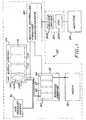
- FIG. 1set forth therein is a schematic block diagram of a printer/plotter 50 in which the invention can be employed.
- a scanning print carriage 52holds a plurality of print cartridges 60-66 which are fluidically coupled to an ink supply station 100 that supplies pressurized ink to the print cartridges 60-66.
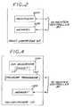
- each of the print cartridges 60-66comprises an ink jet printhead and an integral printhead memory, as schematically depicted in FIG. 2 for the representative example of the print cartridge 60 which includes an ink jet printhead 60A and an integral printhead memory 60B.
- Each print cartridgehas a fluidic regulator valve that opens and closes to maintain a slight negative gauge pressure in the cartridge that is optimal for printhead performance.
- the ink provided to each of the print cartridges 60-66is pressurized to reduce the effects of dynamic pressure drops.
- the ink supply station 100contains receptacles or bays for accepting ink containers 110-116 which are respectively associated with and fluidically connected to respective print cartridges 60-66.
- Each of the ink containers 110-114includes a collapsible ink reservoir, such as collapsible ink reservoir 110A that is surrounded by an air pressure chamber 110B.
- An air pressure source or pump 70is in communication with the air pressure chamber for pressurizing the collapsible ink reservoir.
- one pressure pumpsupplies pressurized air for all ink containers in the system.
- Pressurized inkis delivered to the print cartridges by an ink flow path that includes for example respective flexible plastic tubes connected between the ink containers 110-116 and respectively associated print cartridges 60-66.
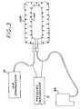
- FIG. 3is a simplified diagrammatic view illustrating the pressure source 70, an air pressure line 72 that delivers pressurizing gas to the pressure chamber 110B which pressurizes the collapsible ink reservoir 110a so as to cause ink to be delivered to the printhead cartridge via an ink supply line 74.
- a pressure transducer 71is provided for detecting a pressure differential between air that is pressurizing the collapsible ink reservoir 110a and a pressure indicative of pressure in the collapsible ink reservoir 110a.
- the pressure transducer 71is in communication with the ink supply line 74 and the air pressure line 72.
- the pressure transducer 71is disposed in the pressure chamber 110B, as illustrated in FIGS.
- the pressure transducer 71is an absolute pressure sensor that senses absolute pressure of ink in the ink supply line 74 or in the collapsible ink reservoir 110a.
- Each of the ink containersincludes a collapsible ink reservoir, an optional integral ink cartridge memory, and a collapse controlling insert in the collapsible ink reservoir that allows the collapsible ink reservoir to deformably resist collapse, as schematically depicted in FIG. 4 for the representative example of the ink container 110 that more particularly includes an ink reservoir 110A, an integral ink cartridge memory 110D, an optional pressure transducer 110C and a collapse controlling insert 115.
- the scanning print carriage 52, the print cartridges 60-66, and the ink containers 110-114are electrically interconnected to a printer microprocessor controller 80 that includes printer electronics and firmware for the control of various printer functions, including for example analog-to-digital converter circuitry for converting the outputs of the ink level sensing pressure transducers 71 associated with the ink containers 110-116.
- the controller 80thus controls the scan carriage drive system and the printheads on the print carriage to selectively energize the printheads, to cause ink droplets to be ejected in a controlled fashion on the print medium 40.
- the printer controller 80further detects a low level of remaining ink volume in each of the ink containers 110-114 pursuant to the output of the associated pressure transducer 71.
- a host processor 82which includes a CPU 82A and a software printer driver 82B, is connected to the printer controller 82.
- the host processor 82comprises a personal computer that is external to the printer 50.
- a monitor 84is connected to the host processor 82 and is used to display various messages that are indicative of the state of the ink jet printer.
- the printercan be configured for stand-alone or networked operation wherein messages are displayed on a front panel of the printer.
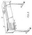
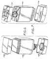
- FIG. 5shows in isometric view an exemplary form of a large format printer/plotter in which the invention can be employed, wherein four off-carriage (or off-axis) ink containers 110, 112, 114, 116 are shown installed in an ink supply station.
- the printer/plotter of FIG. 5further includes a housing 54, a front control panel 56 which provides user control switches, and a media output slot 58. While this exemplary printer/plotter is fed from a media roll, it should be appreciated that alternative sheet feed mechanisms can also be used.
- FIGS. 6-9, 10A, 10B and 11-15schematically illustrated therein is a specific implementation of an ink container 200 which employs a collapse controlling insert 115 in accordance with the invention that provides for deforming resistance to collapse of a collapsible ink reservoir, and which can be implemented as each of the ink containers 110-116 that are structurally substantially identical.
- the ink container 200generally includes an outer container or pressure vessel 1102, a chassis member 1120 attached to a neck region 1102A at a leading end of the pressure vessel 1102, a leading end cap 1104 attached to the leading end of the pressure vessel, and a trailing end cap 1106 attached to the trailing end of the pressure vessel 1102.
- the ink container 200further includes a collapsible ink bag or reservoir 114 disposed in an interior chamber 1103 defined by the pressure vessel 1102 and sealingly attached to a keel portion 1292 of the chassis 1120 which seals the interior of the pressure vessel 1102 from outside atmosphere while providing for an air inlet 1108 to the interior of the pressure vessel 1102, and an ink outlet port 1110 for ink contained in the ink reservoir 114.
- a collapse resisting or controlling insert 115is disposed in the collapsible reservoir 114 to control the differential pressure versus ink level characteristic of the ink delivery system.
- the collapse controlling insert 115allows the collapsible reservoir 114 to deformably resist collapse when the reservoir 114 has collapsed to the state where the collapsible reservoir walls are pressing against the insert 115.
- the collapsible ink reservoir 114 and the insert 115 disposed thereineffectively act like a spring that deformably resists the external pressure on the collapsible ink reservoir.
- the collapse resisting insertconfigures an ink supply pressure versus remaining characteristic of the collapsible ink reservoir so that remaining ink is reliably detected at a remaining ink level that is greater than a level that would be reliably detected without the insert. In this manner, remaining ink level is reliably detected earlier in the ink supply life, so that a low ink supply condition is detected before the ink supply is critically low.
- the insert 115can comprise a compliant element that deforms as the collapsible ink reservoir collapses, or it can be a non-compliant element that causes the collapsible ink reservoir to deformably resist the external pressure as it collapses to conform to the shape of the insert.
- the collapsible bagcan also deform as it collapses against a compliant insert.
- the collapse controlling insertcomprises a foam panel 115a, a foam panel 115b having diamond shaped cut-outs, or a foam panel 115c having rectangular cut-outs, all as shown in FIG. 10A, and which can comprise polyurethane.
- the cut-outsfacilitate more complete drainage of ink from the collapsible ink reservoir 114.
- the collapse controlling insertcomprises a compliant or non-compliant three-dimensional formed sheet, such as a wave-shaped element 115d or a C-shaped element 115e as shown in FIG. 10B.
- a compliant three-dimensional formed sheetacts like a three-dimensional spring, while a non-compliant three-dimensional formed sheet causes the stiffness of the collapsible ink reservoir to deformably resist the external pressure on the collapsible ink reservoir.
- the three-dimensional formed sheetcan made of a plastic such as polyethylene or polypropylene, or very thin stainless steel, for example.
- the chassis 1120is secured to the opening of the neck region 1102A of the pressure vessel 1102, for example by an annular crimp ring 1280 that engages a top flange of the pressure vessel and an abutting flange of the chassis member.
- a pressure sealing O-ring 1152suitably captured in a circumferential groove on the chassis 1120 engages the inside surface of the neck region 1102A of the pressure vessel 1102.
- the collapsible ink reservoir 114more particularly comprises a pleated bag having opposing walls or sides 1114, 1116.
- an elongated sheet of bag materialis folded such that opposed lateral edges of the sheet overlap or are brought together, forming an elongated cylinder.
- the lateral edgesare sealed together, and pleats are in the resulting structure generally in alignment with the seal of the lateral edges.
- the bottom or non-feed end of the bagis formed by heat sealing the pleated structure along a seam transverse to the seal of the lateral edges.
- the top or feed end of the ink reservoiris formed similarly while leaving an opening for the bag to be sealingly attached to the keel portion 1292 of the chassis 1120.
- the ink reservoir bagis sealingly attached to keel portion 1292 by heat staking.
- the collapsible ink reservoir 114thus defines an occupied portion 1103a of the interior chamber 1103, such that an unoccupied portion 1103b of the interior chamber 1103 is formed between the pressure vessel 1102 and the collapsible ink reservoir 114.
- the air inlet 1108is the only flow path into or out of the unoccupied portion 1103b which functions as an air pressure chamber, and more particularly comprises a fluid conveying conduit that is in communication with the unoccupied portion 1103b of the interior chamber 1103.
- the ink outlet port 1110is the only flow path into or out of the occupied portion 1103a and comprises a fluid conveying conduit that is in communication with the occupied portion 1103a of the interior chamber 1103, namely the interior of the collapsible ink reservoir 114.
- the ink outlet port 1110is conveniently integrated with the keel portion 1292 of the chassis 1120.
- the pressure transducer 71can be disposed in the interior chamber 1103 so as to detect a difference between a pressure of the unoccupied portion 1103b of the interior chamber 1103 and a pressure of ink in the collapsible ink reservoir 114 (i.e., a differential pressure), or an absolute pressure of ink in the collapsible ink reservoir 114.
- the pressure transducer 71is mounted on a ceramic substrate 73 to form a transducer subassembly that is attached to an outside wall of the output port 1110.
- a bore or opening in the wall of the output port 1110 and a bore or opening in the substrate 73expose the pressure transducer to pressure in the output port 1110.
- Appropriate sealing including an O-ring 75is provided to prevent leakage between the interior of the outlet port 1110 and the unoccupied portion 1103b of the interior chamber 1103.
- the pressure transducer 71is very close to the ink supply in the collapsible ink reservoir 114 so as to avoid dynamic losses between the ink supply and the point of pressure measurement, and thus the pressure transducer 71 is effectively exposed to the pressure in the collapsible ink reservoir 114.
- the electrical output of the pressure transducer 71is provided to externally accessible contact pads 81 disposed on the top of the chassis 1120 via conductive leads 83 of a flexible printed circuit substrate 85 that extends between the ceramic substrate and the top of the chassis 1120, passing on the outside surface of the chassis 1120 between the O-ring 1152 and such outside surface.
- the conductive leads 83are electrically connected to the externally accessible contact pads 81 disposed on the top of the chassis which can be formed on one end of the flexible printed circuit substrate 85 that would be attached to the top of the chassis 1120.
- the output of the pressure transducer 71can be sampled while printing which avoids the need to interrupt printing to take a reading.
- a memory chip package 87can be conveniently mounted on the ceramic substrate 87 and interconnected to associated externally accessible contact pads by associated conductive leads 83 of the flexible printed circuit substrate 85.
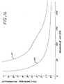
- FIG. 16sets forth a schematic representative ink supply differential pressure versus remaining ink characteristic 101 for a system that employs a collapsible ink bag having a collapse controlling compliant foam insert in accordance with the invention, and a schematic representative ink supply differential pressure versus remaining ink characteristic 102 for a system that employs the same or similar collapsible ink bag but without a compliant foam insert.
- FIG. 16sets forth a schematic representative ink supply differential pressure versus remaining ink characteristic 101 for a system that employs a collapsible ink bag having a collapse controlling compliant foam insert in accordance with the invention, and a schematic representative ink supply differential pressure versus remaining ink characteristic 102 for a system that employs the same or similar collapsible ink bag but without a compliant foam insert.
- 17sets forth a schematic representative ink supply differential pressure versus remaining ink characteristic 101a for a system that employs a collapsible ink bag having a rigid wave-shaped insert in accordance with the invention, and a schematic representative ink supply differential pressure versus remaining ink characteristic 102a for a system that employs the same or similar collapsible ink bag but without a rigid wave-shaped collapse controlling insert.
- the pressure of the ink supply(for example as detected via the ink supply line) remains approximately equal to the pressure of the pressurizing gas (for example in the pressure line) for much of the ink supply life, and thus the differential pressure is approximately zero for much of the ink supply life.
- the pressure of the ink supplydecreases with decreasing remaining ink, whereby the differential pressure increases with decreasing ink.
- the insertcauses the ink supply differential pressure to start to increase at a remaining ink level that is greater than the level at which the ink supply differential pressure would start to increase without an insert, which can used to detect an impending low ink level condition when the remaining ink is not yet critically low, which in turn can be used to provide an earlier warning to the user that allows for convenient replacement of the ink container.
- the insertallows for reliable detection of ink level earlier in the ink supply life, and thus increases the ink level range over which a low ink level threshold can be selected, wherein a low ink level warning is provided when the ink level decreases below such low ink level threshold as indicated by the differential pressure signal increasing above a selected pressure threshold.
- the usercan print additional output before replacing the ink container.
- the relationship between differential pressure and the amount of ink remainingis reasonably consistent for any given system and can be reliably characterized, and the insert is configured to select the onset of a reliable pressure signal.
- the inserteffectively provides for control of the ink supply pressure versus remaining ink characteristic wherein supply pressure would decrease when it starts to change, and that a low ink level warning is provided when the supply pressure decreases below a selected supply pressure threshold that is indicative of a low ink level threshold.
- the insertincreases the ink level range over which a low ink level threshold can be selected, wherein a low ink level warning is provided when the ink level decreases below such low ink level threshold as indicated by the supply pressure decreasing below a selected supply pressure threshold.
- the inventioncan be employed in systems wherein the ink supply is subjected only to ambient or atmospheric pressure instead of a pressure that is greater than atmospheric pressure, for example in a system wherein a non-pressurized ink supply is elevated so that ink flows out of the ink container by gravity.
- the disclosed inventioncan be employed in other printing or marking systems that employ liquid ink such as liquid electrophotographic printing systems.
Landscapes
- Ink Jet (AREA)
Description
- The invention relates to an ink container according to the preamble of claim 1, (US-A-6,053,607).
- The art of ink jet printing is relatively well developed. Commercial products such as computer printers, graphics plotters, and facsimile machines have been implemented with ink jet technology for producing printed media. Generally, an ink jet image is formed pursuant to precise placement on a print medium of ink drops emitted by an ink drop generating device known as an ink jet printhead. Typically, an ink jet printhead is supported on a movable carriage that traverses over the surface of the print medium and is controlled to eject drops of ink at appropriate times pursuant to command of a microcomputer or other controller, wherein the timing of the application of the ink drops is intended to correspond to a pattern of pixels of the image being printed.
- Some known printers make use of an ink container that is separably replaceable from the printhead. When the ink container is exhausted it is removed and replaced with a new ink container. The use of replaceable ink containers that are separate from the printhead allow users to replace the ink container without replacing the printhead. The printhead is then replaced at or near the end of printhead life, and not when the ink container is replaced.
- A consideration with ink jet printing systems that employ ink containers that are separate from the printheads is the general inability to predict an out of ink condition for an ink container. In such ink jet printing systems, it is important that printing cease when an ink container is nearly empty with a small amount of stranded ink. Otherwise, printhead damage may occur as a result of firing without ink, and/or time is wasted in operating a printer without achieving a complete printed image, which is particularly time consuming in the printing of large images which often are printed in an unattended manner on expensive media.
- The problem to be solved by the invention is to provide an ink container of the kind as defined in the preamble of claim 1 offering the ability to predict an out of ink condition and to provide for cease of printing when the ink container is nearly empty.
- This problem is solved by claim 1.
- The advantages and features of the disclosed invention will readily be appreciated by persons skilled in the art from the following detailed description when read in conjunction with the drawing wherein:
- FIG. 1 is a schematic block diagram of a printer/plotter system in which an ink level sensing circuit in accordance with the invention can be employed.
- FIG. 2 is a schematic block diagram depicting major components of one of the print cartridges of the printer/plotter system of FIG. 1.
- FIG. 3 is a schematic block diagram illustrating in a simplified manner the connection between an off-carriage ink container, an air pressure source, and an on-carriage print cartridge of the printer/plotter system of FIG. 1.
- FIG. 4 is a schematic block diagram depicting major components of one of the ink containers of the printer/plotter system of FIG. 1.
- FIG. 5 a simplified isometric view of an implementation of the printer/plotter system of FIG. 1.
- FIG. 6 is a schematic isometric exploded view illustrating the major components of an implementation of one of the ink containers of the printer/plotter system of FIG. 1.
- FIG. 7 is a further schematic isometric exploded view illustrating the major components of an implementation of one of the ink containers of the printer/plotter system of FIG. 1.
- FIG. 8 is an exploded isometric view showing the pressure vessel, collapsible ink reservoir, and chassis member of the ink container of FIGS. 6 and 7.
- FIG. 9 is a schematic isometric view illustrating the collapsible ink reservoir and chassis member of the ink container of FIGS. 6 and 7.
- FIG. 10A schematically illustrates exemplary inserts of the ink container of FIGS. 6 and 7.
- FIG. 10B schematically illustrates further exemplary inserts of the ink container of FIGS. 6 and 7.
- FIG. 11 is a cross-sectional view of a pressure transducer disposed in the ink container of FIGS. 6 and 7.
- FIG. 12 is a cross sectional view illustrating the attachment of the pressure transducer to the chassis member of the ink container of FIGS. 6 and 7.
- FIG. 13 is an isometric view illustrating electrical contacts disposed on the top portion of the chassis member of the ink container of FIGS. 6 and 7.
- FIG. 14 is an isometric view illustrating the attachment of the pressure transducer to the chassis member of the ink container of FIGS. 6 and 7.
- FIG. 15 is an exploded view illustrating the pressure transducer and the chassis member of the ink container of FIGS. 6 and 7.
- FIG. 16 is a graph of a schematic representative differential pressure versus remaining ink characteristic for a system that employs a collapsible ink reservoir having a compliant insert in accordance with the invention, and a schematic representative differential pressure versus remaining ink characteristic for a system that employs the same or similar collapsible ink reservoir but without a compliant insert.
- FIG. 17 is a graph of a schematic representative differential pressure versus remaining ink characteristic for a system that employs a collapsible ink reservoir having an inflexible insert in accordance with the invention, and a schematic representative differential pressure versus remaining ink characteristic for a system that employs the same or similar collapsible ink reservoir but without an inflexible insert.
- In the following detailed description and in the several figures of the drawing, like elements are identified with like reference numerals.
- Referring now to FIG. 1, set forth therein is a schematic block diagram of a printer/
plotter 50 in which the invention can be employed. Ascanning print carriage 52 holds a plurality of print cartridges 60-66 which are fluidically coupled to anink supply station 100 that supplies pressurized ink to the print cartridges 60-66. By way of illustrative example, each of the print cartridges 60-66 comprises an ink jet printhead and an integral printhead memory, as schematically depicted in FIG. 2 for the representative example of theprint cartridge 60 which includes anink jet printhead 60A and an integral printhead memory 60B. Each print cartridge has a fluidic regulator valve that opens and closes to maintain a slight negative gauge pressure in the cartridge that is optimal for printhead performance. The ink provided to each of the print cartridges 60-66 is pressurized to reduce the effects of dynamic pressure drops. - The
ink supply station 100 contains receptacles or bays for accepting ink containers 110-116 which are respectively associated with and fluidically connected to respective print cartridges 60-66. Each of the ink containers 110-114 includes a collapsible ink reservoir, such ascollapsible ink reservoir 110A that is surrounded by anair pressure chamber 110B. An air pressure source orpump 70 is in communication with the air pressure chamber for pressurizing the collapsible ink reservoir. For example, one pressure pump supplies pressurized air for all ink containers in the system. Pressurized ink is delivered to the print cartridges by an ink flow path that includes for example respective flexible plastic tubes connected between the ink containers 110-116 and respectively associated print cartridges 60-66. - FIG. 3 is a simplified diagrammatic view illustrating the
pressure source 70, an air pressure line 72 that delivers pressurizing gas to thepressure chamber 110B which pressurizes the collapsible ink reservoir 110a so as to cause ink to be delivered to the printhead cartridge via an ink supply line 74. Apressure transducer 71 is provided for detecting a pressure differential between air that is pressurizing the collapsible ink reservoir 110a and a pressure indicative of pressure in the collapsible ink reservoir 110a. For example, thepressure transducer 71 is in communication with the ink supply line 74 and the air pressure line 72. Alternatively, thepressure transducer 71 is disposed in thepressure chamber 110B, as illustrated in FIGS. 11-15, and senses an ink pressure in the collapsible ink reservoir 110a and a pressure in thepressure chamber 110B. As a further alternative, thepressure transducer 71 is an absolute pressure sensor that senses absolute pressure of ink in the ink supply line 74 or in the collapsible ink reservoir 110a. - Each of the ink containers includes a collapsible ink reservoir, an optional integral ink cartridge memory, and a collapse controlling insert in the collapsible ink reservoir that allows the collapsible ink reservoir to deformably resist collapse, as schematically depicted in FIG. 4 for the representative example of the
ink container 110 that more particularly includes anink reservoir 110A, an integralink cartridge memory 110D, an optional pressure transducer 110C and acollapse controlling insert 115. - Continuing to refer to FIG. 1, the
scanning print carriage 52, the print cartridges 60-66, and the ink containers 110-114 are electrically interconnected to aprinter microprocessor controller 80 that includes printer electronics and firmware for the control of various printer functions, including for example analog-to-digital converter circuitry for converting the outputs of the ink levelsensing pressure transducers 71 associated with the ink containers 110-116. Thecontroller 80 thus controls the scan carriage drive system and the printheads on the print carriage to selectively energize the printheads, to cause ink droplets to be ejected in a controlled fashion on the print medium 40. Theprinter controller 80 further detects a low level of remaining ink volume in each of the ink containers 110-114 pursuant to the output of the associatedpressure transducer 71. - A
host processor 82, which includes aCPU 82A and a software printer driver 82B, is connected to theprinter controller 82. For example, thehost processor 82 comprises a personal computer that is external to theprinter 50. Amonitor 84 is connected to thehost processor 82 and is used to display various messages that are indicative of the state of the ink jet printer. Alternatively, the printer can be configured for stand-alone or networked operation wherein messages are displayed on a front panel of the printer. - FIG. 5 shows in isometric view an exemplary form of a large format printer/plotter in which the invention can be employed, wherein four off-carriage (or off-axis)
ink containers housing 54, afront control panel 56 which provides user control switches, and amedia output slot 58. While this exemplary printer/plotter is fed from a media roll, it should be appreciated that alternative sheet feed mechanisms can also be used. - Referring now to FIGS. 6-9, 10A, 10B and 11-15, schematically illustrated therein is a specific implementation of an
ink container 200 which employs acollapse controlling insert 115 in accordance with the invention that provides for deforming resistance to collapse of a collapsible ink reservoir, and which can be implemented as each of the ink containers 110-116 that are structurally substantially identical. - As shown in FIGS. 6-7, the
ink container 200 generally includes an outer container orpressure vessel 1102, achassis member 1120 attached to aneck region 1102A at a leading end of thepressure vessel 1102, a leadingend cap 1104 attached to the leading end of the pressure vessel, and atrailing end cap 1106 attached to the trailing end of thepressure vessel 1102. - As more particularly shown in FIGS. 8-9 and 11, the
ink container 200 further includes a collapsible ink bag orreservoir 114 disposed in aninterior chamber 1103 defined by thepressure vessel 1102 and sealingly attached to a keel portion 1292 of thechassis 1120 which seals the interior of thepressure vessel 1102 from outside atmosphere while providing for anair inlet 1108 to the interior of thepressure vessel 1102, and anink outlet port 1110 for ink contained in theink reservoir 114. In accordance with the invention, a collapse resisting or controllinginsert 115 is disposed in thecollapsible reservoir 114 to control the differential pressure versus ink level characteristic of the ink delivery system. - More particularly, the
collapse controlling insert 115 allows thecollapsible reservoir 114 to deformably resist collapse when thereservoir 114 has collapsed to the state where the collapsible reservoir walls are pressing against theinsert 115. Thecollapsible ink reservoir 114 and theinsert 115 disposed therein effectively act like a spring that deformably resists the external pressure on the collapsible ink reservoir. - When the
collapsible reservoir 114 is resisting collapse, the difference between the pressure outside thecollapsible ink reservoir 114 and the pressure inside thecollapsible ink reservoir 114 starts to increase at a remaining ink level that is greater than the remaining ink level at which such difference would start to increase without the insert. In other words, the collapse resisting insert configures an ink supply pressure versus remaining characteristic of the collapsible ink reservoir so that remaining ink is reliably detected at a remaining ink level that is greater than a level that would be reliably detected without the insert. In this manner, remaining ink level is reliably detected earlier in the ink supply life, so that a low ink supply condition is detected before the ink supply is critically low. - The
insert 115 can comprise a compliant element that deforms as the collapsible ink reservoir collapses, or it can be a non-compliant element that causes the collapsible ink reservoir to deformably resist the external pressure as it collapses to conform to the shape of the insert. Depending upon the deformability of a compliant insert, the collapsible bag can also deform as it collapses against a compliant insert. - By way of illustrative examples, the collapse controlling insert comprises a foam panel 115a, a foam panel 115b having diamond shaped cut-outs, or a foam panel 115c having rectangular cut-outs, all as shown in FIG. 10A, and which can comprise polyurethane. The cut-outs facilitate more complete drainage of ink from the
collapsible ink reservoir 114. - By way of further illustrative examples, the collapse controlling insert comprises a compliant or non-compliant three-dimensional formed sheet, such as a wave-shaped element 115d or a C-shaped element 115e as shown in FIG. 10B. A compliant three-dimensional formed sheet acts like a three-dimensional spring, while a non-compliant three-dimensional formed sheet causes the stiffness of the collapsible ink reservoir to deformably resist the external pressure on the collapsible ink reservoir. The three-dimensional formed sheet can made of a plastic such as polyethylene or polypropylene, or very thin stainless steel, for example.
- The
chassis 1120 is secured to the opening of theneck region 1102A of thepressure vessel 1102, for example by anannular crimp ring 1280 that engages a top flange of the pressure vessel and an abutting flange of the chassis member. A pressure sealing O-ring 1152 suitably captured in a circumferential groove on thechassis 1120 engages the inside surface of theneck region 1102A of thepressure vessel 1102. - The
collapsible ink reservoir 114 more particularly comprises a pleated bag having opposing walls orsides chassis 1120. By way of specific example, the ink reservoir bag is sealingly attached to keel portion 1292 by heat staking. - The
collapsible ink reservoir 114 thus defines an occupied portion 1103a of theinterior chamber 1103, such that an unoccupied portion 1103b of theinterior chamber 1103 is formed between thepressure vessel 1102 and thecollapsible ink reservoir 114. Theair inlet 1108 is the only flow path into or out of the unoccupied portion 1103b which functions as an air pressure chamber, and more particularly comprises a fluid conveying conduit that is in communication with the unoccupied portion 1103b of theinterior chamber 1103. Theink outlet port 1110 is the only flow path into or out of the occupied portion 1103a and comprises a fluid conveying conduit that is in communication with the occupied portion 1103a of theinterior chamber 1103, namely the interior of thecollapsible ink reservoir 114. Theink outlet port 1110 is conveniently integrated with the keel portion 1292 of thechassis 1120. - As more specifically shown in FIGS. 11-15, the
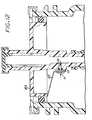
pressure transducer 71 can be disposed in theinterior chamber 1103 so as to detect a difference between a pressure of the unoccupied portion 1103b of theinterior chamber 1103 and a pressure of ink in the collapsible ink reservoir 114 (i.e., a differential pressure), or an absolute pressure of ink in thecollapsible ink reservoir 114. By way of illustrative example, thepressure transducer 71 is mounted on aceramic substrate 73 to form a transducer subassembly that is attached to an outside wall of theoutput port 1110. A bore or opening in the wall of theoutput port 1110 and a bore or opening in thesubstrate 73 expose the pressure transducer to pressure in theoutput port 1110. Appropriate sealing including an O-ring 75 is provided to prevent leakage between the interior of theoutlet port 1110 and the unoccupied portion 1103b of theinterior chamber 1103. Thepressure transducer 71 is very close to the ink supply in thecollapsible ink reservoir 114 so as to avoid dynamic losses between the ink supply and the point of pressure measurement, and thus thepressure transducer 71 is effectively exposed to the pressure in thecollapsible ink reservoir 114. - The electrical output of the
pressure transducer 71 is provided to externallyaccessible contact pads 81 disposed on the top of thechassis 1120 via conductive leads 83 of a flexible printedcircuit substrate 85 that extends between the ceramic substrate and the top of thechassis 1120, passing on the outside surface of thechassis 1120 between the O-ring 1152 and such outside surface. The conductive leads 83 are electrically connected to the externallyaccessible contact pads 81 disposed on the top of the chassis which can be formed on one end of the flexible printedcircuit substrate 85 that would be attached to the top of thechassis 1120. The output of thepressure transducer 71 can be sampled while printing which avoids the need to interrupt printing to take a reading. - Optionally, a memory chip package 87 can be conveniently mounted on the ceramic substrate 87 and interconnected to associated externally accessible contact pads by associated conductive leads 83 of the flexible printed
circuit substrate 85. - In regard to detecting a low ink level, the control of the pressure versus remaining ink characteristic provided by use of the
collapse controlling insert 115 can be more particularly understood by reference to FIGS. 16 and 17. FIG. 16 sets forth a schematic representative ink supply differential pressure versus remainingink characteristic 101 for a system that employs a collapsible ink bag having a collapse controlling compliant foam insert in accordance with the invention, and a schematic representative ink supply differential pressure versus remaining ink characteristic 102 for a system that employs the same or similar collapsible ink bag but without a compliant foam insert. FIG. 17 sets forth a schematic representative ink supply differential pressure versus remaining ink characteristic 101a for a system that employs a collapsible ink bag having a rigid wave-shaped insert in accordance with the invention, and a schematic representative ink supply differential pressure versus remaining ink characteristic 102a for a system that employs the same or similar collapsible ink bag but without a rigid wave-shaped collapse controlling insert. - The pressure of the ink supply (for example as detected via the ink supply line) remains approximately equal to the pressure of the pressurizing gas (for example in the pressure line) for much of the ink supply life, and thus the differential pressure is approximately zero for much of the ink supply life. As the ink supply approaches an empty condition, the pressure of the ink supply decreases with decreasing remaining ink, whereby the differential pressure increases with decreasing ink. Use of the insert causes the ink supply differential pressure to start to increase at a remaining ink level that is greater than the level at which the ink supply differential pressure would start to increase without an insert, which can used to detect an impending low ink level condition when the remaining ink is not yet critically low, which in turn can be used to provide an earlier warning to the user that allows for convenient replacement of the ink container. In other words, the insert allows for reliable detection of ink level earlier in the ink supply life, and thus increases the ink level range over which a low ink level threshold can be selected, wherein a low ink level warning is provided when the ink level decreases below such low ink level threshold as indicated by the differential pressure signal increasing above a selected pressure threshold. For example, if the low ink level is selected to be earlier in the life of the ink supply, the user can print additional output before replacing the ink container. The relationship between differential pressure and the amount of ink remaining is reasonably consistent for any given system and can be reliably characterized, and the insert is configured to select the onset of a reliable pressure signal.
- It should be appreciated that the insert effectively provides for control of the ink supply pressure versus remaining ink characteristic wherein supply pressure would decrease when it starts to change, and that a low ink level warning is provided when the supply pressure decreases below a selected supply pressure threshold that is indicative of a low ink level threshold. The insert increases the ink level range over which a low ink level threshold can be selected, wherein a low ink level warning is provided when the ink level decreases below such low ink level threshold as indicated by the supply pressure decreasing below a selected supply pressure threshold.
- While the foregoing implementation applies greater than ambient pressure to the ink supply, the invention can be employed in systems wherein the ink supply is subjected only to ambient or atmospheric pressure instead of a pressure that is greater than atmospheric pressure, for example in a system wherein a non-pressurized ink supply is elevated so that ink flows out of the ink container by gravity. Also, the disclosed invention can be employed in other printing or marking systems that employ liquid ink such as liquid electrophotographic printing systems.
Claims (5)
- An ink container comprising
a collapsible ink reservoir (114) for containing a supply of ink;
an outer container (1102) for enclosing said collapsible ink reservoir; and
an insert structure (115a-115e) disposed in said collapsible ink reservoir for allowing said collapsible ink reservoir to resist collapse of said collapsible ink reservoir, whereby resistance to collapse controls a pressure versus remaining ink characteristics of said collapsible ink reservoir,characterized in that
said insert structure (115d;115e) constitutes a volume which is smaller than the volume of the collapsible ink reservoir (114) such that the insert resists further collapse of the ink reservoir when the reservoir has collapsed to a state where the reservoir walls are in pressing contact with the insert. - The ink container of claim 1, wherein said insert (115a-115e) determines an amount of remaining ink at which said pressure starts to change.
- The ink container of claim 1 or 2, wherein said pressure starts to change at an amount of remaining ink that is greater than an amount of remaining ink at which said pressure would change if said collapsible ink reservoir (114) did not include said insert (115a-115e).
- The ink container of one of the preceding claims further including a pressure transducer (71) located inside said outer container (1102) for sensing a pressure of said supply of ink
- The ink container of one of the preceding claims, wherein the insert is a three dimensionally formel sheet.
Applications Claiming Priority (2)
| Application Number | Priority Date | Filing Date | Title |
|---|---|---|---|
| US09/698,899US6644794B1 (en) | 2000-10-27 | 2000-10-27 | Collapsible ink reservoir with a collapse resisting insert |
| US698899 | 2003-10-31 |
Publications (2)
| Publication Number | Publication Date |
|---|---|
| EP1203666A1 EP1203666A1 (en) | 2002-05-08 |
| EP1203666B1true EP1203666B1 (en) | 2006-06-14 |
Family
ID=24807114
Family Applications (1)
| Application Number | Title | Priority Date | Filing Date |
|---|---|---|---|
| EP01116867AExpired - LifetimeEP1203666B1 (en) | 2000-10-27 | 2001-07-10 | Pressure-based Ink level sense enhancement using a pressure controlling element in an Ink bag |
Country Status (4)
| Country | Link |
|---|---|
| US (2) | US6644794B1 (en) |
| EP (1) | EP1203666B1 (en) |
| JP (1) | JP2002160385A (en) |
| DE (1) | DE60120599T2 (en) |
Cited By (1)
| Publication number | Priority date | Publication date | Assignee | Title |
|---|---|---|---|---|
| US10226937B2 (en) | 2007-10-12 | 2019-03-12 | Videojet Technologies Inc. | Container and method for liquid storage and dispensing |
Families Citing this family (28)
| Publication number | Priority date | Publication date | Assignee | Title |
|---|---|---|---|---|
| DE19906826B4 (en)* | 1998-09-01 | 2005-01-27 | Hewlett-Packard Co. (N.D.Ges.D.Staates Delaware), Palo Alto | Pressure-based ink level detector and method for detecting an ink level |
| US6644794B1 (en)* | 2000-10-27 | 2003-11-11 | Hewlett-Packard Development Company, L.P. | Collapsible ink reservoir with a collapse resisting insert |
| US6648434B2 (en) | 2001-03-08 | 2003-11-18 | Hewlett-Packard Development Company, L.P. | Digitally compensated pressure ink level sense system and method |
| US6644797B2 (en)* | 2002-01-18 | 2003-11-11 | Hewlett-Packard Development Company, L.P. | Filter for an ink jet pen |
| US6811249B2 (en) | 2002-10-30 | 2004-11-02 | Hewlett-Packard Development Company, L.P. | Method and apparatus for determining a minimum pressure to print |
| CA2461959C (en)* | 2003-03-26 | 2012-07-24 | Seiko Epson Corporation | Liquid container |
| JP4165278B2 (en) | 2003-04-09 | 2008-10-15 | ブラザー工業株式会社 | Ink jet recording apparatus and ink cartridge |
| JP4529369B2 (en)* | 2003-04-16 | 2010-08-25 | ブラザー工業株式会社 | Inkjet recording device |
| US7377626B2 (en)* | 2004-07-09 | 2008-05-27 | Nukote International, Inc. | External ink supply bag and method of filling the same |
| US20060007278A1 (en)* | 2004-07-09 | 2006-01-12 | Nu-Kote International, Inc., A Corporation Of Delaware | Ink delivery system for the continuous refill of ink jet cartridges |
| JP2006035484A (en) | 2004-07-23 | 2006-02-09 | Seiko Epson Corp | Liquid container and method for detecting remaining quantity of liquid |
| WO2006012897A1 (en)* | 2004-08-06 | 2006-02-09 | Enilorak Aps | Ink refill system |
| US20070139489A1 (en)* | 2005-12-19 | 2007-06-21 | Wang Alex K | Refilling device of an ink cartridge for an inkjet printer |
| US20080129810A1 (en)* | 2006-12-01 | 2008-06-05 | Illinois Tool Works, Inc. | Compliant chamber with check valve and internal energy absorbing element for inkjet printhead |
| JP5248816B2 (en)* | 2007-07-25 | 2013-07-31 | 富士フイルム株式会社 | Liquid ejecting apparatus and image forming apparatus |
| US9067425B2 (en) | 2007-10-12 | 2015-06-30 | Videojet Technologies Inc. | Fluid cartridge for an inkjet printer |
| US20090153600A1 (en)* | 2007-12-17 | 2009-06-18 | Greeven John C | System and method for detecting fluid ejection volume |
| MX347337B (en) | 2011-10-24 | 2017-04-24 | Hewlett Packard Development Co Lp | Inkjet printhead device, fluid ejection device, and method thereof. |
| US9261209B2 (en)* | 2012-04-18 | 2016-02-16 | Hewlett-Packard Development Company, L.P. | Fluid coupling |
| WO2015119594A1 (en)* | 2014-02-04 | 2015-08-13 | Hewlett-Packard Development Company, L.P. | Sensor assemblies to identify ink levels |
| CN104742528B (en)* | 2015-04-22 | 2016-09-07 | 京东方科技集团股份有限公司 | A kind of printing device |
| EP3651993A1 (en)* | 2017-07-12 | 2020-05-20 | Hewlett-Packard Development Company, L.P. | Determining an out-of-liquid condition |
| US11235582B2 (en) | 2017-09-25 | 2022-02-01 | Hewlett-Packard Development Company, L.P. | Detecting ink states for printers based on monitored differential pressures |
| US11230112B2 (en) | 2018-01-25 | 2022-01-25 | Hewlett-Packard Development Company, L.P. | Fluid supply levels based on fluid supply depressurizations |
| CN110871628B (en)* | 2018-08-31 | 2022-05-27 | 鸿富锦精密工业(深圳)有限公司 | Ink cartridge |
| US12011931B2 (en) | 2019-12-11 | 2024-06-18 | Hewlett-Packard Development Company, L.P. | Refill system and method |
| US20230202188A1 (en)* | 2020-04-20 | 2023-06-29 | Hewlett-Packard Development Company, L.P. | Fill state monitorization of a fluid supply system |
| US12325239B2 (en) | 2021-02-05 | 2025-06-10 | Hewlett-Packard Development Company, L.P. | Printing fluid pressure determination |
Family Cites Families (31)
| Publication number | Priority date | Publication date | Assignee | Title |
|---|---|---|---|---|
| US4038650A (en) | 1975-10-14 | 1977-07-26 | Martin Evans | Fluid level detector and probe assembly |
| JPS5573564A (en) | 1978-11-29 | 1980-06-03 | Ricoh Co Ltd | Ink feed system of ink jet printer |
| US4544840A (en) | 1979-08-31 | 1985-10-01 | The Johns Hopkins University | Fiber optic fluid impurity detector |
| US4558326A (en)* | 1982-09-07 | 1985-12-10 | Konishiroku Photo Industry Co., Ltd. | Purging system for ink jet recording apparatus |
| US4604633A (en) | 1982-12-08 | 1986-08-05 | Konishiroku Photo Industry Co., Ltd | Ink-jet recording apparatus |
| JPH0671791B2 (en) | 1983-07-20 | 1994-09-14 | キヤノン株式会社 | How to detect the amount of ink remaining in an ink jet printer |
| JPS6046256A (en) | 1983-08-25 | 1985-03-13 | Canon Inc | Liquid jet recorder |
| US4639738A (en) | 1985-04-12 | 1987-01-27 | Eastman Kodak Company | Ink level detection system for ink jet printing apparatus |
| DE3708865C2 (en) | 1986-03-19 | 2001-04-19 | Canon Kk | Device for determining the residual ink quantity in an inkjet printer |
| US5729256A (en) | 1987-04-15 | 1998-03-17 | Canon Kabushiki Kaisha | Ink remain detector having a biased flexible film member with limited deformation |
| EP0660092B1 (en) | 1987-04-15 | 2003-07-30 | Canon Kabushiki Kaisha | A remain detector and a liquid injection recording apparatus having the detector |
| JPH01237148A (en) | 1988-03-18 | 1989-09-21 | Canon Inc | inkjet recording device |
| JP2675851B2 (en)* | 1989-01-28 | 1997-11-12 | キヤノン株式会社 | INKJET RECORDING METHOD AND DEVICE USED FOR THE METHOD |
| DE69026983T2 (en) | 1989-06-29 | 1996-11-21 | Canon Kk | Improved ink quantity sensing device and recorder with the device |
| US4973993A (en) | 1989-07-11 | 1990-11-27 | Hewlett-Packard Company | Ink-quantity and low ink sensing for ink-jet printers |
| US5280300A (en)* | 1991-08-27 | 1994-01-18 | Hewlett-Packard Company | Method and apparatus for replenishing an ink cartridge |
| US5757406A (en)* | 1992-08-12 | 1998-05-26 | Hewlett-Packard Company | Negative pressure ink delivery system |
| IT1256844B (en) | 1992-06-08 | 1995-12-21 | Olivetti & Co Spa | METHOD AND DEVICE FOR THE RECOGNITION OF THE END-INK IN AN INK-JET PRINT HEAD. |
| CA2093981C (en)* | 1992-08-12 | 2001-03-20 | George T. Kaplinsky | Collapsible ink reservoir structure and printer ink cartridge |
| DE69315159T2 (en) | 1992-09-25 | 1998-03-12 | Hewlett Packard Co | Method and device for controlling a color jet printer by means of drop counting |
| US5448275A (en)* | 1992-12-18 | 1995-09-05 | Hewlett-Packard Company | Thermal ink jet pen having foam controlled backpressure regulation and method of manufacture and operation |
| US5650811A (en)* | 1993-05-21 | 1997-07-22 | Hewlett-Packard Company | Apparatus for providing ink to a printhead |
| US5369429A (en)* | 1993-10-20 | 1994-11-29 | Lasermaster Corporation | Continuous ink refill system for disposable ink jet cartridges having a predetermined ink capacity |
| US5583545A (en) | 1994-10-31 | 1996-12-10 | Hewlett-Packard Company | Ink level detection in a pressure regulated pen |
| US6290343B1 (en)* | 1996-07-15 | 2001-09-18 | Hewlett-Packard Company | Monitoring and controlling ink pressurization in a modular ink delivery system for an inkjet printer |
| US6036296A (en) | 1996-10-31 | 2000-03-14 | Hewlett-Packard Company | Fluid level detection apparatus and method for determining the volume of fluid in a container |
| JPH11157093A (en)* | 1997-11-28 | 1999-06-15 | Konica Corp | Ink jet printer |
| DE29801461U1 (en)* | 1998-01-29 | 1998-04-02 | Basf Ag, 67063 Ludwigshafen | Spring element, especially for ink cartridges |
| JPH11286121A (en)* | 1998-02-06 | 1999-10-19 | Canon Inc | Ink tank, ink jet print head using the ink tank, print head cartridge, and ink jet printing apparatus |
| JPH11237148A (en) | 1998-02-19 | 1999-08-31 | Hoshizaki Electric Co Ltd | Manufacture of cooling unit |
| US6644794B1 (en)* | 2000-10-27 | 2003-11-11 | Hewlett-Packard Development Company, L.P. | Collapsible ink reservoir with a collapse resisting insert |
- 2000
- 2000-10-27USUS09/698,899patent/US6644794B1/ennot_activeExpired - Lifetime
- 2001
- 2001-07-10DEDE60120599Tpatent/DE60120599T2/ennot_activeExpired - Lifetime
- 2001-07-10EPEP01116867Apatent/EP1203666B1/ennot_activeExpired - Lifetime
- 2001-10-26JPJP2001328797Apatent/JP2002160385A/enactivePending
- 2003
- 2003-09-18USUS10/666,337patent/US6988793B2/ennot_activeExpired - Lifetime
Cited By (1)
| Publication number | Priority date | Publication date | Assignee | Title |
|---|---|---|---|---|
| US10226937B2 (en) | 2007-10-12 | 2019-03-12 | Videojet Technologies Inc. | Container and method for liquid storage and dispensing |
Also Published As
| Publication number | Publication date |
|---|---|
| JP2002160385A (en) | 2002-06-04 |
| DE60120599T2 (en) | 2007-05-31 |
| EP1203666A1 (en) | 2002-05-08 |
| US6644794B1 (en) | 2003-11-11 |
| US6988793B2 (en) | 2006-01-24 |
| DE60120599D1 (en) | 2006-07-27 |
| US20040066436A1 (en) | 2004-04-08 |
Similar Documents
| Publication | Publication Date | Title |
|---|---|---|
| EP1203666B1 (en) | Pressure-based Ink level sense enhancement using a pressure controlling element in an Ink bag | |
| EP1201437B1 (en) | An ink bag fitment with an integrated pressure sensor for low ink detection | |
| US6164743A (en) | Ink container with an inductive ink level sense | |
| EP0882595B1 (en) | Ink level estimation using drop count and ink level sense | |
| EP1914079B1 (en) | Pressure sensor with shock protection in fluid container | |
| EP0986483B1 (en) | An ink container having a multiple function chassis | |
| EP0941854B1 (en) | Low cost pressurizable ink container | |
| KR970010565B1 (en) | 2-way valve device | |
| US6017118A (en) | High performance ink container with efficient construction | |
| EP2139693B1 (en) | Compact ink delivery in an ink pen | |
| KR960040664A (en) | Inkjet Printers / Plotters | |
| EP1199177B1 (en) | Ink bag and recording apparatus incorporating the same | |
| US7465040B2 (en) | Labyrinth seal structure with redundant fluid flow paths | |
| US20250050652A1 (en) | System for delivering ink to a printhead | |
| AU693894B2 (en) | Valve, liquid container using same, recording heat cartridge having liquid container and recording apparatus using liquid container |
Legal Events
| Date | Code | Title | Description |
|---|---|---|---|
| PUAI | Public reference made under article 153(3) epc to a published international application that has entered the european phase | Free format text:ORIGINAL CODE: 0009012 | |
| AK | Designated contracting states | Kind code of ref document:A1 Designated state(s):AT BE CH CY DE DK ES FI FR GB GR IE IT LI LU MC NL PT SE TR | |
| AX | Request for extension of the european patent | Free format text:AL;LT;LV;MK;RO;SI | |
| 17P | Request for examination filed | Effective date:20020705 | |
| AKX | Designation fees paid | Designated state(s):DE FR GB NL | |
| 17Q | First examination report despatched | Effective date:20040305 | |
| GRAP | Despatch of communication of intention to grant a patent | Free format text:ORIGINAL CODE: EPIDOSNIGR1 | |
| GRAS | Grant fee paid | Free format text:ORIGINAL CODE: EPIDOSNIGR3 | |
| GRAA | (expected) grant | Free format text:ORIGINAL CODE: 0009210 | |
| AK | Designated contracting states | Kind code of ref document:B1 Designated state(s):DE FR GB NL | |
| REG | Reference to a national code | Ref country code:GB Ref legal event code:FG4D | |
| REF | Corresponds to: | Ref document number:60120599 Country of ref document:DE Date of ref document:20060727 Kind code of ref document:P | |
| ET | Fr: translation filed | ||
| PLBE | No opposition filed within time limit | Free format text:ORIGINAL CODE: 0009261 | |
| STAA | Information on the status of an ep patent application or granted ep patent | Free format text:STATUS: NO OPPOSITION FILED WITHIN TIME LIMIT | |
| 26N | No opposition filed | Effective date:20070315 | |
| REG | Reference to a national code | Ref country code:GB Ref legal event code:732E Free format text:REGISTERED BETWEEN 20120329 AND 20120404 | |
| REG | Reference to a national code | Ref country code:DE Ref legal event code:R082 Ref document number:60120599 Country of ref document:DE Representative=s name:BOEHMERT & BOEHMERT, DE | |
| REG | Reference to a national code | Ref country code:DE Ref legal event code:R082 Ref document number:60120599 Country of ref document:DE Representative=s name:BOEHMERT & BOEHMERT ANWALTSPARTNERSCHAFT MBB -, DE Effective date:20120611 Ref country code:DE Ref legal event code:R081 Ref document number:60120599 Country of ref document:DE Owner name:HEWLETT-PACKARD DEVELOPMENT COMPANY, L.P., HOU, US Free format text:FORMER OWNER: HEWLETT-PACKARD CO. (N.D.GES.D.STAATES DELAWARE), PALO ALTO, CALIF., US Effective date:20120611 | |
| REG | Reference to a national code | Ref country code:NL Ref legal event code:SD Effective date:20120731 | |
| REG | Reference to a national code | Ref country code:FR Ref legal event code:PLFP Year of fee payment:16 | |
| REG | Reference to a national code | Ref country code:FR Ref legal event code:PLFP Year of fee payment:17 | |
| PGFP | Annual fee paid to national office [announced via postgrant information from national office to epo] | Ref country code:FR Payment date:20170621 Year of fee payment:17 Ref country code:GB Payment date:20170620 Year of fee payment:17 | |
| PGFP | Annual fee paid to national office [announced via postgrant information from national office to epo] | Ref country code:NL Payment date:20170622 Year of fee payment:17 | |
| PGFP | Annual fee paid to national office [announced via postgrant information from national office to epo] | Ref country code:DE Payment date:20170620 Year of fee payment:17 | |
| REG | Reference to a national code | Ref country code:DE Ref legal event code:R119 Ref document number:60120599 Country of ref document:DE | |
| REG | Reference to a national code | Ref country code:NL Ref legal event code:MM Effective date:20180801 | |
| GBPC | Gb: european patent ceased through non-payment of renewal fee | Effective date:20180710 | |
| PG25 | Lapsed in a contracting state [announced via postgrant information from national office to epo] | Ref country code:GB Free format text:LAPSE BECAUSE OF NON-PAYMENT OF DUE FEES Effective date:20180710 Ref country code:FR Free format text:LAPSE BECAUSE OF NON-PAYMENT OF DUE FEES Effective date:20180731 Ref country code:DE Free format text:LAPSE BECAUSE OF NON-PAYMENT OF DUE FEES Effective date:20190201 | |
| PG25 | Lapsed in a contracting state [announced via postgrant information from national office to epo] | Ref country code:NL Free format text:LAPSE BECAUSE OF NON-PAYMENT OF DUE FEES Effective date:20180801 |