EP1202762B1 - Needle-less hypodermic jet injection device - Google Patents
Needle-less hypodermic jet injection deviceDownload PDFInfo
- Publication number
- EP1202762B1 EP1202762B1EP00908665AEP00908665AEP1202762B1EP 1202762 B1EP1202762 B1EP 1202762B1EP 00908665 AEP00908665 AEP 00908665AEP 00908665 AEP00908665 AEP 00908665AEP 1202762 B1EP1202762 B1EP 1202762B1
- Authority
- EP
- European Patent Office
- Prior art keywords
- injection
- drug
- gas
- piston
- body portion
- Prior art date
- Legal status (The legal status is an assumption and is not a legal conclusion. Google has not performed a legal analysis and makes no representation as to the accuracy of the status listed.)
- Expired - Lifetime
Links
- 238000002347injectionMethods0.000titleclaimsabstractdescription211
- 239000007924injectionSubstances0.000titleclaimsabstractdescription211
- 229940079593drugDrugs0.000claimsabstractdescription112
- 239000003814drugSubstances0.000claimsabstractdescription112
- 238000007789sealingMethods0.000claimsabstractdescription13
- 239000002775capsuleSubstances0.000claimsdescription49
- 239000007788liquidSubstances0.000claimsdescription28
- 230000000694effectsEffects0.000claimsdescription23
- 210000003811fingerAnatomy0.000claimsdescription13
- 229920000642polymerPolymers0.000claimsdescription10
- 238000004891communicationMethods0.000claimsdescription6
- 230000004044responseEffects0.000claimsdescription6
- 238000007788rougheningMethods0.000claimsdescription6
- 230000000149penetrating effectEffects0.000claimsdescription5
- 210000003813thumbAnatomy0.000claimsdescription5
- 239000002184metalSubstances0.000claimsdescription4
- 239000002991molded plasticSubstances0.000claimsdescription4
- 230000000007visual effectEffects0.000claimsdescription3
- 230000000977initiatory effectEffects0.000claims2
- 238000010408sweepingMethods0.000claims1
- 239000012530fluidSubstances0.000abstract1
- 239000007789gasSubstances0.000description61
- 238000003860storageMethods0.000description33
- 230000007246mechanismEffects0.000description8
- 239000004033plasticSubstances0.000description8
- 229920003023plasticPolymers0.000description8
- 239000011521glassSubstances0.000description7
- 229940090046jet injectorDrugs0.000description7
- 230000007774longtermEffects0.000description6
- 230000000903blocking effectEffects0.000description4
- 238000004519manufacturing processMethods0.000description4
- 239000000463materialSubstances0.000description4
- 238000000034methodMethods0.000description4
- 230000008569processEffects0.000description4
- 238000010276constructionMethods0.000description3
- 238000005516engineering processMethods0.000description3
- 238000002483medicationMethods0.000description3
- 238000002360preparation methodMethods0.000description3
- 230000007704transitionEffects0.000description3
- 238000006243chemical reactionMethods0.000description2
- 238000013461designMethods0.000description2
- 230000000717retained effectEffects0.000description2
- IJGRMHOSHXDMSA-UHFFFAOYSA-NAtomic nitrogenChemical compoundN#NIJGRMHOSHXDMSA-UHFFFAOYSA-N0.000description1
- 229910000760Hardened steelInorganic materials0.000description1
- -1PolytetrafluoroethylenePolymers0.000description1
- 239000004809TeflonSubstances0.000description1
- 229920006362Teflon®Polymers0.000description1
- 230000009471actionEffects0.000description1
- 239000000853adhesiveSubstances0.000description1
- 230000001070adhesive effectEffects0.000description1
- 239000002131composite materialSubstances0.000description1
- 230000007812deficiencyEffects0.000description1
- 230000001627detrimental effectEffects0.000description1
- 229910001873dinitrogenInorganic materials0.000description1
- 230000007613environmental effectEffects0.000description1
- 238000010304firingMethods0.000description1
- 239000011888foilSubstances0.000description1
- 238000001746injection mouldingMethods0.000description1
- 238000011081inoculationMethods0.000description1
- 239000012528membraneSubstances0.000description1
- 239000011101paper laminateSubstances0.000description1
- 239000002861polymer materialSubstances0.000description1
- 229920001343polytetrafluoroethylenePolymers0.000description1
- 239000004810polytetrafluoroethyleneSubstances0.000description1
- 230000036316preloadEffects0.000description1
- 230000001954sterilising effectEffects0.000description1
- 238000004659sterilization and disinfectionMethods0.000description1
- 230000001225therapeutic effectEffects0.000description1
- 239000012207thread-locking agentSubstances0.000description1
- 238000012546transferMethods0.000description1
- 230000001960triggered effectEffects0.000description1
- 229960005486vaccineDrugs0.000description1
- 238000013022ventingMethods0.000description1
Images


Classifications
- A—HUMAN NECESSITIES
- A61—MEDICAL OR VETERINARY SCIENCE; HYGIENE
- A61M—DEVICES FOR INTRODUCING MEDIA INTO, OR ONTO, THE BODY; DEVICES FOR TRANSDUCING BODY MEDIA OR FOR TAKING MEDIA FROM THE BODY; DEVICES FOR PRODUCING OR ENDING SLEEP OR STUPOR
- A61M5/00—Devices for bringing media into the body in a subcutaneous, intra-vascular or intramuscular way; Accessories therefor, e.g. filling or cleaning devices, arm-rests
- A61M5/178—Syringes
- A61M5/30—Syringes for injection by jet action, without needle, e.g. for use with replaceable ampoules or carpules
- A—HUMAN NECESSITIES
- A61—MEDICAL OR VETERINARY SCIENCE; HYGIENE
- A61M—DEVICES FOR INTRODUCING MEDIA INTO, OR ONTO, THE BODY; DEVICES FOR TRANSDUCING BODY MEDIA OR FOR TAKING MEDIA FROM THE BODY; DEVICES FOR PRODUCING OR ENDING SLEEP OR STUPOR
- A61M5/00—Devices for bringing media into the body in a subcutaneous, intra-vascular or intramuscular way; Accessories therefor, e.g. filling or cleaning devices, arm-rests
- A61M5/178—Syringes
- A61M5/20—Automatic syringes, e.g. with automatically actuated piston rod, with automatic needle injection, filling automatically
- A61M2005/2073—Automatic syringes, e.g. with automatically actuated piston rod, with automatic needle injection, filling automatically preventing premature release, e.g. by making use of a safety lock
- A—HUMAN NECESSITIES
- A61—MEDICAL OR VETERINARY SCIENCE; HYGIENE
- A61M—DEVICES FOR INTRODUCING MEDIA INTO, OR ONTO, THE BODY; DEVICES FOR TRANSDUCING BODY MEDIA OR FOR TAKING MEDIA FROM THE BODY; DEVICES FOR PRODUCING OR ENDING SLEEP OR STUPOR
- A61M5/00—Devices for bringing media into the body in a subcutaneous, intra-vascular or intramuscular way; Accessories therefor, e.g. filling or cleaning devices, arm-rests
- A61M5/178—Syringes
- A61M5/24—Ampoule syringes, i.e. syringes with needle for use in combination with replaceable ampoules or carpules, e.g. automatic
- A61M5/2455—Ampoule syringes, i.e. syringes with needle for use in combination with replaceable ampoules or carpules, e.g. automatic with sealing means to be broken or opened
- A61M5/2459—Ampoule syringes, i.e. syringes with needle for use in combination with replaceable ampoules or carpules, e.g. automatic with sealing means to be broken or opened upon internal pressure increase, e.g. pierced or burst
- A61M2005/2462—Ampoule syringes, i.e. syringes with needle for use in combination with replaceable ampoules or carpules, e.g. automatic with sealing means to be broken or opened upon internal pressure increase, e.g. pierced or burst by displacing occluding plugs
- A—HUMAN NECESSITIES
- A61—MEDICAL OR VETERINARY SCIENCE; HYGIENE
- A61M—DEVICES FOR INTRODUCING MEDIA INTO, OR ONTO, THE BODY; DEVICES FOR TRANSDUCING BODY MEDIA OR FOR TAKING MEDIA FROM THE BODY; DEVICES FOR PRODUCING OR ENDING SLEEP OR STUPOR
- A61M5/00—Devices for bringing media into the body in a subcutaneous, intra-vascular or intramuscular way; Accessories therefor, e.g. filling or cleaning devices, arm-rests
- A61M5/178—Syringes
- A61M5/31—Details
- A61M5/3129—Syringe barrels
- A61M2005/3132—Syringe barrels having flow passages for injection agents at the distal end of the barrel to bypass a sealing stopper after its displacement to this end due to internal pressure increase
- A—HUMAN NECESSITIES
- A61—MEDICAL OR VETERINARY SCIENCE; HYGIENE
- A61M—DEVICES FOR INTRODUCING MEDIA INTO, OR ONTO, THE BODY; DEVICES FOR TRANSDUCING BODY MEDIA OR FOR TAKING MEDIA FROM THE BODY; DEVICES FOR PRODUCING OR ENDING SLEEP OR STUPOR
- A61M5/00—Devices for bringing media into the body in a subcutaneous, intra-vascular or intramuscular way; Accessories therefor, e.g. filling or cleaning devices, arm-rests
- A61M5/178—Syringes
- A61M5/20—Automatic syringes, e.g. with automatically actuated piston rod, with automatic needle injection, filling automatically
- A61M5/2053—Media being expelled from injector by pressurised fluid or vacuum
- A—HUMAN NECESSITIES
- A61—MEDICAL OR VETERINARY SCIENCE; HYGIENE
- A61M—DEVICES FOR INTRODUCING MEDIA INTO, OR ONTO, THE BODY; DEVICES FOR TRANSDUCING BODY MEDIA OR FOR TAKING MEDIA FROM THE BODY; DEVICES FOR PRODUCING OR ENDING SLEEP OR STUPOR
- A61M5/00—Devices for bringing media into the body in a subcutaneous, intra-vascular or intramuscular way; Accessories therefor, e.g. filling or cleaning devices, arm-rests
- A61M5/178—Syringes
- A61M5/24—Ampoule syringes, i.e. syringes with needle for use in combination with replaceable ampoules or carpules, e.g. automatic
- A61M5/2455—Ampoule syringes, i.e. syringes with needle for use in combination with replaceable ampoules or carpules, e.g. automatic with sealing means to be broken or opened
- A61M5/2459—Ampoule syringes, i.e. syringes with needle for use in combination with replaceable ampoules or carpules, e.g. automatic with sealing means to be broken or opened upon internal pressure increase, e.g. pierced or burst
- A—HUMAN NECESSITIES
- A61—MEDICAL OR VETERINARY SCIENCE; HYGIENE
- A61M—DEVICES FOR INTRODUCING MEDIA INTO, OR ONTO, THE BODY; DEVICES FOR TRANSDUCING BODY MEDIA OR FOR TAKING MEDIA FROM THE BODY; DEVICES FOR PRODUCING OR ENDING SLEEP OR STUPOR
- A61M5/00—Devices for bringing media into the body in a subcutaneous, intra-vascular or intramuscular way; Accessories therefor, e.g. filling or cleaning devices, arm-rests
- A61M5/178—Syringes
- A61M5/31—Details
- A61M5/315—Pistons; Piston-rods; Guiding, blocking or restricting the movement of the rod or piston; Appliances on the rod for facilitating dosing ; Dosing mechanisms
- A61M5/31511—Piston or piston-rod constructions, e.g. connection of piston with piston-rod
Definitions
- the present inventionrelates generally to a single-use disposable needle-less (or needle-free) hypodermic jet injection device.
- this inventionrelates to such a jet injection device which comprises a hand-held injector having a pre-filled drug cartridge sealingly carrying injectable medication, a sealed cylinder of pressurized gas, a pre-energized discharge mechanism for penetrating the gas cylinder, and a trigger device for releasing the discharge mechanism.
- a hand-held injectorhaving a pre-filled drug cartridge sealingly carrying injectable medication, a sealed cylinder of pressurized gas, a pre-energized discharge mechanism for penetrating the gas cylinder, and a trigger device for releasing the discharge mechanism.
- Featuresare provided which simultaneously unseal the drug cartridge and prepare the device for performing a jet injection when a user of the device changes it from a storage configuration to a use configuration.
- the trigger devicereleases the discharge mechanism to penetrate the gas cylinder, which drives a piston of the drug cartridge to effect a hypodermic jet injection.
- Needle-less or needle-free hypodermic jet injection deviceshave been in commercial use for over 40 years. A number of these devices have used pressurized gas to power a hypodermic jet injection.
- the related technologyincludes a number of teachings for gas-powered injection devices, including: U.S. Patent No. 4,596,556, issued 24 June 1986 to J. Thomas Morrow, et al. ; U.S. Patent No. 4,913,699; issued 3 April 1990 to James S. Parsons ; and U.S. Patent No. 5,730,723, issued 24 March 1998, to Thomas P. Castellano, et al. WIPO publication WO 97/37705 also discloses a gas powered disposable needle-less hypodermic jet injector.
- the Morrow, et. al. '556 patentis believed to teach a reusable hypodermic jet injection device in which a housing receives a shell or cartridge having a bore leading to a discharge aperture. Within the bore is received both a plunger sealingly engaging the bore, and a pressurized gas cylinder which rests against the plunger.
- the injection deviceincludes a ram which has a penetrating tip confronting a penetrable wall section and seal of the gas cylinder, and a discharge mechanism for driving the ram through the penetrable wall section of the gas cylinder when a trigger device is released.
- Discharge of the pressurized gas from the cylinderdrives the plunger to effect a jet injection, and also drives the seal of the gas cylinder to effect resetting of the discharge mechanism.
- the shell with its plunger, and spent gas cylinderis discarded after an injection; and a new shell pre-filled with medication and with a new gas cylinder is used for each injection.
- the Parsons '699 patentis believed to teach a single-use jet injector which is totally discarded after one use.
- This injectoris believed to have a body with a pair of gas chambers separated by a breakable valve.
- One of the gas chamberscontains a pressurized gas, while the other chamber is sealingly bounded by a piston which drives a plunger.
- the plungersealingly bounds a chamber into which a dose of medication is loaded by the user before the injection.
- This medication dose chamberleads to an injection orifice so that when the valve is broken, the piston and plunger are moved by pressurized gas communicated to the second chamber, and the plunger drives the medication forcefully out of the injection orifice to form an injection jet. After a single use, the device is discarded.
- the Weston deviceis thought to have several deficiencies: such as difficult and costly manufacturing and sterilization processes, because pressurized gas and a drug dose need to be contained in the same package; and including a possible inability to endure long-term storage while still retaining the gas pressure in the gas spring to power an injection, and also maintaining the medication integrity.
- the gas pressure spring of the Weston devicecontains only a small quantity of gas, and depends upon the sealing relationship of the ram of this spring with a cylinder within which the ram is movably and sealingly received in order to retain this gas pressure. Even a small amount of gas leakage over time will be enough to render this injector inoperative.
- an object of this inventionis to provide such a gas powered jet injector in which the device has a storage configuration and a use configuration.
- the deviceIn the storage configuration, the device is safe, with the drug cartridge sealed closed, and is incapable of effecting a jet injection.
- the deviceIn the use configuration, the device is prepared for making a jet injection, with the drug cartridge opened in preparation for this injection.
- an object for this inventionis to provide such an injection device having a multi-function component which alternatively maintains the injector in a safe storage condition, and also allows a user to place the injection device into a use condition preparatory for performing a jet injection.
- the multi-function componentprepares the jet injection device by effecting unsealing of the previously sealed drug cartridge, and also removes a safety block from an obstructing position relative to a trigger of the device. Thereafter, the trigger of the injector can be manually activated by a user of the device to perform an injection.
- a needle-less hypodermic jet injection device embodying this inventionincludes, for example: a hand piece assembly having a body including a drug injection cartridge with a medication cylinder pre-tilled with substantially incompressible liquid medication such that substantially no ullage volume exists in the medication cylinder, the medication cylinder leading to an outlet orifice a plug-capture chamber and a drug injection nozzle, a sealing member sealingly and movably received in the outlet orifice, and a drug-injection piston; the hand piece assembly further defining a first bore within the body for movably receiving a gas-power piston, a gas power piston movably received in the first bore and having a ram portion extending into the drug injection cartridge to abut with the drug-injection piston, the body and gas-power piston cooperating to define a first variable-volume chamber in the first bore; the body also defining an elongate second bore in gas communication with the first bore and separated therefrom by a center wall portion of the body, a cylindrical gas capsule received into the second
- a needle-less hypodermic jet injection devicecomprising a pre-filled drug injection cartridge including a medication cylinder having an outlet orifice, an injection nozzle, a flow path communicating the outlet orifice to the injection nozzle, a plug member in a first position sealingly disposed in the flow path, a drug-injection piston in a first position cooperating with the medication cylinder to define a variable-volume chamber of first selected size, and a dose of substantially incompressible liquid medication substantially filling the variable-volume chamber at the first size with substantially no ullage volume.
- the drug-injection pistonhaving a second position cooperating with the medication cylinder to define a variable-volume chamber of second selected size smaller than the first selected size, so that the incompressible liquid medication displaces the plug member from the first position of sealing disposition in the flow path to a second position of capture in the flow path, the medication cylinder and the plug member in the second position thereof cooperatively defining an open flow path between the variable-volume chamber and the injection nozzle.
- a hand piece assemblyhaving a body holding the drug injection cartridge, the hand piece assembly including means for forcefully moving the drug injection piston from the second position to a third position so as to reduce the volume of the variable-volume chamber substantially ejecting the dose of liquid medication via the injection nozzle.
- the hand piece assemblyfurther including a first body portion holding the drug injection cartridge, and an abutment member selectively movable into engagement with the drug injection piston to move the drug injection piston from the first position to the second position.
- a needle-free, hypodermic jet injection device 10is shown in a storage configuration in which it is maintained until it is prepared for its use in administering an injection.
- the deviceIn this storage configuration, the device is incapable of effecting a jet injection, is safe, and can be stored for a comparatively long time while requiring only a moment of preparation before it can be used to make a jet injection of the medication within the device 10.
- the device 10includes a hand piece assembly 12, preferably fabricated principally of injection molded plastic polymers, and with a body 12a including a pre-filled drug injection cartridge 14.
- drugas used herein is intended to encompass, for example, and without limitation, any medication, pharmaceutical, therapeutic, vaccine, or other material which can be administered by jet injection.
- injectable medicationis in the form of a substantially incompressible liquid, and as will be seen, this liquid substantially fills the drug injection cartridge so that no ullage volume of compressible gas is present in this cartridge.
- the pre-filled drug injection cartridge 14has an end surface 16 at which is defined a fine-dimension injection orifice opening 18.
- a high velocity jet of liquid medicationissues from this orifice (as is indicated by arrow 20 of Figure 5 ).
- the end surface 16is pressed against the skin of a patient who is to receive the jet injection, and then the device 10 is triggered so that the jet 20 issues out and penetrates the skin.
- the liquid medicationenters the tissues of the patient without the use of a hypodermic needle.
- Placing the device 10 in the "inject" configurationis effected manually by a user of the device 10 who rotates a first portion 12b of the body 12a relative to a second portion 12c.
- the body portion 12ccarries a trigger sleeve 22, while the portion 12b carries a projection 24 abutting this sleeve.
- the projection 24 and a blocking pin 26cooperate to prevent the body portions 12b and 12c from being relatively rotated except in the direction of the arrow of Figure 1 .
- This relative rotation of the body portions 12b and 12calso effects a selected relative axial movement of these body portions toward one another (as will be further described below), and places the device 10 in the "inject" configuration seen in Figure 2 .
- the device 10In this "inject" configuration, the device 10 is positioned with its surface 16 against the skin of the person who is to receive the injection, and an axial pressure is applied to the trigger sleeve 22.
- the trigger sleeve 22moves axially along the body portion 12c, and this movement triggers the device 10 to effect injection jet 20 (recalling Figure 5 ).
- Figure 3shows the device 10 in the storage configuration of Figure 1 preparatory to giving an injection.
- Figure 4shows the device in the "inject" configuration
- Figure 5shows the device during the brief interval of an injection.
- the drug cartridge 14includes a cylindrical body 30 defining an external thread section 32.
- This external thread 32is threadably received by a matching internal thread section 34 of the body portion 12b.
- a thread locking compoundsuch as an anaerobic adhesive, is applied to the threads 32 of the cartridge 14 when it is assembled to the body portion 12b during manufacture of the device 10.
- a self-locking thread design or a thread-locking featuremay be used on the device 10 to prevent the drug injection cartridge 14 from being removed from the device 10.
- the cartridgeis not removable from the device 10, and the device 10 and cartridge 14 are disposed of after the first and only injection effected with the device 10.
- an advantageous feature of the device 10 embodying the present inventionis that the injection cartridge 14 may be manufactured and filled at a drug company (without the drug manufacture having to be concerned with handling capsules of pressurized gas), the gas pressure capsule of the device may be manufactured and filled at a factory devoted to this item (without this manufacturer having to handle drugs), and the hand piece assembly of the device may be manufactured at yet another location, if desired. Subsequently, completion of the device 10 requires merely the combining of the hand piece assembly, gas capsule, and drug injection cartridge.
- the body 30 of cartridge 14defines a stepped through bore 36 having a larger diameter portion 36a which extends substantially the length of the body 26. Adjacent to the forward end of the body 30 (i.e., adjacent to the end defining surface 16), the bore 36 steps down and defines an outlet orifice 36b. It is seen that the bore portion 36a and outlet orifice 36b are defined by a glass sleeve 38 which is received into a molded plastic body 40. An O-ring type of seal member 42 prevents leakage between the glass sleeve 38 and the body 40.
- the outlet orifice 36bis sealingly closed in the storage configuration of the device 10 by a plug 44.
- the cartridge 14defines a plug-capture chamber 46 immediately outside of the outlet orifice 36b (i.e., rightwardly of this outlet orifice, viewing Figures 3-5 ).
- the plug capture chamber 46includes a radial array 46a of individual radially inwardly and axially extending ribs 48 disposed in a spaced relation to the outlet orifice 36b. These ribs 48 are arrayed radially about and in a transition bore portion 18a leading to the injection orifice 18.
- the plug member 44can be received into the plug-capture chamber 46 and be supported on the ribs 48 without it blocking the injection orifice 18.
- a resilient piston member 50Sealingly and movably received in the bore section 36a is a resilient piston member 50.
- This piston memberdefines multiple circumferential grooves 50a interdigitated with sealing ribs 50b.
- the sealing ribs 50bsealingly and movingly engages the bore 36a of the injection cartridge (i.e., with the bore 36a of glass sleeve 38 in this case).
- the piston member 34 and body 30cooperatively define a medication chamber 52 communicating outwardly of the cartridge 14 via the injection orifice 18.
- the orifice 18 of each fresh and pre-filled device 10will ordinarily also be sealed by an adhesively-applied, peel-off type of sealing membrane, which may be formed, for example, of foil or of a polymer/paper laminate.
- peel-off sealsare conventional and well known, and for this reason, the seal formerly on cartridge 14 of device 10 as seen in Figure 3 is not shown in the drawing Figures.
- the piston member 50defines an abutment surface 54 confronting the opening of bore 36 on body 30.
- This surface 54is abutted by an end surface 56 on an injection ram of the hand piece assembly 12 (which injection ram will be further described below).
- the end surface 56confronts piston 50, but does not displace it from the position seen in Figure 3 .
- the chamber 52is sealed and is substantially full of incompressible liquid, without any substantial ullage volume of compressible gas being in the chamber 52.
- the injection ramwill be understood as effective during a jet injection to forcefully move the piston 50 inwardly of the bore section 36a toward the outlet orifice 36b
- the body 12agenerally is formed of two main cooperative tubular sections 12b and 12c, which are threadably engaged with one another to form the hand piece assembly 12.
- both of the body sections 12b and 12c, as well as other components of the device 12 not otherwise identified as being made of some other material,are all formed of plastic polymers.
- the preferred process for making the device 10is by injection molding of the components formed of plastic polymer, so that manufacturing costs are very low. Materials utilization for the device 10 is very small as well, so that disposing of the device after a single injection does not cause a serious environmental concern.
- the forward tubular body section 12bdefines a stepped through bore 58, a forward portion 58a of which opens at 58b forwardly on the body 12, and which inwardly of this bore opening 58a defines the internal thread section 34 for threadably receiving the external threads 32 on the drug cartridge 14.
- Sealingly and movably received in the bore portion 58ais a stepped injection piston member 60.
- a larger diameter portion 60a of this piston memberdefines a groove 60b carrying a seal member 60c.
- the seal member 60cmovingly engages sealingly with the bore portion 58a and bounds a gas pressure chamber 60d, which is to the left of this piston member as seen in Figures 3, 4 , and 5 . It is to be noted that in Figures 3 and 4 , this chamber 60d is at a minimal volume, and so the lead line from reference numeral 60d extends into the interface of the piston member 60 with the housing portion 12c.
- a smaller diameter portion 60e of the piston member 60is elongate and extends in the bore 58 to also be received into the bore portion 36a of the drug cartridge 14, as is seen in Figure 3 in the storage configuration of the device 10.
- the piston portion 60edefines the end surface 56 which confronts and abuts the surface 54 of the piston member 50 of an drug cartridge 14.
- the piston portion 60eprovides the injection ram of the device 10.
- this body sectiondefines a tubular aft body section 62.
- This aft body sectionincludes an axially disposed end surface 62a at which the stepped through bore 58 opens, and which defines an internal thread section 64 threadably engaging onto matching threads 66 of body section 12c.
- the threads 64 and 66may have a pitch of about 14 threads per inch.
- the device 10is converted from its storage to its "inject" configuration by rotating the body portions 12b and 12c in a relative rotational direction that threads these body portions together along threads 64 and 66.
- this relative rotation of the body sections 12b and 12cbrings projection 24 into alignment with recess 28 on trigger sleeve 22, and makes possible the subsequent triggering of the device 10.
- the aft body portion 12coutwardly defines the thread section 66 and slidably carries the trigger sleeve 22.
- the body portion 12cAdjacent to the thread section 66, the body portion 12c carries an O-ring type of sealing member 68 which sealingly engages the body portion 12b both when the body portions are in their "storage” relative configuration of Figure 3 , and also when these body portions are in their “inject” relative positions as is seen in Figures 4 and 5 .
- Body portion 12cdefines a stepped through bore 70 which is substantially closed at the end of this bore adjacent to the forward body portion 12b by a wall member 72.
- This wall member 72defines a stepped through bore 74 in a larger diameter part of which is seated a disk part 76 of a penetrator member 78.
- This penetrator member 78includes a hollow penetrator spike 80 which itself has a bore 80a communicating through the wall member 72 via the smaller diameter portion of bore 74.
- the bore 70is communicated to the chamber 60d adjacent to injection piston 60 in the body portion 12b.
- This gas pressure capsule 82includes a body 82a, having a cylindrical outer wall portion 82a'.
- the capsule 82is also necked down at a forward end to provide a reduced diameter portion 82b leading to an axially disposed end surface 82c defined by a penetrable wall section 82d (the wall section being indicated by the arrowed numeral in Figure 3 ).
- the gas capsule 82is preferably formed of metal, and contains a supply of pressurized gas.
- the pressurized gasis contained in the capsule 82 until the moment of injection, the plastic parts of the device 10 are not exposed to or stressed by this pressurized gas until an injection is effected using the device 10. For this reason, the device 10 is believed to have a much more reliable storage life then prior devices which attempt to contain pressurized gas in a plastic or plastic-composite containment.
- the wall section 82dconfronts and is spaced slightly from the penetrator spike 80. At an opposite or aft end of the capsule 82, this capsule defines an outwardly rounded end wall 82e.
- tubular and cylindrical hammer member 84Also slidably received into the bore 70 and confronting the end 82e of capsule 82 is tubular and cylindrical hammer member 84.
- This hammer member 84defines an end surface 84a which is engageable with the surface 82e of capsule 82, an axially extending groove 86 having an end wall at 86a (into which a dowel pin 88 is received), and an axial protrusion at 90 which serves to center a spring 92.
- the dowel pin 88is engaged in a first position (i.e., in the "storage” configuration of the device 10) at end 86a of groove 86, and the other end of this pin rests upon a metal (i.e., preferably hardened steel) sear pin 94 carried by the body portion 12c.
- a metali.e., preferably hardened steel
- sear pin 94carried by the body portion 12c.
- the body portion 12cdefines an axially extending slot 100
- the trigger sleeve 22carries a radially inwardly extending trigger block 22a, which is slidably received in this slot 100 and which confronts the dowel pin 88, as is seen in Figure 3 .
- an end cap 102is adhesively retained onto the trigger sleeve 22 and closes the end of this trigger sleeve so that a user's thumb, for example, may be used to effect forward movement of the trigger sleeve when an injection is to be effected.
- the trigger sleeve 22may alternatively be grasped between the thumb and fingers, for example, to position the device 10 for making an injection, and then effecting forward movement of the trigger sleeve 22 to effect this injection.
- the device 10is first placed by a user into its "inject" configuration before a jet injection can be effected.
- This conversion of the device 10 from its "storage” configuration to its inject configurationis effected by relative rotation of the body portions 12b and 12c, as is indicated by the arrow on Figure 1 .
- this relative rotation of the body portions 12b and 12cbrings the projection 24 into engagement with blocking pin 26 and into alignment with recess 28, so that the trigger sleeve 22 is movable in the axial direction toward body portion 12b.
- this relative rotation of the body portions 12b and 12calso threads body portion 12c by substantially one thread pitch dimension into the body portion 12b.
- this piston member 50is moved rightwardly, viewing Figure 4 , by substantially one thread pitch dimension. Consequently, the ram portion 60e of the injection piston 60 moves forward and forces piston 50 forwardly by a sufficient amount that plug member 44 is dislodged hydraulically (recalling that the liquid medication in chamber 52 is substantially incompressible) from the outlet orifice 36b and into plug-capture chamber 46. In this chamber 46, the plug member 44 is retained an rests upon the ribs 48 while these rib provide a flow path leading around the plug member 44 from the outlet orifice 36b to the injection orifice 18.
- the resultis that the hammer member 84 is driven forward by spring 92, impacts the capsule 82, and impales this capsule at penetrable wall 82d, as is seen in Figure 5 .
- the resultis the penetrator spike 80 penetrates the wall 82c of the capsule 82, and allows pressurized gas from this capsule to flow along the bores 80a and 74 into the chamber 60d.
- This pressurized gas in chamber 60ddrives piston member 60 forwardly, so that the piston 50 in bore 36a is also driven forwardly. Forward movement of piston 50 drives the liquid medication out of chamber 52, past the plug member 44 in plug-capture chamber 46, and out of injection orifice 18, forming injection jet 20.
- the device 10is disposed of by the user of the device, and it is not again used. That is, the device 10 is a single-use device and is not designed or intended to be recharged or refilled. This design of the device 10 insures safety for those receiving an injection by use of the device 10 because they can be sure that only a new and never before used device is used to give them the injection. Further, the device 10 provides for long-term storage of the device and its pre-filled medication, so that devices 10 may be stockpiled in anticipation of such events as mass inoculations. The device 10 may be used under exigent circumstances as well, since it requires only a few seconds or less to convert it from its "storage" configuration to its "inject” configuration, after which the jet injection is immediately effected.
- Figure 6provides a fragmentary view of an alternative embodiment of the jet injection device according to this invention.
- Figure 6only the aft or trigger assembly end of the device is illustrated.
- the forward end of the device and its pre-filled medication injection cartridgemay be substantially as depicted and described above.
- Figures 6-8has many features that are the same as, or which are analogous in structure or function to those illustrated and described above, these features are indicated on Figures 6-8 using the same reference numeral used above, and increased by one-hundred (100).
- the injection device 110includes a body portion 112c, which is necked to a slightly smaller diameter aft portion at 214.
- This aft portiondefines a plurality of circumferential barbs 214a, and an end cap 202 is received on these barbs and is permanently engaged there by a matching set of inwardly extending barbs 202a.
- Slidably received in this body portion 112cis a one-piece molded hammer-and-sear member 184.
- this member 184is molded of plastic polymer.
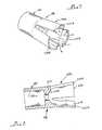
- the hammer-and-sear member 184is seen in perspective in Figures 7 and 8 . It is seen that this hammer-and-sear member 184 includes a cylindrical section 216 defining a spring recess 216a, into which the spring 192 is captively received and preloaded to make the device 110 ready for use.
- a center wall portion 218 of the member 184provides a surface 218a, which is engageable with the gas capsule 182 to move this capsule forward, and to impale the capsule on the penetrator spike (not seen in figure 6 , but recalling Figures 3-5 above).
- the member 184includes three axially extending legs 220.
- Each of these legs 220is a portion of a cone-shaped section 220a, best seen in Figures 7 and 8 .
- the transition between the circular cylindrical section 216, and the cone-shaped section 220ais indicated with a dashed line circumscribing the member 184 in Figure 7 . Forwardly of this transition, the legs 220 flare out by their own resilience. As is seen in Figure 6 , these legs 220, at an end surface 220b of each one engage upon a ring-like abutment member 222 carried within the body portion 112c.
- the end surfaces 220b of the legs 220are not formed on the radius of the cone-shape at this end of the member 184 (i.e., at the cone diameter having a center line indicated as "CL" on Figure 7 ), but are formed at a smaller radius corresponding generally with the circular diameter of the section 216 (indicated by the radius lines and character "R" of Figure 7 ).
- these end surfaces 220brest upon the abutment member 222 and transfer the spring force from spring 192 to this abutment member on a long-term basis.
- the surfaces 220bdefine cooperatively, a contact area which corresponds substantially to that of the diameter 216 of the member 184 multiplied by the radial thickness of the legs 220. This contact surface area is sufficient to prevent creeping of the polymer from which the member 184 is formed.
- the body portion 112cdefines three axially extending slots 200 (only one of which is seen in Figure 6 ), each corresponding to a respective one of the legs 220.
- the trigger sleeve 122carries three trigger blocks 122a (again, only one of which is seen in Figure 6 ) which are slidably received in the slots 200.
- the legs 220are formed at a circular (rather than conical) radius, they nest together and are received into the ring-like abutment member 222.
- the spring 192forces the hammer-and-sear member 184 forcefully forward, effecting a jet injection from the device 110, as was explained above.
- FIG. 9-15yet another alternative embodiment of a needle-free, hypodermic jet injection device is shown. Because the device illustrated in Figures 9-15 has many features that are the same as, or which are analogous in structure or function to those illustrated and described above, these features are indicated on Figures 9-15 using the same reference numeral used above, and increased by four-hundred (400).
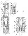
- Figures 9, 10, 10a , and 10bthe device 410 is shown in a storage condition.
- figures 11, 12 , and 12ashow the device 410 in an "inject" condition preparatory to the effecting of a hypodermic jet injection using the device.
- the device 410is in a storage configuration in which it is maintained until it is prepared for its use in administering an injection.
- the device 410includes a hand piece assembly 412, preferably fabricated principally of injection molded plastic polymers, and a including a pre-filled drug injection cartridge 414 with an end surface 416 at which is defined an injection orifice 418.
- the cartridge 414has a glass sleeve 438, and an outlet orifice 43 6b, which is sealingly closed in the storage configuration of the device 410 by a plug 444.
- the plug 444preferably takes the form of a ball member, forcibly and sealingly received into the outlet orifice 436b.
- This ball member 444is more preferably formed of Teflon material (i.e., Polytetrafluoroethylene) in order to sealingly close the outlet orifice 436b, to provide a chemically inert plug member for the cartridge 414, and to facilitate a dependable and repeatable level of force required to dislodge this plug member from the orifice 436b.
- Teflon materiali.e., Polytetrafluoroethylene
- the plug capture chamber 446provides a "bypass" passage for outward flow of the medication in the cartridge 414 around the plug member ball 444 when this ball is in this chamber.
- the chamber 446takes the form of a concave or spherical cavity having also a plurality of bypass passages 448 (only one of which is seen in the drawing Figures) allowing bypass flow of the liquid medication past the plug member 444 when this plug member is in the chamber 446.
- the body 412agenerally is formed of two main cooperative tubular sections 412b and 412c, which are threadably engaged with one another to form the hand piece assembly 412.
- the forward tubular body section 412bdefines a stepped through bore 458, a forward portion 458a of which opens at 458b forwardly on the body 412, and which inwardly of this bore opening 458a defines the internal thread section 434 for threadably receiving the external threads on a drug cartridge (recalling the description above).
- a stepped injection piston member 460Sealingly and movably received in the bore portion 458a is a stepped injection piston member 460.
- a larger diameter portion 460a of this piston memberdefines a groove 460b carrying a seal member 460c sealingly engaging with the bore portion 458a to bound a gas pressure chamber 460d.
- this body sectiondefines a tubular aft body section 462 which has an axially disposed end surface 462a at which the stepped through bore 458 opens. Inwardly of this opening, the body section 462 defines an internal thread section 464 threadably engaging onto matching threads 466 of body section 412c.
- the body portion 412ccarries a trigger sleeve 422, but the body portion 412b does not outwardly carry features like the projection 24, blocking pin 26, or recess 28 described above.
- injector 410defines a pair of spaced apart axially disposed confronting annular surfaces 504, 506, one of which is defined on the forward body portion 412b, and the other of which is defined on the trigger sleeve 422.
- the surface 506is interrupted by an axially extending resilient detent finger 508, the forward distal end portion 508a of which defines a radially inwardly extending nub 510. This radially inwardly extending nub 510 is removably received into a recess 512 defined in the radially outer surface of forward body portion 412c.
- the nub 510 and recess 512have at least one sloping surface so that the body portions 412b and 412c can be relatively rotated manually from the position seen in Figure 9 to that of Figure 11 in the direction of the arrows of Figure 9 . Because of the at least one sloping surface on the recess 512 and/or nub 510, in response to this relative rotation of the body portions 412b and 412c (recalling that body portion 412c rotates in unison with trigger sleeve 422), it is seen that the detent finger 508 is forced from the recess 512 and rides about a cylindrical outer surface portion 412d of body portion 412b as the portions 412b and 412c are relatively rotated.
- the nub 510 and guide groove 514 in cooperation with detent finger 508serve both as a detent feature, and also serve as visual and auditory indicators of the condition of the device 440. That is, in the condition of Figure 9 , the finger 508 is not aligned with the guide groove 514 and gives the impression that the trigger sleeve is not ready to move forward. On the other hand, in the condition of Figure 11 , the detent finger is aligned with the guide groove 514 and it appears that the trigger sleeve can be moved forward along this guide groove (which is true).
- the detent fingerprovides an audible “snap” or “click” sound as the nub 510 drops into the guide groove 514. This "snap” sound is an indication to the user of the device 410 that it is ready to effect an injection.
- the forward portion 412bincludes a radially outer and axially extending section 412e which provides surface roughening for better manual purchase in rotating the portions 412b and 412c relative to one another.
- the surface rougheningis provided by plural ribs or lands and grooves alternating with one another as is depicted in Figure 9 .
- the body 412 at aft portion 412c on trigger sleeve 422provides a pair of diametrically opposed plateaus 412f, which are also provided with surface roughening 412g for better manual purchase.
- the surface roughening 412gis provided by knurling.
- the trigger sleeve 422is particularly well grasped with the opposed thumb and index fingers.
- detent finger 508, recess 512, and guide groove 514do not positively prevent reverse relative rotation of the body portions 412b and 412c from the position seen in Figure 11 back to the position seen in Figure 9 .
- reverse relative rotation of the body portions from their positions seen in Figure 9 in a direction opposite to the arrow of this Figurei.e., nub 510, recess 512, and guide groove 514 are merely detent, as well as visual and auditory indicator features).
- the body portion 412bin order to cooperatively permit unidirectional relative rotation of the body portions 412b and 412c from their position of Figure 9 to the position of Figure 11 , the body portion 412b includes an axially extending protrusion 516, which is adjacent to a helical end surface portion 518.
- the body portion 412bdefines an end surface 462a upon which the bore 458 opens.
- the helical surface portion 518is a part of end surface 462a.
- the trigger sleeve 422defines a radially inwardly and axially extending key portion 520, which includes an angulated end surface portion 520a.
- the protrusion 516engages against key portion 520 (as is illustrated in Figure 10b ) so that the body portions 412b and 412c can be relatively rotated only in the direction of the arrows seen in this Figure (which is the same relative rotation illustrated by the arrows of Figure 9 ).
- the angulated end surface 520a of the key 520bears against the helical end edge surface portion 518 so that the trigger sleeve 422 cannot be moved forwardly from the storage position seen in Figure 9 . That is, the relatively large bearing area provided by the end edge surface 520a of the key 520 is sufficient to resist even attempts to manually force or jam the trigger sleeve 422 forwardly.
- the body portions 412b and 412ccan be manually rotated from the relative position of Figure 9 to that of Figure 11 .
- the angulated end surface 520a of key 520tracks along the helical surface 518 because this surface has the same pitch as the threads 464 and 466.
- the key 520comes into contact with a circumferentially disposed step 462b on the body portion 412b.
- the key 520is now in axial alignment with an axially extending keyway recess 522 defined by the body portion 412b.
- the trigger sleeve 422could be moved forwardly relative to the body 412 to effect a jet injection with the injector 410.
- the device 410includes an axial-movement resistance feature effective to prevent movement of the trigger sleeve 422 too easily in the axial forward direction, as will be further described below.
- the deviceincludes a tubular and cylindrical hammer assembly 484.
- This hammer assembly 484includes a ring-like sear carrier member 484a , and a hammer/spring seat member 486 which includes an annular spring seat surface 486a, a forwardly disposed axially surface 486b engageable both with the ring like member 484a and with the pressurized gas capsule 482, and also defines three radially extending sear pocket portions 488 each defining an axially disposed sear pocket 488a.
- the capsule 482preferably contains a pressurized gas, and most preferably contains pressurized nitrogen gas.
- a seal member 482ais carried by the body portion 412, and sealingly and movably cooperates with the capsule 482.
- the ring-like member 484aincludes three circumferentially arrayed and axially extending sear struts 490, which in the position of the hammer assembly seen in Figure 10 rest at one end in a respective one of the sear pockets 488a. At the opposite end, each of these sear struts rests in a respective one of three catch recesses 492 inwardly defined by body portion 412c., viewing Figures 10 and 14 .
- the sear struts 490are pivotally connected to the ring-like member 484a by respective integral frangible living hinge sections 490a. These frangible hinge sections 490a are fractured during assembly of the device 410 so that the device is positively a single-use device.
- the device 410includes a spring 494 urging hammer assembly 484 forwardly.
- An end cap 502captures the spring 494 and the hammer assembly 484 in the aft portion of the handpiece 412.
- the end cap 502includes an axially elongate recoil buffer nose 502a, extending toward the hammer member 486.
- the hammer member 486includes a tubular recoil buffer portion 486b extending axially toward the nose portion 502a of the end cap 502.
- the ring like portion 484ais disposed relatively close axially to the aft end of the struts 490.
- the axial depth of the pockets 488a on hammer member 486is greater than the axial projection of the struts 490 aft of the ring-like portion 484a. Consequently, when the device 410 is assembled, the surface 486b of the hammer member 486 engages the ring-like member 484a well before the aft end of the struts 490 are seated completely in sear pockets 488a (although the sear members are received partially into these pockets so as to guide the sear members).
- Figure 14illustrates the hammer and sear structure described above immediately after the moment of sear release (i.e., a split second before effecting of a hypodermic jet injection by use of the device 410).
- the trigger sleeve 422has been moved forwardly sufficiently (indicated by the axially directed arrows in Figure 14 ) that the trigger block portions 422a have dislodged the forward end of the sear struts 490 from their repose in catch recesses 492. Consequently, the hammer assembly 484 has started forward toward the gas capsule 482, and a jet injection will be effected when the pressurized gas within this capsule is utilized, as has been described above.
- the trigger sleeve 422defines three radially inwardly extending trigger blocks 422a. These trigger blocks 422a are slidably received into respective axially extending slots 500 defined by the body portion 412c. As Figure 14a illustrates, the trigger blocks 422a are preferably provided with a fillet 422b at the radially outer intersection of these trigger blocks with the remainder of trigger sleeve 422. On the other hand, the adjacent portion of housing 412c (i.e., along the radially outer edge of the slots 500) is not provided with a matching "round,” but instead has a comparatively sharp edge 524.
- This sharp edge 524engages against the fillet 422b to frictionally resist axial movement of the trigger sleeve 422 relative to the body portion 412c until a sufficient axial force has been applied by a user of the device 410. Once this threshold value of axial force has been applied by the user of the device 410, the trigger sleeve 422 slides forward to effect a jet injection, as has been described. Most preferably, the interference relationship of the trigger blocks 422a with the fillets 422b is provided only for an initial portion of the forward firing movement of the trigger sleeve 422.
- the interference force requirementis discontinued, and the axial force required on the trigger sleeve 422 in order to dislodge the struts 490 then provides some resistance to the movement of the trigger sleeve until the struts 490 are dislodged, and the device 410 discharges.
- This threshold level of axial force required of a user on the trigger sleeve 422 in order to effect initial axial movement of this trigger sleeveinsures that the trigger sleeve does not move forward inadvertently, and also insures that when the user moves this trigger sleeve forward, it is a deliberate action and is because the user is ready and intends to effect a jet injection using the device 410. Further, this selected resistance to forward motion of the trigger sleeve 422 insures that the device 410 is pressed against the skin of the person who is to receive the jet injection with a selected level of axial force.
- the surface 416is most preferably pressed against the skin of the recipient of the jet injection with an axial force of about 3 to 4 pounds.
- This level of axial forceis such that it provides the optimal degree of pressure of the surface 416 on the skin of the recipient, stretching the skin just sufficiently to insure an optimal jet injection, and insuring that the surface 416 of the injector 410 maintains contact with the skin during the brief interval of the injection.
- the device 410has a condition as seen in Figure 15 for a relatively short interval during an injection, and it will be appreciated that pressurized gas from the capsule 482 (communicated to chamber 460b) is also effective to urge the capsule 482 rearwardly (leftwardly, as seen in Figure 15 ). Consequently, the capsule 482 will recoil leftwardly from the position seen in Figure 15 back toward its position of Figures 10 and 12 . If the capsule 482 were allowed to recoil leftwardly a distance sufficient to move leftwardly of the seal 482a, then pressurized gas would be vented from the device 410. In order to prevent this venting of pressurized gas, the recoil buffer portions 486b and 502a confront and contact one another. Consequently, the capsule is stopped in its leftward recoil motion at the position of this capsule illustrated in Figures 10 and 12 .
Landscapes
- Health & Medical Sciences (AREA)
- Vascular Medicine (AREA)
- Engineering & Computer Science (AREA)
- Anesthesiology (AREA)
- Biomedical Technology (AREA)
- Heart & Thoracic Surgery (AREA)
- Hematology (AREA)
- Life Sciences & Earth Sciences (AREA)
- Animal Behavior & Ethology (AREA)
- General Health & Medical Sciences (AREA)
- Public Health (AREA)
- Veterinary Medicine (AREA)
- Infusion, Injection, And Reservoir Apparatuses (AREA)
Abstract
Description
- This application is a Continuation-in-Part of United States Patent Application, Serial No.
09/195,334, filed 18 November 1998 09/252,131, filed 18 February 1999 - The present invention relates generally to a single-use disposable needle-less (or needle-free) hypodermic jet injection device. Particularly, this invention relates to such a jet injection device which comprises a hand-held injector having a pre-filled drug cartridge sealingly carrying injectable medication, a sealed cylinder of pressurized gas, a pre-energized discharge mechanism for penetrating the gas cylinder, and a trigger device for releasing the discharge mechanism. Features are provided which simultaneously unseal the drug cartridge and prepare the device for performing a jet injection when a user of the device changes it from a storage configuration to a use configuration. When the user actuated the injection device, the trigger device releases the discharge mechanism to penetrate the gas cylinder, which drives a piston of the drug cartridge to effect a hypodermic jet injection.
- Needle-less or needle-free hypodermic jet injection devices have been in commercial use for over 40 years. A number of these devices have used pressurized gas to power a hypodermic jet injection. The related technology includes a number of teachings for gas-powered injection devices, including:
U.S. Patent No. 4,596,556, issued 24 June 1986 to J. Thomas Morrow, et al. ;U.S. Patent No. 4,913,699; issued 3 April 1990 to James S. Parsons ; andU.S. Patent No. 5,730,723, issued 24 March 1998, to Thomas P. Castellano, et al. WIPO publicationWO 97/37705 - The Morrow, et. al. '556 patent is believed to teach a reusable hypodermic jet injection device in which a housing receives a shell or cartridge having a bore leading to a discharge aperture. Within the bore is received both a plunger sealingly engaging the bore, and a pressurized gas cylinder which rests against the plunger. The injection device includes a ram which has a penetrating tip confronting a penetrable wall section and seal of the gas cylinder, and a discharge mechanism for driving the ram through the penetrable wall section of the gas cylinder when a trigger device is released. Discharge of the pressurized gas from the cylinder drives the plunger to effect a jet injection, and also drives the seal of the gas cylinder to effect resetting of the discharge mechanism. The shell with its plunger, and spent gas cylinder, is discarded after an injection; and a new shell pre-filled with medication and with a new gas cylinder is used for each injection.
- The Parsons '699 patent is believed to teach a single-use jet injector which is totally discarded after one use. This injector is believed to have a body with a pair of gas chambers separated by a breakable valve. One of the gas chambers contains a pressurized gas, while the other chamber is sealingly bounded by a piston which drives a plunger. The plunger sealingly bounds a chamber into which a dose of medication is loaded by the user before the injection. This medication dose chamber leads to an injection orifice so that when the valve is broken, the piston and plunger are moved by pressurized gas communicated to the second chamber, and the plunger drives the medication forcefully out of the injection orifice to form an injection jet. After a single use, the device is discarded.
- The Castellano '723 patent, which was issued in 1998 and which does not cite the earlier Parsons '699 patent, is believed to teach substantially the same subject matter as Parsons et al.
- WIPO publication
WO 97/37705 - The Weston device is thought to have several deficiencies: such as difficult and costly manufacturing and sterilization processes, because pressurized gas and a drug dose need to be contained in the same package; and including a possible inability to endure long-term storage while still retaining the gas pressure in the gas spring to power an injection, and also maintaining the medication integrity. In other words, the gas pressure spring of the Weston device contains only a small quantity of gas, and depends upon the sealing relationship of the ram of this spring with a cylinder within which the ram is movably and sealingly received in order to retain this gas pressure. Even a small amount of gas leakage over time will be enough to render this injector inoperative.
- In view of the above, it is desirable and is an object for this invention to provide a needle-less hypodermic jet injection device which reduces the severity of or avoids one or more of the limitations of the conventional technology.
- Thus, it is an object of this invention to provide a single-use, disposable, needle-free gas-powered hypodermic jet injector utilizing a pressurized gas source which is hermetically sealed until the moment of injection.
- Further, an object of this invention is to provide such a gas powered jet injector in which the device has a storage configuration and a use configuration. In the storage configuration, the device is safe, with the drug cartridge sealed closed, and is incapable of effecting a jet injection. In the use configuration, the device is prepared for making a jet injection, with the drug cartridge opened in preparation for this injection.
- Additionally, an object for this invention is to provide such an injection device having a multi-function component which alternatively maintains the injector in a safe storage condition, and also allows a user to place the injection device into a use condition preparatory for performing a jet injection. When the user placed the device into the use configuration, the multi-function component prepares the jet injection device by effecting unsealing of the previously sealed drug cartridge, and also removes a safety block from an obstructing position relative to a trigger of the device. Thereafter, the trigger of the injector can be manually activated by a user of the device to perform an injection.
- According to the present invention there is provided a needle-less hypodermic jet injection device according to claim 1 or claim 2.
- Accordingly, a needle-less hypodermic jet injection device embodying this invention includes, for example: a hand piece assembly having a body including a drug injection cartridge with a medication cylinder pre-tilled with substantially incompressible liquid medication such that substantially no ullage volume exists in the medication cylinder, the medication cylinder leading to an outlet orifice a plug-capture chamber and a drug injection nozzle, a sealing member sealingly and movably received in the outlet orifice, and a drug-injection piston; the hand piece assembly further defining a first bore within the body for movably receiving a gas-power piston, a gas power piston movably received in the first bore and having a ram portion extending into the drug injection cartridge to abut with the drug-injection piston, the body and gas-power piston cooperating to define a first variable-volume chamber in the first bore; the body also defining an elongate second bore in gas communication with the first bore and separated therefrom by a center wall portion of the body, a cylindrical gas capsule received into the second bore, the gas capsule having a penetrable wall section disposed toward the center wall, the center wall carrying a penetrator disposed toward the penetrable wall section of the gas capsule, and the hand piece assembly carrying a discharge mechanism including a trigger member outwardly disposed on the body and a hammer movable in the body in response to actuation of the trigger to forcefully move the gas capsule in the second bore so as to impale the gas capsule at the penetrable wall section thereof upon the penetrator and thus to communicate pressurized gas to the first chamber; whereby, the pressurized gas in the first chamber drives the gas-power piston to effect a hypodermic jet injection from the drug injection cartridge, and the body and trigger member cooperatively defining a first relative position in which the ram portion confronts but does not displace the injection piston so that the sealing member is disposed in the outlet orifice to maintain the drug injection cartridge sealingly closed, and the body and trigger member in a second relative position preparatory to effecting a jet injection causing the ram portion to abut and move the drug injection piston to a second position displacing the drug injection piston to a second position so that the sealing member is displaced from the outlet orifice into the plug-capture chamber by the liquid medication and unseals the drug injection cartridge.
- Preferred additional features of the invention are defined in claims 3 to 20 preferred embodiments of the invention include the following. A needle-less hypodermic jet injection device comprising a pre-filled drug injection cartridge including a medication cylinder having an outlet orifice, an injection nozzle, a flow path communicating the outlet orifice to the injection nozzle, a plug member in a first position sealingly disposed in the flow path, a drug-injection piston in a first position cooperating with the medication cylinder to define a variable-volume chamber of first selected size, and a dose of substantially incompressible liquid medication substantially filling the variable-volume chamber at the first size with substantially no ullage volume. The drug-injection piston having a second position cooperating with the medication cylinder to define a variable-volume chamber of second selected size smaller than the first selected size, so that the incompressible liquid medication displaces the plug member from the first position of sealing disposition in the flow path to a second position of capture in the flow path, the medication cylinder and the plug member in the second position thereof cooperatively defining an open flow path between the variable-volume chamber and the injection nozzle. A hand piece assembly having a body holding the drug injection cartridge, the hand piece assembly including means for forcefully moving the drug injection piston from the second position to a third position so as to reduce the volume of the variable-volume chamber substantially ejecting the dose of liquid medication via the injection nozzle. The hand piece assembly further including a first body portion holding the drug injection cartridge, and an abutment member selectively movable into engagement with the drug injection piston to move the drug injection piston from the first position to the second position.
- Additional objects and advantages of this invention will appear from a reading of the following detailed description of a single exemplary preferred embodiment, taken in conjunction with the appended drawing Figures, in which the same reference numeral is used throughout the several views to indicate the same feature, or features which are analogous in structure or function.
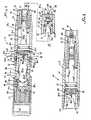
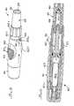
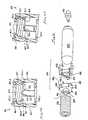
Figure 1 provides an exterior side elevation view of a single-use, needle-less hypodermic jet injector device embodying the present invention, and in which the device is in a "storage" configuration;Figure 2 is an exterior side elevation view of the injector device seen inFigure 1 , but with the device shown in an "inject" configuration preparatory to effecting a hypodermic jet injection;Figure 3 provides a longitudinal cross sectional view through the needle-less hypodermic jet injection device ofFigure 1 , and shows the device in the "storage" configuration;Figure 4 is a fragmentary cross sectional view similar toFigure 3 , but shows the hypodermic jet injection device in the "inject" configuration;Figure 5 is also a fragmentary cross sectional similar toFigures 3 and 4 , but shows the hypodermic jet injection device during the process of effecting a jet injection;Figure 6 is a fragmentary cross sectional view similar to a portion ofFigure 4 , but shows a respective portion of an alternative embodiment of a single-use, needle-less hypodermic jet injection device according to the present invention;Figure 7 is a perspective view of a portion of the device seen inFigure 6 ;Figure 8 provides a cross sectional view of the portion of the device seen inFigure 7 ;Figure 9 provides an exterior side perspective view of an alternative embodiment of a single-use, needle-less hypodermic jet injector device embodying the present invention, and in which the device is in a "storage" configuration;Figure 10 provides a longitudinal cross sectional view through the needle-less hypodermic jet injection device ofFigure 9 , and shows the device in the "storage" configuration;Figure 10a is a fragmentary cross sectional view taken along line a-a offigure 10 ;Figure 10b is a fragmentary longitudinal cross sectional view of a portion of the device ofFigure 10 , with portions removed or broken away for clarity of illustration, with cooperating parts shown in their "storage" positions, and is shown at an enlarged size;Figure 11 is an exterior side perspective view of the injector device seen inFigure 9 , but with the device shown in an "inject" configuration preparatory to effecting a hypodermic jet injection;Figure 12 is a longitudinal cross sectional view similar toFigure 10 , but shows the hypodermic jet injection device in the "inject" configuration;Figure 12a is a fragmentary longitudinal cross sectional view similar toFigure 10b , but with cooperating parts in their "inject" positions, and is also shown at the same enlarged size;Figure 13 provides an exploded perspective view of parts of the injection device ofFigures 9-12 ;Figure 14 is a greatly enlarged fragmentary cross sectional view similar to a portion ofFigure 12 , but shows the hypodermic jet injection device during the process of effecting a jet injection;Figure 14a is a fragmentary cross sectional view taken at plane 14a-14a ofFigure 14 ; andFigure 15 is a longitudinal cross sectional view similar toFigures 10 and12 , but showing the device after completion of an hypodermic jet injection.- Viewing
Figure 1 , a needle-free, hypodermicjet injection device 10 is shown in a storage configuration in which it is maintained until it is prepared for its use in administering an injection. In this storage configuration, the device is incapable of effecting a jet injection, is safe, and can be stored for a comparatively long time while requiring only a moment of preparation before it can be used to make a jet injection of the medication within thedevice 10. - The
device 10 includes ahand piece assembly 12, preferably fabricated principally of injection molded plastic polymers, and with a body 12a including a pre-filleddrug injection cartridge 14. The word "drug" as used herein is intended to encompass, for example, and without limitation, any medication, pharmaceutical, therapeutic, vaccine, or other material which can be administered by jet injection. Essentially, such an injectable medication is in the form of a substantially incompressible liquid, and as will be seen, this liquid substantially fills the drug injection cartridge so that no ullage volume of compressible gas is present in this cartridge. - The pre-filled
drug injection cartridge 14 has anend surface 16 at which is defined a fine-dimensioninjection orifice opening 18. When thedevice 10 is used to effect an injection, a high velocity jet of liquid medication issues from this orifice (as is indicated by arrow 20 ofFigure 5 ). To use thedevice 10, it is first placed in an "inject" configuration, theend surface 16 is pressed against the skin of a patient who is to receive the jet injection, and then thedevice 10 is triggered so that the jet 20 issues out and penetrates the skin. Thus, the liquid medication enters the tissues of the patient without the use of a hypodermic needle. - Placing the
device 10 in the "inject" configuration is effected manually by a user of thedevice 10 who rotates afirst portion 12b of the body 12a relative to a second portion 12c. As is seen inFigure 1 , the body portion 12c carries atrigger sleeve 22, while theportion 12b carries aprojection 24 abutting this sleeve. Theprojection 24 and a blockingpin 26 cooperate to prevent thebody portions 12b and 12c from being relatively rotated except in the direction of the arrow ofFigure 1 . When a user effects this relative rotation of thebody portions 12b and 12c through a rotation of almost 360°, then this relative rotation aligns theprojection 24 with arecess 28 on thetrigger sleeve 22, reveals the abbreviation of the word "inject" (indicated onFigure 2 by the letters "INJ") on the body portion 12c. - This relative rotation of the
body portions 12b and 12c also effects a selected relative axial movement of these body portions toward one another (as will be further described below), and places thedevice 10 in the "inject" configuration seen inFigure 2 . In this "inject" configuration, thedevice 10 is positioned with itssurface 16 against the skin of the person who is to receive the injection, and an axial pressure is applied to thetrigger sleeve 22. Thetrigger sleeve 22 moves axially along the body portion 12c, and this movement triggers thedevice 10 to effect injection jet 20 (recallingFigure 5 ). - Turning now to
Figures 3, 4 , and5 , in conjunction with one another,Figure 3 shows thedevice 10 in the storage configuration ofFigure 1 preparatory to giving an injection. InFigure 4 shows the device in the "inject" configuration, andFigure 5 shows the device during the brief interval of an injection. In these Figures, it is seen that thedrug cartridge 14 includes acylindrical body 30 defining anexternal thread section 32. Thisexternal thread 32 is threadably received by a matchinginternal thread section 34 of thebody portion 12b. Preferably, a thread locking compound, such as an anaerobic adhesive, is applied to thethreads 32 of thecartridge 14 when it is assembled to thebody portion 12b during manufacture of thedevice 10. Alternatively, a self-locking thread design or a thread-locking feature may be used on thedevice 10 to prevent thedrug injection cartridge 14 from being removed from thedevice 10. Thus, the cartridge is not removable from thedevice 10, and thedevice 10 andcartridge 14 are disposed of after the first and only injection effected with thedevice 10. - An advantageous feature of the
device 10 embodying the present invention, and one which results from this construction of the device, is that theinjection cartridge 14 may be manufactured and filled at a drug company (without the drug manufacture having to be concerned with handling capsules of pressurized gas), the gas pressure capsule of the device may be manufactured and filled at a factory devoted to this item (without this manufacturer having to handle drugs), and the hand piece assembly of the device may be manufactured at yet another location, if desired. Subsequently, completion of thedevice 10 requires merely the combining of the hand piece assembly, gas capsule, and drug injection cartridge. - The
body 30 ofcartridge 14 defines a stepped throughbore 36 having a larger diameter portion 36a which extends substantially the length of thebody 26. Adjacent to the forward end of the body 30 (i.e., adjacent to the end defining surface 16), thebore 36 steps down and defines an outlet orifice 36b. It is seen that the bore portion 36a and outlet orifice 36b are defined by aglass sleeve 38 which is received into a moldedplastic body 40. An O-ring type ofseal member 42 prevents leakage between theglass sleeve 38 and thebody 40. - As those who are ordinarily skilled in the pertinent arts will understand, many medications are not suitable for long-term storage in contact with plastics, but will store satisfactorily in contact with glass. Thus, this construction of the
cartridge 14 makes it suitable for long-term storage of even medications of this nature. However, for medications that will store satisfactorily in contact with plastic polymers, this construction detail is optional and the entireinjection cartridge body 30 may be formed of a selected polymer. - In the embodiment of
cartridge 14 having theglass sleeve 38, the outlet orifice 36b is sealingly closed in the storage configuration of thedevice 10 by aplug 44. Importantly, viewingFigures 3-5 , it is seen that thecartridge 14 defines a plug-capture chamber 46 immediately outside of the outlet orifice 36b (i.e., rightwardly of this outlet orifice, viewingFigures 3-5 ). Theplug capture chamber 46 includes aradial array 46a of individual radially inwardly and axially extendingribs 48 disposed in a spaced relation to the outlet orifice 36b. Theseribs 48 are arrayed radially about and in a transition bore portion 18a leading to theinjection orifice 18. Thus, as will be seen, theplug member 44 can be received into the plug-capture chamber 46 and be supported on theribs 48 without it blocking theinjection orifice 18. - Sealingly and movably received in the bore section 36a is a
resilient piston member 50. This piston member defines multiple circumferential grooves 50a interdigitated with sealing ribs 50b. The sealing ribs 50b sealingly and movingly engages the bore 36a of the injection cartridge (i.e., with the bore 36a ofglass sleeve 38 in this case). Thepiston member 34 andbody 30 cooperatively define amedication chamber 52 communicating outwardly of thecartridge 14 via theinjection orifice 18. Prior to its use to effect an injection, theorifice 18 of each fresh andpre-filled device 10 will ordinarily also be sealed by an adhesively-applied, peel-off type of sealing membrane, which may be formed, for example, of foil or of a polymer/paper laminate. Such peel-off seals are conventional and well known, and for this reason, the seal formerly oncartridge 14 ofdevice 10 as seen inFigure 3 is not shown in the drawing Figures. - Further considering the
cartridge 14, it is seen that thepiston member 50 defines anabutment surface 54 confronting the opening ofbore 36 onbody 30. Thissurface 54 is abutted by an end surface 56 on an injection ram of the hand piece assembly 12 (which injection ram will be further described below). In the storage configuration of thedevice 10, the end surface 56 confrontspiston 50, but does not displace it from the position seen inFigure 3 . In this storage configuration of thedevice 10, thechamber 52 is sealed and is substantially full of incompressible liquid, without any substantial ullage volume of compressible gas being in thechamber 52. The injection ram will be understood as effective during a jet injection to forcefully move thepiston 50 inwardly of the bore section 36a toward the outlet orifice 36b - Considering now the
hand piece assembly 12 in greater detail, as seen inFigures 1-5 , it is seen that the body 12a generally is formed of two main cooperativetubular sections 12b and 12c, which are threadably engaged with one another to form thehand piece assembly 12. Preferably both of thebody sections 12b and 12c, as well as other components of thedevice 12 not otherwise identified as being made of some other material, are all formed of plastic polymers. Further, the preferred process for making thedevice 10 is by injection molding of the components formed of plastic polymer, so that manufacturing costs are very low. Materials utilization for thedevice 10 is very small as well, so that disposing of the device after a single injection does not cause a serious environmental concern. - The forward
tubular body section 12b defines a stepped throughbore 58, aforward portion 58a of which opens at 58b forwardly on thebody 12, and which inwardly of this bore opening 58a defines theinternal thread section 34 for threadably receiving theexternal threads 32 on thedrug cartridge 14. Sealingly and movably received in thebore portion 58a is a steppedinjection piston member 60. Alarger diameter portion 60a of this piston member defines a groove 60b carrying aseal member 60c. Theseal member 60c movingly engages sealingly with thebore portion 58a and bounds agas pressure chamber 60d, which is to the left of this piston member as seen inFigures 3, 4 , and5 . It is to be noted that inFigures 3 and 4 , thischamber 60d is at a minimal volume, and so the lead line fromreference numeral 60d extends into the interface of thepiston member 60 with the housing portion 12c. - A
smaller diameter portion 60e of thepiston member 60 is elongate and extends in thebore 58 to also be received into the bore portion 36a of thedrug cartridge 14, as is seen inFigure 3 in the storage configuration of thedevice 10. Thepiston portion 60e defines the end surface 56 which confronts and abuts thesurface 54 of thepiston member 50 of andrug cartridge 14. Thus, thepiston portion 60e provides the injection ram of thedevice 10. - Considering the
forward body section 12b in still greater detail, it is seen that this body section defines a tubularaft body section 62. This aft body section includes an axially disposed end surface 62a at which the stepped throughbore 58 opens, and which defines aninternal thread section 64 threadably engaging onto matchingthreads 66 of body section 12c. For purposes of explanation, and without limitation of the present invention, thethreads - As is seen comparing
Figures 1 and 2 , thedevice 10 is converted from its storage to its "inject" configuration by rotating thebody portions 12b and 12c in a relative rotational direction that threads these body portions together alongthreads body sections 12b and 12c bringsprojection 24 into alignment withrecess 28 ontrigger sleeve 22, and makes possible the subsequent triggering of thedevice 10.
Still consideringFigures 2 and3 , it is seen that the aft body portion 12c outwardly defines thethread section 66 and slidably carries thetrigger sleeve 22. Adjacent to thethread section 66, the body portion 12c carries an O-ring type of sealingmember 68 which sealingly engages thebody portion 12b both when the body portions are in their "storage" relative configuration ofFigure 3 , and also when these body portions are in their "inject" relative positions as is seen inFigures 4 and5 . - Body portion 12c defines a stepped through
bore 70 which is substantially closed at the end of this bore adjacent to theforward body portion 12b by awall member 72. Thiswall member 72 defines a stepped throughbore 74 in a larger diameter part of which is seated adisk part 76 of apenetrator member 78. Thispenetrator member 78 includes a hollow penetrator spike 80 which itself has abore 80a communicating through thewall member 72 via the smaller diameter portion ofbore 74. Thus, thebore 70 is communicated to thechamber 60d adjacent toinjection piston 60 in thebody portion 12b. - Slidably received in the
bore 74 adjacent to and confronting thepenetrator member 78 is agas pressure capsule 82. Thisgas pressure capsule 82 includes a body 82a, having a cylindrical outer wall portion 82a'. Thecapsule 82 is also necked down at a forward end to provide a reduced diameter portion 82b leading to an axially disposed end surface 82c defined by apenetrable wall section 82d (the wall section being indicated by the arrowed numeral inFigure 3 ). Thegas capsule 82 is preferably formed of metal, and contains a supply of pressurized gas. Because the pressurized gas is contained in thecapsule 82 until the moment of injection, the plastic parts of thedevice 10 are not exposed to or stressed by this pressurized gas until an injection is effected using thedevice 10. For this reason, thedevice 10 is believed to have a much more reliable storage life then prior devices which attempt to contain pressurized gas in a plastic or plastic-composite containment. - The
wall section 82d confronts and is spaced slightly from thepenetrator spike 80. At an opposite or aft end of thecapsule 82, this capsule defines an outwardly rounded end wall 82e. - Also slidably received into the
bore 70 and confronting the end 82e ofcapsule 82 is tubular andcylindrical hammer member 84. Thishammer member 84 defines an end surface 84a which is engageable with the surface 82e ofcapsule 82, anaxially extending groove 86 having an end wall at 86a (into which adowel pin 88 is received), and an axial protrusion at 90 which serves to center aspring 92. - The
dowel pin 88 is engaged in a first position (i.e., in the "storage" configuration of the device 10) at end 86a ofgroove 86, and the other end of this pin rests upon a metal (i.e., preferably hardened steel)sear pin 94 carried by the body portion 12c. Thus, as is seen inFigures 3 and 4 , thehammer 84 is maintained in a "cocked" position with thespring 92 pre-loaded between thehammer 84 and a spring seat member 96 threadably engaging into the end of body portion 12c. - In order to provide for movement of the
trigger sleeve 22 to effect release of thehammer 84, the body portion 12c defines anaxially extending slot 100, and thetrigger sleeve 22 carries a radially inwardly extendingtrigger block 22a, which is slidably received in thisslot 100 and which confronts thedowel pin 88, as is seen inFigure 3 . Also, anend cap 102 is adhesively retained onto thetrigger sleeve 22 and closes the end of this trigger sleeve so that a user's thumb, for example, may be used to effect forward movement of the trigger sleeve when an injection is to be effected. It will be understood that thetrigger sleeve 22 may alternatively be grasped between the thumb and fingers, for example, to position thedevice 10 for making an injection, and then effecting forward movement of thetrigger sleeve 22 to effect this injection. - However, as was pointed out above in connection to the comparison of
Figures 1 and 2 , thedevice 10 is first placed by a user into its "inject" configuration before a jet injection can be effected. This conversion of thedevice 10 from its "storage" configuration to its inject configuration is effected by relative rotation of thebody portions 12b and 12c, as is indicated by the arrow onFigure 1 . As is seen inFigure 2 , this relative rotation of thebody portions 12b and 12c brings theprojection 24 into engagement with blockingpin 26 and into alignment withrecess 28, so that thetrigger sleeve 22 is movable in the axial direction towardbody portion 12b. However, viewingFigure 4 , it is seen that this relative rotation of thebody portions 12b and 12c also threads body portion 12c by substantially one thread pitch dimension into thebody portion 12b. - Because the body portion 12c and
wall member 72 are abuttinginjection piston member 50, thispiston member 50 is moved rightwardly, viewingFigure 4 , by substantially one thread pitch dimension. Consequently, theram portion 60e of theinjection piston 60 moves forward andforces piston 50 forwardly by a sufficient amount that plugmember 44 is dislodged hydraulically (recalling that the liquid medication inchamber 52 is substantially incompressible) from the outlet orifice 36b and into plug-capture chamber 46. In thischamber 46, theplug member 44 is retained an rests upon theribs 48 while these rib provide a flow path leading around theplug member 44 from the outlet orifice 36b to theinjection orifice 18. - Although the conversion of
device 10 from its "storage" configuration to its "inject" configuration unseals theinjection cartridge 14, this is not detrimental to the integrity of the medication inchamber 52 because it happens mere moments before thedevice 10 is used to inject the medication into a patient. This injection is effected by placement of thedevice 10 with itssurface 16 against the skin at the intended location of injection, and sliding oftrigger sleeve 22 forward (which also assists in seeing that thedevice 10 is held firmly to the skin), so that thetrigger block 102 slides alongslot 100 to dislodge thedowel pin 88 fromsear pin 94, viewingFigure 5 . - As is seen in
Figure 5 , the result is that thehammer member 84 is driven forward byspring 92, impacts thecapsule 82, and impales this capsule atpenetrable wall 82d, as is seen inFigure 5 . The result is thepenetrator spike 80 penetrates the wall 82c of thecapsule 82, and allows pressurized gas from this capsule to flow along thebores chamber 60d. This pressurized gas inchamber 60d drivespiston member 60 forwardly, so that thepiston 50 in bore 36a is also driven forwardly. Forward movement ofpiston 50 drives the liquid medication out ofchamber 52, past theplug member 44 in plug-capture chamber 46, and out ofinjection orifice 18, forming injection jet 20. - After the jet injection depicted in
Figure 5 , thedevice 10 is disposed of by the user of the device, and it is not again used. That is, thedevice 10 is a single-use device and is not designed or intended to be recharged or refilled. This design of thedevice 10 insures safety for those receiving an injection by use of thedevice 10 because they can be sure that only a new and never before used device is used to give them the injection. Further, thedevice 10 provides for long-term storage of the device and its pre-filled medication, so thatdevices 10 may be stockpiled in anticipation of such events as mass inoculations. Thedevice 10 may be used under exigent circumstances as well, since it requires only a few seconds or less to convert it from its "storage" configuration to its "inject" configuration, after which the jet injection is immediately effected. Figure 6 provides a fragmentary view of an alternative embodiment of the jet injection device according to this invention. InFigure 6 , only the aft or trigger assembly end of the device is illustrated. The forward end of the device and its pre-filled medication injection cartridge may be substantially as depicted and described above. Because the device illustrated inFigures 6-8 has many features that are the same as, or which are analogous in structure or function to those illustrated and described above, these features are indicated onFigures 6-8 using the same reference numeral used above, and increased by one-hundred (100).- Viewing
Figures 6-8 in conjunction with one another, it is seen that theinjection device 110 includes a body portion 112c, which is necked to a slightly smaller diameter aft portion at 214. This aft portion defines a plurality ofcircumferential barbs 214a, and anend cap 202 is received on these barbs and is permanently engaged there by a matching set of inwardly extending barbs 202a. Slidably received in this body portion 112c is a one-piece molded hammer-and-sear member 184. - Preferably, this
member 184 is molded of plastic polymer. The hammer-and-sear member 184 is seen in perspective inFigures 7 and 8 . It is seen that this hammer-and-sear member 184 includes acylindrical section 216 defining aspring recess 216a, into which thespring 192 is captively received and preloaded to make thedevice 110 ready for use. Acenter wall portion 218 of themember 184 provides asurface 218a, which is engageable with thegas capsule 182 to move this capsule forward, and to impale the capsule on the penetrator spike (not seen infigure 6 , but recallingFigures 3-5 above). In order to hold the hammer-and-sear member against the pre-load ofspring 192, and to resist the pressure of this spring over a long term themember 184 includes three axially extendinglegs 220. - Each of these
legs 220 is a portion of a cone-shapedsection 220a, best seen inFigures 7 and 8 . The transition between the circularcylindrical section 216, and the cone-shapedsection 220a is indicated with a dashed line circumscribing themember 184 inFigure 7 . Forwardly of this transition, thelegs 220 flare out by their own resilience. As is seen inFigure 6 , theselegs 220, at an end surface 220b of each one engage upon a ring-like abutment member 222 carried within the body portion 112c. As is best appreciated by consideration ofFigure 7 , it is seen that the end surfaces 220b of thelegs 220 are not formed on the radius of the cone-shape at this end of the member 184 (i.e., at the cone diameter having a center line indicated as "CL" onFigure 7 ), but are formed at a smaller radius corresponding generally with the circular diameter of the section 216 (indicated by the radius lines and character "R" ofFigure 7 ). During storage of thedevice 110, these end surfaces 220b rest upon theabutment member 222 and transfer the spring force fromspring 192 to this abutment member on a long-term basis. - In order to prevent creep of the plastic polymer material from which the
member 184 is formed, the surfaces 220b define cooperatively, a contact area which corresponds substantially to that of thediameter 216 of themember 184 multiplied by the radial thickness of thelegs 220. This contact surface area is sufficient to prevent creeping of the polymer from which themember 184 is formed. - In order to effect release of the hammer-and-
sear member 184 when it is desired to effect a jet injection with thedevice 110, the body portion 112c defines three axially extending slots 200 (only one of which is seen inFigure 6 ), each corresponding to a respective one of thelegs 220. As is seen inFigure 6 , thetrigger sleeve 122 carries three trigger blocks 122a (again, only one of which is seen inFigure 6 ) which are slidably received in theslots 200. When thistrigger sleeve 122 is moved forward, the trigger blocks 122a simultaneously force respective ones of thelegs 220 radially inwardly and out of engagement with theabutment member 222, overcoming both the inherent resilience of these legs and the component of spring force resulting from the radial flaring of these legs. It will be appreciated that in view of this combination of inherent resilience and outward flare of thelegs 220, there is virtually no risk that thedevice 110 will trigger except in response to deliberate forward movement of thetrigger sleeve 122. - Because the
legs 220 are formed at a circular (rather than conical) radius, they nest together and are received into the ring-like abutment member 222. Thus, thespring 192 forces the hammer-and-sear member 184 forcefully forward, effecting a jet injection from thedevice 110, as was explained above. - Viewing now
Figures 9-15 , yet another alternative embodiment of a needle-free, hypodermic jet injection device is shown. Because the device illustrated inFigures 9-15 has many features that are the same as, or which are analogous in structure or function to those illustrated and described above, these features are indicated onFigures 9-15 using the same reference numeral used above, and increased by four-hundred (400). InFigures 9, 10, 10a , and10b , thedevice 410 is shown in a storage condition. On the other hand,figures 11, 12 , and12a show thedevice 410 in an "inject" condition preparatory to the effecting of a hypodermic jet injection using the device. - Viewing first
Figures 9, 10, 10a and10b , it is seen that thedevice 410 is in a storage configuration in which it is maintained until it is prepared for its use in administering an injection. Thedevice 410 includes ahand piece assembly 412, preferably fabricated principally of injection molded plastic polymers, and a including a pre-filleddrug injection cartridge 414 with anend surface 416 at which is defined aninjection orifice 418. Thecartridge 414 has aglass sleeve 438, and an outlet orifice 43 6b, which is sealingly closed in the storage configuration of thedevice 410 by aplug 444. - In this embodiment, the
plug 444 preferably takes the form of a ball member, forcibly and sealingly received into the outlet orifice 436b. Thisball member 444 is more preferably formed of Teflon material (i.e., Polytetrafluoroethylene) in order to sealingly close the outlet orifice 436b, to provide a chemically inert plug member for thecartridge 414, and to facilitate a dependable and repeatable level of force required to dislodge this plug member from the orifice 436b. Importantly, viewingFigure 10 , it is seen that thecartridge 414 also defines a plug-capture chamber 446 immediately outside of the outlet orifice 436b from theglass sleeve 438. Further to the discussion above, it will be appreciated that theplug capture chamber 446 provides a "bypass" passage for outward flow of the medication in thecartridge 414 around theplug member ball 444 when this ball is in this chamber. In this embodiment, thechamber 446 takes the form of a concave or spherical cavity having also a plurality of bypass passages 448 (only one of which is seen in the drawing Figures) allowing bypass flow of the liquid medication past theplug member 444 when this plug member is in thechamber 446. - Considering now the
hand piece assembly 412 in greater detail, as shown inFigures 9-10b , it is seen that the body 412a generally is formed of two main cooperativetubular sections 412b and 412c, which are threadably engaged with one another to form thehand piece assembly 412. The forward tubular body section 412b defines a stepped throughbore 458, a forward portion 458a of which opens at 458b forwardly on thebody 412, and which inwardly of this bore opening 458a defines theinternal thread section 434 for threadably receiving the external threads on a drug cartridge (recalling the description above). - Sealingly and movably received in the bore portion 458a is a stepped
injection piston member 460. Alarger diameter portion 460a of this piston member defines a groove 460b carrying a seal member 460c sealingly engaging with the bore portion 458a to bound agas pressure chamber 460d. - Again, considering the forward body section 412b in detail, it is seen that this body section defines a tubular
aft body section 462 which has an axially disposed end surface 462a at which the stepped throughbore 458 opens. Inwardly of this opening, thebody section 462 defines aninternal thread section 464 threadably engaging onto matchingthreads 466 ofbody section 412c. Thebody portion 412c carries atrigger sleeve 422, but the body portion 412b does not outwardly carry features like theprojection 24, blockingpin 26, orrecess 28 described above. - The present embodiment of
injector 410 defines a pair of spaced apart axially disposed confrontingannular surfaces trigger sleeve 422. Thesurface 506 is interrupted by an axially extendingresilient detent finger 508, the forward distal end portion 508a of which defines a radially inwardly extendingnub 510. This radially inwardly extendingnub 510 is removably received into arecess 512 defined in the radially outer surface offorward body portion 412c. Thenub 510 andrecess 512 have at least one sloping surface so that thebody portions 412b and 412c can be relatively rotated manually from the position seen inFigure 9 to that ofFigure 11 in the direction of the arrows ofFigure 9 . Because of the at least one sloping surface on therecess 512 and/ornub 510, in response to this relative rotation of thebody portions 412b and 412c (recalling thatbody portion 412c rotates in unison with trigger sleeve 422), it is seen that thedetent finger 508 is forced from therecess 512 and rides about a cylindricalouter surface portion 412d of body portion 412b as theportions 412b and 412c are relatively rotated. AsFigure 11 illustrates, upon the twobody portions 412b and 412c having been relatively rotated through about 180°, thenub 510 falls (actually "snaps") into an axially extendingguide groove 514 defined by body portion 412b so that reverse relative rotation of thebody portions 412b and 412c is resisted. - However, as will be seen, the
nub 510 and guidegroove 514 in cooperation withdetent finger 508 serve both as a detent feature, and also serve as visual and auditory indicators of the condition of the device 440. That is, in the condition ofFigure 9 , thefinger 508 is not aligned with theguide groove 514 and gives the impression that the trigger sleeve is not ready to move forward. On the other hand, in the condition ofFigure 11 , the detent finger is aligned with theguide groove 514 and it appears that the trigger sleeve can be moved forward along this guide groove (which is true). Also, as the trigger sleeve is rotated from the position ofFigure 9 to that ofFigure 11 , the detent finger provides an audible "snap" or "click" sound as thenub 510 drops into theguide groove 514. This "snap" sound is an indication to the user of thedevice 410 that it is ready to effect an injection. - In order to provide for improved manual purchase or grip upon the
body 412, the forward portion 412b includes a radially outer and axially extending section 412e which provides surface roughening for better manual purchase in rotating theportions 412b and 412c relative to one another. In this case, the surface roughening is provided by plural ribs or lands and grooves alternating with one another as is depicted inFigure 9 . Similarly, thebody 412 ataft portion 412c ontrigger sleeve 422 provides a pair of diametricallyopposed plateaus 412f, which are also provided with surface roughening 412g for better manual purchase. In this case, thesurface roughening 412g is provided by knurling. Because of the diametrically opposed positions of theplateaus 412f on thebody 412, thetrigger sleeve 422 is particularly well grasped with the opposed thumb and index fingers. Thus is manual grasping and relative rotation of thebody portions 412b and 412c (carrying trigger sleeve 422) effected. Also, thus is provided structure for an intuitive grasping of thedevice 410 by the user of the device, between the user's thumb and opposed index fingers, so that the trigger sleeve is used to position the device, and is then moved forwardly to effect an injection. - On the other hand, is it seen that the
detent finger 508,recess 512, and guidegroove 514 do not positively prevent reverse relative rotation of thebody portions 412b and 412c from the position seen inFigure 11 back to the position seen inFigure 9 . The same is true with respect to reverse relative rotation of the body portions from their positions seen inFigure 9 in a direction opposite to the arrow of this Figure (i.e.,nub 510,recess 512, and guidegroove 514 are merely detent, as well as visual and auditory indicator features). - Viewing
Figure 10b , it is seen that in order to cooperatively permit unidirectional relative rotation of thebody portions 412b and 412c from their position ofFigure 9 to the position ofFigure 11 , the body portion 412b includes anaxially extending protrusion 516, which is adjacent to a helicalend surface portion 518. Recalling the description above, it will be recalled that the body portion 412b defines an end surface 462a upon which thebore 458 opens. Thus, it is seen that thehelical surface portion 518 is a part of end surface 462a. Thetrigger sleeve 422 defines a radially inwardly and axially extendingkey portion 520, which includes an angulatedend surface portion 520a. In the relative position ofbody portions 412b and 412c seen inFigure 9 , theprotrusion 516 engages against key portion 520 (as is illustrated inFigure 10b ) so that thebody portions 412b and 412c can be relatively rotated only in the direction of the arrows seen in this Figure (which is the same relative rotation illustrated by the arrows ofFigure 9 ). In the relative position ofFigure 9 , theangulated end surface 520a of the key 520 bears against the helical endedge surface portion 518 so that thetrigger sleeve 422 cannot be moved forwardly from the storage position seen inFigure 9 . That is, the relatively large bearing area provided by theend edge surface 520a of the key 520 is sufficient to resist even attempts to manually force or jam thetrigger sleeve 422 forwardly. - On the other hand, it is easily understood that the
body portions 412b and 412c can be manually rotated from the relative position ofFigure 9 to that ofFigure 11 . As this unidirectional relative rotation of thebody portions 412b and 412c proceeds, theangulated end surface 520a of key 520 tracks along thehelical surface 518 because this surface has the same pitch as thethreads Figure 11 , as is illustrated byFigure 12a , the key 520 comes into contact with a circumferentially disposed step 462b on the body portion 412b. In this relative position of the body portion 412b and triggersleeve 422, the key 520 is now in axial alignment with an axially extendingkeyway recess 522 defined by the body portion 412b. Thus, thetrigger sleeve 422 could be moved forwardly relative to thebody 412 to effect a jet injection with theinjector 410. - However, in order to insure that the
trigger sleeve 422 is not moved forwardly inadvertently by a user of thedevice 410, thedevice 410 includes an axial-movement resistance feature effective to prevent movement of thetrigger sleeve 422 too easily in the axial forward direction, as will be further described below. - First however, in order to complete this description of the
device 410, attention now toFigures 9-15 , and especiallyFigures 13 and14 will show that the device includes a tubular andcylindrical hammer assembly 484. Thishammer assembly 484 includes a ring-like sear carrier member 484a , and a hammer/spring seat member 486 which includes an annular spring seat surface 486a, a forwardly disposedaxially surface 486b engageable both with the ring like member 484a and with thepressurized gas capsule 482, and also defines three radially extendingsear pocket portions 488 each defining an axially disposedsear pocket 488a. In this embodiment, thecapsule 482 preferably contains a pressurized gas, and most preferably contains pressurized nitrogen gas. A seal member 482a is carried by thebody portion 412, and sealingly and movably cooperates with thecapsule 482. - The ring-like member 484a includes three circumferentially arrayed and axially extending sear struts 490, which in the position of the hammer assembly seen in
Figure 10 rest at one end in a respective one of thesear pockets 488a. At the opposite end, each of these sear struts rests in a respective one of threecatch recesses 492 inwardly defined by body portion 412c., viewingFigures 10 and14 . The sear struts 490 are pivotally connected to the ring-like member 484a by respective integral frangible living hinge sections 490a. These frangible hinge sections 490a are fractured during assembly of thedevice 410 so that the device is positively a single-use device. Further, thedevice 410 includes aspring 494 urginghammer assembly 484 forwardly. Anend cap 502 captures thespring 494 and thehammer assembly 484 in the aft portion of thehandpiece 412. Theend cap 502 includes an axially elongaterecoil buffer nose 502a, extending toward thehammer member 486. Similarly, thehammer member 486 includes a tubularrecoil buffer portion 486b extending axially toward thenose portion 502a of theend cap 502. - Further, by comparing the illustration of
Figure 13 with that ofFigure 14 , it may be seen inFigure 13 that the ring like portion 484a is disposed relatively close axially to the aft end of thestruts 490. On the other hand, the axial depth of thepockets 488a onhammer member 486 is greater than the axial projection of thestruts 490 aft of the ring-like portion 484a. Consequently, when thedevice 410 is assembled, thesurface 486b of thehammer member 486 engages the ring-like member 484a well before the aft end of thestruts 490 are seated completely insear pockets 488a (although the sear members are received partially into these pockets so as to guide the sear members). However, as theend cap 502 is threaded ontobody section 412c, the spring force applied viaspring 494 becomes sufficient to fracture the hinge sections 490a, allowing thesear members 490 to seat completely into thepockets 488a (i.e., resulting in the relative positions of these parts seen inFigures 10 and12 ). Figure 14 illustrates the hammer and sear structure described above immediately after the moment of sear release (i.e., a split second before effecting of a hypodermic jet injection by use of the device 410). In this illustration ofFigure 14 , it is seen that thetrigger sleeve 422 has been moved forwardly sufficiently (indicated by the axially directed arrows inFigure 14 ) that thetrigger block portions 422a have dislodged the forward end of the sear struts 490 from their repose in catch recesses 492. Consequently, thehammer assembly 484 has started forward toward thegas capsule 482, and a jet injection will be effected when the pressurized gas within this capsule is utilized, as has been described above.- Turning now to
Figure 10a , and toFigure 14a in particular, is it seen that thetrigger sleeve 422 defines three radially inwardly extendingtrigger blocks 422a. Thesetrigger blocks 422a are slidably received into respectiveaxially extending slots 500 defined by thebody portion 412c. AsFigure 14a illustrates, thetrigger blocks 422a are preferably provided with a fillet 422b at the radially outer intersection of these trigger blocks with the remainder oftrigger sleeve 422. On the other hand, the adjacent portion ofhousing 412c (i.e., along the radially outer edge of the slots 500) is not provided with a matching "round," but instead has a comparativelysharp edge 524. Thissharp edge 524 engages against the fillet 422b to frictionally resist axial movement of thetrigger sleeve 422 relative to thebody portion 412c until a sufficient axial force has been applied by a user of thedevice 410. Once this threshold value of axial force has been applied by the user of thedevice 410, thetrigger sleeve 422 slides forward to effect a jet injection, as has been described. Most preferably, the interference relationship of thetrigger blocks 422a with the fillets 422b is provided only for an initial portion of the forward firing movement of thetrigger sleeve 422. After thetrigger sleeve 422 is moved forwardly through this initial interference distance, the interference force requirement is discontinued, and the axial force required on thetrigger sleeve 422 in order to dislodge thestruts 490 then provides some resistance to the movement of the trigger sleeve until thestruts 490 are dislodged, and thedevice 410 discharges. This threshold level of axial force required of a user on thetrigger sleeve 422 in order to effect initial axial movement of this trigger sleeve insures that the trigger sleeve does not move forward inadvertently, and also insures that when the user moves this trigger sleeve forward, it is a deliberate action and is because the user is ready and intends to effect a jet injection using thedevice 410. Further, this selected resistance to forward motion of thetrigger sleeve 422 insures that thedevice 410 is pressed against the skin of the person who is to receive the jet injection with a selected level of axial force. That is, thesurface 416 is most preferably pressed against the skin of the recipient of the jet injection with an axial force of about 3 to 4 pounds. This level of axial force is such that it provides the optimal degree of pressure of thesurface 416 on the skin of the recipient, stretching the skin just sufficiently to insure an optimal jet injection, and insuring that thesurface 416 of theinjector 410 maintains contact with the skin during the brief interval of the injection. - The
device 410 has a condition as seen inFigure 15 for a relatively short interval during an injection, and it will be appreciated that pressurized gas from the capsule 482 (communicated to chamber 460b) is also effective to urge thecapsule 482 rearwardly (leftwardly, as seen inFigure 15 ). Consequently, thecapsule 482 will recoil leftwardly from the position seen inFigure 15 back toward its position ofFigures 10 and12 . If thecapsule 482 were allowed to recoil leftwardly a distance sufficient to move leftwardly of the seal 482a, then pressurized gas would be vented from thedevice 410. In order to prevent this venting of pressurized gas, therecoil buffer portions Figures 10 and12 . - While the invention has been depicted and described by reference to two particularly preferred embodiments of the invention, its scope is defined by the appended claims.
Claims (20)
- A needle-less hypodermic jet injection device comprising:a drug injection cartridge (414) including:a medication cylinder,a drug-injection piston cooperating with the medication cylinder to define a variable-volume chamber,said chamber holding a dose of substantially incompressible liquid medication, anda fine-dimension injection orifice (418) in liquid flow communication with the variable-volume chamber to receive the liquid medication and discharge this medication as a high velocity forceful jet for hypodermic jet injection of the medication upon forceful movement of said piston in said cylinder; anda hand piece assembly (112, 412) having a body (412a) holding said drug injection cartridge (414), said hand piece assembly (112, 412) including a hermetically sealed source of pressurized gas (182, 482) having a penetrable wall portion, and a penetrator for penetrating said penetrable wall portion of said source of pressurized gas (182, 482) and releasing pressurized gas to drive said drug-injection piston to move said drug-injection piston to cause said drug-injection piston to eject said dose of liquid medication;characterised in that said injection device further comprises:a trigger assembly for initiating forceful movement of said piston, said trigger assembly including a hammer member (184, 484) for selectively impaling said source of pressurized gas at said penetrable wall portion upon said penetrator, wherein said hammer member (184, 484) includes a plurality of axial extending legs (220, 490) configured to resist movement of said hammer member (184, 484) towards said penetrator, and a trigger sleeve (122, 422) for dislodging said axially extending legs (220, 490) so as to allow the hammer member to move said source of pressurized gas onto said penetrator, said trigger assembly further comprising a ring-like abutment member (222) or catch recesses (492), upon which end surfaces of said axial extending legs rest, said trigger sleeve (122, 422) surrounds said hammer member (184, 484) and comprises a plurality of contact portions, each engaging one of the plurality of legs to move said legs out of engagement with said one of ring-like abutment member (222) or catch recesses (492) upon axial movement of said trigger sleeve; and means (192, 494) for urging the hammer member to move the source of pressurized gas onto the penetrator
- A needle-less hypodermic jet injection device comprising:a drug injection cartridge (14) including:a medication cylinder,a drug-injection piston (50) cooperating with the medication cylinder to define a variable-volume chamber (52),said chamber (52) holding a dose of substantially incompressible liquid medication, anda fine-dimension injection orifice (18) in liquid flow communication with the variable-volume chamber (52) to receive the liquid medication and discharge this medication as a high velocity forceful jet (20) for hypodermic jet injection of the medication upon forceful movement of said piston (50) in said cylinder; anda hand piece assembly (12) having a body (12a) holding said drug injection cartridge (14), said hand piece assembly (12) including a hermetically sealed source of pressurized gas (82) having a penetrable wall portion (82d), and a penetrator (78) for penetrating said penetrable wall portion of said source of pressurized gas (82) and releasing pressurized gas to drive said drug-injection piston (50) to move said drug-injection piston (50) to cause said drug-injection piston to eject said dose of liquid medication;characterised in that said injection device further comprises:a trigger assembly for initiating forceful movement of said piston (50), said trigger assembly including a hammer member (84) for selectively impaling said source of pressurized gas at said penetrable wall portion (82d) upon said penetrator (78), said hammer member having an axially extending groove (86) into which a dowel pin (88) is received, the dowel pin (88) configured to resist movement of said hammer member (84) towards said penetrator (78), and a trigger sleeve (22) for dislodging said dowel pin (88) so as to allow the hammer member to move said source of pressurized gas onto said penetrator, said trigger assembly further comprising a metal sear pin (94) on which the dowel pin (88) rests and wherein said trigger sleeve (22) surrounds said hammer member (84) and comprises a trigger block (22a) to dislodge the dowel pin (88) from the sear pin (94) upon axial movement of said trigger sleeve; and means (92) for urging the hammer member to move the source of pressurized gas onto the penetrator.
- A jet injection device as claimed in claim 1 or claim 2, in which:the medication cylinder has an outlet orifice (36b);a flow path communicates the outlet orifice (36b) to said injection orifice (18, 418),in a first position said drug-injection piston (50) cooperates with the medication cylinder to define a variable-volume chamber (52) of a first selected size;said dose of liquid medication substantially fills said variable-volume chamber (52) at a first selected size with substantially no ullage volume,said piston (50) has a second position cooperating with said medication cylinder to define a variable-volume chamber (52) of second selected size smaller than said first selected size;said hand piece assembly (12, 112, 412) has a first body portion (12b, 412b) holding said drug injection cartridge (14, 414), and an abutment member (72) selectively movable into engagement with said drug-injection piston (50) to move said drug-injection piston (50) by mans of a gas power piston (60) from said first position to said second position and wherein ejecting said dose of liquid medication is caused by moving said drug-injection piston (50) from said second position to a third position.
- A device as claimed in claim 3, in which said hand piece assembly (12) further includes a first bore (58) within said first body portion (12b), said gas power piston (60) movably received in said bore and having a ram portion (60e) extending into said drug injection cartridge (14) to abut with said drug-injection piston (50), said body and gas power piston cooperating to define a first variable-volume gas-power chamber (60d) in said first bore (58);
said hand piece assembly (12) further including a second body portion (12c) adjustably engaging with said first body portion (12b), said second body portion (12c) defining an elongate second bore (70) in gas flow communication with said first bore gas-power chamber (60d) and separated therefrom by a wall portion including said abutment member (72) carried by said second body portion (12c). - A device as claimed in claim 4, in which said first body portion (12b) and said second body portion (12c) are threadably and adjustably engaged with one another, said second body portion (12c) carrying said abutment member (72).
- A device as claimed in claim 4, in which said second bore (70) in said second body portion (12c) further carries said source of pressurized gas which comprises a cylindrical gas capsule (82).
- A device as claimed in claim 6, in which said hand piece assembly (12) second body portion (12c) is cylindrical, and said trigger sleeve is a tubular trigger sleeve (22, 122, 412) which is movably carried by said second body portion (12c) to effect opening of said gas capsule (82).
- A device as claimed in claim 3, in which:said medication cylinder has a plug member (44) sealingly closing the outlet orifice (36b);the variable-volume chamber (52) of the second selected size is sufficiently smaller than said first selected size so that said plug member (44) is hydraulically forced from said outlet orifice (36b);said hand piece assembly (12) further comprises a second body portion (12c) providing said abutment member (72);said source of pressurized gas (82) including a hermetically sealed metallic gas capsule (82); andsaid trigger assembly configured for selectively penetrating said gas capsule (82) and for applying force from said pressurized gas to said drug-injection piston (50) to move said drug-injection piston (50) from said second position to said third position.
- A device as claimed in claim 8, in which said first body portion (12b) defines a first bore (58), said gas power piston (60) movably received in said first bore (58), said gas power piston (60) having a piston head (60a) and a ram portion (60e) extending into said drug injection cartridge (14) to abut with said drug-injection piston (50), said first body portion (12b) and said gas power piston (60) cooperating to define a first variable-volume gas-power chamber (60d) in said first bore (58);
said second body portion (12c) sealingly and movably engaging with said first body portion (12b) to bound said gas-power chamber (60d), said second body portion (12c) defining an elongate second bore (70) in gas flow communication with said gas-power chamber (60d), and said gas capsule (82) being received into said second bore (70). - A device as claimed in claim 1 and claim 4, in which said second bore in said second body portion (412c) further carries said source of pressurized gas comprising a cylindrical gas capsule (482) movably received in said second bore, said second body portion (412c) carrying an end cap (502) having an axially extending recoil abutment member (502a) extending toward said gas pressure capsule and effective upon recoil of said gas pressure capsule toward said end cap to limit axial motion of said gas pressure capsule toward said end cap.
- A device as claimed in claim 1, in which:said drug injection cartridge (414) includes an outlet orifice and a flow path communicating the outlet orifice to said injection orifice (418),a plug member in a first position sealingly disposed in said flow path,said drug-injection piston in a first position cooperating with said medication cylinder to define a variable-volume chamber (452) of first selected size,said dose of liquid medication substantially filling said variable-volume chamber (452) at said first size with substantially no ullage volume,said drug-injection piston having a second position cooperating with said medication cylinder to define a variable-volume chamber (452) of second selected size smaller than said first selected size, so that said incompressible liquid medication displaces said plug member from said first position of sealing disposition in said flow path to a second position of capture in said flow path, said medication cylinder and said plug member in said second position thereof cooperatively defining an open flow path between said variable-volume chamber (452) and said injection orifice (418);release of said pressurised gas forcefully moves said drug-injection piston from said second position to a third position so as to reduce the volume of said variable-volume chamber (452) thereby ejecting said dose of liquid medication via said injection orifice (418); andsaid hand piece assembly (412) further including a first body portion (412b) holding said drug injection cartridge (414), and an abutment member selectively movable into engagement with said drug-injection piston by means of a gas powered piston to move said drug-injection piston from said first position to said second position.
- A device as claimed in claim 11, in which said hand piece assembly (412) further includes a first bore within said first body portion (412b), said drug-injection piston including said gas power piston (460) movably received in said bore and having a ram portion extending into said drug injection cartridge (414) to abut with a sealing member movably received therein, said body and gas power piston (460) cooperating to define a first variable-volume gas-power chamber (460d) in said first bore; said hand piece assembly (412) further including a second body portion (412c) adjustably engaging with said first body portion (412b), said second body portion (412c) defining an elongate second bore in gas flow communication with said gas-power chamber (60d) and separated therefrom by a wall portion carried by said second body portion (412c).
- A device as claimed in claim 12, in which said second bore in said second body portion (412c) further carries a cylindrical pressurized gas capsule (482), said cylindrical gas capsule (182, 482) providing said hermetically sealed source of pressurized gas (182, 482).
- A device as claimed in claim 12, in which said first and second body portions are threadably engaged with one another, and one of said first and second body portions includes an axially extending protrusion (516), said one of said first and second body portions also including a helical end surface portion (518) confronting the other of said first and second body portions, said trigger sleeve (422) axially movably captured on said hand piece body, and one of said first and second body portions and said trigger sleeve (422) defining a radially and axially extending key portion (520) while the other of said first and second body portions and said trigger sleeve (422) defines a radially and axially extending keyway (522), in a first relative position of said first and second body portions in which said drug-injection piston is in said first position said key portion (520) confronting said helical end surface portion (518) to prevent movement of said trigger sleeve (422) and also engaging said protrusion (516) to allow only unidirectional relative rotation of said first and second body portions, said body portions being relatively rotatable on said threaded engagement with said key portion (520) tracking said helical surface portion (518) to align with and be receivable into said keyway in a second relative position of said first and second body portions and to simultaneously move said drug-injection piston from said first to said second position by axial relative movement of said abutment member, in said second position of said first and second body portions said trigger sleeve (422) being movable to receive said key portion (520) into said keyway (522) and to effect
relase of said pressurised gas. - A device as claimed in claim 1 or claim 2, in which:said drug-injection piston is movable from a first to a second position, said drug-injection piston being cooperable with said drug injection cartridge (14, 414) to forcefully reduce the volume of said medication cylinder for displacing said liquid medication as said high velocity injection jet; andsaid drug-injection piston (50) being reciprocally held by said hand piece assembly (12, 412), release of said pressurised gas forcefully moving said drug-injection piston (50) selectively from said first to said second position; said hand piece body including first and second body portions (12c) threadably engaged with one another, and one of said first and second body portions (12c) includes an axially extending protrusion confronting the other of said first and second body portions (12c), said one of said first and second body portions (12c) also including a helical end surface portion extending circumferentially from said protrusion and also confronting the other of said first and second body portions (12c), said trigger sleeve axially movable on said hand piece body, and one of said first and second body portions (12c) and said trigger sleeve (22, 122) defining a radially and axially extending key portion while the other of said first and second body portions (12c) and said trigger sleeve (22, 122) defines a radially and axially extending keyway, in a first relative position of said first and second body portions (12c) said key portion confronting said helical end surface portion to prevent movement of said trigger sleeve and also engaging said protrusion to allow only unidirectional relative rotation of said first and second body portions (12c), said body portions being relatively rotatable on said threaded engagement with said key portion tracking said helical surface portion to align with and be receivable into said keyway in a second relative position of said first and second body portions (12c), in said second relative position of said first and second body portions (12c) said trigger sleeve being movable to receive said key portion into said keyway and to effect release of said pressurised gas. .
- A device as claimed in claim 15, further including a first bore (58) within said first body portion (12b), said drug-injection piston (50) including a gas power piston (60) movably received in said bore and having a ram portion (54) extending into said drug injection cartridge (14) to abut with a sealing member movably received therein, said body and gas power piston (60) cooperating to define a first variable-volume gas-power chamber (60d) in said first bore (58).
- A device as claimed in claim 1 wherein:said hand piece assembly includes a first body portion, and a second body portion rotational relative to one another;one of said first body portion and said second body portion defining a detent finger (508) having a radial projection (510) disposed proximate to a distal end (508a) thereof, and the other of said first and second body portions including a radially outer surface across which said distal end (508a) sweeps in response to relative rotation of said body portions; andin a first relative position of said body portions, the projection (510) from said detent finger (508) being received into a recess (512) defined on said radially outer surface, and in response to relative rotation of said body portions, said detent finger distal end (508a) sweeping across said radially outer surface to drop the projection (510) radially into a second recess (514) on said surface, whereby the dropping of said projection (510) into said second recess (514) provides both a visual and an auditory indication of said body portions being in said second relative position.
- A device as claimed in claim 1 wherein:said hand piece assembly (412) includes a first body portion (412b), and a second body portion (412c) rotational relative to one another;a forward one of said first body portion (412b) and said second body portion (412c) defining a radially outer axially extending surface for providing manual purchase upon said device, said surface including surface roughening for improving manual purchase;a rearward one of said first body portion (412b) and said second body portion (412c) defining a radially outer surface having a pair of diametrically opposite radially extending plateaus each provided with surface roughening for improving manual purchase, particularly of opposed index and thumb fingers.
- A device as claimed in claim 1 wherein said source of pressurized gas includes a gas capsule (482) for impaling upon said penetrator to release pressurized gas from within said gas capsule (482), in response to said hammer member (484) effecting axial driving of said gas capsule (482) onto said penetrator, said hammer member (484) comprising:a ring-like sear carrier member (484a),a plurality of sear struts (490) integral with said sear carrier member (484a); anda corresponding plurality of integral frangible hinge sections (490a) each connecting a respective one of said plurality of sear struts with said sear carrier member (484a).
- A device as claimed in claim 1, wherein said hammer member (184) comprises a unitary elongate molded plastic polymer hammer member (184) comprising:a central wall portion (218) extending radially;a circular cylindrical portion (216) extending axially in one direction from said central wall portion, said circular cylindrical portion including a tubular skirt and cooperating with said central wall portion to define a spring seat (216a) into which a spring (192) may be received to engage upon said central wall portion;a conically flaring portion (220a) extending in an opposite axial direction from said central wall portion, said conical portion including a plurality of circumferentially spaced apart resilient legs (220) each extending axially to terminate in a respective axial end surface (220b) engageable with said ring like abutment member (222) in a first position of the legs (220) to support said hammer member (184) in opposition to force from the spring (192) exerted on said central wall portion (218), said legs in said first position cooperatively defining a conical diameter at said end surfaces, and said legs at said end surfaces each also defining a circular radius which are substantially equal to the radius of said circular cylindrical portion;whereby, said plurality of legs (220) are movable to a second position in opposition to said resilience of said legs, in said second position said plurality of legs being circumferentially nested adjacent to one another and cooperatively defining a diameter substantially equal to that of said cylindrical portion.
Priority Applications (1)
| Application Number | Priority Date | Filing Date | Title |
|---|---|---|---|
| EP09004095AEP2092947A1 (en) | 1999-02-18 | 2000-02-16 | Single-use needle-less injection apparatus |
Applications Claiming Priority (3)
| Application Number | Priority Date | Filing Date | Title |
|---|---|---|---|
| US09/252,131US6264629B1 (en) | 1998-11-18 | 1999-02-18 | Single-use needle-less hypodermic jet injection apparatus and method |
| US252131 | 1999-02-18 | ||
| PCT/US2000/003938WO2000048654A1 (en) | 1999-02-18 | 2000-02-16 | Single-use needle-less hypodermic jet injection apparatus and method |
Related Child Applications (2)
| Application Number | Title | Priority Date | Filing Date |
|---|---|---|---|
| EP09004095ADivisionEP2092947A1 (en) | 1999-02-18 | 2000-02-16 | Single-use needle-less injection apparatus |
| EP09004095.7Division-Into | 2009-03-23 |
Publications (3)
| Publication Number | Publication Date |
|---|---|
| EP1202762A1 EP1202762A1 (en) | 2002-05-08 |
| EP1202762A4 EP1202762A4 (en) | 2003-02-05 |
| EP1202762B1true EP1202762B1 (en) | 2011-07-06 |
Family
ID=22954735
Family Applications (2)
| Application Number | Title | Priority Date | Filing Date |
|---|---|---|---|
| EP09004095AWithdrawnEP2092947A1 (en) | 1999-02-18 | 2000-02-16 | Single-use needle-less injection apparatus |
| EP00908665AExpired - LifetimeEP1202762B1 (en) | 1999-02-18 | 2000-02-16 | Needle-less hypodermic jet injection device |
Family Applications Before (1)
| Application Number | Title | Priority Date | Filing Date |
|---|---|---|---|
| EP09004095AWithdrawnEP2092947A1 (en) | 1999-02-18 | 2000-02-16 | Single-use needle-less injection apparatus |
Country Status (9)
| Country | Link |
|---|---|
| US (3) | US6264629B1 (en) |
| EP (2) | EP2092947A1 (en) |
| AT (1) | ATE515283T1 (en) |
| AU (1) | AU2996700A (en) |
| BR (1) | BR0008959A (en) |
| CA (1) | CA2368142A1 (en) |
| ES (1) | ES2367474T3 (en) |
| MX (1) | MXPA01008363A (en) |
| WO (1) | WO2000048654A1 (en) |
Cited By (2)
| Publication number | Priority date | Publication date | Assignee | Title |
|---|---|---|---|---|
| USRE43824E1 (en) | 2001-01-11 | 2012-11-20 | Powder Pharmaceuticals Inc. | Needleless syringe |
| US8540665B2 (en) | 2007-05-04 | 2013-09-24 | Powder Pharmaceuticals Inc. | Particle cassettes and processes therefor |
Families Citing this family (142)
| Publication number | Priority date | Publication date | Assignee | Title |
|---|---|---|---|---|
| US6689093B2 (en)* | 1998-11-18 | 2004-02-10 | Bioject, Inc. | Single-use needle-less hypodermic jet injection apparatus and method |
| US6783509B1 (en) | 1998-11-18 | 2004-08-31 | Bioject Inc. | Single-use needle-less hypodermic jet injection apparatus and method |
| US6406455B1 (en) | 1998-12-18 | 2002-06-18 | Biovalve Technologies, Inc. | Injection devices |
| US6802826B1 (en)* | 1999-10-11 | 2004-10-12 | Felton International, Inc. | Universal anti-infectious protector for needleless injectors |
| US7074210B2 (en)* | 1999-10-11 | 2006-07-11 | Felton International, Inc. | Universal protector cap with auto-disable features for needle-free injectors |
| US7887506B1 (en)* | 1999-11-23 | 2011-02-15 | Pulse Needlefree Systems, Inc. | Safety mechanism to prevent accidental patient injection and methods of same |
| EP1296730B2 (en) | 2000-01-07 | 2014-07-30 | Valeritas, Inc. | Injection device |
| FR2804869B1 (en) | 2000-02-11 | 2002-05-17 | Poudres & Explosifs Ste Nale | NEEDLELESS SYRINGE FOR THE INJECTION OF A LIQUID CONTAINED IN A PRE-FILLED BULB |
| CA2407056C (en)* | 2000-03-30 | 2008-11-18 | Bioject Medical Technologies Inc. | Needleless syringe with prefilled cartridge |
| US6558348B2 (en) | 2000-04-07 | 2003-05-06 | Equidyne Systems, Inc. | Low cost disposable needleless injector system for variable and fixed dose applications |
| DE10029325A1 (en)* | 2000-06-20 | 2002-01-03 | Peter Lell | Needle-free injection device with pyrotechnic drive |
| FR2810554B1 (en) | 2000-06-22 | 2003-05-16 | Poudres & Explosifs Ste Nale | SYRINGE WITHOUT NEEDLE PROVIDED WITH A MODULAR RESERVOIR |
| WO2002051470A2 (en) | 2000-11-30 | 2002-07-04 | Biovalve Technologies, Inc. | Injection systems |
| US6471669B2 (en)* | 2001-03-05 | 2002-10-29 | Bioject Medical Technologies Inc. | Disposable needle-free injection apparatus and method |
| US6645170B2 (en)* | 2001-03-05 | 2003-11-11 | Bioject Medical Technologies, Inc. | Simplified disposable needle-free injection apparatus and method |
| CN1262315C (en)* | 2001-04-13 | 2006-07-05 | 佩恩椰特公司 | Modular gas-pressured needled-less injector |
| US6752781B2 (en)* | 2001-06-08 | 2004-06-22 | Sergio Landau | Durable hypodermic jet injector apparatus and method |
| US7544188B2 (en)* | 2001-07-19 | 2009-06-09 | Intelliject, Inc. | Medical injector |
| US7615234B2 (en) | 2001-09-11 | 2009-11-10 | Glide Pharmaceutical Technologies Limited | Drug delivery technology |
| GB2391480B (en)* | 2002-08-05 | 2007-02-28 | Caretek Medical Ltd | Drug delivery system |
| GB2379390B (en)* | 2001-09-11 | 2005-01-26 | Caretek Medical Ltd | A novel drug delivery technology |
| ATE435045T1 (en)* | 2001-10-12 | 2009-07-15 | Felton International Inc | UNIVERSAL PROTECTIVE CAP WITH AUTOMATIC DEACTIVATION FEATURES FOR NEEDLELESS INJECTORS |
| US6607510B2 (en)* | 2001-11-09 | 2003-08-19 | Bioject Medical Technologies Inc. | Disposable needle-free injection apparatus and method |
| WO2003068290A2 (en) | 2002-02-11 | 2003-08-21 | Antares Pharma, Inc. | Intradermal injector |
| KR20040096561A (en) | 2002-02-15 | 2004-11-16 | 앤태어스 파머, 인코퍼레이티드 | Injector with bypass channel |
| US7588552B2 (en)* | 2002-03-04 | 2009-09-15 | Nano Pass Technologies Ltd. | Devices and methods for transporting fluid across a biological barrier |
| US6676630B2 (en) | 2002-06-04 | 2004-01-13 | Bioject Medical Technologies, Inc. | Needle-free injection system |
| US7238167B2 (en)* | 2002-06-04 | 2007-07-03 | Bioject Inc. | Needle-free injection system |
| US7156823B2 (en)* | 2002-06-04 | 2007-01-02 | Bioject Inc. | High workload needle-free injection system |
| FR2841498B1 (en) | 2002-06-28 | 2004-09-10 | Bic Soc | LIQUID JET WRITING INSTRUMENT |
| JP4234675B2 (en)* | 2002-07-11 | 2009-03-04 | テクファーマ・ライセンシング・アクチェンゲゼルシャフト | Needleless injection device |
| CN1723053A (en)* | 2002-09-12 | 2006-01-18 | 儿童医院医疗中心 | Method and device for painless drug injection |
| US6883222B2 (en)* | 2002-10-16 | 2005-04-26 | Bioject Inc. | Drug cartridge assembly and method of manufacture |
| US7018356B2 (en) | 2002-10-31 | 2006-03-28 | Wise Roger R | Method and apparatus for adjusting the contents of a needle-less injector |
| US6935384B2 (en)* | 2003-02-19 | 2005-08-30 | Bioject Inc. | Needle-free injection system |
| FR2852517B1 (en) | 2003-03-21 | 2005-11-11 | INJECTION DEVICE WITHOUT NEEDLE WITH PYROTECHNIC CARTRIDGE AND METHOD FOR ASSEMBLING SUCH A DEVICE | |
| FR2853836B1 (en)* | 2003-04-16 | 2006-01-06 | Crossject | NEEDLELESS SYRINGE WITH OPTIMIZED INJECTOR-RECEPTACLE |
| EP1699524A4 (en)* | 2003-11-18 | 2009-07-15 | Nanopass Technologies Ltd | IMPROVED PENETRATION SYSTEM AND METHOD FOR SLIDING MICRO NEEDLES |
| GB2410188B (en)* | 2004-01-23 | 2006-01-25 | Medical House Plc | Injection device |
| GB2410190A (en)* | 2004-01-26 | 2005-07-27 | Medical House Plc | Disposable gas-powered needle-free injection device |
| WO2005079440A2 (en)* | 2004-02-17 | 2005-09-01 | Children's Hospital Medical Center | Improved injection devicew for administering a vaccine |
| US20050209553A1 (en)* | 2004-03-19 | 2005-09-22 | Sergio Landau | Needle-free single-use cartridge and injection system |
| US20050209554A1 (en)* | 2004-03-19 | 2005-09-22 | Sergio Landau | Needle-free single-use cartridge and injection system |
| US20050233287A1 (en)* | 2004-04-14 | 2005-10-20 | Vladimir Bulatov | Accessible computer system |
| GB2414402B (en) | 2004-05-28 | 2009-04-22 | Cilag Ag Int | Injection device |
| US7717874B2 (en)* | 2004-05-28 | 2010-05-18 | Bioject, Inc. | Needle-free injection system |
| GB2414775B (en) | 2004-05-28 | 2008-05-21 | Cilag Ag Int | Releasable coupling and injection device |
| GB2414406B (en) | 2004-05-28 | 2009-03-18 | Cilag Ag Int | Injection device |
| GB2414405B (en)* | 2004-05-28 | 2009-01-14 | Cilag Ag Int | Injection device |
| GB2414404B (en) | 2004-05-28 | 2009-06-03 | Cilag Ag Int | Injection device |
| GB2414401B (en) | 2004-05-28 | 2009-06-17 | Cilag Ag Int | Injection device |
| GB2414399B (en) | 2004-05-28 | 2008-12-31 | Cilag Ag Int | Injection device |
| GB2414403B (en)* | 2004-05-28 | 2009-01-07 | Cilag Ag Int | Injection device |
| GB2414400B (en) | 2004-05-28 | 2009-01-14 | Cilag Ag Int | Injection device |
| GB2414409B (en) | 2004-05-28 | 2009-11-18 | Cilag Ag Int | Injection device |
| US20060089593A1 (en)* | 2004-10-26 | 2006-04-27 | Sergio Landau | Needle-free injection device for individual users |
| US20060089594A1 (en)* | 2004-10-26 | 2006-04-27 | Sergio Landau | Needle-free injection device |
| US7133638B2 (en)* | 2004-11-18 | 2006-11-07 | Xerox Corporation | Scanning method and an image-processing device including the same |
| WO2006057636A1 (en)* | 2004-11-22 | 2006-06-01 | Intelliject, Llc | Devices, systems, and methods for medicament delivery |
| US7648482B2 (en) | 2004-11-22 | 2010-01-19 | Intelliject, Inc. | Devices, systems, and methods for medicament delivery |
| US11590286B2 (en) | 2004-11-22 | 2023-02-28 | Kaleo, Inc. | Devices, systems and methods for medicament delivery |
| US10737028B2 (en) | 2004-11-22 | 2020-08-11 | Kaleo, Inc. | Devices, systems and methods for medicament delivery |
| US7947017B2 (en) | 2004-11-22 | 2011-05-24 | Intelliject, Inc. | Devices, systems and methods for medicament delivery |
| US7648483B2 (en) | 2004-11-22 | 2010-01-19 | Intelliject, Inc. | Devices, systems and methods for medicament delivery |
| EP2532378B1 (en) | 2004-12-01 | 2016-04-27 | AcuShot, Inc. | Needle-free injector |
| HUE042286T2 (en) | 2005-01-24 | 2019-06-28 | Antares Pharma Inc | Needle-filled pre-filled syringe |
| US8231573B2 (en) | 2005-02-01 | 2012-07-31 | Intelliject, Inc. | Medicament delivery device having an electronic circuit system |
| AU2006210865B2 (en) | 2005-02-01 | 2008-12-04 | Kaleo, Inc. | Devices, systems, and methods for medicament delivery |
| US7731686B2 (en) | 2005-02-01 | 2010-06-08 | Intelliject, Inc. | Devices, systems and methods for medicament delivery |
| US8361026B2 (en) | 2005-02-01 | 2013-01-29 | Intelliject, Inc. | Apparatus and methods for self-administration of vaccines and other medicaments |
| US9022980B2 (en) | 2005-02-01 | 2015-05-05 | Kaleo, Inc. | Medical injector simulation device |
| US8206360B2 (en) | 2005-02-01 | 2012-06-26 | Intelliject, Inc. | Devices, systems and methods for medicament delivery |
| GB2422784A (en)* | 2005-02-07 | 2006-08-09 | Caretek Medical Ltd | Disposable assembly comprising a needle or stylet |
| GB2427826B (en) | 2005-04-06 | 2010-08-25 | Cilag Ag Int | Injection device comprising a locking mechanism associated with integrally formed biasing means |
| GB2424838B (en) | 2005-04-06 | 2011-02-23 | Cilag Ag Int | Injection device (adaptable drive) |
| GB2424835B (en) | 2005-04-06 | 2010-06-09 | Cilag Ag Int | Injection device (modified trigger) |
| GB2425062B (en) | 2005-04-06 | 2010-07-21 | Cilag Ag Int | Injection device |
| GB2424836B (en) | 2005-04-06 | 2010-09-22 | Cilag Ag Int | Injection device (bayonet cap removal) |
| US8591457B2 (en) | 2005-08-10 | 2013-11-26 | Alza Corporation | Method for making a needle-free jet injection drug delivery device |
| PL1759729T3 (en) | 2005-08-30 | 2010-09-30 | Cilag Gmbh Int | Needle assembly for a prefilled syringe system |
| US20110098656A1 (en) | 2005-09-27 | 2011-04-28 | Burnell Rosie L | Auto-injection device with needle protecting cap having outer and inner sleeves |
| GB0601309D0 (en)* | 2006-01-23 | 2006-03-01 | Medical House The Plc | Injection device |
| US20070173770A1 (en)* | 2006-01-23 | 2007-07-26 | The Medical House Plc | Injection device |
| US20080161755A1 (en)* | 2006-01-27 | 2008-07-03 | Bioject Inc. | Needle-free injection device and priming system |
| WO2007131013A1 (en) | 2006-05-03 | 2007-11-15 | Antares Pharma, Inc. | Two-stage reconstituting injector |
| WO2007131025A1 (en) | 2006-05-03 | 2007-11-15 | Antares Pharma, Inc. | Injector with adjustable dosing |
| GB2438593B (en) | 2006-06-01 | 2011-03-30 | Cilag Gmbh Int | Injection device (cap removal feature) |
| GB2438590B (en) | 2006-06-01 | 2011-02-09 | Cilag Gmbh Int | Injection device |
| GB2438591B (en) | 2006-06-01 | 2011-07-13 | Cilag Gmbh Int | Injection device |
| US7942845B2 (en)* | 2006-09-19 | 2011-05-17 | Bioject, Inc. | Needle-free injector and process for providing serial injections |
| FR2905872B1 (en)* | 2006-09-19 | 2008-12-19 | Crossjet | NEEDLE-FREE INJECTION DEVICE WITH SECURE TANK |
| US7547293B2 (en) | 2006-10-06 | 2009-06-16 | Bioject, Inc. | Triggering mechanism for needle-free injector |
| GB0625169D0 (en) | 2006-12-18 | 2007-01-24 | Medical House Plc The | Improved autoinjector |
| EP2125075A2 (en) | 2007-01-22 | 2009-12-02 | Intelliject, Inc. | Medical injector with compliance tracking and monitoring |
| US7744563B2 (en) | 2007-02-23 | 2010-06-29 | Bioject, Inc. | Needle-free injection devices and drug delivery systems therefor |
| GB0704351D0 (en)* | 2007-03-07 | 2007-04-11 | Medical House Plc The | Improved autoinjector |
| US8617099B2 (en)* | 2007-11-26 | 2013-12-31 | Bioject Inc. | Injection device plunger auto-disable |
| US20090137949A1 (en)* | 2007-11-26 | 2009-05-28 | Bioject Inc. | Needle-free injection device with nozzle auto-disable |
| US8002753B2 (en) | 2007-12-21 | 2011-08-23 | Nordson Corporation | Self-contained pressurized injection device |
| WO2009100550A1 (en) | 2008-02-11 | 2009-08-20 | Tecpharma Licensing Ag | Administering apparatus comprising a blockable actuation element |
| EP3636301A1 (en) | 2008-03-10 | 2020-04-15 | Antares Pharma, Inc. | Injector safety device |
| US8021344B2 (en) | 2008-07-28 | 2011-09-20 | Intelliject, Inc. | Medicament delivery device configured to produce an audible output |
| USD994111S1 (en) | 2008-05-12 | 2023-08-01 | Kaleo, Inc. | Medicament delivery device cover |
| GB2461086B (en) | 2008-06-19 | 2012-12-05 | Cilag Gmbh Int | Injection device |
| GB2461087B (en) | 2008-06-19 | 2012-09-26 | Cilag Gmbh Int | Injection device |
| GB2461084B (en) | 2008-06-19 | 2012-09-26 | Cilag Gmbh Int | Fluid transfer assembly |
| GB2461085B (en) | 2008-06-19 | 2012-08-29 | Cilag Gmbh Int | Injection device |
| GB2461089B (en) | 2008-06-19 | 2012-09-19 | Cilag Gmbh Int | Injection device |
| US8376993B2 (en) | 2008-08-05 | 2013-02-19 | Antares Pharma, Inc. | Multiple dosage injector |
| JP5611954B2 (en)* | 2008-09-18 | 2014-10-22 | ベクトン・ディキンソン・アンド・カンパニーBecton, Dickinson And Company | Medical syringe having a rotatable main body |
| JP5732039B2 (en) | 2009-03-20 | 2015-06-10 | アンタレス・ファーマ・インコーポレーテッド | Hazardous drug injection system |
| GB2469672B (en) | 2009-04-23 | 2013-09-25 | Medical House Ltd | Improved autoinjector |
| WO2011039212A1 (en) | 2009-09-30 | 2011-04-07 | Sanofi-Aventis Deutschland Gmbh | Drug delivery device |
| DE102010046058B4 (en)* | 2010-09-22 | 2015-01-08 | Heraeus Medical Gmbh | Discharge device for expressing a content of a container and method for activating the discharge device |
| US8627816B2 (en) | 2011-02-28 | 2014-01-14 | Intelliject, Inc. | Medicament delivery device for administration of opioid antagonists including formulations for naloxone |
| US9173999B2 (en) | 2011-01-26 | 2015-11-03 | Kaleo, Inc. | Devices and methods for delivering medicaments from a multi-chamber container |
| US8939943B2 (en) | 2011-01-26 | 2015-01-27 | Kaleo, Inc. | Medicament delivery device for administration of opioid antagonists including formulations for naloxone |
| US9220660B2 (en) | 2011-07-15 | 2015-12-29 | Antares Pharma, Inc. | Liquid-transfer adapter beveled spike |
| US8496619B2 (en) | 2011-07-15 | 2013-07-30 | Antares Pharma, Inc. | Injection device with cammed ram assembly |
| WO2013086612A1 (en) | 2011-12-15 | 2013-06-20 | Socpra Sciences Et Genie S.E.C. | Mechanism for puncturing a gas cartridge |
| US9486583B2 (en) | 2012-03-06 | 2016-11-08 | Antares Pharma, Inc. | Prefilled syringe with breakaway force feature |
| EP4186545A1 (en) | 2012-04-06 | 2023-05-31 | Antares Pharma, Inc. | Needle assisted jet injection administration of testosterone compositions |
| US9364610B2 (en) | 2012-05-07 | 2016-06-14 | Antares Pharma, Inc. | Injection device with cammed ram assembly |
| US9522235B2 (en) | 2012-05-22 | 2016-12-20 | Kaleo, Inc. | Devices and methods for delivering medicaments from a multi-chamber container |
| GB2526948A (en) | 2012-12-27 | 2015-12-09 | Kaleo Inc | Systems for locating and interacting with medicament delivery devices |
| FI3659647T3 (en) | 2013-02-11 | 2024-03-28 | Antares Pharma Inc | NEEDLE-ASSISTED SPRAY INJECTOR WITH REDUCED TRIGGER FORCE |
| CA2905031C (en) | 2013-03-11 | 2018-01-23 | Hans PFLAUMER | Dosage injector with pinion system |
| WO2014165136A1 (en) | 2013-03-12 | 2014-10-09 | Antares Pharma, Inc. | Constant volume prefilled syringes and kits thereof |
| WO2014145906A2 (en) | 2013-03-15 | 2014-09-18 | Phd Preventative Health Care And Diagnostics, Inc. | A prefilled medication device, method of making and using the same |
| GB2515038A (en) | 2013-06-11 | 2014-12-17 | Cilag Gmbh Int | Injection device |
| GB2515032A (en) | 2013-06-11 | 2014-12-17 | Cilag Gmbh Int | Guide for an injection device |
| GB2515039B (en) | 2013-06-11 | 2015-05-27 | Cilag Gmbh Int | Injection Device |
| GB2517896B (en) | 2013-06-11 | 2015-07-08 | Cilag Gmbh Int | Injection device |
| US9517307B2 (en) | 2014-07-18 | 2016-12-13 | Kaleo, Inc. | Devices and methods for delivering opioid antagonists including formulations for naloxone |
| US10695495B2 (en) | 2015-03-24 | 2020-06-30 | Kaleo, Inc. | Devices and methods for delivering a lyophilized medicament |
| CA2990950A1 (en) | 2015-06-30 | 2017-01-05 | Kaleo, Inc. | Auto-injectors for administration of a medicament within a prefilled syringe |
| WO2018119218A1 (en) | 2016-12-23 | 2018-06-28 | Kaleo, Inc. | Medicament delivery device and methods for delivering drugs to infants and children |
| CA3046354A1 (en) | 2017-01-17 | 2018-07-26 | Kaleo, Inc. | Medicament delivery devices with wireless connectivity and event detection |
| US11929160B2 (en) | 2018-07-16 | 2024-03-12 | Kaleo, Inc. | Medicament delivery devices with wireless connectivity and compliance detection |
| DE102018128273A1 (en) | 2018-11-12 | 2020-05-14 | Alina Predescu-Melzer | Needle-free injection device for the needle-free injection of a solution containing active ingredients |
| CA3145580A1 (en) | 2019-08-09 | 2021-02-18 | Kaleo, Inc. | Devices and methods for delivery of substances within a prefilled syringe |
| US12268847B1 (en) | 2021-02-10 | 2025-04-08 | Kaleo, Inc. | Devices and methods for delivery of substances within a medicament container |
Citations (2)
| Publication number | Priority date | Publication date | Assignee | Title |
|---|---|---|---|---|
| US2680439A (en)* | 1948-09-08 | 1954-06-08 | Arnold K Sutermeister | High-pressure injection device |
| US4941880A (en)* | 1987-06-19 | 1990-07-17 | Bioject, Inc. | Pre-filled ampule and non-invasive hypodermic injection device assembly |
Family Cites Families (40)
| Publication number | Priority date | Publication date | Assignee | Title |
|---|---|---|---|---|
| US3507276A (en) | 1968-08-28 | 1970-04-21 | Murray B Burgess | Jet injector |
| US3688765A (en)* | 1969-10-03 | 1972-09-05 | Jack S Gasaway | Hypodermic injection device |
| US3859996A (en) | 1973-07-18 | 1975-01-14 | Mizzy Inc | Multi-dose injector |
| JPS51130094A (en) | 1975-05-08 | 1976-11-12 | Asahi Chemical Ind | Twoostage pressure injector |
| BR7806153A (en) | 1978-09-19 | 1980-04-01 | Halen Elliot Brasil Ind Com Eq | HYPODERMIC PRESSURE INJECTOR FOR INTERMITTENT VACCINATION |
| US4479801A (en)* | 1982-06-25 | 1984-10-30 | Cohen Milton J | Fluid dispensing device |
| US4652261A (en)* | 1984-06-22 | 1987-03-24 | Regents Of The University Of Minnesota | Drug-injection animal capture collar |
| BR8404286A (en) | 1984-08-28 | 1986-04-08 | Sergio Landau | PRESSURE HYPODERMIC SYRINGE |
| US4596556A (en)* | 1985-03-25 | 1986-06-24 | Bioject, Inc. | Hypodermic injection apparatus |
| US5569190A (en) | 1987-06-08 | 1996-10-29 | D'antonio; Nicholas F. | Hypodermic fluid dispenser |
| US6056716A (en) | 1987-06-08 | 2000-05-02 | D'antonio Consultants International Inc. | Hypodermic fluid dispenser |
| US5080648A (en) | 1987-06-08 | 1992-01-14 | Antonio Nicholas F D | Hypodermic fluid dispenser |
| US4790824A (en)* | 1987-06-19 | 1988-12-13 | Bioject, Inc. | Non-invasive hypodermic injection device |
| AU628029B2 (en)* | 1987-11-16 | 1992-09-10 | Sy-Quest International Limited | Improved apparatus for hypodermic injection of liquids |
| US4913699A (en) | 1988-03-14 | 1990-04-03 | Parsons James S | Disposable needleless injection system |
| US5312335A (en) | 1989-11-09 | 1994-05-17 | Bioject Inc. | Needleless hypodermic injection device |
| US5569189A (en)* | 1992-09-28 | 1996-10-29 | Equidyne Systems, Inc. | hypodermic jet injector |
| WO1994007554A1 (en)* | 1992-09-28 | 1994-04-14 | Equidyne Systems, Incorporated | Hypodermic jet injector |
| US5334144A (en)* | 1992-10-30 | 1994-08-02 | Becton, Dickinson And Company | Single use disposable needleless injector |
| TW404844B (en) | 1993-04-08 | 2000-09-11 | Oxford Biosciences Ltd | Needleless syringe |
| GB9423505D0 (en)* | 1994-11-19 | 1995-01-11 | Weston Medical Ltd | Reinforced glass container |
| US5730723A (en) | 1995-10-10 | 1998-03-24 | Visionary Medical Products Corporation, Inc. | Gas pressured needle-less injection device and method |
| FR2739562B1 (en)* | 1995-10-09 | 1998-04-24 | Moreau Defarges Alain | JET INJECTION DEVICE WITHOUT NEEDLE, INCLUDING AN OVER-MOLDED CARTRIDGE |
| US6080130A (en)* | 1998-11-14 | 2000-06-27 | Castellano; Thomas P. | Gas power source for a needle-less injector |
| US5865795A (en)* | 1996-02-29 | 1999-02-02 | Medi-Ject Corporation | Safety mechanism for injection devices |
| US5921967A (en)* | 1996-02-29 | 1999-07-13 | Medi-Ject Corporation | Plunger for nozzle assembly |
| US5769138A (en)* | 1996-04-01 | 1998-06-23 | Medi-Ject Corporation | Nozzle and adapter for loading medicament into an injector |
| DK0892736T3 (en)* | 1996-04-02 | 2000-10-23 | Weston Medical Ltd | Method of filling a drug capsule and article thus produced |
| GB9607549D0 (en) | 1996-04-11 | 1996-06-12 | Weston Medical Ltd | Spring-powered dispensing device |
| FR2749764B1 (en)* | 1996-06-13 | 1999-12-31 | Moreau Defarges Alain | IMPROVED SAFETY DEVICE FOR NEEDLE-FREE JET INJECTION |
| US5938637A (en)* | 1997-03-14 | 1999-08-17 | Path | Single-use medicine delivery unit for needleless hypodermic injector |
| US5911703A (en)* | 1997-05-22 | 1999-06-15 | Avant Drug Delivery Systems, Inc. | Two-stage fluid medicament jet injector |
| US6096002A (en)* | 1998-11-18 | 2000-08-01 | Bioject, Inc. | NGAS powered self-resetting needle-less hypodermic jet injection apparatus and method |
| US6383168B1 (en) | 1998-12-08 | 2002-05-07 | Bioject Medical Technologies Inc. | Needleless syringe with prefilled cartridge |
| US6132395A (en)* | 1998-12-08 | 2000-10-17 | Bioject, Inc. | Needleless syringe with prefilled cartridge |
| US6210359B1 (en)* | 2000-01-21 | 2001-04-03 | Jet Medica, L.L.C. | Needleless syringe |
| US6558348B2 (en)* | 2000-04-07 | 2003-05-06 | Equidyne Systems, Inc. | Low cost disposable needleless injector system for variable and fixed dose applications |
| US6471669B2 (en)* | 2001-03-05 | 2002-10-29 | Bioject Medical Technologies Inc. | Disposable needle-free injection apparatus and method |
| US6645170B2 (en)* | 2001-03-05 | 2003-11-11 | Bioject Medical Technologies, Inc. | Simplified disposable needle-free injection apparatus and method |
| US6676630B2 (en) | 2002-06-04 | 2004-01-13 | Bioject Medical Technologies, Inc. | Needle-free injection system |
- 1999
- 1999-02-18USUS09/252,131patent/US6264629B1/ennot_activeCeased
- 2000
- 2000-02-16CACA002368142Apatent/CA2368142A1/ennot_activeAbandoned
- 2000-02-16AUAU29967/00Apatent/AU2996700A/ennot_activeAbandoned
- 2000-02-16MXMXPA01008363Apatent/MXPA01008363A/enactiveIP Right Grant
- 2000-02-16EPEP09004095Apatent/EP2092947A1/ennot_activeWithdrawn
- 2000-02-16BRBR0008959-1Apatent/BR0008959A/ennot_activeIP Right Cessation
- 2000-02-16EPEP00908665Apatent/EP1202762B1/ennot_activeExpired - Lifetime
- 2000-02-16ATAT00908665Tpatent/ATE515283T1/ennot_activeIP Right Cessation
- 2000-02-16ESES00908665Tpatent/ES2367474T3/ennot_activeExpired - Lifetime
- 2000-02-16WOPCT/US2000/003938patent/WO2000048654A1/enactiveApplication Filing
- 2000-06-05USUS09/588,279patent/US6572581B1/ennot_activeExpired - Lifetime
- 2003
- 2003-07-24USUS10/627,552patent/USRE42463E1/ennot_activeExpired - Lifetime
Patent Citations (2)
| Publication number | Priority date | Publication date | Assignee | Title |
|---|---|---|---|---|
| US2680439A (en)* | 1948-09-08 | 1954-06-08 | Arnold K Sutermeister | High-pressure injection device |
| US4941880A (en)* | 1987-06-19 | 1990-07-17 | Bioject, Inc. | Pre-filled ampule and non-invasive hypodermic injection device assembly |
Cited By (4)
| Publication number | Priority date | Publication date | Assignee | Title |
|---|---|---|---|---|
| USRE43824E1 (en) | 2001-01-11 | 2012-11-20 | Powder Pharmaceuticals Inc. | Needleless syringe |
| US8540665B2 (en) | 2007-05-04 | 2013-09-24 | Powder Pharmaceuticals Inc. | Particle cassettes and processes therefor |
| US9044546B2 (en) | 2007-05-04 | 2015-06-02 | Powder Pharmaceuticals Incorporated | Particle cassettes and processes therefor |
| US9358338B2 (en) | 2007-05-04 | 2016-06-07 | Powder Pharmaceuticals Incorporated | Particle cassettes and processes therefor |
Also Published As
| Publication number | Publication date |
|---|---|
| ATE515283T1 (en) | 2011-07-15 |
| ES2367474T3 (en) | 2011-11-03 |
| EP2092947A1 (en) | 2009-08-26 |
| CA2368142A1 (en) | 2000-08-24 |
| MXPA01008363A (en) | 2003-08-19 |
| WO2000048654A1 (en) | 2000-08-24 |
| US6264629B1 (en) | 2001-07-24 |
| US6572581B1 (en) | 2003-06-03 |
| AU2996700A (en) | 2000-09-04 |
| EP1202762A1 (en) | 2002-05-08 |
| EP1202762A4 (en) | 2003-02-05 |
| USRE42463E1 (en) | 2011-06-14 |
| BR0008959A (en) | 2002-02-13 |
Similar Documents
| Publication | Publication Date | Title |
|---|---|---|
| EP1202762B1 (en) | Needle-less hypodermic jet injection device | |
| US6689093B2 (en) | Single-use needle-less hypodermic jet injection apparatus and method | |
| US6783509B1 (en) | Single-use needle-less hypodermic jet injection apparatus and method | |
| US6096002A (en) | NGAS powered self-resetting needle-less hypodermic jet injection apparatus and method | |
| JP2781719B2 (en) | Disposable needleless syringe | |
| US6752781B2 (en) | Durable hypodermic jet injector apparatus and method | |
| US5891086A (en) | Needle-less injector | |
| CN1738657B (en) | Needle-free injection device | |
| US6673034B2 (en) | Gas power sources for a needle-less injector and needle-less injectors incorporating the same | |
| RU2131748C1 (en) | Automatic or manual device for injections of liquid medicinal agent | |
| US5695472A (en) | Modular automatic or manual emergency medicine injection system | |
| US6641554B2 (en) | Disposable needle-free injection apparatus and method | |
| US5041088A (en) | Multiple chamber automatic injector | |
| US5062830A (en) | Dry disposable nozzle assembly for medical jet injector | |
| US20040035491A1 (en) | Method and apparatus for needle-less injection with a degassed fluid | |
| MXPA01008819A (en) | Hypodermic syringe with selectively retractable needle. | |
| MXPA01006619A (en) | Hypodermic syringe with a selectively retractable needle. | |
| HK1025920A (en) | Needle-less injector |
Legal Events
| Date | Code | Title | Description |
|---|---|---|---|
| PUAI | Public reference made under article 153(3) epc to a published international application that has entered the european phase | Free format text:ORIGINAL CODE: 0009012 | |
| 17P | Request for examination filed | Effective date:20010911 | |
| AK | Designated contracting states | Kind code of ref document:A1 Designated state(s):AT BE CH CY DE DK ES FI FR GB GR IE IT LI LU MC NL PT SE | |
| AX | Request for extension of the european patent | Free format text:AL;LT;LV;MK;RO;SI | |
| A4 | Supplementary search report drawn up and despatched | Effective date:20021219 | |
| 17Q | First examination report despatched | Effective date:20030620 | |
| GRAP | Despatch of communication of intention to grant a patent | Free format text:ORIGINAL CODE: EPIDOSNIGR1 | |
| RTI1 | Title (correction) | Free format text:NEEDLE-LESS HYPODERMIC JET INJECTION DEVICE | |
| GRAS | Grant fee paid | Free format text:ORIGINAL CODE: EPIDOSNIGR3 | |
| GRAA | (expected) grant | Free format text:ORIGINAL CODE: 0009210 | |
| AK | Designated contracting states | Kind code of ref document:B1 Designated state(s):AT BE CH CY DE DK ES FI FR GB GR IE IT LI LU MC NL PT SE | |
| REG | Reference to a national code | Ref country code:GB Ref legal event code:FG4D | |
| REG | Reference to a national code | Ref country code:CH Ref legal event code:EP | |
| REG | Reference to a national code | Ref country code:IE Ref legal event code:FG4D | |
| REG | Reference to a national code | Ref country code:DE Ref legal event code:R096 Ref document number:60046175 Country of ref document:DE Effective date:20110825 | |
| REG | Reference to a national code | Ref country code:NL Ref legal event code:VDEP Effective date:20110706 | |
| REG | Reference to a national code | Ref country code:ES Ref legal event code:FG2A Ref document number:2367474 Country of ref document:ES Kind code of ref document:T3 Effective date:20111103 | |
| REG | Reference to a national code | Ref country code:AT Ref legal event code:MK05 Ref document number:515283 Country of ref document:AT Kind code of ref document:T Effective date:20110706 | |
| PG25 | Lapsed in a contracting state [announced via postgrant information from national office to epo] | Ref country code:BE Free format text:LAPSE BECAUSE OF FAILURE TO SUBMIT A TRANSLATION OF THE DESCRIPTION OR TO PAY THE FEE WITHIN THE PRESCRIBED TIME-LIMIT Effective date:20110706 Ref country code:PT Free format text:LAPSE BECAUSE OF FAILURE TO SUBMIT A TRANSLATION OF THE DESCRIPTION OR TO PAY THE FEE WITHIN THE PRESCRIBED TIME-LIMIT Effective date:20111107 Ref country code:FI Free format text:LAPSE BECAUSE OF FAILURE TO SUBMIT A TRANSLATION OF THE DESCRIPTION OR TO PAY THE FEE WITHIN THE PRESCRIBED TIME-LIMIT Effective date:20110706 Ref country code:NL Free format text:LAPSE BECAUSE OF FAILURE TO SUBMIT A TRANSLATION OF THE DESCRIPTION OR TO PAY THE FEE WITHIN THE PRESCRIBED TIME-LIMIT Effective date:20110706 Ref country code:SE Free format text:LAPSE BECAUSE OF FAILURE TO SUBMIT A TRANSLATION OF THE DESCRIPTION OR TO PAY THE FEE WITHIN THE PRESCRIBED TIME-LIMIT Effective date:20110706 | |
| PG25 | Lapsed in a contracting state [announced via postgrant information from national office to epo] | Ref country code:AT Free format text:LAPSE BECAUSE OF FAILURE TO SUBMIT A TRANSLATION OF THE DESCRIPTION OR TO PAY THE FEE WITHIN THE PRESCRIBED TIME-LIMIT Effective date:20110706 Ref country code:GR Free format text:LAPSE BECAUSE OF FAILURE TO SUBMIT A TRANSLATION OF THE DESCRIPTION OR TO PAY THE FEE WITHIN THE PRESCRIBED TIME-LIMIT Effective date:20111007 Ref country code:CY Free format text:LAPSE BECAUSE OF FAILURE TO SUBMIT A TRANSLATION OF THE DESCRIPTION OR TO PAY THE FEE WITHIN THE PRESCRIBED TIME-LIMIT Effective date:20110706 | |
| PLBI | Opposition filed | Free format text:ORIGINAL CODE: 0009260 | |
| 26 | Opposition filed | Opponent name:LTS LOHMANN THERAPIE-SYSTEME AG Effective date:20120404 | |
| PLAX | Notice of opposition and request to file observation + time limit sent | Free format text:ORIGINAL CODE: EPIDOSNOBS2 | |
| REG | Reference to a national code | Ref country code:DE Ref legal event code:R026 Ref document number:60046175 Country of ref document:DE Effective date:20120404 | |
| PG25 | Lapsed in a contracting state [announced via postgrant information from national office to epo] | Ref country code:DK Free format text:LAPSE BECAUSE OF FAILURE TO SUBMIT A TRANSLATION OF THE DESCRIPTION OR TO PAY THE FEE WITHIN THE PRESCRIBED TIME-LIMIT Effective date:20110706 | |
| PGFP | Annual fee paid to national office [announced via postgrant information from national office to epo] | Ref country code:IT Payment date:20120213 Year of fee payment:13 | |
| PLBB | Reply of patent proprietor to notice(s) of opposition received | Free format text:ORIGINAL CODE: EPIDOSNOBS3 | |
| PG25 | Lapsed in a contracting state [announced via postgrant information from national office to epo] | Ref country code:MC Free format text:LAPSE BECAUSE OF NON-PAYMENT OF DUE FEES Effective date:20120229 | |
| REG | Reference to a national code | Ref country code:CH Ref legal event code:PL | |
| PG25 | Lapsed in a contracting state [announced via postgrant information from national office to epo] | Ref country code:CH Free format text:LAPSE BECAUSE OF NON-PAYMENT OF DUE FEES Effective date:20120229 Ref country code:LI Free format text:LAPSE BECAUSE OF NON-PAYMENT OF DUE FEES Effective date:20120229 | |
| REG | Reference to a national code | Ref country code:IE Ref legal event code:MM4A | |
| PG25 | Lapsed in a contracting state [announced via postgrant information from national office to epo] | Ref country code:IE Free format text:LAPSE BECAUSE OF NON-PAYMENT OF DUE FEES Effective date:20120216 | |
| PGFP | Annual fee paid to national office [announced via postgrant information from national office to epo] | Ref country code:GB Payment date:20130213 Year of fee payment:14 Ref country code:ES Payment date:20130228 Year of fee payment:14 Ref country code:DE Payment date:20130220 Year of fee payment:14 Ref country code:FR Payment date:20130408 Year of fee payment:14 | |
| PG25 | Lapsed in a contracting state [announced via postgrant information from national office to epo] | Ref country code:LU Free format text:LAPSE BECAUSE OF NON-PAYMENT OF DUE FEES Effective date:20120216 | |
| REG | Reference to a national code | Ref country code:DE Ref legal event code:R119 Ref document number:60046175 Country of ref document:DE | |
| PLBP | Opposition withdrawn | Free format text:ORIGINAL CODE: 0009264 | |
| PLBD | Termination of opposition procedure: decision despatched | Free format text:ORIGINAL CODE: EPIDOSNOPC1 | |
| GBPC | Gb: european patent ceased through non-payment of renewal fee | Effective date:20140216 | |
| REG | Reference to a national code | Ref country code:FR Ref legal event code:ST Effective date:20141031 | |
| REG | Reference to a national code | Ref country code:DE Ref legal event code:R119 Ref document number:60046175 Country of ref document:DE Effective date:20140902 | |
| PG25 | Lapsed in a contracting state [announced via postgrant information from national office to epo] | Ref country code:DE Free format text:LAPSE BECAUSE OF NON-PAYMENT OF DUE FEES Effective date:20140902 Ref country code:FR Free format text:LAPSE BECAUSE OF NON-PAYMENT OF DUE FEES Effective date:20140228 Ref country code:GB Free format text:LAPSE BECAUSE OF NON-PAYMENT OF DUE FEES Effective date:20140216 | |
| PLBM | Termination of opposition procedure: date of legal effect published | Free format text:ORIGINAL CODE: 0009276 | |
| STAA | Information on the status of an ep patent application or granted ep patent | Free format text:STATUS: OPPOSITION PROCEDURE CLOSED | |
| 27C | Opposition proceedings terminated | Effective date:20141031 | |
| REG | Reference to a national code | Ref country code:ES Ref legal event code:FD2A Effective date:20150330 | |
| PG25 | Lapsed in a contracting state [announced via postgrant information from national office to epo] | Ref country code:ES Free format text:LAPSE BECAUSE OF NON-PAYMENT OF DUE FEES Effective date:20140217 | |
| PG25 | Lapsed in a contracting state [announced via postgrant information from national office to epo] | Ref country code:IT Free format text:LAPSE BECAUSE OF NON-PAYMENT OF DUE FEES Effective date:20140216 |