EP1202222A2 - Method for surface shading using stored texture map - Google Patents
Method for surface shading using stored texture mapDownload PDFInfo
- Publication number
- EP1202222A2 EP1202222A2EP01125264AEP01125264AEP1202222A2EP 1202222 A2EP1202222 A2EP 1202222A2EP 01125264 AEP01125264 AEP 01125264AEP 01125264 AEP01125264 AEP 01125264AEP 1202222 A2EP1202222 A2EP 1202222A2
- Authority
- EP
- European Patent Office
- Prior art keywords
- brdf
- shading
- model
- light reflectance
- normal direction
- Prior art date
- Legal status (The legal status is an assumption and is not a legal conclusion. Google has not performed a legal analysis and makes no representation as to the accuracy of the status listed.)
- Withdrawn
Links
Images


Classifications
- G—PHYSICS
- G06—COMPUTING OR CALCULATING; COUNTING
- G06T—IMAGE DATA PROCESSING OR GENERATION, IN GENERAL
- G06T15/00—3D [Three Dimensional] image rendering
- G06T15/50—Lighting effects
- G06T15/80—Shading
- G—PHYSICS
- G06—COMPUTING OR CALCULATING; COUNTING
- G06T—IMAGE DATA PROCESSING OR GENERATION, IN GENERAL
- G06T15/00—3D [Three Dimensional] image rendering
- G06T15/04—Texture mapping
- G—PHYSICS
- G06—COMPUTING OR CALCULATING; COUNTING
- G06T—IMAGE DATA PROCESSING OR GENERATION, IN GENERAL
- G06T15/00—3D [Three Dimensional] image rendering
- G06T15/50—Lighting effects
Definitions
- This inventionrelates to the field of computer graphics and, in particular, to an improved method for CG surface shading using a stored texture map for faster processing.
- CG systemscreate display images frame-by-frame from digital data representing mathematically-described objects in a scene.
- CG systemshave been noteworthy recently in creating computer-generated special effects, animated films, interactive 3D video games, and other interactive or 3D effects in digital media. They are widely used for entertainment and advertising, computer aided design, flight simulation and training, and many other applications.
- a CG development platformIn advanced CG applications, a CG development platform is used to create an overall CG media program and accompanying database of scenes and objects, such as the MAYATM development platform offered by Alias Wavefront, Inc., of Toronto, Ontario, Canada, which is a subsidiary of Silicon Graphics, Inc.
- the MAYATM development platformis a 3D modeling, animation, and rendering software package that has advanced interface, workflow, flexibility, and depth features.
- MAYAincludes many tools used for modeling and animation, including setting keyframes and constraints, inverse kinematics, attaching surfaces to skeletons, character modeling, nurbs modeling, character expressions, particle and dynamics suites for rigid and soft bodies, texturing, and tools for rendering including node-based shaders, anti-aliasing, motion blur, and selective raytracing/raycasting.
- MELits scripting language. Every action, every part of the interface, and every tool is invoked and described by MEL. It is, therefore, possible to create new tools, combinations of tools, completely modify the interface, and tie MAYA in with other software programs using MEL. Further information about the MAYATM development platform can be obtained from "MAYA Software Rendering: A Technical Overview", by Andrew Pierce and Kelvin Sung, published by Alias/Wavefront, 1998, 2000,
- the developed CG media program and data filescan then be rendered into a visual display of the CG media program.
- the rendering processoperates on a "World Task” which includes many different rendering tasks.
- the many rendering tasksinclude many independent operations which lend themselves to efficiencies obtained by parallel processing using multiple CPUs.
- One renderer capable of doing thisis the RENDERMANTM renderer developed by Pixar Animation Studios of Emeryville, CA.
- the computational intensity of rendering and the large data size of visually rich CG scenescan impose a high computational burden that requires that compromises be made in terms of image quality.
- the light/color shading of surfaces of objects in an image scenetypically requires computing the surface texture for each point on an object's surface from stored surface characteristic data, then computing the light reflectance characteristic of each such point according to a selected light reflectance model, then computing the reflected light values (typically, its specular and diffuse components) from each such point by applying a light vector from each illumination source (emitted, ambient, diffuse, and specular light) in the scene.
- BDRFbidirectional reflectance distribution function
- an improved method for computer graphics (CG) surface shadingcomprises:
- the invention techniqueemploys a selected BRDF model during development of a CG program to compute light reflectance values for a sampled range of normal direction vectors as a texture map to be used later during rendering,
- the BRDF modelis applied with a standard model for distribution of normal direction vectors for a given type of surface, and the BRDF values are computed and stored as a look-up table indexed to the sampled range of normal direction vectors.
- surface shadingcan be readily processed by using the normal direction vector for any given point to look up the stored BRDF value.
- Shading with BRDF light reflectance valuescan be combined in one or more passes with shading of other surface texture characteristics, e.g., a facial skin surface textured with hair and facial features.
- BRDF modelse.g., Schlick
- Surface shading of objects in an image sceneis conventionally accomplished during rendering by computing the surface texture characteristics for each point on an object's surface from stored surface characteristic and geometry parameters and then computing the light reflectance value from that point.
- the reflected light for each pointis computed based upon the various incoming sources of illumination (emitted, ambient, diffuse, and specular light) on the object.
- illuminationemitted, ambient, diffuse, and specular light
- the surface of an objectcan be envisioned as a set of microfacet mirrors that are wrapped over the contour of an object (spherical, ovoid, flat, etc.).
- the microfacetscan have varying orientations (represented by their normal direction vectors) at the minute local level and can result in complex light reflection paths reflecting from a number of microfacets in a complex scattering of light in the vicinity of an observed point.
- This complex light scatteringprovides a surface with its characteristic light reflectance "texture".
- Modeling the light reflectance texture of a surfacecan provide a viewer with a more richly rendered image of the surface, as contrasted, for example, to a simple model of a shiny surface with a spot reflection.
- computation of the complex light scattering from microfacets for each point on the surface of the objectwould be an enormously time-consuming, if not impossible, task for real-time rendering.
- BRDFBidirectional Reflectance Distribution Function
- BRDF lighting techniquesthe complex light interactions from microfacets at the minute local level are ignored, and instead the light reflectance for a point on a surface are modeled on the basis of incoming light direction to a point, outgoing light direction (eye view direction) from the point, and the wavelength of light.
- BRDFcan thus be written as a function of light direction vectors and parameters in terms of spherical coordinate geometery rather than cartesian coordinates.
- the light reflectance values returned for the BRDF functioncan be derived by evaluating mathematical functions approximating analytical light reflectance models or by sampling empirical measurements of real-world surfaces.
- BRDF modelshave been proposed as a useful way to derive light reflectance values instead of computing complex light scattering from different types of surfaces, they are not widely used in real-time CG rendering because they are still too computationally intensive for conventional computer graphics hardware in widespread use.
- a selected BRDF functionis used to generate a light reflectance texture map during development of a CG program and stored for later use during real-time rendering.
- the texture mapis stored as a look-up table of light reflectance values indexed to normal direction vectors over a sampled range of spherical coordinates.
- the object's surfaceis shaded by retrieving the stored light reflectance value for the corresponding normal direction vector ascribed to the point on the surface.
- FIG. 1illustrates the BRDF model that is used for creating a light reflectance texture map during development of a CG program.
- the BRDF modelcan be thought of in terms of an incoming light direction represented by the negative of light vector L, an outgoing light direction represented by the eye view vector V , a normal direction vector N representing the orientation of the surface at the point P, and a surface tangent vector T and surface normal vector B defining the surface around the point P.
- the vectorsare defined in spherical coordinates in terms of their corresponding surface projections and angles relative to the normal direction vector of the point P being sampled.
- a global light reflectance texture mapis generated for a distribution of normal direction vectors representing the range of orientations of points on the surface of the object being modeled.
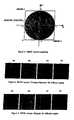
- Thiscan be envisioned as a distribution of normal direction vectors in the upper hemisphere of a hypothetical spherical model, as illustrated in FIG. 2.
- the distribution of vectorsrepresents the surface characteristics and geometry of the surface being modeled with the BRDF model.
- the distribution of normal direction vectors for a given type of surfacecan be obtained on the basis of selected, conventionally available BDRF surface models.
- a BRDF surface model for a flat, reflective surface made of brushed metalwill have a certain characteristic (anisotropic) distribution of normal direction vectors (in terms of magnitude and direction).
- a BRDF model of a curved, high reflective smooth surfacewill have a quite different (isotropic) distribution of normal direction vectors.
- a BRDF texture map of the surface of the objectis carried out by evaluation of diffuse and specular components.
- the computation of BRDF valuesis a 4D (four dimensional) function for each wavelength, so it is a mapping of a 5D function into a 3D space in the case of R, G, B lighting model.
- a 2D texture map in spherical coordinatesis used to represent the 5D BDRF function.
- the 2D texture mapcan be thought of as BRDF values for a distribution of normal direction vectors in the upper hemisphere representing a range of surface points, as illustrated in FIG. 2.
- the distribution of normal direction vectors determined for a given surface characteristic and geometryare sampled in discrete angular increments over the given range sufficient for a desired level of visual resolution.
- the normal direction vectorsare also normalized to a given unit image size, for example, in the interval [-1,1], as illustrated in FIG. 3.
- the BRDF function parametersare derived in terms of the incoming light vector L, the view vector V, and the normal direction vectors N .
- the actual computation of BRDF valuesis then done by using the derived function parameters and a mathematical model for the light reflectance function.
- Conventional light reflectance functionssuch as Torrance-Sparrow, Phong, Strauss, etc., may be used.
- the diffuse component of the BRDF valuescan be assumed to be lambertian and unaffected by surface geometry attenuation or microfacet distribution.
- a modified approachmay also be used, referred to as Schlick, which takes into account the surface characteristics for both diffuse and specular components. This approach is found to give better visual results and is faster for computation than the conventional BRDF models. It combines the diffuse and specular components by multiplying one by the other, instead of summing them.
- the computed values for the BRDF light reflectance texture mapis stored as a lookup table indexed to the discretized increments of normal directions.
- a BRDF texture mapis computed for each object surface, direction of light source, and direction of viewing in a scene. If the object's surface normals do not change from frame to frame, then the BRDF values remain unchanged. Thus, for a non-deforming object, there is no need to recompute the BRDF texture map for every frame.
- the BRDF texture mapsare stored as part of the scene data for a CG program.
- the BRDF value for any point on the surface of an object in a sceneis retrieved based upon the normal direction vector specified for that point in the scene, and used to derive the shading value for the associated light source in the scene.
- Examples of the shading results for 4 views of a spherical surface based on the Torrance-Sparrow modelare illustrated in FIGS. 4A-4D, and 4 views based upon the Schlick model are illustrated in FIGS. 7A-7D.
- the surface of the objectmay be without other surface texture characteristics, such as a smooth surface, or may be a highly textured surface, such as a face textured with hair and features like eyebrows and lips.
- the specular componentcan be mapped on the surface in one pass. Examples of the shading results for an untextured face mapped with conventional BRDF are illustrated in FIGS. 5A and 5B. If the object is textured, its surface diffuses color, so both the diffuse and specular components of the BRDF texture map are used. In the conventional BRDF model, the diffuse component is considered lambertian, and can be incorporated in the hardware performance of the illumination process by using a diffusion coefficient.
- the diffuse componentis combined with the texture of the object's surface on a first pass, and the specular component is added to the shading on a second pass. Examples of the shading results for a textured face mapped with conventional BRDF is illustrated in FIGS. 6A and 6B.
- a logic diagramillustrates the overall process steps in the preferred implementation of the invention.
- the surface characteristics and geometry of an object in a sceneare determined, as indicated at block 101.
- a distribution of normal direction vectors N for the objectis determined, relative to the light direction L and view direction V in the scene, at block 102.
- the particular BRDF light reflectance model to be usedis selected depending upon the type of surface, at block 103.
- the BRDF function parametersare computed based upon the parameters of the light direction L, view direction V, and normal direction vectors N for the object, at block 104.
- the BRDF valuesare computed and stored as a texture map for the object surface in the scene, at block 105, and retained as scene data awaiting the beginning of real-time rendering, as indicated at block 106, e.g., upon initialization of a CG video game or movie.
- a "World Task" for a sceneis generated, defining each frame of the scene and its objects and illumination sources, and for each frame the shading function is called, as indicated at block 107.
- the shading functioncomputes the surface light and color reflected from the illumination sources at each point on an object's surface in the scene.
- the surface characteristic and color properties of the object stored with the scene dataare retrieved.
- the light reflected at each point from light sources in the sceneis computed.
- the stored BRDF texture mapis applied to compute the light reflectance values for the points on the object's surface.
- shadingproceeds in 2 passes, adding a diffuse component and a spectral component, as indicated at block 109.
- shadingproceeds in 3 passes, first shading the surface texture features, and blending a diffuse-dominant component and then a spectral-dominant component, as indicated at block 110.
- the inventionprovides an improved surface shading technique for real-time CG rendering in which a physical light reflectance texture map is computed and stored during the CG development phase, then later applied during the real-time rendering phase.
- This approachallows the rich texturing of a physical light reflectance model, such as conventional BRDF models or a modified Schlick BRDF model, to be used for shading in real-time rendering.
- the BRDF texture mapcan be applied to any arbitrary geometry as long as the vertices of the microfacets on the surface of the object are available.
- This approachis well suited for real-time rendering using conventional hardware and multipass shading techniques, and also allows BRDF texture map to be used in combination with textured surfaces such as skin.
Landscapes
- Engineering & Computer Science (AREA)
- Computer Graphics (AREA)
- Physics & Mathematics (AREA)
- General Physics & Mathematics (AREA)
- Theoretical Computer Science (AREA)
- Image Generation (AREA)
Abstract
Description
This patent application claims the priority of U.S. Provisional Application60/244,040 filed on October 26, 2000, entitled "Microfacet Based Texture Map Using BidirectionalReflectance Distribution Function", by the same inventor.
This invention relates to the field of computer graphics and, in particular, to animproved method for CG surface shading using a stored texture map for faster processing.
Computer graphics (CG) systems create display images frame-by-frame from digitaldata representing mathematically-described objects in a scene. CG systems have been noteworthyrecently in creating computer-generated special effects, animated films, interactive 3D video games,and other interactive or 3D effects in digital media. They are widely used for entertainment andadvertising, computer aided design, flight simulation and training, and many other applications.
In advanced CG applications, a CG development platform is used to create an overallCG media program and accompanying database of scenes and objects, such as the MAYA™development platform offered by Alias Wavefront, Inc., of Toronto, Ontario, Canada, which is asubsidiary of Silicon Graphics, Inc. The MAYA™ development platform is a 3D modeling,animation, and rendering software package that has advanced interface, workflow, flexibility, anddepth features. MAYA includes many tools used for modeling and animation, including settingkeyframes and constraints, inverse kinematics, attaching surfaces to skeletons, character modeling,nurbs modeling, character expressions, particle and dynamics suites for rigid and soft bodies,texturing, and tools for rendering including node-based shaders, anti-aliasing, motion blur, and selective raytracing/raycasting. At the heart of MAYA is MEL, its scripting language. Everyaction, every part of the interface, and every tool is invoked and described by MEL. It is, therefore,possible to create new tools, combinations of tools, completely modify the interface, and tie MAYAin with other software programs using MEL. Further information about the MAYA™ developmentplatform can be obtained from "MAYA Software Rendering: A Technical Overview", by AndrewPierce and Kelvin Sung, published by Alias/Wavefront, 1998, 2000,
The developed CG media program and data files, referred to as "SHOT" data files,can then be rendered into a visual display of the CG media program. The rendering processoperates on a "World Task" which includes many different rendering tasks. The many renderingtasks include many independent operations which lend themselves to efficiencies obtained byparallel processing using multiple CPUs. One renderer capable of doing this is theRENDERMAN™ renderer developed by Pixar Animation Studios of Emeryville, CA.
However, even with advanced CG systems, the computational intensity of renderingand the large data size of visually rich CG scenes can impose a high computational burden thatrequires that compromises be made in terms of image quality. For example, the light/color shadingof surfaces of objects in an image scene typically requires computing the surface texture for eachpoint on an object's surface from stored surface characteristic data, then computing the lightreflectance characteristic of each such point according to a selected light reflectance model, thencomputing the reflected light values (typically, its specular and diffuse components) from each suchpoint by applying a light vector from each illumination source (emitted, ambient, diffuse, andspecular light) in the scene. Among the different light reflectance models that may be used, theones based upon the physics of light interaction with surface material characteristics, for example,the bidirectional reflectance distribution function (BDRF), are the most accurate in terms ofrendering quality, but among the most expensive (intensive) to compute. As a result, surfaceshading using a physical light reflectance model such as BRDF has been precluded from use in real-timerendering engines.
Accordingly, it is a principal object of the present invention to provide an improvedmethod for CG surface shading that would allow the use of a physical light reflectance model in real-time CG rendering. It is a particular object of the invention to utilize the bidirectionalreflectance distribution function as a physical light reflectance model in real-time CG rendering.
In accordance with the present invention, an improved method for computer graphics(CG) surface shading comprises:
The invention technique employs a selected BRDF model during development of aCG program to compute light reflectance values for a sampled range of normal direction vectors asa texture map to be used later during rendering, The BRDF model is applied with a standard modelfor distribution of normal direction vectors for a given type of surface, and the BRDF values arecomputed and stored as a look-up table indexed to the sampled range of normal direction vectors.During real-time rendering, surface shading can be readily processed by using the normal directionvector for any given point to look up the stored BRDF value. Shading with BRDF light reflectancevalues can be combined in one or more passes with shading of other surface texture characteristics, e.g., a facial skin surface textured with hair and facial features. In this manner, the rich tones of aphysical light reflectance model can be obtained even for highly textured surfaces during real-timerendering. Besides standard types of light reflectance models (Torrance-Sparrow, Phong, Strauss,etc.), modified types of BRDF models (e.g., Schlick) may also be used to derive a BRDF texturemap.
Other objects, features, and advantages of the present invention will be described infurther detail below, with reference to the following drawings:
A preferred implementation of the improved method of surface shading inaccordance with the present invention is described in detail below using the example of a physicallight reflectance model for interaction of light with a textured surface. However, it is to beunderstood that the general principles of the invention have broad applicability to renderinginvolving other types of surface texture characteristics and physical light reflectance models as well.
Surface shading of objects in an image scene is conventionally accomplished duringrendering by computing the surface texture characteristics for each point on an object's surface fromstored surface characteristic and geometry parameters and then computing the light reflectancevalue from that point. The reflected light for each point is computed based upon the variousincoming sources of illumination (emitted, ambient, diffuse, and specular light) on the object. Forfurther information about light illumination and reflection in conventional surface shading,reference is made to "Lighting", Chapter 6, from "Open GL programming Guide", SiliconGraphics, Inc., published by Addison-Wesley Publishing Company.
In conventional CG techniques, the surface of an object can be envisioned as a set ofmicrofacet mirrors that are wrapped over the contour of an object (spherical, ovoid, flat, etc.). Themicrofacets can have varying orientations (represented by their normal direction vectors) at theminute local level and can result in complex light reflection paths reflecting from a number ofmicrofacets in a complex scattering of light in the vicinity of an observed point. This complex light scattering provides a surface with its characteristic light reflectance "texture". Modeling the lightreflectance texture of a surface can provide a viewer with a more richly rendered image of thesurface, as contrasted, for example, to a simple model of a shiny surface with a spot reflection.However, computation of the complex light scattering from microfacets for each point on thesurface of the object would be an enormously time-consuming, if not impossible, task for real-timerendering.
Computing light reflectance can be simplified somewhat using the notion ofBidirectional Reflectance Distribution Function (BRDF) and BRDF lighting techniques. In theBRDF concept, the complex light interactions from microfacets at the minute local level areignored, and instead the light reflectance for a point on a surface are modeled on the basis ofincoming light direction to a point, outgoing light direction (eye view direction) from the point, andthe wavelength of light. BRDF can thus be written as a function of light direction vectors andparameters in terms of spherical coordinate geometery rather than cartesian coordinates. The lightreflectance values returned for the BRDF function can be derived by evaluating mathematicalfunctions approximating analytical light reflectance models or by sampling empirical measurementsof real-world surfaces.
Conventional analytical models have been developed that generate a wide range ofvisually interesting light reflectance effects, including the Cook-Torrance, Torrance-Sparrow,Phong, Ward, Strauss, and other models. In general, different models are useful in modeling thelight reflectance characteristics of different types of materials. For example, the Ward model isgood at modeling the reflectance properties of anisotropic surfaces, such as brushed metal. TheCook-Torrance model is effective at simulating many types of reflective metal, such as copper andgold, and plastics with varying degrees of roughness. In contrast to analytical models, BRDFvalues can also be acquired through physical measurements with measuring devices like agonioreflectometer. Acquired BRDF values for many different types of surfaces are available fromlibraries of several academic institutions and commercial companies. For further details, referenceis made to the article entitled "Introduction to BRDF-Based Lighting", by Chris Wynn, publishedby Nvidia Corporation, 2000.
While BRDF models have been proposed as a useful way to derive light reflectancevalues instead of computing complex light scattering from different types of surfaces, they are notwidely used in real-time CG rendering because they are still too computationally intensive forconventional computer graphics hardware in widespread use.
In the present invention, a selected BRDF function is used to generate a lightreflectance texture map during development of a CG program and stored for later use during real-timerendering. The texture map is stored as a look-up table of light reflectance values indexed tonormal direction vectors over a sampled range of spherical coordinates. During rendering, theobject's surface is shaded by retrieving the stored light reflectance value for the correspondingnormal direction vector ascribed to the point on the surface. In this manner, the richness of theBRDF modeling of light reflectance from a surface can be incorporated in surface shading, withoutthe computational cost of using the BRDF model during real-time rendering. This approach is wellsuited to the demands of real-time rendering using conventional hardware and standard multipassrendering techniques. It is particularly advantageous for shading textured surfaces, such as thehuman face. An example of the application of a BRDF texture map to surface shading inaccordance with the invention is described below. A detailed explanation of the mathematics ofBRDF texture map is provided in the accompanyingAppendix A.
FIG. 1 illustrates the BRDF model that is used for creating a light reflectance texturemap during development of a CG program. The BRDF model can be thought of in terms of anincoming light direction represented by the negative of light vectorL, an outgoing light directionrepresented by the eye view vectorV, a normal direction vectorN representing the orientation of thesurface at the pointP, and a surface tangent vectorT and surface normal vectorB defining thesurface around the point P. The vectors are defined in spherical coordinates in terms of theircorresponding surface projections and angles relative to the normal direction vector of the point Pbeing sampled.
In the invention, complex light scattering analysis for each point on the surface of anobject is ignored. Instead, a global light reflectance texture map is generated for a distribution ofnormal direction vectors representing the range of orientations of points on the surface of the object being modeled. This can be envisioned as a distribution of normal direction vectors in the upperhemisphere of a hypothetical spherical model, as illustrated inFIG. 2. The distribution of vectorsrepresents the surface characteristics and geometry of the surface being modeled with the BRDFmodel. As mentioned previously, the distribution of normal direction vectors for a given type ofsurface can be obtained on the basis of selected, conventionally available BDRF surface models.For example, a BRDF surface model for a flat, reflective surface made of brushed metal will have acertain characteristic (anisotropic) distribution of normal direction vectors (in terms of magnitudeand direction). A BRDF model of a curved, high reflective smooth surface will have a quitedifferent (isotropic) distribution of normal direction vectors.
A BRDF texture map of the surface of the object is carried out by evaluation ofdiffuse and specular components. The computation of BRDF values is a 4D (four dimensional)function for each wavelength, so it is a mapping of a 5D function into a 3D space in the case of R,G, B lighting model. A 2D texture map in spherical coordinates is used to represent the 5D BDRFfunction. The 2D texture map can be thought of as BRDF values for a distribution of normaldirection vectors in the upper hemisphere representing a range of surface points, as illustrated inFIG. 2. The distribution of normal direction vectors determined for a given surface characteristicand geometry are sampled in discrete angular increments over the given range sufficient for adesired level of visual resolution. The normal direction vectors are also normalized to a given unitimage size, for example, in the interval [-1,1], as illustrated inFIG. 3.
The BRDF function parameters (magnitudes and angles) are derived in terms of theincoming light vectorL, the view vectorV, and the normal direction vectorsN. The actualcomputation of BRDF values is then done by using the derived function parameters and amathematical model for the light reflectance function. Conventional light reflectance functions,such as Torrance-Sparrow, Phong, Strauss, etc., may be used. In these approaches, the diffusecomponent of the BRDF values can be assumed to be lambertian and unaffected by surfacegeometry attenuation or microfacet distribution. A modified approach may also be used, referred toas Schlick, which takes into account the surface characteristics for both diffuse and specularcomponents. This approach is found to give better visual results and is faster for computation than the conventional BRDF models. It combines the diffuse and specular components by multiplyingone by the other, instead of summing them.
The computed values for the BRDF light reflectance texture map is stored as alookup table indexed to the discretized increments of normal directions. A BRDF texture map iscomputed for each object surface, direction of light source, and direction of viewing in a scene. Ifthe object's surface normals do not change from frame to frame, then the BRDF values remainunchanged. Thus, for a non-deforming object, there is no need to recompute the BRDF texture mapfor every frame. The BRDF texture maps are stored as part of the scene data for a CG program.During real-time rendering, the BRDF value for any point on the surface of an object in a scene isretrieved based upon the normal direction vector specified for that point in the scene, and used toderive the shading value for the associated light source in the scene. Examples of the shadingresults for 4 views of a spherical surface based on the Torrance-Sparrow model are illustrated inFIGS. 4A-4D, and 4 views based upon the Schlick model are illustrated inFIGS. 7A-7D.
The surface of the object may be without other surface texture characteristics, suchas a smooth surface, or may be a highly textured surface, such as a face textured with hair andfeatures like eyebrows and lips. In a surface without texture, and using the conventional BRDFmodel, the specular component can be mapped on the surface in one pass. Examples of the shadingresults for an untextured face mapped with conventional BRDF are illustrated inFIGS. 5A and 5B.If the object is textured, its surface diffuses color, so both the diffuse and specular components ofthe BRDF texture map are used. In the conventional BRDF model, the diffuse component isconsidered lambertian, and can be incorporated in the hardware performance of the illuminationprocess by using a diffusion coefficient. The diffuse component is combined with the texture of theobject's surface on a first pass, and the specular component is added to the shading on a second pass.Examples of the shading results for a textured face mapped with conventional BRDF is illustrated inFIGS. 6A and 6B.
In the modified Schlick BRDF model, two texture map values are used, one with thediffuse component dominant, and the other with the specular component dominant. If the surface iswithout texture, only one BRDF texture combining diffuse and specular components is used in one pass (Surface Type Single). Examples of the shading results for an untextured face mapped withSchlick BRDF are illustrated inFIGS. 8A and 8B. If the surface is textured, shading proceeds inthree passes. In the first pass, the object is drawn with its surface texture but without illumination.In the second pass, the diffuse dominant BRDF texture is blended with the result of the first pass,and in the third pass, the specular dominant BRDF texture is blended (Surface Type Double).Examples of the shading results for a textured face mapped with Schlick BRDF are illustrated inFIGS. 9A and 9B.
Referring toFIG. 10, a logic diagram illustrates the overall process steps in thepreferred implementation of the invention. During development of a CG program, the surfacecharacteristics and geometry of an object in a scene are determined, as indicated at block 101.Based upon the surface characteristics and geometry, a distribution of normal direction vectors Nfor the object is determined, relative to the light direction L and view direction V in the scene, atblock 102. The particular BRDF light reflectance model to be used is selected depending upon thetype of surface, atblock 103. The BRDF function parameters are computed based upon theparameters of the light direction L, view direction V, and normal direction vectors N for the object,atblock 104. Using the computed function parameters and BRDF model, the BRDF values arecomputed and stored as a texture map for the object surface in the scene, atblock 105, and retainedas scene data awaiting the beginning of real-time rendering, as indicated atblock 106, e.g., uponinitialization of a CG video game or movie.
During real-time rendering, a "World Task" for a scene is generated, defining eachframe of the scene and its objects and illumination sources, and for each frame the shading functionis called, as indicated atblock 107. For a typical shading task, the shading function computes thesurface light and color reflected from the illumination sources at each point on an object's surface inthe scene. First, the surface characteristic and color properties of the object stored with the scenedata are retrieved. Then the light reflected at each point from light sources in the scene is computed.As indicated atblock 108, the stored BRDF texture map is applied to compute the light reflectancevalues for the points on the object's surface. With the conventional BRDF model, shading proceedsin 2 passes, adding a diffuse component and a spectral component, as indicated atblock 109. Withthe Schlick BRDF model, shading proceeds in 3 passes, first shading the surface texture features, and blending a diffuse-dominant component and then a spectral-dominant component, as indicatedat block 110.
In summary, the invention provides an improved surface shading technique for real-timeCG rendering in which a physical light reflectance texture map is computed and stored duringthe CG development phase, then later applied during the real-time rendering phase. This approachallows the rich texturing of a physical light reflectance model, such as conventional BRDF modelsor a modified Schlick BRDF model, to be used for shading in real-time rendering. The BRDFtexture map can be applied to any arbitrary geometry as long as the vertices of the microfacets onthe surface of the object are available. This approach is well suited for real-time rendering usingconventional hardware and multipass shading techniques, and also allows BRDF texture map to beused in combination with textured surfaces such as skin.
It is understood that many other modifications and variations may be devised giventhe above description of the principles of the invention. It is intended that all such modificationsand variations be considered as within the spirit and scope of this invention, as defined in thefollowing claims.


Claims (8)
- An improved method for surface shading comprising:(a) determining surface characteristics and geometry parameters of a surface of anobject in a scene during development of a computer graphics (CG) program;(b) determining for a frame of the scene an incoming light direction illuminating thesurface of the object and an outgoing direction of viewing the object in the scene;(c) applying a selected bidirectional reflectance distribution function (BRDF) modelto compute light reflectance values for a sampling of a distribution of normaldirection vectors for light reflectance from the surface of the object in the frameof the scene based upon the incoming and outgoing light directions and thesurface characteristics and geometry parameters of the surface of the object;(d) storing the sampled BADE values as a texture map of light reflectance for surfaceshading of the object in the frame of the scene; and(e) performing surface shading of the object during real-time rendering by applyingthe sampled BRDF values in correspondence to normal direction vectors forpoints on the surface of the object in the frame of the scene.
- An improved surface shading method according to Claim 1, wherein thedistribution of normal direction vectors is based upon a standard model for physical lightreflectance from a given type of surface.
- An improved surface shading method according to Claim 2, wherein the samplingof the distribution of normal direction vectors is taken in discrete increments of normal directionvectors for an upper hemispherical space normalized to a unit image size.
- An improved surface shading method according to Claim 1, wherein the BRDFmodel is a conventional one selected from the group consisting of: Torrance-Sparrow model; Phongmodel, and Strauss model.
- An improved surface shading method according to Claim 1, wherein the BRDFmodel is a modified Schlick model.
- An improved surface shading method according to Claim 1, wherein the BRDFvalues are stored as a look up table indexed to the sampling of normal direction vectors.
- An improved surface shading method according to Claim 1, wherein the surfaceof the object is without other surface texture characteristics, and the surface shading for physicallight reflectance is performed in one pass.
- An improved surface shading method according to Claim 1, wherein the surfaceof the object is textured with other surface texture characteristics, and the surface shading forphysical light reflectance is combined with shading for other surface texture characteristics in twoor more other passes.
Applications Claiming Priority (4)
| Application Number | Priority Date | Filing Date | Title |
|---|---|---|---|
| US24404000P | 2000-10-26 | 2000-10-26 | |
| US244040P | 2000-10-26 | ||
| US899802 | 2001-07-06 | ||
| US09/899,802US6765573B2 (en) | 2000-10-26 | 2001-07-06 | Surface shading using stored texture map based on bidirectional reflectance distribution function |
Publications (2)
| Publication Number | Publication Date |
|---|---|
| EP1202222A2true EP1202222A2 (en) | 2002-05-02 |
| EP1202222A3 EP1202222A3 (en) | 2004-09-15 |
Family
ID=26936283
Family Applications (1)
| Application Number | Title | Priority Date | Filing Date |
|---|---|---|---|
| EP01125264AWithdrawnEP1202222A3 (en) | 2000-10-26 | 2001-10-24 | Method for surface shading using stored texture map |
Country Status (3)
| Country | Link |
|---|---|
| US (1) | US6765573B2 (en) |
| EP (1) | EP1202222A3 (en) |
| JP (2) | JP2002208031A (en) |
Cited By (6)
| Publication number | Priority date | Publication date | Assignee | Title |
|---|---|---|---|---|
| DE102004040372A1 (en)* | 2004-08-20 | 2006-03-09 | Diehl Avionik Systeme Gmbh | Method and device for displaying a three-dimensional topography |
| WO2008083206A3 (en)* | 2006-12-29 | 2008-12-04 | X Rite Inc | Surface appearance simulation |
| EP1826725A4 (en)* | 2004-11-22 | 2011-08-17 | Sony Computer Entertainment Inc | Plotting device and plotting method |
| CN102314704A (en)* | 2011-09-21 | 2012-01-11 | 北京航空航天大学 | BRDF (bidirectional reflectance distribution function) -based real-time subsurface scattering rendering method |
| CN104574492A (en)* | 2014-12-23 | 2015-04-29 | 福建天晴数码有限公司 | Real-time rendering method and device for object composed of multiple layers of materials |
| CN104700445B (en)* | 2015-03-23 | 2018-07-27 | 山东大学 | A kind of BRDF reflection model deriving methods based on measurement data |
Families Citing this family (65)
| Publication number | Priority date | Publication date | Assignee | Title |
|---|---|---|---|---|
| US7116333B1 (en)* | 2000-05-12 | 2006-10-03 | Microsoft Corporation | Data retrieval method and system |
| GB0109720D0 (en)* | 2001-04-20 | 2001-06-13 | Koninkl Philips Electronics Nv | Display apparatus and image encoded for display by such an apparatus |
| US7106325B2 (en)* | 2001-08-03 | 2006-09-12 | Hewlett-Packard Development Company, L.P. | System and method for rendering digital images having surface reflectance properties |
| US6753875B2 (en)* | 2001-08-03 | 2004-06-22 | Hewlett-Packard Development Company, L.P. | System and method for rendering a texture map utilizing an illumination modulation value |
| US6781594B2 (en)* | 2001-08-21 | 2004-08-24 | Sony Computer Entertainment America Inc. | Method for computing the intensity of specularly reflected light |
| WO2003032253A2 (en) | 2001-10-10 | 2003-04-17 | Sony Computer Entertainment America Inc. | System and method for environment mapping |
| US20040070565A1 (en)* | 2001-12-05 | 2004-04-15 | Nayar Shree K | Method and apparatus for displaying images |
| JP3962588B2 (en)* | 2002-01-07 | 2007-08-22 | キヤノン株式会社 | 3D image processing method, 3D image processing apparatus, 3D image processing system, and 3D image processing program |
| US7262770B2 (en)* | 2002-03-21 | 2007-08-28 | Microsoft Corporation | Graphics image rendering with radiance self-transfer for low-frequency lighting environments |
| US7075534B2 (en)* | 2002-06-21 | 2006-07-11 | Forrester Hardenbergh Cole | Method and system for automatically generating factored approximations for arbitrary bidirectional reflectance distribution functions |
| JP2006514266A (en)* | 2002-07-12 | 2006-04-27 | エレクトロ サイエンティフィック インダストリーズ インコーポレーテッド | Uniform light source method and apparatus |
| JP2004152015A (en)* | 2002-10-30 | 2004-05-27 | Digital Fashion Ltd | Image processing apparatus, image processing program, recording medium for recording the program, image processing method, shading information acquisition apparatus, and data structure |
| US20040169656A1 (en)* | 2002-11-15 | 2004-09-02 | David Piponi Daniele Paolo | Method for motion simulation of an articulated figure using animation input |
| US7616802B2 (en) | 2003-03-06 | 2009-11-10 | Digital Media Professionals, Inc. | Light reflection intensity calculation circuit |
| WO2005015490A2 (en)* | 2003-07-02 | 2005-02-17 | Trustees Of Columbia University In The City Of New York | Methods and systems for compensating an image projected onto a surface having spatially varying photometric properties |
| US8133115B2 (en) | 2003-10-22 | 2012-03-13 | Sony Computer Entertainment America Llc | System and method for recording and displaying a graphical path in a video game |
| WO2005124691A1 (en)* | 2004-06-16 | 2005-12-29 | Techno Dream 21 Co., Ltd. | Method of real-time rendering performed by sampling reflection characteristics on an object surface and method for converting the texture size |
| US20060071933A1 (en) | 2004-10-06 | 2006-04-06 | Sony Computer Entertainment Inc. | Application binary interface for multi-pass shaders |
| US7614748B2 (en)* | 2004-10-25 | 2009-11-10 | The Trustees Of Columbia University In The City Of New York | Systems and methods for displaying three-dimensional images |
| JP4282587B2 (en)* | 2004-11-16 | 2009-06-24 | 株式会社東芝 | Texture mapping device |
| KR100609145B1 (en)* | 2004-12-20 | 2006-08-08 | 한국전자통신연구원 | Rendering device and its method for real-time global lighting effect |
| US7944561B2 (en)* | 2005-04-25 | 2011-05-17 | X-Rite, Inc. | Measuring an appearance property of a surface using a bidirectional reflectance distribution function |
| CN100554944C (en)* | 2005-04-30 | 2009-10-28 | 中国科学院安徽光学精密机械研究所 | Laboratory smoke (water) mist BRDF measuring method |
| US7636126B2 (en) | 2005-06-22 | 2009-12-22 | Sony Computer Entertainment Inc. | Delay matching in audio/video systems |
| JP2007026049A (en)* | 2005-07-15 | 2007-02-01 | Ritsumeikan | Image processing device using reference anisotropic reflection distribution, image processing program, recording medium for recording program, and image processing method |
| JP4693555B2 (en)* | 2005-09-02 | 2011-06-01 | 大日本印刷株式会社 | Two-dimensional image generation method and generation apparatus based on a three-dimensional virtual object with a fiber sheet attached to the surface |
| RU2295772C1 (en)* | 2005-09-26 | 2007-03-20 | Пензенский государственный университет (ПГУ) | Method for generation of texture in real time scale and device for its realization |
| JP2007257079A (en)* | 2006-03-20 | 2007-10-04 | Digital Fashion Ltd | Texture generation program, texture generation device, and texture generation method |
| US7880746B2 (en) | 2006-05-04 | 2011-02-01 | Sony Computer Entertainment Inc. | Bandwidth management through lighting control of a user environment via a display device |
| US7965859B2 (en) | 2006-05-04 | 2011-06-21 | Sony Computer Entertainment Inc. | Lighting control of a user environment via a display device |
| US7850195B2 (en)* | 2006-05-25 | 2010-12-14 | Simard Suspensions Inc. | Tandem suspension for steerable axles |
| US7990381B2 (en)* | 2006-08-31 | 2011-08-02 | Corel Corporation | Re-coloring a color image |
| US20090046099A1 (en)* | 2006-11-13 | 2009-02-19 | Bunkspeed | Real-time display system |
| US20080117215A1 (en)* | 2006-11-20 | 2008-05-22 | Lucasfilm Entertainment Company Ltd | Providing A Model With Surface Features |
| JP5059503B2 (en)* | 2007-07-13 | 2012-10-24 | 花王株式会社 | Image composition apparatus, image composition method, and image composition program |
| US7929142B2 (en)* | 2007-09-25 | 2011-04-19 | Microsoft Corporation | Photodiode-based bi-directional reflectance distribution function (BRDF) measurement |
| US20090167762A1 (en)* | 2007-12-26 | 2009-07-02 | Ofer Alon | System and Method for Creating Shaders Via Reference Image Sampling |
| US7796727B1 (en) | 2008-03-26 | 2010-09-14 | Tsi, Incorporated | Aerosol charge conditioner |
| KR101582607B1 (en)* | 2009-04-30 | 2016-01-19 | 삼성전자주식회사 | Semiconductor memory device |
| US9098945B2 (en)* | 2009-05-01 | 2015-08-04 | Microsoft Technology Licensing, Llc | Modeling anisotropic surface reflectance with microfacet synthesis |
| KR20110053166A (en) | 2009-11-13 | 2011-05-19 | 삼성전자주식회사 | 3D object rendering method and apparatus |
| KR101284794B1 (en)* | 2009-12-21 | 2013-07-10 | 한국전자통신연구원 | Apparatus and method for fabric objects rendering |
| US8248613B2 (en) | 2010-04-29 | 2012-08-21 | Microsoft Corporation | Capturing reflected light from a sampling surface |
| US10786736B2 (en) | 2010-05-11 | 2020-09-29 | Sony Interactive Entertainment LLC | Placement of user information in a game space |
| CN101882323B (en)* | 2010-05-19 | 2012-06-13 | 北京航空航天大学 | Microstructure surface global illumination real-time rendering method based on height map |
| US9684975B2 (en)* | 2011-02-18 | 2017-06-20 | Take-Two Interactive Software, Inc. | Method and system for filtering of visual objects |
| US9342817B2 (en) | 2011-07-07 | 2016-05-17 | Sony Interactive Entertainment LLC | Auto-creating groups for sharing photos |
| US9275477B2 (en)* | 2011-12-05 | 2016-03-01 | Kabushiki Kaisha Square Enix | Real-time global illumination rendering system |
| US20140028801A1 (en)* | 2012-07-30 | 2014-01-30 | Canon Kabushiki Kaisha | Multispectral Binary Coded Projection |
| US9153065B2 (en) | 2013-02-05 | 2015-10-06 | Google Technology Holdings LLC | System and method for adjusting image pixel color to create a parallax depth effect |
| US9947132B2 (en)* | 2013-03-15 | 2018-04-17 | Nvidia Corporation | Material representation data structure and method of representing a material for digital image synthesis |
| US9965893B2 (en)* | 2013-06-25 | 2018-05-08 | Google Llc. | Curvature-driven normal interpolation for shading applications |
| KR101526487B1 (en)* | 2013-07-24 | 2015-06-10 | 디게이트 주식회사 | Apparatus for rendering 3D object |
| JP6087301B2 (en)* | 2014-02-13 | 2017-03-01 | 株式会社ジオ技術研究所 | 3D map display system |
| EP3057067B1 (en)* | 2015-02-16 | 2017-08-23 | Thomson Licensing | Device and method for estimating a glossy part of radiation |
| JP6604744B2 (en)* | 2015-05-03 | 2019-11-13 | キヤノン株式会社 | Image processing apparatus, image processing method, image forming system, and program |
| US10504273B2 (en) | 2016-12-09 | 2019-12-10 | Nvidia Corporation | Automatic level-of-detail for physically-based materials |
| DE102017127367A1 (en) | 2016-12-09 | 2018-06-14 | Nvidia Corporation | AUTOMATIC DETAILED GRADE FOR PHYSICALLY BASED MATERIALS |
| US20180268614A1 (en)* | 2017-03-16 | 2018-09-20 | General Electric Company | Systems and methods for aligning pmi object on a model |
| US10926176B1 (en)* | 2017-03-28 | 2021-02-23 | Kabam, Inc. | Physics engine using depth information |
| US10636201B2 (en)* | 2017-05-05 | 2020-04-28 | Disney Enterprises, Inc. | Real-time rendering with compressed animated light fields |
| GB2586060B (en)* | 2019-08-01 | 2022-09-21 | Sony Interactive Entertainment Inc | Surface characterisation apparatus and system |
| CN111586444B (en)* | 2020-06-05 | 2022-03-15 | 广州繁星互娱信息科技有限公司 | Video processing method and device, electronic equipment and storage medium |
| CN114937116B (en)* | 2022-02-16 | 2025-08-22 | 上海金角鱼软件有限公司 | Motion blur special effects rendering method for high-speed rotation |
| EP4235149A1 (en)* | 2022-02-23 | 2023-08-30 | Carl Zeiss Vision International GmbH | Computer-implemented method, computer program, data processing system and device for determining the reflectance properties of a surface of an object, and storage medium having instructions stored thereon for determining the reflectance properties of a surface of an object |
Family Cites Families (5)
| Publication number | Priority date | Publication date | Assignee | Title |
|---|---|---|---|---|
| US4991971A (en)* | 1989-02-13 | 1991-02-12 | United Technologies Corporation | Fiber optic scatterometer for measuring optical surface roughness |
| JPH11175752A (en)* | 1997-12-15 | 1999-07-02 | Sega Enterp Ltd | Image processing apparatus and image processing method |
| JPH11195138A (en)* | 1998-01-06 | 1999-07-21 | Sharp Corp | Image processing device |
| US6552726B2 (en)* | 1998-07-17 | 2003-04-22 | Intel Corporation | System and method for fast phong shading |
| AU2001292559A1 (en)* | 2000-08-24 | 2002-03-04 | Immersive Technologies Llc | Computerized image system |
- 2001
- 2001-07-06USUS09/899,802patent/US6765573B2/ennot_activeExpired - Lifetime
- 2001-10-24EPEP01125264Apatent/EP1202222A3/ennot_activeWithdrawn
- 2001-10-26JPJP2001329764Apatent/JP2002208031A/enactivePending
- 2001-10-26JPJP2001329763Apatent/JP2002236938A/enactivePending
Cited By (10)
| Publication number | Priority date | Publication date | Assignee | Title |
|---|---|---|---|---|
| DE102004040372A1 (en)* | 2004-08-20 | 2006-03-09 | Diehl Avionik Systeme Gmbh | Method and device for displaying a three-dimensional topography |
| DE102004040372B4 (en)* | 2004-08-20 | 2006-06-29 | Diehl Avionik Systeme Gmbh | Method and device for displaying a three-dimensional topography |
| EP1628262A3 (en)* | 2004-08-20 | 2010-08-04 | Diehl Aerospace GmbH | Method and Apparatus for rendering a threedimensional topography |
| EP1826725A4 (en)* | 2004-11-22 | 2011-08-17 | Sony Computer Entertainment Inc | Plotting device and plotting method |
| WO2008083206A3 (en)* | 2006-12-29 | 2008-12-04 | X Rite Inc | Surface appearance simulation |
| US9767599B2 (en) | 2006-12-29 | 2017-09-19 | X-Rite Inc. | Surface appearance simulation |
| CN102314704A (en)* | 2011-09-21 | 2012-01-11 | 北京航空航天大学 | BRDF (bidirectional reflectance distribution function) -based real-time subsurface scattering rendering method |
| CN102314704B (en)* | 2011-09-21 | 2013-03-20 | 北京航空航天大学 | BRDF (bidirectional reflectance distribution function) -based real-time subsurface scattering rendering method |
| CN104574492A (en)* | 2014-12-23 | 2015-04-29 | 福建天晴数码有限公司 | Real-time rendering method and device for object composed of multiple layers of materials |
| CN104700445B (en)* | 2015-03-23 | 2018-07-27 | 山东大学 | A kind of BRDF reflection model deriving methods based on measurement data |
Also Published As
| Publication number | Publication date |
|---|---|
| JP2002236938A (en) | 2002-08-23 |
| US20020080136A1 (en) | 2002-06-27 |
| EP1202222A3 (en) | 2004-09-15 |
| JP2002208031A (en) | 2002-07-26 |
| US6765573B2 (en) | 2004-07-20 |
Similar Documents
| Publication | Publication Date | Title |
|---|---|---|
| EP1202222A2 (en) | Method for surface shading using stored texture map | |
| US7212207B2 (en) | Method and apparatus for real-time global illumination incorporating stream processor based hybrid ray tracing | |
| Ward et al. | A survey on hair modeling: Styling, simulation, and rendering | |
| US6853377B2 (en) | System and method of improved calculation of diffusely reflected light | |
| US7106325B2 (en) | System and method for rendering digital images having surface reflectance properties | |
| Bastos et al. | Increased photorealism for interactive architectural walkthroughs | |
| Darsa et al. | Walkthroughs of complex environments using image-based simplification | |
| Drobot | Physically based area lights | |
| US7230620B2 (en) | Rendering deformable and animated surface reflectance fields | |
| Koster et al. | Real-time rendering of human hair using programmable graphics hardware | |
| JP3012828B2 (en) | Drawing method, apparatus, and recording medium | |
| Schwandt | High-Quality Illumination of Virtual Objects Based on an Environment Estimation in Mixed Reality Applications | |
| François et al. | Subsurface texture mapping | |
| Weyrich et al. | Rendering deformable surface reflectance fields | |
| AU2017228700A1 (en) | System and method of rendering a surface | |
| Kim | REAL-TIME RAY TRACING REFLECTIONS AND SHADOWS IMPLEMENTATION USING DIRECTX RAYTRACING | |
| JP7567528B2 (en) | Calculation device, calculation method and program | |
| Mao et al. | Automatic generation of hair texture with line integral convolution | |
| Kneiphof et al. | A Method for Fitting Measured Car Paints to a Game Engine's Rendering Model. | |
| Nadia | Cascaded Soft Shadow Maps Based On PCF Filtering | |
| Tao et al. | Real-Time Antialiased Area Lighting Using Multi-Scale Linearly Transformed Cosines. | |
| Klein et al. | Realreflect–real-time visualization of complex reflectance behaviour in virtual protoyping | |
| Jia | A Render Model For Particle System | |
| FOURNIER | in Computer Augmented Reality | |
| Kloetzli Jr | Real-Time Fur with Precomputed Radiance Transfer |
Legal Events
| Date | Code | Title | Description |
|---|---|---|---|
| PUAI | Public reference made under article 153(3) epc to a published international application that has entered the european phase | Free format text:ORIGINAL CODE: 0009012 | |
| AK | Designated contracting states | Kind code of ref document:A2 Designated state(s):AT BE CH CY DE DK ES FI FR GB GR IE IT LI LU MC NL PT SE TR | |
| AX | Request for extension of the european patent | Free format text:AL;LT;LV;MK;RO;SI | |
| RAP1 | Party data changed (applicant data changed or rights of an application transferred) | Owner name:KABUSHIKI KAISHA SQUARE ENIX | |
| PUAL | Search report despatched | Free format text:ORIGINAL CODE: 0009013 | |
| AK | Designated contracting states | Kind code of ref document:A3 Designated state(s):AT BE CH CY DE DK ES FI FR GB GR IE IT LI LU MC NL PT SE TR | |
| AX | Request for extension of the european patent | Extension state:AL LT LV MK RO SI | |
| 17P | Request for examination filed | Effective date:20050307 | |
| AKX | Designation fees paid | Designated state(s):DE FR GB | |
| 17Q | First examination report despatched | Effective date:20070920 | |
| STAA | Information on the status of an ep patent application or granted ep patent | Free format text:STATUS: THE APPLICATION IS DEEMED TO BE WITHDRAWN | |
| 18D | Application deemed to be withdrawn | Effective date:20080131 |