EP1200853B1 - Method and device for determining spatial positions and orientations - Google Patents
Method and device for determining spatial positions and orientationsDownload PDFInfo
- Publication number
- EP1200853B1 EP1200853B1EP00943508AEP00943508AEP1200853B1EP 1200853 B1EP1200853 B1EP 1200853B1EP 00943508 AEP00943508 AEP 00943508AEP 00943508 AEP00943508 AEP 00943508AEP 1200853 B1EP1200853 B1EP 1200853B1
- Authority
- EP
- European Patent Office
- Prior art keywords
- reflector
- laser beam
- measurement data
- respect
- angle
- Prior art date
- Legal status (The legal status is an assumption and is not a legal conclusion. Google has not performed a legal analysis and makes no representation as to the accuracy of the status listed.)
- Expired - Lifetime
Links
- 238000000034methodMethods0.000titleclaimsdescription34
- 238000005259measurementMethods0.000claimsabstractdescription86
- 230000003287optical effectEffects0.000claimsdescription17
- 230000000875corresponding effectEffects0.000claims2
- 230000002596correlated effectEffects0.000claims1
- 238000005305interferometryMethods0.000claims1
- 230000002093peripheral effectEffects0.000abstractdescription2
- 238000001514detection methodMethods0.000description2
- 239000000654additiveSubstances0.000description1
- 230000000996additive effectEffects0.000description1
- 230000009286beneficial effectEffects0.000description1
- 230000005540biological transmissionEffects0.000description1
- 230000001419dependent effectEffects0.000description1
- 238000010586diagramMethods0.000description1
- 238000003384imaging methodMethods0.000description1
Images


Classifications
- G—PHYSICS
- G01—MEASURING; TESTING
- G01S—RADIO DIRECTION-FINDING; RADIO NAVIGATION; DETERMINING DISTANCE OR VELOCITY BY USE OF RADIO WAVES; LOCATING OR PRESENCE-DETECTING BY USE OF THE REFLECTION OR RERADIATION OF RADIO WAVES; ANALOGOUS ARRANGEMENTS USING OTHER WAVES
- G01S17/00—Systems using the reflection or reradiation of electromagnetic waves other than radio waves, e.g. lidar systems
- G01S17/66—Tracking systems using electromagnetic waves other than radio waves
- G—PHYSICS
- G01—MEASURING; TESTING
- G01S—RADIO DIRECTION-FINDING; RADIO NAVIGATION; DETERMINING DISTANCE OR VELOCITY BY USE OF RADIO WAVES; LOCATING OR PRESENCE-DETECTING BY USE OF THE REFLECTION OR RERADIATION OF RADIO WAVES; ANALOGOUS ARRANGEMENTS USING OTHER WAVES
- G01S5/00—Position-fixing by co-ordinating two or more direction or position line determinations; Position-fixing by co-ordinating two or more distance determinations
- G01S5/16—Position-fixing by co-ordinating two or more direction or position line determinations; Position-fixing by co-ordinating two or more distance determinations using electromagnetic waves other than radio waves
- G01S5/163—Determination of attitude
Definitions
- the inventionis in the field of metrology and relates to a method and an arrangement according to the corresponding, independent patent claims. method and arrangement serve to determine the spatial position and orientation of objects, in particular of moving or movable objects.
- a spatial orientation of the reflector or objectIn addition to the position of the reflector or an object to which the reflector is arranged, also determines a spatial orientation of the reflector or object be, according to the state of the art on the object or on a suitably usable tool in addition to the above-mentioned reflector arranged more reflectors or points of light and is with, for example a digital camera whose optical axis is adapted to the laser beam direction is the arrangement of additional and illuminated reflectors or points of light displayed. From a comparison of the effective arrangement of the reflectors or points of light and the registered image of this arrangement may then have parameters the spatial orientation of the object (e.g., rotational positions with respect to orthogonal Axes) are calculated.
- the spatial orientation of the objecte.g., rotational positions with respect to orthogonal Axes
- the measuring systemalso includes an imaging device and an assembly may have further reflectors or points of light.
- an imaging deviceand an assembly may have further reflectors or points of light.
- the essential components of the applied laser trackerare a laser for Generation of the laser beam, an adjustable mirror device for aligning the Laser beam on the reflector and for tracking a moving reflector and an interferometer.
- cooperating reflectorsare common retroreflective triple prisms (prism with cube corner-shaped tip and for example, round base or front surface perpendicular to the axis of symmetry or optical axis of the prism) or optionally triple mirror (consisting from three mirrors assembled at right angles, the one hollow cube corner form).
- Such reflectorsreflect an incident parallel beam in regardless of the angle of incidence.
- the mentioned angle of incidence limitationaggravates those already mentioned above Measuring conditions, because the laser beam must not only for a measurement
- the front surface of the reflectorshould fall, but it must be in a fairly narrow angular range fall on this front surface.
- the reflectornot firmly on the moving object to attach, but two vertically Driven mutually driven axes to arrange pivoting and him for the measurements on the laser beam generated by the tracker always in such a way to align that the laser beam falls parallel to the optical axis in the reflector.
- the tip of the reflectorused triple mirror to design such that a specially generated Laser beam, which is directed to this tip area, is not reflected but passes through the reflector and arranged on a behind the reflector Position detector (e.g., PSD: position sensitive diode).
- PSDposition sensitive diode
- the inventionnow has the object, a method and an apparatus for Determination of position and orientation of in particular moving or movable Objects by means of a substantially stationary laser tracker and a To create reflector arranged on the object.
- Method and deviceshould simple, should be used in a variety of applications and should the mitigate the aforementioned limitations of such methods of determination as much as possible.
- Das.erfindungsgemässe methodis based on a reflector, which compared to the Object on which he is placed, a fixed, familiar position and orientation or a variable and measurable orientation and optionally has position, such that from the reflector position and from the reflector orientation not only on the object position but also on the object orientation can be closed.
- the processconsists essentially in in addition to measuring the direction of the laser beam and the interferometric Measurement of the path length of the laser beam and the angle of incidence of the laser beam in the reflector (orientation of the reflector relative to the laser beam) and / or the reflector orientation relative to the object to be measured and this Measurement data together with the measurement data for the laser beam direction and the interferometric certain measurement data for the calculation of the desired spatial position and to use orientation of the object.
- the measurement data resulting from the measurement of the angle of incidenceadvantageously become also used to when using a triple prism as a reflector the interferometric distance measurements and / or the angle measurements for Correct determination of the laser beam direction accordingly.
- the arrangement for carrying out the method according to the inventionhas a Laser tracker with means for measuring the path length of the laser beam (interferometer), a reflector mounted on the object with a relative to the object unchangeable, known position, a computer unit and means for transmission of Measurement data from the laser tracker to the computer unit.
- the reflectoris such mounted on the object, that its orientation relative to the object either unchangeable and known or changeable and can be detected by measurement.
- a triple prism used as a reflectorinstead of a tip on a passage surface, which is substantially parallel is aligned to its base surface so perpendicular to the optical axis and by the central part of the laser beam incident on the reflector, the prism left unreflective.
- On a triple mirror used as a reflectoris at the Tip provided a corresponding opening.
- Behind the reflectoris a position sensor arranged such that the partial beam passing through the reflector on it and the position of the light spot thrown on the sensor by the sub-beam directly depends on the direction of incidence of the laser beam in the reflector.
- the position sensoris, for example, in a plane perpendicular to the optical axis arranged the reflector and is for example a position senitive diode (PSD) or a CCD sensor (charge coupled device), as used in a digital camera for Application comes.
- PSDposition senitive diode
- CCDcharge coupled device
- From the detection of the passing through the reflector sub-beam with the position sensorcan rotate the reflector about two axes perpendicular to it be measured optical axis. Not detectable is a rotation around the optical Axis.
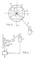
- FIG. 1shows very schematically an arrangement for carrying out the inventive method.
- This arrangementhas a laser tracker 1, a reflector 3 arranged on an object 2 and a computer unit 4.
- the laser trackeremits a laser beam 5 in an adjustable direction (double arrows A and B) and is equipped for an angle measurement for measuring the direction of the laser beam 5 and for interferometric measurement of the path length of the laser beam 5 from the tracker 1 to the reflector 3 and back, which essentially corresponds to a measurement of the distance or distance change between tracker 1 and reflector 3.
- the reflector 3is a triple prism or triple mirror with a position and orientation relative to the object 2, the unchangeable and known or changeable and can be detected by measurement.
- the measured data determined by the laser tracker (incl. Interferometer) and the measured measurements of the reflector orientationare the Computer unit 4 supplied and for the calculation of position and orientation of the object 2 used and optionally also for a correction by the Laser tracker 1 generated measurement data.
- Figures 2 and 3show the principle of measuring the reflector orientation relative to the laser beam 5 and the angle of incidence ⁇ of the laser beam in the reflector.
- the figuresshow a reflector 3, a position detector 12 rigidly connected to the reflector 3, not shown, and a laser beam 5, part of which falls through the reflector 3 onto the position detector 12.
- the viewing directionis transverse to the optical axis z of the reflector 3, in Figure 3 parallel thereto.
- the reflector 3is for example a triple prism with a round base or Front surface 10 and an optical axis z, which represents the contour line of the prism.
- the triple prismhas a füreriesf kaue 11, the parallel is arranged to the front surface 10 and which is dimensioned so that it forms part of Laser beam 5 can pass through the reflector 3.
- the peripheral portions of the laser beam 5are parallel in a manner not shown reflected.
- the unreflective, central part of the beampasses through the passage area 11 from the reflector 3 and hits the position detector 12, the a light-sensitive, for example, arranged perpendicular to the optical axis z Has surface and one of the position of a light spot 13 on this surface corresponding Measurement signal generated.
- the positioncorresponds to that of the sub-beam generated light spot 13 the angle of incidence ⁇ of the partial beam on the front surface 10 of the reflector 3
- FIG. 4again illustrates very schematically the embodiment of the method according to the invention in which the reflector 3 and the position detector 12 are fixedly mounted, that is to say in particular with an unchangeable orientation relative to the object 2 on the latter.
- the position and spatial orientation of the object 2are calculated on the basis of the measurement data of the tracker internal angle measurements for the determination of the direction of the laser beam 5 and the measurement data of the interferometer and the measurement data, which are generated by the arranged behind the reflector 3 position detector 12, which corresponding, shown in dashed lines data lines to the computer unit 4 is shown. From the laser beam direction and the angle of incidence ⁇ , it is possible to directly deduce the spatial orientation of the reflector 3 and the object 2.
- Figure 5illustrates that embodiment of the inventive method in which the reflector 3 with the position detector 12 has a relative to the object 2 adjustable orientation, that is, for example, about at least one axis x, which is aligned perpendicular to the optical axis z of the reflector is rotatable.
- a rotation angle ⁇ about this axis xis detected by means of an angle sensor 20.
- the measurement data generated by the angle transmitter 20 and by the position sensor 12are transmitted to the computer unit 4 for the calculation of the position and orientation of the object 2, as indicated by data lines shown in broken lines in the figure.
- the rotation about the x-axismay, for example, be a manual adjustment of the reflector Be 3; which aligns the reflector 3 approximately on the laser beam 5.
- the one for the Calculation of the spatial orientation of the object 2 relevant angleis the Sum of the angle of incidence ⁇ and the orientation angle ⁇ .
- FIG. 6shows that embodiment in which the reflector 3 and the position sensor 12 have a variable orientation relative to the object 2, for example, about the axes x and y rotatable orientation.
- a control loopwhich is implemented, for example, in the computer unit 4 and for which the measuring signal of the position sensor 12 serves as a measuring element and not shown in the figure, drives for the rotation of the reflector as actuators.
- the control loopis designed such that the reflector 3 is always aligned in such a way that the laser beam extends on the optical axis z of the reflector 3.
- the measurement data relating to reflector orientation generated by the angle encoders 20are used in addition to the measurement data with respect to the direction and path length of the laser beam 5. as shown by corresponding data lines to the computer unit 4.
- the interferometric measurement and the angle measurementcan be corrected to determine the laser beam direction are the computer unit 4 corresponding results of calibration measurements or theoretically developed correction functions to provide.
- the dependence of Measurement results of the angle of incidence ⁇is due to the higher optical density of the Triple prisms and the associated refraction of the laser beam entering the prism and exiting.
- the interferometric Measurement resultsessentially an additive correction factor, for the angle measurement a distance-independent correction laterally to the laser beam.
Landscapes
- Physics & Mathematics (AREA)
- Electromagnetism (AREA)
- Engineering & Computer Science (AREA)
- Remote Sensing (AREA)
- General Physics & Mathematics (AREA)
- Radar, Positioning & Navigation (AREA)
- Computer Networks & Wireless Communication (AREA)
- Length Measuring Devices By Optical Means (AREA)
- Optical Radar Systems And Details Thereof (AREA)
- Image Analysis (AREA)
- Instruments For Measurement Of Length By Optical Means (AREA)
- Analysing Materials By The Use Of Radiation (AREA)
- Container, Conveyance, Adherence, Positioning, Of Wafer (AREA)
Abstract
Description
Translated fromGermanDie Erfindung liegt auf dem Gebiete der Messtechnik und betrifft ein Verfahren undeine Anordnung gemäss den entsprechenden, unabhangigen Patentansprüchen. Verfahrenund Anordnung dienen zur Bestimmung der räumlichen Position und Orientierungvon Objekten, insbesondere von bewegten oder bewegbaren Objekten.The invention is in the field of metrology and relates to a method andan arrangement according to the corresponding, independent patent claims. methodand arrangement serve to determine the spatial position and orientationof objects, in particular of moving or movable objects.
Es ist bekannt, die räumliche Position eines bewegten Reflektors mit einem Laserstrahlaus einer im wesentlichen stationären Quelle und mit einer auf den Reflektoreinstellbaren und vermessbaren Richtung zu verfolgen und eine neue Position desReflektors anhand einer erfassten Richtungsveränderung und einer interferometrischbestimmten Abstandsveranderung zu bestimmen. Derartige Messmethoden werdenbeispielsweise verwendet, um Oberflächen auszumessen, über die ein Reflektor bewegtwird, oder um bewegte Objekte zu steuern, an denen ein Reflektor angeordnetist. Es sind auch entsprechende, absolute Messverfahren bekannt. Die mit den genanntenVerfahren vermessbaren Bewegungen werden dadurch eingeschränkt. dassder Reflektor üblicherweise eine beschränkte Frontfläche hat, auf die der Laserstrahlfallen muss, damit eine Reflexion gewährleistet ist. Das heisst nicht nur, dass sichzwischen Laser und Reflektor kein Hindernis befinden darf, sondern es heisst auch,dass die Frontfläche des Reflektors immer gegen den Laser gewandt sein muss.It is known the spatial position of a moving reflector with a laser beamfrom a substantially stationary source and with one on the reflectorto track adjustable and measurable direction and a new position of theReflectors based on a detected change in direction and an interferometricdetermine certain distance change. Such measuring methods areused, for example, to measure surfaces over which a reflector movesor to control moving objects on which a reflector is arrangedis. There are also known corresponding absolute measuring methods. The with the mentionedProcedures measurable movements are limited. thatthe reflector usually has a limited front surface on which the laser beammust fall, so that a reflection is guaranteed. That does not just mean thatbetween laser and reflector may not be an obstacle, but it also meansthat the front surface of the reflector must always be facing the laser.
Soll zusätzlich zur Position des Reflektors oder eines Objektes, an dem der Reflektorangeordnet ist, auch eine räumliche Orientierung des Reflektors oder Objekts bestimmtwerden, werden gemäss dem Stande der Technik auf dem Objekt oder aufeinem entsprechend einsetzbaren Werkzeug zusätzlich zum oben genannten Reflektorweitere Reflektoren oder Lichtpunkte angeordnet und wird mit beispielsweiseeiner digitalen Kamera, deren optische Achse an die Laserstrahl-Richtung angepasstist, die Anordnung der zusätzlichen und illuminierten Reflektoren oder der Lichtpunkteabgebildet. Aus einem Vergleich der effektiven Anordnung der Reflektorenoder Lichtpunkte und dem registrierten Bilde dieser Anordnung können dann Parameterder räumlichen Orientierung des Objektes (z.B. Drehpositionen bezüglich orthogonalenAchsen) berechnet werden.In addition to the position of the reflector or an object to which the reflectoris arranged, also determines a spatial orientation of the reflector or objectbe, according to the state of the art on the object or ona suitably usable tool in addition to the above-mentioned reflectorarranged more reflectors or points of light and is with, for examplea digital camera whose optical axis is adapted to the laser beam directionis the arrangement of additional and illuminated reflectors or points of lightdisplayed. From a comparison of the effective arrangement of the reflectorsor points of light and the registered image of this arrangement may then have parametersthe spatial orientation of the object (e.g., rotational positions with respect to orthogonalAxes) are calculated.
Zur Durchführung der oben genannten Verfahren werden Messsysteme mit einemInstrument, das Laser-Tracker genannt wird, und mit einem Reflektor verwendet,wobei das Messsystem gegebenenfalls auch ein Bildaufnahmegerät und eine Anordnungweiterer Reflektoren oder Lichtpunkte aufweisen kann. Eine derartige Anordnungist beispielsweise beschrieben in der Publikation WO 97/14015 (Metronor).To carry out the above methods are measuring systems with aInstrument called laser tracker, and used with a reflectoroptionally, the measuring system also includes an imaging device and an assemblymay have further reflectors or points of light. Such an arrangementis described for example in the publication WO 97/14015 (Metronor).
Die wesentlichen Bestandteile des angewendeten Laser-Trackers sind ein Laser zurErzeugung des Laserstrahls, eine einstellbare Spiegeleinrichtung zur Ausrichtung desLaserstrahles auf den Reflektor und zur Verfolgung eines bewegten Reflektors undein Interferometer. Mit Laser-Trackern, kooperierende Reflektoren sind üblicherweiseretroreflektierende Tripelprismen (Prisma mit Würfelecken-förmiger Spitze undbeispielsweise runder Basis- oder Frontfläche, die senkrecht zur Symmetrieachseoder optischen Achse des Prismas steht) oder gegebenenfalls Tripelspiegel (bestehendaus drei rechtwinklig zusammengebauten Spiegeln, die eine hohle Würfeleckebilden). Derartige Reflektoren reflektieren ein einfallendes Parallelstrahlenbündel insich und zwar unabhängig vom Einfallswinkel.The essential components of the applied laser tracker are a laser forGeneration of the laser beam, an adjustable mirror device for aligning theLaser beam on the reflector and for tracking a moving reflector andan interferometer. With laser trackers, cooperating reflectors are commonretroreflective triple prisms (prism with cube corner-shaped tip andfor example, round base or front surface perpendicular to the axis of symmetryor optical axis of the prism) or optionally triple mirror (consistingfrom three mirrors assembled at right angles, the one hollow cube cornerform). Such reflectors reflect an incident parallel beam inregardless of the angle of incidence.
Es ist bekannt. dass im Gegensatz zum Tripelspiegel in einem Tripelprisma der Wegeines reflektierten Strahles von seinem Einfallswinkel in das Prisma abhängig ist.Dadurch ist für ein Tripelprisma nicht nur die interferometrisch wichtige optischeWeglänge sondern auch der für die Winkelmessung wichtige Wegverlauf von diesemEinfallswinkel abhängig. Weil der Tripelspiegel aus mechanischen Gründen relativgross sein muss und weil er leicht verschmutzt, wird das Tripelprisma üblicherweisetrotz des genannten Nachteils vorgezogen, wobei Messfehler bedingt durch die obengenannten Abhängigkeiten vom Einfallswinkel dadurch vermieden werden, dass derEinfallswinkel des Laserstrahls auf die Basisfläche des Tripelprismas auf einen Bereichvon maximal ca. 20° zur Senkrechten beschränkt wird, in welchem Bereich diegenannten Abhängigkeiten fiir gängige Messungen vernachlässigbar sind. Eine derartigeEinfallswinkelbeschrankung wird beispielsweise realisiert, indem die Frontflächedes Tripelprismas derart versenkt angeordnet wird, dass ein Strahl mit einemgrosseren Einfallswinkel nicht mehr auf die Frontfläche trifft.It is known. that in contrast to the triple mirror in a triple prism the wayof a reflected beam is dependent on its angle of incidence in the prism.As a result, not only the interferometric important optical for a triple prismPath length but also the important for the angle measurement path of thisAngle of incidence. Because the triple mirror for mechanical reasons relativelymust be large and because it is easily polluted, the triple prism is commondespite the disadvantage mentioned above, wherein measurement errors due to the abovementioned dependencies on the angle of incidence be avoided by theAngle of incidence of the laser beam on the base surface of the triple prism on an areais limited by a maximum of about 20 ° to the vertical, in which area thementioned dependencies for standard measurements are negligible. SuchAngle of incidence is realized, for example, by the front surfaceof the triple prism is sunk such that a beam with alarger incident angle no longer hits the front surface.
Die genannte Einfallswinkelbeschränkung verschärft die bereits weiter oben genanntenMessbedingungen, denn der Laserstrahl muss für eine Messung nicht nur aufdie Frontfläche des Reflektors fallen, sondern er muss in einem recht engen Winkelbereichauf diese Frontfläche fallen.The mentioned angle of incidence limitation aggravates those already mentioned aboveMeasuring conditions, because the laser beam must not only for a measurementThe front surface of the reflector should fall, but it must be in a fairly narrow angular rangefall on this front surface.
Um die genannten Beschränkungen insbesondere fiir interferometrische Distanzmessungenzu eliminieren, wird in der Publikation US-4707129 vorgeschlagen, den Reflektornicht fest auf dem bewegten Objekt anzubringen, sondern ihn um zwei senkrechtaufeinander stehende Achsen angetrieben verschwenkbar anzuordnen und ihnfür die Messungen auf den durch den Tracker erzeugten Laserstrahl immer derartauszurichten, dass der Laserstrahl parallel zur optischen Achse in den Reflektor fällt.Zur Steuerung der Reflektorausrichtung wird vorgeschlagen, die Spitze des als Reflektoreingesetzten Tripelspiegels derart auszugestalten, dass ein eigens dafür erzeugterLaserstrahl, der auf diesen Spitzenbereich gerichtet ist, nicht reflektiert wird sondern durch den Reflektor durchtritt und auf einen hinter dem Reflektor angeordnetenPositionsdetektor (z.B. PSD: position sensitive diode) trifft.In particular, for the limitations mentioned above for interferometric distance measurementsto eliminate, is proposed in the publication US-4707129, the reflectornot firmly on the moving object to attach, but two verticallyDriven mutually driven axes to arrange pivoting and himfor the measurements on the laser beam generated by the tracker always in such a wayto align that the laser beam falls parallel to the optical axis in the reflector.To control the reflector orientation is proposed, the tip of the reflectorused triple mirror to design such that a specially generatedLaser beam, which is directed to this tip area, is not reflectedbut passes through the reflector and arranged on a behind the reflectorPosition detector (e.g., PSD: position sensitive diode).
In einem derart ausgerüsteten System existieren die oben genannten Anwendungsbeschränkungennicht. Es kann aber nicht fur die Bestimmung der räumlichen Orientierungeines Objektes herangezogen werden und es ist mit einem erheblichen apparativenund steuerungstechnischen Aufwand verbunden.In such a system, the above-mentioned application restrictions existNot. It can not be used for determining the spatial orientationof an object and it is with a considerable apparatusand control engineering effort connected.
Die Erfindung stellt sich nun die Aufgabe, ein Verfahren und eine Vorrichtung zurBestimmung von Position und Orientierung von insbesondere bewegten oder bewegbarenObjekten mit Hilfe eines im wesentlichen stationären Laser-Trackers und einesam Objekt angeordneten Reflektors zu schaffen. Verfahren und Vorrichtung solleneinfach sein, sollen in verschiedensten Anwendungen einsetzbar sein und sollen dieoben genannten Beschränkungen derartiger Bestimmungsmethoden möglichst mildern.The invention now has the object, a method and an apparatus forDetermination of position and orientation of in particular moving or movableObjects by means of a substantially stationary laser tracker and aTo create reflector arranged on the object. Method and device shouldsimple, should be used in a variety of applications and should themitigate the aforementioned limitations of such methods of determination as much as possible.
Diese Aufgabe wird gelöst durch das Verfahren und die Anordnung, wie sie in denentsprechenden, unabhängigen Patentansprüchen definiert sind.This object is achieved by the method and the arrangement as described in thecorresponding independent claims are defined.
Das.erfindungsgemässe Verfahren basiert auf einem Reflektor, der gegenüber demObjekt, auf dem er angeordnet ist, eine unveränderbare, bekannte Position und Orientierungoder eine veränderbare und durch Messung erfassbare Orientierung undgegebenenfalls Position hat, derart, dass aus der Reflektor-Position und aus der Reflektor-Orientierungnicht nur auf die Objekt-Position sondern auch auf die Objekt-Orientierunggeschlossen werden kann. Das Verfahren besteht im wesentlichen darin,zusätzlich zur Vermessung der Richtung des Laserstrahles und der interferometrischenMessung der Weglänge des Laserstrahls auch den Einfallswinkel des Laserstrahles in den Reflektor (Orientierung des Reflektors relativ zum Laserstrahl)und/oder der Reflektor-Orientierung relativ zum Objekt zu vermessen und dieseMessdaten zusammen mit den Messdaten für die Laserstrahl-Richtung und den interferometrischbestimmten Messdaten zur Berechnung der gesuchten räumlichen Positionund Orientierung des Objektes zu verwenden.Das.erfindungsgemässe method is based on a reflector, which compared to theObject on which he is placed, a fixed, familiar position and orientationor a variable and measurable orientation andoptionally has position, such that from the reflector position and from the reflector orientationnot only on the object position but also on the object orientationcan be closed. The process consists essentially inin addition to measuring the direction of the laser beam and the interferometricMeasurement of the path length of the laser beam and the angle of incidence of the laser beamin the reflector (orientation of the reflector relative to the laser beam)and / or the reflector orientation relative to the object to be measured and thisMeasurement data together with the measurement data for the laser beam direction and the interferometriccertain measurement data for the calculation of the desired spatial positionand to use orientation of the object.
Für die Bestimmung der Objekt-Orientierung ergeben sich im wesentlichen die dreifolgenden Varianten:
- Der Reflektor ist mit einer unveränderbaren Orientierung am Objekt montiert;der Einfallswinkel des Laserstrahles in den Reflektor variiert und wird durchMessung erfasst; für die Berechnung der Objekt-Orientierung wird zusätzlich zurerfassten Richtung des Laserstrahles der erfasste Einfallswinkel herangezogen.
- Der Reflektor ist mit einer veränderbaren Orientierung am Objekt montiert, wobeidiese Orientierung durch Messung erfasst wird; der Einfallswinkel des Laserstrahlesin den Reflektor ist variiert und wird durch Messung erfasst; für die Berechnungder Objekt-Orientierung werden zusätzlich zur erfassten Richtung desLaserstrahles die erfasste Reflektor-Orientierung und der erfasste Einfallswinkelherangezogen.
- Der Reflektor ist mit einer veränderbaren Orientierung am Objekt montiert undwird über eine entsprechende Regelschlaufe automatisch immer so eingestellt,dass der Laserstrahl senkrecht zur Frontfläche (Einfallswinkel gleich 0°) in denReflektor fällt, wobei die Reflektor-Orientierung durch Messung erfasst wird; fürdie Berechnung der Objekt-Orientierung wird zusätzlich zur erfassten Richtungdes Laserstrahles die erfasste Reflektor-Orientierung herangezogen.
- The reflector is mounted on the object with an invariable orientation; the angle of incidence of the laser beam in the reflector varies and is detected by measurement; For the calculation of the object orientation, the detected angle of incidence is used in addition to the detected direction of the laser beam.
- The reflector is mounted with a variable orientation on the object, this orientation being detected by measurement; the angle of incidence of the laser beam in the reflector is varied and is detected by measurement; For the calculation of the object orientation, the detected reflector orientation and the detected angle of incidence are used in addition to the detected direction of the laser beam.
- The reflector is mounted with a variable orientation on the object and is automatically adjusted via a corresponding control loop so that the laser beam perpendicular to the front surface (incidence angle equal to 0 °) falls into the reflector, the reflector orientation is detected by measurement; For the calculation of the object orientation, the detected reflector orientation is used in addition to the detected direction of the laser beam.
Die aus der Messung des Einfallswinkels resultierenden Messdaten werden vorteilhafterweiseauch herangezogen, um bei Verwendung eines Tripelprismas als Reflektordie interferometrische Distanzmessungen und/oder die Winkelmessungen zurBestimmung der Laserstrahl-Richtung entsprechend zu korrigieren.The measurement data resulting from the measurement of the angle of incidence advantageously becomealso used to when using a triple prism as a reflectorthe interferometric distance measurements and / or the angle measurements forCorrect determination of the laser beam direction accordingly.
Die Anordnung zur Durchführung des erfindungsgemässen Verfahrens weist einenLaser-Tracker mit Mitteln zur Messung der Weglänge des Laserstrahles (Interferometer),einen am Objekt montierten Reflektor mit einer relativ zum Objekt unveränderbaren,bekannten Position, eine Rechnereinheit und Mittel zur Übertragung vonMessdaten vom Laser-Tracker zur Rechnereinheit auf. Dabei ist der Reflektor derartam Objekt montiert, dass seine Orientierung relativ zum Objekt entweder unveränderbarund bekannt oder veränderbar und durch Messung erfassbar ist. Ferner weistdie Anordnung Mittel zur Messung der Reflektor-Orientierung relativ zu einem inden Reflektor fallenden Laserstrahl (Einfallswinkel) und/oder Mittel zur Messungder Reflektor-Orientierung relativ zum Objekt sowie Mittel zur Übermittlung der .entsprechenden Messdaten an die Rechnereinheit auf.The arrangement for carrying out the method according to the invention has aLaser tracker with means for measuring the path length of the laser beam (interferometer),a reflector mounted on the object with a relative to the object unchangeable,known position, a computer unit and means for transmission ofMeasurement data from the laser tracker to the computer unit. The reflector is suchmounted on the object, that its orientation relative to the object either unchangeableand known or changeable and can be detected by measurement. Further pointsthe arrangement means for measuring the reflector orientation relative to a inthe reflector falling laser beam (angle of incidence) and / or means for measurementthe reflector orientation relative to the object and means for transmitting the.corresponding measurement data to the computer unit.
Für die Vermessung des Einfallswinkels weist ein als Reflektor eingesetztes Tripelprismaanstelle einer Spitze eine Durchtrittsfläche auf, die im wesentlichen parallelzu seiner Basisfläche also senkrecht zur optischen Achse ausgerichtet ist unddurch die ein zentraler Teil des auf den Reflektor fallenden Laserstrahles das Prismaunreflektiert verlässt. An einem als Reflektor verwendeten Tripelspiegel ist an derSpitze eine entsprechende Öffnung vorgesehen. Hinter dem Reflektor ist ein Positionssensorderart angeordnet, dass der den Reflektor durchdringende Teilstrahl darauftrifft und die Position des durch den Teilstrahl auf den Sensor geworfenen Lichtflecksdirekt abhängig ist von der Einfallsrichtung des Laserstahles in den Reflektor.Der Positionssensor ist beispielsweise in einer Ebene senkrecht zur optischen Achsedes Reflektors angeordnet und ist beispielsweise eine Positions-senitive Diode (PSD) oder ein CCD-Sensor (charge coupled device), wie er in einer digitalen Kamera zurAnwendung kommt.For the measurement of the angle of incidence has a triple prism used as a reflectorinstead of a tip on a passage surface, which is substantially parallelis aligned to its base surface so perpendicular to the optical axis andby the central part of the laser beam incident on the reflector, the prismleft unreflective. On a triple mirror used as a reflector is at theTip provided a corresponding opening. Behind the reflector is a position sensorarranged such that the partial beam passing through the reflector on itand the position of the light spot thrown on the sensor by the sub-beamdirectly depends on the direction of incidence of the laser beam in the reflector.The position sensor is, for example, in a plane perpendicular to the optical axisarranged the reflector and is for example a position senitive diode (PSD)or a CCD sensor (charge coupled device), as used in a digital camera forApplication comes.
Aus der Detektion des durch den Reflektor durchtretenden Teilstrahls mit dem Positionssensorkönnen Drehungen des Reflektors um zwei Achsen senkrecht zu seineroptischen Achse gemessen werden. Nicht detektierbar ist eine Rotation um die optischeAchse.From the detection of the passing through the reflector sub-beam with the position sensorcan rotate the reflector about two axes perpendicular to itbe measured optical axis. Not detectable is a rotation around the opticalAxis.
Für eine veranderbare Orientierung des Reflektors relativ zum Objekt wird der Reflektorum zwei Achsen (parallel zu seiner Frontfläche) drehbar montiert, wie diesbeispielsweise in der bereits eingangs erwähnten Publikation US-4707129 beschriebenist. Zusätzlich sind in an sich bekannter Weise beispielsweise Winkelsensorenvorzusehen, mit denen die Verdrehungen des Reflektors relativ zu den beiden Achsenmessbar sind.For a variable orientation of the reflector relative to the object of the reflectorrotatably mounted around two axes (parallel to its front surface) as thisFor example, in the already mentioned publication US-4707129 describedis. In addition, in a conventional manner, for example, angle sensorsprovide, with which the rotations of the reflector relative to the two axesare measurable.
Das erfindungsgemasse Verfahren und beispielhafte Ausführungsformen der Vorrichtungzur Durchführung des Verfahrens werden anhand der folgenden Figuren imDetail beschrieben. Dabei zeigen.
Figur 1- ein Schema einer erfindungsgemässen Anordnung zur Illustration des erfindungsgemässenVerfahrens;
Figuren 2 und 3- das Prinzip der Messung des Einfallswinkels eines Laserstrahls ineinen Retroreflektor (Figur 2: Ansicht quer zur optischen Achse des Re-flektors;Figur 3: Ansicht parallel zur optischen Achse des Reflektors);
- Figuren 4 bis 6
- Schemas von drei Ausführungsformen der erfindungsgemässen Vorrichtungzur Durchführung der drei oben genannten Ausführungsformen deserfindungsgemässen Verfahrens.
- FIG. 1
- a diagram of an inventive arrangement for illustrating the inventive method;
- FIGS. 2 and 3
- the principle of measuring the angle of incidence of a laser beam in a retroreflector (Figure 2: view transverse to the optical axis of the re-reflector; Figure 3: view parallel to the optical axis of the reflector);
- FIGS. 4 to 6
- Schemas of three embodiments of the inventive device for carrying out the above three embodiments of the inventive method.
Figur 1 zeigt sehr schematisch eine Anordnung zur Durchführung des erfindungsgemässenVerfahrens. Diese Anordnung weist einen Laser-Tracker 1, einen auf einemObjekt 2 angeordneten Reflektor 3 und eine Rechnereinheit 4 auf. Der Laser-Trackersendet einen Laserstrahl 5 in einer einstellbaren Richtung (Doppelpfeile Aund B) aus und ist ausgerüstet für eine Winkelmessung zur Vermessung der Richtungdes Laserstrahles 5 und zur interferometrischen Messung der Weglänge desLaserstrahles 5 vom Tracker 1 zum Reflektor 3 und zurück, was im wesentlicheneiner Messung der Distanz oder Distanzveranderung zwischen Tracker 1 und Reflektor3 entspricht.Figure 1 shows very schematically an arrangement for carrying out the inventive method. This arrangement has a
Der Reflektor 3 ist ein Tripelprisma oder Tripelspiegel mit einer Position und Orientierungrelativ zum Objekt 2, die unveranderbar und bekannt oder veränderbar unddurch Messung erfassbar ist.The
Es ist aus der Figur 1 ersichtlich, dass mit der Richtungs- und Distanzmessung desLaser-Träckers lediglich die Position des Reflektors, also die Position eines einzigenPunktes des Objektes bestimmbar ist, dass aber für die Bestimmung seiner raumlichenOrientierung (z.B. Drehpositionen relativ zu den Achsen x, y, z) weitere Messungennotwendig sind. Erfindungsgemass wird nun zusatzlich zur Richtung des Laserstrahles5 und der Distanz zwischen Tracker 1 und Reflektor 3 auch die Orientierungdes Reflektors 3 relativ zum Laserstrahl 5 (Einfallswinkel) und/oder die Orientierungdes Reflektors 3 relativ zum Objekt 2 gemessen.It can be seen from FIG. 1 that the direction and distance measurement of theLaser Träckers only the position of the reflector, so the position of a singlePoint of the object is determinable, but that for the determination of its spatialOrientation (e.g., rotational positions relative to axes x, y, z) for further measurementsnecessary. According to the invention is now in addition to the direction of the
Die durch den Laser-Tracker (inkl. Interferometer) ermittelten Messdaten und die ausden Vermessungen der Reflektor-Orientierung ermittelten Messdaten werden derRechnereinheit 4 zugeführt und für die Berechnung von Position und Orientierungdes Objektes 2 verwendet und gegebenenfalls auch für eine Korrektur der durch denLaser-Tracker 1 erzeugten Messdaten.The measured data determined by the laser tracker (incl. Interferometer) and thethe measured measurements of the reflector orientation are theComputer unit 4 supplied and for the calculation of position and orientationof the
Figuren 2 und 3 zeigen das Prinzip der Messung der Reflektor-Orientierung relativzum Laserstrahl 5 bzw. des Einfallswinkels α des Laserstrahles in den Reflektor. DieFiguren zeigen einen Reflektor 3, einen mit nicht dargestellten Mitteln mit dem Reflektor3 starr verbundenen Positionsdetektor 12 und einen Laserstrahl 5, von demein Teil durch den Reflektor 3 auf den Positionsdetektor 12 fällt. In Figur 2 ist dieSichtrichtung quer zur optischen Achse z des Reflektors 3, in Figur 3 parallel dazu.Figures 2 and 3 show the principle of measuring the reflector orientation relative to the
Der Reflektor 3 ist beispielsweise ein Tripelprisma mit einer runden Basis- oderFrontfläche 10 und einer optischen Achse z, die die Höhenlinie des Prismas darstellt.Anstelle der Spitze weist das Tripelprisma eine Durchtrittsfäche 11 auf, die parallelzur Frontfläche 10 angeordnet ist und die derart bemessen ist, dass sie einen Teil desLaserstrahles 5 durch den Reflektor 3 durchtreten lässt.The
Die peripheren Anteile des Laserstrahles 5 werden in nicht dargestellter Weise parallelreflektiert. Der unreflektierte, zentrale Teil des Strahles tritt durch die Durchtrittsfläche11 aus dem Reflektor 3 aus und trifft auf den Positionsdetektor 12, dereine beispielsweise senkrecht zur optischen Achse z angeordnete lichtempfindlicheFläche aufweist und ein der Position eines Lichtflecks 13 auf dieser Fläche entsprechendesMesssignal erzeugt. Dabei entspricht die Position des durch den Teilstrahlerzeugten Lichtflecks 13 dem Einfallswinkel α des Teilstrahles auf die Frontfläche10 des Reflektors 3The peripheral portions of the
Bei Verwendung eines fiir derartige Anwendungen üblichen Laserstrahles mit einemDurchmesser im Bereiche von 6 bis 8 mm werden mit einer Durchtrittsfläche 11 (anTripelprisma) oder Durchtrittsöffnung (an Tripelspiegel) mit einem Durchmesser imBereiche von 0,3mm gute Resultate erreicht.When using a usual for such applications laser beam with aDiameters in the range of 6 to 8 mm are provided with a passage surface 11 (atTriple prism) or passage opening (at the triple mirror) with a diameter in theRanges of 0.3mm achieved good results.
Figur 4 illustriert in wiederum sehr schematischer Weise diejenige Ausführungsformdes erfindungsgemässen Verfahrens, in der der Reflektor 3 und der Positionsdetektor12 fest, das heisst insbesondere mit unveränderbarer Orientierung relativ zum Objekt2 auf diesem montiert sind. Die Position und räumliche Orientierung des Objekts 2werden berechnet anhand der Messdaten der Tracker-internen Winkelmessungen fürdie Bestimmung der Richtung des Laserstrahles 5 und der Messdaten des Interferometerssowie der Messdaten, die durch den hinter dem Reflektor 3 angeordneten Positionsdetektor12 erzeugt werden, was durch entsprechende, gestrichelt dargestellteDatenleitungen zur Rechnereinheit 4 dargestellt ist. Aus der Laserstrahl-Richtungund dem Einfallswinkel α kann direkt auf die räumliche Orientierung des Reflektors3 und des Objektes 2 geschlossen werden.FIG. 4 again illustrates very schematically the embodiment of the method according to the invention in which the
Figur 5 illustriert diejenige Ausführungsform des erfindungsgemässen Verfahrens,in der der Reflektor 3 mit dem Positionsdetektor 12 eine relativ zum Objekt 2 verstellbareOrientierung hat, also beispielsweise um mindestens eine Achse x, die senkrechtzur optischen Achse z des Reflektors ausgerichtet ist, drehbar ist. Dabei wirdein Drehwinkel β um diese Achse x mit Hilfe eines Winkelgebers 20 erfasst. Diedurch den Winkelgeber 20 und durch den Positionssensor 12 erzeugten Messdatenwerden für die Berechnung der Position und Orientierung des Objekts 2 an die Rechnereinheit4 übermittelt, wie dies durch gestichelt dargestellte Datenleitungen in derFigur angedeutet ist.Figure 5 illustrates that embodiment of the inventive method in which the
Die Drehung um die x-Achse kann beispielsweise eine Handeinstellung des Reflektors3 sein; die den Reflektor 3 ungefahr auf den Laserstrahl 5 ausrichtet. Der für dieBerechnung der räumlichen Orientierung des Objektes 2 relevante Winkel ist dieSumme aus dem Einfallswinkel α und dem Orientierungswinkel β.The rotation about the x-axis may, for example, be a manual adjustment of the reflectorBe 3; which aligns the
In derselben Weise, wie dies für eine Orientierungsveränderung durch Drehung umeine Achse x dargestellt ist, ist auch eine weitere Verstellbarkeit des Reflektors 3zusammen mit dem Positionssensor 12 durch Drehung um eine rechtwinklig zur x-Achseausgerichtete y-Achse denkbar. Dabei ist es vorteilhaft aber nicht zwingend,dass die beiden Achsen x und y die z-Achse schneiden.In the same way as for an orientation change by rotation aroundan axis x is shown, is also a further adjustability of the reflector. 3together with the
Figur 6 zeigt diejenige Ausführungsform, in der der Reflektor 3 und der Positionssensor12 relativ zum Objekt 2 eine veränderbare, beispielsweise um die Achsen xund y drehbare Orientierung hat. Für die Erfassung des Orientierungswinkels β sindentsprechende Winkelgeber 20 (nur einer dargestellt) vorgesehen. Die Einstellungerfolgt über einen Regelkreis, der beispielsweise in der Rechnereinheit 4 implementiertist und für den das Messsignal des Positionssensors 12 als Messglied und in derFigur nicht dargestellte Antriebe für die Drehung des Reflektors als Stellglieder dienen.Der Regelkreis ist derart ausgestaltet, dass der Reflektor 3 immer derart ausgerichtetwird, dass der Laserstrahl auf der optischen Achse z des Reflektors 3 verläuft.Für die Berechnung der Position und Orientierung des Objektes 2 werden zusätzlichzu den Messdaten bezüglich Richtung und Weglänge des Laserstrahles 5 auch diedurch die Winkelgeber 20 erzeugten Messdaten bezüglich Reflektor-Orientierungverwendet. wie dies durch entsprechende Datenleitungen zur Rechnereinheit 4 dargestelltist.FIG. 6 shows that embodiment in which the
Es ist auch möglich, Mischformen der in den Figuren 4 bis 6 dargestellten Ausführungsformendes erfindungsgemässen Verfahrens zu verwenden.It is also possible to use mixed forms of the embodiments shown in FIGS. 4 to 6to use the inventive method.
Damit mit Hilfe des im erfindungsgemässen Verfahren gemessenen Einfallswinkel αdes Laserstrahles in den Reflektor die interferometrische Messung und die Winkelmessungzur Bestimmung der Laserstrahl-Richtung korrigiert werden können, sindder Rechnereinheit 4 entsprechende Resultate von Eichmessungen oder theoretischerarbeitete Korrekturfunktionen zur Verfügung zu stellen. Die Abhängigkeit derMessresultate vom Einfallswinkel α ist bedingt durch die höhere optische Dichte desTripelprismas und durch die damit in Zusammenhang stehende Brechung des Laserstrahlesbeim Eintreten in das Prisma und beim Austreten. Für die interferometrischeMessung ergibt sich im wesentlichen ein additiver Korrekturfaktor, für die Winkelmessungeine entfernungsunabhängige Korrektur lateral zum Laserstrahl.Thus, with the aid of the incident angle α measured in the method according to the inventionof the laser beam in the reflector, the interferometric measurement and the angle measurementcan be corrected to determine the laser beam direction arethe computer unit 4 corresponding results of calibration measurements or theoreticallydeveloped correction functions to provide. The dependence ofMeasurement results of the angle of incidence α is due to the higher optical density of theTriple prisms and the associated refraction of the laser beamentering the prism and exiting. For the interferometricMeasurement results essentially an additive correction factor, for the angle measurementa distance-independent correction laterally to the laser beam.
Obschon das erfindungsgemässe Verfahren insbesondere für die Bestimmung vonPosition und Orientierung von Objekten vorteilhaft ist, kann es selbstverständlichauch zur Bestimmung der Position von Punkten verwendet werden, wobei dann dieMessdaten des Positionsdetektors nur zur Korrektur der interferometrischen Messungund der Winkelmessung zur Bestimmung der Laserstrahl-Richtung herangezogenwerden.Although the inventive method, in particular for the determination ofPosition and orientation of objects is beneficial, of coursealso be used to determine the position of points, in which case theMeasurement data of the position detector only for correction of the interferometric measurementand the angle measurement used to determine the laser beam directionbecome.
Claims (13)
- A method for determining the position and the spatial orientation of an object (2), inparticular of a moved object (2) using a laser beam (5) of an essentially stationary source andwith an adjustable direction, and further using a reflector (3) arranged on the object andreflecting parallelly an incident laser beam (5) independently of the angle of incidence,wherein the laser beam (5) is directed onto the reflector (3) and follows the reflector (3)during movement of the object (2) by automatic readjustment of the laser beam direction,wherein measurement data with respect to the path length of the reflected laser beam (5) andwith respect to the direction of the laser beam (5) is produced and wherein the position of thereflector (3) and of the object (2) is computed from this measurement data,characterized inthat additional measurement data with respect to the angle of incidence (α) of the laser beam(5) into the reflector (3) are produced and that the position and spatial orientation of theobject (2) is computed by way of the measurement data with respect to the direction and pathlength of the laser beam (5) and by way of the additional measurement data.
- A method according to claim 1,characterized in that the additional measurement data withrespect to the angle of incidence (α) of the laser beam (5) into the reflector (3) is produced bya position sensor (12), said position sensor (12) being stationarily arranged relative to thereflector (3) in a manner such that an unreflected central part of the laser beam (5) passesthrough a pass-through surface (11) or pass through opening of the reflector (3) and impingesonto the position sensor and thereupon produces an image whose position is correlated to theangle of incidence (α).
- A method according to one of claims 1 or 2,characterized in that the reflector (3) isstationarily arranged relative to the object.
- A method according to one of claims 1 or 2,characterized in that the reflector (3) has anadjustable orientation relative to the object (2) and that additional measurement data withrespect to the reflector orientation is produced.
- A method according to claim 4,characterized in that the reflector (3) is arranged rotatablerelative to the object (2) about at least one axis (x, y) perpendicular to its optical axis (z), onthe object and that additional measurement data with respect to the reflector orientationrelative to the object (2) is produced by measuring at least one rotational angle (β) of thereflector about said at least one axis (x, y).
- A method according to one of claims 4 or 5,characterized in that the reflector is courselyaligned with the laser beam (5) by adjusting its orientation relative to the object and that theposition and spatial orientation of the object (2) is computed by way of measurement datawith respect to the direction and the path length of the laser beam (5) and by way of theadditional measurement data with respect to the angle of incidence (α) as well as withrespect to the reflector orientation relative to the object (2).
- A method according to one of the claims 1 to 6,characterized in that the measurement datawith respect to the path length of the laser beam (5) is produced by interferometry and thatthe measurement data with respect to the direction of the laser beam is produced by anglemeasurement.
- A method according to one of claims 1 to 7,characterized in that measuring errors caused bya dependency of the path length and/or the direction of the laser beam (5) on the angle ofincidence (α) are corrected using the additional measurement data with respect to the angleof incidence (α.)
- An arrangement for carrying out the method according to claim 3, said arrangementcomprising an essentially stationary laser-tracker (1) with a laser, with means for thecontrolled alignment of a laser beam (5) produced by the laser, with means for producingmeasurement data with respect to the path length of the reflected laser beam (5) and meansfor producing measurement data with respect to the direction of the laser beam (5), andfurther comprising a reflector (3) arranged on an object (2) and parallelly reflecting the laserbeam (5) of the laser-tracker (1),characterized in that the reflector (3) is arranged with annon-adjustable orientation relative to the object and that the arrangement additionallycomprises means for producing additional measurement data with respect to the angle ofincidence (α) of the laser beam (5) onto the reflector (3) and means for computing the position and spatial orientation of the object (2) by way of the measurement data with respectto the direction and path length of the laser beam (5) and by way of the additionalmeasurement data with respect to the angle of incidence (α).
- An arrangement for carrying out the method according to claim 6, said arrangementcomprising an essentially stationary laser-tracker (1) with a laser, with means for thecontrolled alignment of a laser beam (5) produced by the laser, with means for producingmeasurement data with respect to the path length of the reflected laser beam (5) and meansfor producing measurement data with respect to the direction of the laser beam (5), andfurther comprising a reflector (3) arranged on an object (2) parallelly reflecting the laserbeam (5) of the laser-tracker (1),characterized in that the reflector (3) is arranged with anadjustable orientation relative to the object (2) and that the arrangement additionallycomprises means for producing additional measurement data with respect to the angle ofincidence (α) of the laser beam (5) onto the reflector (3), means for producing additionalmeasurement data with respect to the adjustable orientation of the reflector (3) relative to theobject (2) and means for computing the position and spatial orientation of the object (2) byway of the measurement data with respect to the laser beam (5) and by way of the additionalmeasurement data.
- An arrangement according to one of claims 9 or 10,characterized in that the reflector (3) is atriple prism with a pass-through surface (11) or a triple mirror with a pass-through openingand that for measuring the angle of incidence (α) and for producing correspondingmeasurement data, a position detector (20) arranged stationarily relative to the reflector isprovided.
- An arrangement according to claim 10 or 11,characterized in that for measuring the reflectororientation relative to the object (2) and for producing corresponding measurement data,angle transmitters (20) are provided.
- An arrangement according to one of claims 9 to 12,characterized in that it further comprisesmeans for correcting the measurement data with respect to the direction of the laser beam (5)and/or the path length of the laser beam (5) by way of measurement data with respect to theangle of incidence (α) of the laser beam (5) into the reflector (3).
Applications Claiming Priority (3)
| Application Number | Priority Date | Filing Date | Title |
|---|---|---|---|
| CH139499 | 1999-07-28 | ||
| CH139499 | 1999-07-28 | ||
| PCT/CH2000/000396WO2001009642A1 (en) | 1999-07-28 | 2000-07-20 | Method and device for determining spatial positions and orientations |
Publications (2)
| Publication Number | Publication Date |
|---|---|
| EP1200853A1 EP1200853A1 (en) | 2002-05-02 |
| EP1200853B1true EP1200853B1 (en) | 2003-03-12 |
Family
ID=4209410
Family Applications (1)
| Application Number | Title | Priority Date | Filing Date |
|---|---|---|---|
| EP00943508AExpired - LifetimeEP1200853B1 (en) | 1999-07-28 | 2000-07-20 | Method and device for determining spatial positions and orientations |
Country Status (8)
| Country | Link |
|---|---|
| US (1) | US6667798B1 (en) |
| EP (1) | EP1200853B1 (en) |
| JP (1) | JP4516710B2 (en) |
| AT (1) | ATE234473T1 (en) |
| AU (1) | AU5800000A (en) |
| DE (1) | DE50001460C5 (en) |
| ES (1) | ES2194748T3 (en) |
| WO (1) | WO2001009642A1 (en) |
Cited By (6)
| Publication number | Priority date | Publication date | Assignee | Title |
|---|---|---|---|---|
| EP1710602A1 (en)* | 2005-03-29 | 2006-10-11 | Leica Geosystems AG | Measurement system for determining six degrees of freedom of an object |
| DE102011107451B3 (en)* | 2011-07-08 | 2012-08-23 | Albert-Ludwigs-Universität Freiburg | Method and device for determining the position and orientation of a body |
| US9297656B2 (en) | 2014-03-07 | 2016-03-29 | Hexagon Technology Center Gmbh | Sensor arrangement having code element |
| US10054439B2 (en) | 2014-03-07 | 2018-08-21 | Hexagon Technology Center Gmbh | Reflector arrangement with retroreflector and with a sensor arrangement for inclination determination and calibration |
| US11543244B2 (en) | 2018-09-20 | 2023-01-03 | Hexagon Technology Center Gmbh | Retroreflector comprising fisheye lens |
| US11656338B2 (en) | 2018-09-20 | 2023-05-23 | Hexagon Technology Center Gmbh | Retroreflector with sensor |
Families Citing this family (58)
| Publication number | Priority date | Publication date | Assignee | Title |
|---|---|---|---|---|
| US20030073382A1 (en)* | 2001-10-11 | 2003-04-17 | Ran Manor | System and method for non-contact wear measurement of dicing saw blades |
| US7230689B2 (en)* | 2002-08-26 | 2007-06-12 | Lau Kam C | Multi-dimensional measuring system |
| DE10321749B4 (en)* | 2003-05-09 | 2018-05-30 | Trimble Jena Gmbh | Method and arrangement for determining the spatial position and position of a reflector rod in relation to a stopping point |
| US7583375B2 (en)* | 2003-09-05 | 2009-09-01 | Faro Technologies, Inc. | Self-compensating laser tracker |
| EP2405285B1 (en)* | 2003-09-05 | 2014-03-05 | Faro Technologies, Inc. | Self-compensating laser tracker |
| EP1659417A1 (en)* | 2004-11-19 | 2006-05-24 | Leica Geosystems AG | Method for the determination of the orientation of an orientationindicator |
| US7400416B2 (en)* | 2005-01-07 | 2008-07-15 | Automated Precision, Inc. | Accurate target orientation measuring system |
| JP5022571B2 (en)* | 2005-03-25 | 2012-09-12 | ニチアス株式会社 | Method for manufacturing gasket and washer |
| EP1750085B1 (en)* | 2005-07-26 | 2013-07-31 | Mitutoyo Corporation | Laser tracking interferometer |
| DE502007001288D1 (en)* | 2007-01-02 | 2009-09-24 | Isis Sentronics Gmbh | Position detection system for contactless interferometric detection of the spatial position of a target object and thus equipped scanning system |
| FR2920886B1 (en)* | 2007-09-11 | 2010-03-12 | Commissariat Energie Atomique | HYPERFREQUENCY RELATIVE TELEMETRE OF HIGH PRECISION. |
| US7773201B1 (en) | 2007-12-04 | 2010-08-10 | Itt Manufacturing Enterprises, Inc. | Alignment of optical system components using an ADM beam through a null assembly |
| AU2009226028B2 (en)* | 2008-03-21 | 2013-11-14 | Variation Reduction Solutions, Inc. | External system for robotic accuracy enhancement |
| WO2010057169A2 (en)* | 2008-11-17 | 2010-05-20 | Faro Technologies, Inc. | Device and method for measuring six degrees of freedom |
| US9482755B2 (en) | 2008-11-17 | 2016-11-01 | Faro Technologies, Inc. | Measurement system having air temperature compensation between a target and a laser tracker |
| CN101750012A (en)* | 2008-12-19 | 2010-06-23 | 中国科学院沈阳自动化研究所 | Device for measuring six-dimensional position poses of object |
| FR2943140B1 (en)* | 2009-03-16 | 2011-05-27 | Commissariat Energie Atomique | ABSOLUTE HYPERFREQUENCY TELEMETRE OF HIGH PRECISION AS MEASURED BY REFLECTION |
| DE102009017491A1 (en)* | 2009-04-15 | 2010-11-11 | Kuka Roboter Gmbh | System and method for measuring a manipulator |
| DE102009042702A1 (en)* | 2009-09-23 | 2011-03-31 | Carl Zeiss Ag | Method and device for determining the orientation and position of a multi-axis kinematics point |
| US8537371B2 (en)* | 2010-04-21 | 2013-09-17 | Faro Technologies, Inc. | Method and apparatus for using gestures to control a laser tracker |
| US9400170B2 (en) | 2010-04-21 | 2016-07-26 | Faro Technologies, Inc. | Automatic measurement of dimensional data within an acceptance region by a laser tracker |
| US8422034B2 (en) | 2010-04-21 | 2013-04-16 | Faro Technologies, Inc. | Method and apparatus for using gestures to control a laser tracker |
| US8619265B2 (en) | 2011-03-14 | 2013-12-31 | Faro Technologies, Inc. | Automatic measurement of dimensional data with a laser tracker |
| US9772394B2 (en) | 2010-04-21 | 2017-09-26 | Faro Technologies, Inc. | Method and apparatus for following an operator and locking onto a retroreflector with a laser tracker |
| US9377885B2 (en) | 2010-04-21 | 2016-06-28 | Faro Technologies, Inc. | Method and apparatus for locking onto a retroreflector with a laser tracker |
| US8724119B2 (en) | 2010-04-21 | 2014-05-13 | Faro Technologies, Inc. | Method for using a handheld appliance to select, lock onto, and track a retroreflector with a laser tracker |
| WO2012095160A1 (en) | 2011-01-10 | 2012-07-19 | Trimble Ab | Method and system for determining position and orientation of a measuring instrument |
| GB2503390B (en) | 2011-03-03 | 2014-10-29 | Faro Tech Inc | Target apparatus and method |
| DE102011001475B4 (en) | 2011-03-22 | 2020-03-12 | Carl Zeiss Ag | Methods and devices for position determination |
| US9686532B2 (en) | 2011-04-15 | 2017-06-20 | Faro Technologies, Inc. | System and method of acquiring three-dimensional coordinates using multiple coordinate measurement devices |
| US9164173B2 (en) | 2011-04-15 | 2015-10-20 | Faro Technologies, Inc. | Laser tracker that uses a fiber-optic coupler and an achromatic launch to align and collimate two wavelengths of light |
| US9482529B2 (en) | 2011-04-15 | 2016-11-01 | Faro Technologies, Inc. | Three-dimensional coordinate scanner and method of operation |
| JP2014516409A (en) | 2011-04-15 | 2014-07-10 | ファロ テクノロジーズ インコーポレーテッド | Improved position detector for laser trackers. |
| WO2013045699A1 (en)* | 2011-09-30 | 2013-04-04 | Deutsches Zentrum für Luft- und Raumfahrt e.V. | Tracking device for a light beam |
| US9222771B2 (en) | 2011-10-17 | 2015-12-29 | Kla-Tencor Corp. | Acquisition of information for a construction site |
| WO2013112455A1 (en) | 2012-01-27 | 2013-08-01 | Faro Technologies, Inc. | Inspection method with barcode identification |
| JP5523532B2 (en)* | 2012-10-11 | 2014-06-18 | 飛島建設株式会社 | Three-dimensional displacement measuring method and three-dimensional displacement measuring device |
| EP2746806B1 (en) | 2012-12-21 | 2016-10-19 | Leica Geosystems AG | Self-calibrating laser tracker and auto calibration technique |
| JP5627719B2 (en) | 2013-01-16 | 2014-11-19 | 三菱重工業株式会社 | Target holding jig and measuring device |
| EP2765388B1 (en) | 2013-02-08 | 2018-10-17 | Hexagon Technology Center GmbH | Mobile field controller for measuring and remote control |
| CZ308920B6 (en)* | 2013-03-11 | 2021-09-01 | České vysoké učení technické v Praze | Method and device for redundant optical measurement and / or calibrating the position of a body in space |
| US9041914B2 (en) | 2013-03-15 | 2015-05-26 | Faro Technologies, Inc. | Three-dimensional coordinate scanner and method of operation |
| JP5650355B1 (en) | 2013-09-25 | 2015-01-07 | ビッグ測量設計株式会社 | Reference point setting method and system on structure and setting target |
| WO2015045021A1 (en) | 2013-09-25 | 2015-04-02 | ビッグ測量設計株式会社 | Method and system for measuring reference points on structure |
| US9395174B2 (en) | 2014-06-27 | 2016-07-19 | Faro Technologies, Inc. | Determining retroreflector orientation by optimizing spatial fit |
| US10082521B2 (en) | 2015-06-30 | 2018-09-25 | Faro Technologies, Inc. | System for measuring six degrees of freedom |
| US9903934B2 (en)* | 2015-06-30 | 2018-02-27 | Faro Technologies, Inc. | Apparatus and method of measuring six degrees of freedom |
| KR101890314B1 (en) | 2015-12-29 | 2018-09-28 | 한국기계연구원 | Laser tracker |
| TWI595252B (en) | 2016-05-10 | 2017-08-11 | 財團法人工業技術研究院 | Distance measurement device and distance measuring method thereof |
| JP7037302B2 (en)* | 2017-09-06 | 2022-03-16 | 株式会社トプコン | Survey data processing device, survey data processing method and survey data processing program |
| CN108592827B (en)* | 2018-06-28 | 2024-06-18 | 福湫科技(深圳)有限公司 | Precise angle measurement sensor and measurement method thereof |
| US11073500B2 (en) | 2018-11-07 | 2021-07-27 | The Boeing Company | Systems and methods for automatic alignment and focusing of light in laser ultrasound testing |
| EP3757514B1 (en) | 2019-06-27 | 2024-01-10 | Hexagon Technology Center GmbH | Retroreflector with rotating detection view field |
| US11619491B2 (en) | 2019-06-27 | 2023-04-04 | Hexagon Technology Center Gmbh | Retroreflectors |
| US12019050B2 (en) | 2021-04-07 | 2024-06-25 | The Boeing Company | Ultrasound inspection system and method |
| JP7696761B2 (en)* | 2021-06-09 | 2025-06-23 | 株式会社トプコン | Surveying method |
| CN113798660B (en)* | 2021-10-08 | 2024-02-20 | 华工法利莱切焊系统工程有限公司 | Laser beam incidence angle measuring tool and laser beam incidence angle adjusting method |
| EP4343280A1 (en) | 2022-09-20 | 2024-03-27 | Hexagon Technology Center GmbH | Monitoring arrangement for an optical system |
Family Cites Families (10)
| Publication number | Priority date | Publication date | Assignee | Title |
|---|---|---|---|---|
| DE295229C (en) | ||||
| FR2088675A5 (en)* | 1970-04-21 | 1972-01-07 | Thomson Csf | |
| JPS60237307A (en)* | 1984-05-11 | 1985-11-26 | Yokogawa Hewlett Packard Ltd | Laser length measuring machine |
| US4714339B2 (en) | 1986-02-28 | 2000-05-23 | Us Commerce | Three and five axis laser tracking systems |
| DD295229A5 (en)* | 1990-06-13 | 1991-10-24 | Institut Fuer Automatisierung,De | ROOM SIGNALING DEVICE |
| JPH05346467A (en)* | 1992-06-15 | 1993-12-27 | Hitachi Zosen Corp | Moving body tracking type communication equipment |
| JP3117351B2 (en)* | 1994-02-08 | 2000-12-11 | 三菱重工業株式会社 | 3D position locating device |
| NO301999B1 (en)* | 1995-10-12 | 1998-01-05 | Metronor As | Combination of laser tracker and camera based coordinate measurement |
| DE19542490C1 (en)* | 1995-11-15 | 1997-06-05 | Leica Ag | Electro-optical measuring device for absolute distances |
| US6420694B1 (en)* | 1999-09-21 | 2002-07-16 | The Boeing Company | Steerable retroreflective system and method |
- 2000
- 2000-07-20AUAU58000/00Apatent/AU5800000A/ennot_activeAbandoned
- 2000-07-20ATAT00943508Tpatent/ATE234473T1/enactive
- 2000-07-20DEDE50001460.4Tpatent/DE50001460C5/ennot_activeExpired - Lifetime
- 2000-07-20ESES00943508Tpatent/ES2194748T3/ennot_activeExpired - Lifetime
- 2000-07-20EPEP00943508Apatent/EP1200853B1/ennot_activeExpired - Lifetime
- 2000-07-20WOPCT/CH2000/000396patent/WO2001009642A1/enactiveIP Right Grant
- 2000-07-20USUS10/048,304patent/US6667798B1/ennot_activeExpired - Lifetime
- 2000-07-20JPJP2001514600Apatent/JP4516710B2/ennot_activeExpired - Lifetime
Cited By (7)
| Publication number | Priority date | Publication date | Assignee | Title |
|---|---|---|---|---|
| EP1710602A1 (en)* | 2005-03-29 | 2006-10-11 | Leica Geosystems AG | Measurement system for determining six degrees of freedom of an object |
| DE102011107451B3 (en)* | 2011-07-08 | 2012-08-23 | Albert-Ludwigs-Universität Freiburg | Method and device for determining the position and orientation of a body |
| WO2013007353A1 (en) | 2011-07-08 | 2013-01-17 | Pi Micos Gmbh | Method and device for determining the position and orientation of a body |
| US9297656B2 (en) | 2014-03-07 | 2016-03-29 | Hexagon Technology Center Gmbh | Sensor arrangement having code element |
| US10054439B2 (en) | 2014-03-07 | 2018-08-21 | Hexagon Technology Center Gmbh | Reflector arrangement with retroreflector and with a sensor arrangement for inclination determination and calibration |
| US11543244B2 (en) | 2018-09-20 | 2023-01-03 | Hexagon Technology Center Gmbh | Retroreflector comprising fisheye lens |
| US11656338B2 (en) | 2018-09-20 | 2023-05-23 | Hexagon Technology Center Gmbh | Retroreflector with sensor |
Also Published As
| Publication number | Publication date |
|---|---|
| WO2001009642A1 (en) | 2001-02-08 |
| ATE234473T1 (en) | 2003-03-15 |
| JP2003506691A (en) | 2003-02-18 |
| US6667798B1 (en) | 2003-12-23 |
| ES2194748T3 (en) | 2003-12-01 |
| EP1200853A1 (en) | 2002-05-02 |
| JP4516710B2 (en) | 2010-08-04 |
| AU5800000A (en) | 2001-02-19 |
| DE50001460D1 (en) | 2003-04-17 |
| DE50001460C5 (en) | 2018-12-20 |
Similar Documents
| Publication | Publication Date | Title |
|---|---|---|
| EP1200853B1 (en) | Method and device for determining spatial positions and orientations | |
| DE102005048136B4 (en) | A method for determining a virtual tool center point | |
| DE69619558T2 (en) | SYSTEM FOR ONE POINT FOR POINT MEASUREMENT OF ROOM COORDINATES | |
| EP2646771B1 (en) | Robotic surveying instrument and method for the automated autocollimation of a telescope of a surveying instrument comprising an autocollimation target | |
| EP1420264B1 (en) | Method and device for calibrating a measurement system | |
| EP2446300B1 (en) | Tracking method and measuring system having a laser tracker | |
| WO2000063645A1 (en) | Indirect position determination with the aid of a tracker | |
| WO2007079601A1 (en) | Tracking method and measuring system comprising a laser tracker | |
| DE102011012611B4 (en) | Method and device for non-contact measurement of an angle | |
| WO2014086773A1 (en) | Laser beam horizontal trueness testing device and corresponding method | |
| EP2458363A1 (en) | Measurement of the positions of curvature midpoints of optical areas of a multi-lens optical system | |
| WO2014096230A1 (en) | Self-calibrating laser tracker and self-calibration method | |
| WO2020127758A2 (en) | Device and method for optical measurement of an internal contour of a spectacle frame | |
| EP1918687B1 (en) | Method and device for determining the position of the symmetrical axis of an aspherical lens surface | |
| DE202012004886U1 (en) | Measuring device for measuring angles between optical surfaces | |
| WO2006005285A1 (en) | Scanning device for measuring the contours of an object | |
| WO2023160928A1 (en) | Device and method for measuring wafers | |
| DE112004002986B4 (en) | Testing system for non-destructive material testing | |
| WO2008052701A1 (en) | Method and device for determining the position of an axis of symmetry of an aspherical lens surface | |
| DE102013205456B4 (en) | Alignment element for an optical distance sensor, optical sensor arrangement and method for aligning an optical distance sensor | |
| DE102019212856A1 (en) | Method for tracking a beam | |
| CH709211B1 (en) | A method for determining the spatial position of a target tracking mirror and mirror arrangement for implementing the method. | |
| DE19814149C2 (en) | Two-axis laser measuring device and combination of the same with a measuring instrument | |
| DE4427724C2 (en) | Method and device for measuring an angle-dependent variable | |
| DE10352669A1 (en) | surveying instrument |
Legal Events
| Date | Code | Title | Description |
|---|---|---|---|
| PUAI | Public reference made under article 153(3) epc to a published international application that has entered the european phase | Free format text:ORIGINAL CODE: 0009012 | |
| 17P | Request for examination filed | Effective date:20020124 | |
| AK | Designated contracting states | Kind code of ref document:A1 Designated state(s):AT BE CH CY DE DK ES FI FR GB GR IE IT LI LU MC NL PT SE | |
| AX | Request for extension of the european patent | Free format text:AL;LT;LV;MK;RO;SI | |
| GRAH | Despatch of communication of intention to grant a patent | Free format text:ORIGINAL CODE: EPIDOS IGRA | |
| GRAH | Despatch of communication of intention to grant a patent | Free format text:ORIGINAL CODE: EPIDOS IGRA | |
| GRAA | (expected) grant | Free format text:ORIGINAL CODE: 0009210 | |
| AK | Designated contracting states | Designated state(s):AT BE CH CY DE DK ES FI FR GB GR IE IT LI LU MC NL PT SE | |
| PG25 | Lapsed in a contracting state [announced via postgrant information from national office to epo] | Ref country code:FI Free format text:LAPSE BECAUSE OF FAILURE TO SUBMIT A TRANSLATION OF THE DESCRIPTION OR TO PAY THE FEE WITHIN THE PRESCRIBED TIME-LIMIT Effective date:20030312 Ref country code:GR Free format text:LAPSE BECAUSE OF FAILURE TO SUBMIT A TRANSLATION OF THE DESCRIPTION OR TO PAY THE FEE WITHIN THE PRESCRIBED TIME-LIMIT Effective date:20030312 Ref country code:NL Free format text:LAPSE BECAUSE OF FAILURE TO SUBMIT A TRANSLATION OF THE DESCRIPTION OR TO PAY THE FEE WITHIN THE PRESCRIBED TIME-LIMIT Effective date:20030312 | |
| REG | Reference to a national code | Ref country code:GB Ref legal event code:FG4D Free format text:NOT ENGLISH | |
| REG | Reference to a national code | Ref country code:CH Ref legal event code:EP | |
| REG | Reference to a national code | Ref country code:IE Ref legal event code:FG4D Free format text:GERMAN | |
| REF | Corresponds to: | Ref document number:50001460 Country of ref document:DE Date of ref document:20030417 Kind code of ref document:P | |
| PG25 | Lapsed in a contracting state [announced via postgrant information from national office to epo] | Ref country code:SE Free format text:LAPSE BECAUSE OF FAILURE TO SUBMIT A TRANSLATION OF THE DESCRIPTION OR TO PAY THE FEE WITHIN THE PRESCRIBED TIME-LIMIT Effective date:20030612 Ref country code:DK Free format text:LAPSE BECAUSE OF FAILURE TO SUBMIT A TRANSLATION OF THE DESCRIPTION OR TO PAY THE FEE WITHIN THE PRESCRIBED TIME-LIMIT Effective date:20030612 | |
| PG25 | Lapsed in a contracting state [announced via postgrant information from national office to epo] | Ref country code:PT Free format text:LAPSE BECAUSE OF FAILURE TO SUBMIT A TRANSLATION OF THE DESCRIPTION OR TO PAY THE FEE WITHIN THE PRESCRIBED TIME-LIMIT Effective date:20030616 | |
| GBT | Gb: translation of ep patent filed (gb section 77(6)(a)/1977) | ||
| REG | Reference to a national code | Ref country code:CH Ref legal event code:NV Representative=s name:FREI PATENTANWALTSBUERO | |
| PG25 | Lapsed in a contracting state [announced via postgrant information from national office to epo] | Ref country code:LU Free format text:LAPSE BECAUSE OF NON-PAYMENT OF DUE FEES Effective date:20030720 Ref country code:CY Free format text:LAPSE BECAUSE OF FAILURE TO SUBMIT A TRANSLATION OF THE DESCRIPTION OR TO PAY THE FEE WITHIN THE PRESCRIBED TIME-LIMIT Effective date:20030720 | |
| PG25 | Lapsed in a contracting state [announced via postgrant information from national office to epo] | Ref country code:MC Free format text:LAPSE BECAUSE OF NON-PAYMENT OF DUE FEES Effective date:20030731 | |
| NLV1 | Nl: lapsed or annulled due to failure to fulfill the requirements of art. 29p and 29m of the patents act | ||
| LTIE | Lt: invalidation of european patent or patent extension | Effective date:20030312 | |
| ET | Fr: translation filed | ||
| PLBE | No opposition filed within time limit | Free format text:ORIGINAL CODE: 0009261 | |
| STAA | Information on the status of an ep patent application or granted ep patent | Free format text:STATUS: NO OPPOSITION FILED WITHIN TIME LIMIT | |
| 26N | No opposition filed | Effective date:20031215 | |
| REG | Reference to a national code | Ref country code:CH Ref legal event code:NV Representative=s name:KAMINSKI HARMANN PATENTANWAELTE AG, LI | |
| REG | Reference to a national code | Ref country code:DE Ref legal event code:R082 Ref document number:50001460 Country of ref document:DE Representative=s name:KAMINSKI HARMANN PATENTANWAELTE AG, LI | |
| REG | Reference to a national code | Ref country code:DE Ref legal event code:R039 Ref document number:50001460 Country of ref document:DE Ref country code:DE Ref legal event code:R008 Ref document number:50001460 Country of ref document:DE | |
| REG | Reference to a national code | Ref country code:FR Ref legal event code:PLFP Year of fee payment:17 | |
| REG | Reference to a national code | Ref country code:FR Ref legal event code:PLFP Year of fee payment:18 | |
| REG | Reference to a national code | Ref country code:FR Ref legal event code:PLFP Year of fee payment:19 | |
| REG | Reference to a national code | Ref country code:DE Ref legal event code:R043 Ref document number:50001460 Country of ref document:DE | |
| REG | Reference to a national code | Ref country code:DE Ref legal event code:R206 Ref document number:50001460 Country of ref document:DE | |
| PGFP | Annual fee paid to national office [announced via postgrant information from national office to epo] | Ref country code:DE Payment date:20190719 Year of fee payment:20 Ref country code:IE Payment date:20190723 Year of fee payment:20 Ref country code:FR Payment date:20190719 Year of fee payment:20 Ref country code:ES Payment date:20190822 Year of fee payment:20 Ref country code:IT Payment date:20190730 Year of fee payment:20 | |
| PGFP | Annual fee paid to national office [announced via postgrant information from national office to epo] | Ref country code:BE Payment date:20190718 Year of fee payment:20 | |
| PGFP | Annual fee paid to national office [announced via postgrant information from national office to epo] | Ref country code:AT Payment date:20190722 Year of fee payment:20 Ref country code:GB Payment date:20190719 Year of fee payment:20 | |
| PGFP | Annual fee paid to national office [announced via postgrant information from national office to epo] | Ref country code:CH Payment date:20190719 Year of fee payment:20 | |
| REG | Reference to a national code | Ref country code:DE Ref legal event code:R071 Ref document number:50001460 Country of ref document:DE | |
| REG | Reference to a national code | Ref country code:CH Ref legal event code:PL | |
| REG | Reference to a national code | Ref country code:GB Ref legal event code:PE20 Expiry date:20200719 | |
| REG | Reference to a national code | Ref country code:BE Ref legal event code:MK Effective date:20200720 | |
| REG | Reference to a national code | Ref country code:IE Ref legal event code:MK9A | |
| REG | Reference to a national code | Ref country code:AT Ref legal event code:MK07 Ref document number:234473 Country of ref document:AT Kind code of ref document:T Effective date:20200720 | |
| PG25 | Lapsed in a contracting state [announced via postgrant information from national office to epo] | Ref country code:IE Free format text:LAPSE BECAUSE OF EXPIRATION OF PROTECTION Effective date:20200720 Ref country code:GB Free format text:LAPSE BECAUSE OF EXPIRATION OF PROTECTION Effective date:20200719 | |
| REG | Reference to a national code | Ref country code:ES Ref legal event code:FD2A Effective date:20220128 | |
| PG25 | Lapsed in a contracting state [announced via postgrant information from national office to epo] | Ref country code:ES Free format text:LAPSE BECAUSE OF EXPIRATION OF PROTECTION Effective date:20200721 |