EP1199245B1 - Profile for body section - Google Patents
Profile for body sectionDownload PDFInfo
- Publication number
- EP1199245B1 EP1199245B1EP00122528AEP00122528AEP1199245B1EP 1199245 B1EP1199245 B1EP 1199245B1EP 00122528 AEP00122528 AEP 00122528AEP 00122528 AEP00122528 AEP 00122528AEP 1199245 B1EP1199245 B1EP 1199245B1
- Authority
- EP
- European Patent Office
- Prior art keywords
- metal profile
- profile
- metal
- body section
- section
- Prior art date
- Legal status (The legal status is an assumption and is not a legal conclusion. Google has not performed a legal analysis and makes no representation as to the accuracy of the status listed.)
- Expired - Lifetime
Links
- 229910052751metalInorganic materials0.000claimsdescription103
- 239000002184metalSubstances0.000claimsdescription103
- 239000003351stiffenerSubstances0.000claimsdescription8
- 239000000463materialSubstances0.000claimsdescription5
- ZZUFCTLCJUWOSV-UHFFFAOYSA-NfurosemideChemical compoundC1=C(Cl)C(S(=O)(=O)N)=CC(C(O)=O)=C1NCC1=CC=CO1ZZUFCTLCJUWOSV-UHFFFAOYSA-N0.000claimsdescription3
- 238000007789sealingMethods0.000claimsdescription3
- 239000011521glassSubstances0.000claims1
- 230000008901benefitEffects0.000description14
- 238000004519manufacturing processMethods0.000description10
- 238000000034methodMethods0.000description8
- 238000005452bendingMethods0.000description7
- 238000003466weldingMethods0.000description6
- 229910000831SteelInorganic materials0.000description1
- 229910052782aluminiumInorganic materials0.000description1
- XAGFODPZIPBFFR-UHFFFAOYSA-NaluminiumChemical compound[Al]XAGFODPZIPBFFR-UHFFFAOYSA-N0.000description1
- 238000010420art techniqueMethods0.000description1
- 230000002860competitive effectEffects0.000description1
- 230000008094contradictory effectEffects0.000description1
- 238000001125extrusionMethods0.000description1
- 239000000446fuelSubstances0.000description1
- 229910001234light alloyInorganic materials0.000description1
- 150000002739metalsChemical class0.000description1
- 239000010959steelSubstances0.000description1
- 230000003319supportive effectEffects0.000description1
Images
Classifications
- B—PERFORMING OPERATIONS; TRANSPORTING
- B62—LAND VEHICLES FOR TRAVELLING OTHERWISE THAN ON RAILS
- B62D—MOTOR VEHICLES; TRAILERS
- B62D23/00—Combined superstructure and frame, i.e. monocoque constructions
- B62D23/005—Combined superstructure and frame, i.e. monocoque constructions with integrated chassis in the whole shell, e.g. meshwork, tubes, or the like
- B—PERFORMING OPERATIONS; TRANSPORTING
- B62—LAND VEHICLES FOR TRAVELLING OTHERWISE THAN ON RAILS
- B62D—MOTOR VEHICLES; TRAILERS
- B62D29/00—Superstructures, understructures, or sub-units thereof, characterised by the material thereof
- B62D29/008—Superstructures, understructures, or sub-units thereof, characterised by the material thereof predominantly of light alloys, e.g. extruded
Definitions
- the present inventionrelates to a metal profile, for a vehicle body section, said profile comprising side walls, a base plate and two support walls, said walls and base plate constituting a sectional area with at least three hollow sections.
- the complicated structure which constitutes a vehicle body structuredemands a lot of its components. Especially the profiles of the body structure have many different and sometimes even contradictory functions to fulfill.
- DE 4018592 A1discloses a vehicle body structure illustrating a few structural elements provided with a plurality of means for attaching various members to the structure.
- the manufacturing of such a complicated structurehas the disadvantage of being expensive, which is a problem in today's competitive car industry.
- a further requirement related to the attachment of other sectionsis that the profiles will provide support and strength for the sections allowing e.g. higher stiffness on attaching members.
- Adding thickness to the profile gaugecould solve the other problem related to the bending strength of the profile.
- the added thicknesswill add weight to the structure, which might lead to an increase in fuel consumption.
- EP 0 823 368discloses primarily light alloy profiles and more specifically profiles made of extruded aluminum. However, an alternative embodiment is presented which is formed by use of sheet steel which is bent and fixed together in a manner that will result in a closed profile. It is realized that at least some of the necessary welding operations of such profile during production will have to be on the inside of such profile and will hence be complicated, especially for elongated structures, since the profile is closed.
- the object of the present inventionis to provide a profile that overcomes the above problems, and makes it possible to provide a high bending strength counted per kg profile.
- a further objectis to provide an accurate and strong attachment for different kinds of sections to the profile.
- a metal profile for a vehicle body sectioncomprising side walls, a base plate and two support walls, said walls and base plate constituting a sectional area with at least three hollow sections, said metal profile is formed from one piece of a metal sheet, said base plate and said support walls constituting an internal section of said metal profile with a substantially triangular sectional area, said internal triangular section having substantially three corners with an adjacent opening of said metal profile material from an interior section to the outside.
- This arrangementmakes it possible to provide more bending stiffness to a vehicle metal profile keeping a simple and slender structure of the profile.
- Particularly the alternative of being able to form a metal profile according to the invention from one piece of metal with a suitable thicknessprovides a great advantage in the manufacturing process.
- a further advantageis that the shape of the final profile allows the profile members to be welded together easily.
- the metal profilehas at least one flange. In a second embodiment of the invention the metal profile has two flanges integrated with said metal profile.
- the flangescan be used for attaching various elements and also provide added stiffness and support to the profile and the attached members. Primarily the flanges are for fastening other elements.
- the flangesare placed closely to at least one corner of the internal section.
- This arrangementprovides increased stiffness to the attachments from the metal profile.
- the flangesare placed closely to the corners of said base plate in said internal section.
- the manufacturing processcan typically be chosen from a variety of alternatives well known by a man skilled in the art, of which the following alternatives are considered suitable.
- the metal profileis formed from one piece of a metal sheet.
- Particularly the alternative of being able to form a metal profile according to the invention from one piece of metal with a suitable thicknessprovides a great advantage in the manufacturing process.
- a further advantageis that the shape of the final profile allows the profile members to be welded together easily due to the fact that the attaching members are easy to reach and work with.
- the metal profilecan also be hydro formed from one piece of a metal sheet.
- the metal profileis provided with stiffener means.
- the stiffener meanswill add further strength to the profile.
- Preferably the support walls in the triangular sectionare provided with stiffener means to further increase the strength of the profile.
- It is also an object of the present invention to provide a body section in a vehiclecomprising a metal profile having side walls, a base plate and two support walls, said walls, and base plate constituting a sectional area with at least three hollow sections, said metal profile is formed from one piece of a metal sheet, and said base plate and said support walls constituting an internal section, of said metal profile, with a substantially triangular sectional area said internal triangular section having substantially three corners with an adjacent opening of said metal profile material from an interior section to the outside.
- the alternative of being able to form a metal profile according to the invention from one piece of metal with a suitable thicknessprovides a great advantage in the manufacturing process.
- a further advantageis that the shape of the final profile allows the profile members to be welded together easily.
- a body section according to the inventionBy using the profile according to the present invention in a body section of a vehicle, strength, advantages in assembling the vehicle structure and other advantages listed above are provided. Especially a body section according to the invention having at least one flange will provide advantages to the assembling process and robustness to the structure and to the structure attached members.
- said metal profilehas two flanges integrated with the metal profile.
- the flangeswill add stiffness to the attached members and also provide means for a strong attachment of the members to said body section.
- a further advantageous embodiment of the body sectionis provided by a second profile that is attached to the metal profile in a first attachment supported by a flange of said metal profile. It is an object for the flanges of the present invention to allow for not only fastening of various members or articles to the body section but also provide strong support to the same, especially in the attached areas.
- the flangesare primarily fastening flanges.
- the body sectionhas at least one further attachment to said metal profile on a distance from the first attachment in a transverse direction relative to said metal profile and said second profile.
- This arrangementprovides excellent fastening to the body section of profiles or other members, elements or articles, of which elements further examples are given in the following description.
- the possibility to attach, e.g., a pillar to the metal profile in points on at least two levelswill provide the total body section and especially the attachment with an excellent bending moment capacity.
- a further advantage with the above outlined fastening of elementsis that despite the fact that the attachments are located at two different levels of the body section, the increase in height caused by putting two elements together will only be constituted by either the thickness of a flange or the gauge thickness of any of the attached members.
- a body sectionwherein a windshield is attached to said metal profile.
- the flange of said metal profileprovides a sealing flange for a vehicle door.
- a pillaris attached to a metal profile according to the invention supported by a flange of said metal profile.
- the embodiment of the inventionwhich will be described in the following, is related to metal profiles for a vehicle.
- a body section 20 in a vehicle comprising a metal profile 1 according to a preferred embodiment of the inventionis shown.
- Fig 2shows a section of a preferred embodiment of said metal profile 1, having side walls 10a, 10b, a base plate 8 and two support walls 2a, 2b.
- Said walls 2a, 2b, 10a, 10b and base plate 8constitute a sectional area with at least three hollow sections 6a, 6b, 7.
- the base plate 8 and said support walls 2a, 2bconstitute an internal section 7 of said metal profile 1, with a substantially triangular sectional area 7.
- the metal profile 1 of the present inventionhas at least one flange 3; 4.
- the metal profile 1has two flanges 3, 4 integrated with said metal profile 1.
- the flanges 3, 4are placed closely to at least one corner 9; 11; 12 of said internal section 7.
- the flanges 3, 4are placed closely to the corners 11, 12 of said base plate 8 in said internal section 7.
- the metal profile 1is formed from just one piece of a metal sheet.
- the method to be used to form the profileis familiar to a person skilled in the art and is not an object for this particular invention.
- the specific shape as illustrated by fig 2makes it possible to provide such a strong but yet slender profile out of only one metal sheet. It is a further advantage that the parts and corners that need to be securely attached are conveniently reached and treated by e.g. welding even after the forming process. Spot welding is a non-restrictive example of a preferred method to provide attachment between sides, corners or flanges of the metal profile.
- the metal profilecan be manufactured by roll- or hydro forming starting from one piece of a metal sheet.
- An alternative, which is very suitable for some metals,is to use extrusion in order to provide a metal profile according to the present invention.
- stiffener means 13Preferably at least one of said support walls 2a, 2b of said internal section are provided with stiffener means 13.
- the stiffnessis provided by e.g. adding stiffener means such as verticals, hobbing of the support walls 2a, 2b, adding thickness to the supportive walls 2a, 2b or any other related means to provide stiffness. This will further increase the stiffness of the metal profile 1 of the present invention.
- a second profile 25is attached to said metal profile 1 in a first attachment supported by a flange 4 of said metal profile 1.
- the second profile 25has one further attachment to said metal profile 1 on a distance from the first attachment in transversal direction relative said metal profile 1 and said second profile 25.
Landscapes
- Engineering & Computer Science (AREA)
- Chemical & Material Sciences (AREA)
- Combustion & Propulsion (AREA)
- Transportation (AREA)
- Mechanical Engineering (AREA)
- Architecture (AREA)
- Structural Engineering (AREA)
- Body Structure For Vehicles (AREA)
Description
- The present invention relates to a metal profile,for a vehicle body section, said profile comprising sidewalls, a base plate and two support walls, said walls andbase plate constituting a sectional area with at leastthree hollow sections.
- The complicated structure which constitutes avehicle body structure demands a lot of its components.Especially the profiles of the body structure have manydifferent and sometimes even contradictory functions tofulfill.
- The profiles should not only be inexpensive and easyto manufacture and put together but also be robust inorder to provide enough safety for passengers in thevehicle. Pipes or profiles similar to pipes present analternative solution to the above outlined problem.
- However, this kind of state of the art profilesusually has two major disadvantages. The bendingstrength, which is important especially in case of acrash, is low counted per kg profile. The otherdisadvantage is that the attachment of other sectionsbecomes difficult.
- Typically, existing profiles consist of quite anumber of details that are mounted together in order toprovide a body structure that will comply with differentdemands regarding specific attachments. DE 4018592 A1discloses a vehicle body structure illustrating a fewstructural elements provided with a plurality of meansfor attaching various members to the structure. Themanufacturing of such a complicated structure has thedisadvantage of being expensive, which is a problem in today's competitive car industry. Hence there is a needfor providing an easier and simpler body structure whichnonetheless provides excellent performance.
- A further requirement related to the attachment ofother sections is that the profiles will provide supportand strength for the sections allowing e.g. higherstiffness on attaching members.
- Adding thickness to the profile gauge could solvethe other problem related to the bending strength of theprofile. However, the added thickness will add weight tothe structure, which might lead to an increase in fuelconsumption.
- DE 197 14 631,according to the preamble features of
independent claim 1, discloses various metal profilesconsisting of a plurality of e.g. roll formed partsforming, when assembled, a profile for a vehicle bodysection, said profile comprising side walls, a base plateand two support walls, said walls and base plateconstituting a sectional area with at least three hollowsections. For reasons of assembling speed it is oftendesirable to provide modular profiles instead of havingto assemble many parts. - EP 0 823 368 discloses primarily light alloyprofiles and more specifically profiles made of extrudedaluminum. However, an alternative embodiment is presentedwhich is formed by use of sheet steel which is bent andfixed together in a manner that will result in a closedprofile. It is realized that at least some of thenecessary welding operations of such profile duringproduction will have to be on the inside of such profileand will hence be complicated, especially for elongatedstructures, since the profile is closed.
- The object of the present invention is to provide aprofile that overcomes the above problems, and makes itpossible to provide a high bending strength counted perkg profile.
- A further object is to provide an accurate andstrong attachment for different kinds of sections to theprofile.
- It is still a further object to provide a profilewhich achieves these and other objects but is yetinexpensive and especially simple to manufacture andinstall in a vehicle.
- These and other objects are achieved by a profileaccording to
claim 1 and a body section according toclaim 9, which makes it possible to achieve a highbending stiffness with extremely low gauge thickness.Preferred embodiments of the invention are given by thedepending claims. - According to the invention there is provided a metalprofile for a vehicle body section, said profilecomprising side walls, a base plate and two supportwalls, said walls and base plate constituting a sectionalarea with at least three hollow sections, said metalprofile is formed from one piece of a metal sheet, saidbase plate and said support walls constituting aninternal section of said metal profile with asubstantially triangular sectional area, said internaltriangular section having substantially three cornerswith an adjacent opening of said metal profile materialfrom an interior section to the outside. This arrangementmakes it possible to provide more bending stiffness to avehicle metal profile keeping a simple and slenderstructure of the profile. Particularly the alternative ofbeing able to form a metal profile according to theinvention from one piece of metal with a suitablethickness provides a great advantage in the manufacturingprocess. A further advantage is that the shape of thefinal profile allows the profile members to be weldedtogether easily.
- It is a further advantage that the parts and cornersthat need to be securely attached are convenientlyreached and treated by e.g. welding even after the forming process. Spot welding is a non-restrictiveexample of a preferred method to provide attachmentbetween sides, corners or flanges of the metal profile.
- In an embodiment of the invention the metal profilehas at least one flange. In a second embodiment of theinvention the metal profile has two flanges integratedwith said metal profile.
- The flanges can be used for attaching variouselements and also provide added stiffness and support tothe profile and the attached members. Primarily theflanges are for fastening other elements.
- Preferably the flanges are placed closely to atleast one corner of the internal section.
- This arrangement provides increased stiffness to theattachments from the metal profile.
- In a preferred embodiment of the invention theflanges are placed closely to the corners of said baseplate in said internal section.
- The manufacturing process can typically be chosenfrom a variety of alternatives well known by a manskilled in the art, of which the following alternativesare considered suitable. The metal profile is formed fromone piece of a metal sheet. Particularly the alternativeof being able to form a metal profile according to theinvention from one piece of metal with a suitablethickness provides a great advantage in the manufacturingprocess. A further advantage is that the shape of thefinal profile allows the profile members to be weldedtogether easily due to the fact that the attachingmembers are easy to reach and work with.
- The metal profile can also be hydro formed from onepiece of a metal sheet.
- In a preferred embodiment of the invention the metalprofile is provided with stiffener means. The stiffenermeans will add further strength to the profile.Preferably the support walls in the triangular section are provided with stiffener means to further increase thestrength of the profile.
- It is also an object of the present invention toprovide a body section in a vehicle comprising a metalprofile having side walls, a base plate and two supportwalls, said walls, and base plate constituting asectional area with at least three hollow sections, saidmetal profile is formed from one piece of a metal sheet,and said base plate and said support walls constitutingan internal section, of said metal profile, with asubstantially triangular sectional area said internaltriangular section having substantially three cornerswith an adjacent opening of said metal profile materialfrom an interior section to the outside. Thus, the partsand corners that need to be securely attached areconveniently reached and treated by e.g. welding evenafter the forming process.
- Particularly, the alternative of being able to forma metal profile according to the invention from one pieceof metal with a suitable thickness provides a greatadvantage in the manufacturing process. A furtheradvantage is that the shape of the final profile allowsthe profile members to be welded together easily.
- By using the profile according to the presentinvention in a body section of a vehicle, strength,advantages in assembling the vehicle structure and otheradvantages listed above are provided. Especially abody section according to the invention having at leastone flange will provide advantages to the assemblingprocess and robustness to the structure and to thestructure attached members.
- In a preferred embodiment of the body section, saidmetal profile has two flanges integrated with the metalprofile.
- In addition to the above listed assemblingadvantages of the body structure according to theinvention the flanges will add stiffness to the attached members and also provide means for a strong attachment ofthe members to said body section.
- Thus, a further advantageous embodiment of the bodysection is provided by a second profile that is attachedto the metal profile in a first attachment supported by aflange of said metal profile. It is an object for theflanges of the present invention to allow for not onlyfastening of various members or articles to the bodysection but also provide strong support to the same,especially in the attached areas. The flanges areprimarily fastening flanges.
- In an especially preferred embodiment of theinvention, the body section has at least one furtherattachment to said metal profile on a distance from thefirst attachment in a transverse direction relative tosaid metal profile and said second profile.
- This arrangement provides excellent fastening to thebody section of profiles or other members, elements orarticles, of which elements further examples are given inthe following description. The possibility to attach,e.g., a pillar to the metal profile in points on at leasttwo levels will provide the total body section andespecially the attachment with an excellent bendingmoment capacity.
- A further advantage with the above outlinedfastening of elements is that despite the fact that theattachments are located at two different levels of thebody section, the increase in height caused by puttingtwo elements together will only be constituted by eitherthe thickness of a flange or the gauge thickness of anyof the attached members.
- According to an embodiment of the invention there isprovided a body section, wherein a windshield is attachedto said metal profile. A body section, wherein a roof bowis attached to said metal profile. The flange of saidmetal profile provides a sealing flange for a vehicledoor.
- Alternatively, a pillar is attached to a metalprofile according to the invention supported by a flangeof said metal profile.
- A currently preferred embodiment of the presentinvention will now be described in more detail, withreference to the accompanying drawings.
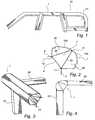
- Fig 1 is a schematic longitudinal section view of anembodiment of a body section comprising the profileaccording to the present invention.
- Fig 2 is a cross section of a profile of anembodiment of the present invention.
- Fig 3 is a perspective view of a part of the profilewith other sections attached.
- Fig 4 is a side view of fig 3.
- The embodiment of the invention, which will bedescribed in the following, is related to metal profilesfor a vehicle.
- A preferred embodiment of the invention will bedescribed with reference to the accompanying drawingswhere most of the benefits of the characteristic featuresare described.
- Referring now to fig 1, a
body section 20 in avehicle comprising ametal profile 1 according to apreferred embodiment of the invention is shown. - Fig 2 shows a section of a preferred embodiment ofsaid
metal profile 1, havingside walls baseplate 8 and twosupport walls 2a, 2b. Saidwalls base plate 8 constitute a sectional areawith at least threehollow sections baseplate 8 and saidsupport walls internal section 7 of saidmetal profile 1, with asubstantially triangularsectional area 7. - By the triangular shaped internal section thebending stiffness of the profile is doubled compared to acorresponding profile without this specific section.
- The
metal profile 1 of the present invention has atleast oneflange 3; 4. Preferably themetal profile 1 hastwoflanges metal profile 1.Theflanges internal section 7. In apreferred embodiment of the present metal profileinvention theflanges corners base plate 8 in saidinternalsection 7. - It is not an object of this invention to present aspecific method of making the metal profile, since theinvention is perfect for conventional state of the arttechniques considering the manufacturing of the profile.
- The
metal profile 1 according to a preferred methodis formed from just one piece of a metal sheet. Themethod to be used to form the profile is familiar to aperson skilled in the art and is not an object for thisparticular invention. However, the specific shape asillustrated by fig 2 makes it possible to provide such astrong but yet slender profile out of only one metalsheet. It is a further advantage that the parts andcorners that need to be securely attached areconveniently reached and treated by e.g. welding evenafter the forming process. Spot welding is a non-restrictiveexample of a preferred method to provideattachment between sides, corners or flanges of the metalprofile. - The metal profile can be manufactured by roll- orhydro forming starting from one piece of a metal sheet.An alternative, which is very suitable for some metals,is to use extrusion in order to provide a metal profileaccording to the present invention.
- Referring to fig 3 a
metal profile 1 according tothe invention that is provided with stiffener means 13 is shown. Preferably at least one of saidsupport walls supportwalls supportive walls metalprofile 1 of the present invention. - Referring now to Fig 4 showing a section of apreferred embodiment of the
body section 20 according tothe invention. Asecond profile 25 is attached to saidmetal profile 1 in a first attachment supported by aflange 4 of saidmetal profile 1. Thesecond profile 25has one further attachment to saidmetal profile 1 on adistance from the first attachment in transversaldirection relative saidmetal profile 1 and saidsecondprofile 25. - It is also an object of the present invention toprovide a
body section 20 with e.g. awindshield 21, aroof bow, a sealing flange of a rubber like material or apillar attached to saidmetal profile 1 supported by aflange 3; 4. - The present invention should not be considered asbeing limited to the above-described preferredembodiment, but rather includes all possible variationscovered by the scope defined by the appended claims.
Claims (19)
- Metal profile (1) for a vehicle body section,said profile comprising side walls (10a, 10b), a baseplate (8) and two support walls (2a, 2b), said walls (2a,2b, 10a, 10b) and base plate (8) constituting a sectionalarea with at least three hollow sections (6a, 6b, 7),characterised in that said metal profile (1) isformed from one piece of a metal sheet, said base plate(8) and said support walls (2a, 2b) constituting aninternal section (7), of said metal profile (1) with asubstantially triangular sectional area, said internaltriangular section (7) having substantially three corners(9, 11, 12) with an adjacent opening of said metalprofile material from an interior section to the outside.
- Metal profile (1) according to claim 1, whereinsaid metal profile (1) has at least one flange (3; 4).
- Metal profile (1) according to claim 1, whereinsaid metal profile (1) has two flanges (3, 4) integratedwith said metal profile (1).
- Metal profile (1) according to any of claims 2-3,wherein said flanges (3, 4) are placed closely to atleast one corner (9; 11; 12) of said internal section(7).
- Metal profile (1) according to any of claims 2-4,wherein said flanges (3, 4) are placed closely to saidcorners (11, 12) of said base plate (8) in said internalsection (7).
- Metal profile (1) according to any of claims 1-5,wherein said metal profile (1) is hydro formed fromone piece of a metal sheet.
- Metal profile (1) according to any of thepreceding claims, wherein said metal profile (1) isprovided with stiffener means (13).
- Metal profile (1) according to any of thepreceding claims, wherein at least one of said support walls (2a, 2b) of said internal section have stiffenermeans (13).
- Body section (20) in a vehicle comprising ametal profile (1) having side walls (10a, 10b), a baseplate (8) and two support walls (2a, 2b), said walls (2a,2b, 10a, 10b) and base plate (8) constituting a sectionalarea with at least three hollow sections (6a, 6b, 7),characterised in that said metal profile (1) isformed from one piece of metal sheet, said base plate (8)and said support walls (2a, 2b) constituting an internalsection (7), of said metal profile (1), with asubstantially triangular sectional area (7) said internaltriangular section (7) having substantially three corners(9, 11, 12) with an adjacent opening of said metalprofile material from an interior section to the outside.
- Body section (20) according to claim 9, whereinsaid metal profile (1) of said body section (20) has atleast one flange (3; 4).
- Body section (20) according to claim 9, whereinsaid metal profile (1) of said body section (20) has twoflanges (3, 4) integrated with the metal profile (1).
- Body section (20) according to any of claims 9-11,wherein a second profile (25) is attached to saidmetal profile (1) in a first attachment supported by aflange (3; 4) of said metal profile (1).
- Body section (20) according to any of claims-9-12,wherein said second profile (25) has at least onefurther attachment to said metal profile (1) on adistance from the first attachment in a transversedirection relative said metal profile (1) and said secondprofile (25).
- Body section (20) according to any of claims 9-13,wherein a glass panel (21) is attached to said metalprofile (1) supported by a flange (3; 4) of said metalprofile (1).
- Body section (20) according to any of claims 9-14,wherein a roof bow (26) is attached to said metal profile (1) supported by a flange (3; 4) of the metalprofile (1).
- Body section (20) according to any of claims 9-15,wherein a flange (3; 4) of said metal profileprovides a sealing flange for a vehicle door.
- Body section (20) according to any of claims 9-16,wherein a pillar (25) is attached to said metalprofile (1) supported by a flange of said metal profile(1).
- Vehicle provided with at least one metalprofile (1) according to any of claims 1-8.
- Vehicle provided with at least one body section(20) according to any of claims 9-17.
Priority Applications (3)
| Application Number | Priority Date | Filing Date | Title |
|---|---|---|---|
| DE60024829TDE60024829T2 (en) | 2000-10-16 | 2000-10-16 | Profile for a body |
| EP00122528AEP1199245B1 (en) | 2000-10-16 | 2000-10-16 | Profile for body section |
| US09/682,766US6869135B2 (en) | 2000-10-16 | 2001-10-16 | Body section |
Applications Claiming Priority (1)
| Application Number | Priority Date | Filing Date | Title |
|---|---|---|---|
| EP00122528AEP1199245B1 (en) | 2000-10-16 | 2000-10-16 | Profile for body section |
Publications (2)
| Publication Number | Publication Date |
|---|---|
| EP1199245A1 EP1199245A1 (en) | 2002-04-24 |
| EP1199245B1true EP1199245B1 (en) | 2005-12-14 |
Family
ID=8170100
Family Applications (1)
| Application Number | Title | Priority Date | Filing Date |
|---|---|---|---|
| EP00122528AExpired - LifetimeEP1199245B1 (en) | 2000-10-16 | 2000-10-16 | Profile for body section |
Country Status (3)
| Country | Link |
|---|---|
| US (1) | US6869135B2 (en) |
| EP (1) | EP1199245B1 (en) |
| DE (1) | DE60024829T2 (en) |
Families Citing this family (11)
| Publication number | Priority date | Publication date | Assignee | Title |
|---|---|---|---|---|
| US7364226B2 (en)* | 2004-08-25 | 2008-04-29 | Noble Advanced Technologies | Structural assembly having integrated outer and inner reinforced members |
| US7293823B2 (en)* | 2005-11-16 | 2007-11-13 | Ford Global Technologies, Llc | Interlocked pillar and roof rail joint |
| WO2009064304A1 (en)* | 2007-11-15 | 2009-05-22 | Ford Motor Company | Double hydroformed tube with integral reinforcement |
| IT1394074B1 (en)* | 2008-06-11 | 2012-05-25 | Ksm Castings Gmbh | NODAL ELEMENT |
| US8998307B1 (en) | 2013-10-24 | 2015-04-07 | Ford Global Technologies, Llc | Header beam of a vehicle frame and method of forming the same |
| US9027989B1 (en) | 2013-10-24 | 2015-05-12 | Ford Global Technologies, Llc | Extruded body component with notched flange to reduce strain in bending |
| US9199293B2 (en) | 2013-10-24 | 2015-12-01 | Ford Global Technologies, Llc | Header beam of a vehicle frame and method of forming the same |
| US9174680B2 (en) | 2013-10-24 | 2015-11-03 | Ford Global Technologies, Llc | Formation in hollow extruded vehicle frame component for subassembly attachment and method of forming the same |
| CN105946975B (en)* | 2016-06-12 | 2018-08-17 | 北京长城华冠汽车科技股份有限公司 | A kind of longeron reinforces crumple mechanism and includes the automobile that the longeron reinforces crumple mechanism |
| US10730557B2 (en)* | 2017-12-11 | 2020-08-04 | Ford Global Technologies, Llc | Cross car beam assembly with composite beam structure and reinforcement |
| US12122459B2 (en)* | 2020-12-21 | 2024-10-22 | Rivan IP Holdings, LLC | Aluminum-reinforced vehicle frame |
Family Cites Families (24)
| Publication number | Priority date | Publication date | Assignee | Title |
|---|---|---|---|---|
| US1461907A (en)* | 1919-12-26 | 1923-07-17 | Hughes Arthur Sheridan | Sheet-metal construction for truck bodies, etc. |
| US3132891A (en)* | 1962-02-05 | 1964-05-12 | Gen Motors Corp | Vehicle underbody construction |
| IT1165208B (en)* | 1979-05-25 | 1987-04-22 | Fiat Auto Spa | SUPPORTING FRAME FOR MOTOR VEHICLES |
| US4493506A (en)* | 1982-03-29 | 1985-01-15 | American Sunroof Corporation | Vehicle rocker panel structure |
| JPS61229637A (en)* | 1985-04-03 | 1986-10-13 | Daihatsu Motor Co Ltd | Weather strip for car |
| DE4018592A1 (en) | 1990-06-09 | 1991-12-12 | Porsche Ag | BODY FOR A MOTOR VEHICLE, ESPECIALLY A PASSENGER VEHICLE |
| JPH04221276A (en)* | 1990-12-20 | 1992-08-11 | Toyota Motor Corp | Vehicle body module assembly structure |
| DE4234463A1 (en)* | 1992-10-13 | 1994-04-14 | Walter E Spaeth | Method for producing a body support frame and a body frame produced by the method |
| DE4235738A1 (en)* | 1992-10-23 | 1994-04-28 | Audi Ag | End-side termination of a vehicle side member |
| IT1257965B (en)* | 1992-12-30 | 1996-02-19 | Fiat Auto Spa | TUBULAR STRUCTURE FOR THE CONSTRUCTION OF VEHICLE FRAMES. |
| DE4300398A1 (en)* | 1993-01-09 | 1994-07-14 | Vaw Ver Aluminium Werke Ag | Mfr. of motor vehicle body |
| DE19714631A1 (en)* | 1996-04-20 | 1997-10-30 | Volkswagen Ag | Self-supporting motor vehicle body |
| ZA973413B (en)* | 1996-04-30 | 1998-10-21 | Autokinetics Inc | Modular vehicle frame |
| EP0823368A1 (en)* | 1996-08-07 | 1998-02-11 | Menci & C. S.p.A. | An integrated structure for vehicles, in particular for industrial vehicles, such as trailers, semitrailers and similar |
| US6068330A (en)* | 1998-01-22 | 2000-05-30 | Honda Giken Kogyo Kabushiki Kaisha | Framework of an automobile body |
| JP3971521B2 (en)* | 1998-10-15 | 2007-09-05 | 本田技研工業株式会社 | Pillar joint structure for automobile |
| EP1026071A1 (en)* | 1999-02-05 | 2000-08-09 | Alusuisse Technology & Management AG | Structural beam |
| JP3303853B2 (en)* | 1999-07-15 | 2002-07-22 | 日産自動車株式会社 | Body structure |
| EP1090830B1 (en)* | 1999-10-05 | 2004-09-08 | Alcan Technology & Management AG | Connection for built-up structures |
| US6475577B1 (en)* | 2000-02-07 | 2002-11-05 | Sika Corporation | Reinforcing member with intersecting support legs |
| JP3381703B2 (en)* | 2000-03-15 | 2003-03-04 | 日産自動車株式会社 | Car floor structure |
| US6357822B1 (en)* | 2000-07-26 | 2002-03-19 | Daniel E. Panoz | Side impact beam assembly |
| JP3610927B2 (en)* | 2001-06-19 | 2005-01-19 | 日産自動車株式会社 | Car body superstructure |
| JP2003291858A (en)* | 2002-04-02 | 2003-10-15 | Honda Motor Co Ltd | Vehicle side sill reinforcement structure |
- 2000
- 2000-10-16EPEP00122528Apatent/EP1199245B1/ennot_activeExpired - Lifetime
- 2000-10-16DEDE60024829Tpatent/DE60024829T2/ennot_activeExpired - Lifetime
- 2001
- 2001-10-16USUS09/682,766patent/US6869135B2/ennot_activeExpired - Fee Related
Also Published As
| Publication number | Publication date |
|---|---|
| US20030071489A1 (en) | 2003-04-17 |
| EP1199245A1 (en) | 2002-04-24 |
| DE60024829D1 (en) | 2006-01-19 |
| US6869135B2 (en) | 2005-03-22 |
| DE60024829T2 (en) | 2006-07-06 |
Similar Documents
| Publication | Publication Date | Title |
|---|---|---|
| US6409257B1 (en) | Vehicle side sill structure | |
| US20060290166A1 (en) | Door structure for a motor vehicle | |
| US20010028179A1 (en) | Body structure | |
| KR101097018B1 (en) | Automotive doors with enhanced side impact performance | |
| EP1024073B1 (en) | Body structure of motor vehicle | |
| US6644725B2 (en) | Body pillar for a motor vehicle | |
| US7585017B2 (en) | One-piece, tubular member with an integrated welded flange and associated method for producing | |
| US7237833B1 (en) | Vehicle body structure | |
| US7144072B2 (en) | Beam and method of making same | |
| US8360490B2 (en) | Bumper crossbeam as component of a bumper of a motor vehicle | |
| US7731272B2 (en) | A-pillar force transfer structure | |
| EP1199245B1 (en) | Profile for body section | |
| US20120256445A1 (en) | Vehicle roof support pillar | |
| CN101565057A (en) | Motor vehicle frame | |
| US5466035A (en) | Improved vehicle front-end support structure for a passenger car | |
| US4750779A (en) | Vehicle with a cabin encasement with internal reinforcing elements | |
| JP2001199292A (en) | Bumper reinforcement | |
| US20070085382A1 (en) | Post in a carrier structure of a motor vehicle in a spaceframe style | |
| US7703207B2 (en) | Blank, chassis component and method for production of said chassis component | |
| JPH04238725A (en) | Impact beam for automobile doors | |
| US12391315B2 (en) | Center pillar for vehicle with improved stiffness | |
| KR100283318B1 (en) | Car body structure | |
| KR0118283Y1 (en) | Structure of car rear frame | |
| KR100342608B1 (en) | frame which has a reinforcement member in a car | |
| KR0145627B1 (en) | Car door |
Legal Events
| Date | Code | Title | Description |
|---|---|---|---|
| PUAI | Public reference made under article 153(3) epc to a published international application that has entered the european phase | Free format text:ORIGINAL CODE: 0009012 | |
| AK | Designated contracting states | Kind code of ref document:A1 Designated state(s):AT BE CH CY DE DK ES FI FR GB GR IE IT LI LU MC NL PT SE Kind code of ref document:A1 Designated state(s):AT BE CH LI | |
| AX | Request for extension of the european patent | Free format text:AL;LT;LV;MK;RO;SI | |
| 17P | Request for examination filed | Effective date:20020425 | |
| AKX | Designation fees paid | Free format text:AT BE CH LI | |
| RBV | Designated contracting states (corrected) | Designated state(s):DE GB SE | |
| REG | Reference to a national code | Ref country code:DE Ref legal event code:8566 | |
| 17Q | First examination report despatched | Effective date:20040323 | |
| GRAP | Despatch of communication of intention to grant a patent | Free format text:ORIGINAL CODE: EPIDOSNIGR1 | |
| GRAS | Grant fee paid | Free format text:ORIGINAL CODE: EPIDOSNIGR3 | |
| GRAA | (expected) grant | Free format text:ORIGINAL CODE: 0009210 | |
| RIN1 | Information on inventor provided before grant (corrected) | Inventor name:FORSSELL, JONAS | |
| AK | Designated contracting states | Kind code of ref document:B1 Designated state(s):DE GB SE | |
| RAP1 | Party data changed (applicant data changed or rights of an application transferred) | Owner name:FORD GLOBAL TECHNOLOGIES, LLC | |
| REG | Reference to a national code | Ref country code:GB Ref legal event code:FG4D | |
| REF | Corresponds to: | Ref document number:60024829 Country of ref document:DE Date of ref document:20060119 Kind code of ref document:P | |
| REG | Reference to a national code | Ref country code:SE Ref legal event code:TRGR | |
| RAP2 | Party data changed (patent owner data changed or rights of a patent transferred) | Owner name:FORD GLOBAL TECHNOLOGIES, LLC. | |
| PLBE | No opposition filed within time limit | Free format text:ORIGINAL CODE: 0009261 | |
| STAA | Information on the status of an ep patent application or granted ep patent | Free format text:STATUS: NO OPPOSITION FILED WITHIN TIME LIMIT | |
| 26N | No opposition filed | Effective date:20060915 | |
| REG | Reference to a national code | Ref country code:GB Ref legal event code:732E Free format text:REGISTERED BETWEEN 20111020 AND 20111025 | |
| REG | Reference to a national code | Ref country code:DE Ref legal event code:R082 Ref document number:60024829 Country of ref document:DE Representative=s name:LICHTI PATENTANWAELTE, DE | |
| REG | Reference to a national code | Ref country code:DE Ref legal event code:R082 Ref document number:60024829 Country of ref document:DE Representative=s name:LICHTI PATENTANWAELTE, DE Effective date:20120207 Ref country code:DE Ref legal event code:R081 Ref document number:60024829 Country of ref document:DE Owner name:VOLVO CAR CORPORATION, SE Free format text:FORMER OWNER: FORD GLOBAL TECHNOLOGIES, LLC, DEARBORN, MICH., US Effective date:20120207 Ref country code:DE Ref legal event code:R082 Ref document number:60024829 Country of ref document:DE Representative=s name:LICHTI - PATENTANWAELTE PARTNERSCHAFT MBB, DE Effective date:20120207 | |
| PGFP | Annual fee paid to national office [announced via postgrant information from national office to epo] | Ref country code:DE Payment date:20141015 Year of fee payment:15 Ref country code:GB Payment date:20141015 Year of fee payment:15 Ref country code:SE Payment date:20141027 Year of fee payment:15 | |
| REG | Reference to a national code | Ref country code:DE Ref legal event code:R119 Ref document number:60024829 Country of ref document:DE | |
| REG | Reference to a national code | Ref country code:SE Ref legal event code:EUG | |
| GBPC | Gb: european patent ceased through non-payment of renewal fee | Effective date:20151016 | |
| PG25 | Lapsed in a contracting state [announced via postgrant information from national office to epo] | Ref country code:GB Free format text:LAPSE BECAUSE OF NON-PAYMENT OF DUE FEES Effective date:20151016 Ref country code:DE Free format text:LAPSE BECAUSE OF NON-PAYMENT OF DUE FEES Effective date:20160503 | |
| PG25 | Lapsed in a contracting state [announced via postgrant information from national office to epo] | Ref country code:SE Free format text:LAPSE BECAUSE OF NON-PAYMENT OF DUE FEES Effective date:20151017 |