EP1199219A1 - Rear view mirror for vehicles - Google Patents
Rear view mirror for vehiclesDownload PDFInfo
- Publication number
- EP1199219A1 EP1199219A1EP01117354AEP01117354AEP1199219A1EP 1199219 A1EP1199219 A1EP 1199219A1EP 01117354 AEP01117354 AEP 01117354AEP 01117354 AEP01117354 AEP 01117354AEP 1199219 A1EP1199219 A1EP 1199219A1
- Authority
- EP
- European Patent Office
- Prior art keywords
- mirror
- motor vehicle
- vehicle rear
- mirror glass
- rear view
- Prior art date
- Legal status (The legal status is an assumption and is not a legal conclusion. Google has not performed a legal analysis and makes no representation as to the accuracy of the status listed.)
- Withdrawn
Links
Images


Classifications
- B—PERFORMING OPERATIONS; TRANSPORTING
- B60—VEHICLES IN GENERAL
- B60R—VEHICLES, VEHICLE FITTINGS, OR VEHICLE PARTS, NOT OTHERWISE PROVIDED FOR
- B60R1/00—Optical viewing arrangements; Real-time viewing arrangements for drivers or passengers using optical image capturing systems, e.g. cameras or video systems specially adapted for use in or on vehicles
- B60R1/02—Rear-view mirror arrangements
- B60R1/06—Rear-view mirror arrangements mounted on vehicle exterior
- B60R1/062—Rear-view mirror arrangements mounted on vehicle exterior with remote control for adjusting position
- B60R1/07—Rear-view mirror arrangements mounted on vehicle exterior with remote control for adjusting position by electrically powered actuators
- B60R1/072—Rear-view mirror arrangements mounted on vehicle exterior with remote control for adjusting position by electrically powered actuators for adjusting the mirror relative to its housing
- B—PERFORMING OPERATIONS; TRANSPORTING
- B60—VEHICLES IN GENERAL
- B60R—VEHICLES, VEHICLE FITTINGS, OR VEHICLE PARTS, NOT OTHERWISE PROVIDED FOR
- B60R1/00—Optical viewing arrangements; Real-time viewing arrangements for drivers or passengers using optical image capturing systems, e.g. cameras or video systems specially adapted for use in or on vehicles
- B60R1/02—Rear-view mirror arrangements
- B60R1/06—Rear-view mirror arrangements mounted on vehicle exterior
Definitions
- the inventionrelates to motor vehicle rear view mirrors, with a mirror glass drive, consisting of at least one drive motor and a subordinate Reduction gear, which is articulated via adjusting elements with a mirror glass support plate is connected, which is pivotable about a central joint by two vertically mutually arranged pivot axes pivotable with the mirror glass drive connected is.
- the mirror glass carrier platein is essentially formed by stiffening ribs in the form of a honeycomb structure. hereby the mirror glass support plate is equally resilient in all spatial directions and that Very low susceptibility to vibration.
- the mirror glass carrier plateis made of a plastic material, this is a clear one Weight saving compared to a mirror glass carrier plate made of a metal material and more economical production possible. Because of the honeycomb structure Plastic material can be used without having to accept a higher sensitivity to vibrations have to.
- a floorprovides greater stability and rigidity for the mirror glass carrier plate achieved that is parallel to a mirror surface on one side of the stiffening ribs or is arranged between both sides of the mirror glass support plate.
- a particularly low susceptibility to vibrationscan be achieved through a large number of floors, one of which is arranged in each honeycomb and the multitude of floors different levels are arranged parallel to a mirror surface.
- the size of the honeycombprefferably be smaller in areas with high stress than in To train areas with less stress because this creates an optimal ratio of weight and strength is possible.
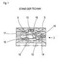
- FIG. 1shows a mirror glass carrier plate 3 of a known motor vehicle rear view mirror, with a central joint 9, a first and second connection point 14, 15 for the articulated connection with adjusting elements, recesses 16 for carrying out Assembly tools, stiffening ribs 5, a bottom 10 and an edge 17th
- FIG. 2shows a first embodiment of a mirror glass carrier plate 3 of a Motor vehicle rear view mirror according to the invention, with stiffening ribs 5 in the form of a Honeycomb structure with a plurality of honeycombs 12, an edge 17, a central joint 9, a first and second connection point 14, 15 for the articulated connection with Adjusting elements, the first pivot axis 6 and the second pivot axis 7.
- Fig. 3shows a sectional view of the first embodiment in a simplified representation, with the mirror glass support plate 3, the central joint 9, the edge 17, the Stiffening ribs 5, the honeycomb 12 and a bottom 10.
- honeycombs 12On both sides of the bottom 10 honeycombs 12 are arranged, the height h1, h2 of the honeycombs 12 being different.
- the honeycombs 12are offset from one another on both sides of the base 10.
- Fig. 4shows a variant of the first embodiment, with the mirror glass support plate 3, the central joint 9, the edge 17, the stiffening ribs 5, the honeycomb 12 and one Plurality of floors 10 that are parallel to a mirror surface 13 at different levels (only indicated) are arranged.
- Fig. 5shows a second embodiment, with the mirror glass support plate 3, the central Joint 9, the stiffening ribs 5, the honeycomb 12, the edge 17 and passages 11. Die Passages 11 are as large as the honeycomb 12 here, but variants are also conceivable, in which the passages 11 are smaller than the honeycomb 12.
- FIG. 6shows a variant of the second embodiment, with the mirror glass carrier plate 3, the central joint 9, the stiffening ribs 5, the honeycomb 12, the passages 11 and the edge 17.
- the mirror glass carrier plate 3is thinner here in an edge region 8 trained as in the central area.
Landscapes
- Engineering & Computer Science (AREA)
- Multimedia (AREA)
- Mechanical Engineering (AREA)
- Rear-View Mirror Devices That Are Mounted On The Exterior Of The Vehicle (AREA)
Abstract
Description
Translated fromGermanDie Erfindung betrifft Kraftfahrzeug-Rückblickspiegel, mit einem Spiegelglasantrieb,bestehend aus zumindest einem Antriebsmotor und einem nachgeordnetenUntersetzungsgetriebe, das über Verstellelemente mit einer Spiegelglasträgerplatte gelenkigverbunden ist, die schwenkbeweglich über ein zentrales Gelenk um zwei senkrechtzueinander angeordnete Schwenkachsen verschwenkbar mit dem Spiegelglasantriebverbunden ist.The invention relates to motor vehicle rear view mirrors, with a mirror glass drive,consisting of at least one drive motor and a subordinateReduction gear, which is articulated via adjusting elements with a mirror glass support plateis connected, which is pivotable about a central joint by two verticallymutually arranged pivot axes pivotable with the mirror glass driveconnected is.
Aus der DE-PS 196 44 824 C1 ist ein Kraftfahrzeug-Rückblickspiegel mit einer vollflächigenSpiegelglasträgerplatte bekannt, bei der zur Versteifung unterschiedlich geformte undunterschiedlich angeordnete Versteifungsrippen vorgesehen sind. Durch diese Anordnungder Versteifungsrippen werden Kräfte in unterschiedlichen Richtungen unterschiedlichweitergeleitet und Vibrationen richtungsabhängig mehr oder weniger stark gedämpft. BeiÄnderung der äußeren Bedingungen kann daher eine aufwändige Anpassung dergeometrischen Anordnung der Versteifungsrippen erforderlich werden.From DE-PS 196 44 824 C1 is a motor vehicle rear view mirror with a full surfaceMirror glass backing plate is known, in which differently shaped and stiffeningdifferently arranged stiffening ribs are provided. By this arrangementthe stiffening ribs, forces are different in different directionsforwarded and vibrations more or less damped depending on the direction. atChanging the external conditions can therefore be a complex adjustment of thegeometric arrangement of the stiffening ribs are required.
Daher ist es Aufgabe der vorliegenden Erfindung einen Kraftfahrzeug-Rückblickspiegel miteiner Spiegelglasträgerplatte zu versehen, die eine möglichst homogene Struktur aufweist,richtungsunabhängig belastbar ist und eine möglichst geringe Vibrationsanfälligkeit besitzt.It is therefore an object of the present invention to have a motor vehicle rear view mirrorto provide a mirror glass carrier plate which has a structure which is as homogeneous as possible,is loadable regardless of direction and has the lowest possible susceptibility to vibration.
Diese Aufgabe wird erfindungsgemäß dadurch gelöst, dass die Spiegelglasträgerplatte imwesentlichen durch Versteifungsrippen in Form einer Wabenstruktur gebildet wird. Hierdurchist die Spiegelglasträgerplatte in allen Raumrichtungen gleichmäßig belastbar und dieVibrationsanfälligkeit sehr gering.This object is achieved in that the mirror glass carrier plate inis essentially formed by stiffening ribs in the form of a honeycomb structure. herebythe mirror glass support plate is equally resilient in all spatial directions and thatVery low susceptibility to vibration.
Bei Ausbildung der Spiegelglasträgerplatte aus einem Kunststoffmaterial ist eine deutlicheGewichtseinsparung gegenüber einer Spiegelglasträgerplatte aus einem Metallmaterial undeine wirtschaftlichere Herstellung möglich. Durch die Wabenstruktur ist dasKunststoffmaterial verwendbar, ohne eine höhere Vibrationsanfälligkeit in Kauf nehmen zumüssen.If the mirror glass carrier plate is made of a plastic material, this is a clear oneWeight saving compared to a mirror glass carrier plate made of a metal material andmore economical production possible. Because of the honeycomb structurePlastic material can be used without having to accept a higher sensitivity to vibrationshave to.
Eine größere Stabilität und Steifigkeit der Spiegelglasträgerplatte wird durch einen Bodenerreicht, der parallel zu einer Spiegelfläche auf einer Seite der Versteifungsrippen oderzwischen beiden Seiten der Spiegelglasträgerplatte angeordnet ist.A floor provides greater stability and rigidity for the mirror glass carrier plateachieved that is parallel to a mirror surface on one side of the stiffening ribs oris arranged between both sides of the mirror glass support plate.
Eine besonders geringe Vibrationsanfälligkeit ist durch eine Vielzahl von Böden erreichbar,von denen je einer in jeder Wabe angeordnet ist und die Vielzahl von Böden aufunterschiedlichen Niveaus parallel zu einer Spiegelfläche angeordnet sind.A particularly low susceptibility to vibrations can be achieved through a large number of floors,one of which is arranged in each honeycomb and the multitude of floorsdifferent levels are arranged parallel to a mirror surface.
Geringeres Gewicht und daher auch eine verringerte Vibrationsanfälligkeit bei hoherStabilität und Steifigkeit ist erreichbar indem der größere Teil der tragenden Bereiche derSpiegelglasträgerplatte ausschließlich durch die Versteifungsrippen gebildet wird, wobeizwischen diesen Versteifungsrippen Durchgänge vorgesehen sind. Noch deutlicher wirddieser Effekt bei Verwendung von Waben, die innen völlig freigespart sind.Lower weight and therefore also reduced susceptibility to vibrations with high onesStability and rigidity can be achieved by the greater part of the load-bearing areas of theMirror glass support plate is formed exclusively by the stiffening ribs, wherebypassages are provided between these stiffening ribs. It becomes even clearerthis effect when using honeycombs that are completely free inside.
Weitere Gewichtseinsparungen sind möglich durch unterschiedlich hoch ausgebildeteVersteifungsrippen, wobei an den Stellen, die eine höhere Beanspruchung erfahren höhereVersteifungsrippen vorzusehen sind. Daher ist vorgesehen dass die Versteifungsrippen voneinem Randbereich der Spiegelglasträgerplatte zum zentralen Gelenk hin kegelförmig höherwerdend ausgebildet sind.Further weight savings are possible through differently trainedStiffening ribs, being higher in the places that are subjected to greater stressStiffening ribs are to be provided. It is therefore envisaged that the stiffening ribs ofan edge area of the mirror glass support plate towards the central joint is conically higherare trained.
Es ist von Vorteil die Größe der Waben in Bereichen mit hoher Beanspruchung kleiner als inBereichen mit geringerer Beanspruchung auszubilden, weil dadurch ein optimales Verhältnisvon Gewicht und Festigkeit möglich ist.It is advantageous for the size of the honeycomb to be smaller in areas with high stress than inTo train areas with less stress because this creates an optimal ratioof weight and strength is possible.
Ausführungsbeispiele der Erfindung werden nachfolgend anhand der Zeichnung nähererläutert. Es zeigen:
- Fig. 1
- eine Spiegelglasträgerplatte eines bekannten Kraftfahrzeug-Rückblickspiegels,
- Fig. 2
- eine erste Ausführungsform einer Spiegelglasträgerplatte eines erfindungsgemäßenKraftfahrzeug-Rückblickspiegels,
- Fig. 3
- eine Schnittansicht der ersten Ausführungsform,
- Fig. 4
- eine Variante der ersten Ausführungsform im Schnitt,
- Fig. 5
- eine zweite Ausführungsform im Schnitt und
- Fig. 6
- eine Variante der zweiten Ausführungsform.
- Fig. 1
- a mirror glass carrier plate of a known motor vehicle rearview mirror,
- Fig. 2
- A first embodiment of a mirror glass carrier plate of a motor vehicle rear view mirror according to the invention,
- Fig. 3
- 2 shows a sectional view of the first embodiment,
- Fig. 4
- a variant of the first embodiment in section,
- Fig. 5
- a second embodiment in section and
- Fig. 6
- a variant of the second embodiment.
Fig. 1 zeigt eine Spiegelglasträgerplatte 3 eines bekannten Kraftfahrzeug-Rückblickspiegels,mit einem zentralen Gelenk 9, einer ersten und zweiten Verbindungsstelle 14, 15 für diegelenkige Verbindung mit Verstellelementen, Ausnehmungen 16 zur Durchführung vonMontagewerkzeugen, Versteifungsrippen 5, einem Boden 10 und einem Rand 17.1 shows a mirror
Fig. 2 zeigt eine erste Ausführungsform einer Spiegelglasträgerplatte 3 eineserfindungsgemäßen Kraftfahrzeug-Rückblickspiegels, mit Versteifungsrippen 5 in Form einerWabenstruktur mit einer Vielzahl von Waben 12, einem Rand 17, einem zentralen Gelenk 9,eine erste und zweite Verbindungsstelle 14, 15 für die gelenkige Verbindung mitVerstellelementen, der ersten Schwenkachse 6 und der zweiten Schwenkachse 7.2 shows a first embodiment of a mirror
Fig. 3 zeigt eine Schnittansicht der ersten Ausführungsform in vereinfachter Darstellung, mitder Spiegelglasträgerplatte 3, dem zentralen Gelenk 9, dem Rand 17, denVersteifungsrippen 5, den Waben 12 und einem Boden 10. Auf beiden Seiten des Bodens 10sind Waben 12 angeordnet, wobei die Höhe h1, h2 der Waben 12 unterschiedlich ist.Zueinander sind die Waben 12 beiderseits des Bodens 10 versetzt angeordnet.Fig. 3 shows a sectional view of the first embodiment in a simplified representation, withthe mirror
Fig. 4 zeigt eine Variante der ersten Ausführungsform, mit der Spiegelglasträgerplatte 3, demzentralen Gelenk 9, dem Rand 17, den Versteifungsrippen 5, den Waben 12 und einerVielzahl an Böden 10, die auf unterschiedlichen Niveaus parallel zu einer Spiegelfläche 13(nur angedeutet) angeordnet sind.Fig. 4 shows a variant of the first embodiment, with the mirror
Fig. 5 zeigt eine zweite Ausführungsform, mit der Spiegelglasträgerplatte 3, dem zentralenGelenk 9, den Versteifungsrippen 5, den Waben 12, dem Rand 17 und Duchgängen 11. DieDurchgänge 11 sind hier so groß wie die Waben 12, es sind aber auch Varianten denkbar,bei denen die Durchgänge 11 kleiner als die Waben 12 sind.Fig. 5 shows a second embodiment, with the mirror
Fig. 6 zeigt eine Variante der zweiten Ausführungsform, mit der Spiegelglasträgerplatte 3,dem zentralen Gelenk 9, den Versteifungsrippen 5, den Waben 12, den Durchgängen 11 unddem Rand 17. Die Spiegelglasträgerplatte 3 ist hier in einem Randbereich 8 dünnerausgebildet als im zentralen Bereich.6 shows a variant of the second embodiment, with the mirror
- 11
- Kraftfahrzeug-RückblickspiegelAutomotive rearview mirror
- 22
- SpiegelglasantriebMirror glass drive
- 33
- SpiegelglasträgerplatteMirror glass carrier plate
- 44
- Verstellelementeadjusting
- 55
- Versteifungsrippenstiffening ribs
- 66
- erste Schwenkachsefirst pivot axis
- 77
- zweite Schwenkachsesecond pivot axis
- 88th
- Randbereich der SpiegelglasträgerplatteEdge area of the mirror glass carrier plate
- 99
- zentrales Gelenkcentral joint
- 1010
- Bodenground
- 1111
- Durchgängecrossings
- 1212
- Wabehoneycomb
- 1313
- Spiegelflächemirror surface
- 1414
- erste Verbindungsstellefirst connection point
- 1515
- zweite Verbindungsstellesecond connection point
- 1616
- Ausnehmungenrecesses
- 1717
- Randedge
Claims (9)
Translated fromGermanApplications Claiming Priority (2)
| Application Number | Priority Date | Filing Date | Title |
|---|---|---|---|
| DE10051240 | 2000-10-17 | ||
| DE10051240ADE10051240A1 (en) | 2000-10-17 | 2000-10-17 | Automotive rearview mirror |
Publications (1)
| Publication Number | Publication Date |
|---|---|
| EP1199219A1true EP1199219A1 (en) | 2002-04-24 |
Family
ID=7659965
Family Applications (1)
| Application Number | Title | Priority Date | Filing Date |
|---|---|---|---|
| EP01117354AWithdrawnEP1199219A1 (en) | 2000-10-17 | 2001-07-18 | Rear view mirror for vehicles |
Country Status (2)
| Country | Link |
|---|---|
| EP (1) | EP1199219A1 (en) |
| DE (1) | DE10051240A1 (en) |
Cited By (2)
| Publication number | Priority date | Publication date | Assignee | Title |
|---|---|---|---|---|
| EP1481828A1 (en)* | 2003-05-27 | 2004-12-01 | Behr France S.A.R.L. | Wall structure, in particular for a motor vehicle |
| DE102004028389A1 (en)* | 2004-06-14 | 2005-12-29 | Behr Gmbh & Co. Kg | Structure for sides of a motor vehicle which is honeycomb-shaped and fitted with a filling material, and use of structure in vehicle ventilation housing or water tanks |
Citations (4)
| Publication number | Priority date | Publication date | Assignee | Title |
|---|---|---|---|---|
| US4701037A (en)* | 1986-02-13 | 1987-10-20 | Lacks Industries, Inc. | Remote control rear view mirror, electrically operated |
| EP0449056A2 (en)* | 1990-03-29 | 1991-10-02 | MEKRA Lang GmbH & Co. KG | Exterior mirror for lorries |
| EP0590510A1 (en)* | 1992-10-02 | 1994-04-06 | MEKRA Lang GmbH & Co. KG | External rear-view mirror for trucks |
| EP0983900A2 (en)* | 1998-09-02 | 2000-03-08 | MEKRA Lang GmbH & Co. KG | Exterior vehicle mirror |
- 2000
- 2000-10-17DEDE10051240Apatent/DE10051240A1/ennot_activeWithdrawn
- 2001
- 2001-07-18EPEP01117354Apatent/EP1199219A1/ennot_activeWithdrawn
Patent Citations (4)
| Publication number | Priority date | Publication date | Assignee | Title |
|---|---|---|---|---|
| US4701037A (en)* | 1986-02-13 | 1987-10-20 | Lacks Industries, Inc. | Remote control rear view mirror, electrically operated |
| EP0449056A2 (en)* | 1990-03-29 | 1991-10-02 | MEKRA Lang GmbH & Co. KG | Exterior mirror for lorries |
| EP0590510A1 (en)* | 1992-10-02 | 1994-04-06 | MEKRA Lang GmbH & Co. KG | External rear-view mirror for trucks |
| EP0983900A2 (en)* | 1998-09-02 | 2000-03-08 | MEKRA Lang GmbH & Co. KG | Exterior vehicle mirror |
Cited By (2)
| Publication number | Priority date | Publication date | Assignee | Title |
|---|---|---|---|---|
| EP1481828A1 (en)* | 2003-05-27 | 2004-12-01 | Behr France S.A.R.L. | Wall structure, in particular for a motor vehicle |
| DE102004028389A1 (en)* | 2004-06-14 | 2005-12-29 | Behr Gmbh & Co. Kg | Structure for sides of a motor vehicle which is honeycomb-shaped and fitted with a filling material, and use of structure in vehicle ventilation housing or water tanks |
Also Published As
| Publication number | Publication date |
|---|---|
| DE10051240A1 (en) | 2002-07-11 |
Similar Documents
| Publication | Publication Date | Title |
|---|---|---|
| DE102007049864B4 (en) | Seat frame of a motor vehicle seat with a seat support, which has two side parts | |
| EP1057665B1 (en) | Axle suspension for rigid axles in vehicles | |
| DE69825711T2 (en) | Cab for a construction machine | |
| DE10145206B4 (en) | Backrest for a motor vehicle seat | |
| DE60118903T2 (en) | BLADE SPRING ELEMENT WITH ALL SHEET LEAF SPRING ELEMENT AND HALF LEAF SHEET SPRING ELEMENT | |
| EP2252475B1 (en) | Device for elastically mounting an engine transmission unit | |
| DE3622188A1 (en) | CONNECTION CONSTRUCTION BETWEEN FRONT COLUMNS AND A FRONT PANEL IN A VEHICLE | |
| DE3223814A1 (en) | DEVICE FOR ADJUSTING THE HEIGHT OF THE FRONT PANEL OF A SEAT PAD | |
| EP1243461B1 (en) | Seat base body for a vehicle seat | |
| DE4402864C2 (en) | Backrest cushion for rear seats of motor vehicles | |
| EP0853561B1 (en) | Wiper blade for the windscreen wiper device of a vehicle, in particular a motor vehicle | |
| EP1390229A2 (en) | Height-adjustable cantilever seat fixing | |
| DE102005060446A1 (en) | Vehicle seat, in particular motor vehicle seat | |
| DE4303006C2 (en) | Backrest for vehicle seats, in particular motor vehicle seats | |
| WO2011029697A1 (en) | Cantilevered seat support | |
| DE3543085C2 (en) | ||
| DE60025894T2 (en) | Rear floor pan for motor vehicles | |
| DE10260062A1 (en) | Leaf spring for a motor vehicle suspension | |
| DE3624537C2 (en) | ||
| DE19644170A1 (en) | Sheathing for vertically adjustable steering column in vehicle | |
| DE202008005536U1 (en) | Motor and guide arrangement for same | |
| DE102020116936B4 (en) | Vehicle body connection structure | |
| DE19655146C2 (en) | Longitudinally and inclinable motor vehicle seat | |
| EP1199219A1 (en) | Rear view mirror for vehicles | |
| DE19853540A1 (en) | Connection between leaf spring ends and axle bearings of a double axle unit of a truck |
Legal Events
| Date | Code | Title | Description |
|---|---|---|---|
| PUAI | Public reference made under article 153(3) epc to a published international application that has entered the european phase | Free format text:ORIGINAL CODE: 0009012 | |
| AK | Designated contracting states | Kind code of ref document:A1 Designated state(s):AT BE CH CY DE DK ES FI FR GB GR IE IT LI LU MC NL PT SE TR | |
| AX | Request for extension of the european patent | Free format text:AL;LT;LV;MK;RO;SI | |
| AKX | Designation fees paid | Free format text:AT BE CH CY DE DK ES FI FR GB GR IE IT LI LU MC NL PT SE TR | |
| STAA | Information on the status of an ep patent application or granted ep patent | Free format text:STATUS: THE APPLICATION IS DEEMED TO BE WITHDRAWN | |
| 18D | Application deemed to be withdrawn | Effective date:20021025 |