EP1197409A2 - Vehicle dynamics control method - Google Patents
Vehicle dynamics control methodDownload PDFInfo
- Publication number
- EP1197409A2 EP1197409A2EP01122836AEP01122836AEP1197409A2EP 1197409 A2EP1197409 A2EP 1197409A2EP 01122836 AEP01122836 AEP 01122836AEP 01122836 AEP01122836 AEP 01122836AEP 1197409 A2EP1197409 A2EP 1197409A2
- Authority
- EP
- European Patent Office
- Prior art keywords
- vehicle
- control system
- driving
- adhesion
- wheel
- Prior art date
- Legal status (The legal status is an assumption and is not a legal conclusion. Google has not performed a legal analysis and makes no representation as to the accuracy of the status listed.)
- Granted
Links
- 238000000034methodMethods0.000titleabstractdescription8
- 238000004364calculation methodMethods0.000claimsdescription13
- 238000005094computer simulationMethods0.000claimsdescription2
- 239000013641positive controlSubstances0.000claims2
- 230000001133accelerationEffects0.000description15
- 239000003381stabilizerSubstances0.000description8
- 230000000694effectsEffects0.000description7
- 239000000725suspensionSubstances0.000description7
- 230000008859changeEffects0.000description3
- 238000013016dampingMethods0.000description3
- 230000004069differentiationEffects0.000description3
- 230000009471actionEffects0.000description2
- 230000006641stabilisationEffects0.000description2
- 238000011105stabilizationMethods0.000description2
- 230000000087stabilizing effectEffects0.000description2
- 239000006096absorbing agentSubstances0.000description1
- 239000008186active pharmaceutical agentSubstances0.000description1
- 230000008901benefitEffects0.000description1
- 238000004590computer programMethods0.000description1
- 230000003247decreasing effectEffects0.000description1
- 230000001419dependent effectEffects0.000description1
- 238000010586diagramMethods0.000description1
- 238000005516engineering processMethods0.000description1
- 230000003631expected effectEffects0.000description1
- 230000002349favourable effectEffects0.000description1
- 230000005484gravityEffects0.000description1
- 230000006872improvementEffects0.000description1
- 238000005457optimizationMethods0.000description1
- 238000012913prioritisationMethods0.000description1
- 230000008569processEffects0.000description1
- 230000035939shockEffects0.000description1
- 238000004088simulationMethods0.000description1
- 230000002123temporal effectEffects0.000description1
- 230000007704transitionEffects0.000description1
Images


Classifications
- B—PERFORMING OPERATIONS; TRANSPORTING
- B60—VEHICLES IN GENERAL
- B60W—CONJOINT CONTROL OF VEHICLE SUB-UNITS OF DIFFERENT TYPE OR DIFFERENT FUNCTION; CONTROL SYSTEMS SPECIALLY ADAPTED FOR HYBRID VEHICLES; ROAD VEHICLE DRIVE CONTROL SYSTEMS FOR PURPOSES NOT RELATED TO THE CONTROL OF A PARTICULAR SUB-UNIT
- B60W30/00—Purposes of road vehicle drive control systems not related to the control of a particular sub-unit, e.g. of systems using conjoint control of vehicle sub-units
- B60W30/02—Control of vehicle driving stability
- B—PERFORMING OPERATIONS; TRANSPORTING
- B60—VEHICLES IN GENERAL
- B60G—VEHICLE SUSPENSION ARRANGEMENTS
- B60G17/00—Resilient suspensions having means for adjusting the spring or vibration-damper characteristics, for regulating the distance between a supporting surface and a sprung part of vehicle or for locking suspension during use to meet varying vehicular or surface conditions, e.g. due to speed or load
- B60G17/015—Resilient suspensions having means for adjusting the spring or vibration-damper characteristics, for regulating the distance between a supporting surface and a sprung part of vehicle or for locking suspension during use to meet varying vehicular or surface conditions, e.g. due to speed or load the regulating means comprising electric or electronic elements
- B60G17/0195—Resilient suspensions having means for adjusting the spring or vibration-damper characteristics, for regulating the distance between a supporting surface and a sprung part of vehicle or for locking suspension during use to meet varying vehicular or surface conditions, e.g. due to speed or load the regulating means comprising electric or electronic elements characterised by the regulation being combined with other vehicle control systems
- B—PERFORMING OPERATIONS; TRANSPORTING
- B60—VEHICLES IN GENERAL
- B60T—VEHICLE BRAKE CONTROL SYSTEMS OR PARTS THEREOF; BRAKE CONTROL SYSTEMS OR PARTS THEREOF, IN GENERAL; ARRANGEMENT OF BRAKING ELEMENTS ON VEHICLES IN GENERAL; PORTABLE DEVICES FOR PREVENTING UNWANTED MOVEMENT OF VEHICLES; VEHICLE MODIFICATIONS TO FACILITATE COOLING OF BRAKES
- B60T8/00—Arrangements for adjusting wheel-braking force to meet varying vehicular or ground-surface conditions, e.g. limiting or varying distribution of braking force
- B60T8/17—Using electrical or electronic regulation means to control braking
- B60T8/1755—Brake regulation specially adapted to control the stability of the vehicle, e.g. taking into account yaw rate or transverse acceleration in a curve
- B—PERFORMING OPERATIONS; TRANSPORTING
- B62—LAND VEHICLES FOR TRAVELLING OTHERWISE THAN ON RAILS
- B62D—MOTOR VEHICLES; TRAILERS
- B62D6/00—Arrangements for automatically controlling steering depending on driving conditions sensed and responded to, e.g. control circuits
- B—PERFORMING OPERATIONS; TRANSPORTING
- B62—LAND VEHICLES FOR TRAVELLING OTHERWISE THAN ON RAILS
- B62D—MOTOR VEHICLES; TRAILERS
- B62D7/00—Steering linkage; Stub axles or their mountings
- B62D7/06—Steering linkage; Stub axles or their mountings for individually-pivoted wheels, e.g. on king-pins
- B62D7/14—Steering linkage; Stub axles or their mountings for individually-pivoted wheels, e.g. on king-pins the pivotal axes being situated in more than one plane transverse to the longitudinal centre line of the vehicle, e.g. all-wheel steering
- B62D7/15—Steering linkage; Stub axles or their mountings for individually-pivoted wheels, e.g. on king-pins the pivotal axes being situated in more than one plane transverse to the longitudinal centre line of the vehicle, e.g. all-wheel steering characterised by means varying the ratio between the steering angles of the steered wheels
- B62D7/159—Steering linkage; Stub axles or their mountings for individually-pivoted wheels, e.g. on king-pins the pivotal axes being situated in more than one plane transverse to the longitudinal centre line of the vehicle, e.g. all-wheel steering characterised by means varying the ratio between the steering angles of the steered wheels characterised by computing methods or stabilisation processes or systems, e.g. responding to yaw rate, lateral wind, load, road condition
- B—PERFORMING OPERATIONS; TRANSPORTING
- B60—VEHICLES IN GENERAL
- B60G—VEHICLE SUSPENSION ARRANGEMENTS
- B60G2400/00—Indexing codes relating to detected, measured or calculated conditions or factors
- B60G2400/60—Load
- B60G2400/61—Load distribution
- B—PERFORMING OPERATIONS; TRANSPORTING
- B60—VEHICLES IN GENERAL
- B60G—VEHICLE SUSPENSION ARRANGEMENTS
- B60G2500/00—Indexing codes relating to the regulated action or device
- B60G2500/10—Damping action or damper
- B—PERFORMING OPERATIONS; TRANSPORTING
- B60—VEHICLES IN GENERAL
- B60G—VEHICLE SUSPENSION ARRANGEMENTS
- B60G2500/00—Indexing codes relating to the regulated action or device
- B60G2500/20—Spring action or springs
- B—PERFORMING OPERATIONS; TRANSPORTING
- B60—VEHICLES IN GENERAL
- B60G—VEHICLE SUSPENSION ARRANGEMENTS
- B60G2800/00—Indexing codes relating to the type of movement or to the condition of the vehicle and to the end result to be achieved by the control action
- B60G2800/90—System Controller type
- B60G2800/91—Suspension Control
- B—PERFORMING OPERATIONS; TRANSPORTING
- B60—VEHICLES IN GENERAL
- B60G—VEHICLE SUSPENSION ARRANGEMENTS
- B60G2800/00—Indexing codes relating to the type of movement or to the condition of the vehicle and to the end result to be achieved by the control action
- B60G2800/90—System Controller type
- B60G2800/92—ABS - Brake Control
- B60G2800/922—EBV - Electronic brake force distribution
- B—PERFORMING OPERATIONS; TRANSPORTING
- B60—VEHICLES IN GENERAL
- B60G—VEHICLE SUSPENSION ARRANGEMENTS
- B60G2800/00—Indexing codes relating to the type of movement or to the condition of the vehicle and to the end result to be achieved by the control action
- B60G2800/90—System Controller type
- B60G2800/96—ASC - Assisted or power Steering control
- B60G2800/962—Four-wheel steering
- B—PERFORMING OPERATIONS; TRANSPORTING
- B60—VEHICLES IN GENERAL
- B60G—VEHICLE SUSPENSION ARRANGEMENTS
- B60G2800/00—Indexing codes relating to the type of movement or to the condition of the vehicle and to the end result to be achieved by the control action
- B60G2800/90—System Controller type
- B60G2800/97—Engine Management System [EMS]
- B—PERFORMING OPERATIONS; TRANSPORTING
- B60—VEHICLES IN GENERAL
- B60T—VEHICLE BRAKE CONTROL SYSTEMS OR PARTS THEREOF; BRAKE CONTROL SYSTEMS OR PARTS THEREOF, IN GENERAL; ARRANGEMENT OF BRAKING ELEMENTS ON VEHICLES IN GENERAL; PORTABLE DEVICES FOR PREVENTING UNWANTED MOVEMENT OF VEHICLES; VEHICLE MODIFICATIONS TO FACILITATE COOLING OF BRAKES
- B60T2240/00—Monitoring, detecting wheel/tyre behaviour; counteracting thereof
- B60T2240/06—Wheel load; Wheel lift
- B—PERFORMING OPERATIONS; TRANSPORTING
- B60—VEHICLES IN GENERAL
- B60T—VEHICLE BRAKE CONTROL SYSTEMS OR PARTS THEREOF; BRAKE CONTROL SYSTEMS OR PARTS THEREOF, IN GENERAL; ARRANGEMENT OF BRAKING ELEMENTS ON VEHICLES IN GENERAL; PORTABLE DEVICES FOR PREVENTING UNWANTED MOVEMENT OF VEHICLES; VEHICLE MODIFICATIONS TO FACILITATE COOLING OF BRAKES
- B60T2260/00—Interaction of vehicle brake system with other systems
- B60T2260/02—Active Steering, Steer-by-Wire
- B60T2260/022—Rear-wheel steering; Four-wheel steering
- B—PERFORMING OPERATIONS; TRANSPORTING
- B60—VEHICLES IN GENERAL
- B60T—VEHICLE BRAKE CONTROL SYSTEMS OR PARTS THEREOF; BRAKE CONTROL SYSTEMS OR PARTS THEREOF, IN GENERAL; ARRANGEMENT OF BRAKING ELEMENTS ON VEHICLES IN GENERAL; PORTABLE DEVICES FOR PREVENTING UNWANTED MOVEMENT OF VEHICLES; VEHICLE MODIFICATIONS TO FACILITATE COOLING OF BRAKES
- B60T2260/00—Interaction of vehicle brake system with other systems
- B60T2260/06—Active Suspension System
- B—PERFORMING OPERATIONS; TRANSPORTING
- B60—VEHICLES IN GENERAL
- B60T—VEHICLE BRAKE CONTROL SYSTEMS OR PARTS THEREOF; BRAKE CONTROL SYSTEMS OR PARTS THEREOF, IN GENERAL; ARRANGEMENT OF BRAKING ELEMENTS ON VEHICLES IN GENERAL; PORTABLE DEVICES FOR PREVENTING UNWANTED MOVEMENT OF VEHICLES; VEHICLE MODIFICATIONS TO FACILITATE COOLING OF BRAKES
- B60T2260/00—Interaction of vehicle brake system with other systems
- B60T2260/08—Coordination of integrated systems
- B—PERFORMING OPERATIONS; TRANSPORTING
- B60—VEHICLES IN GENERAL
- B60T—VEHICLE BRAKE CONTROL SYSTEMS OR PARTS THEREOF; BRAKE CONTROL SYSTEMS OR PARTS THEREOF, IN GENERAL; ARRANGEMENT OF BRAKING ELEMENTS ON VEHICLES IN GENERAL; PORTABLE DEVICES FOR PREVENTING UNWANTED MOVEMENT OF VEHICLES; VEHICLE MODIFICATIONS TO FACILITATE COOLING OF BRAKES
- B60T2260/00—Interaction of vehicle brake system with other systems
- B60T2260/09—Complex systems; Conjoint control of two or more vehicle active control systems
- B—PERFORMING OPERATIONS; TRANSPORTING
- B60—VEHICLES IN GENERAL
- B60T—VEHICLE BRAKE CONTROL SYSTEMS OR PARTS THEREOF; BRAKE CONTROL SYSTEMS OR PARTS THEREOF, IN GENERAL; ARRANGEMENT OF BRAKING ELEMENTS ON VEHICLES IN GENERAL; PORTABLE DEVICES FOR PREVENTING UNWANTED MOVEMENT OF VEHICLES; VEHICLE MODIFICATIONS TO FACILITATE COOLING OF BRAKES
- B60T2270/00—Further aspects of brake control systems not otherwise provided for
- B60T2270/86—Optimizing braking by using ESP vehicle or tyre model
- B—PERFORMING OPERATIONS; TRANSPORTING
- B60—VEHICLES IN GENERAL
- B60W—CONJOINT CONTROL OF VEHICLE SUB-UNITS OF DIFFERENT TYPE OR DIFFERENT FUNCTION; CONTROL SYSTEMS SPECIALLY ADAPTED FOR HYBRID VEHICLES; ROAD VEHICLE DRIVE CONTROL SYSTEMS FOR PURPOSES NOT RELATED TO THE CONTROL OF A PARTICULAR SUB-UNIT
- B60W2710/00—Output or target parameters relating to a particular sub-units
- B60W2710/22—Suspension systems
- B—PERFORMING OPERATIONS; TRANSPORTING
- B60—VEHICLES IN GENERAL
- B60W—CONJOINT CONTROL OF VEHICLE SUB-UNITS OF DIFFERENT TYPE OR DIFFERENT FUNCTION; CONTROL SYSTEMS SPECIALLY ADAPTED FOR HYBRID VEHICLES; ROAD VEHICLE DRIVE CONTROL SYSTEMS FOR PURPOSES NOT RELATED TO THE CONTROL OF A PARTICULAR SUB-UNIT
- B60W2720/00—Output or target parameters relating to overall vehicle dynamics
- B60W2720/20—Sideslip angle
- B—PERFORMING OPERATIONS; TRANSPORTING
- B60—VEHICLES IN GENERAL
- B60W—CONJOINT CONTROL OF VEHICLE SUB-UNITS OF DIFFERENT TYPE OR DIFFERENT FUNCTION; CONTROL SYSTEMS SPECIALLY ADAPTED FOR HYBRID VEHICLES; ROAD VEHICLE DRIVE CONTROL SYSTEMS FOR PURPOSES NOT RELATED TO THE CONTROL OF A PARTICULAR SUB-UNIT
- B60W30/00—Purposes of road vehicle drive control systems not related to the control of a particular sub-unit, e.g. of systems using conjoint control of vehicle sub-units
- B60W30/18—Propelling the vehicle
- B60W30/18172—Preventing, or responsive to skidding of wheels
Definitions
- the inventionrelates to a driving dynamics control system, in particular a four-wheeled vehicle Motor vehicle, which between the wheels and the road to The available adhesion potential is determined by a calculation method and taking into account a longitudinal force on the vehicle wheels applicable control system is operated appropriately.
- a driving dynamics control systemin particular a four-wheeled vehicle Motor vehicle, which between the wheels and the road to The available adhesion potential is determined by a calculation method and taking into account a longitudinal force on the vehicle wheels applicable control system is operated appropriately.
- the environmentis next to DE 198 22 481 A1 to DE 42 00 997 A1 directed.
- driving dynamics controlsubsumed and take into account generally the transverse dynamic and longitudinal dynamic state of a Vehicle. This condition should then be activated through active interventions e.g. in the Steering system and / or brake system and / or drive system of the motor vehicle be influenced appropriately. So describes, for example DE 198 22 481 A1 a driving stability control device for a vehicle, that a front right, a front left, a back right and a rear left wheel and a braking system for optional separate Braking of each of the wheels.
- the control deviceestimates then a ratio of a longitudinal force to a vertical load applied to each of the Wheels acts, off, and actuates the when braking is desired Vehicle braking system in such a way that the stated ratio is one on each wheel takes essentially the same value.
- thisis not only used to optimize the frictional connection a vehicle dynamics controller that is known per se and used until now, by suitable interventions in the braking system and / or in the control stabilizing influences in the individual wheel contact levels causes or those to be transmitted there in the horizontal plane Longitudinal forces are influenced in such a way that sufficient driving stability is guaranteed is, but there is also a suitable link with other chassis control functions, e.g. with an electronically controllable Rear axle steering or a front axle superposition steering, wherein these two systems are transverse dynamic control systems acts, the lateral forces also in the horizontal plane between Introduce wheel / tire and roadway.
- transverse dynamic control systemcan be linked with an or several vertical dynamic control systems, such as with a electronic damping force adjustment, stabilizer adjustment or one active suspension, which - known per se - so far mainly the improvement of driving comfort, and the vertical forces in the wheel-lane system can bring. Because of these systems in the vertical direction between the wheels and the road surface the wheel loads (namely the vertical forces) can influence directly, these control systems in particular efficient way to improve driving behavior and driving safety be used.
- Chassis control systemsare the cross-dynamic already mentioned and vertical dynamic systems, which are in the known state of the art Technology in the desired exploitation of the adhesion potential can hinder each other or neutralize their effect.
- the adhesion potential between the tire and the roadis optimal to take advantage of what the existing adhesion potential through a Calculation process is determined, which signals the various chassis sensors as well as chassis-specific characteristics of the vehicle.
- a driving dynamics control systemis in the sense a preferred embodiment for a four-wheel motor vehicle, in particular a passenger car, which explains that with a the well-known driving dynamics control systems and any two-axis level control Is provided.
- itallows such Two-axis level control, compared to the level of the body to change the road individually for each wheel, i.e. for everyone - preferably as independent suspension trained - wheel suspension can be the distance between the floor panel of the vehicle body and the wheel in certain areas can be set arbitrarily.
- Essential to the inventioncan be all the features described in more detail.
- the driver's requestcan be sensed with the three last-mentioned sensors be, namely a steering movement for a desired cornering as well Braking and "accelerating" for a desired negative or positive acceleration in the longitudinal direction of the vehicle.
- the driving behavior of the vehicle as a result of the driver specificationbe determined.
- the so-called target driving statecan then be a driving dynamics control system in determine in a known manner whether the vehicle is still stable
- Courseis or whether the actuators of the control system, for example, by interventions in the braking system or in the control of the vehicle drive unit must take corrective action.
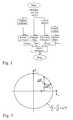
- the current wheel loadcan now preferably be determined from the deflection state of each wheel using the level sensors on the individual wheels according to the attached diagram according to FIG .
- the wheel load of each wheelcan thus be determined as precisely as desired by adding all four parts mentioned, as shown in FIG . 1 , with a force with the letter “F” and the vertical direction with the usual technical terminology Coordinate “z” is designated, while the letter “h” symbolizes a height or longitudinal extension in the z direction and the temporal differentiation is illustrated by a point above the size to be differentiated (here: h).
- the maximum possible tire forcesare now in the Determine horizontal plane between wheel / tire and road surface, and both in the longitudinal direction of the vehicle (identified by the coordinate "x") and in the vehicle transverse direction (identified by the coordinate "y").
- a coefficient of friction sensor for determining the coefficient of friction leaves between Wheel or tire and roadsignificantly improve accuracy expect, however, if such a coefficient of friction sensor is not used can be a previously known coefficient of friction estimate of an already known driving dynamics control system become.
- Such an estimation of the friction valueis, for example, also in the electronic stabilization programs that have recently become increasingly known (ESP or also called DS) included.
- each individual ellipse surface for the associated wheel loadindicates the maximum available adhesion potential, which - as shown in Fig.3a - results from the vectorial addition of the two horizontal components F x, max and F y, max .
- the adhesion limit of the individual tire (s) (or wheel)is now determined. For practical use, however, it is not this adhesion limit itself that is of interest, but the distance between the current operating point of the tire forces and this adhesion limit. So it is interested in the adhesion reserve that is still available at the current operating point, ie the adhesion potential still remaining, taking into account the current utilization of the adhesion.
- This adhesion reserveis formed (in the figurative representation of the so-called adhesion cone) by the shortest distance between the maximum available adhesion potential and the current adhesion utilization, i.e. between the outer surface of the adhesion cone and the current one operating point.
- This so-called adhesion reserveis now determined in a third calculation step, which is shown in principle in FIG .
- the instantaneous tire forcesare required for this, some of which are already known, namely in the form of the already determined wheel load F z , or which can be estimated (in the horizontal plane) in a known manner using the sensors mentioned.
- the oriented lateral force y in the transverse direction F ymay be approximately determined from the lateral and yaw acceleration and in Fzg. longitudinal direction x-oriented longitudinal force F x from the longitudinal acceleration or from the current output torque of the Fzg. drive apparatus, as well as from the current brake pressures can be determined.
- the already mentioned lateral acceleration and yaw rate sensoras well as the information about the wheel speeds are required, as well as suitable values from the control system of the vehicle drive unit and from the known brake pressure estimate of a known vehicle dynamics control system. If the determination of the respective forces is falsified, for example, by a slope of the road, suitable estimation methods can also be used for this, as are known in principle from the driving dynamics control.
- the respective adhesion reserves in x- and y-direction(namely ⁇ F x, max and ⁇ F y, max ) are determined.
- the vector ⁇ F z, maxleads from the lower plane of the ellipse to an ellipse above it, in which an operating point with these horizontal forces F x0 and F y0 lies exactly on the edge of the ellipse and thus fully utilizes the available adhesion potential.
- the currentcan be separately for each wheel
- Sufficient traction reservestaking into account all three dimensions exactly (and because of the consideration of vertical movements of the structure, above all, considerably more precisely than in the known prior art) be determined. Thereupon it is possible to determine these traction reserves to supply a so-called “adhesion controller", taking into account the desired driving maneuver a cheap use of the current adhesion offer.
- adhesion regulatoris a range of functions contained within a driving dynamics controller, for example referred to, which serves to optimize the adhesion.
- a systemcan be operated with it that not only the longitudinal forces in the longitudinal direction of the vehicle in initiates the horizontal plane between the wheel / tire and the road, but also a transverse dynamic and a vertical dynamic control system.
- additional chassis control functionsare, for example: an electronically controllable rear axle steering or a front axle overlay steering to name, where these two systems are transverse dynamic control systems.
- targeted Interventions in one or more vertical dynamic control systemsuch as in the form of an electronic damping force adjustment, one Stabilizer adjustment or an active suspension.
- the latter three Systemsare generally known per se, but have so far served primarily improving driving comfort. Because about this vertical dynamic Systems also have a direct influence on the wheel loads, they can also improve the driving behavior according to the invention and driving safety.
- a so-called adhesion controllercan not only the current adhesion offer determine, but also have the task of the respective Compare requirements of the systems involved and Prioritize their implementation. For example or preferred can / should take first place driving safety, after which in general good driving behavior can be valued and what is the last thing (with the least importance) can connect so-called comfort functions.
- braking operations initiated by the driver Priority over all other control functions; i.e. all control signals to the possible actuators, influenced the driving dynamicscan be, with regard to their effects on the adhesion checked and, if necessary, corrected such that a maximum braking deceleration is achieved.
- the vehicle during a Stability control in the curve braked by the drivercan Braking forces are distributed in such a way that next to the shortest possible Braking distance also sets a largely stable cornering behavior.
- a traction controlleris integrated in a basic system that already has a vehicle simulation model, such as in a driving dynamics controller.
- vehicle simulation modelsuch as in a driving dynamics controller.
- Thisusually uses a one- or two-lane calculation model, which - as has already been explained - evaluating the brake pressure sensor, signals from the control of the vehicle drive unit and a steering angle sensor, the longitudinal and transverse movement of the vehicle intended by the driver (i.e. the driver's request) with regard to speed, deceleration or acceleration as well as cornering), ie the so-called target driving state is determined.
- the simulatorrequires the most important vehicle-specific parameters such as center of gravity, moments of inertia, wheelbase, track width and slip resistance of the respective tires.
- FIG 6is such a (basically known) vehicle model, which determines the target vehicle state ( “target”), referred to as “transverse dynamic model” and is additionally provided with the reference numeral 60th
- the actual driving state(actual) is determined from the signals of the yaw rate sensor, the lateral acceleration sensor and the wheel speeds.
- the actual driving state "actual”is then compared with the target driving state "target” in a module provided with reference number 62 and called “yaw moment controller". If the two differ from one another, a compensation torque is calculated in the yaw moment controller 62 in a manner known per se.
- the forces F x, i F y, i F z, i mentionedcan also be measured directly, provided suitable force sensors are available (for example, with the tire deformation as a measured variable), which is shown in FIG. 6 is that in addition to the level, these three forces are set in parentheses as input signals for module 63.
- These traction reserves ⁇ F x, i , ⁇ F y, i and ⁇ F z, ican then be fed directly to so-called priority modules 65 to 68 and / or to the (known) yaw moment controller 62.
- the traction reserves ⁇ F x, i , ⁇ F y, i , and ⁇ F z, iare supplemented by prediction values which are obtained with the aid of a module 69, which is referred to as "vertical dynamic simulation".
- the vibration behavior of the vehicleis simulated in this module 69 and the vehicle reaction is predetermined, insofar as the available sensors allow it.
- the vehicle's braking behavior and starting maneuversare used to calculate its pitching behavior, the steering behavior, the roll behavior and the height-level signals, the stroke-vibration behavior of the body and the expected effects on the longitudinal forces F x, i , on the lateral forces F y, i and on the vertical forces F z, i are estimated.
- a special functional qualityis achieved if these estimated values are additionally supported by forward-looking sensors (for example a coefficient of friction sensor on the front of the vehicle to determine the coefficient of friction ⁇ ), which is shown in FIG. 6 by the corresponding input variable ⁇ for the module 69 in parentheses.
- forward-looking sensorsfor example a coefficient of friction sensor on the front of the vehicle to determine the coefficient of friction ⁇
- priority modules 65, 66, 67, 68already briefly mentioned each for the relevant actuators for the control system applying longitudinal forces and for the transverse dynamic control system and for the vertical dynamic Control system of the vehicle the different functional requirements collected and sorted by priority. As in the introductory Description has already been explained, it is the longitudinal forces applying control system to control the brake pressure, what a Module 65 (“priority brake pressure”) is provided, as well as the control the output torque of the vehicle drive unit, for which a module 66 (“Engine torque priority”) is provided.
- a transverse dynamic control systemworks, for example, with interventions in the vehicle steering, for which a module 67 ("Priority steering angle") is provided while a vertical dynamic Control system - as already mentioned - preferably in the individual wheel Suspension and damping intervenes and / or the behavior of the chassis stabilizer suitably varied. There is a module for these latter interventions 68 ("Priority vertical force”) responsible.
- the driver request and the requirements from a conventional ABS software modulewhich is still present can also be set in the priority module 65 ("priority brake pressure") from a so-called ASC / ASR module (this is a so-called automatic stability control or traction control system).
- priority brake pressurea so-called ASC / ASR module
- Priority circuits of this typeare known from vehicle dynamics controllers for brake pressure control.
- control signals to the corresponding actuatorsare now checked in the priority modules 65 to 68 on the basis of the estimated values for the traction reserves ⁇ F x, i , ⁇ F y, i and ⁇ F z, i for feasibility and, if necessary, directly to the yaw moment controller 62 or other affected controllers returned.
- the second direct path of the estimated values for the traction reserves ⁇ F x, i , ⁇ F y, i and ⁇ F z, i from the module 64 (“traction reserves”) to the yaw moment controller 62, which is shown in FIG . 6 ,is not absolutely necessary, but is helpful in order to Maintain driving stability with the best possible driving comfort.
- interventionsare also to take place, for example, via steering systems and / or vertical dynamics systems , the estimated values for the traction reserves ⁇ F x, i , ⁇ F y, i and ⁇ F z, i the optimal actuator for the respective driving situation.
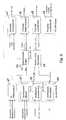
- FIG. 7in which a so-called superimposed force control regulator is shown, that is to say a force control regulator which suitably controls the control systems involved and is superimposed on various existing vehicle control systems.
- a superimposed non-positive regulatoris preferably used when the non-positive connection is also to be subsequently optimized in a fully developed control system or in a network of control systems. Since this function is not already integrated in the basic function, additional effort is inevitably required, which may cost additional computing time.
- FIG. 7shows an example of such a system network, in which several longitudinally dynamic, transverse dynamic and vertical dynamic control systems are networked with one another.
- this figure representationshows how the different control functions are integrated into the driver / vehicle control circuit.
- the driver's controls for his most important driving activities(braking, accelerating and steering) are listed on the left; on the right are the actuators which he actuates and which he uses to determine the driving behavior of the vehicle. (The vehicle drive unit is labeled "engine").
- the functions 71 influencing the "comfort”either assist the driver in his activities (such as servo brakes or power steering) or ensure optimum driving comfort by influencing the vertical forces.
- comfort module 71in addition to the (pneumatic or hydraulic) servo brake with the dynamic brake control "DBC”, an additional electronic support function is also listed, which enables extremely rapid brake pressure build-up, especially in emergency braking situations, and does this by changing the driver's request read the rate of increase in brake pressure.
- Your brake pressure request(denoted by p DBC ) leads to the priority module 65 (“brake pressure”), which is also provided here and has already been explained in conjunction with FIG. 6.
- the functions of the engine control(digital engine electronics “DME” or digital diesel electronics “DDE”) and the (hydraulic or electric) power steering with the "Servotronic” as an additional electronic function are located below the braking functions Dependence on the driving speed varies, so that a higher level of support is provided, especially when parking.
- the lower field of the comfort module 71shows the vertical dynamic control systems “EDC” (electronic damper control), the active suspension and the stabilizer adjustment "ACE” (Active Cornering Enhancement), which adjust the damper, spring and stabilizer forces depending on the driving situation. that optimum driving comfort is always ensured (including the highest possible set-up rest).
- the reference numeral 72denotes another module known per se, which exercises the so-called slip control functions. If the driver of the vehicle brakes harder or accelerates more than the current road conditions allow, it is known that the control systems "ABS” (anti-lock braking system) and “ASC” (automatic stability control) limit the brake or drive slip and control it in this way, that maximum longitudinal forces F x and lateral forces F y can be transmitted.
- ABSanti-lock braking system
- ASCautomatic stability control
- Reference number 73denotes a so-called driving behavior module, which contains, inter alia, the so-called cornering brake control "CBC".
- CBCcornering brake control
- Thisis a control function to improve driving stability when braking on bends, which generates a compensation torque due to different brake pressure build-up on the left / right, which counteracts the turning yaw reaction when cornering and has the output variable p CBC as brake pressure request.
- ⁇ CBCin the presence of a front axle superimposed steering, which superimposes an additional steering angle on the driver's steering request, or with a rear axle steering, the required compensation torque can be amplified via corresponding steering locks.
- R CBCtargeted wheel load changes
- the yaw moment control GMR that is still present in this module 73is basically the core function of vehicle dynamics controls, the above i.V.m. Fig. 6 has already been explained in detail.
- Thiscan be a superimposed steering on the front axle (VAL) and / or a rear axle steering (HAL) can also be used to optimize driving stability, provided that - as shown in Fig. 7 - on the same input variables as the yaw moment controller GMR.
- the system network shown in Fig . 7is a maximum configuration of chassis control functions.
- the adhesion control according to the inventioncan of course also be used with reduced functional scope, just as with a reduced number of sensors. Then the missing signals have to be replaced by plausible estimates.
- the procedure describedcan be used to calculate in advance how much a wheel is individually braked, steered or relieved until the horizontal tire forces reach their limit, and thus the actions of the driver or a control system have no effect become or the vehicle becomes uncontrollable.
- Thiswill make the Control quality of a vehicle dynamics control system (or others with each other linked longitudinal, transverse or vertical dynamic systems) better and more reliable.
- the driving dynamics limitsare expanded Driving safety as well as driving performance improved and the design scope Enlarged for comfort optimizations, although still pointed out be that quite a lot of details differ from the above Explanations can be designed without the content of the claims leave.
Landscapes
- Engineering & Computer Science (AREA)
- Mechanical Engineering (AREA)
- Transportation (AREA)
- Automation & Control Theory (AREA)
- Chemical & Material Sciences (AREA)
- Combustion & Propulsion (AREA)
- Physics & Mathematics (AREA)
- Mathematical Physics (AREA)
- Theoretical Computer Science (AREA)
- Regulating Braking Force (AREA)
- Vehicle Body Suspensions (AREA)
- Control Of Driving Devices And Active Controlling Of Vehicle (AREA)
Abstract
Description
Translated fromGermanDie Erfindung betrifft ein Fahrdynamik-Regelsystem eines insbesondere vierrädrigenKraftfahrzeuges, wobei das zwischen Rädern und Fahrbahn zurVerfügung stehende Kraftschlußpotential durch ein Rechenverfahren ermitteltwird und unter Berücksichtigung hiervon ein Längskräfte auf die Fahrzeugräderaufbringendes Regelsystem geeignet betrieben wird. Zum technischenUmfeld wird neben der DE 198 22 481 A1 auf die DE 42 00 997 A1verwiesen.The invention relates to a driving dynamics control system, in particular a four-wheeled vehicleMotor vehicle, which between the wheels and the road toThe available adhesion potential is determined by a calculation methodand taking into account a longitudinal force on the vehicle wheelsapplicable control system is operated appropriately. For technicalThe environment is next to DE 198 22 481 A1 to DE 42 00 997 A1directed.
Bekannte Systeme zur Aufrechterhaltung der Fahrstabilität können unterdem Begriff "Fahrdynamikregelung" subsumiert werden und berücksichtigenim allgemeinen den querdynamischen und längsdynamischen Zustand einesFahrzeuges. Dieser Zustand soll dann durch aktive Eingriffe z.B. in dieLenkanlage und/oder Bremsanlage und/oder Antriebsanlage des Kraftfahrzeugesgeeignet beeinflusst werden. So beschreibt bspw. die genannteDE 198 22 481 A1 eine Fahrstabilitäts-Steuerungsvorrichtung für ein Fahrzeug,das ein vorderes rechtes, ein vorderes linkes, ein hinteres rechtes undein hinteres linkes Rad sowie ein Bremssystem zur wahlweisen separatenBremsung eines jeden der Räder hat. Die Steuerungsvorrichtung schätztdann ein Verhältnis einer Längskraft zu einer Vertikallast, die auf jedes derRäder wirkt, ab, und betätigt bei einem gewünschten Bremsvorgang dasFzg.-Bremssystem derart, daß das genannte Verhältnis an jedem Rad einenim wesentlichen gleichen Wert einnimmt.Known systems for maintaining driving stability can be found underthe term "driving dynamics control" subsumed and take into accountgenerally the transverse dynamic and longitudinal dynamic state of aVehicle. This condition should then be activated through active interventions e.g. in theSteering system and / or brake system and / or drive system of the motor vehiclebe influenced appropriately. So describes, for exampleDE 198 22 481 A1 a driving stability control device for a vehicle,that a front right, a front left, a back right anda rear left wheel and a braking system for optional separateBraking of each of the wheels. The control device estimatesthen a ratio of a longitudinal force to a vertical load applied to each of theWheels acts, off, and actuates the when braking is desiredVehicle braking system in such a way that the stated ratio is one on each wheeltakes essentially the same value.
In der eingangs ebenfalls genannten DE 42 00 997 A1 ist ein Verfahren zurErmittlung der fahrdynamischen Sicherheitsreserve eines Kraftfahrzeugesbeschrieben. Dieses ist mit einem Lenkwinkelsensor, mit Beschleunigungssensorensowie mit einem Raddrehzahlsignale liefernden ABS-Gerät ausgerüstet.Zur Ermittlung der fahrdynamischen Sicherheitsreserve werden imSteuergerät zuerst aus der Querbeschleunigung und dem Lenkwinkel einKraftschlußwert in Querrichtung, und dann aus der Raddrehbeschleunigungund der Längsbeschleunigung ein Kraftschlußwert in Längsrichtung ermittelt.Aus diesen beiden Kraftschlußwerten wird eine maximal erreichbare Längsbeschleunigungdurch Multiplikation mit fahrzeugspezifischen Koeffizientenermittelt, woraus dann eine Grenzkurve gebildet wird, mit welcher die aktuelleQuer- und Längsbeschleunigung des Fahrzeugs verglichen wird, um diefahrdynamische Sicherheitsreserve zu ermitteln.DE 42 00 997 A1, which was also mentioned at the beginning, describes a method forDetermination of the dynamic driving safety reserve of a motor vehicledescribed. This is with a steering angle sensor, with acceleration sensorsand equipped with an ABS device delivering wheel speed signals.To determine the driving dynamics safety reserve inControl unit first from the lateral acceleration and the steering angleTraction value in the transverse direction, and then from the wheel spinand the longitudinal acceleration is determined in the longitudinal direction.A maximum achievable longitudinal acceleration becomes from these two adhesion valuesby multiplication with vehicle-specific coefficientsdetermined, from which a limit curve is then formed, with which the currentLateral and longitudinal acceleration of the vehicle is compared to theto determine the driving dynamics safety reserve.
Ist nun mit - für geringere Anforderungen - ggf. bereits ausreichender Genauigkeitdas vorhandene Kraftschlußpotential, d.h. die soeben genanntefahrdynamische Sicherheitsreserve bekannt, so gilt es, diese in einem Fahrdynamik-Regelsystemnach dem Oberbegriff des Anspruchs 1 bestmöglichzu nutzen, was mit der vorliegenden Erfindung aufgezeigt werden soll (=Aufgabe der vorliegenden Erfindung).Is now with - for lower requirements - possibly sufficient accuracythe existing adhesion potential, i.e. the one just mentionedDynamic safety reserve known, so it is important in a driving dynamics control systembest possible according to the preamble of claim 1to use what should be shown with the present invention (=Object of the present invention).
Die Lösung dieser Aufgabe ist dadurch gekennzeichnet, daß zusätzlich einquerdynamisches Regelsystem, welches Seitenkräfte in die Räder einleitetund/oder ein vertikaldynamisches Regelsystem, welches die in Vertikalrichtungorientierte Radlast ändert, derart betrieben wird, dass dasKraftschlusspotential weitgehend ausgenutzt werden kann. VorteilhafteWeiterbildungen sind Inhalt der Unteransprüche.The solution to this problem is characterized in that an additionaltransverse dynamic control system which introduces lateral forces into the wheelsand / or a vertical dynamic control system, which in the vertical directionoriented wheel load changes, is operated such that theTraction potential can be largely exploited. advantageousFurther training is the content of the subclaims.
Erfindungsgemäß wird somit zur Optimierung des Kraftschlusses nicht nurein an sich bekannter, bislang üblicher Fahrdynamikregler herangezogen,der durch geeignete Eingriffe in das Bremssystem und/oder in die Steuerungdes Fzg.-Antriebsaggregates stabilisierende Einflüsse in den einzelnen Radaufstandsebenenbewirkt bzw. die dort in der Horizontalebene zu übertragendenLängskräfte derart beeinflußt, daß ausreichende Fahrstabilität gewährleistetist, sondern es erfolgt zusätzlich eine geeignete Verknüpfung mitweiteren Fahrwerk-Regelfunktionen, wie z.B. mit einer elektronisch regelbarenHinterachslenkung oder einer Vorderachs-Überlagerungslenkung, wobeies sich bei diesen beiden Systemen um querdynamische Regelsystemehandelt, die Seitenkräfte ebenfalls in der Horizontalebene zwischenRad/Reifen und Fahrbahn einleiten.According to the invention, this is not only used to optimize the frictional connectiona vehicle dynamics controller that is known per se and used until now,by suitable interventions in the braking system and / or in the controlstabilizing influences in the individual wheel contact levelscauses or those to be transmitted there in the horizontal planeLongitudinal forces are influenced in such a way that sufficient driving stability is guaranteedis, but there is also a suitable link withother chassis control functions, e.g. with an electronically controllableRear axle steering or a front axle superposition steering, whereinthese two systems are transverse dynamic control systemsacts, the lateral forces also in the horizontal plane betweenIntroduce wheel / tire and roadway.
Anstelle eines (oder mehrerer) querdynamischen Regelsystemes oder auchzusätzlich zu diesem (oder diesen) kann eine Verknüpfung mit einem odermehreren vertikaldynamischen Regelsystemen erfolgen, wie z.B. mit einerelektronischen Dämpfkraftverstellung, einer Stabilisatorverstellung oder eineraktiven Federung, die - an sich bekannt - bislang vornehmlich der Verbesserungdes Fahrkomforts dienen, und die Vertikalkräfte in das System Rad-Fahrbahneinbringen können. Da sich über diese Systeme in Vertikalrichtungzwischen den Rädern und der Fahrbahn die Radlasten (nämlich die Vertikalkräfte)direkt beeinflussen lassen, können diese Regelsysteme in besonderseffizienter Weise auch zur Verbesserung des Fahrverhaltens und der Fahrsicherheitherangezogen werden.Instead of one (or more) transverse dynamic control system orin addition to this (or these) can be linked with an orseveral vertical dynamic control systems, such as with aelectronic damping force adjustment, stabilizer adjustment or oneactive suspension, which - known per se - so far mainly the improvementof driving comfort, and the vertical forces in the wheel-lane systemcan bring. Because of these systems in the vertical directionbetween the wheels and the road surface the wheel loads (namely the vertical forces)can influence directly, these control systems in particularefficient way to improve driving behavior and driving safetybe used.
Insgesamt können somit mit gezielten Eingriffen in die Steuerung des Antriebsaggregatessowie in das Bremssystem die Längskräfte und mit weiterenEingriffen bspw. in das Lenkungssystem des Kraftfahrzeuges die Querkräfteund/oder mit (noch) weiteren Eingriffen in ein in Vertikalrichtung wirkendesSystem die einzelnen Radlasten an den einzelnen Rädern derart gezielt geändert und dabei derart aufeinander abgestimmt werden, daß dasvorhandene Kraftschlußpotential optimal oder quasioptimal, d.h. weitgehendausgenutzt werden kann. In bestimmten (ansonsten kritischen) Fahrsituationen,in denen ein entsprechender Bedarf besteht, wird somit angestrebt,durch ein vertikaldynamisches und/oder ein querdynamsiches Regelsystemzusätzlich zum Längskräfte auf die Fahrzeugräder aufbringenden Regelsystemdas zur Verfügung stehende Kraftschlusspotential in weitgehend optimalerWeise auszunutzen.Overall, targeted interventions in the control of the drive unit are therefore possibleas well as in the braking system the longitudinal forces and with othersIntervening in the steering system of the motor vehicle, for example, the lateral forcesand / or with (still) further interventions in a vertical oneSystem so the individual wheel loads on the individual wheelsdeliberately changed and coordinated in such a way that theexisting adhesion potential optimal or quasi-optimal, i.e. largelycan be exploited. In certain (otherwise critical) driving situations,in which there is a corresponding need, the aim isthrough a vertically dynamic and / or a transverse dynamic control systemin addition to the control system applying longitudinal forces to the vehicle wheelsthe available adhesion potential is largely optimalWay to exploit.
Im Sinne einer vorteilhaften Weiterbildung der Erfindung wurde erkannt, daßmögliche Eingriffe bspw. in das Bremssystem oder in die Antriebsregelungdes Kraftfahrzeuges zur Aufrechterhaltung der Fahrstabilität nur dann wirksamwerden können, wenn zwischen den Rädern bzw. Reifen und der Fahrbahnein ausreichendes Kraftschlußpotential zur Verfügung steht. Letzteresist bekanntermaßen für jedes Rad eines bspw. vierrädrigen Kraftfahrzeugesvon der individuellen Radlast in Vertikalrichtung abhängig, d.h. von der individuellenRadaufstandskraft, die im fahrdynamischen Zustand starken Änderungenunterworfen ist.In the sense of an advantageous development of the invention, it was recognized thatpossible interventions, for example in the braking system or in the drive controlof the motor vehicle to maintain driving stability only then effectivecan be if between the wheels or tires and the roadsufficient adhesion potential is available. The latteris known for each wheel of a four-wheel motor vehicle, for exampledependent on the individual wheel load in the vertical direction, i.e. from the individualWheel contact force, the strong changes in driving dynamicsis subject.
Im bekannten Stand der Technik wird diese Tatsache nicht oder nur unzureichendberücksichtigt, d.h. es wird nicht erkannt, ab wann die Reifen keinegrößeren Kräfte mehr übertragen können, wenn ein Rad gelenkt, gebremstoder angetrieben wird. Daher wird in den bekannten Fahrdynamik-Regelsystemenauch nicht erkannt, wann der Eingriff des Regelsystems keinenweiteren Effekt auf die Fahrzeugbewegung haben kann, nachdem die Kraftschlußgrenzeeines oder mehrerer Räder bereits erreicht ist.In the known state of the art, this fact is not or only insufficienttaken into account, i.e. it is not recognized when the tires do not startlarger forces can transmit more when a wheel is steered, brakedor driven. Therefore, in the known driving dynamics control systemsalso not recognized when the intervention of the control system nonemay have further effect on vehicle movement after the adhesion limitone or more wheels has already been reached.
Dabei stellt sich diese zusätzliche Problematik insbesondere dann, wennunterschiedliche Fahrwerk-Regelsysteme vorgesehen sind, die parallel zueinanderdas Fahrzeug-Fahrverhalten beeinflussen können, ohne dabei direkt funktional miteinander verknüpft zu sein. Beispiele für derartige unterschiedlicheFahrwerk-Regelsysteme sind die bereits genannten querdynamischenund vertikaldynamischen Systeme, die sich im bekannten Stand derTechnik bei der an sich gewünschten Ausnutzung des Kraftschlußpotentialsdurchaus gegenseitig behindern oder in ihrer Wirkung neutralisieren können.This additional problem arises especially whenDifferent chassis control systems are provided that are parallel to each othercan influence the vehicle driving behavior without doing so directlyto be functionally linked. Examples of such differentChassis control systems are the cross-dynamic already mentionedand vertical dynamic systems, which are in the known state of the artTechnology in the desired exploitation of the adhesion potentialcan hinder each other or neutralize their effect.
In einer bevorzugten Ausführungsform der Erfindung kann zur Lösung dieserweiteren Problematik vorgesehen sein, daß in die besagte Berechnung desKraftschlußpotentials (die im Oberbegriff des Anspruchs 1 angegeben ist)neben den in der Horizontalebene zwischen den Rädern und der Fahrbahnübertragenen Kräften zusätzlich die in Vertikalrichtung orientierte Radlast miteingeht. In einer besonders vorteilhaften Weiterbildung ist hierfür an jedemRad ein Aufbau-Höhenstandssensor vorgesehen, aus deren Signalen die inVertikalrichtung orientierte Radlast auf relativ einfache Weise ausreichendgenau bestimmbar ist, wie an späterer Stelle noch ausführlich erläutert wird.In a preferred embodiment of the invention, this can be achievedfurther problem can be provided that in the said calculation of theAdhesion potential (which is specified in the preamble of claim 1)next to those in the horizontal plane between the wheels and the roadtransmitted forces also the wheel load oriented in the vertical directionreceived. In a particularly advantageous further development, everyone is responsible for thisWheel a body level sensor is provided, from whose signals the inSufficiently simple vertical load is sufficientcan be precisely determined, as will be explained in detail later.
Zur Verbesserung des Fahrverhaltens und der Fahrsicherheit wird somit vorgeschlagen,das Kraftschlußpotential zwischen Reifen und Fahrbahn optimalauszunutzen, wozu das jeweils vorhandene Kraftschlußpotential durch einRechenverfahren ermittelt wird, welches die Signale diverser Fahrwerksensorensowie fahrwerkspezifische Kenndaten des Fahrzeugs verarbeitet.To improve driving behavior and driving safety, it is therefore proposed thatthe adhesion potential between the tire and the road is optimalto take advantage of what the existing adhesion potential through aCalculation process is determined, which signals the various chassis sensorsas well as chassis-specific characteristics of the vehicle.
Im weiteren wird ein erfindungsgemäßes Fahrdynamik-Regelsystem im Sinneeines bevorzugten Ausführungsbeipieles für ein vierrädriges Kraftfahrzeug,insbesondere einen Personenkraftwagen, erläutert, der/das mit einemder bekannten Fahrdynamikregelsysteme und einer beliebigen Zweiachs-Niveauregulierungausgestattet ist. Bekanntermaßen erlaubt es eine derartigeZweiachs-Niveauregulierung, den Höhenstand des Aufbaus gegenüberder Fahrbahn radindividuell zu verändern, d.h. für jede - bevorzugt als Einzelradaufhängungausgebildete - Radaufhängung kann der Abstand zwischen dem Bodenblech der Fzg.-Karosserie und dem Rad in gewissen Bereichenbeliebig eingestellt werden. Erfindungswesentlich können dabeisämtliche näher beschriebenen Merkmale sein.Furthermore, a driving dynamics control system according to the invention is in the sensea preferred embodiment for a four-wheel motor vehicle,in particular a passenger car, which explains that with athe well-known driving dynamics control systems and any two-axis level controlIs provided. As is known, it allows suchTwo-axis level control, compared to the level of the bodyto change the road individually for each wheel, i.e. for everyone - preferably as independent suspensiontrained - wheel suspension can be the distance betweenthe floor panel of the vehicle body and the wheel in certain areascan be set arbitrarily. Essential to the invention can beall the features described in more detail.
An einem derartigen Fahrzeug, an welchem grundsätzlich die Möglichkeitgegeben sein muß, die in Fahrtrichtung orientierte (negative oder positive)Längsbeschleunigung sowie die in Querrichtung hierzu orientierte Querbeschleunigungzu messen, stehen im allgemeinen die folgenden Sensoren zurVerfügung:
- 4 Höhenstandssensoren zur Messung der Ein- und Ausfederwege desAufbaus an den einzelnen Radaufhängungen
- 4 Raddrehzahlfühler, d.h. die sog. ABS-Sensoren
- ein Drehraten- oder Giergeschwindigkeitssensor
- ein Querbeschleunigungssensor,
- ein Lenkwinkelsensor
- zumindest ein Bremsdrucksensor, sowie
- ein Drosselklappenwinkelsensor oder ein adäquates Signal aus der Steuerungselektronikdes Fzg.-Antriebsaggregates zur Ermittlung von dessenDrehmoment- oder Leistungsabgabe.
- 4 level sensors for measuring the deflection and rebound travel of the body on the individual wheel suspensions
- 4 wheel speed sensors, ie the so-called ABS sensors
- a rotation rate or yaw rate sensor
- a lateral acceleration sensor,
- a steering angle sensor
- at least one brake pressure sensor, as well
- a throttle valve angle sensor or an adequate signal from the control electronics of the vehicle drive unit to determine its torque or power output.
Dabei kann mit den drei letztgenannten Sensoren der Fahrerwunsch sensiertwerden, nämlich eine Lenkbewegung für eine gewünschte Kurvenfahrt sowieBremsen und "Gasgeben" für eine gewünschte negative oder positive Beschleunigungin Fzg.-Längsrichtung. Mit den davor genannten Sensorenhingegen kann das Fahrverhalten des Fahrzeugs als Resultat der Fahrervorgabefestgestellt werden. Durch Vergleich des somit festgestellten sog.Ist-Fahrzustands mit einem aus dem sensierten Fahrerwunsch ermitteltensog. Soll-Fahrzustand kann daraufhin ein Fahrdynamik-Regelsystem in ansich bekannter Weise feststellen, ob sich das Fahrzeug noch auf stabilemThe driver's request can be sensed with the three last-mentioned sensorsbe, namely a steering movement for a desired cornering as wellBraking and "accelerating" for a desired negative or positive accelerationin the longitudinal direction of the vehicle. With the sensors mentioned beforeon the other hand, the driving behavior of the vehicle as a result of the driver specificationbe determined. By comparing the so-calledActual driving status with a determined from the sensed driver requestThe so-called target driving state can then be a driving dynamics control system indetermine in a known manner whether the vehicle is still stable
Kurs befindet oder ob die Aktuatorik des Regelsystems bspw. durch Eingriffein das Bremssystem oder in die Steuerung des Fzg.-Antriebsaggregateskorrigierend tätig werden muß.Course is or whether the actuators of the control system, for example, by interventionsin the braking system or in the control of the vehicle drive unitmust take corrective action.
Ergänzend zu diesem bekannten Stand der Technik kann nun bevorzugtüber die an den einzelnen Rädern vorhandenen Höhenstandssensoren gemäßder beigefügten Diagramm-Darstellung nachFig.1 aus dem Einfederungszustandeines jeden Rades dessen aktuelle Radlast ermittelt werden.In addition to this known state of the art, the current wheel load can now preferably bedetermined from the deflection state of each wheel using thelevel sensors on the individual wheels according to the attached diagram according toFIG .
Hierfür sind die selbstverständlich bekannten Kennlinien der Aufbau-Federelemente,über welche sich der Fzg.-Aufbau in Vertikalrichtung auf denRädern abstützt, sowie die zugeordneten Stabilisatorraten und ggf. dieKennlinien der ebenfalls wie üblich vorgesehenen Stoßdämpfer zu berücksichtigen.Im einzelnen kann, wenn die Radhübe der einzelnen Räder bekanntsind, zunächst der darin enthaltene Anteil der Radlast errechnet werden,der sich aufgrund des gleichseitigen Einfederns ergibt. Bei Beachtungder Radhubdifferenz der Räder einer Achse des Fahrzeuges wird der Anteilaufgrund wechselseitigen Einfederns bestimmt. Um die dynamischen Kräftezu berücksichtigen, kann zusätzlich noch die Radhubgeschwindigkeit gebildetwerden, und zwar durch zeitliche Differentiation des Höhenstandssensorsignals,die dann zusammen mit der Dämpferkennlinie und zugehörigerÜbersetzung die Dämpferkraft ergibt. Durch weitere Differentiation kanndurch Bestimmen der Radhubbeschleunigung auch noch die Trägheitskraftder sog. ungefederten Masse einfließen.For this are the naturally known characteristics of the body spring elements,over which the vehicle structure in the vertical direction on theSupports wheels, as well as the assigned stabilizer rates and, if applicable, theCharacteristics of the shock absorbers, which are also provided as usual, must be taken into account.In particular, if the wheel strokes of the individual wheels are knownare first calculated the proportion of the wheel load contained therein,which results from the equilateral deflection. With attentionThe wheel stroke difference of the wheels of an axle of the vehicle becomes the proportiondetermined due to mutual deflection. To the dynamic forcesthe wheel lifting speed can also be taken into accountthrough time differentiation of the level sensor signal,which then together with the damper characteristic and associatedRatio gives the damper force. Through further differentiationthe inertia force by determining the wheel stroke accelerationthe so-called unsprung mass.
Auf die beschriebene Weise kann somit die Radlast eines jeden Radesdurch Addition aller vier genannten Anteile beliebig genau bestimmt werden,so wie dies inFig.1 dargestellt ist, wobei der üblichen Fachterminologie entsprechendeine Kraft mit dem Buchstaben "F" und die Vertikalrichtung mitder Koordinate "z" bezeichnet ist, während der Buchstabe "h" eine Höhe oder Längserstreckung in z-Richtung symbolisiert und die zeitliche Differentiationdurch einen Punkt über der zu differenzierenden Größe (hier: h) verdeutlichtist.In the manner described, the wheel load of each wheel can thus be determined as precisely as desired by adding all four parts mentioned, as shown inFIG .1 , with a force with the letter "F" and the verticaldirection with the usual technical terminology Coordinate "z" is designated, while the letter "h" symbolizes a height or longitudinal extension in the z direction and the temporal differentiation is illustrated by a point above the size to be differentiated (here: h).
In einem zweiten Schritt sind nun die maximal möglichen Reifenkräfte in derHorizontalebene zwischen Rad/Reifen und Fahrbahn zu bestimmen, undzwar sowohl in Fzg.-Längsrichtung (gekennzeichnet durch die Koordinate"x") als auch in Fzg.-Querrichtung (gekennzeichnet durch die Koordinate "y").In a second step, the maximum possible tire forces are now in theDetermine horizontal plane between wheel / tire and road surface, andboth in the longitudinal direction of the vehicle (identified by the coordinate"x") and in the vehicle transverse direction (identified by the coordinate "y").
Da hierfür eine relativ gute Kenntnis der Reifeneigenschaften (möglichst inForm eines Reifenkennfelds) sowie der Fahrbahnbeschaffenheit erforderlichist, wird die Bestimmung mit dem o.g. Einsatz an Sensoren relativ schwierig.Grundsätzlich läßt ein Reibwertsensor zur Ermittlung des Reibwertes zwischenRad bzw. Reifen und Straße eine deutliche Verbesserung der Genauigkeiterwarten, falls jedoch nicht auf einen solchen Reibwertsensor zurückgegriffenwerden kann, so kann eine grundsätzlich bereits bekannte Reibwertschätzungeines bereits bekannten Fahrdynamikregelungs-Systems herangezogenwerden. Eine solche Reibwertschätzung ist bspw. auch in den injüngerer Zeit vermehrt bekannt gewordenen elektronischen Stabilisierungsprogrammen(ESP oder auch DS genannt) enthalten.Since this requires a relatively good knowledge of the tire properties (if possible inShape of a tire map) and the condition of the road surfaceis the determination with the above Use on sensors relatively difficult.In principle, a coefficient of friction sensor for determining the coefficient of friction leaves betweenWheel or tire and road significantly improve accuracyexpect, however, if such a coefficient of friction sensor is not usedcan be a previously known coefficient of friction estimateof an already known driving dynamics control systembecome. Such an estimation of the friction value is, for example, also in theelectronic stabilization programs that have recently become increasingly known(ESP or also called DS) included.
Zusammen mit der in beschriebener Weise bereits bestimmten Radlast Fzkann nun zusammen mit einem gemessenen oder geeignet geschätztenReibwert (wie üblich mit dem griechischen Buchstaben "µ" bezeichnet) ermitteltoder zumindest hinreichend genau abgeschätzt werden, welche Horizontalkräftevom Rad bzw. Reifen maximal auf die Fahrbahnoberfläche übertragenwerden können.Together with the wheel load Fz already determined in the manner described, it can now be determined together with a measured or suitably estimated coefficient of friction (as usual with the Greek letter "µ"), or at least can be estimated with sufficient accuracy which maximum horizontal forces exerted by the wheel or tire the road surface can be transferred.
Im Folgenden wird beispielhaft zur Vereinfachung der Rechnung die durchausübliche Annahme getroffen (vgl. diesbezüglich auch den eingangs zitierten druckschriftlichen Stand der Technik), daß das sog. Reifenkennfeld - wiein der beigefügtenFig.2 dargestellt - durch Ellipsen angenähert werdenkann, nämlich in Form der sog. "Kraftschlußellipse". Dabei sei im folgendendie in x-Richtung (Längsrichtung) liegende Ellipsen-Halbachse mit demBuchstaben "a" und die in y-Richtung (Querrichtung) liegende Ellipsen-Halbachsemit dem Buchstaben "b" bezeichnet.In the following, the quite common assumption is made, for example, to simplify the calculation (cf. in this regard also the printed prior art cited at the beginning) that the so-called tire map - as shown in the attachedFIG . 2 - can be approximated by ellipses, namely in Form of the so-called "adhesion ellipse". In the following, the elliptical semiaxis lying in the x direction (longitudinal direction) is designated by the letter "a" and the ellipse semiaxis lying in the y direction (transverse direction) by the letter "b".
Sollen nun wie vorgeschlagen Vertikalbewegungen des Kraftfahrzeug-Aufbausgegenüber den Rädern in die Berechnung des Kraftschlußpotentialsmit eingehen, welche zu Radlastschwankungen (in Vertikalrichtung z) führen,so ist theoretisch jeder möglichen Radlast eine eigene Ellipse zuzuordnen,wobei die Flächen der Ellipsen mit steigender Radlast zunehmen. In einemdreidimensionalen Koordinatensystem, bei welchem die zwischen Rad undFahrbahn übertragenen Horizontalkräfte die beiden Ellipsenachsen definierenund die darauf senkrecht stehende dritte Achse durch die Vertikalkraft(zwischen Rad und Fahrbahn) beschrieben wird, können nun diese Ellipsenunterschiedlicher Vertikalkräfte übereinander angeordnet werden, wodurchsich quasi als Hüllkörper ein Kegel mit elliptischer Grundfläche ergibt, der als"Kraftschluss-Kegel" bezeichnet werden kann. Zumindest gilt dies solange,wie die horizontalen Reifenkräfte sich näherungsweise durch einen linearenZusammenhang von der Radlast abbilden lassen, so wie dies inFig.3a dargestelltist. Der Öffnungswinkel dieses Kraftschlußkegels ergibt sich dabei-wiein der Figur angegeben - aus dem momentanen Reibwert µ, wobei auchersichtlich wird, daß sich mit abnehmenden µ proportional alle Ellipsenflächenverringern.If, as suggested, vertical movements of the motor vehicle body with respect to the wheels are now included in the calculation of the adhesion potential, which lead to wheel load fluctuations (in the vertical direction z), then theoretically every possible wheel load must be assigned its own ellipse, the surfaces of the ellipses increasing with increasing wheel load , In a three-dimensional coordinate system, in which the horizontal forces transmitted between the wheel and the lane define the two ellipse axes and the third axis perpendicular to it is described by the vertical force (between the wheel and the lane), these ellipses of different vertical forces can now be arranged one above the other as an enveloping body results in a cone with an elliptical base, which can be referred to as a "frictional cone". At least, this applies as long as the horizontal tire forces can be approximated by the wheel load through a linear relationship, as shown inFIG .3a . The opening angle of this frictional cone results - as indicated in the figure - from the instantaneous coefficient of friction µ, whereby it can also be seen that with decreasing µ all ellipse surfaces decrease proportionally.
Bei völlig exakter Betrachtungsweise wäre infolge der tatsächlichen Reifeneigenschaftendie Mantelfläche dieses Kraftschlußkegels entsprechend derNichtlinearitäten im Übergangsbereich gekrümmt, was auch in einem Rechenprogrammberücksichtigt werden kann. Für das folgende vereinfachte Rechenverfahren wird jedoch (zunächst noch) von einer geraden Mantelliniedes Kraftschlußkegels ausgegangen.If you look at it exactly, it would be due to the actual tire propertiesthe lateral surface of this adhesion cone corresponding to theNon-linearities in the transition area are curved, which is also the case in a computer programcan be taken into account. Simplified for the followingHowever, the calculation method is (initially) a straight surface linethe traction cone.
Im Detail gibt die Größe jeder einzelnen Ellipsenfläche für die jeweils zugehörigeRadlast das maximal zur Verfügung stehende Kraftschluss-Potentialan, welches sich - wie in Fig.3a dargestellt - durch vektorielle Addition derbeiden Horizontalkomponenten Fx,max und Fy,max ergibt. Mit der Kenntnis diesermaximalen Horizontalkräfte ist nun die Kraftschlussgrenze des oder dereinzelnen Reifen (oder Rades) bestimmt. Für den praktischen Gebrauch istjedoch nicht diese Kraftschlussgrenze selbst, sondern der Abstand des momentanenBetriebspunkts der Reifenkräfte von dieser Kraftschlussgrenzevon Interesse. Es interessiert also die im aktuellen Betriebspunkt noch vorliegendeKraftschluss-Reserve, d.h. das unter Berücksichtigung der aktuellenKraftschluss-Ausnutzung noch verbleibende Kraftschlusspotential. DieseKraftschluss-Reserve wird dabei (in der figürlichen Darstellung des sog.Kraftschluss-Kegels) durch den kürzesten Abstand zwischen dem maximalzur Verfügung stehendem Kraftschluss-Potential und der aktuellen Kraftschluss-Ausnutzunggebildet, d.h. zwischen der Mantelfläche des Kraftschluss-Kegelsund dem aktuellen Betriebspunkt. Diese sog. Kraftschluss-Reservewird nun in einem dritten Berechnungsschritt bestimmt, der prinzipiellinFig.4 dargestellt ist.In detail, the size of each individual ellipse surface for the associated wheel load indicates the maximum available adhesion potential, which - as shown in Fig.3a - results from the vectorial addition of the two horizontal components Fx, max and Fy, max . With the knowledge of these maximum horizontal forces, the adhesion limit of the individual tire (s) (or wheel) is now determined. For practical use, however, it is not this adhesion limit itself that is of interest, but the distance between the current operating point of the tire forces and this adhesion limit. So it is interested in the adhesion reserve that is still available at the current operating point, ie the adhesion potential still remaining, taking into account the current utilization of the adhesion. This adhesion reserve is formed (in the figurative representation of the so-called adhesion cone) by the shortest distance between the maximum available adhesion potential and the current adhesion utilization, i.e. between the outer surface of the adhesion cone and the current one operating point. This so-called adhesion reserve is now determined in a third calculation step, which is shown in principle inFIG .
Benötigt werden hierfür selbstverständlich die augenblicklichen Reifenkräfte,die jedoch teilweise, nämlich in Form der bereits bestimmten Radlast Fzschon bekannt sind, oder die sich (in der Horizontalebene) mit Hilfe der genanntenSensorik in bekannter Weise schätzen lassen. So kann die in Querrichtungy orientierte Seitenkraft Fy aus der Quer- und Gierbeschleunigungnäherungsweise bestimmt werden und die in Fzg.-Längsrichtung x orientierteLängskraft Fx aus der Längsbeschleunigung bzw. aus dem aktuellen Abgabe-Drehmomentdes Fzg.-Antriebsaggregates sowie aus den aktuellen Bremsdrücken ermittelt werden. Hierfür sind der bereits genannte Querbeschleunigungs-und Gierratensensor sowie die Informationen über dieRad-Drehzahen erforderlich und außerdem geeignete Werte aus dem Steuerungssystemdes Fzg.-Antriebsaggregates sowie aus der an sich bekanntenBremsdruckschätzung eines bekannten Fahrdynamikregelung-Systems.Falls dabei die Bestimmung der jeweiligen Kräfte z.B. durch eine Fahrbahnneigungverfälscht wird, so können auch hierfür geeignete Schätzverfahrenangewendet werden, wie sie aus der Fahrdynamikregelung grundsätzlichbekannt sind.Of course, the instantaneous tire forces are required for this, some of which are already known, namely in the form of the already determined wheel load Fz , or which can be estimated (in the horizontal plane) in a known manner using the sensors mentioned. Thus, the oriented lateral force y in the transverse direction Fy may be approximately determined from the lateral and yaw acceleration and in Fzg. longitudinal direction x-oriented longitudinal force Fx from the longitudinal acceleration or from the current output torque of the Fzg. drive apparatus, as well as from the current brake pressures can be determined. For this, the already mentioned lateral acceleration and yaw rate sensor as well as the information about the wheel speeds are required, as well as suitable values from the control system of the vehicle drive unit and from the known brake pressure estimate of a known vehicle dynamics control system. If the determination of the respective forces is falsified, for example, by a slope of the road, suitable estimation methods can also be used for this, as are known in principle from the driving dynamics control.
Nunmehr sind also die aktuellen Horizontalkräfte zwischen Rad/Reifen undFahrbahn sowie für jedes Rad einzeln die aktuelle Kraftschlußellipse - inKenntnis der Radlast/Vertikalkraft aus dem sog. Kraftschlußkegel abgeleitet-bekannt,so daß wesentlich genauer als im bekannten Stand der Technikeine Kraftschluss-Reserve als Differenz dieser beiden bekannten Werte bestimmtwerden kann. Diese Kraftschluss-Reserve kann dann herangezogenwerden, um ein Fahrdynamik-Regelsystem in günstiger Weise betreiben zukönnen, was an späterer Stelle noch näher erläutert wird.So now the current horizontal forces between wheel / tire andRoadway and for each wheel individually the current traction ellipse - inKnowledge of the wheel load / vertical force derived from the so-called adhesion cone, known,so that much more precisely than in the known prior arta traction reserve is determined as the difference between these two known valuescan be. This adhesion reserve can then be usedto operate a vehicle dynamics control system in a favorable mannercan, which will be explained in more detail later.
Zunächst sei jedoch eine vorteilhafte Weiterbildung der vorliegenden Erfindungbeschrieben, die das vorhandene Kraftschlußpotential quasi auf dieeinzelnen Koordinaten aufteilt. Von Interesse ist somit nicht nur der kürzesteAbstand des augenblicklichen Betriebspunktes bis zur Kraftschlußgrenzeinnerhalb der aktuellen Kraftschlußellipse, sondern auch die maximal möglicheÄnderung für jede der drei Kräfte Fx, Fy und Fz, und zwar jeweils innerhalbdes bereits erläuterten Kraftschlußkegels soweit, bis das Kraftschlußpotentialausgeschöpft ist. In anderen Worten ausgedrückt kann sodann ermitteltbzw. berücksichtigt werden, welches Kraftschlußpotential bspw. inLängsrichtung (x) noch vorhanden ist, nachdem sich die Radlast in Vertikalrichtung (Fz) verändert hat oder mittels einer geeigneten Maßnahme sogar ingeeigneter Richtung gezielt verändert wurde.First, however, an advantageous further development of the present invention is described, which quasi divides the existing adhesion potential between the individual coordinates. Of interest is therefore not only the shortest distance from the current operating point to the adhesion limit within the current engagement ellipse, but also the maximum possible change for each of the three forces Fx , Fy and Fz , within the already explained adhesion cone so far, until the adhesion potential is exhausted. In other words, it can then be determined or taken into account which adhesion potential is still present, for example in the longitudinal direction (x), after the wheel load has changed in the vertical direction (Fz ) or has been specifically changed in a suitable direction by means of a suitable measure.
Am Beispiel des beschriebenen und inFig.3a dargestellten Kraftschluss-Kegelsmit elliptischer Grundfläche ergeben sich die inFig.3b in Form vonGleichungen angegebenen maximal möglichen Änderungen für die Kräfte Fin den einzelnen Koordinaten-Richtungen x, y, z, wobei ausdrücklich daraufhingewiesen sei, dass eine derartige Berechnung lediglich als ein Ausführungsbeispielzu verstehen ist. Anhand vonFig.5 wird dieses Verfahren imfolgenden nochmals ausführlicher erläutert:Using the example of thefrictional cone with an elliptical base area described and shown inFIG .3a , the maximum possible changes for the forces F in the individual coordinate directions x, y, z given inFIG it should be noted that such a calculation is only to be understood as an exemplary embodiment. This method is explained in more detail below withreference to FIG. 5 :
Ausgehend von einem aktuellen Betriebspunkt auf der unteren Ellipse, derdurch die Vertikalkraftkomponente Fz0 sowie die Längskraft Fx0 und die SeitenkraftFy0 beschrieben ist - (diese Komponenten stellen die momentaneKraftschluss-Ausnutzung dar) -, werden einerseits die jeweiligen Kraftschlußreservenin x- und y-Richtung (nämlich ΔFx,max und ΔFy,max) bestimmt. Gleichzeitigwird angegeben, wie stark sich die Vertikalkraft noch ändern dürfte, bisdas Rad an seiner Kraftschluss-Grenze angelangt ist. Bspw. gibt inFig.5 derVektor ΔFz,max an, wie weit das Rad noch ausfedern dürfte, bis bei unverändertenHorizontalkräften das zur Verfügung stehende Kraftschluss-Potentialausgeschöpft ist. Wie ersichtlich führt der Vektor ΔFz,max von der unteren Ellipsen-Ebenezu einer darüber liegenden Ellipse, in welcher ein Betriebspunktmit diesen Horizontal-Kräften Fx0 und Fy0 exakt auf dem Ellipsenrandliegt und somit das zur Verfügung stehende Kraftschlußpotential vollständigausschöpft.Starting from a current operating point on the lower ellipse, which is described by the vertical forcecomponent Fz0 as well as the longitudinal force Fx0 and the lateral force Fy0 - (these components represent the current utilization of the adhesion) - on the one hand, the respective adhesion reserves in x- and y-direction (namely ΔFx, max and ΔFy, max ) are determined. At the same time, it indicates how much the vertical force is likely to change until the wheel reaches its adhesion limit. For example. inFIG. 5 the vector ΔFz, max indicates how far the wheel should still rebound until the available adhesion potential is exhausted with unchanged horizontal forces. As can be seen, the vector ΔFz, max leads from the lower plane of the ellipse to an ellipse above it, in which an operating point with these horizontal forces Fx0 and Fy0 lies exactly on theedge of the ellipse and thus fullyutilizes the available adhesion potential.
Auf die beschriebene Weise können somit für jedes Rad separat die aktuellenKraftschlussreserven unter Berücksichtigung aller drei Dimensionen ausreichendgenau (und wegen der Berücksichtigung der Vertikalbewegungen des Aufbaus vor allem erheblich genauer als im bekannten Stand der Technik)ermittelt werden. Daraufhin ist es möglich, diese ermittelten Kraftschlußreserveneinem sogenannten "Kraftschlußregler" zuzuführen, der unter Berücksichtigungdes gewünschten Fahrmanövers eine günstige Nutzung desaktuellen Kraftschlußangebotes veranlaßt.In the manner described, the current can be separately for each wheelSufficient traction reserves taking into account all three dimensionsexactly (and because of the consideration of vertical movementsof the structure, above all, considerably more precisely than in the known prior art)be determined. Thereupon it is possible to determine these traction reservesto supply a so-called "adhesion controller", taking into accountthe desired driving maneuver a cheap use of thecurrent adhesion offer.
Ehe hierauf näher eingegangen wird, sei noch darauf hingewiesen, daß fürFälle, in denen eine höhere Genauigkeit als gemäß der obigen Beschreibungberechnet erwünscht wird, sich die genannten Reifenkennfelder anstelledurch die sog. Kraftschluß-Ellipsen mathematisch durch Polynome in beliebigerGenauigkeit annähern lassen. Dann mutieren die Ellipsengleichungenin Fig. 3b zu Parabeln n-ter Ordnung und der bislang sog. Kraftschlußkegelläßt sich dann bspw. durch ein sog. dreidimensionales Polynom-Kennfelddarstellen. Ferner sei darauf hingewiesen, daß für die Beschreibung des erläutertenVerfahrens zur Ermittlung des Kraftschlußpotentials ein an sich bekannterFahrdynamikregler als Basissystem gewählt wurde, weil ein solcheri.a. mit den wichtigsten Sensoren ausgestattet ist, die zur Bestimmung desKraftschlusses erforderlich sind. Stattdessen können jedoch auch andereSysteme mit ähnlicher Sensorik zugrunde gelegt werden.Before going into details, it should be pointed out that forCases where higher accuracy than described aboveis calculated, the tire maps mentioned insteadthrough the so-called adhesion ellipses mathematically through polynomials in anyLet accuracy approximate. Then the ellipse equations mutatein Fig. 3b on n-order parabolas and the so-called adhesion conecan then be, for example, a so-called three-dimensional polynomial maprepresent. It should also be noted that for the description of the explainedMethod for determining the adhesion potential known per seVehicle dynamics controller was chosen as the basic system because of suchi.a. is equipped with the most important sensors for determining theAdhesion is required. However, others can insteadSystems with similar sensors are used.
An das soweit beschriebene System kann sich nun - wie bereits kurz erwähntwurde - ein sog. Kraftschlußregler anschließen, der unter Berücksichtigungeines gewünschten Fahrmanövers eine günstige Nutzung des aktuellenKraftschlußangebotes veranlaßt. Mit dem Begriff "Kraftschlußregler" wirdein bspw. innerhalb eines Fahrdynamikreglers enthaltener Funktionsumfangbezeichnet, der zur Optimierung des Kraftschlusses dient. Bevorzugt erfolgtnun in diesem Kraftschlußregler eine Priorisierung bzw. Aufteilung des berechnetenbzw. übermittelten Kraftschlußpotentials an die beteiligten Regelfunktionennach einem festgelegten Schlüssel.The system described so far can now - as already briefly mentionedwas - connect a so-called adhesion regulator, taking into accounta desired driving maneuver a cheap use of the current oneForce offer initiated. With the term "adhesion regulator" isa range of functions contained within a driving dynamics controller, for examplereferred to, which serves to optimize the adhesion. Preferably donenow a prioritization or division of the calculated in this adhesion controlleror transmitted adhesion potential to the control functions involvedaccording to a fixed key.
Wie weiter oben bereits erläutert wurde, kann damit ein System betriebenwerden, das nicht nur die in Fzg.-Längsrichtung verlaufenden Längskräfte indie Horizontalebene zwischen Rad/Reifen und Fahrbahn geeignet einleitet,sondern zusätzlich ein querdynamisches sowie ein vertikaldynamisches Regelsystem.Als derartige zusätzliche Fahrwerk-Regelfunktionen sind bspw.eine elektronisch regelbare Hinterachslenkung oder einer Vorderachs-Überlagerungslenkungzu nennen, wobei es sich bei diesen beiden Systemenum querdynamische Regelsysteme handelt. Zusätzlich sollen gezielteEingriffe in ein oder auch mehrere vertikaldynamische(s) Regelsystem(e)erfolgen, wie z.B. in Form einer elektronischen Dämpfkraftverstellung, einerStabilisatorverstellung oder einer aktiven Federung. Diese drei letztgenanntenSysteme sind an sich grundsätzlich bekannt, dienten jedoch bislang vornehmlichder Verbesserung des Fahrkomforts. Da sich über diese vertikaldynamischenSysteme jedoch auch die Radlasten direkt beeinflussen lassen,können sie erfindungsgemäß ebenfalls zur Verbesserung des Fahrverhaltensund der Fahrsicherheit herangezogen werden.As already explained above, a system can be operated with itthat not only the longitudinal forces in the longitudinal direction of the vehicle ininitiates the horizontal plane between the wheel / tire and the road,but also a transverse dynamic and a vertical dynamic control system.Such additional chassis control functions are, for example:an electronically controllable rear axle steering or a front axle overlay steeringto name, where these two systemsare transverse dynamic control systems. In addition, targetedInterventions in one or more vertical dynamic control system (s)such as in the form of an electronic damping force adjustment, oneStabilizer adjustment or an active suspension. The latter threeSystems are generally known per se, but have so far served primarilyimproving driving comfort. Because about this vertical dynamicSystems also have a direct influence on the wheel loads,they can also improve the driving behavior according to the inventionand driving safety.
Bevorzugt kann ein sog. Kraftschlußregler nicht nur das aktuelle Kraftschlussangebotermitteln, sondern zusätzlich die Aufgabe haben, die jeweiligenAnforderungen der beteiligten Systeme miteinander zu vergleichen undPrioritäten für ihre Umsetzung festzulegen. Beispielsweise bzw. bevorzugtkann/sollte an erster Stelle die Fahrsicherheit stehen, wonach allgemein aufein gutes Fahrverhalten Wert gelegt werden kann und woran sich als letztes(mit der geringsten Wichtigkeit) sog. Komfortfunktionen anschließen können.Preferably, a so-called adhesion controller can not only the current adhesion offerdetermine, but also have the task of the respectiveCompare requirements of the systems involved andPrioritize their implementation. For example or preferredcan / should take first place driving safety, after which in generalgood driving behavior can be valued and what is the last thing(with the least importance) can connect so-called comfort functions.
In diesem Sinne haben Bremsvorgänge, die vom Fahrer eingeleitet werden,Vorrang vor allen anderen Regelungsfunktionen; d.h. alle Stellsignale an diemöglichen Aktuatoren, über die Einfluß auf die Fahrdynamik genommenwerden kann, werden hinsichtlich ihrer Auswirkungen auf den Kraftschlußüberprüft und ggf. derart korrigiert, daß eine maximale Bremsverzögerung erzielt wird. Selbstverständlich können nach Möglichkeit daneben aber auchandere Funktionen mit erfüllt werden. Wird z.B. das Fahrzeug während einerStabilitätsregelung in der Kurve vom Fahrer stark abgebremst, können dieBremskräfte derart verteilt werden, daß sich neben dem kürzestmöglichenBremsweg auch ein weitgehend stabiles Kurvenverhalten einstellt. Darüberhinaus kann über die vertikaldynamischen Regelsysteme - in diesem Fallinsbesondere über die elektronische Stabilisatorverstellung - zusätzlich nochEinfluß auf die Radaufstandskräfte genommen werden, mit dem Ziel, dieRadlasten an diejenigen Räder zu verlagern, die den höchsten Kraftschlußbedarfhaben.In this sense, braking operations initiated by the driverPriority over all other control functions; i.e. all control signals to thepossible actuators, influenced the driving dynamicscan be, with regard to their effects on the adhesionchecked and, if necessary, corrected such that a maximum braking decelerationis achieved. Of course you can also if possibleother functions are fulfilled with. E.g. the vehicle during aStability control in the curve braked by the driver, canBraking forces are distributed in such a way that next to the shortest possibleBraking distance also sets a largely stable cornering behavior. About thatcan go beyond the vertical dynamic control systems - in this caseespecially via the electronic stabilizer adjustment - additionallyInfluence on the wheel contact forces are aimed at, theShifting wheel loads to those wheels that require the highest adhesionto have.
Wie bereits erwähnt, wird ein derartiger Funktionsumfang innerhalb einesansonsten an sich bekannten Fahrdynamikreglers, der das Kraftschlußangebotabschätzt und für eine optimale Nutzung sorgt, als Kraftschlußreglerbezeichnet. Ein derartiger erfindungsgemäßer Kraftschlußregler kann nunentweder von vornherein in der Systemarchitektur berücksichtigt sein odernachträglich, d.h. zu einem bereits existierenden Fahrdynamikregler hinzugefügtwerden.As already mentioned, such a range of functions is within aotherwise known driving dynamics controller, which offers the adhesionestimates and ensures optimal use as a friction regulatordesignated. Such an adhesion controller according to the invention can noweither be taken into account in the system architecture from the start orsubsequently, i.e. added to an existing vehicle dynamics controllerbecome.
In der beigefügtenFig.6 ist ein Kraftschlußregler in einem Basissystem integriert,das bereits über ein Fahrzeug-Simulationsmodell verfügt, wie z.B. ineinem Fahrdynamikregler. Dieser bedient sich üblicherweise eines Ein- oderZweispur-Rechenmodells, das - wie bereits ausgeführt wurde - unter Auswertungdes Bremsdrucksensors, Signalen von der Steuerung des Fzg.-Antriebsaggregatesund eines Lenkwinkelsensors die vom Fahrer beabsichtigteLängs- und Querbewegung des Fahrzeugs (d.h. den Fahrerwunschhinsichtlich Geschwindigkeit, Verzögerung oder Beschleunigung sowie Kurvenfahrt)vorausberechnet, d.h. den sog. Soll-Fahrzustand ermittelt. Hierzubenötigt der Simulator die wichtigsten fahrzeugspezifischen Parameter wie Schwerpunktlage, Trägheitsmomente, Radstand, Spurweite und Schräglaufsteifigkeitender jeweiligen Reifen.In the attachedFIG. 6 , atraction controller is integrated in a basic system that already has a vehicle simulation model, such as in a driving dynamics controller. This usually uses a one- or two-lane calculation model, which - as has already been explained - evaluating the brake pressure sensor, signals from the control of the vehicle drive unit and a steering angle sensor, the longitudinal and transverse movement of the vehicle intended by the driver (i.e. the driver's request) with regard to speed, deceleration or acceleration as well as cornering), ie the so-called target driving state is determined. To do this, the simulator requires the most important vehicle-specific parameters such as center of gravity, moments of inertia, wheelbase, track width and slip resistance of the respective tires.
InFig.6 ist ein solches (grundsätzlich bekanntes) Fahrzeugmodell, welchesden Soll-Fahrzustand ("Soll") ermittelt, als "querdynamisches Modell" bezeichnetund zusätzlich mit der Bezugsziffer 60 versehen. In einem parallelhierzu vorgesehenen Software-Modul 61, das mit "Ist-Fahrzustand" bezeichnetist, wird aus den Signalen des Giergeschwindigkeitssensors, des Querbeschleunigungssensorssowie aus den Raddrehzahlen der tatsächlicheFahrzustand ("Ist") ermittelt. In einem mit der Bezugsziffer 62 versehenenund "Giermoment-Regler" genannten Modul wird dann der tatsächliche Fahrzustand"Ist" mit dem Soll-Fahrzustand "Soll" verglichen. Falls die beidenvoneinander abweichen, wird im Giermomentregler 62 auf an sich bekannteWeise ein Kompensationsmoment errechnet. Im bekannten Stand der Technikerfolgt daraufhin eine Stabilisierung der Fahrzeuges durch gezielte Eingriffein das Bremssystem sowie in das Antriebssystem, d.h. in die Steuerungdes Fzg.-Antriebsaggregates, und zwar derart, daß letztlich der tatsächlicheIst-Fahrzustand mit dem Soll-Fahrzustand im wesentlichen zur Deckunggebracht wird.InFigure 6 is such a (basically known) vehicle model, which determines the target vehicle state ( "target"), referred to as "transverse dynamic model" and is additionally provided with the reference numeral 60th In a software module 61 provided in parallel with this, which is referred to as the "actual driving state", the actual driving state ("actual") is determined from the signals of the yaw rate sensor, the lateral acceleration sensor and the wheel speeds. The actual driving state "actual" is then compared with the target driving state "target" in a module provided with
In einer bevorzugten Ausführungsform der vorliegenden Erfindung werdennun diese bislang genannten drei Module 60, 61 und 62, die in dieser oderähnlicher Weise aus herkömmlichen Fahrdynamikreglern bekannt sind, weitgehendübernommen, um eine schnelle und effiziente Fahrdynamikregelungsicherzustellen. Zusätzlich kann jedoch das (zweispurige) "querdynamischeModell" 60 um ein Modul 63, das eine "vertikaldynamische Erweiterung" bereitstelltund solchermaßen bezeichnet ist, ergänzt werden.In a preferred embodiment of the present inventionnow these three
Mit Hilfe dieser "vertikaldynamischen Erweiterung" 63 können gemäß obigenErläuterungen wie inFig.1 dargestellt die Radlasten Fz,i der vier Räder des PKW (i=1,2,3,4) ermittelt werden, wofür - wie bereits erläutert wurde - dieSignale der Höhenstandssensoren verwendet werden. Anhand der im "querdynamischenModell" 60 enthaltenen Modelldaten können hieraus dann dieLängskräfte Fx,i und Seitenkräfte Fy,i jeweils für die einzelnen Reifen(i=1,2,3,4) wie bereits erläutert abgeschätzt werden. In einer alternativenAusführungsform können die genannten Kräfte Fx,i Fy,i Fz,i jedoch auch direktgemessen werden, sofern geeignete Kraft-Sensoren (z.B. mit der Reifenverformungals Meßgröße) zur Verfügung stehen, was inFig.6 dadurch dargestelltist, daß neben dem Höhenstand diese drei Kräfte als Eingangssignalefür das Modul 63 in Klammern gesetzt sind.With the help of this "verticaldynamic extension" 63, the wheel loads Fz, i of the four wheels of the car (i =1, 2, 3 , 4) can be determined, as explained inFIG .1 , for which - as already explained - the signals from the level sensors are used. The longitudinal forces Fx, i and lateral forces Fy, i for the individual tires (i = 1, 2, 3, 4) can then be estimated from the model data contained in the "transverse dynamic model" 60, as already explained. In an alternative embodiment, the forces Fx, i Fy, i Fz, i mentioned can also be measured directly, provided suitable force sensors are available (for example, with the tire deformation as a measured variable), which is shown inFIG. 6 is that in addition to the level, these three forces are set in parentheses as input signals for
Mit Kenntnis dieser wesentlichen radindividuellen drei Kräfte Fx,i Fy,i Fz,i lassensich daraufhin in einem weiteren Modul 64, das mit dem Begriff "Kraftschluss-Reserven"bezeichnet ist, gemäß den obigen Erläuterungen in Verbindungmit denFiguren 3, 4, 5 die jeweiligen Kraftschlußreserven ΔFx,i,ΔFy,i und ΔFz,i ermitteln, und zwar für jedes Rad (i=1,2,3,4) einzeln in allendrei Dimensionen. Daraufhin können diese Kraftschlußreserven ΔFx,i, ΔFy,iund ΔFz,i direkt sog. Prioritätsmodulen 65 bis 68 und/oder dem (bekannten)Giermoment-Regler 62 zugeführt werden. Letzterer kann erforderlichenfallsdirekt geeignete stabilisierende Eingriffe vornehmen, während in den sog.Prioritätsmodulen 65, 66, 67, 68 - wie weiter oben bereits kurz erwähnt wurdeund an späterer Stelle noch ausführlicher erläutert wird - über geeigneteEingriffe in ein querdynamisches sowie in ein vertikaldynamisches Fahrwerks-Regelsystementschieden wird und daraufhin geeignete Eingriffe vorgenommenwerden.With knowledge of these three essential wheel-specific forces Fx, i Fy, i Fz, i, it is then possible in a
Bevor hierauf näher eingegangen wird, soll jedoch noch eine weitere vorteilhafte(fakultative) Weiterbildung beschrieben werden. Demnach werden dieKraftschlußreserven ΔFx,i, ΔFy,i, und ΔFz,i, (auch Kraftschlußpotential genannt) noch um Voraussagewerte ergänzt, die mit Hilfe eines Moduls 69, das als"vertikaldynamische Simulation" bezeichnet ist, gewonnen werden. Auf anund für sich bekannte Weise wird in diesem Modul 69 das Schwingungsverhaltendes Fahrzeugs nachgebildet und die Fahrzeugreaktion vorausbestimmt,soweit es die jeweils verfügbaren Sensoren zulassen.Before going into this further, however, a further advantageous (optional) further training should be described. Accordingly, the traction reserves ΔFx, i , ΔFy, i , and ΔFz, i , (also called the traction potential) are supplemented by prediction values which are obtained with the aid of a
So werden aus den Bremsmanövern und Anfahrmanövern des Fahrzeugsdessen Nickverhalten, aus den Lenkmanövern das Wankverhalten sowieaus den Höhenstandssignalen das Hub-Schwingverhalten des Aufbaus vorausberechnetund die zu erwartenden Auswirkungen auf die Längskräfte Fx,i,auf die Seitenkräfte Fy,i und auf die Vertikalkräfte Fz,i abgeschätzt. Dadurchist es möglich, neben den aktuellen Kräften Fx,i, Fy,i Fz,i auch deren voraussichtlicheEntwicklungstendenz in die Schätzung des Kraftschlußpotentials(d.h. in die Ermittlung der Kraftschlußreserven) mit einzubeziehen, um möglichstfrühzeitig auf eventuelle Änderungen reagieren zu können. Eine besondereFunktionsgüte wird erzielt, wenn zusätzlich durch vorausschauendeSensoren (z.B. einen Reibwertsensor am Fahrzeugbug zur Ermittlung desReibwertes µ) diese Schätzwerte gestützt werden, was inFig.6 durch dieentsprechende in Klammern gesetzte Eingangsgröße µ für das Modul 69dargestellt ist.For example, the vehicle's braking behavior and starting maneuvers are used to calculate its pitching behavior, the steering behavior, the roll behavior and the height-level signals, the stroke-vibration behavior of the body and the expected effects on the longitudinal forces Fx, i , on the lateral forces Fy, i and on the vertical forces Fz, i are estimated. This makes it possible to include the current forces Fx, i , Fy, i Fz, i and their expected development tendency in the estimation of the adhesion potential (i.e. in the determination of the adhesion reserves) in order to react to possible changes as early as possible can. A special functionalquality is achieved if these estimated values are additionally supported by forward-looking sensors (for example a coefficient of friction sensor on the front of the vehicle to determine the coefficient of friction μ), which is shown inFIG. 6 by the corresponding input variable μ for the
Die solchermaßen im Modul 69 gewonnen Voraussagewerte für die besagtenKräfte, die mit F'x,i, F'y,i F'z
In den bereits kurz angesprochenen Prioritätsmodulen 65, 66, 67, 68 werdenjeweils für die relevanten Aktuatoren für das Längskräfte aufbringende Regelsystemund für das querdynamische Regelsystem und für das vertikaldynamische Regelsystem des Fahrzeugs die unterschiedlichen Funktionsanforderungengesammelt und nach Prioritäten sortiert. Wie in der einleitendenBeschreibung bereits erläutert wurde, handelt es sich bei dem Längskräfteaufbringenden Regelsystem um die Steuerung des Bremsdruckes, wofür einModul 65 ("Priorität Bremsdruck") vorgesehen ist, sowie um die Steuerungdes Abgabe-Drehmomentes des Fzg.-Antriebsaggregates, wofür ein Modul66 ("Priorität Motormoment") vorgesehen ist. Ein querdynamisches Regelsystemarbeitet bspw. mit Eingriffen in die Fzg.-Lenkung, wofür ein Modul 67("Priorität Lenkwinkel") vorgesehen ist, während ein vertikaldynamischesRegelsystem - wie bereits erwähnt wurde - bevorzugt radindividuell in dieFederung und Dämpfung eingreift und/oder das Verhalten des Fahrwerk-Stabilisatorsgeeignet variiiert. Für diese letztgenannten Eingriffe ist ein Modul68 ("Priorität Vertikalkraft") verantwortlich.In the
Wie inFig.6 dargestellt, können im Prioritäts-Modul 65 ("Priorität Bremsdruck")neben den Anforderungen aus dem Giermomentregler 62 noch derFahrerwunsch und die Anforderungen aus einem weiterhin vorhandenenüblichen ABS-Softwaremodul (für die Steuerung eines Bremsschlupf-Systems)sowie aus einem sog. ASC/ASR-Modul (hierbei handelt es sich umeine sog. Automatische Stabilitäts Control oder Antriebsschlupfregelung)bewertet werden. Derartige Prioritätsschaltungen sind aus Fahrdynamikreglernfür die Bremsdrucksteuerung bekannt. Abweichend davon werden nunhier in den Prioritätsmodulen 65 bis 68 die Stellsignale an die entsprechendenAktuatoren anhand der Schätzwerte für die Kraftschlussreserven ΔFx,i,ΔFy,i und ΔFz,i auf Umsetzbarkeit geprüft und ggf. direkt an den Giermomentregler62 oder an sonstige betroffene Regler rückgeführt.As shown inFIG .6 , in addition to the requirements from the
Der zweite inFig.6 dargestellte direkte Pfad der Schätzwerte für die KraftschlußreservenΔFx,i, ΔFy,i und ΔFz,i aus dem Modul 64 ("Kraftschlussreserven") zum Giermomentregler 62 ist nicht unbedingt erforderlich, aberhilfreich, um die Fahrstabilität bei bestmöglichem Fahrkomfort aufrecht zuerhalten. Zusätzlich sollen jedoch neben den Eingriffen in die Steuerung desFzg.-Antriebsaggregates auch noch Eingriffe bspw. über Lenkungssystemeund/oder Vertikaldynamiksysteme erfolgen, wobei sich anhand der genanntenSchätzwerte für die Kraftschlußreserven ΔFx,i, ΔFy,i und ΔFz,i der für diejeweilige Fahrsituation optimale Aktuator ansteuern läßt. So ist es sinnvoll,solchen Instabilitäten, die durch Radlaständerungen (z.B. infolge von Lastwechseln)ausgelöst wurden, zunächst mit Hilfe von Radlastverlagerungen(z.B. über gezielte Stabilisatorverstellungen) entgegenzuwirken. Erst fallsdiese nicht ausreichen, unterstützen Lenkungs- und/oder Bremseneingriffedie Maßnahmen zur Gewinnung der Fahrstabilität des Fahrzeuges. Wenndagegen zu heftige Lenkmanöver des Fahrers/Fahrzeugführers zu Stabilitätseinbußenführen würden, sind automatische Lenkungseingriffe am wirkungsvollsten.Ebenso wie gezielte Bremseneingriffe, wenn z.B. Bremsmanöverin der Kurve Instabilitäten nach sich ziehen würden.The second direct path of the estimated values for the traction reserves ΔFx, i , ΔFy, i and ΔFz, i from the module 64 (“traction reserves”) to the
Im folgenden wird nunmehr auf die beigefügteFigur 7 Bezug genommen, inwelcher ein sog. überlagerter Kraftschlußregler dargestellt ist, also ein Kraftschlußregler,welcher die beteiligten Regelsysteme geeignet ansteuert undder dabei verschiedenen bereits vorhandenen Fzg.-Regelsystemen überlagertist. Ein solcher überlagerter Kraftschlussregler findet bevorzugt dannAnwendung, wenn in einem bereits fertig entwickelten Regelsystem oder ineinem Verbund von Regelsystemen nachträglich auch noch der Kraftschlußoptimiert werden soll. Da diese Funktion nicht bereits in die Grundfunktioneingebunden ist damit unvermeidbar zusätzlicher Aufwand erforderlich, wasu.U. zusätzliche Rechenzeit kosten kann.In the following, reference is now made to the attachedFIG. 7 , in which a so-called superimposed force control regulator is shown, that is to say a force control regulator which suitably controls the control systems involved and is superimposed on various existing vehicle control systems. Such a superimposed non-positive regulator is preferably used when the non-positive connection is also to be subsequently optimized in a fully developed control system or in a network of control systems. Since this function is not already integrated in the basic function, additional effort is inevitably required, which may cost additional computing time.
InFig.7 ist ein Beispiel für einen derartigen Systemverbund dargestellt, indem mehrere längsdynamische, querdynamische und vertikaldynamische Regelsysteme miteinander vernetzt sind. In der Form eines Ablaufplans zeigtdiese Figurendarstellung, wie die unterschiedlichen Regelfunktionen in denRegelkreis Fahrer/Fahrzeug eingebunden sind. Links im Bild sind die Bedienelementedes Fahrers für seine wichtigsten fahrerischen Tätigkeiten(Bremsen, Gasgeben und Lenken) aufgeführt; rechts die Aktuatoren, die erhierbei betätigt und mit denen er das Fahrverhalten des Fahrzeugs bestimmt.(Das Fzg.-Antriebsaggregat ist dabei mit "Motor" bezeichnet).FIG. 7 shows an example of such a system network, in which several longitudinally dynamic, transverse dynamic and vertical dynamic control systems are networked with one another. In the form of a flow chart, this figure representation shows how the different control functions are integrated into the driver / vehicle control circuit. The driver's controls for his most important driving activities (braking, accelerating and steering) are listed on the left; on the right are the actuators which he actuates and which he uses to determine the driving behavior of the vehicle. (The vehicle drive unit is labeled "engine").
Zwischen den genannten Bedienelementen und den genannten Aktuatorensind in der Figurendarstellung die Regelfunktionen aufgereiht, die den Fahrer/Führerdes Fahrzeugs bei seinen Tätigkeiten unterstützen und dabei dasFahrverhalten ebenfalls beeinflussen. Nach der Art ihrer Unterstützung sinddiese (an sich vorbekannten Systeme) in vertikale Spalten gegliedert undwerden im folgenden einzeln näher erläutert, wobei darauf hingewiesen sei,daß von Modulen ausgehende Stellanforderungen in durchgezogenen Linienund in Modulen eingehende Sensorleitungen in gestrichelten Linien dargestelltsind.Between the control elements and the actuatorsare the control functions lined up in the figure representation, the driver / guidesupport the vehicle in its activities and in doing soAlso influence driving behavior. According to the nature of their supportthese (in themselves known systems) divided into vertical columns andare explained in more detail below, it being pointed outthat actuating requirements emanating from modules in solid linesand sensor lines incoming in modules are shown in dashed linesare.
Die den "Komfort" beeinflussenden Funktionen 71 sind dem Fahrer entwederbei seinen Tätigkeiten behilflich (wie Servobremse oder Servolenkung) odersorgen durch Beeinflussung der Vertikalkräfte für optimalen Fahrkomfort. Imeinzelnen ist im oberen Feld des sog. Komfort-Moduls 71 neben der (pneumatischenoder hydraulischen) Servobremse mit der Dynamischen BremsenControl "DBC" eine zusätzliche elektronische Unterstützungsfunktion mitaufgeführt, die speziell in Notbremssituationen einen extrem schnellenBremsdruckaufbau ermöglicht und hierzu den Fahrerwunsch aus der Anstiegsgeschwindigkeitdes Bremsdrucks abliest. Ihre Bremsdruckanforderung(mit pDBC bezeichnet) führt zum auch hier vorgesehenen, i.V.m. Fig.6 bereitserläuterten Prioritäts-Modul 65 ("Bremsdruck"). Im Komfort-Modul 71 befindensich unterhalb der Bremsfunktionen die Funktionen der Motorsteuerung (Digitale Motor Elektronik "DME" oder Digitale Diesel Elektronik "DDE") sowieder (hydraulischen oder elektrischen) Servolenkung mit der "Servotronic" alselektronische Zusatzfunktion, welche die Lenkunterstützung in Abhängigkeitvon der Fahrgeschwindigkeit variiert, damit vor allem beim Parkieren einehöhere Unterstützung gewährt wird. Im unteren Feld des Komfort-Moduls 71sind die vertikaldynamischen Regelsysteme "EDC" (Elektronische DämpferControl), die Aktive Federung sowie die Stabilisatorverstellung "ACE" (ActiveCornering Enhancement) wiedergegeben, die fahrsituationsbezogen dieDämpfer-, Feder- und Stabilisatorkräfte derart einstellen, dass stets für einenoptimalen Fahrkomfort (u.a. möglichst hohe Aufbauruhe) gesorgt ist.The
Mit der Bezugsziffer 72 ist ein weiteres an sich bekanntes Modul bezeichnet,welches die sog. Schlupfregelfunktionen ausübt. Falls der Fahrer des Fahrzeugsstärker bremst oder mehr Gas gibt, als es die momentanen Fahrbahnverhältnissezulassen, so begrenzen bekanntermaßen die Regelsysteme"ABS" (Antiblockiersystem) und "ASC" (Automatische Stabilitäts Control) denBrems- bzw. Antriebsschlupf und regeln ihn derart, dass maximale LängskräfteFx und Seitenkräfte Fy übertragen werden können. Die jeweiligenBremsdruckanforderungen pABS, pASC und Momentenanforderungen MASC bezüglichdes Motors sind Ausgangsgrößen dieses Moduls.The
Mit der Bezugsziffer 73 ist ein sog. Fahrverhalten-Modul bezeichnet, in welchemu.a. die sogenannte Cornering Brake Control "CBC" enthalten ist. Dieseist eine Steuerungsfunktion zur Verbesserung der Fahrstabilität beimBremsen in der Kurve, die durch unterschiedlichen Bremsdruckaufbaulinks/rechts ein Kompensationsmoment erzeugt, das der eindrehenden Gierreaktionbeim Kurvenbremsen entgegenwirkt und die die AusgangsgrößepCBC als Bremsdruckanforderung hat. Wie durch den Pfad λCBC angedeutet,kann bei Vorhandensein einer Vorderachs-Überlagerungslenkung, welchedem Lenkwunsch des Fahrers einen zusätzlichen Lenkwinkel überlagert oder mit einer Hinterachslenkung das benötigte Kompensationsmoment überentsprechende Lenkeinschläge verstärkt werden. Gleiches gilt für vertikaldynamischeRegelsysteme, die - wie weiter oben ausführlich erläutert wurdegezielteRadlaständerungen (in diesem Fahrverhalten-Modul 73 mit RCBC bezeichnet)durchführen (können).
Die in diesem Modul 73 weiterhin vorhandene Giermomentregelung GMR istgrundsätzlich die Kernfunktion von Fahrdynamikregelungen, die weiter obeni.V.m. Fig.6 bereits ausführlich erläutert wurde. Dabei können eine Überlagerungslenkungan der Vorderachse (VAL) und/oder eine Hinterachslenkung(HAL) ebenfalls zur Optimierung der Fahrstabilität herangezogen werden,sofern sie - wie in Fig. 7 dargestellt - über dieselben Eingangsgrößen wieder Giermomentregler GMR verfügen.The yaw moment control GMR that is still present in this
Die Funktion der weiterhin im System nachFig.7 enthaltenen sog. Prioritäts-Module65, 66, 67, 68 wurde weiter oben bereits anhand Fig.6 erläutert undist dieser im wesentlichen vergleichbar. Im Gegensatz zur Variante nach Fig.6, wo die Kraftschlussregelung in den Prioritäts-Modulen integriert ist, erfolgtbei der nunmehr erläuterten Variante nachFig.7 die Kraftschlußregelung ineinem separaten, den Prioritäts-Modulen 65 - 68 nachgeschalteten Modul74. Bei der hier gezeigten Darstellung ist vorausgesetzt, dass die tatsächlichenWerte der zu regelnden Reifenkräfte Fx,i, Fy,i Fz,i als Eingangsgrößen zurVerfügung stehen. Falls die hierzu benötigten Sensoren nicht verfügbar sind,ist eine Verknüpfung des Kraftschlussregler-Rechenmodells mit den übrigenRechenmodellen (GMR und ggf. VAL sowie HAL) erforderlich, um derenSchätzwerte für Fx,i, und Fy,i zu übernehmen.The function of the so-called
Bei dem inFig.7 dargestellten Systemverbund handelt es sich um eine Maximalkonfigurationan Fahrwerk-Regelfunktionen. Die erfindungsgemäßeKraftschlussregelung lässt sich selbstverständlich aber auch bei reduzierten Funktionsumfängen anwenden, genauso wie auch bei einer reduzierten Anzahlan Sensoren. Dann müssen die fehlenden Signale durch plausibilisierteSchätzwerte ersetzt werden.The systemnetwork shown inFig .7 is a maximumconfiguration of chassis control functions. The adhesion control according to the invention can of course also be used with reduced functional scope, just as with a reduced number of sensors. Then the missing signals have to be replaced by plausible estimates.
Grundsätzlich kann mit der beschriebenen Vorgehensweise vorausberechnetwerden, wie stark ein Rad individuell noch gebremst, gelenkt oder entlastetwerden kann, bis die horizontalen Reifenkräfte an ihre Begrenzung gelangen,und damit die Aktionen des Fahrers oder eines Regelsystems wirkungsloswerden bzw. das Fahrzeug unbeherrschbar wird. Dadurch wird dieRegelgüte eines Fahrdynamikregelung-Systems (oder auch anderer miteinanderverknüpfter längs-, quer- oder vertikaldynamischer Systeme) besserund zuverlässiger. Durch die optimale Ausnutzung des vorhandenen Kraftschlußpotentialswerden die fahrdynamischen Grenzen erweitert, dieFahrsicherheit wie auch die Fahrleistungen verbessert und der Auslegungsspielraumfür Komfortoptimierungen vergrößert, wobei noch darauf hingewiesensei, daß durchaus eine Vielzahl von Details abweichend von obigenErläuterungen gestaltet sein kann, ohne den Inhalt der Patentansprüche zuverlassen.Basically, the procedure described can be used to calculate in advancehow much a wheel is individually braked, steered or relieveduntil the horizontal tire forces reach their limit,and thus the actions of the driver or a control system have no effectbecome or the vehicle becomes uncontrollable. This will make theControl quality of a vehicle dynamics control system (or others with each otherlinked longitudinal, transverse or vertical dynamic systems) betterand more reliable. Through the optimal use of the existing adhesion potentialthe driving dynamics limits are expandedDriving safety as well as driving performance improved and the design scopeEnlarged for comfort optimizations, although still pointed outbe that quite a lot of details differ from the aboveExplanations can be designed without the content of the claimsleave.
Claims (6)
Translated fromGermandadurch gekennzeichnet, daß zusätzlich ein querdynamisches Regelsystem,welches Seitenkräfte in die Räder einleitet und/oder ein vertikaldynamischesRegelsystem, welches die in Vertikalrichtung orientierteRadlast ändert, derart betrieben wird, dass das Kraftschlusspotentialweitgehend ausgenutzt werden kann.Driving dynamics control system of a four-wheel motor vehicle in particular, the frictional connection potential available between the wheels and the roadway being determined by a computing method and taking into account a control system which applies longitudinal forces to the vehicle wheels, is suitably operated,
characterized in that, in addition, a transverse dynamic control system which introduces lateral forces into the wheels and / or a vertical dynamic control system which changes the wheel load oriented in the vertical direction is operated in such a way that the adhesion potential can be largely exploited.
dadurch gekennzeichnet, daß in die Berechnung des Kraftschlußpotentialsneben den in der Horizontalebene zwischen den Rädern undder Fahrbahn übertragenen Kräften zusätzlich die in Vertikalrichtungorientierte Radlast mit eingeht.Driving dynamics control system according to claim 1,
characterized in that in addition to the forces transmitted in the horizontal plane between the wheels and the roadway, the vertical wheel load is also included in the calculation of the adhesion potential.
dadurch gekennzeichnet, daß ein sog. Kraftschlußregler, der die beteiligtenRegelsysteme geeignet ansteuert, Prioritäten hinsichtlich unterschiedlicherKriterien, wie Fahrsicherheit, Fahrverhalten und Fahrkomfortsetzt.Driving dynamics control system according to claim 1 or 2,
characterized in that a so-called non-positive control, which suitably controls the control systems involved, sets priorities with regard to different criteria, such as driving safety, driving behavior and driving comfort.
dadurch gekennzeichnet, daß im Kraftschlußregler eine vertikaldynamischeSimulation zur Gewinnung und Berücksichtigung von Voraussagewertenfür die in Vertikalrichtung orientierten Radlasten vorgesehenist.Vehicle dynamics control system according to one of the preceding claims,
characterized in that a vertical dynamic simulation is provided in the adhesion controller for obtaining and taking into account prediction values for the wheel loads oriented in the vertical direction.
dadurch gekennzeichnet, daß ein sog. Kraftschlußregler, der die beteiligtenRegelsysteme geeignet ansteuert, in einem ansonsten ansich bekannten Fahrdynamikregler integriert ist.Vehicle dynamics control system according to one of the preceding claims,
characterized in that a so-called non-positive control, which suitably controls the control systems involved, is integrated in an otherwise known driving dynamics controller.
dadurch gekennzeichnet, daß ein sog. Kraftschlußregler, der die beteiligtenRegelsysteme geeignet ansteuert, verschiedenen bereitsvorhandenen Fahrzeug-Regelsystemen überlagert ist.Vehicle dynamics control system according to one of claims 1 to 4,
characterized in that a so-called non-positive regulator, which suitably controls the control systems involved, is superimposed on various existing vehicle control systems.
Applications Claiming Priority (2)
| Application Number | Priority Date | Filing Date | Title |
|---|---|---|---|
| DE10050420 | 2000-10-12 | ||
| DE2000150420DE10050420A1 (en) | 2000-10-12 | 2000-10-12 | Driving dynamics control system of a motor vehicle |
Publications (3)
| Publication Number | Publication Date |
|---|---|
| EP1197409A2true EP1197409A2 (en) | 2002-04-17 |
| EP1197409A3 EP1197409A3 (en) | 2003-02-05 |
| EP1197409B1 EP1197409B1 (en) | 2008-04-09 |
Family
ID=7659453
Family Applications (1)
| Application Number | Title | Priority Date | Filing Date |
|---|---|---|---|
| EP20010122836Expired - LifetimeEP1197409B1 (en) | 2000-10-12 | 2001-09-22 | Vehicle dynamics control method |
Country Status (2)
| Country | Link |
|---|---|
| EP (1) | EP1197409B1 (en) |
| DE (2) | DE10050420A1 (en) |
Cited By (24)
| Publication number | Priority date | Publication date | Assignee | Title |
|---|---|---|---|---|
| WO2003106235A1 (en)* | 2002-06-15 | 2003-12-24 | Robert Bosch Gmbh | Driving stability management by a vehicle regulator system |
| EP1396372A2 (en) | 2002-09-04 | 2004-03-10 | Fuji Jukogyo Kabushiki Kaisha | Cornering power control device and method |
| EP1388474A3 (en)* | 2002-08-05 | 2004-04-28 | Ford Global Technologies, LLC | System and method for determining an amount of control for operating a rollover control system |
| EP1486391A1 (en)* | 2003-06-11 | 2004-12-15 | Fuji Jukogyo Kabushiki Kaisha | Vehicle control device and vehicle control method |
| WO2005007489A1 (en)* | 2003-07-11 | 2005-01-27 | Continental Teves Ag & Co. Ohg | Method for detecting a real value of a manipulated variable, particularly of a steering angle |
| US6961648B2 (en) | 2002-08-05 | 2005-11-01 | Ford Motor Company | System and method for desensitizing the activation criteria of a rollover control system |
| US6963797B2 (en) | 2002-08-05 | 2005-11-08 | Ford Global Technologies, Llc | System and method for determining an amount of control for operating a rollover control system |
| US7096103B2 (en) | 2002-08-05 | 2006-08-22 | Ford Motor Company | System and method for operating a rollover control system during an elevated condition |
| US7239949B2 (en) | 2003-02-26 | 2007-07-03 | Ford Global Technologies, Llc | Integrated sensing system |
| DE102006008214A1 (en)* | 2006-02-22 | 2007-08-30 | Audi Ag | Wheel slip control system and method for controlling wheel movement of a vehicle |
| WO2007138221A1 (en)* | 2006-05-31 | 2007-12-06 | Renault S.A.S. | Device for controlling the driving of an automobile |
| WO2008037347A1 (en)* | 2006-09-28 | 2008-04-03 | Volkswagen Aktiengesellschaft | Braking system and method for braking a vehicle with a hybrid drive |
| FR2911838A1 (en)* | 2007-01-25 | 2008-08-01 | Renault Sas | Electronically controlled braking system controlling method for motor vehicle, involves calculating adherence level from acceleration or braking forces equal on wheels requested for correction action and applied on same side of vehicle |
| DE102007008357A1 (en) | 2007-02-21 | 2008-08-28 | Bayerische Motoren Werke Aktiengesellschaft | Driving dynamics-control system, particularly for double-tracked motor vehicle, has one or multiple controlled actuators to determine lateral rigidity of tire |
| US7430468B2 (en) | 2002-08-05 | 2008-09-30 | Ford Global Technologies, Llc | System and method for sensitizing the activation criteria of a rollover control system |
| EP1690767A4 (en)* | 2003-11-14 | 2011-08-31 | Toyota Motor Co Ltd | METHOD AND DEVICE FOR UNDERSTANDING THE MOVEMENT OF A VEHICLE |
| US8175785B2 (en) | 2008-12-22 | 2012-05-08 | GM Global Technology Operations LLC | System and method for performance launch control of a vehicle |
| US8200408B2 (en) | 2008-12-22 | 2012-06-12 | GM Global Technology Operations LLC | System and method for active traction control of a vehicle |
| EP2487056A1 (en)* | 2011-02-10 | 2012-08-15 | Audi AG | Method and device for influencing the cornering behaviour of a vehicle as well as vehicle |
| CN105163989A (en)* | 2013-04-30 | 2015-12-16 | 日产自动车株式会社 | Vehicle control device and vehicle control method |
| DE102014014297A1 (en) | 2014-09-25 | 2016-03-31 | Audi Ag | Method for checking the plausibility of a high-level sensor |
| DE102004047133B4 (en) | 2003-09-26 | 2019-07-18 | Haldex Brake Products Ltd. | Control network for vehicle dynamics and driving control systems, comprising distributed electronic control units |
| WO2019166349A1 (en)* | 2018-03-02 | 2019-09-06 | Volkswagen Aktiengesellschaft | Method and device for controlling vehicle lateral dynamics |
| DE102020109623A1 (en) | 2020-04-07 | 2021-10-07 | Bayerische Motoren Werke Aktiengesellschaft | Means of locomotion, device and method for outputting a warning to a driver of a means of locomotion before the intervention of a vehicle dynamics control system |
Families Citing this family (32)
| Publication number | Priority date | Publication date | Assignee | Title |
|---|---|---|---|---|
| US6834218B2 (en) | 2001-11-05 | 2004-12-21 | Ford Global Technologies, Llc | Roll over stability control for an automotive vehicle |
| US6356188B1 (en) | 2000-09-25 | 2002-03-12 | Ford Global Technologies, Inc. | Wheel lift identification for an automotive vehicle |
| US6654674B2 (en) | 2001-11-21 | 2003-11-25 | Ford Global Technologies, Llc | Enhanced system for yaw stability control system to include roll stability control function |
| US6684140B2 (en)* | 2002-06-19 | 2004-01-27 | Ford Global Technologies, Llc | System for sensing vehicle global and relative attitudes using suspension height sensors |
| US20040024505A1 (en) | 2002-08-05 | 2004-02-05 | Salib Albert Chenouda | System and method for operating a rollover control system in a transition to a rollover condition |
| US9162656B2 (en) | 2003-02-26 | 2015-10-20 | Ford Global Technologies, Llc | Active driven wheel lift identification for an automotive vehicle |
| US7653471B2 (en) | 2003-02-26 | 2010-01-26 | Ford Global Technologies, Llc | Active driven wheel lift identification for an automotive vehicle |
| DE102004008265A1 (en)* | 2004-02-20 | 2005-09-01 | Continental Aktiengesellschaft | Control method for a motor vehicle's wheel drift control system uses a wheel drift/slippage controller to generate adjustment variables for individual wheels |
| US7451032B2 (en) | 2004-06-02 | 2008-11-11 | Ford Global Technologies, Llc | System and method for determining desired yaw rate and lateral velocity for use in a vehicle dynamic control system |
| US7640081B2 (en) | 2004-10-01 | 2009-12-29 | Ford Global Technologies, Llc | Roll stability control using four-wheel drive |
| US7668645B2 (en) | 2004-10-15 | 2010-02-23 | Ford Global Technologies | System and method for dynamically determining vehicle loading and vertical loading distance for use in a vehicle dynamic control system |
| US7715965B2 (en) | 2004-10-15 | 2010-05-11 | Ford Global Technologies | System and method for qualitatively determining vehicle loading conditions |
| DE102004052783B4 (en)* | 2004-10-30 | 2014-04-24 | Audi Ag | Method and device for stabilizing the driving condition of a four-wheel drive vehicle |
| US7660654B2 (en) | 2004-12-13 | 2010-02-09 | Ford Global Technologies, Llc | System for dynamically determining vehicle rear/trunk loading for use in a vehicle control system |
| US7480547B2 (en) | 2005-04-14 | 2009-01-20 | Ford Global Technologies, Llc | Attitude sensing system for an automotive vehicle relative to the road |
| US7590481B2 (en) | 2005-09-19 | 2009-09-15 | Ford Global Technologies, Llc | Integrated vehicle control system using dynamically determined vehicle conditions |
| US7600826B2 (en) | 2005-11-09 | 2009-10-13 | Ford Global Technologies, Llc | System for dynamically determining axle loadings of a moving vehicle using integrated sensing system and its application in vehicle dynamics controls |
| US8121758B2 (en) | 2005-11-09 | 2012-02-21 | Ford Global Technologies | System for determining torque and tire forces using integrated sensing system |
| DE102006001297A1 (en)* | 2006-01-11 | 2007-07-12 | Bayerische Motoren Werke Ag | Drive- and/or brake force allocation determining system for four-wheeled motor vehicle, has sensor determining acceleration, where wheel deformations are set relative to acceleration, and wheels are locked at traction potential |
| DE102006017412B4 (en)* | 2006-04-13 | 2020-01-16 | Zf Friedrichshafen Ag | Method for controlling a number of vehicle components influencing the driving dynamics of a vehicle |
| JP2008207671A (en)* | 2007-02-26 | 2008-09-11 | Fuji Heavy Ind Ltd | Vehicle control device |
| JP4926776B2 (en)* | 2007-03-22 | 2012-05-09 | 富士重工業株式会社 | Vehicle driving force control device |
| JP2009051310A (en)* | 2007-08-24 | 2009-03-12 | Advics:Kk | Vehicle traveling controller |
| DE102008022631A1 (en)* | 2008-05-08 | 2009-11-12 | Bayerische Motoren Werke Aktiengesellschaft | Method for distributing driving dynamics actuator interventions of two-track multiple-axle motor vehicle, involves determining frictional connection quotient from measured horizontal tire force to measure vertical force for each wheel |
| DE102008038882B4 (en)* | 2008-08-08 | 2019-02-14 | Volkswagen Ag | Method for implementing a steering torque recommendation by an electromechanical steering and a control unit |
| DE102009000079A1 (en) | 2009-01-08 | 2010-07-15 | Robert Bosch Gmbh | Method and control unit for detecting a dangerous driving condition of a vehicle |
| DE102011084349B4 (en) | 2011-10-12 | 2024-06-06 | Schaeffler Technologies AG & Co. KG | Active roll damping for a vehicle |
| DE102014006191A1 (en)* | 2014-04-30 | 2015-11-05 | Audi Ag | Method for operating a driver assistance device for a motor vehicle and corresponding driver assistance device |
| DE102015003234B4 (en) | 2015-03-13 | 2024-03-07 | Audi Ag | Validation procedure for calculations in a vehicle |
| DE102016210546A1 (en) | 2016-06-14 | 2017-12-14 | Bayerische Motoren Werke Aktiengesellschaft | Detecting a theft of a wheel or a wheel component for a motor vehicle |
| DE102016217101A1 (en) | 2016-09-08 | 2018-03-08 | Bayerische Motoren Werke Aktiengesellschaft | Method for controlling actuators in a vertically active or semi-active suspension |
| US11491970B2 (en)* | 2020-02-11 | 2022-11-08 | GM Global Technology Operations LLC | Architecture and methodology for integrated wheel and body dynamic controls with standard stability features |
Citations (2)
| Publication number | Priority date | Publication date | Assignee | Title |
|---|---|---|---|---|
| DE4200997A1 (en) | 1992-01-16 | 1993-07-22 | Steyr Daimler Puch Ag | METHOD FOR DETERMINING THE DRIVING DYNAMIC SAFETY RESERVE OF MOTOR VEHICLES |
| DE19822481A1 (en) | 1997-05-20 | 1998-11-26 | Toyota Motor Co Ltd | Vehicle stability control device by unifying the ratio of the longitudinal / lateral force to a vertical load of each wheel |
Family Cites Families (2)
| Publication number | Priority date | Publication date | Assignee | Title |
|---|---|---|---|---|
| US5435193A (en)* | 1994-03-31 | 1995-07-25 | Halliday; Donald R. | System and method for measuring the grip performance of a vehicle |
| DE19515051B4 (en)* | 1994-11-25 | 2006-08-31 | Continental Teves Ag & Co. Ohg | Method for determining an additional yaw moment |
- 2000
- 2000-10-12DEDE2000150420patent/DE10050420A1/ennot_activeWithdrawn
- 2001
- 2001-09-22DEDE50113828Tpatent/DE50113828D1/ennot_activeExpired - Lifetime
- 2001-09-22EPEP20010122836patent/EP1197409B1/ennot_activeExpired - Lifetime
Patent Citations (2)
| Publication number | Priority date | Publication date | Assignee | Title |
|---|---|---|---|---|
| DE4200997A1 (en) | 1992-01-16 | 1993-07-22 | Steyr Daimler Puch Ag | METHOD FOR DETERMINING THE DRIVING DYNAMIC SAFETY RESERVE OF MOTOR VEHICLES |
| DE19822481A1 (en) | 1997-05-20 | 1998-11-26 | Toyota Motor Co Ltd | Vehicle stability control device by unifying the ratio of the longitudinal / lateral force to a vertical load of each wheel |
Cited By (34)
| Publication number | Priority date | Publication date | Assignee | Title |
|---|---|---|---|---|
| WO2003106235A1 (en)* | 2002-06-15 | 2003-12-24 | Robert Bosch Gmbh | Driving stability management by a vehicle regulator system |
| EP1388474A3 (en)* | 2002-08-05 | 2004-04-28 | Ford Global Technologies, LLC | System and method for determining an amount of control for operating a rollover control system |
| US7430468B2 (en) | 2002-08-05 | 2008-09-30 | Ford Global Technologies, Llc | System and method for sensitizing the activation criteria of a rollover control system |
| US6961648B2 (en) | 2002-08-05 | 2005-11-01 | Ford Motor Company | System and method for desensitizing the activation criteria of a rollover control system |
| US6963797B2 (en) | 2002-08-05 | 2005-11-08 | Ford Global Technologies, Llc | System and method for determining an amount of control for operating a rollover control system |
| US7096103B2 (en) | 2002-08-05 | 2006-08-22 | Ford Motor Company | System and method for operating a rollover control system during an elevated condition |
| EP1396372A3 (en)* | 2002-09-04 | 2008-03-26 | Fuji Jukogyo Kabushiki Kaisha | Cornering power control device and method |
| EP1396372A2 (en) | 2002-09-04 | 2004-03-10 | Fuji Jukogyo Kabushiki Kaisha | Cornering power control device and method |
| US7239949B2 (en) | 2003-02-26 | 2007-07-03 | Ford Global Technologies, Llc | Integrated sensing system |
| US7373236B2 (en) | 2003-06-11 | 2008-05-13 | Fuji Jukogyo Kabushiki Kaisha | Vehicle control device and vehicle control method |
| EP1486391A1 (en)* | 2003-06-11 | 2004-12-15 | Fuji Jukogyo Kabushiki Kaisha | Vehicle control device and vehicle control method |
| WO2005007489A1 (en)* | 2003-07-11 | 2005-01-27 | Continental Teves Ag & Co. Ohg | Method for detecting a real value of a manipulated variable, particularly of a steering angle |
| DE102004047133B4 (en) | 2003-09-26 | 2019-07-18 | Haldex Brake Products Ltd. | Control network for vehicle dynamics and driving control systems, comprising distributed electronic control units |
| EP1690767A4 (en)* | 2003-11-14 | 2011-08-31 | Toyota Motor Co Ltd | METHOD AND DEVICE FOR UNDERSTANDING THE MOVEMENT OF A VEHICLE |
| DE102006008214A1 (en)* | 2006-02-22 | 2007-08-30 | Audi Ag | Wheel slip control system and method for controlling wheel movement of a vehicle |
| DE102006008214B4 (en)* | 2006-02-22 | 2009-05-07 | Audi Ag | Wheel slip control system and method for controlling wheel movement of a vehicle |
| WO2007138221A1 (en)* | 2006-05-31 | 2007-12-06 | Renault S.A.S. | Device for controlling the driving of an automobile |
| FR2901761A1 (en)* | 2006-05-31 | 2007-12-07 | Renault Sas | DEVICE FOR CONTROLLING THE DRIVE OF A MOTOR VEHICLE |
| US8548707B2 (en) | 2006-09-28 | 2013-10-01 | Volkswagen Ag | Braking system and method for braking a vehicle having a hybrid drive |
| WO2008037347A1 (en)* | 2006-09-28 | 2008-04-03 | Volkswagen Aktiengesellschaft | Braking system and method for braking a vehicle with a hybrid drive |
| WO2008107582A3 (en)* | 2007-01-25 | 2008-10-30 | Renault Sa | Method and device for controlling a pilot braking system for an automobile |
| FR2911838A1 (en)* | 2007-01-25 | 2008-08-01 | Renault Sas | Electronically controlled braking system controlling method for motor vehicle, involves calculating adherence level from acceleration or braking forces equal on wheels requested for correction action and applied on same side of vehicle |
| DE102007008357A1 (en) | 2007-02-21 | 2008-08-28 | Bayerische Motoren Werke Aktiengesellschaft | Driving dynamics-control system, particularly for double-tracked motor vehicle, has one or multiple controlled actuators to determine lateral rigidity of tire |
| US8175785B2 (en) | 2008-12-22 | 2012-05-08 | GM Global Technology Operations LLC | System and method for performance launch control of a vehicle |
| US8200408B2 (en) | 2008-12-22 | 2012-06-12 | GM Global Technology Operations LLC | System and method for active traction control of a vehicle |
| US9193381B2 (en) | 2011-02-10 | 2015-11-24 | Audi Ag | Method and apparatus for affecting cornering performance of a motor vehicle, and a motor vehicle |
| EP2487056A1 (en)* | 2011-02-10 | 2012-08-15 | Audi AG | Method and device for influencing the cornering behaviour of a vehicle as well as vehicle |
| CN105163989A (en)* | 2013-04-30 | 2015-12-16 | 日产自动车株式会社 | Vehicle control device and vehicle control method |
| EP2993092A4 (en)* | 2013-04-30 | 2016-04-20 | Nissan Motor | VEHICLE CONTROL DEVICE AND VEHICLE CONTROL METHOD |
| CN105163989B (en)* | 2013-04-30 | 2018-05-08 | 日产自动车株式会社 | Controller of vehicle and control method for vehicle |
| DE102014014297A1 (en) | 2014-09-25 | 2016-03-31 | Audi Ag | Method for checking the plausibility of a high-level sensor |
| DE102014014297B4 (en)* | 2014-09-25 | 2018-01-11 | Audi Ag | Method for checking the plausibility of a high-level sensor |
| WO2019166349A1 (en)* | 2018-03-02 | 2019-09-06 | Volkswagen Aktiengesellschaft | Method and device for controlling vehicle lateral dynamics |
| DE102020109623A1 (en) | 2020-04-07 | 2021-10-07 | Bayerische Motoren Werke Aktiengesellschaft | Means of locomotion, device and method for outputting a warning to a driver of a means of locomotion before the intervention of a vehicle dynamics control system |
Also Published As
| Publication number | Publication date |
|---|---|
| DE10050420A1 (en) | 2003-03-27 |
| DE50113828D1 (en) | 2008-05-21 |
| EP1197409A3 (en) | 2003-02-05 |
| EP1197409B1 (en) | 2008-04-09 |
Similar Documents
| Publication | Publication Date | Title |
|---|---|---|
| EP1197409B1 (en) | Vehicle dynamics control method | |
| EP1047585B1 (en) | Method and device for stabilising a motor vehicle in order to prevent it from rolling over | |
| DE10340629B9 (en) | Control system for a motor vehicle | |
| DE10348738B4 (en) | Control system for a motor vehicle and method for controlling a motor vehicle | |
| DE112009005329T5 (en) | Vehicle motion control system | |
| WO2005087521A1 (en) | Method for regulating the driving dynamics of a vehicle, device for carrying out the method and use thereof | |
| DE10226683A1 (en) | Driving stability management through a vehicle controller network | |
| DE102011080104A1 (en) | Vehicle body attitude control device | |
| DE10254211A1 (en) | Yaw stability control system with roll stability control function | |
| WO2000038965A1 (en) | Device and method for stabilizing a vehicle | |
| EP1483129A1 (en) | Device for making available parameters | |
| DE10149190A1 (en) | Rolling movement control apparatus for motor vehicle, has brake force controller to control braking force of each wheel based on calculated controlling variables for attaining target rolling angle of vehicle | |
| EP2004427A2 (en) | System for influencing the driving behaviour of a vehicle | |
| WO2007017081A1 (en) | System for controlling the driving dynamics of a two-track motor vehicle | |
| DE102006052698A1 (en) | Method and device for stabilizing a motor vehicle | |
| DE102006033257A1 (en) | Traction-control-system e.g. engine and brake-type traction control system, controlling method for motor vehicle, involves determining dynamic normal load for wheel and modifying requested torque in response to load to form modified torque | |
| DE112020005400T5 (en) | SUSPENSION CONTROL DEVICE AND SUSPENSION DEVICE | |
| WO2004041613A1 (en) | Method and system for stabilizing a vehicle combination | |
| EP1706300A1 (en) | Device and method for reducing roll in a vehicle | |
| EP1197408A2 (en) | Vehicle dynamics control method | |
| DE60214637T2 (en) | Method and apparatus with dynamic feed forward control for integrated steering and braking control of a motor vehicle | |
| DE102004008265A1 (en) | Control method for a motor vehicle's wheel drift control system uses a wheel drift/slippage controller to generate adjustment variables for individual wheels | |
| EP2052884B1 (en) | Method and system for affecting the movement of a vehicle structure on a powered vehicle and vehicle controlled or regulated by its movement processes | |
| WO2006037678A1 (en) | Method and device for influencing transverse dynamics of a vehicle | |
| DE10316114A1 (en) | Active roll damping |
Legal Events
| Date | Code | Title | Description |
|---|---|---|---|
| PUAI | Public reference made under article 153(3) epc to a published international application that has entered the european phase | Free format text:ORIGINAL CODE: 0009012 | |
| AK | Designated contracting states | Kind code of ref document:A2 Designated state(s):AT BE CH CY DE DK ES FI FR GB GR IE IT LI LU MC NL PT SE TR | |
| AX | Request for extension of the european patent | Free format text:AL;LT;LV;MK;RO;SI | |
| PUAL | Search report despatched | Free format text:ORIGINAL CODE: 0009013 | |
| AK | Designated contracting states | Designated state(s):AT BE CH CY DE DK ES FI FR GB GR IE IT LI LU MC NL PT SE TR | |
| AX | Request for extension of the european patent | Extension state:AL LT LV MK RO SI | |
| 17P | Request for examination filed | Effective date:20030122 | |
| AKX | Designation fees paid | Designated state(s):DE FR GB SE | |
| 17Q | First examination report despatched | Effective date:20070413 | |
| GRAP | Despatch of communication of intention to grant a patent | Free format text:ORIGINAL CODE: EPIDOSNIGR1 | |
| GRAS | Grant fee paid | Free format text:ORIGINAL CODE: EPIDOSNIGR3 | |
| GRAA | (expected) grant | Free format text:ORIGINAL CODE: 0009210 | |
| AK | Designated contracting states | Kind code of ref document:B1 Designated state(s):DE FR GB SE | |
| REG | Reference to a national code | Ref country code:GB Ref legal event code:FG4D Free format text:NOT ENGLISH | |
| GBT | Gb: translation of ep patent filed (gb section 77(6)(a)/1977) | Effective date:20080423 | |
| REF | Corresponds to: | Ref document number:50113828 Country of ref document:DE Date of ref document:20080521 Kind code of ref document:P | |
| ET | Fr: translation filed | ||
| PG25 | Lapsed in a contracting state [announced via postgrant information from national office to epo] | Ref country code:SE Free format text:LAPSE BECAUSE OF FAILURE TO SUBMIT A TRANSLATION OF THE DESCRIPTION OR TO PAY THE FEE WITHIN THE PRESCRIBED TIME-LIMIT Effective date:20080709 | |
| PLBE | No opposition filed within time limit | Free format text:ORIGINAL CODE: 0009261 | |
| STAA | Information on the status of an ep patent application or granted ep patent | Free format text:STATUS: NO OPPOSITION FILED WITHIN TIME LIMIT | |
| 26N | No opposition filed | Effective date:20090112 | |
| PGFP | Annual fee paid to national office [announced via postgrant information from national office to epo] | Ref country code:DE Payment date:20130913 Year of fee payment:13 | |
| PGFP | Annual fee paid to national office [announced via postgrant information from national office to epo] | Ref country code:GB Payment date:20130926 Year of fee payment:13 | |
| PGFP | Annual fee paid to national office [announced via postgrant information from national office to epo] | Ref country code:FR Payment date:20130926 Year of fee payment:13 | |
| REG | Reference to a national code | Ref country code:DE Ref legal event code:R119 Ref document number:50113828 Country of ref document:DE | |
| GBPC | Gb: european patent ceased through non-payment of renewal fee | Effective date:20140922 | |
| REG | Reference to a national code | Ref country code:FR Ref legal event code:ST Effective date:20150529 | |
| PG25 | Lapsed in a contracting state [announced via postgrant information from national office to epo] | Ref country code:DE Free format text:LAPSE BECAUSE OF NON-PAYMENT OF DUE FEES Effective date:20150401 Ref country code:GB Free format text:LAPSE BECAUSE OF NON-PAYMENT OF DUE FEES Effective date:20140922 | |
| PG25 | Lapsed in a contracting state [announced via postgrant information from national office to epo] | Ref country code:FR Free format text:LAPSE BECAUSE OF NON-PAYMENT OF DUE FEES Effective date:20140930 |