EP1196958B1 - Flow field plates - Google Patents
Flow field platesDownload PDFInfo
- Publication number
- EP1196958B1 EP1196958B1EP00942284AEP00942284AEP1196958B1EP 1196958 B1EP1196958 B1EP 1196958B1EP 00942284 AEP00942284 AEP 00942284AEP 00942284 AEP00942284 AEP 00942284AEP 1196958 B1EP1196958 B1EP 1196958B1
- Authority
- EP
- European Patent Office
- Prior art keywords
- plate
- plate material
- flow field
- particulate
- etchant
- Prior art date
- Legal status (The legal status is an assumption and is not a legal conclusion. Google has not performed a legal analysis and makes no representation as to the accuracy of the status listed.)
- Expired - Lifetime
Links
- 239000000463materialSubstances0.000claimsabstractdescription59
- 238000000034methodMethods0.000claimsabstractdescription40
- 239000012530fluidSubstances0.000claimsabstractdescription32
- 238000005530etchingMethods0.000claimsabstractdescription22
- 238000004519manufacturing processMethods0.000claimsabstractdescription15
- 238000005488sandblastingMethods0.000claimsabstractdescription11
- 239000002131composite materialSubstances0.000claimsdescription19
- OKTJSMMVPCPJKN-UHFFFAOYSA-NCarbonChemical compound[C]OKTJSMMVPCPJKN-UHFFFAOYSA-N0.000claimsdescription18
- 239000000853adhesiveSubstances0.000claimsdescription15
- 230000001070adhesive effectEffects0.000claimsdescription15
- 229910052799carbonInorganic materials0.000claimsdescription14
- VYPSYNLAJGMNEJ-UHFFFAOYSA-NSilicium dioxideChemical compoundO=[Si]=OVYPSYNLAJGMNEJ-UHFFFAOYSA-N0.000claimsdescription13
- CREMABGTGYGIQB-UHFFFAOYSA-Ncarbon carbonChemical compoundC.CCREMABGTGYGIQB-UHFFFAOYSA-N0.000claimsdescription10
- 239000011203carbon fibre reinforced carbonSubstances0.000claimsdescription10
- 238000005422blastingMethods0.000claimsdescription9
- 229920002120photoresistant polymerPolymers0.000claimsdescription9
- 239000000835fiberSubstances0.000claimsdescription8
- 239000011324beadSubstances0.000claimsdescription7
- 229920002554vinyl polymerPolymers0.000claimsdescription6
- 239000004576sandSubstances0.000claimsdescription5
- 239000000126substanceSubstances0.000claimsdescription5
- 239000003575carbonaceous materialSubstances0.000claimsdescription4
- 239000000377silicon dioxideSubstances0.000claimsdescription4
- 239000004020conductorSubstances0.000claimsdescription3
- 239000000945fillerSubstances0.000claimsdescription3
- 238000007789sealingMethods0.000claimsdescription2
- 239000000446fuelSubstances0.000abstractdescription20
- 210000004027cellAnatomy0.000description16
- 229920005989resinPolymers0.000description10
- 239000011347resinSubstances0.000description10
- 239000007800oxidant agentSubstances0.000description6
- 230000001590oxidative effectEffects0.000description6
- XLYOFNOQVPJJNP-UHFFFAOYSA-NwaterSubstancesOXLYOFNOQVPJJNP-UHFFFAOYSA-N0.000description6
- 239000003792electrolyteSubstances0.000description5
- 239000007789gasSubstances0.000description5
- 230000001419dependent effectEffects0.000description4
- 230000003628erosive effectEffects0.000description4
- 229910002804graphiteInorganic materials0.000description4
- 239000010439graphiteSubstances0.000description4
- KFZMGEQAYNKOFK-UHFFFAOYSA-NIsopropanolChemical compoundCC(C)OKFZMGEQAYNKOFK-UHFFFAOYSA-N0.000description3
- 239000003822epoxy resinSubstances0.000description3
- 239000011521glassSubstances0.000description3
- 229920000647polyepoxidePolymers0.000description3
- 229920000642polymerPolymers0.000description3
- 125000000391vinyl groupChemical group[H]C([*])=C([H])[H]0.000description3
- UFHFLCQGNIYNRP-UHFFFAOYSA-NHydrogenChemical compound[H][H]UFHFLCQGNIYNRP-UHFFFAOYSA-N0.000description2
- IUHFWCGCSVTMPG-UHFFFAOYSA-N[C].[C]Chemical class[C].[C]IUHFWCGCSVTMPG-UHFFFAOYSA-N0.000description2
- QVGXLLKOCUKJST-UHFFFAOYSA-Natomic oxygenChemical compound[O]QVGXLLKOCUKJST-UHFFFAOYSA-N0.000description2
- 239000007795chemical reaction productSubstances0.000description2
- 239000010411electrocatalystSubstances0.000description2
- 239000004744fabricSubstances0.000description2
- 239000001257hydrogenSubstances0.000description2
- 229910052739hydrogenInorganic materials0.000description2
- 239000000203mixtureSubstances0.000description2
- 239000001301oxygenSubstances0.000description2
- 229910052760oxygenInorganic materials0.000description2
- 239000007787solidSubstances0.000description2
- 239000002023woodSubstances0.000description2
- 101100269850Caenorhabditis elegans mask-1 geneProteins0.000description1
- 239000004821Contact adhesiveSubstances0.000description1
- 230000002745absorbentEffects0.000description1
- 239000002250absorbentSubstances0.000description1
- 230000002378acidificating effectEffects0.000description1
- 230000002411adverseEffects0.000description1
- PNEYBMLMFCGWSK-UHFFFAOYSA-Naluminium oxideInorganic materials[O-2].[O-2].[O-2].[Al+3].[Al+3]PNEYBMLMFCGWSK-UHFFFAOYSA-N0.000description1
- 230000015572biosynthetic processEffects0.000description1
- 150000001721carbonChemical class0.000description1
- 210000003850cellular structureAnatomy0.000description1
- -1ceramicwareSubstances0.000description1
- 238000004140cleaningMethods0.000description1
- 238000005056compactionMethods0.000description1
- 238000005520cutting processMethods0.000description1
- 238000000280densificationMethods0.000description1
- 239000010432diamondSubstances0.000description1
- 238000005516engineering processMethods0.000description1
- 239000011152fibreglassSubstances0.000description1
- 238000011049fillingMethods0.000description1
- 238000009472formulationMethods0.000description1
- 239000007770graphite materialSubstances0.000description1
- 238000000227grindingMethods0.000description1
- 239000007788liquidSubstances0.000description1
- 238000003754machiningMethods0.000description1
- 239000011159matrix materialSubstances0.000description1
- 239000012528membraneSubstances0.000description1
- 238000000059patterningMethods0.000description1
- 230000035699permeabilityEffects0.000description1
- 239000004033plasticSubstances0.000description1
- 229920003023plasticPolymers0.000description1
- 239000005518polymer electrolyteSubstances0.000description1
- 239000002861polymer materialSubstances0.000description1
- 239000011148porous materialSubstances0.000description1
- 238000002360preparation methodMethods0.000description1
- 238000009747press mouldingMethods0.000description1
- 230000001681protective effectEffects0.000description1
- 239000000376reactantSubstances0.000description1
- 238000007788rougheningMethods0.000description1
- 239000004575stoneSubstances0.000description1
- 230000002463transducing effectEffects0.000description1
- 238000011282treatmentMethods0.000description1
Images
Classifications
- H—ELECTRICITY
- H01—ELECTRIC ELEMENTS
- H01M—PROCESSES OR MEANS, e.g. BATTERIES, FOR THE DIRECT CONVERSION OF CHEMICAL ENERGY INTO ELECTRICAL ENERGY
- H01M8/00—Fuel cells; Manufacture thereof
- H01M8/02—Details
- H—ELECTRICITY
- H01—ELECTRIC ELEMENTS
- H01M—PROCESSES OR MEANS, e.g. BATTERIES, FOR THE DIRECT CONVERSION OF CHEMICAL ENERGY INTO ELECTRICAL ENERGY
- H01M8/00—Fuel cells; Manufacture thereof
- H01M8/02—Details
- H01M8/0202—Collectors; Separators, e.g. bipolar separators; Interconnectors
- H01M8/0204—Non-porous and characterised by the material
- H01M8/0223—Composites
- H01M8/0228—Composites in the form of layered or coated products
- B—PERFORMING OPERATIONS; TRANSPORTING
- B24—GRINDING; POLISHING
- B24C—ABRASIVE OR RELATED BLASTING WITH PARTICULATE MATERIAL
- B24C1/00—Methods for use of abrasive blasting for producing particular effects; Use of auxiliary equipment in connection with such methods
- B24C1/04—Methods for use of abrasive blasting for producing particular effects; Use of auxiliary equipment in connection with such methods for treating only selected parts of a surface, e.g. for carving stone or glass
- H—ELECTRICITY
- H01—ELECTRIC ELEMENTS
- H01M—PROCESSES OR MEANS, e.g. BATTERIES, FOR THE DIRECT CONVERSION OF CHEMICAL ENERGY INTO ELECTRICAL ENERGY
- H01M8/00—Fuel cells; Manufacture thereof
- H01M8/02—Details
- H01M8/0202—Collectors; Separators, e.g. bipolar separators; Interconnectors
- H01M8/0204—Non-porous and characterised by the material
- H01M8/0213—Gas-impermeable carbon-containing materials
- H—ELECTRICITY
- H01—ELECTRIC ELEMENTS
- H01M—PROCESSES OR MEANS, e.g. BATTERIES, FOR THE DIRECT CONVERSION OF CHEMICAL ENERGY INTO ELECTRICAL ENERGY
- H01M2300/00—Electrolytes
- H01M2300/0017—Non-aqueous electrolytes
- H01M2300/0065—Solid electrolytes
- H01M2300/0082—Organic polymers
- Y—GENERAL TAGGING OF NEW TECHNOLOGICAL DEVELOPMENTS; GENERAL TAGGING OF CROSS-SECTIONAL TECHNOLOGIES SPANNING OVER SEVERAL SECTIONS OF THE IPC; TECHNICAL SUBJECTS COVERED BY FORMER USPC CROSS-REFERENCE ART COLLECTIONS [XRACs] AND DIGESTS
- Y02—TECHNOLOGIES OR APPLICATIONS FOR MITIGATION OR ADAPTATION AGAINST CLIMATE CHANGE
- Y02E—REDUCTION OF GREENHOUSE GAS [GHG] EMISSIONS, RELATED TO ENERGY GENERATION, TRANSMISSION OR DISTRIBUTION
- Y02E60/00—Enabling technologies; Technologies with a potential or indirect contribution to GHG emissions mitigation
- Y02E60/30—Hydrogen technology
- Y02E60/50—Fuel cells
- Y—GENERAL TAGGING OF NEW TECHNOLOGICAL DEVELOPMENTS; GENERAL TAGGING OF CROSS-SECTIONAL TECHNOLOGIES SPANNING OVER SEVERAL SECTIONS OF THE IPC; TECHNICAL SUBJECTS COVERED BY FORMER USPC CROSS-REFERENCE ART COLLECTIONS [XRACs] AND DIGESTS
- Y02—TECHNOLOGIES OR APPLICATIONS FOR MITIGATION OR ADAPTATION AGAINST CLIMATE CHANGE
- Y02P—CLIMATE CHANGE MITIGATION TECHNOLOGIES IN THE PRODUCTION OR PROCESSING OF GOODS
- Y02P70/00—Climate change mitigation technologies in the production process for final industrial or consumer products
- Y02P70/50—Manufacturing or production processes characterised by the final manufactured product
Definitions
- This inventionrelates to flow field plates and the manufacture thereof, for use in fuel cells, electrolysers, and batteries which contain a fluid electrolyte.
- a fuel cellis an electrochemical device in which chemical energy is converted directly into electrical energy.
- Fuel cellsemploy electrodes, comprising an anode and a cathode, electrocatalysts, often supported on the electrodes, and an electrolyte.
- a fuel and an oxidantare separately supplied to the anode and cathode, respectively.
- Solid Polymer Fuel cellsemploy a membrane electrode assembly (MEA), consisting of a solid polymer electrolyte with impressed electrocatalyst layers sandwiched between two electrically conductive plates which have a fluid flow field to distribute the fuel and oxidant across the active area of the electrodes.
- MEAmembrane electrode assembly
- These flow field platesalso known as current collector plates or bipolar plates, may additionally provide mechanical support for the MEA.
- Fluid galleriesare formed in the faces of the flow field plates to direct fuel and oxidant, respectively, into the fluid flow field. Fluid exit galleries in the flow field plates allow for removal of unreacted fuel and oxidant as well as reaction product (e.g. water in an oxygen/hydrogen fuel cell) formed at the cathode.
- Performance of fuel cellsis partly dependent on the efficient supply of fuel and oxidant to the electrodes and also the efficient removal of reaction product during functioning of the cell.
- the design and manufacture of flow fields on flow field platesis thus an important consideration for optimal fuel cell operation.
- fuel cellsmay be connected is series to form a "stack" so that voltage output is increased.
- the flow field plates between cellsmay be bipolar such that fuel and oxidant are distributed separately through flow fields on opposite faces of the plate.
- flow field platesshould be impermeable to reactants to prevent crossover between adjacent cells.
- Carbon-based flow field plateshave been reported for use in low temperature fuel cells, particularly SPFCs. Carbon is an excellent material for this application, possessing excellent chemical resistance, low density and high electronic and thermal conductivity.
- Press-mouldinghas been used to fabricate a flow field plate, complete with embossed fluid flow design thereon, from exfoliated graphite.
- a flow field plate manufactured from a fine grained graphiteis provided in US 5 521 018.
- US 4 301 222 and EP 784 352describe the use of resins to form plates with improved mechanical strength, but these insulating resins may reduce the overall conductivity of such plates and result in increased losses in fuel cell stacks.
- US 4 339 322carbon fibres have been added to a polymer/graphite material to enhance plate strength and conductivity.
- resistivities of the plates disclosed in US 4 339 322are significantly higher than plate manufactured only from graphite.
- sand, bead, or grit blastinghas been described previously for a few specified applications, such as signmaking and decorative patterning on stone, wood, ceramicware, plastic, glass and glass-reinforced plastic (e.g. US 4 828 893 and US 4 985 101), and surface cleaning or roughening treatments.
- Sandblastinghas also been employed for forming plasma display apparatus (EP 0 722 179) and in the manufacture of magnetic transducing heads (US 4 188 247).
- the present inventionprovides a novel, effective and improved method for the manufacture of electrochemical cell components such as the flow field plate.
- the methodemploys a low cost and rapid erosive etch that allows formation of fluid flow patterns, fluid entry galleries and fluid exit galleries, and sealing grooves.
- a method for the manufacture of flow field plates by sand blasting, bead blasting, or grit blastingin which a particulate etchant-resistant patterned mask is used, so that a fluid flow pattern determined by the pattern design on said mask is formed on said plate material.
- Plate material for use in the present inventionmay comprise electrically conductive material.
- electrically conductive materialmay comprise carbon-based material.
- plate materialmay comprise carbon fibre composite material.
- This carbon fibre composite materialmay be densified with a polymeric filler, for example an epoxy resin. It has been found, surprisingly, that the rate of particluate etching of the carbon fibre and matrix in carbon fibre composite material does not differ, so the final structure of patterned grooves formed in this type of materials is not adversely affected.
- the particulate etchingmay comprise sand blasting, and the particulate etchant accelerator may comprise a sandblasting gun.
- the particulate etchingmay also comprise grit blasting.
- the inventionrequires that the particulate etchant contains an abrasive medium which has a greater hardness than that of the plate material to be etched.
- the particulate etchantmay be silica grit with a diameter of 180-220 ⁇ m for use against plate material which is a graphitised carbon-carbon composite material.
- the procedureuses a particulate etchant-resistant mask which is patterned accordingly and which covers the face of the material to be etched.
- the maskmay be composed of material that can withstand erosive wear caused by particulate etching.
- the maskshould be in close proximity to the plate material to allow fine detailed patterns to be formed, so the mask may be held in contact with the plate material by means of an adhesive substance.
- the particulate etchant-resistant patterned maskmay be a photoresist mask.
- the technique of forming a photoresist maskis taught in, for example, US 4 764 449.
- a negative mask of the required designis formed such that glass or wood exposed after adhesion of the mask is eroded by sandblasting.
- the particulate etchant-resistant patterned maskmay comprise a vinyl polymer.
- a vinyl labelis cut to shape to form a negative mask of the required pattern (see US 4 828 893).
- the pattern designmay determine a fluid entry gallery and a fluid exit gallery of the field flow plate.
- a fluid entry gallerymay be a fluid entry hole and a fluid exit gallery may be a fluid exit hole of the flow field plate.
- Certain etch resistscould fail if galleries passing through the plate are etched through one face only. Therefore fluid entry galleries and fluid exit galleries may be formed by etching aligned positions on opposite faces of the flow field plate.
- the pattern designmay also determine grooves for seals on said flow field plate.
- Particulate etchingmay be under the control of a two-axis scanning mechanism that determines movement of the particulate etchant accelerator relative to the plate material.
- the two-axis scanning mechanismmay enable a predetermined movement of the plate material relative to the particulate etchant accelerator such movement can be in the form of a raster pattern or a stepped scan pattern.
- a scanning mechanismwill be particularly useful when the surface area of the plate material is approaching or greater than the spread of particulate from the particulate etchant accelerator.
- Flow field plate manufactured according to the present inventionmay be incorporated in fuel cells, electrolysers, and batteries which contain a fluid electrolyte.
- An electrolyserwhich is a means to decompose water into hydrogen and oxygen, is structurally very similar to a fuel cell.
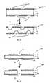
- a flow field plate 100 prepared for particulate etchingcomprises the plate material 3, and two opposite faces each layered with an adhesive 2 and 20 upon which the prepared particular enchant-resistant patterned masks 1 and 10 have been attached.
- the adhesive 2 and 20must provide sufficient adhesion to hold the masks 1 and 10 firmly in place during the particulate etching process 6.
- the adhesive 2 and 20is water soluble so that the masks 1 and 10 can be easily removed from the plate material 3 after etching.
- the masks 1 and 10may be mounted on a support film which is peeled away after the masks 1 and 10 have adhered to the adhesive 2 and 20.
- Plate material 3comprises carbon fibre composites, thereby possessing superior mechanical properties to monoliths, without loss of mechanical properties.
- the inclusion of carbon fibrescan improve the thermal conductivity of plate material 3, which is an important feature if the downstream electrical application involves use of high current densities.
- Fabrication methods for typical carbon-carbon composite materialare well known (See Thomas, C.R. [Editor], 1993, Essentials of carbon-carbon composites, Cambridge Royal Society of Chemistry Press, Cambridge, ISBN: 0851868045).
- the gas permeability of partially densified plate materialcan be overcome by densification with a polymeric filler such as resin.
- the resinshould preferably be of low viscosity to allow the rapid filling of small pores under low pressure, and should self-cure.
- the composition of the resinmay be of any polymer formulation that will resist attack by an alkaline or acidic electrolyte.
- unabsorbed resinshould be removed from the surface of the plate 100. This can be carried out by wiping the plate 100 surface with an absorbent cloth.
- the particulate etchant-resistant patterned masks 1 and 10have patterns 4 and 40 through which the plate material 3 will be etched. Pattern 4 on one face of plate material 3 is displaced relative to pattern 40 on the second face of plate material 3 so that a thin sheet of plate material 3 can be employed.
- Etching process 6involves the exposure of the plate 100 to a particulate etchant (not shown) which is propelled by a particulate etchant accelerator (not shown) such as a sandblasting gun.
- the particulate etchantis any material which has a greater hardness than that of the plate material 3 to be etched. For carbonaceous materials (except diamonds), it is preferred that fine grained silica or alumina is used.
- the etchant sizedepends on the detail of the patterns 4 and 40 required on the plate 100.
- the blasting pressure used in process 6is dependent on masks 1 and 10, the adhesive 2 and 20, the distance between the etchant accelerator and the target surface of the plate material 3, and the etchant used.
- An upper pressure limitis given by the resistance to erosive etching of the masks 1 and 10, while a lower limit is defined by the pressure required to erode the material 3 with the abrasive etchant.
- the blasting pressureis optimal when substantial etching is produced within a reasonable time limit without damaging the masks 1 and 10 or causing the adhesive 2 and 20 to fail.
- Etching process 6is performed in two successive steps in which each face of plate 100 is etched. It is not ruled out, however, that the etching process 6 could be performed on both sides of plate 100 simultaneously using a plurality of particulate etchant accelerators.
- the target area of plate 100is dependent on the spread of the etchant. This spread, in turn, is dependent on the distance of the particulate etchant accelerator from the surface of plate 100, and the dimensions of the particulate etchant accelerator nozzle (not shown).
- the plate 100can be etched in a dynamic manner if the area of plate 100 is larger than the etchant spread.
- the particulate etchant accelerator and plate 100can be moved relative to each other using a two-axis scanning mechanism, in which either or both the accelerator and plate 100 are moved. The overall movement should provide uniform coverage of the plate 100 surface with the accelerated etchant.
- the flow field plate 200After completion of etching process 6, the flow field plate 200 has a fluid flow field pattern 5 and 50 etched into the plate material 3 on both sides of the plate 200.
- the adhesive 2 and 20 and particulate etchant-resistant patterned mask 1 and 10are then removed.
- flow field plate 300requires the alignment of eroding grooves 7 and 70 patterned into the particulate etchant-resistant masks 1 and 10 on opposite faces of the plate material 3.
- the masks 1 and 10are held firmly against the plate material 3 using an adhesive 2 and 20.
- Etching process 60proceeds until a uniform opening 8 appears from one face of plate 400 through to the opposite face. Etching of both faces of plate material 3 to form the opening 8 is especially important where the material 3 would fail if etched from one face only.
- Example 1Carbon-carbon composite plate + vinyl mask
- a graphitised carbon-carbon composite plate of dimensions 50x50x1.2 mmwas prepared with a gas track design on one face.
- a vinyl-polymer adhesive mask(FasCal Film [Avery, US]), with a negative image of the required gas track design, was pressed firmly onto the composite.
- a Guyson Blast System(Guyson, UK) with 180-220 ⁇ m silica grit, was used to dry sandblasting the plate. The masked material was held under the sandblasting gun with a blast pressure set at 4 bar (400 kPa) for 30s, at a constant distance of 6" (152.4 mm). The vinyl mask was then peeled off, and the adhesive washed off the plate using isopropyl alcohol. Track depth was 0.2-0.25 mm.
- a graphitised carbon-carbon composite plate of dimensions 50x50x1.2 mmwas prepared with a gas track design on one face.
- a photoresist mask(ImagePro Super Film [Chromaline Corp., US]) was developed to form a negative template of the required gas track design.
- the filmwas exposed for 5 minutes to an 18 W UV light source, at a distance of 5 m.
- the filmwas then removed (under yellow light) and washed under running water for approximately 3 minutes in order to wash away unexposed resist.
- the resist filmwas dried in air, under normal lighting, to form the negative resist mask template.
- a liquid contact adhesive(ImagePro Adhesive [Chromaline Corp., US]) was brushed lightly over the composite plate surface, and allowed to dry in air for 10 minutes.
- the resist mask(with carrier film) was pressed onto the adhesive-covered plate, and the carrier film peeled away. The material was then blasted using the procedure described in Example 1 ( supra ). The resist mask was removed by dissolving the adhesive using warm running water, thus revealing a flow field pattern etched into the carbon-carbon composite material.
- Example 3Carbon-carbon composite plate with epoxy resin + photoresist mask
- a graphitised carbon-carbon composite plate of dimensions 50x50x1.2 mmwas held under low pressure (preferably less than 10 mmHg [approximately 1.33 kPa], but up to 100 mmHg [approximately 13.3 kPa] feasible) impregnated with a low viscosity epoxy resin (SpeciFix-20 [Struers Ltd, UK]). Excess resin was removed from the surface of the plate using a paper towel. The plate was then allowed to stand in air, at standard temperature and pressure, for at least 8 hours to allow the resin to cure and harden.
- a photoresist mask(ImagePro Super Film) was prepared and then applied as in Example 2 (supra). The masked material was then blasted using the procedure described in Example 1 ( supra ). The resist mask was removed by dissolving the adhesive using warm running water.
Landscapes
- Chemical & Material Sciences (AREA)
- Engineering & Computer Science (AREA)
- Life Sciences & Earth Sciences (AREA)
- Manufacturing & Machinery (AREA)
- Sustainable Development (AREA)
- Sustainable Energy (AREA)
- Chemical Kinetics & Catalysis (AREA)
- Electrochemistry (AREA)
- General Chemical & Material Sciences (AREA)
- Composite Materials (AREA)
- Mechanical Engineering (AREA)
- Paper (AREA)
- Non-Reversible Transmitting Devices (AREA)
- ing And Chemical Polishing (AREA)
- Pharmaceuticals Containing Other Organic And Inorganic Compounds (AREA)
- Fuel Cell (AREA)
- Inert Electrodes (AREA)
- Treatments For Attaching Organic Compounds To Fibrous Goods (AREA)
- Absorbent Articles And Supports Therefor (AREA)
- Transition And Organic Metals Composition Catalysts For Addition Polymerization (AREA)
- External Artificial Organs (AREA)
- Polishing Bodies And Polishing Tools (AREA)
- Treating Waste Gases (AREA)
- Glass Compositions (AREA)
- Physical Or Chemical Processes And Apparatus (AREA)
Abstract
Description
- Figure 1
- is a schematic side cross-sectional elevation illustrating theparticulate etching method employed in the fabrication offluid flow grooves on a bipolar flow field plate; and
- Figure 2
- is a schematic side cross-sectional elevation illustrating theparticulate etching method employed in the fabrication of afluid entry or exit hole in a flow field plate.
Claims (17)
- A method for the manufacture of flow field plates by sand blasting, beadblasting, or grit blasting, in which a particulate etchant-resistant patternedmask is used, so that a fluid flow pattern determined by the pattern design onsaid mask is formed on said plate material.
- A method according to claim 1, in which said plate material compriseselectrically conductive material.
- A method according to claim 1 or 2, in which said plate material comprisescarbon-based material.
- A method according to claim 3, in which said plate material comprises carbonfibre composite material.
- A method according to claim 4, in which said carbon fibre composite materialis densified with a polymeric filler.
- A method according to any one of claims 1 to 5, in which a sandblasting gunis used as a particulate etchant accelerator.
- A method according to any of claims 1 to 6, in which the sand, bead or gritmaterial has a greater hardness than that of said plate material.
- A method according to claim 7, in which the sand, bead or grit material issilica grit with a diameter of 180-220 µm.
- A method according to claim 8, in which said plate material is a graphitisedcarbon-carbon composite material.
- A method according to claim 1, in which said particulate etchant-resistantpatterned mask is held in contact with said plate material, by means of anadhesive substance.
- A method according to claim 1, in which said particulate etchant-resistantpatterned mask is a photoresist mask.
- A method according to claim 1, in which said particulate etchant-resistantpatterned mask comprises a vinyl polymer.
- A method according to claim 1, in which said pattern design determines afluid entry gallery and a fluid exit gallery on said flow field plate.
- A method according to claim 13, in which said fluid entry gallery and saidfluid exit gallery are formed by etching aligned positions on opposite faces ofsaid flow field plate such that said fluid entry gallery and said exit gallery passthrough said flow field plate.
- A method according to clam 1, in which said pattern design determines asealing groove on said flow field plate.
- A method according to claim 1, in which said sand, bead, or grit blasting isunder control of a two-axis scanning mechanism that determines movement ofa particulate etchant accelerator, for said sand beads or grit, relative to saidplate material.
- A method according to claim 16, in which said two-axis scanning mechanismenables a predetermined movement of said plate material relative to saidparticulate etchant accelerator such that said movement is in the form of araster pattern or a stepped scan pattern.
Applications Claiming Priority (3)
| Application Number | Priority Date | Filing Date | Title |
|---|---|---|---|
| GBGB9915925.3AGB9915925D0 (en) | 1999-07-08 | 1999-07-08 | Flow field plates |
| GB9915925 | 1999-07-08 | ||
| PCT/GB2000/002591WO2001004982A1 (en) | 1999-07-08 | 2000-07-04 | Flow field plates |
Publications (2)
| Publication Number | Publication Date |
|---|---|
| EP1196958A1 EP1196958A1 (en) | 2002-04-17 |
| EP1196958B1true EP1196958B1 (en) | 2003-04-02 |
Family
ID=10856830
Family Applications (1)
| Application Number | Title | Priority Date | Filing Date |
|---|---|---|---|
| EP00942284AExpired - LifetimeEP1196958B1 (en) | 1999-07-08 | 2000-07-04 | Flow field plates |
Country Status (16)
| Country | Link |
|---|---|
| US (1) | US20020071983A1 (en) |
| EP (1) | EP1196958B1 (en) |
| JP (1) | JP3561258B2 (en) |
| KR (1) | KR100449262B1 (en) |
| CN (1) | CN1197186C (en) |
| AT (1) | ATE236456T1 (en) |
| AU (1) | AU5698300A (en) |
| CA (1) | CA2378963A1 (en) |
| DE (1) | DE60001954T2 (en) |
| ES (1) | ES2195907T3 (en) |
| GB (2) | GB9915925D0 (en) |
| HK (1) | HK1073727B (en) |
| IS (1) | IS2005B (en) |
| MX (1) | MXPA02000159A (en) |
| NO (1) | NO328379B1 (en) |
| WO (1) | WO2001004982A1 (en) |
Families Citing this family (27)
| Publication number | Priority date | Publication date | Assignee | Title |
|---|---|---|---|---|
| US6322919B1 (en)* | 1999-08-16 | 2001-11-27 | Alliedsignal Inc. | Fuel cell and bipolar plate for use with same |
| KR100697253B1 (en)* | 2000-05-08 | 2007-03-21 | 혼다 기켄 고교 가부시키가이샤 | Fuel cell |
| JP4560181B2 (en)* | 2000-06-30 | 2010-10-13 | アイシン高丘株式会社 | Method and apparatus for manufacturing fuel cell separator |
| KR20020009828A (en)* | 2000-07-27 | 2002-02-02 | 윤종용 | Forming method of via-hole in ink-jet print head |
| WO2002065566A1 (en) | 2001-02-12 | 2002-08-22 | The Morgan Crucible Company Plc | Flow field plate geometries |
| GB2372143B (en)* | 2001-02-12 | 2003-04-09 | Morgan Crucible Co | Flow field plate geometries for a fuel cell, including for a polymer electrolyte fuel cell |
| GB2372144B (en)* | 2001-02-12 | 2003-02-12 | Morgan Crucible Co | Fuel cell stack incorporating integral flow field plates and gas diffusion layer |
| WO2002090053A1 (en)* | 2001-05-03 | 2002-11-14 | The Morgan Crucible Company Plc | Abrasive blast machining |
| GB2375501B (en)* | 2001-05-03 | 2003-07-09 | Morgan Crucible Co | Extrusion of graphitic bodies |
| GB2382455B (en) | 2001-11-07 | 2004-10-13 | Intelligent Energy Ltd | Fuel cell fluid flow field plates |
| KR20030042179A (en)* | 2001-11-21 | 2003-05-28 | 김준범 | Metal Structure Plate for Fuel Cell |
| DK1353394T3 (en)* | 2002-03-27 | 2005-08-01 | Haldor Topsoe As | Thin film solid oxide fuel cell (SOFC) and process for its preparation |
| GB2387476B (en)* | 2002-06-24 | 2004-03-17 | Morgan Crucible Co | Flow field plate geometries |
| US20040151960A1 (en)* | 2003-01-31 | 2004-08-05 | Rock Jeffrey Allan | Flow restrictors in fuel cell flow-field |
| DE10307278B4 (en)* | 2003-02-20 | 2008-03-27 | Staxera Gmbh | fuel cell stack |
| US6864004B2 (en)* | 2003-04-03 | 2005-03-08 | The Regents Of The University Of California | Direct methanol fuel cell stack |
| JP4367623B2 (en)* | 2004-01-14 | 2009-11-18 | 住友電気工業株式会社 | Method for producing electrical circuit component made of porous stretched polytetrafluoroethylene sheet or porous stretched polytetrafluoroethylene film, and electrical circuit component |
| JP2008511104A (en)* | 2004-08-19 | 2008-04-10 | ジーエム・グローバル・テクノロジー・オペレーションズ・インコーポレーテッド | Surface modification of fuel cell elements for improved water management |
| DE112006002142B4 (en)* | 2005-08-12 | 2021-02-11 | GM Global Technology Operations LLC (n. d. Ges. d. Staates Delaware) | Method of making a fuel cell component using an easily removable mask |
| DE102006010832A1 (en)* | 2006-03-07 | 2007-09-13 | Wilhelm Eisenhuth Gmbh Kg | Contact plate for low-temperature fuel cell, has inlet channels, outlet channels and flow field enclosed by groove, where cross section of channels is broader in flow direction, and side walls of channels obtain contour |
| CN100449836C (en)* | 2007-03-13 | 2009-01-07 | 北京科技大学 | A Hybrid Gradually Variable Flow Field Plate for Proton Exchange Membrane Fuel Cell |
| WO2009086023A2 (en)* | 2007-12-19 | 2009-07-09 | Applied Materials, Inc. | Methods for cleaning process kits and chambers, and for ruthenium recovery |
| CA3037825A1 (en)* | 2016-09-28 | 2018-04-05 | Sintokogio, Ltd. | Drilling method, resist layer, and fiber-reinforced plastic |
| US10581109B2 (en)* | 2017-03-30 | 2020-03-03 | International Business Machines Corporation | Fabrication method of all solid-state thin-film battery |
| US10944128B2 (en) | 2017-03-30 | 2021-03-09 | International Business Machines Corporation | Anode structure for solid-state lithium-based thin-film battery |
| US10903672B2 (en) | 2017-03-30 | 2021-01-26 | International Business Machines Corporation | Charge method for solid-state lithium-based thin-film battery |
| US10622680B2 (en) | 2017-04-06 | 2020-04-14 | International Business Machines Corporation | High charge rate, large capacity, solid-state battery |
Family Cites Families (84)
| Publication number | Priority date | Publication date | Assignee | Title |
|---|---|---|---|---|
| US2791289A (en)* | 1952-12-10 | 1957-05-07 | Simpson Timber Co | Process of forming fissured fiber acoustical tile and product thereof |
| US3270464A (en)* | 1964-04-28 | 1966-09-06 | Pangborn Corp | Abrasive blasting apparatus |
| FR1523248A (en)* | 1967-03-07 | 1968-05-03 | Thomson Houston Comp Francaise | Improvements in methods of manufacturing electrodes in the form of grids for electron tubes, electrodes manufactured using these improved methods and electron tubes containing such electrodes |
| US3840405A (en)* | 1970-04-08 | 1974-10-08 | Equipment Electr De Vehicles S | Circulating fuel cell with crenellated electrode |
| US4020535A (en)* | 1975-08-01 | 1977-05-03 | Metropolitan Circuits, Inc. | Method of making an electro-discharge electrode |
| GB1572049A (en)* | 1977-03-15 | 1980-07-23 | Data Recording Instr Co | Magnetic transducing heads |
| US4175165A (en)* | 1977-07-20 | 1979-11-20 | Engelhard Minerals & Chemicals Corporation | Fuel cell system utilizing ion exchange membranes and bipolar plates |
| FR2429490A1 (en)* | 1978-06-23 | 1980-01-18 | Thomson Csf | PYROLYTIC GRAPHITE GRID FOR HIGH POWER ELECTRONIC TUBE, AND MOUNTING METHOD THEREOF |
| US4169917A (en)* | 1978-07-10 | 1979-10-02 | Energy Research Corporation | Electrochemical cell and separator plate thereof |
| FR2437060A1 (en)* | 1978-09-19 | 1980-04-18 | Thomson Csf | PROCESS FOR MANUFACTURING PLANAR GRIDS IN PYROLYTIC GRAPHITE FOR ELECTRONIC TUBES |
| US4337571A (en)* | 1979-04-06 | 1982-07-06 | The United States Of America As Represented By The United States Department Of Energy | Method for producing a fuel cell manifold seal |
| US4212929A (en)* | 1979-04-06 | 1980-07-15 | The United States Of America As Represented By The United States Department Of Energy | Fuel cell manifold sealing system |
| US4339322A (en)* | 1980-04-21 | 1982-07-13 | General Electric Company | Carbon fiber reinforced fluorocarbon-graphite bipolar current collector-separator |
| US4301222A (en)* | 1980-08-25 | 1981-11-17 | United Technologies Corporation | Separator plate for electrochemical cells |
| US4407902A (en)* | 1980-12-08 | 1983-10-04 | Ford Motor Company | Chemically regenerable redox fuel cell and method of operating the same |
| US4396687A (en)* | 1980-12-08 | 1983-08-02 | Ford Motor Company | Chemically regenerable redox fuel cell and method of operating the same |
| US4390602A (en)* | 1981-09-21 | 1983-06-28 | Struthers Ralph C | Fuel cell |
| US4678724A (en)* | 1982-06-23 | 1987-07-07 | United Technologies Corporation | Fuel cell battery with improved membrane cooling |
| US4649091A (en)* | 1982-06-23 | 1987-03-10 | United Technologies Corporation | Fuel cell battery with improved membrane cooling |
| US4806080A (en)* | 1983-07-06 | 1989-02-21 | Ebara Corporation | Pump with shaftless impeller |
| JPS6014615A (en)* | 1983-07-06 | 1985-01-25 | Ebara Corp | Thrust bearing and it's manufacture |
| US4764449A (en)* | 1985-11-01 | 1988-08-16 | The Chromaline Corporation | Adherent sandblast photoresist laminate |
| US4714831A (en)* | 1986-05-01 | 1987-12-22 | International Business Machines | Spherical retarding grid analyzer |
| US4855193A (en)* | 1986-06-20 | 1989-08-08 | United Technologies Corporation | Bipolar fuel cell |
| US4702786A (en)* | 1986-10-01 | 1987-10-27 | Tallman Gary C | Sign sandblasting method |
| US4826741A (en)* | 1987-06-02 | 1989-05-02 | Ergenics Power Systems, Inc. | Ion exchange fuel cell assembly with improved water and thermal management |
| US4795683A (en)* | 1987-07-23 | 1989-01-03 | United Technologies Corporation | High power density evaporatively cooled ion exchange membrane fuel cell |
| US4769297A (en)* | 1987-11-16 | 1988-09-06 | International Fuel Cells Corporation | Solid polymer electrolyte fuel cell stack water management system |
| US4826742A (en)* | 1988-01-21 | 1989-05-02 | International Fuel Cells Corporation | Water and heat management in solid polymer fuel cell stack |
| US4824741A (en)* | 1988-02-12 | 1989-04-25 | International Fuel Cells Corporation | Solid polymer electrolyte fuel cell system with porous plate evaporative cooling |
| US4910099A (en)* | 1988-12-05 | 1990-03-20 | The United States Of America As Represented By The United States Department Of Energy | Preventing CO poisoning in fuel cells |
| US5342706A (en)* | 1989-05-03 | 1994-08-30 | Institute Of Gas Technology | Fully internal manifolded fuel cell stack |
| NL8901800A (en)* | 1989-07-12 | 1991-02-01 | Stichting Energie | SEPARATOR PLATE FOR APPLICATION IN A GAS FUEL CELL, INCLUDING A COLLECTION OF ELECTRODES, AND STACKING OF FUEL CELLS. |
| US4988583A (en)* | 1989-08-30 | 1991-01-29 | Her Majesty The Queen As Represented By The Minister Of National Defence Of Her Majesty's Canadian Government | Novel fuel cell fluid flow field plate |
| US5108849A (en)* | 1989-08-30 | 1992-04-28 | Her Majesty The Queen In Right Of Canada, As Represented By The Minister Of National Defence In Her Britannic Majesty's Government Of The United Kingdom Of Great Britain And Northern Ireland | Fuel cell fluid flow field plate |
| US5009968A (en)* | 1989-09-08 | 1991-04-23 | International Fuel Cells Corporation | Fuel cell end plate structure |
| US4985101A (en)* | 1989-09-18 | 1991-01-15 | Morrison Molded Fiber Glass Company | Method for the fabrication of sandblasted composite signs |
| US4973530A (en)* | 1989-12-21 | 1990-11-27 | The United States Of America As Represented By The United States Department Of Energy | Fuel cell water transport |
| US5064732A (en)* | 1990-02-09 | 1991-11-12 | International Fuel Cells Corporation | Solid polymer fuel cell system: high current density operation |
| US5069004A (en)* | 1990-02-27 | 1991-12-03 | Gillenwater R Lee | Abrasive engraving process |
| US5234776A (en)* | 1990-08-03 | 1993-08-10 | Fuji Electric Co., Ltd. | Solid polymer electrolyte fuel cell system with ribbed configuration |
| US5176966A (en)* | 1990-11-19 | 1993-01-05 | Ballard Power Systems Inc. | Fuel cell membrane electrode and seal assembly |
| US5366818A (en)* | 1991-01-15 | 1994-11-22 | Ballard Power Systems Inc. | Solid polymer fuel cell systems incorporating water removal at the anode |
| US5260143A (en)* | 1991-01-15 | 1993-11-09 | Ballard Power Systems Inc. | Method and apparatus for removing water from electrochemical fuel cells |
| EP0586461B1 (en)* | 1991-06-04 | 1995-09-13 | Ballard Power Systems Inc. | Gasketed membrane electrode assembly for electrochemical fuel cells |
| US5270127A (en)* | 1991-08-09 | 1993-12-14 | Ishikawajima-Harima Heavy Industries Co., Ltd. | Plate shift converter |
| US5252410A (en)* | 1991-09-13 | 1993-10-12 | Ballard Power Systems Inc. | Lightweight fuel cell membrane electrode assembly with integral reactant flow passages |
| US5230966A (en)* | 1991-09-26 | 1993-07-27 | Ballard Power Systems Inc. | Coolant flow field plate for electrochemical fuel cells |
| US5284718A (en)* | 1991-09-27 | 1994-02-08 | Ballard Power Systems Inc. | Fuel cell membrane electrode and seal assembly |
| US5242764A (en)* | 1991-12-17 | 1993-09-07 | Bcs Technology, Inc. | Near ambient, unhumidified solid polymer fuel cell |
| US5318863A (en)* | 1991-12-17 | 1994-06-07 | Bcs Technology, Inc. | Near ambient, unhumidified solid polymer fuel cell |
| US5262249A (en)* | 1991-12-26 | 1993-11-16 | International Fuel Cells Corporation | Internally cooled proton exchange membrane fuel cell device |
| US5264299A (en)* | 1991-12-26 | 1993-11-23 | International Fuel Cells Corporation | Proton exchange membrane fuel cell support plate and an assembly including the same |
| US5187025A (en)* | 1992-02-03 | 1993-02-16 | Analytic Power Corp. | Unitized fuel cell structure |
| JPH05253841A (en)* | 1992-03-05 | 1993-10-05 | Hitachi Ltd | Fine grain milling process device and its method |
| JP3245929B2 (en)* | 1992-03-09 | 2002-01-15 | 株式会社日立製作所 | Fuel cell and its application device |
| DE69325123T2 (en)* | 1992-03-23 | 1999-11-18 | Koninklijke Philips Electronics N.V., Eindhoven | Method of making a plate of an electrically insulating material with a pattern of holes or cavities for use in display devices |
| JP3352716B2 (en)* | 1992-03-31 | 2002-12-03 | 株式会社東芝 | Solid polymer electrolyte fuel cell device |
| US5350643A (en)* | 1992-06-02 | 1994-09-27 | Hitachi, Ltd. | Solid polymer electrolyte type fuel cell |
| JP3135991B2 (en)* | 1992-06-18 | 2001-02-19 | 本田技研工業株式会社 | Fuel cell and fuel cell stack tightening method |
| GB2268619B (en)* | 1992-07-01 | 1995-06-28 | Rolls Royce & Ass | A fuel cell |
| US5232792A (en)* | 1992-08-21 | 1993-08-03 | M-C Power Corporation | Cell separator plate used in fuel cell stacks |
| US5336570A (en)* | 1992-08-21 | 1994-08-09 | Dodge Jr Cleveland E | Hydrogen powered electricity generating planar member |
| GB2272430B (en)* | 1992-11-11 | 1995-12-20 | Vickers Shipbuilding & Eng | Processing of fuel gases,in particular for fuel cells and apparatus therefor |
| US5268239A (en)* | 1992-12-28 | 1993-12-07 | International Fuel Cells Corporation | Fluoropolymer laminated separator plate |
| US5460896A (en)* | 1993-01-22 | 1995-10-24 | Kabushiki Kaisha Equos Research | Fuel cell |
| JPH06255149A (en)* | 1993-03-08 | 1994-09-13 | Japan Servo Co Ltd | Thermal transfer color recorder |
| IT1270878B (en)* | 1993-04-30 | 1997-05-13 | Permelec Spa Nora | IMPROVED ELECTROCHEMISTRY CELL USING ION EXCHANGE MEMBRANES AND METAL BIPOLAR PLATES |
| JPH0729589A (en)* | 1993-07-09 | 1995-01-31 | Ishikawajima Harima Heavy Ind Co Ltd | Differential pressure control method for plate reformer in fuel cell power generator |
| US5360679A (en)* | 1993-08-20 | 1994-11-01 | Ballard Power Systems Inc. | Hydrocarbon fueled solid polymer fuel cell electric power generation system |
| BE1007714A3 (en)* | 1993-11-09 | 1995-10-03 | Philips Electronics Nv | Method for manufacturing a plate of electrical insulation materials with a pattern of holes and / or cavities. |
| US5527363A (en)* | 1993-12-10 | 1996-06-18 | Ballard Power Systems Inc. | Method of fabricating an embossed fluid flow field plate |
| BE1007894A3 (en)* | 1993-12-20 | 1995-11-14 | Philips Electronics Nv | Method for manufacturing a plate of non-metallic materials with a pattern of holes and / or cavities. |
| US5470671A (en)* | 1993-12-22 | 1995-11-28 | Ballard Power Systems Inc. | Electrochemical fuel cell employing ambient air as the oxidant and coolant |
| JPH0812303A (en)* | 1994-07-05 | 1996-01-16 | Ishikawajima Harima Heavy Ind Co Ltd | Plate reformer |
| US5484666A (en)* | 1994-09-20 | 1996-01-16 | Ballard Power Systems Inc. | Electrochemical fuel cell stack with compression mechanism extending through interior manifold headers |
| US5863671A (en)* | 1994-10-12 | 1999-01-26 | H Power Corporation | Plastic platelet fuel cells employing integrated fluid management |
| RU2174728C2 (en)* | 1994-10-12 | 2001-10-10 | Х Пауэр Корпорейшн | Fuel cell using integrated plate technology for liquid-distribution |
| FR2733856B1 (en)* | 1995-05-05 | 1997-08-29 | Thomson Tubes Electroniques | CATHODE FOR GRID ELECTRON CANON, GRID TO BE ASSOCIATED WITH SUCH A CATHODE AND ELECTRON CANON INCLUDING SUCH CATHODE |
| US5503944A (en)* | 1995-06-30 | 1996-04-02 | International Fuel Cells Corp. | Water management system for solid polymer electrolyte fuel cell power plants |
| US5514486A (en)* | 1995-09-01 | 1996-05-07 | The Regents Of The University Of California, Office Of Technology Transfer | Annular feed air breathing fuel cell stack |
| US5738574A (en)* | 1995-10-27 | 1998-04-14 | Applied Materials, Inc. | Continuous processing system for chemical mechanical polishing |
| US5686199A (en)* | 1996-05-07 | 1997-11-11 | Alliedsignal Inc. | Flow field plate for use in a proton exchange membrane fuel cell |
| US5798188A (en)* | 1997-06-25 | 1998-08-25 | E. I. Dupont De Nemours And Company | Polymer electrolyte membrane fuel cell with bipolar plate having molded polymer projections |
- 1999
- 1999-07-08GBGBGB9915925.3Apatent/GB9915925D0/ennot_activeCeased
- 2000
- 2000-07-04CNCNB008099251Apatent/CN1197186C/ennot_activeExpired - Fee Related
- 2000-07-04ATAT00942284Tpatent/ATE236456T1/ennot_activeIP Right Cessation
- 2000-07-04WOPCT/GB2000/002591patent/WO2001004982A1/enactiveIP Right Grant
- 2000-07-04ESES00942284Tpatent/ES2195907T3/ennot_activeExpired - Lifetime
- 2000-07-04JPJP2001509108Apatent/JP3561258B2/ennot_activeExpired - Fee Related
- 2000-07-04CACA002378963Apatent/CA2378963A1/ennot_activeAbandoned
- 2000-07-04HKHK02101692.7Apatent/HK1073727B/ennot_activeIP Right Cessation
- 2000-07-04MXMXPA02000159Apatent/MXPA02000159A/enactiveIP Right Grant
- 2000-07-04GBGB0112474Apatent/GB2359924B/ennot_activeExpired - Fee Related
- 2000-07-04AUAU56983/00Apatent/AU5698300A/ennot_activeAbandoned
- 2000-07-04KRKR10-2001-7016091Apatent/KR100449262B1/ennot_activeExpired - Fee Related
- 2000-07-04EPEP00942284Apatent/EP1196958B1/ennot_activeExpired - Lifetime
- 2000-07-04DEDE60001954Tpatent/DE60001954T2/ennot_activeExpired - Lifetime
- 2001
- 2001-06-06USUS09/875,685patent/US20020071983A1/ennot_activeAbandoned
- 2002
- 2002-01-07ISIS6221Apatent/IS2005B/enunknown
- 2002-01-07NONO20020065Apatent/NO328379B1/ennot_activeIP Right Cessation
Also Published As
| Publication number | Publication date |
|---|---|
| CA2378963A1 (en) | 2001-01-18 |
| ES2195907T3 (en) | 2003-12-16 |
| NO20020065L (en) | 2002-03-07 |
| GB2359924B (en) | 2001-12-19 |
| JP2003504823A (en) | 2003-02-04 |
| CN1197186C (en) | 2005-04-13 |
| WO2001004982A1 (en) | 2001-01-18 |
| MXPA02000159A (en) | 2003-07-21 |
| KR100449262B1 (en) | 2004-09-18 |
| US20020071983A1 (en) | 2002-06-13 |
| DE60001954T2 (en) | 2003-12-18 |
| IS2005B (en) | 2005-05-13 |
| IS6221A (en) | 2002-01-07 |
| KR20020062683A (en) | 2002-07-29 |
| NO20020065D0 (en) | 2002-01-07 |
| GB2359924A (en) | 2001-09-05 |
| GB9915925D0 (en) | 1999-09-08 |
| AU5698300A (en) | 2001-01-30 |
| EP1196958A1 (en) | 2002-04-17 |
| CN1359544A (en) | 2002-07-17 |
| NO328379B1 (en) | 2010-02-08 |
| DE60001954D1 (en) | 2003-05-08 |
| GB2359924A8 (en) | 2002-02-25 |
| HK1073727A1 (en) | 2005-10-14 |
| HK1073727B (en) | 2005-12-09 |
| GB0112474D0 (en) | 2001-07-11 |
| ATE236456T1 (en) | 2003-04-15 |
| JP3561258B2 (en) | 2004-09-02 |
Similar Documents
| Publication | Publication Date | Title |
|---|---|---|
| EP1196958B1 (en) | Flow field plates | |
| CA2390949C (en) | Systems, apparatus and methods for bonding and/or sealing electrochemical cell elements and assemblies | |
| KR100995480B1 (en) | Catalyst-coated ionomer membrane with protective film layer and membrane-electrode-assembly prepared therefrom | |
| CA2437892C (en) | Flow field plate geometries | |
| CA1273993A (en) | Electrode substrate for fuel cell | |
| GB2372143A (en) | Flow field plate geometries for a fuel cell,including for a polymer electrolyt e fuel cell | |
| CA2336647A1 (en) | Flexible graphite composite for use in the form of a fuel cell flow field plate | |
| CA2365337A1 (en) | Bipolar plates for fuel cell stacks | |
| US8105726B2 (en) | Fuel cell separator, method of manufacturing fuel cell separator, and fuel cell | |
| WO2000044055A3 (en) | Membrane-electrode assemblies for direct methanol fuel cells | |
| JP4759121B2 (en) | Manufacturing apparatus and manufacturing method of fuel cell separator | |
| AU2005200831A1 (en) | Flow field plates | |
| KR20110045769A (en) | Solid Gasket Formation Method of Fuel Cell Separator | |
| JP4410020B2 (en) | Method for producing separator material for fuel cell | |
| JP3930774B2 (en) | Manufacturing method of fuel cell | |
| CA2395413C (en) | Fuel cell separator and production method therefor | |
| KR100760312B1 (en) | Manufacturing method of metal separator plate for fuel cell | |
| CA2395422C (en) | Fuel cell separator | |
| CA2316630A1 (en) | Fuel cell separator production system and method, and fuel cell separator produced by same | |
| WO2002090052A1 (en) | Abrasive blast machining | |
| JP4181339B2 (en) | Assembling method of fuel cell | |
| GB2372144A (en) | Fuel cell stack incorporating integral flow field plates and gas diffusion layer | |
| CN111916785A (en) | Polar plate | |
| GB2375222A (en) | Flow field plates | |
| JP2005026137A (en) | Manufacturing method of fuel cell separator, fuel cell separator, and polymer electrolyte fuel cell |
Legal Events
| Date | Code | Title | Description |
|---|---|---|---|
| PUAI | Public reference made under article 153(3) epc to a published international application that has entered the european phase | Free format text:ORIGINAL CODE: 0009012 | |
| 17P | Request for examination filed | Effective date:20020129 | |
| AK | Designated contracting states | Kind code of ref document:A1 Designated state(s):AT BE CH CY DE DK ES FI FR GB GR IE IT LI LU MC NL | |
| AX | Request for extension of the european patent | Free format text:AL;LT;LV;MK;RO;SI | |
| 17Q | First examination report despatched | Effective date:20020618 | |
| GRAH | Despatch of communication of intention to grant a patent | Free format text:ORIGINAL CODE: EPIDOS IGRA | |
| GRAH | Despatch of communication of intention to grant a patent | Free format text:ORIGINAL CODE: EPIDOS IGRA | |
| GRAA | (expected) grant | Free format text:ORIGINAL CODE: 0009210 | |
| AK | Designated contracting states | Designated state(s):AT BE CH CY DE DK ES FI FR GB GR IE IT LI LU MC NL PT SE | |
| PG25 | Lapsed in a contracting state [announced via postgrant information from national office to epo] | Ref country code:FI Free format text:LAPSE BECAUSE OF FAILURE TO SUBMIT A TRANSLATION OF THE DESCRIPTION OR TO PAY THE FEE WITHIN THE PRESCRIBED TIME-LIMIT Effective date:20030402 Ref country code:LI Free format text:LAPSE BECAUSE OF FAILURE TO SUBMIT A TRANSLATION OF THE DESCRIPTION OR TO PAY THE FEE WITHIN THE PRESCRIBED TIME-LIMIT Effective date:20030402 Ref country code:CH Free format text:LAPSE BECAUSE OF FAILURE TO SUBMIT A TRANSLATION OF THE DESCRIPTION OR TO PAY THE FEE WITHIN THE PRESCRIBED TIME-LIMIT Effective date:20030402 Ref country code:AT Free format text:LAPSE BECAUSE OF FAILURE TO SUBMIT A TRANSLATION OF THE DESCRIPTION OR TO PAY THE FEE WITHIN THE PRESCRIBED TIME-LIMIT Effective date:20030402 | |
| REG | Reference to a national code | Ref country code:GB Ref legal event code:FG4D | |
| REG | Reference to a national code | Ref country code:CH Ref legal event code:EP | |
| REG | Reference to a national code | Ref country code:IE Ref legal event code:FG4D | |
| REF | Corresponds to: | Ref document number:60001954 Country of ref document:DE Date of ref document:20030508 Kind code of ref document:P | |
| PG25 | Lapsed in a contracting state [announced via postgrant information from national office to epo] | Ref country code:DK Free format text:LAPSE BECAUSE OF FAILURE TO SUBMIT A TRANSLATION OF THE DESCRIPTION OR TO PAY THE FEE WITHIN THE PRESCRIBED TIME-LIMIT Effective date:20030702 Ref country code:GR Free format text:LAPSE BECAUSE OF FAILURE TO SUBMIT A TRANSLATION OF THE DESCRIPTION OR TO PAY THE FEE WITHIN THE PRESCRIBED TIME-LIMIT Effective date:20030702 | |
| PG25 | Lapsed in a contracting state [announced via postgrant information from national office to epo] | Ref country code:LU Free format text:LAPSE BECAUSE OF NON-PAYMENT OF DUE FEES Effective date:20030704 Ref country code:IE Free format text:LAPSE BECAUSE OF NON-PAYMENT OF DUE FEES Effective date:20030704 Ref country code:PT Free format text:LAPSE BECAUSE OF FAILURE TO SUBMIT A TRANSLATION OF THE DESCRIPTION OR TO PAY THE FEE WITHIN THE PRESCRIBED TIME-LIMIT Effective date:20030704 Ref country code:CY Free format text:LAPSE BECAUSE OF FAILURE TO SUBMIT A TRANSLATION OF THE DESCRIPTION OR TO PAY THE FEE WITHIN THE PRESCRIBED TIME-LIMIT Effective date:20030704 | |
| REG | Reference to a national code | Ref country code:SE Ref legal event code:TRGR | |
| RAP2 | Party data changed (patent owner data changed or rights of a patent transferred) | Owner name:LOUGHBOROUGH UNIVERSITY ENTERPRISES LIMITED | |
| PG25 | Lapsed in a contracting state [announced via postgrant information from national office to epo] | Ref country code:MC Free format text:LAPSE BECAUSE OF NON-PAYMENT OF DUE FEES Effective date:20030731 | |
| LTIE | Lt: invalidation of european patent or patent extension | Effective date:20030402 | |
| NLT2 | Nl: modifications (of names), taken from the european patent patent bulletin | Owner name:LOUGHBOROUGH UNIVERSITY ENTERPRISES LIMITED | |
| REG | Reference to a national code | Ref country code:CH Ref legal event code:PL | |
| ET | Fr: translation filed | ||
| REG | Reference to a national code | Ref country code:ES Ref legal event code:FG2A Ref document number:2195907 Country of ref document:ES Kind code of ref document:T3 | |
| PLBE | No opposition filed within time limit | Free format text:ORIGINAL CODE: 0009261 | |
| STAA | Information on the status of an ep patent application or granted ep patent | Free format text:STATUS: NO OPPOSITION FILED WITHIN TIME LIMIT | |
| 26N | No opposition filed | Effective date:20040105 | |
| REG | Reference to a national code | Ref country code:IE Ref legal event code:MM4A | |
| PGFP | Annual fee paid to national office [announced via postgrant information from national office to epo] | Ref country code:NL Payment date:20070731 Year of fee payment:8 | |
| NLV4 | Nl: lapsed or anulled due to non-payment of the annual fee | Effective date:20090201 | |
| PG25 | Lapsed in a contracting state [announced via postgrant information from national office to epo] | Ref country code:NL Free format text:LAPSE BECAUSE OF NON-PAYMENT OF DUE FEES Effective date:20090201 | |
| PGFP | Annual fee paid to national office [announced via postgrant information from national office to epo] | Ref country code:FR Payment date:20100728 Year of fee payment:11 Ref country code:GB Payment date:20100618 Year of fee payment:11 Ref country code:IT Payment date:20100721 Year of fee payment:11 Ref country code:SE Payment date:20100719 Year of fee payment:11 | |
| PGFP | Annual fee paid to national office [announced via postgrant information from national office to epo] | Ref country code:DE Payment date:20100928 Year of fee payment:11 Ref country code:BE Payment date:20100803 Year of fee payment:11 | |
| PGFP | Annual fee paid to national office [announced via postgrant information from national office to epo] | Ref country code:ES Payment date:20110713 Year of fee payment:12 | |
| BERE | Be: lapsed | Owner name:LOUGHBOROUGH *UNIVERSITY INNOVATIONS LTD Effective date:20110731 | |
| REG | Reference to a national code | Ref country code:SE Ref legal event code:EUG | |
| GBPC | Gb: european patent ceased through non-payment of renewal fee | Effective date:20110704 | |
| REG | Reference to a national code | Ref country code:FR Ref legal event code:ST Effective date:20120330 | |
| PG25 | Lapsed in a contracting state [announced via postgrant information from national office to epo] | Ref country code:BE Free format text:LAPSE BECAUSE OF NON-PAYMENT OF DUE FEES Effective date:20110731 Ref country code:FR Free format text:LAPSE BECAUSE OF NON-PAYMENT OF DUE FEES Effective date:20110801 Ref country code:DE Free format text:LAPSE BECAUSE OF NON-PAYMENT OF DUE FEES Effective date:20120201 | |
| REG | Reference to a national code | Ref country code:DE Ref legal event code:R119 Ref document number:60001954 Country of ref document:DE Effective date:20120201 | |
| PG25 | Lapsed in a contracting state [announced via postgrant information from national office to epo] | Ref country code:IT Free format text:LAPSE BECAUSE OF NON-PAYMENT OF DUE FEES Effective date:20110704 | |
| PG25 | Lapsed in a contracting state [announced via postgrant information from national office to epo] | Ref country code:GB Free format text:LAPSE BECAUSE OF NON-PAYMENT OF DUE FEES Effective date:20110704 | |
| PG25 | Lapsed in a contracting state [announced via postgrant information from national office to epo] | Ref country code:SE Free format text:LAPSE BECAUSE OF NON-PAYMENT OF DUE FEES Effective date:20110705 | |
| REG | Reference to a national code | Ref country code:ES Ref legal event code:FD2A Effective date:20131021 | |
| PG25 | Lapsed in a contracting state [announced via postgrant information from national office to epo] | Ref country code:ES Free format text:LAPSE BECAUSE OF NON-PAYMENT OF DUE FEES Effective date:20120705 |