EP1196102B1 - Multiaxial connector for spinal implant - Google Patents
Multiaxial connector for spinal implantDownload PDFInfo
- Publication number
- EP1196102B1 EP1196102B1EP00946016AEP00946016AEP1196102B1EP 1196102 B1EP1196102 B1EP 1196102B1EP 00946016 AEP00946016 AEP 00946016AEP 00946016 AEP00946016 AEP 00946016AEP 1196102 B1EP1196102 B1EP 1196102B1
- Authority
- EP
- European Patent Office
- Prior art keywords
- bore
- connecting rod
- fixing screw
- connecting element
- connector according
- Prior art date
- Legal status (The legal status is an assumption and is not a legal conclusion. Google has not performed a legal analysis and makes no representation as to the accuracy of the status listed.)
- Expired - Lifetime
Links
- 239000007943implantSubstances0.000titleclaimsabstractdescription18
- 238000004873anchoringMethods0.000claimsdescription5
- 210000000988bone and boneAnatomy0.000claimsdescription5
- 230000003100immobilizing effectEffects0.000claims1
- 230000008878couplingEffects0.000description2
- 238000010168coupling processMethods0.000description2
- 238000005859coupling reactionMethods0.000description2
- 230000000717retained effectEffects0.000description2
- 230000000903blocking effectEffects0.000description1
- 210000001519tissueAnatomy0.000description1
Images


Classifications
- A—HUMAN NECESSITIES
- A61—MEDICAL OR VETERINARY SCIENCE; HYGIENE
- A61B—DIAGNOSIS; SURGERY; IDENTIFICATION
- A61B17/00—Surgical instruments, devices or methods
- A61B17/56—Surgical instruments or methods for treatment of bones or joints; Devices specially adapted therefor
- A61B17/58—Surgical instruments or methods for treatment of bones or joints; Devices specially adapted therefor for osteosynthesis, e.g. bone plates, screws or setting implements
- A61B17/68—Internal fixation devices, including fasteners and spinal fixators, even if a part thereof projects from the skin
- A61B17/70—Spinal positioners or stabilisers, e.g. stabilisers comprising fluid filler in an implant
- A61B17/7001—Screws or hooks combined with longitudinal elements which do not contact vertebrae
- A61B17/7035—Screws or hooks, wherein a rod-clamping part and a bone-anchoring part can pivot relative to each other
- A—HUMAN NECESSITIES
- A61—MEDICAL OR VETERINARY SCIENCE; HYGIENE
- A61B—DIAGNOSIS; SURGERY; IDENTIFICATION
- A61B17/00—Surgical instruments, devices or methods
- A61B17/56—Surgical instruments or methods for treatment of bones or joints; Devices specially adapted therefor
- A61B17/58—Surgical instruments or methods for treatment of bones or joints; Devices specially adapted therefor for osteosynthesis, e.g. bone plates, screws or setting implements
- A61B17/68—Internal fixation devices, including fasteners and spinal fixators, even if a part thereof projects from the skin
- A61B17/70—Spinal positioners or stabilisers, e.g. stabilisers comprising fluid filler in an implant
- A61B17/7001—Screws or hooks combined with longitudinal elements which do not contact vertebrae
- A61B17/7041—Screws or hooks combined with longitudinal elements which do not contact vertebrae with single longitudinal rod offset laterally from single row of screws or hooks
Definitions
- the present inventionrelates to a polyaxial connector for the constitution a spinal implant with connecting rods.
- the anchoring elementconsists of a fixing screw comprising a part anchor separated from a projecting threaded head, associated with a tightening nut, by an intermediate body of polygonal section forming a stop.
- the reception ringhas two branches joined by a connection zone to constitute a clip-forming element.
- the two branchesare pierced with opposite coaxial holes, intended to be traversed by the projecting threaded head of the fixing screw, and come to bear against the polygonal stop.
- connection zone of the two arms of the ringdelimits perpendicularly to the opposite holes a bore cooperating with a compressible sleeve provided a central passage provided for receiving the connecting rod.
- the assembly of the sleeve inside the bore of the ringis intended for create a ball joint to be able to position, before tightening the nut on the protruding threaded head of the fixing screw, the connecting rod in a position angular determined.
- the polyaxial connector according to the present inventioncomprises a first connection element which has on either side of the branch slit joined together by a curved wall, said branches being capable of deform under the tightening force of the nut of the fixing screw for locking in rotation of the connecting means.
- the polyaxial connector according to the present inventioncomprises a second connection element whose threaded hole opens into the next bore a perpendicular direction.
- the second threaded part 8is designed to receive a nut 9 for fixing to the screw 3 of the first connection element 4 which bears against the head intermediate 7.
- connection element 4has a slot 16 passing through the bore 10 and opening into the bore 13 at the level of the annular track 14.
- the element connection 4present on either side of the slot 16 of the branches 17, 18 joined together by a curved wall 19 delimiting the bore 13.
- the branches 17, 18are obviously each traversed by the bore 10 for the passage of the fixing screw 3.
- connection element 4makes it possible to give the connection element 4 a certain flexibility. so that it can deform under the tightening force of the nut 9 of the screw fixing 3, so that said connection element 4 constitutes a clamp allowing the angular blocking of the connecting means 15 integral with the element connection 5 as will be seen better below.
- connection element 5 of the polyaxial connector 1is pierced with a bore opening 20 intended to receive the connecting rod 2 of the spinal implant A.
- connection element 5is drilled perpendicular to the bore 20 of a hole threaded 21 which opens inside said bore and which is designed to receive a clamping screw 22 for locking in translation of the connecting rod 2 relative to to the connection element.
- connection element 5comprises connecting means 15 which are constituted on one of the external faces of said element of a finger 23 which is extended by a head 24 with a spherical profile.
- the first connection element 4is retained against a vertebra B of a patient by means of the fixing screw 3 which passes through the bore 10 provided for this purpose.
- the first connection element 4receives, before tightening the nut 9 on the second threaded part 8 of the fixing screw 3, the second connection element 5 by means of the connecting means 15 made up of the spherical head 24 which cooperates with the track with spherical profile 14 formed inside the bore 13 of said first connection element.
- the fixing means 15allow, on the one hand to couple the two together connection elements 4, 5 of the polyaxial connector 1, and on the other hand to produce between the two connection elements a ball joint connection for the angular adjustment of the connecting rod 2.
- the connecting means 15also allow the rod to be offset laterally. connection 2 with respect to the pivot center of the connection elements 4, 5 so that said rod can have a large angular movement.
- the connecting rod 2is introduced into the bore 20 of the connection element 5 and retained transversely inside of it by means of the screw clamp 22 which is screwed into the threaded hole 21.
Landscapes
- Health & Medical Sciences (AREA)
- Orthopedic Medicine & Surgery (AREA)
- Life Sciences & Earth Sciences (AREA)
- Neurology (AREA)
- Surgery (AREA)
- Heart & Thoracic Surgery (AREA)
- Engineering & Computer Science (AREA)
- Biomedical Technology (AREA)
- Nuclear Medicine, Radiotherapy & Molecular Imaging (AREA)
- Medical Informatics (AREA)
- Molecular Biology (AREA)
- Animal Behavior & Ethology (AREA)
- General Health & Medical Sciences (AREA)
- Public Health (AREA)
- Veterinary Medicine (AREA)
- Surgical Instruments (AREA)
- Prostheses (AREA)
Abstract
Description
Translated fromFrenchLa présente invention est relative à un connecteur polyaxial pour la constitutiond'un implant rachidien muni de tiges de liaison.The present invention relates to a polyaxial connector for the constitutiona spinal implant with connecting rods.
On connaít d'après le brevet français n° 2 731 344 un implant rachidienpermettant l'orientation angulaire d'une tige de liaison par rapport aux élémentsd'ancrage osseux.We know from French Patent No. 2,731,344 a spinal implantallowing the angular orientation of a connecting rod relative to the elementsbone anchor.
L'élément d'ancrage est constitué d'une vis de fixation comportant une partied'ancrage séparée d'une tête filetée saillante, associé à un écrou de serrage, parun corps intermédiaire de section polygonale formant butée.The anchoring element consists of a fixing screw comprising a partanchor separated from a projecting threaded head, associated with a tightening nut, byan intermediate body of polygonal section forming a stop.
L'élément d'ancrage comporte également une bague de réception qui coopèreavec la tête filetée saillante de la partie d'ancrage et qui permet la mise en placede la tige de liaison.The anchor also has a cooperating receiving ringwith the protruding threaded head of the anchoring part and which allows the establishmentof the connecting rod.
La bague de réception comporte deux branches réunies par une zone de liaisonpour constituer une élément formant pince. Les deux branches sont percées detrous coaxiaux en vis à vis, prévus pour être traversés par la tête filetée saillantede la vis de fixation, et venir en appui contre la butée polygonale.The reception ring has two branches joined by a connection zoneto constitute a clip-forming element. The two branches are pierced withopposite coaxial holes, intended to be traversed by the projecting threaded headof the fixing screw, and come to bear against the polygonal stop.
La zone de liaison des deux branches de la bague délimite perpendiculairementaux trous en vis à vis un alésage coopérant avec une douille compressible munid'un passage central prévu pour recevoir la tige de liaison.The connection zone of the two arms of the ring delimits perpendicularlyto the opposite holes a bore cooperating with a compressible sleeve provideda central passage provided for receiving the connecting rod.
L'assemblage de la douille à l'intérieur de l'alésage de la bague est destiné àcréer une liaison rotule pour pouvoir positionner, avant le serrage de l'écrou sur latête filetée saillante de la vis de fixation, la tige de liaison dans une positionangulaire déterminée.The assembly of the sleeve inside the bore of the ring is intended forcreate a ball joint to be able to position, before tightening the nut on theprotruding threaded head of the fixing screw, the connecting rod in a positionangular determined.
L'implant rachidien décrit ci-dessus comporte certains inconvénients en ce quiconcerne le montage de la douille à l'intérieur de l'alésage de la bague formant laliaison rotule pour le pivotement de la tige de liaison. En effet, on remarque quecet assemblage ne permet pas un débattement suffisant de la tige de liaison lorsdu montage de l'implant rachidien, car ladite tige vient buter contre les bordsextérieurs supérieur et inférieur de l'alésage.The spinal implant described above has certain disadvantages in thatconcerns the fitting of the sleeve inside the bore of the ring forming theball joint for pivoting the connecting rod. Indeed, we notice thatthis assembly does not allow sufficient travel of the connecting rod duringmounting the spinal implant, because said rod abuts against the edgesupper and lower exterior of the bore.
C'est à ces inconvénients qu'entend plus particulièrement remédier la présenteinvention.It is to these drawbacks that the present present intends more particularly to remedy.invention.
En effet le connecteur polyaxial pour implant rachidien suivant la présenteinvention à pour objet d'une part de pouvoir pivoter dans toutes les directions parrapport aux corps vertébraux et d'autre part de permettre un pivotement degrande amplitude de la tige de liaison par rapport audit connecteur.Indeed the polyaxial connector for spinal implant according to the presentinvention aims on the one hand to be able to pivot in all directions byrelation to the vertebral bodies and secondly to allow a pivoting oflarge amplitude of the connecting rod relative to said connector.
Le connecteur polyaxial suivant la présente invention comprend :
- une tige de liaison, une vis de fixation comportant une première partie filetéepour son ancrage dans le tissu osseux, une tête intermédiaire à profilhexagonal et une seconde partie filetée recevant un écrou de serrage ;
- un premier élément de connexion percé d'un premier alésage prévu pourrecevoir la seconde partie filetée de la vis de fixation, d'un second alésagecomportant dans sa partie interne une piste annulaire à profil sphérique etd'une fente traversant le premier alésage pour venir déboucher à l'intérieur dusecond alésage au niveau de la piste annulaire ;
- un second élément de connexion percé d'un alésage prévu pour recevoir la tigede liaison, d'un trou fileté coopérant avec une vis de serrage pour le blocage entranslation de ladite tige ;
- et un dispositif de liaison formant rotule qui permet, d'une part l'accouplementdes premier et second éléments de connexion entre eux, de manière quelesdits éléments puissent pivoter l'un par rapport à l'autre pour présenter la tigede liaison dans une position angulaire déterminée, et d'autre part de décalerlatéralement la tige de liaison par rapport au centre de pivotement desditséléments.
- a connecting rod, a fixing screw comprising a first threaded part for its anchoring in the bone tissue, an intermediate head with a hexagonal profile and a second threaded part receiving a tightening nut;
- a first connection element pierced with a first bore intended to receive the second threaded part of the fixing screw, a second bore comprising in its internal part an annular track with a spherical profile and a slot passing through the first bore for come into the interior of the second bore at the level of the annular track;
- a second connection element pierced with a bore provided for receiving the connecting rod, with a threaded hole cooperating with a clamping screw for locking in translation of said rod;
- and a ball joint connecting device which allows, on the one hand the coupling of the first and second connecting elements to each other, so that said elements can pivot relative to each other to present the connecting rod in a determined angular position, and secondly to laterally offset the connecting rod relative to the pivot center of said elements.
Le connecteur polyaxial suivant la présente invention comporte un secondélément de connexion pourvu du dispositif de liaison qui est constitué sur l'unedes faces extérieures dudit élément d'un doigt qui se prolonge par une tête à profilsphérique de sorte que ladite tête puisse coopérer avec la piste annulaire à profilsphérique du second alésage du premier élément de connexion.The polyaxial connector according to the present invention comprises a secondconnection element provided with the connection device which is formed on oneexternal faces of said element of a finger which is extended by a profile headspherical so that said head can cooperate with the annular profile trackspherical of the second bore of the first connection element.
Le connecteur polyaxial suivant la présente invention comprend un premierélément dont le premier alésage comporte des portées cylindrique sur lesquellesviennent prendre appui respectivement l'écrou de serrage et la tête intermédiairede la vis de fixation lors du blocage en rotation du dispositif de liaison par leserrage dudit écrou.The polyaxial connector according to the present invention comprises a firstelement whose first bore has cylindrical bearing surfaces on whichcome to bear respectively the clamping nut and the intermediate headof the fixing screw when the connection device is blocked in rotation by thetightening said nut.
Le connecteur polyaxial suivant la présente invention comprend un premierélément de connexion qui présente de part et d'autre de la fente des branchesréunies entre elles par une paroi courbe, lesdites branches étant susceptibles de se déformer sous l'effort de serrage de l'écrou de la vis de fixation pour le blocageen rotation des moyens de liaison.The polyaxial connector according to the present invention comprises a firstconnection element which has on either side of the branch slitjoined together by a curved wall, said branches being capable ofdeform under the tightening force of the nut of the fixing screw for lockingin rotation of the connecting means.
Le connecteur polyaxial suivant la présente invention comprend un premierélément de connexion dont la fente est disposée dans un plan qui coupeperpendiculairement les axes principaux des alésages.The polyaxial connector according to the present invention comprises a firstconnection element the slot of which is arranged in a plane which cutsperpendicularly to the main axes of the bores.
Le connecteur polyaxial suivant la présente invention comprend un secondélément de connexion dont le trou fileté débouche à l'intérieur de l'alésage suivantune direction perpendiculaire.The polyaxial connector according to the present invention comprises a secondconnection element whose threaded hole opens into the next borea perpendicular direction.
La description qui va suivre en regard des dessins annexés, donnés à titred'exemple non limitatif, permettra de mieux comprendre l'invention, lescaractéristiques qu'elle présente et les avantages qu'elle est susceptible deprocurer :
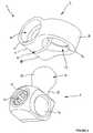
On a montré en figures 1 à 3 un connecteur polyaxial 1 permettant avec d'autresconnecteurs de même genre la fixation d'une tige de liaison 2 pour la réalisationd'un implant rachidien A. Chaque connecteur polyaxial 1 de l'implant rachidien Aest fixé sur le corps d'une vertèbre B d'une colonne vertébrale.We have shown in Figures 1 to 3 a
Ainsi, chaque connecteur polyaxial 1 de l'implant rachidien A comporte une vis defixation 3, des premier et second éléments de connexion 4, 5 permettant laréception de la tige de liaison 2 et des moyens ou dispositif de liaison 15 formantrotule pour l'accouplement et le pivotement des éléments 4, 5 entre eux.Thus, each
La vis de fixation 3 comporte une première partie filetée 6 pour son ancrage dansle tissu osseux d'une vertèbre B, une tête intermédiaire 7 à profil hexagonalformant butée, et une seconde partie filetée 8 s'étendant dans le prolongement etau-dessus de ladite butée.The
La tête intermédiaire 7 permet l'entraínement en rotation de la vis de fixation 3pour que la partie filetée 6 pénètre dans le tissu osseux de la vertèbre Bcorrespondante.The intermediate head 7 allows the rotation of the
La seconde partie filetée 8 est prévue pour recevoir un écrou 9 pour la fixation surla vis 3 du premier élément de connexion 4 qui vient en appui contre la têteintermédiaire 7.The second threaded
Le premier élément de connexion 4 est percé d'un alésage débouchant 10comportant des portées cylindriques 11, 12 sur lesquelles viennent prendre appuirespectivement l'écrou de serrage 9 et la tête intermédiaire 7 de la vis de fixation3 lorsque celle-ci vient traverser l'alésage 10.The
L'élément de connexion 4 est percé perpendiculairement à l'alésage 10 d'un autrealésage débouchant 13 qui comporte dans sa partie interne et en son milieu unepiste annulaire 14 dont le profil est en portion de sphère.The
L'élément de connexion 4 comporte une fente 16 traversant l'alésage 10 etdébouchant dans l'alésage 13 au niveau de la piste annulaire 14. Ainsi, l'élémentde connexion 4 présente de part et d'autre de la fente 16 des branches 17, 18réunies entre elles par une paroi courbe 19 délimitant l'alésage 13. Les branches17, 18 sont bien évidemment traversées chacune par l'alésage 10 pour lepassage de la vis de fixation 3.The
La fente 16 est disposée dans un plan qui coupe perpendiculairement les axesprincipaux des alésages débouchant 10 et 13.The
La fente 16 permet de donner à l'élément de connexion 4 une certaine souplessepour que celui-ci puisse se déformer sous l'effort de serrage de l'écrou 9 de la visde fixation 3, afin que ledit élément de connexion 4 constitue une pincepermettant le blocage angulaire des moyens de liaison 15 solidaire de l'élémentde connexion 5 comme on le verra mieux plus loin.The
L'élément de connexion 5 du connecteur polyaxial 1 est percé d'un alésagedébouchant 20 destiné à recevoir la tige de liaison 2 de l'implant rachidien A.The
L'élément de connexion 5 est percé perpendiculairement à l'alésage 20 d'un troufileté 21 qui débouche à l'intérieur dudit alésage et qui est prévu pour recevoir unevis de serrage 22 pour le blocage en translation de la tige de liaison 2 par rapportà l'élément de connexion.The
L'élément de connexion 5 comporte des moyens de liaison 15 qui sont constituéssur l'une des faces extérieures dudit élément d'un doigt 23 qui se prolonge parune tête 24 à profil sphérique.The
Le premier élément de connexion 4 est retenu contre une vertèbre B d'un patientpar l'intermédiaire de la vis de fixation 3 qui traverse l'alésage 10 prévu à cet effet.The
Le premier élément de connexion 4 reçoit, avant le serrage de l'écrou 9 sur laseconde partie filetée 8 de la vis de fixation 3, le second élément de connexion 5par l'intermédiaire des moyens de liaison 15 constitués de la tête sphérique 24 quicoopère avec la piste à profil sphérique 14 ménagée à l'intérieur de l'alésage 13dudit premier élément de connexion.The
Les moyens de fixation 15 permettent, d'une part d'accoupler ensemble les deuxéléments de connexion 4, 5 du connecteur polyaxial 1, et d'autre part de réaliser entre les deux éléments de connexion une liaison rotule pour le réglage angulairede la tige de liaison 2.The fixing means 15 allow, on the one hand to couple the two together
Les moyens de liaison 15 permettent également de décaler latéralement la tige deliaison 2 par rapport au centre de pivotement des éléments de connexion 4, 5 afinque ladite tige puissent présenter un débattement angulaire important.The connecting means 15 also allow the rod to be offset laterally.
La tige de liaison 2 est introduite dans l'alésage 20 de l'élément de connexion 5 etretenue transversalement à l'intérieur de celui-ci par l'intermédiaire de la vis deserrage 22 qui est vissée dans le trou fileté 21.The connecting
Lorsque la position angulaire de la tige de liaison 2 est déterminée par la rotationde la tête sphérique 24 à l'intérieur de la piste sphérique 14 de l'alésage 13,l'écrou 9 est serré sur la tête filetée 8 de la vis de fixation 3 de manière à déformerle premier élément de connexion 4 au moyen de la fente 16 afin de bloquer la têtesphérique 24 à l'intérieur de la piste 14.When the angular position of the connecting
Lors du blocage des moyens de liaison 15, on remarque que la butée 7 et l'écrou9 de la vis de fixation 3 viennent respectivement en appui contre la portée 11 et12 de l'alésage 10.When the
On note lors du serrage de l'écrou 9 de la vis de fixation 3 que les éléments deconnexions 4 et 5 ne viennent pas en contact avec l'articulation de la vertèbre Bcorrespondante du fait de position de la butée 7 sur ladite vis.It is noted when tightening the
Claims (6)
- Multiaxis connector for producing a spinal implant(A) to keep a connecting rod (2) in determinedangular positions with respect to the vertebralbodies (B), said connector (1) comprising bores,one of which is intended to receive the connectingrod (2), and a second of which is intended tocooperate with a fixing screw (3) comprising afirst threaded part (6) for anchoring it into thebone tissue, an intermediate head (7) of hexagonalprofile and a second threaded part (8) that takesa clamping nut (9),characterized in that eachmultiaxis connector (1) comprises:a fixing screw (3) consisting of a firstthreaded part (6), an intermediate head (7)with a hexagonal profile forming a stop, anda second threaded part (8) receiving aclamping nut (9);a first connecting element (4) pierced with afirst bore (10) designed to receive thesecond threaded part (8) of the fixing screw(3), with a second bore (13), comprising, inits interior part, an annular track (14) ofspherical profile, and with a slot (16)passing through the first bore (10) to openinto the second bore (13) at the annulartrack (14);a second connecting element (5) pierced witha bore (20) designed to receive theconnecting rod (2), with a threaded hole (21)collaborating with a binding screw (22) forimmobilizing said rod in terms oftranslation;and a connecting device (15) forming a balljoint which, on the one hand, allows thefirst and second connecting elements (4, 5)to be coupled to one another in such a waythat said elements can pivot one with respectto the other so as to present the connectingrod (2) in determined angular positions and,on the other hand, allow the connecting rod(2) to be offset laterally with respect tothe centre of pivoting of said elements (4,5).
- Multiaxis connector according to Claim 1,characterized in that the second connectingelement (5) comprises a connecting device (15)which consists, on one of the exterior faces ofsaid element, of a finger (23) extended by a head(24) with a spherical profile so that said headcan collaborate with the annular track (14) ofspherical profile of the second bore (13) of thefirst connecting element (4).
- Multiaxis connector according to Claim 1,characterized in that the first bore (10)comprises cylindrical bearing surfaces (11, 12) onwhich the clamping nut (9) and the intermediatehead (7) of the fixing screw (3) respectively bearwhen the connecting device (15) is immobilized interms of rotation by the tightening of said nut(9).
- Multiaxis connector according to Claim 1,characterized in that the first connecting element(4) has, on each side of the slot (16), branches(17, 18) joined together by a curved wall (19),said branches being able to deform under theclamping force of the nut (9) of the fixing screw(3) to immobilize the connecting device (15) interms of rotation.
- Multiaxis connector according to Claim 1,characterized in that the slot (16) is arranged ina plane which intersects the main axes of thebores (10, 13) of the first connecting element (4)at right angles.
- Multiaxis connector according to Claim 1,characterized in that the second connectingelement (5) comprises a threaded hole (21) whichopens into the bore (20) in a perpendiculardirection.
Applications Claiming Priority (3)
| Application Number | Priority Date | Filing Date | Title |
|---|---|---|---|
| FR9909755 | 1999-07-23 | ||
| FR9909755AFR2796546B1 (en) | 1999-07-23 | 1999-07-23 | POLYAXIAL CONNECTOR FOR SPINAL IMPLANT |
| PCT/FR2000/001781WO2001006939A1 (en) | 1999-07-23 | 2000-06-26 | Multiaxial connector for spinal implant |
Publications (2)
| Publication Number | Publication Date |
|---|---|
| EP1196102A1 EP1196102A1 (en) | 2002-04-17 |
| EP1196102B1true EP1196102B1 (en) | 2004-09-01 |
Family
ID=9548590
Family Applications (1)
| Application Number | Title | Priority Date | Filing Date |
|---|---|---|---|
| EP00946016AExpired - LifetimeEP1196102B1 (en) | 1999-07-23 | 2000-06-26 | Multiaxial connector for spinal implant |
Country Status (11)
| Country | Link |
|---|---|
| US (1) | US6676661B1 (en) |
| EP (1) | EP1196102B1 (en) |
| JP (1) | JP4587628B2 (en) |
| KR (1) | KR100592837B1 (en) |
| AT (1) | ATE274852T1 (en) |
| AU (1) | AU5991900A (en) |
| DE (1) | DE60013449T2 (en) |
| ES (1) | ES2225176T3 (en) |
| FR (1) | FR2796546B1 (en) |
| HU (1) | HU224419B1 (en) |
| WO (1) | WO2001006939A1 (en) |
Cited By (6)
| Publication number | Priority date | Publication date | Assignee | Title |
|---|---|---|---|---|
| US8585741B2 (en) | 2007-07-19 | 2013-11-19 | DePuy Synthes Products, LLC | Clamps used for interconnecting a bone anchor to a rod |
| US9808281B2 (en) | 2009-05-20 | 2017-11-07 | DePuy Synthes Products, Inc. | Patient-mounted retraction |
| US10098666B2 (en) | 2011-05-27 | 2018-10-16 | DePuy Synthes Products, Inc. | Minimally invasive spinal fixation system including vertebral alignment features |
| US10441325B2 (en) | 2006-04-11 | 2019-10-15 | DePuy Synthes Products, Inc. | Minimally invasive fixation system |
| US10888360B2 (en) | 2010-04-23 | 2021-01-12 | DePuy Synthes Products, Inc. | Minimally invasive instrument set, devices, and related methods |
| US12440248B2 (en) | 2022-06-28 | 2025-10-14 | DePuy Synthes Products, Inc. | Minimally invasive instrument set, devices, and related methods |
Families Citing this family (221)
| Publication number | Priority date | Publication date | Assignee | Title |
|---|---|---|---|---|
| US7674293B2 (en) | 2004-04-22 | 2010-03-09 | Facet Solutions, Inc. | Crossbar spinal prosthesis having a modular design and related implantation methods |
| ATE285207T1 (en) | 1999-10-22 | 2005-01-15 | Archus Orthopedics Inc | FACET ARTHROPLASTY DEVICES |
| US7691145B2 (en) | 1999-10-22 | 2010-04-06 | Facet Solutions, Inc. | Prostheses, systems and methods for replacement of natural facet joints with artificial facet joint surfaces |
| US8187303B2 (en) | 2004-04-22 | 2012-05-29 | Gmedelaware 2 Llc | Anti-rotation fixation element for spinal prostheses |
| FR2801778B1 (en)* | 1999-12-03 | 2002-02-08 | Spinevision | CONNECTION ASSEMBLY FOR THE FIELD OF RACHIDIAN OSTEOSYNTHESIS |
| AU2001280476B2 (en)* | 2000-06-30 | 2005-11-24 | Stephen Ritland | Polyaxial connection device and method |
| US7833250B2 (en) | 2004-11-10 | 2010-11-16 | Jackson Roger P | Polyaxial bone screw with helically wound capture connection |
| US7837716B2 (en)* | 2000-08-23 | 2010-11-23 | Jackson Roger P | Threadform for medical implant closure |
| US20060083603A1 (en)* | 2000-08-23 | 2006-04-20 | Jackson Roger P | Reverse angled threadform with anti-splay clearance |
| US20060025771A1 (en)* | 2000-08-23 | 2006-02-02 | Jackson Roger P | Helical reverse angle guide and advancement structure with break-off extensions |
| US6520962B1 (en)* | 2000-10-23 | 2003-02-18 | Sdgi Holdings, Inc. | Taper-locked adjustable connector |
| US8377100B2 (en)* | 2000-12-08 | 2013-02-19 | Roger P. Jackson | Closure for open-headed medical implant |
| US6726689B2 (en)* | 2002-09-06 | 2004-04-27 | Roger P. Jackson | Helical interlocking mating guide and advancement structure |
| US8353932B2 (en) | 2005-09-30 | 2013-01-15 | Jackson Roger P | Polyaxial bone anchor assembly with one-piece closure, pressure insert and plastic elongate member |
| US7862587B2 (en) | 2004-02-27 | 2011-01-04 | Jackson Roger P | Dynamic stabilization assemblies, tool set and method |
| US10729469B2 (en) | 2006-01-09 | 2020-08-04 | Roger P. Jackson | Flexible spinal stabilization assembly with spacer having off-axis core member |
| US10258382B2 (en) | 2007-01-18 | 2019-04-16 | Roger P. Jackson | Rod-cord dynamic connection assemblies with slidable bone anchor attachment members along the cord |
| US8292926B2 (en) | 2005-09-30 | 2012-10-23 | Jackson Roger P | Dynamic stabilization connecting member with elastic core and outer sleeve |
| DE10136162B4 (en)* | 2001-07-25 | 2016-05-12 | Biedermann Technologies Gmbh & Co. Kg | Connecting element for connecting two used for bone and spine stabilization rod-shaped elements |
| US6673074B2 (en)* | 2001-08-02 | 2004-01-06 | Endius Incorporated | Apparatus for retaining bone portions in a desired spatial relationship |
| DE60238997D1 (en) | 2001-09-28 | 2011-03-03 | Stephen Ritland | CHROME OR HOOKS |
| FR2831420B1 (en)* | 2001-10-30 | 2004-07-16 | Vitatech | APPARATUS FOR HOLDING THE SPIN WITH JOINTING ASSEMBLY |
| ATE476930T1 (en) | 2002-02-20 | 2010-08-15 | Stephen Ritland | DEVICE FOR CONNECTING HAND SCREWS |
| US6966910B2 (en)* | 2002-04-05 | 2005-11-22 | Stephen Ritland | Dynamic fixation device and method of use |
| ATE552789T1 (en)* | 2002-05-08 | 2012-04-15 | Stephen Ritland | DYNAMIC FIXATION DEVICE |
| FR2842093B1 (en)* | 2002-07-12 | 2005-04-15 | Scient X | BONE ANCHORING DEVICE WITH SPHERICAL JOINT |
| US20060009773A1 (en)* | 2002-09-06 | 2006-01-12 | Jackson Roger P | Helical interlocking mating guide and advancement structure |
| US8282673B2 (en)* | 2002-09-06 | 2012-10-09 | Jackson Roger P | Anti-splay medical implant closure with multi-surface removal aperture |
| US8876868B2 (en)* | 2002-09-06 | 2014-11-04 | Roger P. Jackson | Helical guide and advancement flange with radially loaded lip |
| WO2006052796A2 (en) | 2004-11-10 | 2006-05-18 | Jackson Roger P | Helical guide and advancement flange with break-off extensions |
| US8257402B2 (en)* | 2002-09-06 | 2012-09-04 | Jackson Roger P | Closure for rod receiving orthopedic implant having left handed thread removal |
| EP1596738A4 (en)* | 2003-02-25 | 2010-01-20 | Stephen Ritland | Adjustable rod and connector device and method of use |
| US6716214B1 (en) | 2003-06-18 | 2004-04-06 | Roger P. Jackson | Polyaxial bone screw with spline capture connection |
| US7621918B2 (en) | 2004-11-23 | 2009-11-24 | Jackson Roger P | Spinal fixation tool set and method |
| US8540753B2 (en) | 2003-04-09 | 2013-09-24 | Roger P. Jackson | Polyaxial bone screw with uploaded threaded shank and method of assembly and use |
| US20040230304A1 (en) | 2003-05-14 | 2004-11-18 | Archus Orthopedics Inc. | Prostheses, tools and methods for replacement of natural facet joints with artifical facet joint surfaces |
| US7608104B2 (en) | 2003-05-14 | 2009-10-27 | Archus Orthopedics, Inc. | Prostheses, tools and methods for replacement of natural facet joints with artifical facet joint surfaces |
| US7377923B2 (en) | 2003-05-22 | 2008-05-27 | Alphatec Spine, Inc. | Variable angle spinal screw assembly |
| WO2004110247A2 (en)* | 2003-05-22 | 2004-12-23 | Stephen Ritland | Intermuscular guide for retractor insertion and method of use |
| FR2856270B1 (en)* | 2003-06-17 | 2006-02-10 | Eurosurgical | PEDICULAR HOOKS FOR SPINAL INK DEVICE. |
| US8926670B2 (en) | 2003-06-18 | 2015-01-06 | Roger P. Jackson | Polyaxial bone screw assembly |
| US8366753B2 (en)* | 2003-06-18 | 2013-02-05 | Jackson Roger P | Polyaxial bone screw assembly with fixed retaining structure |
| US8092500B2 (en)* | 2007-05-01 | 2012-01-10 | Jackson Roger P | Dynamic stabilization connecting member with floating core, compression spacer and over-mold |
| US8257398B2 (en)* | 2003-06-18 | 2012-09-04 | Jackson Roger P | Polyaxial bone screw with cam capture |
| US7967850B2 (en) | 2003-06-18 | 2011-06-28 | Jackson Roger P | Polyaxial bone anchor with helical capture connection, insert and dual locking assembly |
| US8137386B2 (en) | 2003-08-28 | 2012-03-20 | Jackson Roger P | Polyaxial bone screw apparatus |
| US7776067B2 (en) | 2005-05-27 | 2010-08-17 | Jackson Roger P | Polyaxial bone screw with shank articulation pressure insert and method |
| US7766915B2 (en)* | 2004-02-27 | 2010-08-03 | Jackson Roger P | Dynamic fixation assemblies with inner core and outer coil-like member |
| US8398682B2 (en)* | 2003-06-18 | 2013-03-19 | Roger P. Jackson | Polyaxial bone screw assembly |
| US8377102B2 (en) | 2003-06-18 | 2013-02-19 | Roger P. Jackson | Polyaxial bone anchor with spline capture connection and lower pressure insert |
| US20100211114A1 (en)* | 2003-06-18 | 2010-08-19 | Jackson Roger P | Polyaxial bone anchor with shelf capture connection |
| US7074238B2 (en) | 2003-07-08 | 2006-07-11 | Archus Orthopedics, Inc. | Prostheses, tools and methods for replacement of natural facet joints with artificial facet joint surfaces |
| US20050021040A1 (en)* | 2003-07-21 | 2005-01-27 | Rudolf Bertagnoli | Vertebral retainer-distracter and method of using same |
| US7083622B2 (en)* | 2003-11-10 | 2006-08-01 | Simonson Peter M | Artificial facet joint and method |
| US7708764B2 (en)* | 2003-11-10 | 2010-05-04 | Simonson Peter M | Method for creating an artificial facet |
| US7862586B2 (en) | 2003-11-25 | 2011-01-04 | Life Spine, Inc. | Spinal stabilization systems |
| US20050131406A1 (en) | 2003-12-15 | 2005-06-16 | Archus Orthopedics, Inc. | Polyaxial adjustment of facet joint prostheses |
| US7179261B2 (en) | 2003-12-16 | 2007-02-20 | Depuy Spine, Inc. | Percutaneous access devices and bone anchor assemblies |
| US7527638B2 (en) | 2003-12-16 | 2009-05-05 | Depuy Spine, Inc. | Methods and devices for minimally invasive spinal fixation element placement |
| US11419642B2 (en) | 2003-12-16 | 2022-08-23 | Medos International Sarl | Percutaneous access devices and bone anchor assemblies |
| US7678137B2 (en)* | 2004-01-13 | 2010-03-16 | Life Spine, Inc. | Pedicle screw constructs for spine fixation systems |
| JP2007525274A (en) | 2004-02-27 | 2007-09-06 | ロジャー・ピー・ジャクソン | Orthopedic implant rod reduction instrument set and method |
| US11241261B2 (en) | 2005-09-30 | 2022-02-08 | Roger P Jackson | Apparatus and method for soft spinal stabilization using a tensionable cord and releasable end structure |
| US7160300B2 (en) | 2004-02-27 | 2007-01-09 | Jackson Roger P | Orthopedic implant rod reduction tool set and method |
| US8152810B2 (en) | 2004-11-23 | 2012-04-10 | Jackson Roger P | Spinal fixation tool set and method |
| US8236028B2 (en) | 2004-03-31 | 2012-08-07 | Depuy Spine Sarl | Spinal rod connector |
| US7406775B2 (en) | 2004-04-22 | 2008-08-05 | Archus Orthopedics, Inc. | Implantable orthopedic device component selection instrument and methods |
| US7051451B2 (en) | 2004-04-22 | 2006-05-30 | Archus Orthopedics, Inc. | Facet joint prosthesis measurement and implant tools |
| WO2006055186A2 (en) | 2004-10-25 | 2006-05-26 | Archus Orthopedics, Inc. | Spinal prosthesis having a modular design |
| US7914556B2 (en) | 2005-03-02 | 2011-03-29 | Gmedelaware 2 Llc | Arthroplasty revision system and method |
| US7572282B2 (en) | 2004-04-23 | 2009-08-11 | Depuy Spine Sarl | Spinal fixation plates and plate extensions |
| US8021398B2 (en)* | 2004-06-09 | 2011-09-20 | Life Spine, Inc. | Spinal fixation system |
| US7744635B2 (en)* | 2004-06-09 | 2010-06-29 | Spinal Generations, Llc | Spinal fixation system |
| US7938848B2 (en)* | 2004-06-09 | 2011-05-10 | Life Spine, Inc. | Spinal fixation system |
| US7744634B2 (en)* | 2004-06-15 | 2010-06-29 | Warsaw Orthopedic, Inc. | Spinal rod system |
| US8079823B2 (en)* | 2004-07-21 | 2011-12-20 | Delta T Corporation | Fan blades |
| AU2005277363A1 (en) | 2004-08-18 | 2006-03-02 | Fsi Acquisition Sub, Llc | Adjacent level facet arthroplasty devices, spine stabilization systems, and methods |
| US7455639B2 (en)* | 2004-09-20 | 2008-11-25 | Stephen Ritland | Opposing parallel bladed retractor and method of use |
| US7651502B2 (en) | 2004-09-24 | 2010-01-26 | Jackson Roger P | Spinal fixation tool set and method for rod reduction and fastener insertion |
| US8226690B2 (en) | 2005-07-22 | 2012-07-24 | The Board Of Trustees Of The Leland Stanford Junior University | Systems and methods for stabilization of bone structures |
| US20070225713A1 (en)* | 2004-10-20 | 2007-09-27 | Moti Altarac | Systems and methods for posterior dynamic stabilization of the spine |
| US8267969B2 (en) | 2004-10-20 | 2012-09-18 | Exactech, Inc. | Screw systems and methods for use in stabilization of bone structures |
| US20060095037A1 (en)* | 2004-10-29 | 2006-05-04 | Jones Bryan S | Connector assemblies for connecting a bone anchor to a fixation element |
| US8926672B2 (en) | 2004-11-10 | 2015-01-06 | Roger P. Jackson | Splay control closure for open bone anchor |
| US9168069B2 (en) | 2009-06-15 | 2015-10-27 | Roger P. Jackson | Polyaxial bone anchor with pop-on shank and winged insert with lower skirt for engaging a friction fit retainer |
| US8444681B2 (en) | 2009-06-15 | 2013-05-21 | Roger P. Jackson | Polyaxial bone anchor with pop-on shank, friction fit retainer and winged insert |
| US9980753B2 (en) | 2009-06-15 | 2018-05-29 | Roger P Jackson | pivotal anchor with snap-in-place insert having rotation blocking extensions |
| US8308782B2 (en) | 2004-11-23 | 2012-11-13 | Jackson Roger P | Bone anchors with longitudinal connecting member engaging inserts and closures for fixation and optional angulation |
| US7875065B2 (en)* | 2004-11-23 | 2011-01-25 | Jackson Roger P | Polyaxial bone screw with multi-part shank retainer and pressure insert |
| US9216041B2 (en) | 2009-06-15 | 2015-12-22 | Roger P. Jackson | Spinal connecting members with tensioned cords and rigid sleeves for engaging compression inserts |
| WO2006057837A1 (en) | 2004-11-23 | 2006-06-01 | Jackson Roger P | Spinal fixation tool attachment structure |
| WO2006058221A2 (en) | 2004-11-24 | 2006-06-01 | Abdou Samy M | Devices and methods for inter-vertebral orthopedic device placement |
| US7896905B2 (en)* | 2005-02-09 | 2011-03-01 | David Lee | Bone fixation apparatus |
| US7901437B2 (en) | 2007-01-26 | 2011-03-08 | Jackson Roger P | Dynamic stabilization member with molded connection |
| US10076361B2 (en) | 2005-02-22 | 2018-09-18 | Roger P. Jackson | Polyaxial bone screw with spherical capture, compression and alignment and retention structures |
| US8496686B2 (en) | 2005-03-22 | 2013-07-30 | Gmedelaware 2 Llc | Minimally invasive spine restoration systems, devices, methods and kits |
| WO2007011431A2 (en)* | 2005-07-18 | 2007-01-25 | Dong Myung Jeon | Bi-polar bone screw assembly |
| JP4988735B2 (en) | 2005-07-19 | 2012-08-01 | リットランド、ステファン | Rod extension for elongating fusion structures |
| US8523865B2 (en) | 2005-07-22 | 2013-09-03 | Exactech, Inc. | Tissue splitter |
| US7628799B2 (en) | 2005-08-23 | 2009-12-08 | Aesculap Ag & Co. Kg | Rod to rod connector |
| DE502006002049D1 (en) | 2005-09-13 | 2008-12-24 | Bird Biedermann Ag | Dynamic clamping device for spinal implant |
| WO2007040553A1 (en)* | 2005-09-26 | 2007-04-12 | Dong Jeon | Hybrid jointed bone screw system |
| US8105368B2 (en)* | 2005-09-30 | 2012-01-31 | Jackson Roger P | Dynamic stabilization connecting member with slitted core and outer sleeve |
| US7704271B2 (en)* | 2005-12-19 | 2010-04-27 | Abdou M Samy | Devices and methods for inter-vertebral orthopedic device placement |
| US20080294198A1 (en)* | 2006-01-09 | 2008-11-27 | Jackson Roger P | Dynamic spinal stabilization assembly with torsion and shear control |
| EP1971282A2 (en)* | 2006-01-10 | 2008-09-24 | Life Spine, Inc. | Pedicle screw constructs and spinal rod attachment assemblies |
| US8029545B2 (en)* | 2006-02-07 | 2011-10-04 | Warsaw Orthopedic Inc. | Articulating connecting member and anchor systems for spinal stabilization |
| US7699874B2 (en)* | 2006-03-01 | 2010-04-20 | Warsaw Orthopedic, Inc. | Low profile spinal rod connector system |
| WO2007114834A1 (en)* | 2006-04-05 | 2007-10-11 | Dong Myung Jeon | Multi-axial, double locking bone screw assembly |
| DE602006009069D1 (en)* | 2006-04-06 | 2009-10-22 | Biedermann Motech Gmbh | Angled polyaxial bone anchoring device |
| US7867255B2 (en)* | 2006-04-07 | 2011-01-11 | Warsaw Orthopedic, Inc. | Spinal rod connector system and method for a bone anchor |
| EP2308402A3 (en)* | 2006-05-15 | 2011-04-27 | Biomet Spain Orthopaedics S.L. | Surgical screw system |
| US7959564B2 (en) | 2006-07-08 | 2011-06-14 | Stephen Ritland | Pedicle seeker and retractor, and methods of use |
| US8388660B1 (en) | 2006-08-01 | 2013-03-05 | Samy Abdou | Devices and methods for superior fixation of orthopedic devices onto the vertebral column |
| US8702755B2 (en) | 2006-08-11 | 2014-04-22 | Gmedelaware 2 Llc | Angled washer polyaxial connection for dynamic spine prosthesis |
| US20080147122A1 (en)* | 2006-10-12 | 2008-06-19 | Jackson Roger P | Dynamic stabilization connecting member with molded inner segment and surrounding external elastomer |
| US8096996B2 (en) | 2007-03-20 | 2012-01-17 | Exactech, Inc. | Rod reducer |
| CA2670988C (en) | 2006-12-08 | 2014-03-25 | Roger P. Jackson | Tool system for dynamic spinal implants |
| US8366745B2 (en) | 2007-05-01 | 2013-02-05 | Jackson Roger P | Dynamic stabilization assembly having pre-compressed spacers with differential displacements |
| US8475498B2 (en) | 2007-01-18 | 2013-07-02 | Roger P. Jackson | Dynamic stabilization connecting member with cord connection |
| US10792074B2 (en) | 2007-01-22 | 2020-10-06 | Roger P. Jackson | Pivotal bone anchor assemly with twist-in-place friction fit insert |
| KR100991204B1 (en)* | 2007-01-23 | 2010-11-01 | 주식회사 바이오스마트 | Spinos process for spine spacer |
| WO2008094572A2 (en)* | 2007-01-30 | 2008-08-07 | Dong Myung Jeon | Anterior cervical plating system |
| US8372121B2 (en)* | 2007-02-08 | 2013-02-12 | Warsaw Orthopedic, Inc. | Adjustable coupling systems for spinal stabilization members |
| US8012177B2 (en)* | 2007-02-12 | 2011-09-06 | Jackson Roger P | Dynamic stabilization assembly with frusto-conical connection |
| US8979904B2 (en) | 2007-05-01 | 2015-03-17 | Roger P Jackson | Connecting member with tensioned cord, low profile rigid sleeve and spacer with torsion control |
| US10383660B2 (en) | 2007-05-01 | 2019-08-20 | Roger P. Jackson | Soft stabilization assemblies with pretensioned cords |
| US7947065B2 (en) | 2008-11-14 | 2011-05-24 | Ortho Innovations, Llc | Locking polyaxial ball and socket fastener |
| US7942909B2 (en) | 2009-08-13 | 2011-05-17 | Ortho Innovations, Llc | Thread-thru polyaxial pedicle screw system |
| US8197518B2 (en) | 2007-05-16 | 2012-06-12 | Ortho Innovations, Llc | Thread-thru polyaxial pedicle screw system |
| US7951173B2 (en)* | 2007-05-16 | 2011-05-31 | Ortho Innovations, Llc | Pedicle screw implant system |
| US7942910B2 (en) | 2007-05-16 | 2011-05-17 | Ortho Innovations, Llc | Polyaxial bone screw |
| US7942911B2 (en) | 2007-05-16 | 2011-05-17 | Ortho Innovations, Llc | Polyaxial bone screw |
| CA2690038C (en)* | 2007-05-31 | 2012-11-27 | Roger P. Jackson | Dynamic stabilization connecting member with pre-tensioned solid core |
| US8048115B2 (en)* | 2007-06-05 | 2011-11-01 | Spartek Medical, Inc. | Surgical tool and method for implantation of a dynamic bone anchor |
| US8083772B2 (en)* | 2007-06-05 | 2011-12-27 | Spartek Medical, Inc. | Dynamic spinal rod assembly and method for dynamic stabilization of the spine |
| US8048123B2 (en)* | 2007-06-05 | 2011-11-01 | Spartek Medical, Inc. | Spine implant with a deflection rod system and connecting linkages and method |
| US8021396B2 (en) | 2007-06-05 | 2011-09-20 | Spartek Medical, Inc. | Configurable dynamic spinal rod and method for dynamic stabilization of the spine |
| US8114134B2 (en) | 2007-06-05 | 2012-02-14 | Spartek Medical, Inc. | Spinal prosthesis having a three bar linkage for motion preservation and dynamic stabilization of the spine |
| US8092501B2 (en)* | 2007-06-05 | 2012-01-10 | Spartek Medical, Inc. | Dynamic spinal rod and method for dynamic stabilization of the spine |
| US8048128B2 (en)* | 2007-06-05 | 2011-11-01 | Spartek Medical, Inc. | Revision system and method for a dynamic stabilization and motion preservation spinal implantation system and method |
| US20090105764A1 (en)* | 2007-10-23 | 2009-04-23 | Jackson Roger P | Dynamic stabilization member with fin support and solid core extension |
| US8911477B2 (en)* | 2007-10-23 | 2014-12-16 | Roger P. Jackson | Dynamic stabilization member with end plate support and cable core extension |
| US20090171395A1 (en)* | 2007-12-28 | 2009-07-02 | Jeon Dong M | Dynamic spinal rod system |
| US20090192548A1 (en)* | 2008-01-25 | 2009-07-30 | Jeon Dong M | Pedicle-laminar dynamic spinal stabilization device |
| US20090194206A1 (en)* | 2008-01-31 | 2009-08-06 | Jeon Dong M | Systems and methods for wrought nickel/titanium alloy flexible spinal rods |
| US8267979B2 (en)* | 2008-02-26 | 2012-09-18 | Spartek Medical, Inc. | Load-sharing bone anchor having a deflectable post and axial spring and method for dynamic stabilization of the spine |
| US8333792B2 (en)* | 2008-02-26 | 2012-12-18 | Spartek Medical, Inc. | Load-sharing bone anchor having a deflectable post and method for dynamic stabilization of the spine |
| US8057517B2 (en) | 2008-02-26 | 2011-11-15 | Spartek Medical, Inc. | Load-sharing component having a deflectable post and centering spring and method for dynamic stabilization of the spine |
| US8211155B2 (en)* | 2008-02-26 | 2012-07-03 | Spartek Medical, Inc. | Load-sharing bone anchor having a durable compliant member and method for dynamic stabilization of the spine |
| US8048125B2 (en)* | 2008-02-26 | 2011-11-01 | Spartek Medical, Inc. | Versatile offset polyaxial connector and method for dynamic stabilization of the spine |
| US8337536B2 (en) | 2008-02-26 | 2012-12-25 | Spartek Medical, Inc. | Load-sharing bone anchor having a deflectable post with a compliant ring and method for stabilization of the spine |
| US8007518B2 (en)* | 2008-02-26 | 2011-08-30 | Spartek Medical, Inc. | Load-sharing component having a deflectable post and method for dynamic stabilization of the spine |
| US8097024B2 (en) | 2008-02-26 | 2012-01-17 | Spartek Medical, Inc. | Load-sharing bone anchor having a deflectable post and method for stabilization of the spine |
| US8083775B2 (en)* | 2008-02-26 | 2011-12-27 | Spartek Medical, Inc. | Load-sharing bone anchor having a natural center of rotation and method for dynamic stabilization of the spine |
| US20100036437A1 (en)* | 2008-02-26 | 2010-02-11 | Spartek Medical, Inc. | Load-sharing bone anchor having a deflectable post with a compliant ring and method for stabilization of the spine |
| WO2009124196A2 (en)* | 2008-04-03 | 2009-10-08 | Life Spine, Inc. | Top loading polyaxial spine screw assembly with one step lockup |
| AU2010260521C1 (en) | 2008-08-01 | 2013-08-01 | Roger P. Jackson | Longitudinal connecting member with sleeved tensioned cords |
| US11241257B2 (en)* | 2008-10-13 | 2022-02-08 | Nuvasive Specialized Orthopedics, Inc. | Spinal distraction system |
| US20090143823A1 (en)* | 2008-11-13 | 2009-06-04 | Jeon Dong M | Transverse connector system for spinal rods |
| US8075603B2 (en) | 2008-11-14 | 2011-12-13 | Ortho Innovations, Llc | Locking polyaxial ball and socket fastener |
| US9492214B2 (en) | 2008-12-18 | 2016-11-15 | Michel H. Malek | Flexible spinal stabilization system |
| US20100262190A1 (en)* | 2009-04-09 | 2010-10-14 | Warsaw Orthopedic, Inc. | Spinal rod translation device |
| CN103826560A (en) | 2009-06-15 | 2014-05-28 | 罗杰.P.杰克逊 | Polyaxial Bone Anchor with Socket Stem and Winged Inserts with Friction Fit Compression Collars |
| US9668771B2 (en) | 2009-06-15 | 2017-06-06 | Roger P Jackson | Soft stabilization assemblies with off-set connector |
| US11229457B2 (en) | 2009-06-15 | 2022-01-25 | Roger P. Jackson | Pivotal bone anchor assembly with insert tool deployment |
| US8998959B2 (en) | 2009-06-15 | 2015-04-07 | Roger P Jackson | Polyaxial bone anchors with pop-on shank, fully constrained friction fit retainer and lock and release insert |
| US8876867B2 (en) | 2009-06-24 | 2014-11-04 | Zimmer Spine, Inc. | Spinal correction tensioning system |
| EP2279706B1 (en)* | 2009-07-28 | 2011-09-28 | Biedermann Motech GmbH | Bone anchoring device |
| EP2485654B1 (en)* | 2009-10-05 | 2021-05-05 | Jackson P. Roger | Polyaxial bone anchor with non-pivotable retainer and pop-on shank, some with friction fit |
| US20110118783A1 (en)* | 2009-11-16 | 2011-05-19 | Spartek Medical, Inc. | Load-sharing bone anchor having a flexible post and method for dynamic stabilization of the spine |
| CN102695465A (en) | 2009-12-02 | 2012-09-26 | 斯帕泰克医疗股份有限公司 | Low profile spinal prosthesis incorporating a bone anchor having a deflectable post and a compound spinal rod |
| US8764806B2 (en) | 2009-12-07 | 2014-07-01 | Samy Abdou | Devices and methods for minimally invasive spinal stabilization and instrumentation |
| US12383311B2 (en) | 2010-05-14 | 2025-08-12 | Roger P. Jackson | Pivotal bone anchor assembly and method for use thereof |
| US20110307015A1 (en) | 2010-06-10 | 2011-12-15 | Spartek Medical, Inc. | Adaptive spinal rod and methods for stabilization of the spine |
| WO2012030712A1 (en) | 2010-08-30 | 2012-03-08 | Zimmer Spine, Inc. | Polyaxial pedicle screw |
| AU2011299558A1 (en) | 2010-09-08 | 2013-05-02 | Roger P. Jackson | Dynamic stabilization members with elastic and inelastic sections |
| US9301787B2 (en) | 2010-09-27 | 2016-04-05 | Mmsn Limited Partnership | Medical apparatus and method for spinal surgery |
| AU2011324058A1 (en) | 2010-11-02 | 2013-06-20 | Roger P. Jackson | Polyaxial bone anchor with pop-on shank and pivotable retainer |
| US8591551B2 (en)* | 2011-01-14 | 2013-11-26 | Warsaw Orthopedic, Inc. | Linked spinal stabilization elements for spinal fixation |
| JP5865479B2 (en) | 2011-03-24 | 2016-02-17 | ロジャー・ピー・ジャクソン | Multiaxial bone anchor with compound joint and pop-mounted shank |
| US9005249B2 (en) | 2011-07-11 | 2015-04-14 | Life Spine, Inc. | Spinal rod connector assembly |
| US8845728B1 (en) | 2011-09-23 | 2014-09-30 | Samy Abdou | Spinal fixation devices and methods of use |
| US8911479B2 (en) | 2012-01-10 | 2014-12-16 | Roger P. Jackson | Multi-start closures for open implants |
| US8430916B1 (en) | 2012-02-07 | 2013-04-30 | Spartek Medical, Inc. | Spinal rod connectors, methods of use, and spinal prosthesis incorporating spinal rod connectors |
| US20130226240A1 (en) | 2012-02-22 | 2013-08-29 | Samy Abdou | Spinous process fixation devices and methods of use |
| US9198767B2 (en) | 2012-08-28 | 2015-12-01 | Samy Abdou | Devices and methods for spinal stabilization and instrumentation |
| US9320617B2 (en) | 2012-10-22 | 2016-04-26 | Cogent Spine, LLC | Devices and methods for spinal stabilization and instrumentation |
| US9023087B2 (en)* | 2012-11-09 | 2015-05-05 | Blackstone Medical, Inc. | Percutaneous modular head-to-head cross connector |
| US8911478B2 (en) | 2012-11-21 | 2014-12-16 | Roger P. Jackson | Splay control closure for open bone anchor |
| US10058354B2 (en) | 2013-01-28 | 2018-08-28 | Roger P. Jackson | Pivotal bone anchor assembly with frictional shank head seating surfaces |
| US8852239B2 (en) | 2013-02-15 | 2014-10-07 | Roger P Jackson | Sagittal angle screw with integral shank and receiver |
| US9743959B2 (en)* | 2013-03-14 | 2017-08-29 | Atlas Spine, Inc. | Low profile spinal fixation system |
| US9453526B2 (en) | 2013-04-30 | 2016-09-27 | Degen Medical, Inc. | Bottom-loading anchor assembly |
| WO2015023420A2 (en) | 2013-07-25 | 2015-02-19 | Latitude Holdings, Llc | Percutaneous pedicle screw revision system |
| US9566092B2 (en) | 2013-10-29 | 2017-02-14 | Roger P. Jackson | Cervical bone anchor with collet retainer and outer locking sleeve |
| US9717533B2 (en) | 2013-12-12 | 2017-08-01 | Roger P. Jackson | Bone anchor closure pivot-splay control flange form guide and advancement structure |
| US9451993B2 (en) | 2014-01-09 | 2016-09-27 | Roger P. Jackson | Bi-radial pop-on cervical bone anchor |
| US9597119B2 (en) | 2014-06-04 | 2017-03-21 | Roger P. Jackson | Polyaxial bone anchor with polymer sleeve |
| US10064658B2 (en) | 2014-06-04 | 2018-09-04 | Roger P. Jackson | Polyaxial bone anchor with insert guides |
| US10070895B2 (en) | 2015-09-30 | 2018-09-11 | Amendia, Inc. | Dual tulip assembly |
| US10857003B1 (en) | 2015-10-14 | 2020-12-08 | Samy Abdou | Devices and methods for vertebral stabilization |
| US9603634B1 (en) | 2015-11-13 | 2017-03-28 | Amendia, Inc. | Percutaneous rod-to-rod cross connector |
| US10321939B2 (en) | 2016-05-18 | 2019-06-18 | Medos International Sarl | Implant connectors and related methods |
| US10517647B2 (en) | 2016-05-18 | 2019-12-31 | Medos International Sarl | Implant connectors and related methods |
| US10973648B1 (en) | 2016-10-25 | 2021-04-13 | Samy Abdou | Devices and methods for vertebral bone realignment |
| US10744000B1 (en) | 2016-10-25 | 2020-08-18 | Samy Abdou | Devices and methods for vertebral bone realignment |
| US10398476B2 (en) | 2016-12-13 | 2019-09-03 | Medos International Sàrl | Implant adapters and related methods |
| US10492835B2 (en) | 2016-12-19 | 2019-12-03 | Medos International Sàrl | Offset rods, offset rod connectors, and related methods |
| US10238432B2 (en) | 2017-02-10 | 2019-03-26 | Medos International Sàrl | Tandem rod connectors and related methods |
| US10966761B2 (en) | 2017-03-28 | 2021-04-06 | Medos International Sarl | Articulating implant connectors and related methods |
| US10561454B2 (en) | 2017-03-28 | 2020-02-18 | Medos International Sarl | Articulating implant connectors and related methods |
| ES2712653B2 (en)* | 2017-11-14 | 2020-07-27 | Benlloch Juan Antonio Martin | Sacrum prosthesis |
| US11076890B2 (en) | 2017-12-01 | 2021-08-03 | Medos International Sàrl | Rod-to-rod connectors having robust rod closure mechanisms and related methods |
| US10966762B2 (en) | 2017-12-15 | 2021-04-06 | Medos International Sarl | Unilateral implant holders and related methods |
| US11179248B2 (en) | 2018-10-02 | 2021-11-23 | Samy Abdou | Devices and methods for spinal implantation |
| USD1004774S1 (en) | 2019-03-21 | 2023-11-14 | Medos International Sarl | Kerrison rod reducer |
| US11291481B2 (en) | 2019-03-21 | 2022-04-05 | Medos International Sarl | Rod reducers and related methods |
| US11291482B2 (en) | 2019-03-21 | 2022-04-05 | Medos International Sarl | Rod reducers and related methods |
| EP4240262B1 (en) | 2020-11-09 | 2024-12-04 | Medos International Sàrl | Biplanar forceps reducers |
| US20240041502A1 (en)* | 2020-12-14 | 2024-02-08 | Johannes Hendrik Davis | Spinal rod coupler and system for spinal corrective surgery |
Family Cites Families (12)
| Publication number | Priority date | Publication date | Assignee | Title |
|---|---|---|---|---|
| US5129900B1 (en)* | 1990-07-24 | 1998-12-29 | Acromed Corp | Spinal column retaining method and apparatus |
| FR2676911B1 (en)* | 1991-05-30 | 1998-03-06 | Psi Ste Civile Particuliere | INTERVERTEBRAL STABILIZATION DEVICE WITH SHOCK ABSORBERS. |
| JP3308271B2 (en)* | 1992-06-25 | 2002-07-29 | ジンテーズ アクチエンゲゼルシャフト,クール | Osteosynthesis fixation device |
| US6176861B1 (en)* | 1994-10-25 | 2001-01-23 | Sdgi Holdings, Inc. | Modular spinal system |
| US5474551A (en)* | 1994-11-18 | 1995-12-12 | Smith & Nephew Richards, Inc. | Universal coupler for spinal fixation |
| FR2731344B1 (en)* | 1995-03-06 | 1997-08-22 | Dimso Sa | SPINAL INSTRUMENTATION ESPECIALLY FOR A ROD |
| US5741255A (en)* | 1996-06-05 | 1998-04-21 | Acromed Corporation | Spinal column retaining apparatus |
| US5800435A (en)* | 1996-10-09 | 1998-09-01 | Techsys, Llc | Modular spinal plate for use with modular polyaxial locking pedicle screws |
| US5776135A (en)* | 1996-12-23 | 1998-07-07 | Third Millennium Engineering, Llc | Side mounted polyaxial pedicle screw |
| FR2761590B1 (en)* | 1997-04-04 | 1999-08-20 | Stryker France Sa | DEVICE FOR OSTEOSYNTHESIS OF THE RACHIS WITH ATTACHMENT OF DEAXED INTERVERTEBRAL ROD |
| IES77331B2 (en)* | 1997-06-03 | 1997-12-03 | Tecos Holdings Inc | Pluridirectional and modulable vertebral osteosynthesis device of small overall size |
| FR2765093B1 (en)* | 1997-06-27 | 1999-09-17 | Jean Luc Chauvin | ADJUSTABLE FASTENING DEVICE FOR STRAIGHTENING AND SHORING THE RACHIS |
- 1999
- 1999-07-23FRFR9909755Apatent/FR2796546B1/ennot_activeExpired - Fee Related
- 2000
- 2000-06-26JPJP2001511833Apatent/JP4587628B2/ennot_activeExpired - Fee Related
- 2000-06-26AUAU59919/00Apatent/AU5991900A/ennot_activeAbandoned
- 2000-06-26ESES00946016Tpatent/ES2225176T3/ennot_activeExpired - Lifetime
- 2000-06-26USUS10/031,395patent/US6676661B1/ennot_activeExpired - Fee Related
- 2000-06-26ATAT00946016Tpatent/ATE274852T1/ennot_activeIP Right Cessation
- 2000-06-26WOPCT/FR2000/001781patent/WO2001006939A1/enactiveSearch and Examination
- 2000-06-26EPEP00946016Apatent/EP1196102B1/ennot_activeExpired - Lifetime
- 2000-06-26KRKR1020027000892Apatent/KR100592837B1/ennot_activeExpired - Fee Related
- 2000-06-26HUHU0202080Apatent/HU224419B1/ennot_activeIP Right Cessation
- 2000-06-26DEDE60013449Tpatent/DE60013449T2/ennot_activeExpired - Lifetime
Cited By (9)
| Publication number | Priority date | Publication date | Assignee | Title |
|---|---|---|---|---|
| US10441325B2 (en) | 2006-04-11 | 2019-10-15 | DePuy Synthes Products, Inc. | Minimally invasive fixation system |
| US8585741B2 (en) | 2007-07-19 | 2013-11-19 | DePuy Synthes Products, LLC | Clamps used for interconnecting a bone anchor to a rod |
| US9808281B2 (en) | 2009-05-20 | 2017-11-07 | DePuy Synthes Products, Inc. | Patient-mounted retraction |
| US10993739B2 (en) | 2009-05-20 | 2021-05-04 | DePuy Synthes Products, Inc. | Patient-mounted retraction |
| US12349936B2 (en) | 2009-05-20 | 2025-07-08 | DePuy Synthes Products, Inc. | Patient-mounted retraction |
| US10888360B2 (en) | 2010-04-23 | 2021-01-12 | DePuy Synthes Products, Inc. | Minimally invasive instrument set, devices, and related methods |
| US11389213B2 (en) | 2010-04-23 | 2022-07-19 | DePuy Synthes Products, Inc. | Minimally invasive instrument set, devices, and related methods |
| US10098666B2 (en) | 2011-05-27 | 2018-10-16 | DePuy Synthes Products, Inc. | Minimally invasive spinal fixation system including vertebral alignment features |
| US12440248B2 (en) | 2022-06-28 | 2025-10-14 | DePuy Synthes Products, Inc. | Minimally invasive instrument set, devices, and related methods |
Also Published As
| Publication number | Publication date |
|---|---|
| HU224419B1 (en) | 2005-08-29 |
| EP1196102A1 (en) | 2002-04-17 |
| AU5991900A (en) | 2001-02-13 |
| HUP0202080A2 (en) | 2002-10-28 |
| DE60013449T2 (en) | 2005-10-13 |
| JP2003521288A (en) | 2003-07-15 |
| KR20020027499A (en) | 2002-04-13 |
| FR2796546A1 (en) | 2001-01-26 |
| KR100592837B1 (en) | 2006-06-26 |
| US6676661B1 (en) | 2004-01-13 |
| JP4587628B2 (en) | 2010-11-24 |
| FR2796546B1 (en) | 2001-11-30 |
| WO2001006939A1 (en) | 2001-02-01 |
| ES2225176T3 (en) | 2005-03-16 |
| DE60013449D1 (en) | 2004-10-07 |
| ATE274852T1 (en) | 2004-09-15 |
Similar Documents
| Publication | Publication Date | Title |
|---|---|---|
| EP1196102B1 (en) | Multiaxial connector for spinal implant | |
| CA2215485C (en) | Spinal instruments, particularly for a rod | |
| EP2205172B1 (en) | Vertebral anchoring device | |
| EP1339337B1 (en) | Device for fixing a rod and a spherical symmetry screw head | |
| CA2068675C (en) | Locking mechanism for linking anchoring elements in spinal osteosynthesis | |
| EP0441084B1 (en) | Multifunctional spinal osteosynthesis device | |
| EP0971639B1 (en) | Device for backbone osteosynthesis with offset intervertebral fixing rod | |
| EP1185210B1 (en) | Anti-slip device for an orthopedic implant | |
| CA2035348C (en) | Adjustable fastening device with spinal osteosynthesis rods | |
| CA2525229C (en) | Connecting device for spinal osteosynthesis | |
| EP1072228A1 (en) | Implantable intervertebral connector device | |
| FR2775583A1 (en) | SYSTEM FOR OSTEOSYNTHESIS OF THE RACHIS WITH LIGAMENT | |
| WO2009106733A2 (en) | Pivoting connection device for spinal osteosynthesis screw | |
| FR2781663A1 (en) | SPINAL OSTEOSYNTHESIS DEVICE | |
| FR2844180A1 (en) | Connection element for spinal fixation system designed to link at least two implantable connection assemblies, is formed from a helicoidal spring part and a polymeric material support part | |
| WO2003071963A1 (en) | Device for the connection between a shaft and a screw head with spherical symmetry | |
| WO2004047657A2 (en) | Vertebral anchoring device and device for locking same onto a polyaxial screw | |
| EP1198205A1 (en) | Multiaxial connection for osteosynthesis | |
| WO2010076426A1 (en) | Hinge attachment system for a rachis bone synthesis device | |
| FR2790941A1 (en) | INSTRUMENTATION OF RACHIDIAN OSTEOSYNTHESIS WITH PLATE AND PEDICULAR SCREW OR TRANSVERSE CONNECTOR BETWEEN A VERTEBRAL ROD AND A PEDICULAR SCREW | |
| WO2012013868A1 (en) | Improvements to a facet arthroplasty device | |
| FR2775582A1 (en) | RACHIDIAN OSTEOSYNTHESIS BODY FOR FIXING A LIGAMENT | |
| FR2805147A1 (en) | External fixing for the immobilization of bone structures, particularly those of the wrist, comprises bar with two pivoted sections each bearing a sliding adjustable pin carrier | |
| FR2740674A1 (en) | Rod fixator for spinal surgery | |
| FR2880255A1 (en) | Implant device for vertebral osteosynthesis system, has distraction/compression plate with hole, for threaded rod in which nut is screwed, including openings beveled based on radius of curvature same as that of head and nut`s walls |
Legal Events
| Date | Code | Title | Description |
|---|---|---|---|
| PUAI | Public reference made under article 153(3) epc to a published international application that has entered the european phase | Free format text:ORIGINAL CODE: 0009012 | |
| 17P | Request for examination filed | Effective date:20020121 | |
| AK | Designated contracting states | Kind code of ref document:A1 Designated state(s):AT BE CH CY DE DK ES FI FR GB GR IE IT LI LU MC NL PT | |
| AX | Request for extension of the european patent | Free format text:AL;LT;LV;MK;RO;SI | |
| 17Q | First examination report despatched | Effective date:20031103 | |
| GRAP | Despatch of communication of intention to grant a patent | Free format text:ORIGINAL CODE: EPIDOSNIGR1 | |
| GRAS | Grant fee paid | Free format text:ORIGINAL CODE: EPIDOSNIGR3 | |
| GRAA | (expected) grant | Free format text:ORIGINAL CODE: 0009210 | |
| AK | Designated contracting states | Kind code of ref document:B1 Designated state(s):AT BE CH CY DE DK ES FI FR GB GR IE IT LI LU MC NL PT SE | |
| PG25 | Lapsed in a contracting state [announced via postgrant information from national office to epo] | Ref country code:IE Free format text:LAPSE BECAUSE OF FAILURE TO SUBMIT A TRANSLATION OF THE DESCRIPTION OR TO PAY THE FEE WITHIN THE PRESCRIBED TIME-LIMIT Effective date:20040901 Ref country code:FI Free format text:LAPSE BECAUSE OF FAILURE TO SUBMIT A TRANSLATION OF THE DESCRIPTION OR TO PAY THE FEE WITHIN THE PRESCRIBED TIME-LIMIT Effective date:20040901 | |
| RBV | Designated contracting states (corrected) | Designated state(s):AT BE CH CY DE DK ES FI FR GB GR IE IT LI LU MC NL PT SE | |
| REG | Reference to a national code | Ref country code:GB Ref legal event code:FG4D Free format text:NOT ENGLISH | |
| RIN1 | Information on inventor provided before grant (corrected) | Inventor name:MARTIN BENLLOCH, ANTONIO Inventor name:PEREZ PEDRON, INMACULADA,URB. ALTOS BLANCOS Inventor name:VIART, GUY Inventor name:LEROY, JEAN-YVES | |
| REG | Reference to a national code | Ref country code:CH Ref legal event code:EP | |
| REG | Reference to a national code | Ref country code:IE Ref legal event code:FG4D Free format text:FRENCH | |
| REF | Corresponds to: | Ref document number:60013449 Country of ref document:DE Date of ref document:20041007 Kind code of ref document:P | |
| PG25 | Lapsed in a contracting state [announced via postgrant information from national office to epo] | Ref country code:SE Free format text:LAPSE BECAUSE OF FAILURE TO SUBMIT A TRANSLATION OF THE DESCRIPTION OR TO PAY THE FEE WITHIN THE PRESCRIBED TIME-LIMIT Effective date:20041201 Ref country code:DK Free format text:LAPSE BECAUSE OF FAILURE TO SUBMIT A TRANSLATION OF THE DESCRIPTION OR TO PAY THE FEE WITHIN THE PRESCRIBED TIME-LIMIT Effective date:20041201 | |
| REG | Reference to a national code | Ref country code:GR Ref legal event code:EP Ref document number:20040404164 Country of ref document:GR | |
| GBT | Gb: translation of ep patent filed (gb section 77(6)(a)/1977) | Effective date:20050124 | |
| LTIE | Lt: invalidation of european patent or patent extension | Effective date:20040901 | |
| REG | Reference to a national code | Ref country code:ES Ref legal event code:FG2A Ref document number:2225176 Country of ref document:ES Kind code of ref document:T3 | |
| REG | Reference to a national code | Ref country code:IE Ref legal event code:FD4D | |
| PG25 | Lapsed in a contracting state [announced via postgrant information from national office to epo] | Ref country code:CY Free format text:LAPSE BECAUSE OF FAILURE TO SUBMIT A TRANSLATION OF THE DESCRIPTION OR TO PAY THE FEE WITHIN THE PRESCRIBED TIME-LIMIT Effective date:20050626 Ref country code:LU Free format text:LAPSE BECAUSE OF NON-PAYMENT OF DUE FEES Effective date:20050626 | |
| PG25 | Lapsed in a contracting state [announced via postgrant information from national office to epo] | Ref country code:BE Free format text:LAPSE BECAUSE OF NON-PAYMENT OF DUE FEES Effective date:20050630 Ref country code:MC Free format text:LAPSE BECAUSE OF NON-PAYMENT OF DUE FEES Effective date:20050630 | |
| PLBE | No opposition filed within time limit | Free format text:ORIGINAL CODE: 0009261 | |
| STAA | Information on the status of an ep patent application or granted ep patent | Free format text:STATUS: NO OPPOSITION FILED WITHIN TIME LIMIT | |
| 26N | No opposition filed | Effective date:20050602 | |
| REG | Reference to a national code | Ref country code:FR Ref legal event code:TQ | |
| BERE | Be: lapsed | Owner name:*EUROSURGICAL Effective date:20050630 | |
| PG25 | Lapsed in a contracting state [announced via postgrant information from national office to epo] | Ref country code:PT Free format text:LAPSE BECAUSE OF NON-PAYMENT OF DUE FEES Effective date:20050201 | |
| REG | Reference to a national code | Ref country code:CH Ref legal event code:PUE Owner name:SURGIVIEW SAS Free format text:EUROSURGICAL#18, RUE ROBESPIERRE, BOITE POSTALE 23#62217 BEAURAINS (FR) -TRANSFER TO- SURGIVIEW SAS#64 RUE DE TIQUETONNE#75002 PARIS (FR) Ref country code:CH Ref legal event code:NV Representative=s name:ING. MARCO ZARDI C/O M. ZARDI & CO. S.A. | |
| REG | Reference to a national code | Ref country code:GB Ref legal event code:732E | |
| NLS | Nl: assignments of ep-patents | Owner name:SURGIVIEW Effective date:20080128 | |
| PGFP | Annual fee paid to national office [announced via postgrant information from national office to epo] | Ref country code:NL Payment date:20090526 Year of fee payment:10 | |
| PGFP | Annual fee paid to national office [announced via postgrant information from national office to epo] | Ref country code:AT Payment date:20090522 Year of fee payment:10 | |
| PGFP | Annual fee paid to national office [announced via postgrant information from national office to epo] | Ref country code:GR Payment date:20090529 Year of fee payment:10 | |
| REG | Reference to a national code | Ref country code:NL Ref legal event code:V1 Effective date:20110101 | |
| PG25 | Lapsed in a contracting state [announced via postgrant information from national office to epo] | Ref country code:AT Free format text:LAPSE BECAUSE OF NON-PAYMENT OF DUE FEES Effective date:20100626 Ref country code:NL Free format text:LAPSE BECAUSE OF NON-PAYMENT OF DUE FEES Effective date:20110101 | |
| PG25 | Lapsed in a contracting state [announced via postgrant information from national office to epo] | Ref country code:GR Free format text:LAPSE BECAUSE OF NON-PAYMENT OF DUE FEES Effective date:20110104 | |
| PGFP | Annual fee paid to national office [announced via postgrant information from national office to epo] | Ref country code:CH Payment date:20140612 Year of fee payment:15 | |
| PGFP | Annual fee paid to national office [announced via postgrant information from national office to epo] | Ref country code:FR Payment date:20140609 Year of fee payment:15 | |
| REG | Reference to a national code | Ref country code:CH Ref legal event code:PL | |
| REG | Reference to a national code | Ref country code:GR Ref legal event code:ML Ref document number:20040404164 Country of ref document:GR Effective date:20110104 | |
| REG | Reference to a national code | Ref country code:FR Ref legal event code:ST Effective date:20160229 | |
| PG25 | Lapsed in a contracting state [announced via postgrant information from national office to epo] | Ref country code:LI Free format text:LAPSE BECAUSE OF NON-PAYMENT OF DUE FEES Effective date:20150630 Ref country code:CH Free format text:LAPSE BECAUSE OF NON-PAYMENT OF DUE FEES Effective date:20150630 | |
| PG25 | Lapsed in a contracting state [announced via postgrant information from national office to epo] | Ref country code:FR Free format text:LAPSE BECAUSE OF NON-PAYMENT OF DUE FEES Effective date:20150630 | |
| PGFP | Annual fee paid to national office [announced via postgrant information from national office to epo] | Ref country code:ES Payment date:20160511 Year of fee payment:17 Ref country code:GB Payment date:20160622 Year of fee payment:17 | |
| PGFP | Annual fee paid to national office [announced via postgrant information from national office to epo] | Ref country code:IT Payment date:20160621 Year of fee payment:17 | |
| PGFP | Annual fee paid to national office [announced via postgrant information from national office to epo] | Ref country code:DE Payment date:20170621 Year of fee payment:18 | |
| GBPC | Gb: european patent ceased through non-payment of renewal fee | Effective date:20170626 | |
| PG25 | Lapsed in a contracting state [announced via postgrant information from national office to epo] | Ref country code:GB Free format text:LAPSE BECAUSE OF NON-PAYMENT OF DUE FEES Effective date:20170626 | |
| PG25 | Lapsed in a contracting state [announced via postgrant information from national office to epo] | Ref country code:IT Free format text:LAPSE BECAUSE OF NON-PAYMENT OF DUE FEES Effective date:20170626 | |
| REG | Reference to a national code | Ref country code:ES Ref legal event code:FD2A Effective date:20181106 | |
| REG | Reference to a national code | Ref country code:DE Ref legal event code:R119 Ref document number:60013449 Country of ref document:DE | |
| PG25 | Lapsed in a contracting state [announced via postgrant information from national office to epo] | Ref country code:ES Free format text:LAPSE BECAUSE OF NON-PAYMENT OF DUE FEES Effective date:20170627 | |
| PG25 | Lapsed in a contracting state [announced via postgrant information from national office to epo] | Ref country code:DE Free format text:LAPSE BECAUSE OF NON-PAYMENT OF DUE FEES Effective date:20190101 |