EP1195593A1 - Test installation for testing aircraft engines - Google Patents
Test installation for testing aircraft enginesDownload PDFInfo
- Publication number
- EP1195593A1 EP1195593A1EP00870226AEP00870226AEP1195593A1EP 1195593 A1EP1195593 A1EP 1195593A1EP 00870226 AEP00870226 AEP 00870226AEP 00870226 AEP00870226 AEP 00870226AEP 1195593 A1EP1195593 A1EP 1195593A1
- Authority
- EP
- European Patent Office
- Prior art keywords
- actions
- action
- button
- engine
- state
- Prior art date
- Legal status (The legal status is an assumption and is not a legal conclusion. Google has not performed a legal analysis and makes no representation as to the accuracy of the status listed.)
- Withdrawn
Links
- 238000012360testing methodMethods0.000titleclaimsabstractdescription79
- 238000009434installationMethods0.000titleclaimsabstractdescription24
- 230000009471actionEffects0.000claimsabstractdescription155
- 238000000034methodMethods0.000claimsabstractdescription15
- 230000008859changeEffects0.000claimsdescription11
- 238000004891communicationMethods0.000claimsdescription7
- 238000012800visualizationMethods0.000claimsdescription6
- 230000004913activationEffects0.000claimsdescription3
- 230000003993interactionEffects0.000claims1
- 230000000977initiatory effectEffects0.000abstract1
- 235000021183entréeNutrition0.000description20
- 230000000875corresponding effectEffects0.000description19
- 210000000056organAnatomy0.000description17
- 238000012544monitoring processMethods0.000description10
- 239000000446fuelSubstances0.000description8
- 230000008901benefitEffects0.000description5
- 230000014509gene expressionEffects0.000description5
- 230000008569processEffects0.000description4
- 230000001276controlling effectEffects0.000description3
- 241000699729MuridaeSpecies0.000description2
- 230000006978adaptationEffects0.000description2
- 238000013461designMethods0.000description2
- 238000007726management methodMethods0.000description2
- BASFCYQUMIYNBI-UHFFFAOYSA-NplatinumChemical compound[Pt]BASFCYQUMIYNBI-UHFFFAOYSA-N0.000description2
- 241000135309ProcessusSpecies0.000description1
- 101000780280Rattus norvegicus Disintegrin and metalloproteinase domain-containing protein 1Proteins0.000description1
- 230000003213activating effectEffects0.000description1
- 230000001174ascending effectEffects0.000description1
- 238000012550auditMethods0.000description1
- 230000000903blocking effectEffects0.000description1
- 239000003086colorantSubstances0.000description1
- 230000001143conditioned effectEffects0.000description1
- 230000002950deficientEffects0.000description1
- 238000004100electronic packagingMethods0.000description1
- 230000006870functionEffects0.000description1
- 238000002955isolationMethods0.000description1
- 235000012054mealsNutrition0.000description1
- 230000007246mechanismEffects0.000description1
- 229910052697platinumInorganic materials0.000description1
- 238000002360preparation methodMethods0.000description1
- 238000012545processingMethods0.000description1
- 230000001960triggered effectEffects0.000description1
- 238000010200validation analysisMethods0.000description1
- 238000012795verificationMethods0.000description1
- 230000000007visual effectEffects0.000description1
Images


Classifications
- G—PHYSICS
- G01—MEASURING; TESTING
- G01M—TESTING STATIC OR DYNAMIC BALANCE OF MACHINES OR STRUCTURES; TESTING OF STRUCTURES OR APPARATUS, NOT OTHERWISE PROVIDED FOR
- G01M15/00—Testing of engines
- G01M15/14—Testing gas-turbine engines or jet-propulsion engines
- G—PHYSICS
- G01—MEASURING; TESTING
- G01M—TESTING STATIC OR DYNAMIC BALANCE OF MACHINES OR STRUCTURES; TESTING OF STRUCTURES OR APPARATUS, NOT OTHERWISE PROVIDED FOR
- G01M15/00—Testing of engines
- G01M15/04—Testing internal-combustion engines
- G01M15/05—Testing internal-combustion engines by combined monitoring of two or more different engine parameters
Definitions
- the present inventionrelates to a installation including a test bench for aircraft engine testing.
- the present inventionrelates to the command and control organ of different elements necessary to condition a test bench for carrying out engine tests airline.
- These aircraft enginescan be turbojets, turbopropellers, etc.
- the present inventionalso relates to the programming and configuration process of the touch screen operator interface of the command and control present on the test bench.
- Enginessuch as turbojets and turboprop engines must be subjected to a series of tests on the test bench so that we can check their characteristics and their behavior from the point of view so much mechanical than aerodynamic, such as testing and control running in, checking thrust, consumption, no vibrations, pump controls fuel, starting air system, powering up voltage of the candles, the condition of the doors, shutters, service and safety circuits, etc.
- these enginesare arranged and maintained in the test benches using a support structure.
- test benchesare controlled by command and control devices which allow, on the basis of information transmitted by sensors and by acting on actuators, to perform the prescribed series test.
- ECMEngine Control Module
- the organ of commandis associated with a board, usually specific for each type of engine, fitted with a panel control itself fitted with push buttons which, by through electromechanical devices (relays wired and combinational logic), control the different elements of action on the test bench.
- This organ of controlis also equipped with a display panel with indicators indicating to the operator the state of the bench and engine in the current test phase.
- the present inventionaims to provide a test facility having a control member which could be programmable and configurable by managers (operators ordering the tests) on duty specific needs of the test to be performed.
- the present inventionaims to propose a solution which makes it possible to limit the number of specific turntables and thereby increase diversity engine types to be tested on the same test bench.
- the present inventionalso aims to propose a solution that will ensure the real-time monitoring of the test bench and the engine.
- the present inventionrelates to a test facility for carrying out tests on engines, preferably aircraft engines such that turbojet or turboprop that are arranged in a test bench and which interact with actuators and sensors respectively constituting the outputs and inputs of a control and control which is itself associated with means allowing establishment, control and visualization of the point of operation of said test bench and of said engine in real time, characterized in that said means for establishment, control and visualization include at least one operator interface, preferably with touch screen, provided with a plurality of push buttons programmable, each of said push buttons being programmed so that the action of pressing said push button triggers the execution of an action or sequence predefined actions on said engine in operation and / or said test bench.
- the operator interfaceincludes multiple pages of programmable push buttons, and advantageously, a plurality of push buttons programmable belonging to the same page is not visible on the touch screen.
- the action or sequence of actions triggered by the action of pressing a push buttonincludes activating at least one other action or sequence of actions associated with another push button.
- each push button visibleis associated with an additional field under the form of an indicator, said indicator describing the state corresponding to said push button.
- said push buttons (31)may as well be activated on the touch screen or through a computer mouse.
- the installation of the inventionincludes means for sending a message coded in ASCII form by a serial communication line to said central control unit, by pressing or click on one of said push-buttons, said message ASCII comprising at least the address of said push button.
- This installationmay also include means, at the level of the central control unit, for decoding said ASCII message and itself unequivocally associate a descriptive file of actions and controls to be carried out at the test bench or the engine.
- the central control unitis wired to a plurality of physical entities located at the level of the test bench and / or engine.
- the installationfurther includes at least one control module intelligent remote near an actuator and controlled by through a field bus.
- said physical entitybelongs to the group consisting of a digital input, a digital output, analog input, module smart remote, a touch button and a touch light.
- said action or sequence of actionsincludes the definition of at least one action or sequence of actions associated with the activation of at least one another push button.
- a dead timeis defined between two consecutive actions or sequences of actions in time.
- a maximum durationis defined, during which an action or sequence of actions must be fully carried out, failing which a alternative action or sequence of actions is performed, after exceeding said maximum duration.
- Such a command and control bodyhas several advantages.
- One of these advantagesis that is configurable for all types of engines (turbojet, turboprop, etc.) and for any bench configuration which greatly simplifies the procedures for verification.
- This bodyalso ensures a real-time monitoring of bench and engine status based on a previously defined test sequence by the operator.
- the interface language between the operator and the command and control unit used to control said organ or to obtain information from itis a easily understandable language and only present for the operator no difficulty in adapting.
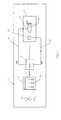
- Figure 1shows the installation of tests according to the present invention comprising its main building blocks.
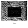
- FIG. 2represents the image of a screen of control presenting the configuration and execution menu for the touch screen.
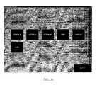
- FIG. 3represents the image of a screen of control presenting the general configuration menu and of the E.C.M.
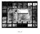
- FIG. 4represents the image of a screen of control presenting the organ configuration menu E.C.M. from another machine.
- FIG. 5represents the image of the screen of configuration of engine names.
- Figure 6shows the image of a page touch screen during operation of the E.C.M.
- Figure 7shows the image of the first window in the "Touch Button Configuration" section, allowing to choose the engine for which the configuration is intended.
- Figure 8shows the window image allowing you to choose one of the 25 pages to configure.
- Figure 9shows the window image to define the text and the text color as well as the background color of the buttons and their LEDs respectively.
- Figure 10shows the window image configuration obtained by "double-clicking" on a button in Figure 9.
- Figure 11shows the window image for monitoring the state of the test bench and the engine in real time when the E.C.M.
- Figure 12shows the image of the first window in the "LED Configuration" section, allowing to choose the engine for which the configuration is intended.
- Figure 13shows the window image allowing you to choose one of the 49 LEDs to configure, by "double-click" on each of these.
- Figure 14shows the image of the first window of the "Configuration of Actions" section, allowing to choose the engine for which the configuration is intended.
- Figure 15shows the window image to choose one of the buttons to configure, to sending an order message (25 pages of 100 buttons).
- Figure 16shows the image of an example action sequence configuration window, obtained by "double-clicking" on the selected button.
- FIG. 1schematically describes a test facility 1 according to the present invention.
- Sheessentially comprises a test bench 7 presenting itself in the form of a chamber in which is placed a 100 engine.
- This test benchis controlled by a command and control 5 (E.C.M.) which, on the basis information (digital or analog inputs 23) transmitted by sensors 11, acts on actuators 9 (digital outputs 21).
- the operatorcontrols the command and control 5 via a plate 3 control and display interface between the operator 10 and the command and control member 5 essentially provided with push buttons 31 and LEDs 35.
- the E.C.M. programmablebasically consists of two systems independent, an operator interface 3 and a command and control 5, which interact with each other by communication channels.
- the setis fully configurable, both for commands and for checks of the organs (sensors + actuators) of the bench and the engine to be tested.
- the operator interfaceallows you to enter commands or command sequences using a screen touch or mouse, view the status of buttons control elements which are represented on the screen by lights 35 and activate, on the same screen, lights characterizing the state of the system according to the actions which have been requested by the operator.
- buttons and indicatorsare fully configurable by the operator both in terms of colors as labels.
- the second device, control and E.C.M. properin a configuration standard, can control and control inputs or outputs discrete (optocoupled inputs, relay or SSR outputs, etc.).
- the E.C.M.also controls remote intelligent control modules, equipped with microprocessors actuating relay type outputs, by through a field bus.
- the command and control bodyis coupled with a display screen which allows to display in permanent LEDs representing the status of the process controlled and controlled by the E.C.M.
- LEDscan be configured and configured by the user according to the test at and the engine to be tested.
- the state of all digital system inputs, reflecting the state of the bench and engine controls,is monitored in permanence in relation to the forecast statements described by the user at the configuration level. Alarms detected are displayed in real time on this screen.
- a touch screenserves operator interface. So this is the input device operator commands, which is configurable and programmable as pages, each page displayed viewable with 25 buttons and 25 indicators. He ... not therefore has practically no limitation on the number pushbuttons and indicators available.
- the exchange of order information between the operator interface and the steering and control unitis done through communication channels between the two systems.
- Pressing a screen control button touchcauses the generation of a series of actions and controls at the E.C.M. This one attacks the actuators directly and checks the status of the sensors.
- the systemmay send the operator interface (touch screen) instant result of the condition monitoring process of the test bench and of the engine under test, in order to restore display on the touch screen.
- the computer associated with the E.C.M. Eastequipped with input / output cards which can be configured as input or output according to the needs of installation.
- the digital input / output signalsare conditioned to guarantee the galvanic isolation of the E.C.M. in relation to the bench / engine environment.
- the E.C.M.consists of a computer which manages the digital inputs and outputs of different sensors and actuators of a test bench and his engine. It is provided with a display system for check the state of the bench at all times and ensure its monitoring by controlling all alarms that could occur in the test bench or at the turbojet engine under test.
- the human-machine interfaceis in most applications consisting of the touch screen where software push buttons are shown.
- the touch screenhas a number of separate sensitive areas, each corresponding to a push button, itself characterized by a color determined and on which appears a text representative of the action to trigger.
- a messageis sent to the E.C.M. by a line of serial communication (RS-232, Ethernet, ).
- This messageis decoded by the E.C.M. which contains, for each button of the touch screen, a description file of the actions and controls to be carried out at the level of the test bench or engine.
- command messagescan also be sent by any other system capable of generating messages on a serial communication line which allows, in particular, to associate the E.C.M. to a system data acquisition and processing to allow the complete automation of a test without the intervention of a operator.
- Action files and action sequences to be createdare created using user-friendly configuration which facilitates encoding.
- the actions or controls to be performedare do, on the one hand, through cards digital inputs / outputs.
- Digital signals correspondentsare shaped and packaged in a electronic packaging device. These signals are galvanically isolated to prevent disturbance electromagnetic interference.
- the E.C.M.can, on the other hand, order the elements of a test bench using modules intelligent remote controls near the actuators order via a field bus.
- modules intelligent remote controlsnear the actuators order via a field bus.
- Each of these modulesis equipped with an integrated microcontroller which decodes the signals it receives from the fieldbus and actuates relays which control the contacts allowing to execute the actions to be carried out.
- the message sent to the E.C.M.contains the address of this button, and more precisely the coordinates of its position on the touch screen.
- the E.C.M.After receiving and decoding the received message, the E.C.M. checks if a (sequence of) action (s) has been predefined for this message and executes commands and checks requested on all inputs and outputs digital in connection with the test bench or the turbojet engine tested.
- This operating principlemakes the organ E.C.M., independent steering and supervisory body the turbojet engine to be tested and the bench in which test. It is completely versatile for all engines and all test benches.
- This test preparationcan be done on a station independent of the E.C.M. body, for example in the test engineer's office, during the bench test. Time savings are very important.
- the E.C.M.allows to configure a bench of tests for a certain type of engine.
- the list of these motorsis established by the "Name configuration" section motors "in the overall configuration menu.
- a configuration toolallows staff qualified to configure the hardware used. This tool allows you to modify the serial communication ports, in the event that a port becomes defective, or to modify the hardware device of the E.C.M. organ, for example add a remote intelligent module, add inputs analog, use fewer digital inputs for the benefit digital outputs, etc.
- the touch screenconsists of 25 buttons and 25 LEDs per page; it has a total of 25 pages.
- the Figure 6shows an example of a touch page when functioning of the E.C.M.
- Configuration of the touch interfaceis done using the “Configuration of Touch buttons "in the” TouchScreen “menu ( Figure 2). This tool allows you to define the different pages containing the 25 action buttons.
- the first window that appearsallows you to choose the engine for which the configuration is intended (Figure 7); the second window allows you to choose one of the 25 pages to configure (Figure 8); the third window allows you to define the text of the buttons and their indicators as well as the color of the text and the background of the button ( Figure 9).
- the upper left buttonis used, in the functioning of the E.C.M. for page change (figure 9). It is therefore reserved for this purpose.
- page 25is used for choosing of page, which limits the choice to 24 pages, the button lower right being reserved for blocking / unblocking the touch screen (figure 8) to avoid sending commands not wanted by the operator in some critical phases of the test (safety).
- the E.C.M.(commands and controls) is made up of 49 indicators which correspond to real-time monitoring of the state of test bench and its engine according to the defined inputs by the user at the time of configuration.
- An example of monitoring page during the functioning of the organ E.C.M.is given in figure 11.
- the interface configuration of visualization of the E.C.M.is done using the "LED Configuration" section of the E.C.M. This tool allows you to configure the 49 indicators on the viewing.
- the first windowallows you to choose the motor for which the configuration is intended ( Figure 12).
- the second windowpresents the 49 indicators of the organ E.C.M. in the OFF state. Just "double-click” on the LED of his choice to configure it ( Figure 13).
- the indicators of the display screenindicate the result in real time of the monitoring of the physical state of an entry, for a particular phase of the test, as described in the configuration of the E.C.M. To do this, each indicator on the visualization must be assigned to a physical input to monitor.
- An indicatorcan be linked to a digital input or an analog expression, such as the LED "Fuel Pump” is connected to the analog input ANA 3 which represents the state of the fuel pump sensor.
- a black rectangle located in the lower right corner of the LEDindicates whether it is already connected to an input (figure 13).
- the ON state of the indicatorcorresponds to the state of the indicator in default. For example, if the first LED is connected at the first digital input and that this input is monitored low, the indicator will be in the fault position (ON) if the digital input is supplied and vice versa.
- the configuration of the action sequences of the E.C.M.is done using an interface drop-down menu in the "Configuration" section Actions "from the E.C.M. menu. This tool allows you to configure the sequences of actions relating to the different buttons.
- a first windowallows you to choose the motor for which the configuration is intended ( Figure 14).
- the second window( Figure 15) allows you to choose the button to configure.
- This windoware represented all the buttons accessible for sending a command message. They are characterized by their coordinates (row - column).
- the first 25, from B11 to B55are those that are visible on the touch screen and therefore accessible to the operator.
- the othersare so-called buttons "virtual", not visible on the screen, but which allow launch actions and action sequences using the same principle.
- buttonsvisible or virtual, can have two states, the first corresponding to the state “pressed”, the second in the “released” state.
- the devicealso makes it possible to define 25 screen pages, which offers a very important possibility system configuration (equivalent to 5000 messages from ordered).
- the action filecan then be configured ("Button action” section).
- the systemallows, by configuration, that one of the actions associated with a button can launch an order corresponding to another button, which allows you to perform action sequences very complex by nesting in a sequence of actions a sequence corresponding to another command than that In progress.
- This mechanismthus allows piloting automatic conditional without requiring the intervention of the operator.
- Each page of the touch screenbeing composed 100 buttons of which 75 are virtual, these allow you to define actions that will be executed automatically by the E.C.M. and make certain stages of the fully recursive test.
- the structure of the configuration file for actionsresumes, for each column corresponding to a sequence of actions, the complete and exhaustive description of all inputs, all outputs, all analog values, all timings, alarms at monitor, etc. necessary to define the state of operation in which the operator wants the components of the test bench and the turbojet are a specific point in the test.
- B561is the ON state button located in line 5 column 6 page 1, so this is a button here virtual because it exceeds the maximum coordinates of a touch screen button.
- Figure 16gives an example of a window configuration of action sequences.
- the E.C.M.When connected to the system test bench data acquisition, the E.C.M. at the ability to control analog values (such as the meal). You must indicate the wording you want check in the "Identification” column (eg PLA), with the syntax identical to that used in the database data from the acquisition system, and enter an expression comparison type "> 27.5", for example. The organ E.C.M. will then wait until the PLA is greater than 27.5 ° to take the next action.
- the "Identification” columneg PLA
- the organ E.C.M.will then wait until the PLA is greater than 27.5 ° to take the next action.
- Analog controlis similar to control of digital inputs, the user has the possibility of performing a specific action in case of "Time Out” or in the event of a fault.
- the E.C.M.has digital outputs (discrete) to order certain components of the bench or engine.
- the E.C.M.also has modules deported smart who are smart actuators controlling four relays via a bus ground. These control certain organs of the bench or engine.
- the E.C.M.can set the state of a touch screen button (operator interface) in ON state or OFF.
- the userhas the possibility to prohibit the action a command button (Inhibited) or to force the organ E.C.M. to wait until he positions a button in a certain state (Wait On, Wait OFF).
- the E.C.M.can set the state of a touch screen light.
- the unit of "timing" usedis the millisecond.
- the "Actions” parameterdesignates a sequence of actions to be executed if the E.C.M. is in “Time Out” waiting for an event ("Hold High”, “Hold Low”, etc.). This parameter must follow the syntax Bxyz (Ex: B651).
- This buttondisplays the column “Wiring” which allows you to quickly view the input / output connections.
- help buttons configurationhas been introduced in the menu so that facilitate system configuration. Their functionality is described below.
- This buttondisplays the column “Wiring” which allows you to quickly view the input / output connections.
- buttonsallow you to place values initials for inputs / outputs, which correspond to the security configuration of the bench.
- the initial stateis used to monitor the inputs or position the outputs directly at the start of the E.C.M .. organ
- the action fileis not modified and saved only when the operator clicks this button.
- This buttonallows you to return to the window previous to configure another action file.
- Table 1gives the sequence of actions performed when the button "B12.1" is activated.
- the state of digital input 8is expected at a "Low” level because before pressing the button 12.1 this contact should already be in the “Down” position. Valve firewall should also be positioned open so the expected state is “High” on entry 4 before the button 12.1 is not pressed. Pressing the button 12.1 can therefore activate contact 1 of the remote module 1 ("ADAM 1"), which will operate the fuel pump switch. If this one is activated, it returns a "High” state on input 2 which must position the pump light on "ON”.
- ADAM 1remote module 1
Landscapes
- Chemical & Material Sciences (AREA)
- Engineering & Computer Science (AREA)
- Combustion & Propulsion (AREA)
- Physics & Mathematics (AREA)
- General Physics & Mathematics (AREA)
- Testing Of Engines (AREA)
Abstract
Description
Translated fromFrenchLa présente invention se rapporte à uneinstallation comprenant un banc d'essais pour laréalisation de tests de moteurs d'avion.The present invention relates to ainstallation including a test bench foraircraft engine testing.
Plus particulièrement, la présente inventionse rapporte à l'organe de commande et de contrôle desdifférents éléments nécessaires à la mise en condition d'unbanc d'essais pour la réalisation de tests de moteursd'avion. Ces moteurs d'avion peuvent être desturboréacteurs, des turbopropulseurs, etc.More particularly, the present inventionrelates to the command and control organ ofdifferent elements necessary to condition atest bench for carrying out engine testsairline. These aircraft engines can beturbojets, turbopropellers, etc.
La présente invention se rapporte égalementau procédé de programmation et de configuration del'interface opérateur à écran tactile de l'organe decommande et de contrôle présent sur le banc d'essais.The present invention also relatesto the programming and configuration process ofthe touch screen operator interface of thecommand and control present on the test bench.
Les moteurs tels que les turboréacteurs etles turbopropulseurs doivent être soumis à une série detests sur banc d'essais afin que l'on puisse vérifier leurscaractéristiques et leur comportement du point de vue tantmécanique qu'aérodynamique, tels que essais et contrôle derodage, de vérification de la poussée, de consommation,d'absence de vibrations, de contrôle des pompes àcarburant, du circuit d'air de démarrage, de la mise soustension des bougies, de l'état des portes, des volets, des circuits de servitude et de sécurité, etc. Dans ce but, cesmoteurs sont disposés et maintenus dans les bancs d'essaisà l'aide d'une structure support.Engines such as turbojets andturboprop engines must be subjected to a series oftests on the test bench so that we can check theircharacteristics and their behavior from the point of view so muchmechanical than aerodynamic, such as testing and controlrunning in, checking thrust, consumption,no vibrations, pump controlsfuel, starting air system, powering upvoltage of the candles, the condition of the doors, shutters,service and safety circuits, etc. For this purpose, theseengines are arranged and maintained in the test benchesusing a support structure.
Ces bancs d'essais sont commandés par desorganes de commande et de contrôle qui permettent, sur based'informations transmises par des capteurs et en agissantsur des actionneurs, d'effectuer la série prescrited'essais.These test benches are controlled bycommand and control devices which allow, on the basisof information transmitted by sensors and by actingon actuators, to perform the prescribed seriestest.
L'organe de commande, appelé E.C.M. (pourEngine Control Module), est donc le dispositif d'interfaceet de dialogue entre l'opérateur d'une part, et lescapteurs et actionneurs du banc d'essai et du moteur àtester d'autre part.The control unit, called ECM (forEngine Control Module ), is therefore the interface and dialogue device between the operator on the one hand, and the test bench and actuator sensors and actuators d 'somewhere else.
Dans sa version classique, l'organe decommande est associé à une platine, habituellementspécifique pour chaque type de moteur, munie d'un panneaude contrôle lui-même équipé de boutons-poussoirs qui, parl'intermédiaire de dispositifs électromécaniques (relaiscâblés et logique combinatoire), pilotent les différentséléments d'action sur le banc d'essais. Cet organe decommande est également équipé d'un panneau de visualisationà voyants indiquant à l'opérateur l'état du banc et dumoteur dans la phase d'essai en cours.In its classic version, the organ ofcommand is associated with a board, usuallyspecific for each type of engine, fitted with a panelcontrol itself fitted with push buttons which, bythrough electromechanical devices (relayswired and combinational logic), control the differentelements of action on the test bench. This organ ofcontrol is also equipped with a display panelwith indicators indicating to the operator the state of the bench andengine in the current test phase.
Cependant, dans l'état de la technique, onobserve la faible souplesse d'adaptation de ces platines àdes configurations d'essais de plus en plus variées. Enoutre, la diversité des différents types de moteurs àtester conduit à la conception de platines spécifiques quisont uniques par type de moteur. Il faut donc procéder à unchangement de platine spécifique à chaque changement detype de moteur.However, in the state of the art,observe the low flexibility of adaptation of these plates toincreasingly varied test configurations. Inin addition, the diversity of the different types of motorstesting leads to the design of specific turntables whichare unique by engine type. So you have tochange of stage specific to each change oftype of engine.
La présente invention vise à proposer uneinstallation d'essais possédant un organe de commande quipourrait être programmable et configurable par lesresponsables (opérateurs commandant les essais) en fonctiondes besoins spécifiques du test à effectuer.The present invention aims to provide atest facility having a control member whichcould be programmable and configurable bymanagers (operators ordering the tests) on dutyspecific needs of the test to be performed.
En outre, la présente invention vise àproposer une solution qui permet de limiter le nombre deplatines spécifiques et de ce fait à augmenter la diversitédes types de moteur à tester sur le même banc d'essais.Furthermore, the present invention aims topropose a solution which makes it possible to limit the number ofspecific turntables and thereby increase diversityengine types to be tested on the same test bench.
La présente invention vise également àproposer une solution qui permette d'assurer lasurveillance en temps réel du banc d'essais et du moteur.The present invention also aims topropose a solution that will ensure thereal-time monitoring of the test bench and the engine.
D'autres buts et avantages de la présenteinvention seront décrits ultérieurement.Other purposes and advantages of thisinvention will be described later.
La présente invention se rapporte à uneinstallation d'essais destinée à la réalisation de testssur des moteurs, de préférence des moteurs d'avions telsque turboréacteurs ou turbopropulseurs qui sont disposésdans un banc d'essais et qui sont en interaction avec desactionneurs et des capteurs constituant respectivement lessorties et les entrées d'un organe de commande et decontrôle qui est lui-même associé à des moyens permettantl'établissement, le contrôle et la visualisation du pointde fonctionnement dudit banc d'essais et dudit moteur entemps réel, caractérisée en ce que lesdits moyens pourl'établissement, le contrôle et la visualisationcomprennent au moins une interface opérateur, de préférenceà écran tactile, munie d'une pluralité de boutons-poussoirsprogrammables, chacun desdits boutons-poussoirs étantprogrammé de sorte que l'action de presser ledit bouton-poussoirdéclenche l'exécution d'une action ou séquence d'actions prédéfinie sur ledit moteur en fonctionnementet/ou ledit banc d'essais.The present invention relates to atest facility for carrying out testson engines, preferably aircraft engines suchthat turbojet or turboprop that are arrangedin a test bench and which interact withactuators and sensors respectively constituting theoutputs and inputs of a control andcontrol which is itself associated with means allowingestablishment, control and visualization of the pointof operation of said test bench and of said engine inreal time, characterized in that said means forestablishment, control and visualizationinclude at least one operator interface, preferablywith touch screen, provided with a plurality of push buttonsprogrammable, each of said push buttons beingprogrammed so that the action of pressing said push buttontriggers the execution of an action or sequencepredefined actions on said engine in operationand / or said test bench.
De préférence, l'interface opérateur comprendplusieurs pages de boutons-poussoirs programmables, et demanière avantageuse, une pluralité de boutons-poussoirsprogrammables appartenant à une même page n'est pas visiblesur l'écran tactile.Preferably, the operator interface includesmultiple pages of programmable push buttons, andadvantageously, a plurality of push buttonsprogrammable belonging to the same page is not visibleon the touch screen.
Avantageusement, l'action ou séquenced'actions déclenchée par l'action de presser un bouton-poussoircomprend l'activation d'au moins une autre actionou séquence d'actions associée à un autre bouton-poussoir.Advantageously, the action or sequenceof actions triggered by the action of pressing a push buttonincludes activating at least one other actionor sequence of actions associated with another push button.
De manière avantageuse, pour chaque bouton-poussoirvisible est associé un champ additionnel sous laforme d'un voyant, ledit voyant décrivant l'étatcorrespondant audit bouton-poussoir.Advantageously, for each push buttonvisible is associated with an additional field under theform of an indicator, said indicator describing the statecorresponding to said push button.
Dans l'installation selon l'invention,lesdits boutons-poussoirs (31) peuvent aussi bien êtreactivés sur l'écran tactile ou par l'intermédiaire d'unesouris d'ordinateur.In the installation according to the invention,said push buttons (31) may as well beactivated on the touch screen or through acomputer mouse.
Avantageusement, l'installation del'invention comporte des moyens pour envoyer un messagecodé sous forme ASCII par une ligne de communication sérieà ladite unité centrale de contrôle, par pression oucliquage sur un desdits boutons-poussoirs, ledit messageASCII comprenant au moins l'adresse dudit bouton-poussoir.Advantageously, the installation ofthe invention includes means for sending a messagecoded in ASCII form by a serial communication lineto said central control unit, by pressing orclick on one of said push-buttons, said messageASCII comprising at least the address of said push button.
Cette installation peut en outre comporterdes moyens, au niveau de l'unité centrale de contrôle,permettant de décoder ledit message ASCII et de luiassocier de manière univoque un fichier descriptif desactions et contrôles à réaliser au niveau du banc d'essaisou du moteur.This installation may also includemeans, at the level of the central control unit,for decoding said ASCII message and itselfunequivocally associate a descriptive file ofactions and controls to be carried out at the test benchor the engine.
Avantageusement, l'unité centrale de contrôleest câblée à une pluralité d'entités physiques situées auniveau du banc d'essais et/ou du moteur.Advantageously, the central control unitis wired to a plurality of physical entities located at thelevel of the test bench and / or engine.
De manière avantageuse, l'installationcomprend en outre au moins un module de commandeintelligent déporté près d'un actionneur et commandé parl'intermédiaire d'un bus de terrain.Advantageously, the installationfurther includes at least one control moduleintelligent remote near an actuator and controlled bythrough a field bus.
La présente invention se rapporte également àun procédé de programmation et de configuration del'ensemble interface opérateur / organe de contrôle et decommande d'une installation selon la présente invention,caractérisé en ce qu'il comprend les étapes suivantes :
- choisir un menu relatif à la gestion de l'écran tactile;
- définir un type de moteur;
- choisir au moins une page de boutons-poussoirs surl'écran tactile;
- définir, pour au moins un desdits boutons-poussoirs deladite page, à la fois pour l'état "On" et pour l'état"Off" dudit bouton-poussoir, le texte devant apparaítresur ledit bouton-poussoir, la couleur dudit texte, lacouleur de l'arrière-plan, le texte apparaissant dans lechamp de type voyant définissant ledit étatcorrespondant au bouton-poussoir, la couleur dudit texteet la couleur de l'arrière-plan dudit champ.
- choose a menu relating to the management of the touch screen;
- define an engine type;
- choose at least one page of push buttons on the touch screen;
- define, for at least one of said push buttons on said page, both for the "On" state and for the "Off" state of said push button, the text to appear on said push button, the color of said text, the background color, the text appearing in the indicator type field defining said state corresponding to the push button, the color of said text and the background color of said field.
La présente invention concerne également unprocédé de programmation et de configuration de l'organe decommande et contrôle présent dans l'installation del'invention comprenant les étapes suivantes :
- choisir un menu relatif à la gestion de l'organe decommande et contrôle proprement dit;
- définir un type de moteur;
- choisir au moins une page de voyants sur l'écrantactile;
- définir, pour au moins un desdits voyants de laditepage, à la fois pour l'état "On" et pour l'état "Off"dudit voyant, le texte devant apparaítre sur ledit voyant, la couleur dudit texte et la couleur del'arrière-plan;
- définir de manière univoque l'entité physique associéeaudit voyant.
- choose a menu relating to the management of the command and control unit itself;
- define an engine type;
- choose at least one page of LEDs on the touch screen;
- define, for at least one of said indicators on said page, both for the "On" state and for the "Off" state of said indicator, the text to appear on said indicator, the color of said text and the color of the 'background;
- unequivocally define the physical entity associated with said indicator.
Ce procédé de programmation et configurationpeut en outre comprendre les étapes suivantes :
- définir un type de moteur;
- choisir au moins une page de boutons-poussoirs decommande;
- associer de manière univoque au moins un bouton-poussoirà une entité physique du banc d'essais ou du moteur;
- définir de manière univoque, pour ladite entitéphysique, au moins une action programmée, correspondantà un changement d'état de ladite entité physique.
- define an engine type;
- choose at least one page of control pushbuttons;
- unequivocally associate at least one push button with a physical entity of the test bench or of the engine;
- unequivocally define, for said physical entity, at least one programmed action, corresponding to a change of state of said physical entity.
De préférence, ladite entité physiqueappartient au groupe constitué par une entrée digitale, unesortie digitale, une entrée analogique, un moduleintelligent déporté, un bouton-poussoir tactile et unvoyant tactile.Preferably, said physical entitybelongs to the group consisting of a digital input, adigital output, analog input, modulesmart remote, a touch button and atouch light.
De préférence, ladite action ou séquenced'actions comprend la définition d'au moins une action ouséquence d'actions associée à l'activation d'au moins unautre bouton-poussoir.Preferably, said action or sequenceof actions includes the definition of at least one action orsequence of actions associated with the activation of at least oneanother push button.
Avantageusement, un temps mort est définientre deux actions ou séquences d'actions consécutives dansle temps.Advantageously, a dead time is definedbetween two consecutive actions or sequences of actions intime.
De manière avantageuse, une durée maximaleest définie, durant laquelle une action ou séquenced'actions doit être entièrement réalisée, faute de quoi uneaction ou séquence d'actions alternative est réalisée,après dépassement de ladite durée maximale.Advantageously, a maximum durationis defined, during which an action or sequenceof actions must be fully carried out, failing which aalternative action or sequence of actions is performed,after exceeding said maximum duration.
Un tel organe de commande et contrôleprésente plusieurs avantages. Un de ces avantages est qu'ilest configurable pour tous types de moteurs (turboréacteur,turbopropulseur, etc.) et pour toute configuration du bancd'essais, ce qui simplifie grandement les procédures devérification.Such a command and control bodyhas several advantages. One of these advantages is thatis configurable for all types of engines (turbojet,turboprop, etc.) and for any bench configurationwhich greatly simplifies the procedures forverification.
Cet organe permet également d'assurer unesurveillance en temps réel de l'état du banc et du moteursur la base d'une séquence de l'essai préalablement définiepar l'opérateur.This body also ensures areal-time monitoring of bench and engine statusbased on a previously defined test sequenceby the operator.
Le langage d'interface entre l'opérateur etl'organe de commande et de contrôle utilisé pour piloterledit organe ou pour en obtenir des informations est unlangage facilement compréhensible et ne présente pourl'opérateur aucune difficulté d'adaptation.The interface language between the operator andthe command and control unit used to controlsaid organ or to obtain information from it is aeasily understandable language and only present forthe operator no difficulty in adapting.
La figure 1 représente l'installationd'essais selon la présente invention comprenant sesprincipaux éléments constitutifs.Figure 1 shows the installationof tests according to the present invention comprising itsmain building blocks.
La figure 2 représente l'image d'un écran decontrôle présentant le menu de configuration et d'exécutionpour l'écran tactile.FIG. 2 represents the image of a screen ofcontrol presenting the configuration and execution menufor the touch screen.
La figure 3 représente l'image d'un écran decontrôle présentant le menu général de configuration etd'exécution de l'organe E.C.M.FIG. 3 represents the image of a screen ofcontrol presenting the general configuration menu andof the E.C.M.
La figure 4 représente l'image d'un écran decontrôle présentant le menu de configuration de l'organeE.C.M. à partir d'une autre machine.FIG. 4 represents the image of a screen ofcontrol presenting the organ configuration menuE.C.M. from another machine.
La figure 5 représente l'image de l'écran deconfiguration des noms de moteurs.FIG. 5 represents the image of the screen ofconfiguration of engine names.
La figure 6 représente l'image d'une paged'écran tactile lors du fonctionnement de l'organe E.C.M.Figure 6 shows the image of a pagetouch screen during operation of the E.C.M.
La figure 7 représente l'image de la premièrefenêtre de la section "Configuration des Boutons tactiles",permettant de choisir le moteur pour lequel laconfiguration est destinée.Figure 7 shows the image of the firstwindow in the "Touch Button Configuration" section,allowing to choose the engine for which theconfiguration is intended.
La figure 8 représente l'image de la fenêtrepermettant de choisir une des 25 pages à configurer.Figure 8 shows the window imageallowing you to choose one of the 25 pages to configure.
La figure 9 représente l'image de la fenêtrepermettant de définir le libellé et la couleur du texteainsi que la couleur d'arrière-plan des boutons et de leursvoyants respectivement.Figure 9 shows the window imageto define the text and the text coloras well as the background color of the buttons and theirLEDs respectively.
La figure 10 représente l'image de la fenêtrede configuration obtenue en "double-cliquant" sur un boutonde la figure 9.Figure 10 shows the window imageconfiguration obtained by "double-clicking" on a buttonin Figure 9.
La figure 11 représente l'image de la fenêtrede surveillance de l'état du banc d'essais et du moteur entemps réel lors du fonctionnement de l'organe E.C.M.Figure 11 shows the window imagefor monitoring the state of the test bench and the engine inreal time when the E.C.M.
La figure 12 représente l'image de lapremière fenêtre de la section "Configuration des Voyants",permettant de choisir le moteur pour lequel laconfiguration est destinée.Figure 12 shows the image of thefirst window in the "LED Configuration" section,allowing to choose the engine for which theconfiguration is intended.
La figure 13 représente l'image de la fenêtrepermettant de choisir un des 49 voyants à configurer, en"double-cliquant" sur chacun de ceux-ci.Figure 13 shows the window imageallowing you to choose one of the 49 LEDs to configure, by"double-click" on each of these.
La figure 14 représente l'image de lapremière fenêtre de la section "Configuration des Actions",permettant de choisir le moteur pour lequel laconfiguration est destinée.Figure 14 shows the image of thefirst window of the "Configuration of Actions" section,allowing to choose the engine for which theconfiguration is intended.
La figure 15 représente l'image de la fenêtrepermettant de choisir un des boutons à configurer, pourl'envoi d'un message de commande (25 pages de 100 boutons).Figure 15 shows the window imageto choose one of the buttons to configure, tosending an order message (25 pages of 100 buttons).
La figure 16 représente l'image d'un exemplede fenêtre de configuration de séquence d'actions, obtenueen "double-cliquant" sur le bouton choisi.Figure 16 shows the image of an exampleaction sequence configuration window, obtainedby "double-clicking" on the selected button.
La figure 1 décrit schématiquement uneinstallation d'essais 1 selon la présente invention. Ellecomprend essentiellement un banc d'essais 7 se présentantsous la forme d'une chambre dans laquelle est disposé unmoteur 100. Ce banc d'essais est commandé par un organe decommande et de contrôle 5 (E.C.M.) qui, sur based'informations (entrées digitales ou analogiques 23)transmises par des capteurs 11, agit sur des actionneurs 9(sorties digitales 21). L'opérateur pilote l'organe decommande et de contrôle 5 par l'intermédiaire d'une platine3 de commande et de visualisation qui sert d'interfaceentre l'opérateur 10 et l'organe de commande et de contrôle5 munie essentiellement de boutons poussoirs 31 et devoyants 35.Figure 1 schematically describes a
La diversité des types de moteur à testerdans un même banc a conduit à la conception et laréalisation d'une installation d'essais munie d'un ensembleplatine / organe E.C.M. unique, qui peut être programmableet configurable par les responsables des essais en fonctionde leurs besoins.The diversity of engine types to be testedin one bench led to the design and therealization of a test facility equipped with a setplatinum / organ E.C.M. unique, which can be programmableand configurable by the test managers in functionof their needs.
L'ensemble platine / organe E.C.M.programmable se compose essentiellement de deux systèmesindépendants, une interface opérateur 3 et un organe decommande et de contrôle 5, qui dialoguent entre eux par descanaux de communication. L'ensemble est entièrementconfigurable, aussi bien pour les commandes que pour lescontrôles des organes (capteurs + actionneurs) du bancd'essais et du moteur à tester.The E.C.M.programmable basically consists of two systemsindependent, an
Il peut être adapté à tout banc et à touttype de moteur, pour autant que les capacités prises encompte soient correctement dimensionnées et ceci sansnécessiter aucune compilation de programmes spécifiques.It can be adapted to any bench and anyengine type, provided that the capacitiesaccount are correctly sized and this withoutrequire no compilation of specific programs.
L'interface opérateur permet d'entrer descommandes ou des séquences de commandes au moyen d'un écrantactile ou d'une souris, de visualiser l'état des boutonsde commande actifs qui sont représentés sur l'écran par desvoyants 35 et d'activer, sur le même écran, des voyantscaractérisant l'état du système en fonction des actions quiont été demandées par l'opérateur.The operator interface allows you to entercommands or command sequences using a screentouch or mouse, view the status of buttonscontrol elements which are represented on the screen by
Ces boutons et voyants sont entièrementconfigurables par l'opérateur aussi bien au niveau descouleurs que des libellés.These buttons and indicators are fullyconfigurable by the operator both in terms ofcolors as labels.
Le deuxième dispositif, organe de commande etde contrôle E.C.M. proprement dit, dans une configurationstandard, peut piloter et contrôler des entrées ou sortiesdiscrètes (entrées optocouplées, sorties par relais ou SSR,etc.).The second device, control andE.C.M. proper, in a configurationstandard, can control and control inputs or outputsdiscrete (optocoupled inputs, relay or SSR outputs,etc.).
L'organe E.C.M. contrôle également desmodules de commande intelligents déportés, équipés demicroprocesseurs actionnant des sorties de type relais, parl'intermédiaire d'un bus de terrain.The E.C.M. also controlsremote intelligent control modules, equipped withmicroprocessors actuating relay type outputs, bythrough a field bus.
L'organe de commande et de contrôle estcouplé à un écran de visualisation qui permet d'afficher enpermanence des voyants représentant à tout moment l'état duprocessus commandé et contrôlé par l'organe E.C.M.The command and control body iscoupled with a display screen which allows to display inpermanent LEDs representing the status of theprocess controlled and controlled by the E.C.M.
Ces voyants peuvent être configurés etparamétrés par l'utilisateur en fonction de l'essai àréaliser et du moteur à tester. L'état de l'ensemble desentrées digitales du système, reflétant l'état du bancd'essais et des commandes moteur, est surveillé enpermanence par rapport à des états prévisionnels décritspar l'utilisateur au niveau des configurations. Les alarmesdétectées sont visualisées en temps réel sur cet écran.These LEDs can be configured andconfigured by the user according to the test atand the engine to be tested. The state of alldigital system inputs, reflecting the state of the benchand engine controls, is monitored inpermanence in relation to the forecast statements describedby the user at the configuration level. Alarmsdetected are displayed in real time on this screen.
Lorsqu'une commande en provenance del'interface opérateur est détectée par l'organe E.C.M.,elle est décodée et déclenche le démarrage d'une séried'actions préprogrammées sur les actionneurs du banc et dumoteur.When an order fromthe operator interface is detected by the E.C.M.it is decoded and triggers the start of a seriesof preprogrammed actions on the actuators of the bench and theengine.
Selon une forme d'exécution particulièrementpréférée de l'invention, un écran tactile fait officed'interface opérateur. C'est donc le dispositif d'entréedes commandes opérateur, qui est configurable etprogrammable sous forme de pages, chaque page affichéevisualisable comportant 25 boutons et 25 voyants. Il neprésente donc pratiquement aucune limitation sur le nombrede boutons-poussoirs et de voyants disponibles.According to a particular embodimentpreferred of the invention, a touch screen servesoperator interface. So this is the input deviceoperator commands, which is configurable andprogrammable as pages, each page displayedviewable with 25 buttons and 25 indicators. He ... nottherefore has practically no limitation on the numberpushbuttons and indicators available.
Les échanges d'informations de commande entrel'interface opérateur et l'organe de pilotage et contrôlese fait par des canaux de communication entre les deuxsystèmes.The exchange of order information betweenthe operator interface and the steering and control unitis done through communication channels between the twosystems.
L'appui sur un bouton de commande de l'écrantactile provoque la génération d'une série d'actions et decontrôles au niveau de l'organe E.C.M. Celui-ci attaquedirectement les actionneurs et vérifie l'état des capteurs.En fonction de la configuration du système, celui-ci peutrenvoyer à l'interface opérateur (écran tactile) lerésultat instantané du processus de surveillance de l'étatdu banc d'essais et du moteur en test, afin de remettre àjour la visualisation sur l'écran tactile.Pressing a screen control buttontouch causes the generation of a series of actions andcontrols at the E.C.M. This one attacksthe actuators directly and checks the status of the sensors.Depending on the system configuration, the system maysend the operator interface (touch screen)instant result of the condition monitoring processof the test bench and of the engine under test, in order to restoredisplay on the touch screen.
Après validation visuelle par l'opérateur,une nouvelle série d'actions peut être initiée.After visual validation by the operator,a new series of actions can be initiated.
L'ordinateur associé à l'organe E.C.M. estéquipé de cartes d'entrées/sorties qui peuvent êtreconfigurées en entrée ou en sortie suivant les besoins del'installation. Les signaux digitaux d'entrées/sorties sont conditionnés pour garantir l'isolation galvanique del'organe E.C.M. par rapport à l'environnement banc/moteur.The computer associated with the E.C.M. Eastequipped with input / output cards which can beconfigured as input or output according to the needs ofinstallation. The digital input / output signals areconditioned to guarantee the galvanic isolation ofthe E.C.M. in relation to the bench / engine environment.
En résumé, l'organe E.C.M. présente lescaractéristiques suivantes :
- il constitue l'interface entre l'opérateur et leséléments du banc d'essais et du moteur;
- il est entièrement configurable par l'opérateur pourtout type de moteur;
- les commandes sont entrées par l'écran tactile et/ou lasouris;
- les commandes peuvent être générées par liaison série;
- les boutons de commande sont visualisés sur un écran;
- l'interface opérateur travaille en multi-pages;
- le système est configurable par un personnel sansconnaissances informatiques préalables;
- il est doté d'une interface conviviale, par exemple detype Microsoft® Windows™.
- it constitutes the interface between the operator and the elements of the test bench and the engine;
- it is fully configurable by the operator for any type of engine;
- commands are entered via the touch screen and / or the mouse;
- commands can be generated by serial link;
- the control buttons are displayed on a screen;
- the operator interface works in multi-pages;
- the system is configurable by personnel without prior computer knowledge;
- it has a user-friendly interface, for example of the Microsoft® Windows ™ type.
L'organe E.C.M. est constitué d'un ordinateurqui gère les entrées et les sorties digitales desdifférents capteurs et actionneurs d'un banc d'essais et deson moteur. Il est muni d'un système de visualisation pourcontrôler à tout moment l'état du banc et en assure lasurveillance en contrôlant toutes les alarmes quipourraient survenir dans le banc d'essais ou au niveau duturboréacteur en cours d'essai.The E.C.M. consists of a computerwhich manages the digital inputs and outputs ofdifferent sensors and actuators of a test bench andhis engine. It is provided with a display system forcheck the state of the bench at all times and ensure itsmonitoring by controlling all alarms thatcould occur in the test bench or at theturbojet engine under test.
Il est connecté à un autre dispositifpermettant à l'opérateur de lancer des actions ou desséquences d'actions à réaliser pour assurer le pilotageautomatique de l'essai. L'interface homme-machine est dansla plupart des applications constitué de l'écran tactile oùsont représentés des boutons-poussoirs logiciels.It is connected to another deviceallowing the operator to launch actions orsequences of actions to be carried out to ensure steeringautomatic test. The human-machine interface is inmost applications consisting of the touch screen wheresoftware push buttons are shown.
L'écran tactile comporte un certain nombre dezones sensibles distinctes, correspondant chacune à unbouton-poussoir, lui-même caractérisé par une couleurdéterminée et sur lequel figure un texte représentatif del'action à déclencher.The touch screen has a number ofseparate sensitive areas, each corresponding to apush button, itself characterized by a colordetermined and on which appears a text representative ofthe action to trigger.
Au toucher d'un bouton poussoir, un messageest envoyé vers l'organe E.C.M. par une ligne decommunication série (RS-232, Ethernet,...). Ce message estdécodé par l'organe E.C.M. qui contient, pour chaque boutonde l'écran tactile, un fichier descriptif des actions etdes contrôles à réaliser au niveau du banc d'essais ou dumoteur.At the touch of a push button, a messageis sent to the E.C.M. by a line ofserial communication (RS-232, Ethernet, ...). This message isdecoded by the E.C.M. which contains, for each buttonof the touch screen, a description file of the actions andcontrols to be carried out at the level of the test bench orengine.
Ces messages de commande peuvent égalementêtre envoyés par tout autre système capable de générer desmessages sur une ligne de communication sérielle ce quipermet, notamment, d'associer l'organe E.C.M. à un systèmed'acquisition et de traitement de données pour permettrel'automatisation complète d'un essai sans intervention d'unopérateur.These command messages can alsobe sent by any other system capable of generatingmessages on a serial communication line whichallows, in particular, to associate the E.C.M. to a systemdata acquisition and processing to allowthe complete automation of a test without the intervention of aoperator.
Les fichiers d'actions et séquences d'actionsà réaliser sont créés par l'intermédiaire d'un logiciel deconfiguration convivial qui facilite l'encodage.Action files and action sequencesto be created are created usinguser-friendly configuration which facilitates encoding.
Les actions ou les contrôles à effectuer sefont, d'une part, par l'intermédiaire de cartesd'entrées/sorties digitales. Les signaux digitauxcorrespondants sont mis en forme et conditionnés dans undispositif électronique de conditionnement. Ces signauxsont isolés galvaniquement pour éviter toute perturbationélectromagnétique parasite.The actions or controls to be performed aredo, on the one hand, through cardsdigital inputs / outputs. Digital signalscorrespondents are shaped and packaged in aelectronic packaging device. These signalsare galvanically isolated to prevent disturbanceelectromagnetic interference.
L'organe E.C.M. peut, d'autre part, commanderles éléments d'un banc d'essais à l'aide de modules decommande intelligents déportés près des actionneurs àcommander par l'intermédiaire d'un bus de terrain. Chacunde ces modules est équipé d'un microcontrôleur intégré qui décode les signaux qu'il reçoit du bus de terrain etactionne des relais qui contrôlent les contacts permettantd'exécuter les actions à réaliser.The E.C.M. can, on the other hand, orderthe elements of a test bench using modulesintelligent remote controls near the actuatorsorder via a field bus. Eachof these modules is equipped with an integrated microcontroller whichdecodes the signals it receives from the fieldbus andactuates relays which control the contacts allowingto execute the actions to be carried out.
Lorsque l'opérateur appuie sur un bouton del'écran tactile, le message envoyé à l'organe E.C.M.contient l'adresse de ce bouton, et plus précisément lescoordonnées de sa position sur l'écran tactile.When the operator presses a buttonthe touch screen, the message sent to the E.C.M.contains the address of this button, and more precisely thecoordinates of its position on the touch screen.
Après réception et décodage du message reçu,l'organe E.C.M. vérifie si une (séquence d')action(s) a étéprédéfinie pour ce message et exécute les commandes et lescontrôles demandés sur toutes les entrées et sortiesdigitales en liaison avec le banc d'essai ou leturboréacteur testé.After receiving and decoding the received message,the E.C.M. checks if a (sequence of) action (s) has beenpredefined for this message and executes commands andchecks requested on all inputs and outputsdigital in connection with the test bench or theturbojet engine tested.
Ce principe de fonctionnement rend l'organeE.C.M., organe de pilotage et de surveillance, indépendantdu turboréacteur à tester et du banc dans lequel se faitl'essai. Il est complètement polyvalent pour tous moteurset tous bancs d'essais.This operating principle makes the organE.C.M., independent steering and supervisory bodythe turbojet engine to be tested and the bench in whichtest. It is completely versatile for all enginesand all test benches.
Son adaptation à un essai particulier se faitpar simple configuration, à l'intérieur de fichiers, descommandes et contrôles à effectuer, sans nécessiter decompilation informatique.Its adaptation to a particular test is doneby simple configuration, within files, ofcommands and checks to be carried out, without requiringcomputer compilation.
Le grand avantage de cette façon de procéderréside dans le fait que de multiples essais correspondantsà des conditions très différentes peuvent être préparés àl'avance sur tout système permettant de générer desfichiers ASCII.The great advantage of this way of proceedingis that multiple corresponding trialsat very different conditions can be prepared toadvance on any system to generateASCII files.
Cette préparation d'essai peut être faite surune station indépendante de l'organe E.C.M., par exempledans le bureau de l'ingénieur d'essai, pendant laréalisation d'un essai au banc. Les gains de temps obtenussont très importants.This test preparation can be done ona station independent of the E.C.M. body, for examplein the test engineer's office, during thebench test. Time savingsare very important.
L'organe E.C.M. met à la disposition desutilisateurs trois menus d'utilisation (programmation sousMicrosoft® Windows™). Ces menus sont les suivants :
- un menu, représenté à la figure 2, pour la configurationde l'interface opérateur et pour l'exécution desopérations, par l'intermédiaire de l'écran tactile et/oude la souris (TouchScreen) ;
- un menu, représenté à la figure 3, pour la configurationde l'organe E.C.M. lui-même et l'exécution des actionset contrôles de l'organe E.C.M.;
- un menu, représenté à la figure 4, pour la configurationde l'ensemble du système permettant de configurerl'organe E.C.M. à partir d'une autre machine (parexemple dans un bureau).
- a menu, represented in FIG. 2, for the configuration of the operator interface and for the execution of the operations, via the touch screen and / or the mouse (TouchScreen );
- a menu, represented in FIG. 3, for the configuration of the ECM member itself and the execution of the actions and controls of the ECM member;
- a menu, represented in FIG. 4, for the configuration of the entire system making it possible to configure the ECM member from another machine (for example in an office).
L'organe E.C.M. permet de configurer un bancd'essais pour un certain type de moteur. La liste de cesmoteurs est établie par la section "Configuration du nomdes moteurs" dans le menu de configuration d'ensemble.The E.C.M. allows to configure a benchof tests for a certain type of engine. The list of thesemotors is established by the "Name configuration" sectionmotors "in the overall configuration menu.
Il est possible soit d'ajouter (maximum 10),soit de supprimer des moteurs avec les boutons "Add" et"Del" (Figure 5).It is possible either to add (maximum 10),either delete engines with the "Add" buttons and"Del" (Figure 5).
Un outil de configuration permet au personnelqualifié de configurer le matériel (hardware) utilisé. Cetoutil permet de modifier les ports de communication série,au cas où un port deviendrait défectueux, ou de modifier ledispositif matériel de l'organe E.C.M., par exemple ajouterun module intelligent déporté, ajouter des entrées analogiques, utiliser moins d'entrées digitales au profitde sorties digitales, etc.A configuration tool allows staffqualified to configure the hardware used. Thistool allows you to modify the serial communication ports,in the event that a port becomes defective, or to modify thehardware device of the E.C.M. organ, for example adda remote intelligent module, add inputsanalog, use fewer digital inputs for the benefitdigital outputs, etc.
L'écran tactile est composé de 25 boutons etde 25 voyants par page; il dispose en tout de 25 pages. Lafigure 6 représente un exemple d'une page tactile lors dufonctionnement de l'organe E.C.M.The touch screen consists of 25 buttons and25 LEDs per page; it has a total of 25 pages. TheFigure 6 shows an example of a touch page whenfunctioning of the E.C.M.
La configuration de l'interface tactiles'effectue à l'aide de la section "Configuration desBoutons tactiles" dans le menu "TouchScreen" (figure 2).Cet outil permet de définir les différentes pages contenantles 25 boutons d'actions.Configuration of the touch interfaceis done using the "Configuration ofTouch buttons "in the" TouchScreen "menu (Figure 2).This tool allows you to define the different pages containingthe 25 action buttons.
La première fenêtre qui apparaít permet dechoisir le moteur pour lequel la configuration est destinée(Figure 7); la deuxième fenêtre permet de choisir une des25 pages à configurer (Figure 8); la troisième fenêtrepermet de définir le texte des boutons et de leurs voyantsainsi que la couleur du texte et de l'arrière-plan dubouton (Figure 9).The first window that appears allows you tochoose the engine for which the configuration is intended(Figure 7); the second window allows you to choose one of the25 pages to configure (Figure 8); the third windowallows you to define the text of the buttons and their indicatorsas well as the color of the text and the background of thebutton (Figure 9).
Pour configurer un bouton et son voyant, ilsuffit de "double-cliquer" sur le bouton choisi. Unefenêtre de configuration donnée est présentée comme sur lafigure 10.To configure a button and its indicator, itjust "double-click" on the selected button. Agiven configuration window is presented as on thefigure 10.
L'exemple repris sur la figure 10 est celuidu bouton jaune "NORMAL MODE" au milieu de l'écran de lafigure 8. L'utilisateur définit dans la fenêtre "Propriétédu Bouton" respectivement le libellé et la couleur dutexte, ainsi que la couleur de l'arrière-plan (fond) pourle bouton et le voyant.The example shown in Figure 10 is thatthe yellow "NORMAL MODE" button in the middle of the screenfigure 8. The user defines in the "Property" windowbutton "respectively the label and the color of thetext, as well as the background color forthe button and the indicator.
On remarquera que le bouton supérieur gaucheest utilisé, dans le fonctionnement de l'organe E.C.M.,pour le changement de page (figure 9). Il est donc réservéà cet effet. De même, la page 25 est utilisée pour le choix de page, ce qui limite le choix à 24 pages, le boutoninférieur droit étant réservé au blocage/déblocage del'écran tactile (figure 8) afin d'éviter l'envoi decommandes non souhaitées par l'opérateur dans certainesphases critiques de l'essai (sécurité).Note that the upper left buttonis used, in the functioning of the E.C.M.for page change (figure 9). It is therefore reservedfor this purpose. Similarly, page 25 is used for choosingof page, which limits the choice to 24 pages, the buttonlower right being reserved for blocking / unblockingthe touch screen (figure 8) to avoid sendingcommands not wanted by the operator in somecritical phases of the test (safety).
L'écran de visualisation de l'organe E.C.M.(commandes et contrôles) est composé de 49 voyants quicorrespondent à la surveillance en temps réel de l'état dubanc d'essais et de son moteur selon les entrées définiespar l'utilisateur au moment de la configuration. Un exemplede page de surveillance lors du fonctionnement de l'organeE.C.M. est donné par la figure 11.The E.C.M.(commands and controls) is made up of 49 indicators whichcorrespond to real-time monitoring of the state oftest bench and its engine according to the defined inputsby the user at the time of configuration. An exampleof monitoring page during the functioning of the organE.C.M. is given in figure 11.
La configuration de l'interface devisualisation de l'organe E.C.M. s'effectue à l'aide de lasection "Configuration des Voyants" du Menu E.C.M. Cetoutil permet de configurer les 49 voyants de l'écran devisualisation.The interface configuration ofvisualization of the E.C.M. is done using the"LED Configuration" section of the E.C.M. Thistool allows you to configure the 49 indicators on theviewing.
La première fenêtre permet de choisir lemoteur pour lequel la configuration est destinée (Figure12). La seconde fenêtre présente les 49 voyants de l'organeE.C.M. dans l'état OFF. Il suffit de "double-cliquer" surle voyant de son choix pour le configurer (Figure 13).The first window allows you to choose themotor for which the configuration is intended (Figure12). The second window presents the 49 indicators of the organE.C.M. in the OFF state. Just "double-click" onthe LED of his choice to configure it (Figure 13).
Les voyants de l'écran de visualisationindiquent le résultat en temps réel de la surveillance del'état physique d'une entrée, pour une phase particulièrede l'essai, tel que décrit dans la configuration del'organe E.C.M. Pour ce faire, chaque voyant de l'écran devisualisation doit être affecté à une entrée physique àsurveiller.The indicators of the display screenindicate the result in real time of the monitoring ofthe physical state of an entry, for a particular phaseof the test, as described in the configuration ofthe E.C.M. To do this, each indicator on thevisualization must be assigned to a physical input tomonitor.
Un voyant peut être lié à une entrée digitaleou à une expression analogique, comme par exemple le voyant"Pompe Carburant" est relié à l'entrée analogique ANA 3 quireprésente l'état du capteur de la pompe à carburant. Unrectangle noir situé dans le coin inférieur droit du voyantindique si celui-ci est déjà relié à une entrée (figure13). L'état ON du voyant correspond à l'état du voyant encas de défaut. Par exemple, si le premier voyant est reliéà la première entrée digitale et que cette entrée estsurveillée à bas, le voyant sera en position défaut (ON) sil'entrée digitale est alimentée et inversement.An indicator can be linked to a digital inputor an analog expression, such as the LED"Fuel Pump" is connected to the
Si le voyant de l'organe E.C.M. doitsurveiller une entrée directement au lancement du système,il faudra établir l'état initial de l'entrée reliée àcelui-ci dans la programmation des actions (voir ci-dessous).If the indicator light of the E.C.M. mustmonitor an entry directly when the system is launched,it will be necessary to establish the initial state of the input connected tothis in the programming of actions (see below).
La configuration des séquences d'actions del'organe E.C.M. s'effectue à l'aide d'une interfacelogicielle à menus déroulants de la section "Configurationdes Actions" du menu E.C.M. Cet outil permet de configurerles séquences d'actions relatives aux différents boutons.The configuration of the action sequences ofthe E.C.M. is done using an interfacedrop-down menu in the "Configuration" sectionActions "from the E.C.M. menu. This tool allows you to configurethe sequences of actions relating to the different buttons.
Une première fenêtre permet de choisir lemoteur pour lequel la configuration est destinée (Figure14).A first window allows you to choose themotor for which the configuration is intended (Figure14).
La deuxième fenêtre (Figure 15) permet dechoisir le bouton à configurer. Dans cette fenêtre sontreprésentés tous les boutons accessibles pour l'envoi d'unmessage de commande. Ils sont caractérisés par leurscoordonnées (ligne - colonne). Les 25 premiers, de B11 àB55 sont ceux qui sont visibles sur l'écran tactile et doncaccessibles à l'opérateur. Les autres sont des boutons dits "virtuels", non visibles sur l'écran, mais qui permettentde lancer les actions et séquences d'actions en utilisantle même principe.The second window (Figure 15) allows you tochoose the button to configure. In this window arerepresented all the buttons accessible for sending acommand message. They are characterized by theircoordinates (row - column). The first 25, from B11 toB55 are those that are visible on the touch screen and thereforeaccessible to the operator. The others are so-called buttons"virtual", not visible on the screen, but which allowlaunch actions and action sequences usingthe same principle.
Chacun de ces boutons, visibles ou virtuels,peut avoir deux états, le premier correspondant à l'état"enfoncé", le second à l'état "relâché".Each of these buttons, visible or virtual,can have two states, the first corresponding to the state"pressed", the second in the "released" state.
Le dispositif permet également de définir 25pages d'écran, ce qui offre une possibilité très importantede configuration du système (équivalente à 5000 messages decommande).The device also makes it possible to define 25screen pages, which offers a very important possibilitysystem configuration (equivalent to 5000 messages fromordered).
Dans la pratique ,la configuration se fait enréalisant les étapes suivantes :
- choisir le numéro de page dans la section "Choix d'unepage" (figure 15) ;
- choisir le bouton qui lancera les actions parmi l'un des100 boutons, dont, pour mémoire, 25 sont visibles àl'écran et 75 sont virtuels. Le bouton B11 n'est jamaisappelé directement au niveau de l'écran tactile car ilest réservé à un changement de page. Dès lors, il peutêtre utilisé comme bouton virtuel;
- choisir ensuite l'état du bouton dans la section"Position du bouton" (ON ou OFF).
- choose the page number in the "Choose a page" section (figure 15);
- choose the button that will launch the actions from one of the 100 buttons, of which 25 are visible on the screen and 75 are virtual. The button B11 is never called directly on the touch screen because it is reserved for a page change. Therefore, it can be used as a virtual button;
- then choose the button state in the "Button position" section (ON or OFF).
Le fichier d'actions peut alors êtreconfiguré (section "Action sur le bouton").The action file can then beconfigured ("Button action" section).
Parmi les actions possibles, outre lescommandes et les contrôles, le système permet, parconfiguration, qu'une des actions associée à un boutonpuisse lancer une commande correspondante à un autrebouton, ce qui permet de réaliser des séquences d'actionstrès complexes en imbriquant dans une séquence d'actionsune séquence correspondant à une autre commande que celleen cours. Ce mécanisme permet ainsi de faire du pilotage conditionnel automatique sans nécessiter l'intervention del'opérateur.Among the possible actions, in addition tocommands and controls, the system allows, byconfiguration, that one of the actions associated with a buttoncan launch an order corresponding to anotherbutton, which allows you to perform action sequencesvery complex by nesting in a sequence of actionsa sequence corresponding to another command than thatIn progress. This mechanism thus allows pilotingautomatic conditional without requiring the intervention ofthe operator.
Chaque page de l'écran tactile étant composéede 100 boutons dont 75 sont virtuels, ceux-ci permettent dedéfinir des actions qui seront exécutées automatiquementpar l'organe E.C.M. et de rendre certaines étapes del'essai entièrement récursives.Each page of the touch screen being composed100 buttons of which 75 are virtual, these allow you todefine actions that will be executed automaticallyby the E.C.M. and make certain stages ofthe fully recursive test.
Si une action n'a pas pu être exécutée dansun délai préprogrammé, les boutons virtuels qui serontréférencés dans les séquences d'actions correspondantesseront redirigés vers d'autres séquences, alternatives, quiexécuteront des actions de correction.If an action could not be performed ina preprogrammed delay, the virtual buttons which willreferenced in the corresponding action sequenceswill be redirected to other alternative sequences, whichwill execute corrective actions.
La troisième fenêtre permet de définir lesactions que l'organe E.C.M. doit exécuter (figure 16). Elleest constituée d'une série de colonnes dont les rôles sontles suivants :
- la colonne "Libellé" reprend le nom des différentséléments du fichier d'actions : les entrées physiquesdes organes à surveiller, les sorties physiques àpositionner pour actionner les dispositifs de commandes,les relais des modules intelligents déportés, lesentrées analogiques à tester, etc.;
- la colonne "Identification" qui permet d'identifier plusprécisément un libellé (par ex. : "IN 2" est le contactdu contacteur de la pompe à carburant) ;
- la colonne "Câblage" qui permet d'avoir une vued'ensemble du câblage des entrées/sorties digitales del'organe E.C.M. (exemple : "IN 5" est câblée surl'entrée 4 de la carte digitale d'entrée du 1er tiroirdu conditionneur de signaux);
- les colonnes "Action" reprennent les différentes actionsà effectuer;
- la colonne "Etat Initial" représente l'état de l'organeE.C.M. à son lancement. Par exemple, le relaiscontrôlant les bougies d'allumage du moteur doit êtrefermé au lancement du système ou la pompe à carburantdoit être directement surveillée.
- the "Label" column shows the names of the different elements of the action file: the physical inputs of the organs to be monitored, the physical outputs to be positioned to activate the control devices, the relays of the remote intelligent modules, the analog inputs to be tested, etc .;
- the "Identification" column which makes it possible to identify more precisely a label (for example: "IN 2" is the contact of the contactor of the fuel pump);
- the "Wiring" column which gives an overview of the wiring of the digital inputs / outputs of the ECM unit (example: "IN 5" is wired to input 4 of the digital input card of the 1st signal conditioner drawer);
- the "Action" columns show the different actions to be performed;
- the "Initial State" column represents the state of the ECM unit when it is launched. For example, the relay controlling the engine spark plugs must be closed when the system is started or the fuel pump must be directly monitored.
La structure du fichier de configuration desactions reprend, pour chaque colonne correspondant à uneséquence d'actions, le descriptif complet et exhaustif detoutes les entrées, de toutes les sorties, de toutes lesvaleurs analogiques, de tous les timings, les alarmes àsurveiller, etc., nécessaires pour définir l'état defonctionnement dans lequel l'opérateur veut que leséléments du banc d'essai et du turboréacteur se trouvent àun moment bien précis de l'essai.The structure of the configuration file foractions resumes, for each column corresponding to asequence of actions, the complete and exhaustive description ofall inputs, all outputs, allanalog values, all timings, alarms atmonitor, etc. necessary to define the state ofoperation in which the operator wants thecomponents of the test bench and the turbojet area specific point in the test.
Le marquage d'un bouton de commande suit unesyntaxe particulière. Cette syntaxe sera utilisée lors dela configuration des séquences d'actions d'un bouton decommande pour faire référence à une séquence d'actions d'unautre bouton :
Bxyz ou bxyz,
où
Bxyz or bxyz,
or
Ainsi, par exemple, B561 est le bouton à l'état ON situé enligne 5 colonne 6 page 1, il s'agit donc ici d'un bouton virtuel car il dépasse les coordonnées maximales d'unbouton de l'écran tactile.So, for example, B561 is the ON state button located in
La figure 16 donne un exemple de fenêtre deconfiguration de séquences d'actions.Figure 16 gives an example of a windowconfiguration of action sequences.
L'organe E.C.M. possède une carted'acquisition capable de prendre en charge un nombred'entrées digitales déterminé au départ selon les besoinsde l'application. Pour chaque entrée et pour chaque actionprogrammée, l'utilisateur a le choix entre 5 états deconfiguration possibles qui sont :
- Inchangé : l'état de l'entrée correspondante n'influencepas le comportement du processus testé;
- Bas : l'entrée physique correspondante est surveilléedans l'état "Bas". Le voyant relié à cette entrée sepositionne à ON (on dit aussi en défaut) si l'entréepasse à l'état "Haut". En cas de défaut, l'utilisateur ala possibilité d'exécuter une séquence d'actionsindiquée dans "Actions défaut". Par exemple, B661 estune séquence d'actions en cas de défaut et correspond aubouton virtuel à l'état ON,
ligne 6,colonne 6,page 1; - Haut : l'entrée physique correspondante est surveilléedans l'état "Haut". Le voyant relié à cette entrée sepositionne à ON (on dit aussi en défaut) si l'entréepasse à l'état "Bas". En cas de défaut, l'utilisateur ala possibilité d'exécuter une séquence d'actionsindiquée dans "Actions défaut". Par exemple, b762 estune séquence d'actions en cas de défaut et correspond aubouton virtuel à l'état OFF,
ligne 7,colonne 6,page 2; - Attend Bas : l'organe E.C.M. attend que l'entréephysique correspondante passe à l'état "Bas" endéans untemps préprogrammé, le "Time Out". Si la condition n'est pas remplie endéans le temps assigné par "Time Out", laséquence d'actions en cours est stoppée et dérivée versune autre séquence d'actions programmée par un bouton decommande réel ou virtuel défini dans "Action cas de TimeOut" et qui à la même syntaxe qu'un bouton de commandeclassique;
- Attend Haut : l'organe E.C.M. attend que l'entréephysique correspondante passe à l'état "Haut" endéans untemps préprogrammé, le "Time Out". Si la condition n'estpas remplie endéans le temps assigné par "Time Out", laséquence d'actions en cours est stoppée et dérivée versune autre séquence d'actions programmée par un bouton decommande réel ou virtuel défini dans "Action cas de TimeOut" et qui a la même syntaxe qu'un bouton de commandeclassique.
- Unchanged : the state of the corresponding input does not influence the behavior of the process tested;
- Low : the corresponding physical input is monitored in the "Low" state. The LED connected to this input is set to ON (also known as a fault) if the input changes to the "High" state. In the event of a fault, the user has the possibility of executing a sequence of actions indicated in "Fault actions". For example, B661 is a sequence of actions in the event of a fault and corresponds to the virtual button in the ON state,
line 6,column 6,page 1; - High : the corresponding physical input is monitored in the "High" state. The indicator connected to this input is set to ON (also known as a fault) if the input goes to "Low" state. In the event of a fault, the user has the possibility of executing a sequence of actions indicated in "Fault actions". For example, b762 is a sequence of actions in the event of a fault and corresponds to the virtual button in the OFF state,
line 7,column 6,page 2; - Waiting Low : the ECM unit waits for the corresponding physical input to go to the "Low" state within a preprogrammed time, the "Time Out". If the condition is not fulfilled within the time assigned by "Time Out", the current action sequence is stopped and diverted to another action sequence programmed by a real or virtual command button defined in "Action case of Time Out "and which has the same syntax as a classic command button;
- High wait : the ECM unit waits for the corresponding physical input to go to the "High" state within a preprogrammed time, the "Time Out". If the condition is not fulfilled within the time assigned by "Time Out", the current action sequence is stopped and diverted to another action sequence programmed by a real or virtual command button defined in "Action case of Time Out "and which has the same syntax as a classic command button.
Lorsqu'il est connecté au systèmed'acquisition de données du banc d'essai, l'organe E.C.M. ala possibilité de contrôler des valeurs analogiques (commele PLA). Il faut indiquer le libellé que l'on veutcontrôler dans la colonne "Identification" (ex. PLA), avecla syntaxe identique à celle utilisée dans la base dedonnées du système d'acquisition, et entrer une expressionde comparaison de type "> 27.5 ", par exemple. L'organeE.C.M. attendra alors que le PLA soit plus grand que 27.5°pour passer à l'action suivante.When connected to the systemtest bench data acquisition, the E.C.M. atthe ability to control analog values (such asthe meal). You must indicate the wording you wantcheck in the "Identification" column (eg PLA), withthe syntax identical to that used in the databasedata from the acquisition system, and enter an expressioncomparison type "> 27.5", for example. The organE.C.M. will then wait until the PLA is greater than 27.5 °to take the next action.
Il s'agit donc d'un test d'attente sur desvaleurs d'entrées analogiques lues par l'organe E.C.M. viale réseau Ethernet transmettant les données d'acquisitionsanalogiques.It is therefore a waiting test onanalog input values read by the E.C.M. viathe Ethernet network transmitting the acquisition dataanalog.
Le contrôle analogique est similaire aucontrôle des entrées digitales, l'utilisateur a la possibilité d'effectuer une action spécifique en cas de"Time Out" ou en cas de défaut.Analog control is similar tocontrol of digital inputs, the user has thepossibility of performing a specific action in case of"Time Out" or in the event of a fault.
On remarquera que, si un voyant desurveillance est lié à une entrée analogique, lasurveillance de ce voyant est alors basée sur la dernièreexpression rencontrée.Note that, if an indicator lightmonitoring is linked to an analog input, themonitoring of this LED is then based on the lastexpression encountered.
L'organe E.C.M. possède des sorties digitales(discrètes) pour commander certains composants du bancd'essais ou du moteur.The E.C.M. has digital outputs(discrete) to order certain components of the benchor engine.
L'utilisateur dispose, par sortie et paraction, de 3 valeurs possibles pour positionner l'état dessorties physiques :
- Inchangé : ne pas changer l'état de la sortie digitale;
- ON : positionner la sortie de façon à actionner lerelais correspondant à cette sortie;
- OFF : positionner la sortie de façon à désactiver lerelais correspondant à cette sortie.
- Unchanged : do not change the state of the digital output;
- ON : position the output so as to actuate the relay corresponding to this output;
- OFF : position the output so as to deactivate the relay corresponding to this output.
L'organe E.C.M. possède également des modulesintelligents déportés qui sont des actionneurs intelligentscommandant quatre relais par l'intermédiaire d'un bus deterrain. Ceux-ci commandent certains organes du bancd'essais ou du moteur.The E.C.M. also has modulesdeported smart who are smart actuatorscontrolling four relays via a busground. These control certain organs of the benchor engine.
L'utilisateur dispose, par sortie de moduleet par action, de 3 valeurs possibles pour positionnerchaque relais des modules de sorties :
- Inchangé : ne pas changer l'état de la sortie;
- ON : positionner la sortie de façon à actionner lerelais correspondant à cette sortie;
- OFF : positionner la sortie de façon à désactiver lerelais correspondant à cette sortie.
- Unchanged : do not change the state of the output;
- ON: position the output so as to actuate the relay corresponding to this output;
- OFF: position the output so as to deactivate the relay corresponding to this output.
L'organe E.C.M. peut positionner l'état d'unbouton de l'écran tactile (interface opérateur) à l'état ONou OFF. L'utilisateur à la possibilité d'interdire l'actiond'un bouton de commande (Inhibé) ou d'obliger l'organeE.C.M. à attendre qu'il positionne un bouton dans uncertain état (Attend On, Attend OFF).The E.C.M. can set the state of atouch screen button (operator interface) in ON stateor OFF. The user has the possibility to prohibit the actiona command button (Inhibited) or to force the organE.C.M. to wait until he positions a button in acertain state (Wait On, Wait OFF).
Par bouton et par action, l'utilisateur peutdéfinir 6 valeurs possibles associées à chaque bouton decommande :
- Inchangé : l'organe E.C.M. ne modifie pas l'état dubouton de commande;
- ON : l'organe E.C.M. fixe l'état du bouton de commandede l'écran tactile à ON;
- OFF : l'organe E.C.M. fixe l'état du bouton de commandede l'écran tactile à OFF;
- Attend ON : l'organe E.C.M. attend que le bouton decommande de l'écran tactile correspondant soit actionnéà l'état "OFF" endéans un temps préprogrammé, le "TimeOut". Si la condition n'est pas remplie endéans le tempsassigné par "Time Out", la séquence d'actions en coursest stoppée et dérivée vers une autre séquence d'actionsprogrammée par un bouton de commande réel ou virtueldéfini dans "Action cas de Time Out" et qui a la mêmesyntaxe qu'un bouton de commande classique.
- Attend OFF : l'organe E.C.M. attend que le bouton decommande de l'écran tactile correspondant soit actionnéà l'état "ON" endéans un temps préprogrammé, le "TimeOut". Si la condition n'est pas remplie endéans le tempsassigné au "Time Out", la séquence d'actions en cours est stoppée et dérivée vers une autre séquence d'actionsprogrammée par un bouton de commande réel ou virtueldéfini dans "Action cas de Time Out" et qui a la mêmesyntaxe qu'un bouton de commande classique.
- Inhibé : le bouton de commande est inhibé et nes'exécute pas si l'utilisateur essaie de l'activer. Lorsde l'action suivante, le bouton reprend son état normal,c'est à dire non inhibé.
- Unchanged : the ECM unit does not change the state of the control button;
- ON : the ECM unit fixes the state of the touch screen control button to ON;
- OFF : the ECM unit sets the state of the touchscreen control button to OFF;
- Waits ON : the ECM unit waits for the control button of the corresponding touch screen to be actuated in the "OFF" state within a preprogrammed time, the "Time Out". If the condition is not fulfilled within the time assigned by "Time Out", the current action sequence is stopped and diverted to another action sequence programmed by a real or virtual command button defined in "Action case of Time Out "and which has the same syntax as a classic command button.
- Waits OFF: the ECM unit waits for the control button of the corresponding touch screen to be pressed in the "ON" state within a preprogrammed time, the "Time Out". If the condition is not fulfilled within the time assigned to the "Time Out", the sequence of actions in progress is stopped and diverted to another sequence of actions programmed by a real or virtual command button defined in "Action case of Time Out "and which has the same syntax as a classic command button.
- Inhibited : the command button is inhibited and does not execute if the user tries to activate it. During the next action, the button returns to its normal state, i.e. not inhibited.
L'organe E.C.M. peut positionner l'état d'unvoyant de l'écran tactile.The E.C.M. can set the state of atouch screen light.
Par voyant et par action, il existe 3 valeurspossibles associées à chaque voyant de l'écran tactile :Inchangé : l'organe E.C.M. ne modifie pas l'état du voyant.
- ON : l'organe E.C.M. fixe l'état du voyant de l'écrantactile à "ON";
- OFF : l'organe E.C.M. fixe l'état du voyant de l'écrantactile à "OFF".
- ON : the ECM unit sets the state of the indicator light on the touch screen to "ON";
- OFF : the ECM unit sets the state of the LED on the touch screen to "OFF".
L'organe E.C.M. exécute les actionsprogrammées dans les colonnes "Action N (N=1,2,...)",configurées par l'utilisateur, dans l'ordre croissant (del'Action 1 à l'Action 10). Pour chaque bouton de commande,le temps de passage d'une colonne d'actions à la colonned'actions suivante de la séquence est décrite dans unevaleur de "timing" dite "temps de passage à l'actionsuivante". Dès qu'une colonne d'actions est terminée, letemps de passage à l'action suivante est testé. Aprèsécoulement de cette temporisation, l'organe E.C.M. exécutealors la colonne d'actions suivante configurée dans la séquence pour autant qu'elle soit programmée. L'unité de"timing" utilisée est la milliseconde.The E.C.M. execute actionsprogrammed in the "Action N (N = 1.2, ...)" columns,configured by the user, in ascending order (from
Exemple : temporiser pour laisser le temps àun relais de s'actionner.Example: delay to allow time fora relay to activate.
Les "Time Out" sont utilisés pour ne pasbloquer l'organe E.C.M. indéfiniment sur l'attente d'unévénement ("Attend Entrée Haut", "Attend Entrée Bas","Attend Bouton On", "Attend Bouton OFF" ou expressionanalogique: "PLA > 27.5")."Time Out" is used to avoidblock the E.C.M. indefinitely waiting for aevent ("Wait for High Entry", "Wait for Low Entry","Hold Button On", "Hold Button OFF" or expressionanalog: "PLA> 27.5").
Si le temps d'attente d'un événement atteintle temps de "Time Out" programmé, l'action en cours estarrêtée et une nouvelle séquence d'actions paramétrée dans"Action en cas de Time Out" est lancée. L'unité utiliséeest la milliseconde.If the waiting time for an event has been reachedthe programmed "Time Out" time, the current action isstopped and a new sequence of actions configured in"Action in case of Time Out" is launched. The unit usedis the millisecond.
Le paramètre "Actions" désigne une séquenced'actions à exécuter si l'organe E.C.M. est en "Time Out"sur l'attente d'un événement ("Attend Haut", "Attend Bas",etc.). Ce paramètre doit suivre la syntaxe Bxyz (Ex :B651).The "Actions" parameter designates a sequenceof actions to be executed if the E.C.M. is in "Time Out"waiting for an event ("Hold High", "Hold Low",etc.). This parameter must follow the syntax Bxyz (Ex:B651).
Ce bouton permet d'afficher la colonne"Câblage" qui permet de visualiser rapidement laconnectique des entrées/sorties.This button displays the column"Wiring" which allows you to quickly view theinput / output connections.
On clique à nouveau sur ce bouton pourdissimuler cette colonne.We click on this button again tohide this column.
L'utilisateur doit déterminer l'état initialde l'environnement que l'organe E.C.M. rencontrera dès la mise sous tension (état des entrées, état des sorties,etc.) afin de prendre en compte l'état réel des entrées etsorties au repos (c'est-à-dire quand l'organe E.C.M. esthors service).User must determine initial stateof the environment that the E.C.M. will meet from thepower up (state of inputs, state of outputs,etc.) in order to take into account the actual state of the inputs andoutputs at rest (i.e. when the E.C.M.out of order).
Les états sont programmés par les boutons"Etat initial" ou par un double-clic droit sur l'entrée oula sortie choisie. La syntaxe est la suivante :
Une série de boutons d'aide à laconfiguration a été introduite dans le menu de façon àfaciliter la configuration du système. Leur fonctionnalitéest décrite ci-dessous.A series of help buttonsconfiguration has been introduced in the menu so thatfacilitate system configuration. Their functionalityis described below.
Ce bouton permet d'afficher la colonne"Câblage" qui permet de visualiser rapidement laconnectique des entrées/sorties.This button displays the column"Wiring" which allows you to quickly view theinput / output connections.
Ces boutons permettent de placer des valeursinitiales pour les entrées/sorties, qui correspondent à laconfiguration de sécurité du banc.These buttons allow you to place valuesinitials for inputs / outputs, which correspond to thesecurity configuration of the bench.
L'état initial permet de surveiller lesentrées ou de positionner les sorties directement audémarrage de l'organe E.C.M..The initial state is used to monitor theinputs or position the outputs directly at thestart of the E.C.M .. organ
Ce bouton permet d'enregistrer la séquenced'actions dans un format Excel. La section "Rapport Excel"du menu E.C.M. permet d'imprimer ce rapport.This button allows you to save the sequenceactions in Excel format. The "Excel Report" sectionfrom the E.C.M. will print this report.
Le fichier d'actions n'est modifié etenregistré que lorsque l'opérateur clique sur ce bouton.The action file is not modified andsaved only when the operator clicks this button.
Ce bouton permet le retour à la fenêtreprécédente pour configurer un autre fichier d'actions.This button allows you to return to the windowprevious to configure another action file.
- un double-clic droit sur un libellé ("IN 1", "OUT 20",etc.) permet de changer son état initial;right double-click on a label ("IN 1", "OUT 20",etc.) allows you to change its initial state;
- un double-clic gauche sur un libellé permet deprogrammer les actions à effectuer.a left double-click on a label allows toprogram the actions to be performed.
Le Tableau 1 donne la séquence d'actionseffectuées lorsqu'on active le bouton "B12.1".
Les câblages des entrées sont les suivants :
- le contact d'un disjoncteur thermique de la pompe àcarburant est câblé sur l'entrée digitale 8;
- la vanne coupe-feu est câblé sur l'entrée digitale 4;
- le contacteur de la pompe à carburant est câblé surl'entrée digitale 2.
- the contact of a thermal circuit breaker of the fuel pump is wired to
digital input 8; - the fire stop valve is wired to
digital input 4; - the fuel pump switch is wired to
digital input 2.
L'état de l'entrée digitale 8 est attendu àun niveau "Bas" parce qu'avant la pression du bouton 12.1ce contact devrait déjà être en position "Bas". La vannecoupe-feu devrait aussi être positionnée ouverte doncl'état attendu est "Haut" sur l'entrée 4 avant que lebouton 12.1 ne soit actionné. La pression sur le bouton12.1 peut dès lors actionner le contact 1 du module déporté1 ("ADAM 1"), ce qui aura pour effet d'actionner lecontacteur de la pompe à carburant. Si celui-ci estactionné, il renvoie un état "Haut" sur l'entrée 2 quidevra positionner le voyant de la pompe sur "ON".The state of
Claims (17)
Translated fromFrenchPriority Applications (1)
| Application Number | Priority Date | Filing Date | Title |
|---|---|---|---|
| EP00870226AEP1195593A1 (en) | 2000-10-05 | 2000-10-05 | Test installation for testing aircraft engines |
Applications Claiming Priority (1)
| Application Number | Priority Date | Filing Date | Title |
|---|---|---|---|
| EP00870226AEP1195593A1 (en) | 2000-10-05 | 2000-10-05 | Test installation for testing aircraft engines |
Publications (1)
| Publication Number | Publication Date |
|---|---|
| EP1195593A1true EP1195593A1 (en) | 2002-04-10 |
Family
ID=8175824
Family Applications (1)
| Application Number | Title | Priority Date | Filing Date |
|---|---|---|---|
| EP00870226AWithdrawnEP1195593A1 (en) | 2000-10-05 | 2000-10-05 | Test installation for testing aircraft engines |
Country Status (1)
| Country | Link |
|---|---|
| EP (1) | EP1195593A1 (en) |
Cited By (4)
| Publication number | Priority date | Publication date | Assignee | Title |
|---|---|---|---|---|
| FR2965915A1 (en)* | 2010-10-11 | 2012-04-13 | Snecma | SYSTEM FOR MONITORING AN AIRCRAFT ENGINE TEST BENCH |
| CN103323249A (en)* | 2013-06-19 | 2013-09-25 | 启东市联通测功器有限公司 | Novel container-type full-automatic butt-joint engine rapid-installation test platform |
| CN105241668A (en)* | 2015-11-28 | 2016-01-13 | 南通华夏飞机工程技术股份有限公司 | Piston type aero-engine test stand |
| CN114326578A (en)* | 2022-03-10 | 2022-04-12 | 东方电气风电股份有限公司 | Become oar loading cabinet and control system |
Citations (5)
| Publication number | Priority date | Publication date | Assignee | Title |
|---|---|---|---|---|
| US4821217A (en)* | 1987-01-12 | 1989-04-11 | The Boeing Company | Programmable jet engine test station |
| US5521824A (en)* | 1992-12-07 | 1996-05-28 | Caterpillar Inc. | Method and apparatus for controlling an engine test apparatus using lead-lag control |
| US5717595A (en)* | 1995-01-12 | 1998-02-10 | Cherrington; John K. | Integrated automated vehicle analysis |
| EP0833140A2 (en)* | 1996-09-30 | 1998-04-01 | Hewlett-Packard Company | Diagnostic system |
| EP0997638A2 (en)* | 1998-10-27 | 2000-05-03 | Snap-On Tools Corporation | System for dynamic diagnosis of apparatus operating conditions |
- 2000
- 2000-10-05EPEP00870226Apatent/EP1195593A1/ennot_activeWithdrawn
Patent Citations (5)
| Publication number | Priority date | Publication date | Assignee | Title |
|---|---|---|---|---|
| US4821217A (en)* | 1987-01-12 | 1989-04-11 | The Boeing Company | Programmable jet engine test station |
| US5521824A (en)* | 1992-12-07 | 1996-05-28 | Caterpillar Inc. | Method and apparatus for controlling an engine test apparatus using lead-lag control |
| US5717595A (en)* | 1995-01-12 | 1998-02-10 | Cherrington; John K. | Integrated automated vehicle analysis |
| EP0833140A2 (en)* | 1996-09-30 | 1998-04-01 | Hewlett-Packard Company | Diagnostic system |
| EP0997638A2 (en)* | 1998-10-27 | 2000-05-03 | Snap-On Tools Corporation | System for dynamic diagnosis of apparatus operating conditions |
Cited By (8)
| Publication number | Priority date | Publication date | Assignee | Title |
|---|---|---|---|---|
| FR2965915A1 (en)* | 2010-10-11 | 2012-04-13 | Snecma | SYSTEM FOR MONITORING AN AIRCRAFT ENGINE TEST BENCH |
| WO2012049396A1 (en)* | 2010-10-11 | 2012-04-19 | Snecma | System for monitoring an engine test bed |
| CN103154693A (en)* | 2010-10-11 | 2013-06-12 | 斯奈克玛 | System for monitoring an engine test bed |
| US10359339B2 (en) | 2010-10-11 | 2019-07-23 | Safran Aircraft Engines | Monitoring system for an engine test bench |
| CN103323249A (en)* | 2013-06-19 | 2013-09-25 | 启东市联通测功器有限公司 | Novel container-type full-automatic butt-joint engine rapid-installation test platform |
| CN105241668A (en)* | 2015-11-28 | 2016-01-13 | 南通华夏飞机工程技术股份有限公司 | Piston type aero-engine test stand |
| CN105241668B (en)* | 2015-11-28 | 2018-05-08 | 南通华夏飞机工程技术股份有限公司 | Piston aviation engine test bay |
| CN114326578A (en)* | 2022-03-10 | 2022-04-12 | 东方电气风电股份有限公司 | Become oar loading cabinet and control system |
Similar Documents
| Publication | Publication Date | Title |
|---|---|---|
| RU2417391C2 (en) | Devices, systems and methods of configuring programmable logic controller | |
| CN101523317B (en) | Apparatus, system and method for PLC system failure | |
| US8667078B2 (en) | Systems and methods of extracting, storing, and serving device definition file information | |
| JP3744661B2 (en) | NC machine tool failure diagnosis method and apparatus | |
| FR2646254A1 (en) | PROGRAMMABLE CONTROL DEVICE | |
| JP2001501343A (en) | System and method for simulating signal flow through a logical block pattern of a real-time process control system | |
| US20100114549A1 (en) | Systems and methods for providing a simulation environment having a simulation user interface | |
| WO2008104477A2 (en) | Method and system for generating a control system user interface | |
| CN108572611B (en) | Information processing apparatus, information processing method, and computer-readable recording medium | |
| CN108037923A (en) | Service implementation method of drawing a lottery and component | |
| FR3027386A1 (en) | METHOD AND DEVICE FOR ASSISTING THE MANAGEMENT OF PROCEDURES, ESPECIALLY TROUBLESHOOTING SYSTEMS OF AN AIRCRAFT. | |
| EP1846824A2 (en) | Test flight on-board processing system and method | |
| US20200333756A1 (en) | Method for designing data management system for the manufacturing, operation and maintenance of ip door controllers | |
| FR3034860A1 (en) | VISUALIZATION SYSTEM OF AN AIRCRAFT PROCEDURE COMPRISING SEVERAL ALTERNATIVE CHAIN OF STEPS AND ASSOCIATED METHOD | |
| CN109976266A (en) | Control system and control device | |
| US20180136639A1 (en) | Controller, control method for controller, and information processing program | |
| EP1195593A1 (en) | Test installation for testing aircraft engines | |
| EP1085448A1 (en) | Administration system for multimodular multiprocessor machines | |
| CN112988482A (en) | Server operation management method, device, terminal, server and storage medium | |
| FR2990547A1 (en) | CENTRALIZED PARAMETRABLE MAINTENANCE SYSTEM FOR AN AIRCRAFT | |
| US10599750B2 (en) | Capturing an application state in a conversation | |
| CN114741056A (en) | An IoT management platform based on big data and cloud computing | |
| US11543803B2 (en) | Process control system with an engineering system, an operator system and an archive system | |
| EP0985155B1 (en) | Method and device for testing electronic equipment | |
| EP4184257A1 (en) | Real-time high-speed clock signal for industrial network emulation |
Legal Events
| Date | Code | Title | Description |
|---|---|---|---|
| PUAI | Public reference made under article 153(3) epc to a published international application that has entered the european phase | Free format text:ORIGINAL CODE: 0009012 | |
| AK | Designated contracting states | Kind code of ref document:A1 Designated state(s):AT BE CH CY DE DK ES FI FR GB GR IE IT LI LU MC NL PT SE Kind code of ref document:A1 Designated state(s):BE DE FR GB | |
| AX | Request for extension of the european patent | Free format text:AL;LT;LV;MK;RO;SI | |
| 17P | Request for examination filed | Effective date:20020802 | |
| AKX | Designation fees paid | Free format text:BE DE FR GB | |
| 17Q | First examination report despatched | Effective date:20050125 | |
| STAA | Information on the status of an ep patent application or granted ep patent | Free format text:STATUS: THE APPLICATION IS DEEMED TO BE WITHDRAWN | |
| 18D | Application deemed to be withdrawn | Effective date:20060503 |