EP1193655A1 - Multi-purpose franking machine - Google Patents
Multi-purpose franking machineDownload PDFInfo
- Publication number
- EP1193655A1 EP1193655A1EP01402464AEP01402464AEP1193655A1EP 1193655 A1EP1193655 A1EP 1193655A1EP 01402464 AEP01402464 AEP 01402464AEP 01402464 AEP01402464 AEP 01402464AEP 1193655 A1EP1193655 A1EP 1193655A1
- Authority
- EP
- European Patent Office
- Prior art keywords
- franking
- labels
- strip
- module
- machine according
- Prior art date
- Legal status (The legal status is an assumption and is not a legal conclusion. Google has not performed a legal analysis and makes no representation as to the accuracy of the status listed.)
- Granted
Links
Images


Classifications
- G—PHYSICS
- G06—COMPUTING OR CALCULATING; COUNTING
- G06K—GRAPHICAL DATA READING; PRESENTATION OF DATA; RECORD CARRIERS; HANDLING RECORD CARRIERS
- G06K19/00—Record carriers for use with machines and with at least a part designed to carry digital markings
- G06K19/06—Record carriers for use with machines and with at least a part designed to carry digital markings characterised by the kind of the digital marking, e.g. shape, nature, code
- G06K19/067—Record carriers with conductive marks, printed circuits or semiconductor circuit elements, e.g. credit or identity cards also with resonating or responding marks without active components
- G06K19/07—Record carriers with conductive marks, printed circuits or semiconductor circuit elements, e.g. credit or identity cards also with resonating or responding marks without active components with integrated circuit chips
- G06K19/077—Constructional details, e.g. mounting of circuits in the carrier
- G06K19/07749—Constructional details, e.g. mounting of circuits in the carrier the record carrier being capable of non-contact communication, e.g. constructional details of the antenna of a non-contact smart card
- G06K19/07758—Constructional details, e.g. mounting of circuits in the carrier the record carrier being capable of non-contact communication, e.g. constructional details of the antenna of a non-contact smart card arrangements for adhering the record carrier to further objects or living beings, functioning as an identification tag
- G06K19/0776—Constructional details, e.g. mounting of circuits in the carrier the record carrier being capable of non-contact communication, e.g. constructional details of the antenna of a non-contact smart card arrangements for adhering the record carrier to further objects or living beings, functioning as an identification tag the adhering arrangement being a layer of adhesive, so that the record carrier can function as a sticker
- G—PHYSICS
- G07—CHECKING-DEVICES
- G07B—TICKET-ISSUING APPARATUS; FARE-REGISTERING APPARATUS; FRANKING APPARATUS
- G07B17/00—Franking apparatus
- G07B17/00459—Details relating to mailpieces in a franking system
- G07B17/00508—Printing or attaching on mailpieces
- G—PHYSICS
- G07—CHECKING-DEVICES
- G07B—TICKET-ISSUING APPARATUS; FARE-REGISTERING APPARATUS; FRANKING APPARATUS
- G07B17/00—Franking apparatus
- G07B17/00459—Details relating to mailpieces in a franking system
- G07B17/00508—Printing or attaching on mailpieces
- G07B2017/00516—Details of printing apparatus
- G07B2017/00524—Printheads
- G07B2017/00532—Inkjet
- G—PHYSICS
- G07—CHECKING-DEVICES
- G07B—TICKET-ISSUING APPARATUS; FARE-REGISTERING APPARATUS; FRANKING APPARATUS
- G07B17/00—Franking apparatus
- G07B17/00459—Details relating to mailpieces in a franking system
- G07B17/00508—Printing or attaching on mailpieces
- G07B2017/00612—Attaching item on mailpiece
- G07B2017/0062—Label
- G—PHYSICS
- G07—CHECKING-DEVICES
- G07B—TICKET-ISSUING APPARATUS; FARE-REGISTERING APPARATUS; FRANKING APPARATUS
- G07B17/00—Franking apparatus
- G07B17/00459—Details relating to mailpieces in a franking system
- G07B17/00508—Printing or attaching on mailpieces
- G07B2017/00612—Attaching item on mailpiece
- G07B2017/00629—Circuit, e.g. transponder
Definitions
- the present inventionrelates exclusively to the field of mail processing and it relates more particularly to a postage of inkjet type can indiscriminately print articles of mail and labels.
- Ink jet type postage metersare well known from one skilled in the art. They allow the franking of mail items of different types (envelopes, inserts, etc.) such as that of moisten and then stick to these items or separately.
- the object of the present inventionis to propose a new franking machine architecture based on the use of this "linerless" technique.
- An additional object of the inventionis to increase the security of postage data carried on the mail item and to facilitate reading by the postal administration.
- a machine for postage mail items or labelscomprising a base and a module franking connected to this base, the base comprising first means of transport for conveying mail items along a mail item transport path, from a mail item entry mail to said franking module, and second means of transport to convey the labels along a transport path for labels, from label dispensing means to said module franking, characterized in that said dispensing means have at least one first flow roller for supplying strip of self-adhesive linerless labels.
- This new architecture of postage meter using self-adhesive tapesis particularly interesting because it avoids the presence of water inside the machine, i.e. it avoids the presence of water in an electrical environment.
- the dispensing meansfurther comprise a second roller charge for the supply of self-adhesive type labels "Linerless" provided with transponders. They are mobile in translation perpendicular to the transport routes of mail items and labels so as to define at least three postage positions. Similarly, the franking module is movable in translation perpendicular to the transport path of mail items from so as to define at least two postage positions.
- the module postagefurther includes a third position postage for printing postal or non-postal data other than postage data.
- This franking modulecan preferably include both an inkjet printing module and a contactless writing module.
- the strip of self-adhesive labelsis driven by two pairs of upstream and downstream rollers between which is arranged a device sectioning scissor cutting unit for cutting a strip stretched to a length determined by a detector device.
- the pebbles arranged on the side of an outer face of the stripare motorized, both other rollers acting as pressure rollers and arranged on the side of a inside face of the strip being mounted unacceptable and covered with a material not very adherent to avoid sticking of the label strip on these rollers.
- the franking machinefurther comprises, arranged successively at the outlet of said downstream rollers, a curved guide wedge for curving the strip path and another pressure roller for applying the strip against said means of transporting the labels or against said articles of mail supported by said means of transport of mail items.
- a curved guide wedgefor curving the strip path
- another pressure rollerfor applying the strip against said means of transporting the labels or against said articles of mail supported by said means of transport of mail items.
- the curved guide corner and said means of transporting the labelsare covered with a material not member.
- a franking machineis formed of a base and a franking module connected to this base.
- the basehas means of transport (rollers or belt) to convey the articles of mail through the machine from a mail item entry on along a path for transporting mail items, means of accounting of postage made (counters ascending and descendant in particular), means of data entry and types postage (through a user interface for example), and possibly means of recharging a postage credit (by download or specific module).
- the basecan also include a device for distributing and transporting labels to the across the machine.
- the label transport pathcan partly or not correspond to the transport path of the articles of mail.
- the franking modulepreferably comprises several franking heads (comprising in inkjet technology each one or more rows of ejection nozzles according to the dimensions to print) and at least memory means for storing in particular operating parameters of these heads.
- franking headscomprising in inkjet technology each one or more rows of ejection nozzles according to the dimensions to print
- memory meansfor storing in particular operating parameters of these heads.
- printing technologiesare possible (ink transfer, transfer thermal ...), possibly with a main printing unit associated with a secondary printing unit.
- the module frankingcan be of conventional type (therefore refillable with the postal administration) or disposable type and then connected to the base by a secure type link.
- Figure 1shows schematically and very partially (limited to the printing area) a franking machine according to the invention.
- base 2with its means 4, 6 for transporting mail items and labels. These labels are issued by a distributor of labels 8 secured to the base.
- a franking module made up of an inkjet printing module 10is of course also provided to print the postage data (postal imprint) on the labels or mail items.
- This printing modulecan also be used for printing on mail items of all other data postal or non-postal necessary for shipping (distribution address), recovery (any warning or advertising message by example), sorting (barcode), tracking (type of carrier) and control of these items.
- the mail item supply module and the general control means of the machinewhich are well known from those skilled in the art will not be described or represented although necessarily present.
- this franking machineis provided with a distributor of self-adhesive labels (linerless type), i.e. labels without a silicone release film.
- These labels 12which have an adhesive internal face 12A and an external face not 12B adhesive can be cut into strips, continuous or precut, from a first flow roller 14, the adhesive face being intended to be pasted automatically or manually (in the case of postal parcels by example) on the mail item to be sent and the non-adhesive side being intended to be directly printed by the printhead 10.
- this non-adhesive face 12Bmust be compatible with a inkjet printing.
- the linerless label stripis driven by two pairs of upstream rollers 16, 18 and downstream 20, 22 between which is disposed a device for section 24 of the sectioning scissor type.
- the cutting deviceis positioned between the two pairs of rollers to be able to cut a strip stretched to a well determined length and controlled so conventional by a detector device (not shown) such as a encoder or a mechanical or optical position sensor mounted for example on roller 14.
- rollers 16, 20 arranged on the side of the outer face of the stripare motorized and controlled by a motor (not shown), both other rollers 18, 22 acting as pressure rollers and arranged on the side of the inner face of the strip being mounted unacceptable and covered with a poorly adherent material (silicone or Teflon® film for example) to avoid sticking of the strip on these rollers.
- a poorly adherent materialsilicone or Teflon® film for example
- the wedge of curved guide 26 and the endless belt 6are covered with a material not a member. All of these elements are of course mounted in the base and fixed thereto in a manner known per se and that it is therefore not necessary to describe.
- Figures 2 to 4illustrate the operation of the franking according to the invention when printing labels intended to be applied manually to postal parcels.
- the strip of “linerless” labels 12has been unrolled of the delivery roller 14 over a determined length corresponding to the desired sectioning. Note that the curved guiding corner 26 the strip towards the third pressure roller 28 which will apply it against the endless belt 6. The continuous movement of the endless belt associated with the action of this pressure roller will keep the label cut against the belt with sufficient grip to then allow quality printing at print module 10 (see figure 3). This printing is performed on the fly, that is to say without stopping the belt 6.
- the labelis brought into the position in Figure 4 where the user can enter it and then paste it on the postal parcel for which it is intended (this entry being facilitated on the one hand by a gripping support 30 secured to the base and on the other hand by the freewheeling of the belt in this gripping position).
- Figure 5illustrates a second embodiment of the franking according to the invention in which the label dispenser 8, mounted movable in translation on the base 2, has a second flow roller 34 allowing to unroll self-adhesive labels with transponder 32.
- label dispenser 8mounted movable in translation on the base 2
- second flow roller 34allowing to unroll self-adhesive labels with transponder 32.
- linerless labelsare known from US Pat. No. 6,019 865. They have an adhesive interior face 32A and a face non-adhesive exterior 32B. They are cut in a continuous strip, the face adhesive being intended to be glued automatically or manually (case postal parcels for example) on the mail item to be sent.
- transponderan electronic microcircuit to memory 32C called “transponder” and which is intended to receive at least the postage data usually present on the impression mail item of mail item to be shipped.
- the label strip self-adhesiveis driven by two pairs of rollers upstream and downstream between which is arranged a cutting device of the scissor type sectioning.
- the cutting device 24 and the downstream rollers 20, 22are those used with the first flow roller 14, rollers upstream 36, 38 movable in translation with the distributor being arranged just at the outlet of the delivery roller 34.
- the corner of curved guide 26for bending the path of the strip and the third roller presser 28.
- the postage position of this second embodimentis illustrated in figure 6.
- Thisis a writing position in the 32C transponder.
- This entry in memory (RAM type or EEPROM) of the electronic microcircuitis carried out remotely (without contact) through a writing module 40 in place of the module 10 above.
- This contactless registrationis also done " theft ".
- these two printing and writing modulescan coexist side by side in the printing area.
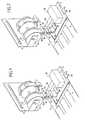
- FIG. 10illustrates a last alternative embodiment of the franking machine corresponding to data entry postage in microcircuit 32C of a label "linerless to transponder "delivered by the second delivery roller 34 and intended to be automatically pasted on a mail item, for example a envelope E.
- a mail itemfor example a envelope E.
Landscapes
- Engineering & Computer Science (AREA)
- Physics & Mathematics (AREA)
- General Physics & Mathematics (AREA)
- Computer Hardware Design (AREA)
- Microelectronics & Electronic Packaging (AREA)
- Theoretical Computer Science (AREA)
- Computer Security & Cryptography (AREA)
- Labeling Devices (AREA)
- Devices For Checking Fares Or Tickets At Control Points (AREA)
Abstract
Translated fromFrenchDescription
Translated fromFrenchLa présente invention se rapporte exclusivement au domaine dutraitement de courrier et elle concerne plus particulièrement une machine àaffranchir du type à jet d'encre pouvant imprimer indistinctement articles decourrier et étiquettes.The present invention relates exclusively to the field ofmail processing and it relates more particularly to apostage of inkjet type can indiscriminately print articles ofmail and labels.
Les machines à affranchir du type à jet d'encre sont bien connues del'homme de l'art. Elles permettent l'affranchissement d'articles de courrierde différents types (enveloppes, encarts, etc.) comme celui d'étiquettes àhumidifier et à coller ensuite sur ces articles ou séparément.Ink jet type postage meters are well known fromone skilled in the art. They allow the franking of mail itemsof different types (envelopes, inserts, etc.) such as that ofmoisten and then stick to these items or separately.
On connaít également depuis déjà quelques années les rubans dits« linerless » qui sont disponibles en rouleaux déroulants notamment pour ladistribution de timbres à la demande (voir par exemple le brevet US 5 663227).We also know for a few years the so-called ribbons"Linerless" which are available in rollers especially for thedistribution of stamps on demand (see for example US patent 5,663227).
Mais, encore à ce jour personne n'a même songé à ce que cettedernière technique pouvait apporter au domaine du traitement de courrier etplus particulièrement aux machines à affranchir.But, to this day no one has even thought about thislatest technique could bring to the field of mail processing andmore particularly to franking machines.
La présente invention a pour but de proposer une nouvellearchitecture de machine à affranchir basée sur l'utilisation de cettetechnique « linerless ». Un but supplémentaire de l'invention est d'accroítrela sécurité des données d'affranchissement portées sur l'article de courrieret d'en faciliter la lecture par l'administration postale.The object of the present invention is to propose a newfranking machine architecture based on the use of this"linerless" technique. An additional object of the invention is to increasethe security of postage data carried on the mail itemand to facilitate reading by the postal administration.
Ces buts sont atteints par une machine pour l'affranchissementd'articles de courrier ou d'étiquettes comprenant une base et un moduled'affranchissement relié à cette base, la base comportant des premiersmoyens de transport pour convoyer les articles de courrier le long d'unchemin de transport d'articles de courrier, depuis une entrée d'articles decourrier vers ledit module d'affranchissement, et des seconds moyens detransport pour convoyer les étiquettes le long d'un chemin de transport desétiquettes, depuis des moyens distributeur d'étiquettes vers ledit moduled'affranchissement, caractérisée en ce que lesdits moyens distributeurcomportent au moins un premier rouleau débitant pour la fourniture enbande d'étiquettes autocollantes de type « linerless ».These goals are achieved by a machine for postagemail items or labels comprising a base and a modulefranking connected to this base, the base comprising firstmeans of transport for conveying mail items along amail item transport path, from a mail item entrymail to said franking module, and second means oftransport to convey the labels along a transport path forlabels, from label dispensing means to said modulefranking, characterized in that said dispensing meanshave at least one first flow roller for supplyingstrip of self-adhesive linerless labels.
Cette nouvelle architecture de machine à affranchir utilisant desrubans autocollants s'avère particulièrement intéressante du fait qu'elleévite la présence d'eau au sein de la machine, c'est à dire qu'elle évite laprésence d'eau dans un environnement électrique.This new architecture of postage meter usingself-adhesive tapes is particularly interesting because itavoids the presence of water inside the machine, i.e. it avoids thepresence of water in an electrical environment.
Les moyens distributeur comportent en outre un second rouleaudébitant pour la fourniture en bande d'étiquettes autocollantes de type« linerless » pourvues de transpondeurs. Ils sont mobiles en translationperpendiculairement aux chemins de transport des articles de courrier et desétiquettes de manière à définir au moins trois positions d'affranchissement.De même, le module d'affranchissement est mobile en translationperpendiculairement au chemin de transport des articles de courrier demanière à définir au moins deux positions d'affranchissement.The dispensing means further comprise a second rollercharge for the supply of self-adhesive type labels"Linerless" provided with transponders. They are mobile in translationperpendicular to the transport routes of mail items andlabels so as to define at least three postage positions.Similarly, the franking module is movable in translationperpendicular to the transport path of mail items fromso as to define at least two postage positions.
Selon un mode de réalisation avantageux, le moduled'affranchissement comporte en outre une troisième positiond'affranchissement pour l'impression de données postales ou non autres queles données d'affranchissement. Ce module d'affranchissement peutcomporter de préférence à la fois un module d'impression à jet d'encre et unmodule d'écriture sans contact.According to an advantageous embodiment, the modulepostage further includes a third positionpostage for printing postal or non-postal data other thanpostage data. This franking module canpreferably include both an inkjet printing module and acontactless writing module.
De préférence, la bande d'étiquettes autocollantes est entraínée pardeux paires de galets amont et aval entre lesquels est disposé un dispositifde coupe du type à ciseaux de sectionnement destiné à sectionner une bandetendue à une longueur déterminée par un dispositif détecteur. Les galetsdisposés du côté d'une face extérieure de la bande sont motorisés, les deuxautres galets faisant fonction de galets presseurs et disposés du côté d'uneface intérieure de la bande étant montés fous et recouverts d'une matièrepeu adhérente pour éviter un collage de la bande d'étiquettes sur ces galets.Preferably, the strip of self-adhesive labels is driven bytwo pairs of upstream and downstream rollers between which is arranged a devicesectioning scissor cutting unit for cutting a stripstretched to a length determined by a detector device. The pebblesarranged on the side of an outer face of the strip are motorized, bothother rollers acting as pressure rollers and arranged on the side of ainside face of the strip being mounted insane and covered with a materialnot very adherent to avoid sticking of the label strip on these rollers.
La machine à affranchir comporte en outre, disposés successivementen sortie desdits galets aval, un coin de guidage courbe pour incurver letrajet de la bande et un autre galet presseur pour appliquer la bande contrelesdits moyens de transport des étiquettes ou contre lesdits articles decourrier supportés par lesdits moyens de transport des articles de courrier.Pour éviter un collage de la bande d'étiquettes, le coin de guidage courbe etlesdits moyens de transport des étiquettes sont recouverts d'un matériau nonadhérent.The franking machine further comprises, arranged successivelyat the outlet of said downstream rollers, a curved guide wedge for curving thestrip path and another pressure roller for applying the strip againstsaid means of transporting the labels or against said articles ofmail supported by said means of transport of mail items.To avoid sticking of the label strip, the curved guide corner andsaid means of transporting the labels are covered with a material notmember.
D'autres caractéristiques et avantages de la présente inventionressortiront mieux de la description suivante, faite à titre indicatif et nonlimitatif, en regard des dessins annexés, sur lesquels:
- la figure 1 est une vue partielle d'une machine à affranchir selonl'invention dans une première position d'impression d'une étiquette,
- la figure 2 est une vue partielle d'une machine à affranchir selonl'invention dans une deuxième position d'impression d'une étiquette,
- la figure 3 est une vue partielle d'une machine à affranchir selonl'invention dans une troisième position d'impression d'une étiquette,
- la figure 4 est une vue partielle d'une machine à affranchir selonl'invention dans une quatrième position d'impression d'une étiquette,
- la figure 5 est une vue partielle d'une machine à affranchir selonl'invention dans une première position d'écriture d'une étiquette,
- la figure 6 est une vue partielle d'une machine à affranchir selonl'invention dans une seconde position d'écriture d'une étiquette,
- la figure 7 est une vue partielle d'une machine à affranchir selonl'invention dans une première position d'impression d'une enveloppe,
- la figure 8 est une vue partielle d'une machine à affranchir selonl'invention dans une deuxième position d'impression d'une enveloppe,
- la figure 9 est une vue partielle d'une machine à affranchir selonl'invention dans une troisième position d'impression d'une enveloppe, et
- la figure 10 est une vue partielle d'une machine à affranchir selonl'invention dans une première position d'écriture d'une enveloppe.
- FIG. 1 is a partial view of a franking machine according to the invention in a first position for printing a label,
- FIG. 2 is a partial view of a franking machine according to the invention in a second position for printing a label,
- FIG. 3 is a partial view of a franking machine according to the invention in a third position for printing a label,
- FIG. 4 is a partial view of a franking machine according to the invention in a fourth position for printing a label,
- FIG. 5 is a partial view of a franking machine according to the invention in a first position for writing a label,
- FIG. 6 is a partial view of a franking machine according to the invention in a second position for writing a label,
- FIG. 7 is a partial view of a franking machine according to the invention in a first position for printing an envelope,
- FIG. 8 is a partial view of a franking machine according to the invention in a second position for printing an envelope,
- FIG. 9 is a partial view of a franking machine according to the invention in a third position for printing an envelope, and
- Figure 10 is a partial view of a franking machine according to the invention in a first writing position of an envelope.
Classiquement une machine à affranchir est formée d'une base etd'un module d'affranchissement relié à cette base. La base comporte desmoyens de transport (rouleaux ou courroie) pour convoyer les articles decourrier au travers de la machine depuis une entrée d'article de courrier lelong d'un chemin de transport des articles de courrier, des moyens decomptabilisation des affranchissements effectués (compteurs ascendant etdescendant notamment), des moyens d'entrée de données et de typesd'affranchissement (au travers d'une interface utilisateur par exemple), etéventuellement des moyens de recharge d'un crédit d'affranchissement (partéléchargement ou module spécifique). De façon facultative, la base peutaussi comporter un dispositif de distribution et de transport d'étiquettes autravers de la machine. Le chemin de transport des étiquettes peut correspondre en partie ou non au chemin de transport des articles decourrier. Le module d'affranchissement comporte de préférence plusieurstêtes d'affranchissement (comportant dans la technologie à jet d'encrechacune une ou plusieurs rangées de buses d'éjection selon les dimensions àimprimer) et au moins des moyens mémoire pour emmagasiner notammentdes paramètres de fonctionnement de ces têtes. Bien entendu, d'autrestechnologies d'impression sont envisageables (report d'encre, transfertthermique...), avec éventuellement un ensemble principal d'impressionassocié à un ensemble secondaire d'impression. Le moduled'affranchissement peut être de type conventionnel (donc rechargeableauprès de l'administration postale) ou de type jetable et relié alors à la basepar une liaison de type sécurisée.Conventionally a franking machine is formed of a base anda franking module connected to this base. The base hasmeans of transport (rollers or belt) to convey the articles ofmail through the machine from a mail item entry onalong a path for transporting mail items, means ofaccounting of postage made (counters ascending anddescendant in particular), means of data entry and typespostage (through a user interface for example), andpossibly means of recharging a postage credit (bydownload or specific module). Optionally, the base canalso include a device for distributing and transporting labels to theacross the machine. The label transport path canpartly or not correspond to the transport path of the articles ofmail. The franking module preferably comprises severalfranking heads (comprising in inkjet technologyeach one or more rows of ejection nozzles according to the dimensions toprint) and at least memory means for storing in particularoperating parameters of these heads. Of course, othersprinting technologies are possible (ink transfer, transferthermal ...), possibly with a main printing unitassociated with a secondary printing unit. The modulefranking can be of conventional type (therefore refillablewith the postal administration) or disposable type and then connected to the baseby a secure type link.
La figure 1 représente de façon schématique et très partielle (limitéeà la zone d'impression) une machine à affranchir selon l'invention. Onreconnaít la base 2 avec ses moyens 4, 6 de transport des articles de courrieret des étiquettes. Ces étiquettes sont délivrées par un distributeurd'étiquettes 8 solidaire de la base. Un module d'affranchissement constituéd'un module d'impression à jet d'encre 10 est bien entendu également prévupour imprimer les données d'affranchissement (empreinte postale) sur lesétiquettes ou les articles de courrier. Ce module d'impression peut aussiservir à l'impression sur les articles de courrier de toutes les autres donnéespostales ou non postales nécessaires à l'expédition (adresse de distribution),la valorisation (message d'avertissement ou publicitaire quelconque parexemple), le tri (code à barres), le suivi (nature du transporteur) et lecontrôle de ces articles. Le module d'alimentation en articles de courrier etles moyens de commande générale de la machine qui sont bien connus del'homme de l'art ne seront pas décrits ni représentés bien quenécessairement présents.Figure 1 shows schematically and very partially (limitedto the printing area) a franking machine according to the invention. Werecognizes
Selon l'invention, cette machine à affranchir est pourvue d'undistributeur d'étiquettes autocollantes (linerless type), c'est à dired'étiquettes dépourvues d'un film siliconé de décollement. Ces étiquettes 12qui comportent une face intérieure adhésive 12A et une face extérieure nonadhésive 12B peuvent être débitées en bande, continue ou prédécoupée,depuis un premier rouleau débitant 14, la face adhésive étant destinée à êtrecollée automatiquement ou manuellement (cas des colis postaux parexemple) sur l'article de courrier à expédier et la face non adhésive étantdestinée à être directement imprimée par la tête d'impression 10. Bien entendu, cette face non adhésive 12B doit être compatible avec uneimpression jet d'encre.According to the invention, this franking machine is provided with adistributor of self-adhesive labels (linerless type), i.e.labels without a silicone release film. These
La bande d'étiquettes « linerless » est entraínée par deux paires degalets amont 16, 18 et aval 20, 22 entre lesquels est disposé un dispositif decoupe 24 du type à ciseaux de sectionnement. Le dispositif de coupe estpositionné entre les deux paires de galets pour pouvoir sectionner une bandetendue à une longueur bien déterminée et contrôlée de façonconventionnelle par un dispositif détecteur (non représenté) comme uncodeur ou un capteur de position mécanique ou optique monté par exemplesur le rouleau 14.The linerless label strip is driven by two pairs of
Les galets 16, 20 disposés du côté de la face extérieure de la bandesont motorisés et commandés par un moteur (non représenté), les deuxautres galets 18, 22 faisant fonction de galets presseurs et disposés du cotéde la face intérieure de la bande étant montés fous et recouverts d'unematière peu adhérente (film de silicone ou de Téflon® par exemple) pouréviter un collage de la bande sur ces galets. En sortie des galets, sontdisposés successivement un coin de guidage courbe 26 pour incurver letrajet de la bande et un autre galet presseur 28 destiné ensuite à appliquer labande sur la courroie sans fin 6 motorisée également par le moteur.The
Comme les premier et deuxième galets presseurs 18, 22, le coin deguidage courbe 26 et la courroie sans fin 6 sont recouverts d'un matériaunon adhérent. L'ensemble de ces éléments est bien entendu monté dans labase et fixé à celle-ci de façon connue en soi et qu'il n'est dès lors pasnécessaire de décrire.Like the first and
Les figures 2 à 4 illustrent le fonctionnement de la machine àaffranchir selon l'invention lors de l'impression d'étiquettes destinées à êtreappliquées manuellement sur des colis postaux.Figures 2 to 4 illustrate the operation of thefranking according to the invention when printing labels intended to beapplied manually to postal parcels.
Sur la figure 2, la bande d'étiquettes « linerless » 12 a été dérouléedu rouleau débitant 14 sur une longueur déterminée correspondant ausectionnement souhaité. On note que le coin de guidage courbe 26 incurvela bande vers le troisième galet presseur 28 qui va l'appliquer contre lacourroie sans fin 6. Le mouvement continu de la courroie sans fin associé àl'action de ce galet presseur va maintenir l'étiquette sectionnée contre lacourroie avec une adhérence suffisante pour permettre ensuite uneimpression de qualité au niveau du module d'impression 10 (voir la figure3). Cette impression est réalisée à la volée, c'est-à-dire sans arrêt de lacourroie 6. Une fois l'impression réalisée, l'étiquette est amenée, dans laposition de la figure 4 où l'utilisateur peut la saisir pour la coller ensuite sur le colis postal auquel elle est destinée (cette saisie étant facilitée d'une partpar un support de préhension 30 solidaire de la base et d'autre part par lefonctionnement en roue libre de la courroie dans cette position de saisie).In FIG. 2, the strip of “linerless” labels 12 has been unrolledof the
La figure 5 illustre un second mode de réalisation de la machine àaffranchir selon l'invention dans lequel le distributeur d'étiquettes 8, montémobile en translation sur la base 2, comporte un second rouleau débitant 34permettant de dérouler des étiquettes autocollantes à transpondeur 32. Detelles étiquettes « linerless » spéciales sont connues du brevet US 6 019865. Elles comportent une face intérieure adhésive 32A et une faceextérieure non adhésive 32B. Elles sont débitées en bande continue, la faceadhésive étant destinée à être collée automatiquement ou manuellement (casdes colis postaux par exemple) sur l'article de courrier à expédier. Entre lesdeux faces de cette étiquette 32 est monté un microcircuit électronique àmémoire 32C appelé « transpondeur » et qui est destiné à recevoir au moinsles données d'affranchissement habituellement présentes sur l'empreintepostale de l'article de courrier à expédier.Figure 5 illustrates a second embodiment of thefranking according to the invention in which the
Comme pour le mode de réalisation précédent, la bande d'étiquettesautocollantes est entraínée par deux paires de galets amont et aval entrelesquels est disposé un dispositif de coupe du type à ciseaux desectionnement. Avantageusement, le dispositif de coupe 24 et les galets aval20, 22 sont ceux utilisés avec le premier rouleau débitant 14, des galetsamont 36, 38 mobiles en translation avec le distributeur étant disposés justeen sortie du rouleau débitant 34. De même, comme précédemment, en sortiede ces deux paires de galets, sont disposés successivement le coin deguidage courbe 26 pour incurver le trajet de la bande et le troisième galetpresseur 28.As for the previous embodiment, the label stripself-adhesive is driven by two pairs of rollers upstream and downstream betweenwhich is arranged a cutting device of the scissor typesectioning. Advantageously, the cutting
La position d'affranchissement de ce second mode de réalisation estillustrée à la figure 6. Il s'agit ici d'une position d'écriture dans letranspondeur 32C. Cette inscription dans la mémoire (de type RAM ouEEPROM) du microcircuit électronique est effectuée à distance (sanscontact) au travers d'un module d'écriture 40 en lieu et place du moduled'impression 10 précité. Cette inscription sans contact est aussi effectuée« au vol ». De préférence, bien entendu, et comme illustré, ces deuxmodules d'impression et d'écriture peuvent cohabiter cote à cote dans lazone d'impression. Une fois la procédure d'écriture dans le microcircuit (etéventuellement de lecture associée) achevée, l'étiquette est avancée sur lesupport de préhension 30 pour être saisie par l'utilisateur.The postage position of this second embodiment isillustrated in figure 6. This is a writing position in the32C transponder. This entry in memory (RAM type orEEPROM) of the electronic microcircuit is carried out remotely (withoutcontact) through a
Ces procédures d'impression ou d'écriture sur une étiquette« linerless » avec ou sans transpondeur peuvent bien entendu aussis'appliquer automatiquement sur un article de courrier. Les figures 7 à 9 et10 respectivement illustrent ces deux variantes de réalisation.These procedures for printing or writing on a label"Linerless" with or without transponder can of course alsoautomatically apply to a mail item. Figures 7 to 9 and10 respectively illustrate these two alternative embodiments.
Sur la figure 7, des étiquettes « linerless » sont déroulées du premierrouleau débitant 14 et sont guidées vers un article de courrier, par exempleune enveloppe E, par les deux paires de galets amont 16, 18 et aval 20, 22entre lesquels est disposé le dispositif de coupe du type à ciseaux desectionnement 24. Pour cela, le dispositif de coupe et les galets aval sontrendus mobiles en translation perpendiculairement au déplacement del'enveloppe de façon à venir occuper une position adéquate par rapport àcette enveloppe.In Figure 7, "linerless" labels are unrolled from the
Dans la position de la figure 8, le rouleau a été débité d'une longueurdéterminée et l'enveloppe s'est avancée d'une distance correspondante pourrecevoir l'extrémité avant de cette étiquette qui se retrouve alorsdirectement collée sur l'enveloppe par le troisième rouleau presseur 28 (etsans aucun apport d'eau par des moyens mouilleur quelconque). On sedispense de la présence d'un dispositif de mouillage, ce qui constitue unavantage déterminant pour des raisons techniques et économiques. Sur lafigure 9, l'étiquette en position sous le module d'impression 10 (qui aurapréalablement fait l'objet d'un déplacement en translation de sa positioninitiale d'impression d'étiquettes) a été sectionnée et est maintenantentièrement collée sur l'enveloppe qui est lors prête à être dirigée vers unmodule externe à la machine à affranchir, par exemple un module destockage.In the position of Figure 8, the roll has been cut to a lengthdetermined and the envelope has advanced a corresponding distance forreceive the front end of this label which is then founddirectly glued to the envelope by the third pressure roller 28 (andwithout any water supply by any wetting means). We areexemption from the presence of a wetting device, which constitutes adecisive advantage for technical and economic reasons. On theFIG. 9, the label in position under the printing module 10 (which willpreviously moved in translation from its positionlabel printing) has been severed and is nowfully glued to the envelope which is then ready to be sent to amodule external to the franking machine, for example a mailing modulestorage.
La figure 10 illustre une dernière variante de réalisation de lamachine à affranchir correspondant à l'inscription de donnéesd'affranchissement dans le microcircuit 32C d'une étiquette « linerless àtranspondeur » débitée par le second rouleau débitant 34 et destinée à êtrecollée automatiquement sur un article de courrier, par exemple uneenveloppe E. Par rapport à la configuration précédente, on notera lenouveau déplacement transversal du distributeur 6 pour amener le secondrouleau débitant 34 sur le chemin de transport des articles de courrier.FIG. 10 illustrates a last alternative embodiment of thefranking machine corresponding to data entrypostage in
Ainsi, le distributeur peut occuper trois positions distinctestransversalement à la direction de déplacement des articles de courrier luipermettant d'assurer les quatre fonctionnalités précédentes
- dans une première position (figure 1), il permet seulementl'impression d'étiquettes « linerless » seules,
- dans une seconde position, il permet soit l'inscription sur desétiquettes « linerless » pourvues de transpondeur (figure 5) soit l'impressiond'étiquettes « linerless » collées sur des articles de courrier (figure 7),
- dans une troisième position (figure 10), il permet l'inscription surdes étiquettes « linerless » pourvues de transpondeur et collées sur desarticles de courrier.
- in a first position (FIG. 1), it only allows the printing of "linerless" labels alone,
- in a second position, it allows either the inscription on “linerless” labels provided with a transponder (FIG. 5) or the printing of “linerless” labels affixed to mail items (FIG. 7),
- in a third position (Figure 10), it allows the inscription on "linerless" labels provided with transponder and glued on mail items.
Avec cette polyvalence dans la distribution des étiquettes, la machineà affranchir de l'invention peut effectuer des affranchissements dedifférentes manières :
- en imprimant conventionnellement des empreintes postalescontenant toutes les données d'information envisageables,
- en produisant des étiquettes imprimées contenant diversesinformations d'affranchissement, et prêtes à être collées manuellement surdes colis ou des grosses enveloppes,
- en produisant des étiquettes semblables aux précédentes maiséquipées d'un transpondeur dans lequel sont enregistrées toutes les donnéesd'affranchissement et également prêtes à l'emploi,
- en collant automatiquement l'un ou l'autre de ces deux typesd'étiquettes « linerless » sur les enveloppes avant la phased'affranchissement (impression ou inscription).
- by conventionally printing postal imprints containing all possible information data,
- by producing printed labels containing various postage information, and ready to be manually stuck on packages or large envelopes,
- by producing labels similar to the previous ones but equipped with a transponder in which all the postage data are stored and also ready for use,
- by automatically sticking one or the other of these two types of “linerless” labels on the envelopes before the franking phase (printing or writing).
Claims (10)
Translated fromFrenchApplications Claiming Priority (2)
| Application Number | Priority Date | Filing Date | Title |
|---|---|---|---|
| FR0012408AFR2814839B1 (en) | 2000-09-29 | 2000-09-29 | MULTIPURPOSE POSTAGE MACHINE |
| FR0012408 | 2000-09-29 |
Publications (2)
| Publication Number | Publication Date |
|---|---|
| EP1193655A1true EP1193655A1 (en) | 2002-04-03 |
| EP1193655B1 EP1193655B1 (en) | 2007-07-25 |
Family
ID=8854816
Family Applications (1)
| Application Number | Title | Priority Date | Filing Date |
|---|---|---|---|
| EP01402464AExpired - LifetimeEP1193655B1 (en) | 2000-09-29 | 2001-09-26 | Multi-purpose franking machine |
Country Status (4)
| Country | Link |
|---|---|
| US (1) | US6579021B2 (en) |
| EP (1) | EP1193655B1 (en) |
| DE (1) | DE60129516T2 (en) |
| FR (1) | FR2814839B1 (en) |
Families Citing this family (10)
| Publication number | Priority date | Publication date | Assignee | Title |
|---|---|---|---|---|
| US7387458B2 (en) | 2003-08-13 | 2008-06-17 | Paxar Americas, Inc. | Printer and method of printing with a plurality of selectable registration sensors |
| CA2575891A1 (en)* | 2004-08-27 | 2006-03-30 | Mark J. Grimes | System including integrated rfid programmer |
| FR2896448A1 (en)* | 2006-01-23 | 2007-07-27 | Neopost Technologies Sa | QUICK PRINT POSTAGE MACHINE |
| US7775732B2 (en)* | 2006-11-30 | 2010-08-17 | International Business Machines Corporation | Multi-roll paper supply for printer |
| US7703998B2 (en)* | 2006-11-30 | 2010-04-27 | Avery Dennison Retail Information Services Llc | Mounting assembly for printer |
| DE102007058765A1 (en)* | 2007-12-06 | 2009-06-25 | Pago Ag, Grabs | Labeling machine for linerless labels |
| WO2011034618A1 (en)* | 2009-09-18 | 2011-03-24 | Goss International Americas, Inc. | A multi-functional maintenance friendly pitch-changing apparatus |
| DE102012200826A1 (en)* | 2011-12-29 | 2013-07-04 | Krones Ag | Labeling unit for e.g. dose bottle, has cut labels transferred individually by gripper cylinder onto containers for labeling either outside of unit main structure or only in unit main structure using hot-setting adhesive |
| BR102015006211A2 (en)* | 2015-03-19 | 2016-10-18 | Giuseppe Jeffrey Arippol | self-adhesive label for non-tape and shielded variable data marking and shielding process and self-adhesive label for non-tape and shielding variable data marking |
| RU2670266C1 (en)* | 2017-06-06 | 2018-10-19 | Александр Иванович Слабинский | Device for detachable connection of long elements |
Citations (8)
| Publication number | Priority date | Publication date | Assignee | Title |
|---|---|---|---|---|
| GB2275668A (en)* | 1993-01-25 | 1994-09-07 | Gananth Wimalal Ediriwira | Data carrying articles such as stamps |
| FR2713804A1 (en)* | 1993-12-08 | 1995-06-16 | Neopost Ind | Automatic distribution of self-adhesive non-precut post franking labels |
| EP0718799A2 (en)* | 1994-12-22 | 1996-06-26 | Pitney Bowes Inc. | Mailing machine utilizing ink jet printer |
| US5663227A (en) | 1996-03-14 | 1997-09-02 | United States Postal Service | Release agent for linerless pressure sensitive postage stamps |
| EP0855683A1 (en)* | 1997-01-24 | 1998-07-29 | Neopost Industrie | Compact mailing machine with special transport path |
| EP0961235A2 (en)* | 1998-05-06 | 1999-12-01 | Pitney Bowes Inc. | Tape storing and feeding mechanism for mailing machines |
| US6019865A (en) | 1998-01-21 | 2000-02-01 | Moore U.S.A. Inc. | Method of forming labels containing transponders |
| EP0996084A2 (en)* | 1998-10-22 | 2000-04-26 | MOBA-Mobile Automation GmbH | Apparatus for printing on a medium |
Family Cites Families (7)
| Publication number | Priority date | Publication date | Assignee | Title |
|---|---|---|---|---|
| US4494127A (en)* | 1982-09-13 | 1985-01-15 | Sci Systems, Inc. | Apparatus and method for recording both machine-readable and printed information |
| US4957179A (en)* | 1987-12-17 | 1990-09-18 | Pitney Bowes Inc. | Tape module for a modular mailing machine |
| US5540369A (en)* | 1993-12-07 | 1996-07-30 | Moore Business Forms, Inc. | Detaching linerless labels |
| US5848810A (en)* | 1995-12-04 | 1998-12-15 | Moore Business Forms, Inc. | Printed labels for postal indicia |
| US5889535A (en)* | 1996-09-23 | 1999-03-30 | Pitney Bowes Inc. | Postage meter including an inkjet printer which has an ink-jet maintenance head translating transverse to the movement of the inkjet print head |
| US5954438A (en)* | 1997-10-30 | 1999-09-21 | Bdt Products, Inc. | Sheet presenter and method of using same |
| ATE202428T1 (en)* | 1999-01-23 | 2001-07-15 | Ident Gmbh X | RFID TRANSPONDER WITH PRINTABLE SURFACE |
- 2000
- 2000-09-29FRFR0012408Apatent/FR2814839B1/ennot_activeExpired - Fee Related
- 2001
- 2001-09-17USUS09/953,196patent/US6579021B2/ennot_activeExpired - Fee Related
- 2001-09-26DEDE60129516Tpatent/DE60129516T2/ennot_activeExpired - Lifetime
- 2001-09-26EPEP01402464Apatent/EP1193655B1/ennot_activeExpired - Lifetime
Patent Citations (8)
| Publication number | Priority date | Publication date | Assignee | Title |
|---|---|---|---|---|
| GB2275668A (en)* | 1993-01-25 | 1994-09-07 | Gananth Wimalal Ediriwira | Data carrying articles such as stamps |
| FR2713804A1 (en)* | 1993-12-08 | 1995-06-16 | Neopost Ind | Automatic distribution of self-adhesive non-precut post franking labels |
| EP0718799A2 (en)* | 1994-12-22 | 1996-06-26 | Pitney Bowes Inc. | Mailing machine utilizing ink jet printer |
| US5663227A (en) | 1996-03-14 | 1997-09-02 | United States Postal Service | Release agent for linerless pressure sensitive postage stamps |
| EP0855683A1 (en)* | 1997-01-24 | 1998-07-29 | Neopost Industrie | Compact mailing machine with special transport path |
| US6019865A (en) | 1998-01-21 | 2000-02-01 | Moore U.S.A. Inc. | Method of forming labels containing transponders |
| EP0961235A2 (en)* | 1998-05-06 | 1999-12-01 | Pitney Bowes Inc. | Tape storing and feeding mechanism for mailing machines |
| EP0996084A2 (en)* | 1998-10-22 | 2000-04-26 | MOBA-Mobile Automation GmbH | Apparatus for printing on a medium |
Also Published As
| Publication number | Publication date |
|---|---|
| US6579021B2 (en) | 2003-06-17 |
| EP1193655B1 (en) | 2007-07-25 |
| DE60129516D1 (en) | 2007-09-06 |
| DE60129516T2 (en) | 2008-04-17 |
| FR2814839B1 (en) | 2003-02-28 |
| US20020039510A1 (en) | 2002-04-04 |
| FR2814839A1 (en) | 2002-04-05 |
Similar Documents
| Publication | Publication Date | Title |
|---|---|---|
| ES2281185T3 (en) | TICKET DISPENSER MECHANISM. | |
| CA2298350C (en) | Process for feeding a labelling unit and label holder | |
| EP1193655B1 (en) | Multi-purpose franking machine | |
| EP0903699B1 (en) | System for preparing mail pieces | |
| EP0191678A1 (en) | Device for processing documents, in particular cheques | |
| FR2626397A1 (en) | METHOD AND DEVICE FOR PRINTING LUGGAGE LABELS, PARTICULARLY FOR AIR TRANSPORT AND LABELS OBTAINED | |
| CH677340A5 (en) | ||
| EP0902929B1 (en) | Device for delivering tickets formed by strip sections | |
| CA2695392C (en) | System for depositing documents into boxes | |
| EP1560165B1 (en) | System to treat post items on the fly | |
| EP1569173B1 (en) | Franking machine with secure external printing mode | |
| EP1676798A1 (en) | Device for making available an imprinted ticket | |
| FR2602354A1 (en) | MULTIPLE DEVICE FOR THE PROCESSING OF CARTONS, IN PARTICULAR OF MAGNETIC TRACK TRANSPORTATION TITLES | |
| EP1814087B1 (en) | Optimised transport device for mail-handling machine | |
| EP0855683A1 (en) | Compact mailing machine with special transport path | |
| EP2187357B1 (en) | Down-market franking machine | |
| EP1293936A1 (en) | Modular and universal system for treating mail | |
| EP0984399B1 (en) | Method for thermal printing | |
| FR2613511A1 (en) | PAYMENT AUTOMATE ISSUING A JUSTIFICATION | |
| FR2612489A3 (en) | PORTABLE ELECTRICAL LABELER | |
| FR2921744A1 (en) | Mail article e.g. envelope, mailing machine, has printing module arranged downstream of supplying module to print transponder on mail article, and read/write head integrated in controlling module to register postal data in transponder | |
| EP0292931B1 (en) | Guiding device for web-like articles | |
| FR2632607A1 (en) | DEVICE FOR DEPOSITING A LABEL ON A FACE OF A BOX | |
| US20110047101A1 (en) | Internet Digital Mail System Printer | |
| EP1811463A2 (en) | Quick-printing franking machine |
Legal Events
| Date | Code | Title | Description |
|---|---|---|---|
| PUAI | Public reference made under article 153(3) epc to a published international application that has entered the european phase | Free format text:ORIGINAL CODE: 0009012 | |
| AK | Designated contracting states | Kind code of ref document:A1 Designated state(s):DE FR GB Kind code of ref document:A1 Designated state(s):AT BE CH CY DE DK ES FI FR GB GR IE IT LI LU MC NL PT SE TR | |
| AX | Request for extension of the european patent | Free format text:AL;LT;LV;MK;RO;SI | |
| 17P | Request for examination filed | Effective date:20020927 | |
| AKX | Designation fees paid | Free format text:DE FR GB | |
| RAP1 | Party data changed (applicant data changed or rights of an application transferred) | Owner name:NEOPOST TECHNOLOGIES | |
| 17Q | First examination report despatched | Effective date:20060621 | |
| GRAP | Despatch of communication of intention to grant a patent | Free format text:ORIGINAL CODE: EPIDOSNIGR1 | |
| GRAS | Grant fee paid | Free format text:ORIGINAL CODE: EPIDOSNIGR3 | |
| GRAA | (expected) grant | Free format text:ORIGINAL CODE: 0009210 | |
| AK | Designated contracting states | Kind code of ref document:B1 Designated state(s):DE FR GB | |
| REG | Reference to a national code | Ref country code:GB Ref legal event code:FG4D Free format text:NOT ENGLISH | |
| RIN1 | Information on inventor provided before grant (corrected) | Inventor name:DESHAYES, XAVIER Inventor name:PAUL, ARSENE | |
| REF | Corresponds to: | Ref document number:60129516 Country of ref document:DE Date of ref document:20070906 Kind code of ref document:P | |
| GBT | Gb: translation of ep patent filed (gb section 77(6)(a)/1977) | Effective date:20071003 | |
| PLBE | No opposition filed within time limit | Free format text:ORIGINAL CODE: 0009261 | |
| STAA | Information on the status of an ep patent application or granted ep patent | Free format text:STATUS: NO OPPOSITION FILED WITHIN TIME LIMIT | |
| 26N | No opposition filed | Effective date:20080428 | |
| PGFP | Annual fee paid to national office [announced via postgrant information from national office to epo] | Ref country code:GB Payment date:20120920 Year of fee payment:12 | |
| PGFP | Annual fee paid to national office [announced via postgrant information from national office to epo] | Ref country code:DE Payment date:20120921 Year of fee payment:12 | |
| PGFP | Annual fee paid to national office [announced via postgrant information from national office to epo] | Ref country code:FR Payment date:20121010 Year of fee payment:12 | |
| GBPC | Gb: european patent ceased through non-payment of renewal fee | Effective date:20130926 | |
| REG | Reference to a national code | Ref country code:FR Ref legal event code:ST Effective date:20140530 | |
| REG | Reference to a national code | Ref country code:DE Ref legal event code:R119 Ref document number:60129516 Country of ref document:DE Effective date:20140401 | |
| PG25 | Lapsed in a contracting state [announced via postgrant information from national office to epo] | Ref country code:GB Free format text:LAPSE BECAUSE OF NON-PAYMENT OF DUE FEES Effective date:20130926 | |
| PG25 | Lapsed in a contracting state [announced via postgrant information from national office to epo] | Ref country code:DE Free format text:LAPSE BECAUSE OF NON-PAYMENT OF DUE FEES Effective date:20140401 Ref country code:FR Free format text:LAPSE BECAUSE OF NON-PAYMENT OF DUE FEES Effective date:20130930 |