EP1192905A1 - Surgical retractor - Google Patents
Surgical retractorDownload PDFInfo
- Publication number
- EP1192905A1 EP1192905A1EP01121134AEP01121134AEP1192905A1EP 1192905 A1EP1192905 A1EP 1192905A1EP 01121134 AEP01121134 AEP 01121134AEP 01121134 AEP01121134 AEP 01121134AEP 1192905 A1EP1192905 A1EP 1192905A1
- Authority
- EP
- European Patent Office
- Prior art keywords
- holder
- retractor blades
- guide
- access channel
- instrument
- Prior art date
- Legal status (The legal status is an assumption and is not a legal conclusion. Google has not performed a legal analysis and makes no representation as to the accuracy of the status listed.)
- Granted
Links
- 238000006073displacement reactionMethods0.000claimsdescription12
- 230000006835compressionEffects0.000description7
- 238000007906compressionMethods0.000description7
- 238000003780insertionMethods0.000description3
- 230000037431insertionEffects0.000description3
- 241001631457CannulaSpecies0.000description1
- 238000010276constructionMethods0.000description1
- 238000007654immersionMethods0.000description1
- 230000008676importEffects0.000description1
- 238000007373indentationMethods0.000description1
- 230000000149penetrating effectEffects0.000description1
- 238000012216screeningMethods0.000description1
- 230000007704transitionEffects0.000description1
Images


Classifications
- A—HUMAN NECESSITIES
- A61—MEDICAL OR VETERINARY SCIENCE; HYGIENE
- A61B—DIAGNOSIS; SURGERY; IDENTIFICATION
- A61B17/00—Surgical instruments, devices or methods
- A61B17/02—Surgical instruments, devices or methods for holding wounds open, e.g. retractors; Tractors
- A61B17/0206—Surgical instruments, devices or methods for holding wounds open, e.g. retractors; Tractors with antagonistic arms as supports for retractor elements
- A—HUMAN NECESSITIES
- A61—MEDICAL OR VETERINARY SCIENCE; HYGIENE
- A61B—DIAGNOSIS; SURGERY; IDENTIFICATION
- A61B17/00—Surgical instruments, devices or methods
- A61B17/34—Trocars; Puncturing needles
- A61B17/3417—Details of tips or shafts, e.g. grooves, expandable, bendable; Multiple coaxial sliding cannulas, e.g. for dilating
- A61B17/3421—Cannulas
- A61B17/3439—Cannulas with means for changing the inner diameter of the cannula, e.g. expandable
- A—HUMAN NECESSITIES
- A61—MEDICAL OR VETERINARY SCIENCE; HYGIENE
- A61B—DIAGNOSIS; SURGERY; IDENTIFICATION
- A61B90/00—Instruments, implements or accessories specially adapted for surgery or diagnosis and not covered by any of the groups A61B1/00 - A61B50/00, e.g. for luxation treatment or for protecting wound edges
- A61B90/50—Supports for surgical instruments, e.g. articulated arms
Definitions
- the inventionrelates to a device for creating a percutaneous Access into a body with two together forming an access channel, each have a proximal and a distal end Retractor blades, the distance between them changing the Cross section of the access channel is changeable.
- a guideis arranged at the proximal end thereof which is a holder for an instrument having a tubular shaft slidably mounted in a plane arranged transversely to the access channel is that an instrument held on the holder with its tubular shaft at various points in the cross section of the access channel in submerged this.
- a guideis therefore arranged on a retractor blade, the one Allows displacement of the holder in a plane that is transverse to Longitudinal direction of the access channel, and this enables the Displacement of the tubular shaft immersed in the access channel.
- both retractor bladeseach have one have such a guide for a holder.
- the guidesare parallel to the contour of the retractor blades run. Then it is possible by moving the holder along these guides the tubular shaft along the retractor blades move, for example directly on the wall of the retractor blade along.
- the guides of the two retractor blades with the retractor blades maximally approximatedsurround the access channel in a ring. That’s it once possible, the bracket on the two guides in any position to arrange along the retractor blade, on the other hand at retractor sheets approaching each other, the holder from the guide one retractor blade on the guide of the other retractor blade be pushed.
- the guide or the guidesrun in a circular arc.
- the guide or the guidescan for example be in the proximal Direction ledges protruding from the retractor blades his.
- the holderhas a fixing device by means of which it is releasably fixable relative to the guide.
- the fixing devicecan be a clamping device.
- the guide and the holdercooperate Wear locking elements through which the holder is gridded is slidable along the guide.
- the surgeonhas the Possibility to move the holder rastered along the guide and the position determined provisionally by the grid, a final one
- the fixing devicefor example a Clamping device.
- the locking elementscan be indentations and elastically engaging in them Be a step ahead.
- the holdercarries a bracket for the instrument, which is relative to the holder in Direction to the center of the access channel is displaceable.
- a bracket for the instrumentwhich is relative to the holder in Direction to the center of the access channel is displaceable.
- the holdercan be arranged on a carriage, for example, which is slidably mounted on a guide of the holder.
- Bracket and bracketcan be made by elastically interacting Locking elements can be shifted against each other.
- a clamping devicecan be attached to the holder for releasable fixation of the instrument be arranged on the holder so that the angular position of the Instrument and / or the immersion depth of the instrument relative to Holder can be set.
- this tensioning devicehas the invention two side by side the tubular shaft of the instrument surrounding holding members on in a transverse to the longitudinal axis of the Tube shaft extending plane are mutually displaceable. As a result, the tubular shaft is moved when these holding members are moved pressed on one side against one of the holding members and in the press fit kept between them.
- the retractor bladescan have an arcuate cross section be and run into lateral edge areas that are parallel to their displacement when changing the mutual distance and overlap when the retractor blades are approaching. That’s it possible, even with a larger distance between the retractor blades To create an access channel that is surrounded on all sides by the retractor blades and is closed with it.
- the retractor bladesare on movable against each other and thereby the distance between the retractor blades mutually changing support elements held.
- thesecan be two holding arms, which can be pivoted together are connected and at their free ends a retractor blade wear.
- These support elementscan in turn on a stationary frame structure be definable.
- the retractor bladescan be detachably held on the support elements so that it is possible to use retractor blades suitable for the special operation to attach to the support elements, for example a set of retractor blades of different lengths can be used from which the surgeon inserted the retractor blade when inserting the device with the correct length. It is also possible to use the retractor blades to replace on the support elements, for example when changing the direction of operation.
- Any instrumentscan be held on the holder have a tubular shaft-shaped part which plunges into the access channel, in particular, such an instrument can be an endoscope.
- the device 1 shown in the drawing to create a percutaneous access into a bodycomprises two holding arms 2, 3 which at one end by a bearing screw 4 pivotable with each other are connected.
- the holding arms 2 and 3are approximately at a distance from bent a third of its length from the storage location by about 30 °, so that through the holding arms 2, 3 in the area of the bearing screw 4 spanned plane opposite the plane that holds the holding arms Clamp 2, 3 in the area of their free ends 5, 6, inclined by 30 ° is.
- the holding arms 2, 3are by means of a rod 10 on one in the drawing only fixed frame structure 11 indicated by dash-dotted lines and can be permanently positioned in this way that their free ends 5, 6 over the intended surgical area can be arranged.
- Both free ends 5, 6 of the holding arms 2, 3point outwards open, cross-sectionally U-shaped receiving opening 12 or 13 with one along the entire side wall of the receiving opening 12, 13 running, central projecting retaining ribs 14 and 15.
- each holding armthere is a through hole 16 which in Area of the holding ribs 14, 15 opens into the receiving opening 12, 13, namely in the straight part of the U-shaped receiving opening 12, 13 closely adjacent to the adjacent arcuate Part of the receiving opening 12, 13.
- this through hole 16is a protruding from this receiving opening 12, 13
- Pressure body 17mounted longitudinally on which one in the Receiving hole 12, 13 arranged compression spring 18, which is on the other side on a screwed into the receiving opening 12, 13 Support screw 19 supports.
- the pressure body 17is thus can be inserted and inserted elastically into the receiving opening 12, 13 by the compression spring 18 from the through hole 16 into the receiving opening 12, 13 advanced, the pressure body 17th prevented by a stop 20 from the through hole 16 to exit completely.
- the receiving openings 12, 13serve to receive two retractor blades 21, 22, by means of holding pins 23 in these receiving openings 12, 13 can be used.
- This holding pin 23, the two Retractor blades 21 and 22are identical, have one Diameter that corresponds to the width of the receiving openings 12, 13 and have a circumferential groove 24 into which the lateral insertion the holding pin 23 in the receiving openings 12, 13, the holding ribs 14, 15 occur.
- the retaining pins 23are fully inserted these are in the receiving openings 12, 13 by the pressure body 17 set, which abut the outer wall of the holding pin 23 and insert them into the receiving openings 12, 13 (FIG. 6).
- the compression spring 18By pressing the compression spring 18, however, the retaining pin can 23 again pulled out of the receiving openings 12, 13 the operator needs a certain amount of force, so that an unintentional escape of the holding pin 23 from the receiving openings 12, 13 is prevented.
- the holding pins 23are each connected to a connecting part 25 parallel to the holding pin 23 from the connecting part 25 downwards protruding retaining element 26 connected, which consists of a semicircular curved wall, which is slightly at its lower end converges.
- the two retaining elements 26are in the inserted state to the opposite retaining element 26 open and together with this form an access channel 27 out.
- Both retaining elements 26end in edge areas 28 and 29, which run parallel to each other and also parallel to move the receiving openings 12, 13 when opening and closing the holding arms 2, 3 by turning the bearing screw 4.
- the edge areas 28 and 29overlap, see above that when increasing the distance between the two retaining elements 26 the access channel 27 they enclosed via a larger one The area remains closed on all sides (FIGS. 4 to 6).
- Each of the two holding pins 23carries on its the connecting part 25 opposite top end a substantially semicircular Guide 30, 31, which is a horizontal, flange-like base part 32 and a strip-shaped guide part projecting vertically upwards 33 includes.
- the guides 30 and 31are designed so that with maximally approximated retractor blades 21 and 22 the Guide parts 33 form a substantially closed ring, which surrounds the access channel 27 at a distance.
- the guide parts 33are concentric with the retaining elements 26, have a larger radius and are like that Retaining elements 26 open towards each other.
- a holder 34has a lower part 35 with an open at the bottom Guide groove 36 formed according to the guide part 33 and which accommodates the guide part 33 when the holder 34 with the lower part 35 from above onto the guide part 33 of a retractor blade 21, 22 is placed.
- Lower part 35can be moved along the guide part 33, and Appropriate means are provided to support the holder 34 in various ways Determine positions along the guide member 33.
- Permanent fixationcan be achieved by a screw spindle 43, the radial between the two through holes 37 and 38 Direction is screwed into the lower part 35 and with its free end 44 can dip into a recess 42 of the guide part 33.
- the Screw 43is rotatable by means of a handle 45 and can Holder 34 permanently in a certain position along the guide part 33 establish.
- the lower part 35When the screw 43 is loosened, the lower part 35 can be moved along the Guide part 33 move rasterized and can be approximated Retractor blades 21, 22 also on the guide part 33 of the adjacent one Re Thermalorblattes be pushed when the guide parts 33rd are arranged exactly in a ring to each other. Otherwise it is possible, the lower part 35 after loosening the screw spindle 43 upwards deduct and attach to the other guide part 33 from above.
- the displacement movementis also rasterized, namely by an elastic locking element, which in a recess of the lower part 35 occurs.
- This screeningcan be done in the same way can be achieved, as in the case of displacement of the lower part 35 lengthways of the guide part 33, that is by means of a pressure piece which with a Compression spring is tensioned against a recess in the lower part, this is schematically indicated in FIG. 7 by reference numeral 48.
- the holder 47has a receiving sleeve 49, the longitudinal axis runs parallel to the longitudinal axis of the access channel 27 and as a receptacle for a tubular shaft 50 of a surgical instrument 51 serves, in the illustrated embodiment of Figure 1 of an endoscope.
- a sleeve-shaped clamping element 53Arranged in a direction transverse to the longitudinal direction of the receiving sleeve 49 and the receiving sleeve 49 penetrating slot 52 of the Bracket 47 is a sleeve-shaped clamping element 53 parallel to the direction of displacement the bracket 47 slidably on the lower part 35 mounted in this clamping element 53, a clamping screw 54 is parallel screwed to this direction of movement, which via a handle 55 can be twisted.
- the clamping screw 54is in a bore 56 the holder 47 rotatable and axially immovable by a pin 37 stored so that when the clamping screw 54 is turned Clamping element 53 parallel to the direction of displacement of the holder 47 in the same can be moved.
- the tensioning element 53has an opening 58 in the form of a Elongated hole, the longitudinal axis of which is parallel to the direction of displacement of the Clamping element 53 extends and the width of the inner diameter corresponds to the receiving sleeve 49.
- This opening 58covers the interior of the receiving sleeve 49 so that a through the receiving sleeve 49 pushed tubular shaft 50 the opening 58 of the Clamping element 53 penetrates. If you move the clamping element 53 by means of the clamping screw 54, the clamping element is thereby clamped 53 and places the tubular shaft against the wall of the receiving sleeve 49 thereby the tubular shaft in the receiving sleeve 49 against rotation and axial displacement fixed. This clamp connection is by loosening the Clamping screw 54 can be released at any time.
- a body accessis, for example, one in the body inserted wire and over one or more concentrically above it pushed sleeves opened, and over such a sleeve the two retaining elements 56 inserted into the interior of the body, they form a slid over the tube inserted into the body Tube out and laterally displace the body tissue.
- After removal of the wire inserted first and the wire inserted first Tubestherefore define the two retaining elements 26 as tubular Access to the interior of the body, the size of which is pivoted the holding arm can be enlarged, it is sufficient to operate the adjusting screw 7.
- the access channel 27goes when enlarging from a circular cross-section into an im essential oval cross section.
- the holder 34 on one of the Guides 30 or 31placed from above and by displacement pivoted along the guide members 33 into the desired angular position.
- the desired instrument 51is then with the tubular shaft 50 inserted through the receiving sleeve 49 until the desired Insertion depth is reached.
- This positioncan be determined using the Tension screw 54 can be set if the position of the tubular shaft 50 in the cross section of the access channel 27 can still be changed is, this is done by moving the holder 34 along the guide member 33 and by moving the holder 47 relative to the lower part 35 possible.
- the Screw 53tightened so that another shift along the guide part 33 is no longer possible.
- tubular shaft 50can at any point of the Cross section of the access channel 27 can be positioned, and it is This position is also possible in the simplest possible way adapt and change.
- the instrumentcan be disassembled in the simplest possible way it suffices to loosen the clamping screw 54 and the screw spindle 43, then the parts can be clearly seen in FIG Separate and clean separately. In particular it is It is also possible to replace entire retractor blades if desired becomes.
- the cross section of the access channel 27may be the whole Operation changed at any time by turning the adjusting screw 27 be, this is also possible if an instrument 51 is in the access channel 27 is inserted.
- the diameter of the tubular shaft 50can, for example, be of the order of 7 mm, the In contrast, the diameter of the retaining elements 26 is of the order of magnitude of 15 mm, so that the cross-sectional area of the tubular shaft 50 is considerably smaller than the cross-sectional area of the access channel 27.
Landscapes
- Health & Medical Sciences (AREA)
- Life Sciences & Earth Sciences (AREA)
- Surgery (AREA)
- Molecular Biology (AREA)
- General Health & Medical Sciences (AREA)
- Biomedical Technology (AREA)
- Heart & Thoracic Surgery (AREA)
- Medical Informatics (AREA)
- Nuclear Medicine, Radiotherapy & Molecular Imaging (AREA)
- Animal Behavior & Ethology (AREA)
- Engineering & Computer Science (AREA)
- Public Health (AREA)
- Veterinary Medicine (AREA)
- Surgical Instruments (AREA)
- Dental Preparations (AREA)
- Materials For Medical Uses (AREA)
- Saccharide Compounds (AREA)
Abstract
Description
Translated fromGermanDie Erfindung betrifft eine Vorrichtung zur Schaffung eines perkutanenZugangs in einen Körper mit zwei gemeinsam einen Zugangskanal bildenden,jeweils ein proximales und ein distales Ende aufweisendenRetraktorblättern, deren Abstand voneinander unter Veränderung desQuerschnitts des Zugangskanals veränderbar ist.The invention relates to a device for creating a percutaneousAccess into a body with two together forming an access channel,each have a proximal and a distal endRetractor blades, the distance between them changing theCross section of the access channel is changeable.
Zur Schaffung eines perkutanen Zugangs, wie er beispielsweise beieiner lumbalen Diskektomie benötigt wird, ist es bekannt, in den Körperrohrförmige Kanülen einzusetzen und an diesen mittels eines Positioniertellersoder mittels einer Positionierhülse zusätzliche Instrumenteso anzuordnen, daß ein rohrschaftförmiges Teil dieser Instrumente imRandbereich des Querschnitts des Zugangskanals in diesen eintaucht(DE 198 25 763 A1; WO 97/34 537). Es ist dadurch möglich, denRohrschaft des eintauchenden Instrumentes, beispielsweise den Rohrschafteines Endoskops, längs des Randes des Zugangskanals in unterschiedlichenPositionen anzuordnen, wobei neben dem Rohrschaft nochein Teil des Querschnitts des Zugangskanals frei bleibt für die Einfuhrweiterer Instrumente. Voraussetzung für eine solche Konstruktion istjedoch eine rohrförmige Ausbildung des Zugangskanals, da nur dannein Positionierteller oder eine Positionierhülse verdrehbar an dem Zugangskanalgelagert werden können.To create a percutaneous access, such as inIf a lumbar discectomy is needed, it is known in the bodyinsert tubular cannulas and on them by means of a positioning plateor additional instruments using a positioning sleeveto be arranged so that a tubular part of these instruments in theEdge area of the cross section of the access channel is immersed in this(DE 198 25 763 A1; WO 97/34 537). This makes it possible toTube shaft of the immersing instrument, for example the tube shaftof an endoscope, along the edge of the access channel in differentArrange positions, being next to the tubular shaftpart of the cross-section of the access channel remains free for importother instruments. The prerequisite for such a construction ishowever, a tubular design of the access channel, since only thena positioning plate or a positioning sleeve rotatable on the access channelcan be stored.
Andererseits ist es auch bekannt, zur Schaffung eines perkutanen Zugangszwei gemeinsam den Zugangskanal bildende Retraktorblätter zuverwenden, die in ihrem Abstand so veränderbar sind, daß dadurch derQuerschnitt des Zugangskanals veränderbar ist. Eine Lagerung von zusätzlichen Instrumenten über einen Positionierteller oder eine Positionierhülseist bei diesen gegeneinander bewegbaren Retraktorblätternnicht möglich.On the other hand, it is also known to create percutaneous accesstwo retractor blades together forming the access channeluse, which are so variable in their distance that theCross section of the access channel is changeable. Storage of additionalInstruments via a positioning plate or a positioning sleeveis in these mutually movable retractor bladesnot possible.
Es ist Aufgabe der Erfindung, eine gattungsgemäße Vorrichtung zurSchaffung eines perkutanen Zugangs so auszubilden, daß auch bei gegeneinanderbewegbaren Retraktorblättern der Rohrschaft eines Instrumentesan unterschiedlichen Positionen des Zugangskanals angeordnetwerden kann.It is an object of the invention to provide a generic device forCreation of a percutaneous access to train so that also against each othermovable retractor blades of the tubular shaft of an instrumentarranged at different positions of the access channelcan be.
Diese Aufgabe wird bei einer Vorrichtung der eingangs beschriebenenArt erfindungsgemäß dadurch gelöst, daß zumindest an einem Retraktorblattan dessen proximalem Ende eine Führung angeordnet ist, aufder ein Halter für ein einen Rohrschaft aufweisendes Instrument derartin einer quer zum Zugangskanal angeordneten Ebene verschiebbar gelagertist, daß ein am Halter gehaltenes Instrument mit seinem Rohrschaftan verschiedener Stelle des Querschnitts des Zugangskanals indiesen eintaucht.This object is achieved in a device as described in the introductionArt solved according to the invention in that at least on a retractor bladea guide is arranged at the proximal end thereofwhich is a holder for an instrument having a tubular shaftslidably mounted in a plane arranged transversely to the access channelis that an instrument held on the holder with its tubular shaftat various points in the cross section of the access channel insubmerged this.
Es wird also an einem Retraktorblatt eine Führung angeordnet, die eineVerschiebung des Halters in einer Ebene ermöglicht, die quer zurLängsrichtung des Zugangskanals verläuft, und dies ermöglicht dieVerschiebung des in den Zugangskanal eintauchenden Rohrschaftes.A guide is therefore arranged on a retractor blade, the oneAllows displacement of the holder in a plane that is transverse toLongitudinal direction of the access channel, and this enables theDisplacement of the tubular shaft immersed in the access channel.
Besonders vorteilhaft ist es, wenn beide Retraktorblätter jeweils einederartige Führung für einen Halter aufweisen.It is particularly advantageous if both retractor blades each have onehave such a guide for a holder.
Günstig ist es, wenn die Führungen parallel zur Kontur der Retraktorblätterverlaufen. Dann ist es möglich, durch Verschiebung des Halterslängs dieser Führungen den Rohrschaft längs den Retraktorblättern zubewegen, beispielsweise unmittelbar an der Wand des Retraktorblattesentlang.It is advantageous if the guides are parallel to the contour of the retractor bladesrun. Then it is possible by moving the holderalong these guides the tubular shaft along the retractor bladesmove, for example directly on the wall of the retractor bladealong.
Bei einer bevorzugten Ausführungsform ist vorgesehen, daß die Führungender beiden Retraktorblätter bei maximal angenäherten Retraktorblätternden Zugangskanal ringförmig umgeben. Dadurch ist eseinmal möglich, die Halterung auf den beiden Führungen in jeder Positionlängs des Retraktorblattes anzuordnen, zum anderen kann beieinander angenäherten Retraktorblättern die Halterung von der Führungeines Retraktorblattes auf die Führung des anderen Retraktorblattesgeschoben werden.In a preferred embodiment it is provided that the guidesof the two retractor blades with the retractor blades maximally approximatedsurround the access channel in a ring. That’s itonce possible, the bracket on the two guides in any positionto arrange along the retractor blade, on the other hand atretractor sheets approaching each other, the holder from the guideone retractor blade on the guide of the other retractor bladebe pushed.
Insbesondere verlaufen die Führung bzw. die Führungen kreisbogenförmig.In particular, the guide or the guides run in a circular arc.
Die Führung bzw. die Führungen können beispielsweise als in proximalerRichtung von den Retraktorblättern abstehende Leisten ausgebildetsein.The guide or the guides can for example be in the proximalDirection ledges protruding from the retractor bladeshis.
Günstig ist es, wenn der Halter eine Fixiereinrichtung aufweist, mittelsder er relativ zu der Führung lösbar fixierbar ist.It is expedient if the holder has a fixing device by means ofwhich it is releasably fixable relative to the guide.
Insbesondere kann die Fixiereinrichtung eine Klemmeinrichtung sein.In particular, the fixing device can be a clamping device.
Es ist weiterhin vorteilhaft, wenn die Führung und der Halter zusammenwirkendeRastelemente tragen, durch die der Halter gerastertlängs der Führung verschiebbar ist. Der Operateur hat dadurch dieMöglichkeit, den Halter längs der Führung gerastert zu verschieben unddie Position durch die Rasterung vorläufig festzulegen, eine endgültigeFestlegung erfolgt durch die Fixiereinrichtung, beispielsweise eineKlemmeinrichtung.It is also advantageous if the guide and the holder cooperateWear locking elements through which the holder is griddedis slidable along the guide. The surgeon has thePossibility to move the holder rastered along the guide andthe position determined provisionally by the grid, a final oneThe fixing device, for example aClamping device.
Die Rastelemente können Vertiefungen und elastisch in diese eingreifendeVorsprünge sein.The locking elements can be indentations and elastically engaging in themBe a step ahead.
Bei einer bevorzugten Ausführungsform ist vorgesehen, daß der Haltereine Halterung für das Instrument trägt, die relativ zum Halter inRichtung auf den Mittelpunkt des Zugangskanals verschiebbar ist. Dadurchkann zusätzlich die Position des Rohrschaftes im Inneren desZugangsquerschnittes in Bezug auf den Mittelpunkt des Zugangskanalesverändert werden, insgesamt ermöglichen diese Ausgestaltungenalso, den Rohrschaft an beliebiger Stelle des Zugangskanals zu positionieren.In a preferred embodiment it is provided that the holdercarries a bracket for the instrument, which is relative to the holder inDirection to the center of the access channel is displaceable. Therebycan also the position of the tubular shaft inside theAccess cross-section in relation to the center of the access channelbe changed, overall these configurations allowthat is, to position the tubular shaft at any point on the access channel.
Die Halterung kann beispielsweise an einem Schlitten angeordnet sein,der an einer Führung des Halters verschiebbar gelagert ist.The holder can be arranged on a carriage, for example,which is slidably mounted on a guide of the holder.
Auch hier ist es günstig, wenn die Halterung relativ zum Halter in verschiedenenPositionen lösbar fixierbar ist.It is also advantageous here if the holder is different in relation to the holderPositions can be detachably fixed.
Halter und Halterung können durch elastisch zusammenwirkendeRastelemente gerastert gegeneinander verschiebbar sein.Bracket and bracket can be made by elastically interactingLocking elements can be shifted against each other.
Am Halter kann eine Spannvorrichtung zur lösbaren Fixierung des Instrumentesam Halter angeordnet sein, so daß die Winkelstellung desInstrumentes und/oder die Eintauchtiefe des Instrumentes relativ zumHalter festgelegt werden kann.A clamping device can be attached to the holder for releasable fixation of the instrumentbe arranged on the holder so that the angular position of theInstrument and / or the immersion depth of the instrument relative toHolder can be set.
Diese Spannvorrichtung weist bei einer bevorzugten Ausführungsformder Erfindung zwei nebeneinander den Rohrschaft des Instrumentesumgebende Halteglieder auf, die in einer quer zur Längsachse desRohrschaftes verlaufenden Ebene gegeneinander verschiebbar sind.Dadurch wird der Rohrschaft beim Verschieben dieser Halteglieder jeweilseinseitig gegen eines der Halteglieder gepreßt und im Klemmsitzzwischen ihnen gehalten.In a preferred embodiment, this tensioning device hasthe invention two side by side the tubular shaft of the instrumentsurrounding holding members on in a transverse to the longitudinal axis of theTube shaft extending plane are mutually displaceable.As a result, the tubular shaft is moved when these holding members are movedpressed on one side against one of the holding members and in the press fitkept between them.
Die Retraktorblätter können im Querschnitt bogenförmig ausgebildetsein und in seitliche Randbereiche auslaufen, die parallel zu ihrer Verschiebungbeim Verändern des gegenseitigen Abstands verlaufen undsich bei angenäherten Retraktorblättern überdecken. Dadurch ist esmöglich, auch bei einem größeren Abstand der Retraktorblätter einenZugangskanal zu schaffen, der allseits von den Retraktorblättern umgebenund damit geschlossen ist.The retractor blades can have an arcuate cross sectionbe and run into lateral edge areas that are parallel to their displacementwhen changing the mutual distance andoverlap when the retractor blades are approaching. That’s itpossible, even with a larger distance between the retractor bladesTo create an access channel that is surrounded on all sides by the retractor bladesand is closed with it.
Bei einer bevorzugten Ausführungsform werden die Retraktorblätter angegeneinander bewegbaren und dadurch den Abstand der Retraktorblättervoneinander verändernden Tragelementen gehalten.In a preferred embodiment, the retractor blades are onmovable against each other and thereby the distance between the retractor bladesmutually changing support elements held.
Diese können insbesondere zwei Haltearme sein, die schwenkbar miteinanderverbunden sind und an ihren freien Enden jeweils ein Retraktorblatttragen.In particular, these can be two holding arms, which can be pivoted togetherare connected and at their free ends a retractor bladewear.
Diese Tragelemente können ihrerseits an einer ortsfesten Rahmenstrukturfestlegbar sein.These support elements can in turn on a stationary frame structurebe definable.
Es ist vorteilhaft, wenn die Tragelemente durch eine Feststellvorrichtungin festem Abstand zueinander fixierbar sind.It is advantageous if the support elements by a locking devicecan be fixed at a fixed distance from each other.
Die Retraktorblätter können an den Tragelementen lösbar gehaltensein, so daß es möglich ist, für die spezielle Operation geeignete Retraktorblätteran den Tragelementen zu befestigen, beispielsweise kannein Satz von unterschiedlich langen Retraktorblättern verwendet werden,aus dem der Chirurg beim Einsetzen der Vorrichtung das Retraktorblattmit der richtigen Länge auswählt. Es ist auch möglich, die Retraktorblätteran den Tragelementen auszutauschen, beispielsweisebeim Ändern der Operationsrichtung.The retractor blades can be detachably held on the support elementsso that it is possible to use retractor blades suitable for the special operationto attach to the support elements, for examplea set of retractor blades of different lengths can be usedfrom which the surgeon inserted the retractor blade when inserting the devicewith the correct length. It is also possible to use the retractor bladesto replace on the support elements, for examplewhen changing the direction of operation.
Um diese Lösbarkeit zu erreichen, kann es beispielsweise vorgesehensein, daß zur lösbaren Festlegung der Retraktorblätter an den Tragelementenzusammenwirkende elastische Rastelemente vorgesehensind.In order to achieve this solvability, it can be provided, for examplebe that for releasable fixing of the retractor blades on the support elementscooperating elastic locking elements providedare.
Am Halter können beliebige Instrumente gehalten werden, die einrohrschaftförmiges, in den Zugangskanal eintauchendes Teil aufweisen,insbesondere kann ein solches Instrument ein Endoskop sein.Any instruments can be held on the holderhave a tubular shaft-shaped part which plunges into the access channel,in particular, such an instrument can be an endoscope.
Die nachfolgende Beschreibung bevorzugter Ausführungsformen derErfindung dient im Zusammenhang mit der Zeichnung der näheren Erläuterung.Es zeigen:
- Figur 1:
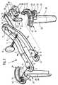
- eine perspektivische Ansicht einer zwei Retraktorblätteraufweisenden Vorrichtung zur Schaffung eines perkutanenZugangs mit einem in einen Halter eingesetztenEndoskop;
- Figur 2:
- eine perspektivische Ansicht der Vorrichtung der
Figur 1ohne Endoskop und mit voneinander getrennten Einzelteilen; - Figur 3:
- eine Seitenansicht der Vorrichtung der
Figur 1 ohne Endoskop; - Figur 4:
- eine Schnittansicht längs Linie 4-4 in
Figur 3; - Figur 5:
- eine Schnittansicht längs Linie 5-5 in
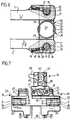
Figur 3; - Figur 6:
- eine Schnittansicht längs Linie 6-6 in
Figur 3 und - Figur 7:
- eine Teilansicht der Vorrichtung der
Figur 3 in Richtungdes Pfeiles A.
- Figure 1:
- a perspective view of a device having two retractor blades for creating a percutaneous access with an endoscope inserted into a holder;
- Figure 2:
- a perspective view of the device of Figure 1 without endoscope and with separate parts;
- Figure 3:
- a side view of the device of Figure 1 without endoscope;
- Figure 4:
- a sectional view taken along line 4-4 in Figure 3;
- Figure 5:
- a sectional view taken along line 5-5 in Figure 3;
- Figure 6:
- a sectional view taken along line 6-6 in Figure 3 and
- Figure 7:
- a partial view of the device of Figure 3 in the direction of arrow A.
Die in der Zeichnung dargestellte Vorrichtung 1 zur Schaffung einesperkutanen Zugangs in einen Körper umfaßt zwei Haltearme 2, 3, diean einem Ende durch eine Lagerschraube 4 schwenkbar miteinander verbunden sind. Die Haltearme 2 und 3 sind etwa im Abstand voneinem Drittel ihrer Länge von der Lagerstelle entfernt um etwa 30° abgebogen,so daß die durch die Haltearme 2, 3 im Bereich der Lagerschraube4 aufgespannte Ebene gegenüber der Ebene, die die Haltearme2, 3 im Bereich ihrer freien Enden 5, 6 aufspannen, um 30° geneigtist. Im Übergangsbereich der beiden Ebenen ist eine in einemHaltearm 2 frei verdrehbar und axial unverschieblich gelagerte Verstellschraube7 angeordnet, die eine Gewindebohrung 8 in dem anderenHaltearm durchsetzt und die mittels eines Griffes 9 verdrehtwerden kann, so daß dadurch der Öffnungswinkel der beiden Haltearme2, 3 bleibend veränderbar ist.The
Die Haltearme 2, 3 sind mittels einer Stange 10 an einer in der Zeichnungnur strichpunktiert angedeuteten ortsfesten Rahmenstruktur 11festgelegt und können auf diese Weise dauerhaft so positioniert werden,daß ihre freien Enden 5, 6 über dem vorgesehenen Operationsbereichangeordnet werden können.The holding
Beide freie Enden 5, 6 der Haltearme 2, 3 weisen eine nach außen hinoffene, im Querschnitt U-förmige Aufnahmeöffnung 12 bzw. 13 auf miteiner längs der gesamten Seitenwand der Aufnahmeöffnung 12, 13verlaufenden, mittigen vorspringenden Halterippe 14 bzw. 15.Both free ends 5, 6 of the holding
In jedem Haltearm befindet sich eine Durchgangsbohrung 16, die imBereich der Halterippe 14, 15 in die Aufnahmeöffnung 12, 13 einmündet,und zwar im geradlinigen Teil der U-förmigen Aufnahmeöffnung12, 13 dicht benachbart neben dem sich daran anschließenden bogenförmigenTeil der Aufnahmeöffnung 12, 13. In dieser Durchgangsbohrung 16 ist ein aus dieser Aufnahmeöffnung 12, 13 hervorstehenderDruckkörper 17 längsverschieblich gelagert, an dem sich eine in derAufnahmebohrung 12, 13 angeordnete Druckfeder 18 befindet, die sichauf der anderen Seite an einer in die Aufnahmeöffnung 12, 13 eingeschraubtenVerschlußschraube 19 abstützt. Der Druckkörper 17 istsomit elastisch in die Aufnahmeöffnung 12, 13 einschiebbar und wirddurch die Druckfeder 18 aus der Durchgangsbohrung 16 in die Aufnahmeöffnung12, 13 vorgeschoben, dabei wird der Druckkörper 17durch einen Anschlag 20 daran gehindert, aus der Durchgangsbohrung16 vollständig auszutreten.In each holding arm there is a through
Die Aufnahmeöffnungen 12, 13 dienen der Aufnahme von zwei Retraktorblättern21, 22, die mittels Haltezapfen 23 in diese Aufnahmeöffnungen12, 13 einsetzbar sind. Diese Haltezapfen 23, die bei beidenRetraktorblättern 21 und 22 gleich ausgebildet sind, haben einenDurchmesser, der der Breite der Aufnahmeöffnungen 12, 13 entsprichtund weisen eine Umfangsnut 24 auf, in die beim seitlichen Einschiebender Haltezapfen 23 in die Aufnahmeöffnungen 12, 13 die Halterippen14, 15 eintreten. Beim vollständigen Einschieben der Haltezapfen 23werden diese in den Aufnahmeöffnungen 12, 13 durch die Druckkörper17 festgelegt, die sich an die Außenwand der Haltezapfen 23 anlegenund diese in die Aufnahmeöffnungen 12, 13 einschieben (Figur 6).Unter Zusammendrücken der Druckfeder 18 kann jedoch der Haltezapfen23 wieder aus den Aufnahmeöffnungen 12, 13 herausgezogenwerden, dazu benötigt der Operateur einen gewissen Kraftaufwand, sodaß ein unbeabsichtigtes Austreten der Haltezapfen 23 aus den Aufnahmeöffnungen12, 13 verhindert wird.The receiving
Die Haltezapfen 23 sind jeweils über ein Verbindungsteil 25 mit einemparallel zu den Haltezapfen 23 von dem Verbindungsteil 25 nach untenabstehenden Rückhalteelement 26 verbunden, welches aus einer halbkreisförmiggebogenen Wand besteht, die an ihrem unteren Ende geringfügigkonisch zusammenläuft. Die beiden Rückhalteelemente 26sind im eingesetzten Zustand jeweils zum gegenüberliegenden Rückhalteelement26 offen und bilden gemeinsam mit diesem einen Zugangskanal27 aus. Beide Rückhalteelemente 26 enden in Randbereichen28 bzw. 29, die parallel zueinander verlaufen und außerdem parallelzur Verschieberichtung der Aufnahmeöffnungen 12, 13 beim Öffnenund Schließen der Haltearme 2, 3 durch Verdrehen der Lagerschraube4. Die Randbereiche 28 und 29 überdecken sich dabei, sodaß bei der Vergrößerung des Abstandes der beiden Rückhalteelemente26 der von ihnen eingeschlossene Zugangskanal 27 über einen größerenBereich allseits geschlossen bleibt (Figuren 4 bis 6).The holding pins 23 are each connected to a connecting
Jeder der beiden Haltezapfen 23 trägt an seinem dem Verbindungsteil25 gegenüberliegenden oberen Ende eine im wesentlichen halbkreisförmigeFührung 30, 31, die ein horizontales, flanschartiges Basisteil32 und ein senkrecht nach oben abstehendes, leistenförmiges Führungsteil33 umfaßt. Dabei sind die Führungen 30 und 31 so ausgebildet,daß bei maximal angenäherten Retraktorblättern 21 und 22 dieFührungsteile 33 einen im wesentlichen geschlossenen Ring ausbilden,welcher den Zugangskanal 27 im Abstand umgibt.Each of the two holding
Die Führungsteile 33 verlaufen konzentrisch zu den Rückhalteelementen26, weisen einen größeren Radius auf und sind ebenso wie dieRückhalteelemente 26 zueinander hin geöffnet.The
Ein Halter 34 weist ein Unterteil 35 mit einer nach unten hin offenenFührungsnut 36 auf, die entsprechend dem Führungsteil 33 ausgebildetist und die das Führungsteil 33 in sich aufnimmt, wenn der Halter 34mit dem Unterteil 35 von oben her auf das Führungsteil 33 eines Retraktorblattes21, 22 aufgesetzt wird. Ein in dieser Weise aufgesetztesUnterteil 35 kann längs des Führungsteiles 33 verschoben werden, undes sind geeignete Mittel vorgesehen, um den Halter 34 in verschiedenenPositionen längs des Führungsteils 33 festzulegen.A
Dazu sind im Unterteil 35 in Durchgangsbohrungen 37 und 38, die radialvon außen her in die Führungsnut 36 einmünden, Druckstücke 39in Längsrichtung verschiebbar gelagert, die von einer in der Durchgangsbohrung37, 38 angeordneten Druckfeder 40 in Richtung auf dieFührungsnut 36 verschoben werden. Die Druckfeder 40 stützt sich jeweilsan einer Verschlußschraube 41 ab, die in die Durchgangsbohrungen37, 38 eingeschraubt ist, und die Druckstücke 39 tauchen unterder Wirkung der Druckfeder 40 in jeweils eine von mehreren Vertiefungen42 auf der Außenseite des leistenförmigen Führungsteiles 33 ein,die in Umfangsrichtung verteilt sind. Dadurch ergibt sich eine elastischeRasterung bei der Verschiebung des Unterteiles 35 auf dem Führungsteil33, bei Aufbringung einer bestimmten Verschiebekraft kannder Halter 34 gerastert längs des Führungsteiles 33 verschoben werden,wird aber bei einer erreichten Endposition in dieser gehalten.These are in the
Eine dauerhafte Fixierung kann erfolgen durch eine Schraubspindel 43,die zwischen den beiden Durchgangsbohrungen 37 und 38 in radialerRichtung in das Unterteil 35 eingeschraubt ist und mit ihrem freien Ende 44 in eine Vertiefung 42 des Führungsteils 33 eintauchen kann. DieSchraubspindel 43 ist mittels eines Griffes 45 verdrehbar und kann denHalter 34 in einer bestimmten Position längs des Führungsteils 33 dauerhaftfestlegen.Permanent fixation can be achieved by a
Bei gelöster Schraubspindel 43 läßt sich das Unterteil 35 längs desFührungsteils 33 gerastert verschieben und kann bei angenähertenRetraktorblättern 21, 22 auch auf das Führungsteil 33 des benachbartenRetraktorblattes geschoben werden, wenn die Führungsteile 33genau ringförmig zueinander angeordnet sind. Im übrigen ist es auchmöglich, das Unterteil 35 nach Lösen der Schraubspindel 43 nach obenabzuziehen und von oben her auf das andere Führungsteil 33 aufzustecken.When the
Am Unterteil 35 des Halters 34 ist auf einer radial zum Führungsteil 33angeordneten Führung 46 eine Halterung 47 schlittenartig verschieblichgelagert, deren Verschiebebewegung ebenfalls gerastert erfolgt,und zwar durch ein elastisches Rastelement, welches in eine Ausnehmungdes Unterteils 35 eintritt. Diese Rasterung kann in gleicher Weiseerreicht werden, wie im Falle der Verschiebung des Unterteils 35 längsdes Führungsteils 33, also mittels eines Druckstückes, das mit einerDruckfeder gegen eine Vertiefung des Unterteils gespannt wird, dies istin Figur 7 durch das Bezugszeichen 48 schematisch angedeutet.On the
Die Halterung 47 weist eine Aufnahmehülse 49 auf, deren Längsachseparallel zur Längsachse des Zugangskanals 27 verläuft und die als Aufnahmefür einen Rohrschaft 50 eines chirurgischen Instruments 51dient, im dargestellten Ausführungsbeispiel der Figur 1 eines Endoskops. In einem quer zur Längsrichtung der Aufnahmehülse 49 angeordnetenund die Aufnahmehülse 49 durchsetzenden Schlitz 52 derHalterung 47 ist ein hülsenförmiges Spannelement 53 parallel zur Verschieberichtungder Halterung 47 auf dem Unterteil 35 verschieblichgelagert, in dieses Spannelement 53 ist eine Spannschraube 54 parallelzu dieser Verschieberichtung eingeschraubt, die über ein Griffteil 55verdreht werden kann. Die Spannschraube 54 ist in einer Bohrung 56der Halterung 47 drehbar und durch einen Stift 37 axial unverschiebbargelagert, so daß bei einer Verdrehung der Spannschraube 54 dasSpannelement 53 parallel zur Verschieberichtung der Halterung 47 inderselben verschoben werden kann.The
Das Spannelement 53 weist eine Durchbrechung 58 auf in Form einesLangloches, dessen Längsachse parallel zur Verschieberichtung desSpannelementes 53 verläuft und dessen Breite dem Innendurchmesserder Aufnahmehülse 49 entspricht. Diese Durchbrechung 58 überdecktden Innenraum der Aufnahmehülse 49, so daß ein durch die Aufnahmehülse49 geschobener Rohrschaft 50 die Durchbrechung 58 desSpannelementes 53 durchsetzt. Verschiebt man das Spannelement 53mittels der Spannschraube 54, so spannt dadurch das Spannelement53 den Rohrschaft gegen die Wand der Aufnahmehülse 49 und legtdadurch den Rohrschaft in der Aufnahmehülse 49 gegen Drehung undaxiale Verschiebung fest. Diese Klemmverbindung ist durch Lösen derSpannschraube 54 jederzeit lösbar.The
Bei der Benutzung der beschriebenen Vorrichtung wird diese normalerweisezunächst ohne den Halter 34 und ohne Instrument 51 verwendet.Ein Körperzugang wird beispielsweise über einen in den Körper eingeführten Draht und über eine oder mehrere konzentrisch darübergeschobene Hülsen eröffnet, und über eine solche Hülse werden diebeiden Rückhalteelemente 56 in das Innere des Körpers eingeschoben,sie bilden dabei ein über das in den Körper eingebrachte Rohr geschobenesRohr aus und verdrängen das Körpergewebe seitlich. Nach Entfernungdes zuerst eingesetzten Drahtes und der zuerst eingesetztenRohre definieren die beiden Rückhalteelemente 26 somit einen rohrförmigenZugang in das Innere des Körpers, dessen Größe durch Verschwenkender Haltearme vergrößert werden kann, dazu genügt es,die Verstellschraube 7 zu betätigen. Der Zugangskanal 27 geht dabeibei der Vergrößerung von einem kreisförmigen Querschnitt in einen imwesentlichen ovalen Querschnitt über.When using the described device, this will normallyfirst used without the
Nach diesem Einsetzen der Vorrichtung und der gewünschten Wahl desQuerschnittes des Zugangskanals 27 wird der Halter 34 auf eine derFührungen 30 oder 31 von oben her aufgesetzt und durch Verschiebunglängs der Führungsteile 33 in die gewünschte Winkellage verschwenkt.Das gewünschte Instrument 51 wird dann mit dem Rohrschaft50 durch die Aufnahmehülse 49 eingeschoben, bis die gewünschteEinschubtiefe erreicht ist. Diese Position kann mittels derSpannschraube 54 festgelegt werden, falls die Position des Rohrschaftes50 im Querschnitt des Zugangskanals 27 noch geändert werdensoll, ist dies durch Verschiebung des Halters 34 längs des Führungsteiles33 und durch Verschiebung der Halterung 47 relativ zum Unterteil35 möglich. Bei Erreichen der gewünschten Endposition wird dieSchraubspindel 53 festgezogen, so daß eine weitere Verschiebunglängs des Führungsteils 33 nicht mehr möglich ist.After this insertion of the device and the desired choice ofCross section of the
Auf diese Weise kann der Rohrschaft 50 an jeder beliebigen Stelle desQuerschnitts des Zugangskanals 27 positioniert werden, und es istauch in einfachster Weise möglich, diese Position den jeweiligen Wünschenanzupassen und zu verändern.In this way, the
Eine Zerlegung des Instrumentes ist in einfachster Weise möglich, esgenügt dazu, die Spannschraube 54 und die Schraubspindel 43 zu lösen,dann lassen sich die Teile in der in Figur 2 deutlich sichtbarenWeise voneinander trennen und getrennt reinigen. Insbesondere ist esauch möglich, ganze Retraktorblätter auszutauschen, wenn dies gewünschtwird.The instrument can be disassembled in the simplest possible wayit suffices to loosen the clamping
Der Querschnitt des Zugangskanals 27 kann während der gesamtenOperation jederzeit durch Verdrehen der Verstellschraube 27 geändertwerden, dies ist auch möglich, wenn ein Instrument 51 in den Zugangskanal27 eingesetzt ist.The cross section of the
Durch die variable Verschiebbarkeit des Halters 34 ist insbesonderesichergestellt, daß der Rohrschaft 50 innerhalb des Zugangskanals 27immer an einer Stelle angeordnet werden kann, die einen weiteren Zugangdurch den Zugangskanal 27 zur Operationsstelle ermöglicht unddiesen Zugang nicht behindert. Der Durchmesser des Rohrschaftes 50kann beispielsweise in der Größenordnung von 7 mm liegen, derDurchmesser der Rückhalteelemente 26 dagegen in der Größenordnungvon 15 mm, so daß die Querschnittsfläche des Rohrschaftes 50erheblich kleiner ist als die Querschnittsfläche des Zugangskanals 27.Due to the variable displaceability of the
Claims (24)
Translated fromGermanApplications Claiming Priority (2)
| Application Number | Priority Date | Filing Date | Title |
|---|---|---|---|
| DE10048790 | 2000-10-02 | ||
| DE10048790ADE10048790A1 (en) | 2000-10-02 | 2000-10-02 | Device for creating percutaneous access |
Publications (2)
| Publication Number | Publication Date |
|---|---|
| EP1192905A1true EP1192905A1 (en) | 2002-04-03 |
| EP1192905B1 EP1192905B1 (en) | 2010-11-10 |
Family
ID=7658435
Family Applications (1)
| Application Number | Title | Priority Date | Filing Date |
|---|---|---|---|
| EP01121134AExpired - LifetimeEP1192905B1 (en) | 2000-10-02 | 2001-09-04 | Surgical retractor |
Country Status (3)
| Country | Link |
|---|---|
| EP (1) | EP1192905B1 (en) |
| AT (1) | ATE487425T1 (en) |
| DE (2) | DE10048790A1 (en) |
Cited By (23)
| Publication number | Priority date | Publication date | Assignee | Title |
|---|---|---|---|---|
| WO2004002323A3 (en)* | 2002-06-26 | 2004-03-25 | Sdgi Holdings Inc | Instruments and methods for minimally invasive tissue retraction and surgery |
| US7014608B2 (en) | 2002-12-13 | 2006-03-21 | Synthes Spine Company, Lp | Guided retractor and methods of use |
| US7144368B2 (en) | 2003-11-26 | 2006-12-05 | Synthes Spine Company, Lp | Guided retractor and methods of use |
| US7473222B2 (en) | 2002-06-26 | 2009-01-06 | Warsaw Orthopedic, Inc. | Instruments and methods for minimally invasive tissue retraction and surgery |
| US7491168B2 (en) | 2003-12-18 | 2009-02-17 | Depuy Spine, Inc. | Surgical retractor systems and illuminated cannulae |
| EP1494591A4 (en)* | 2002-04-05 | 2010-05-26 | Boss Instr Ltd | Side loading surgical retractor |
| US7758501B2 (en) | 2006-01-04 | 2010-07-20 | Depuy Spine, Inc. | Surgical reactors and methods of minimally invasive surgery |
| US7867238B2 (en) | 2001-03-01 | 2011-01-11 | Warsaw Orthopedic, Inc. | Method for using dynamic lordotic guard |
| US7892174B2 (en) | 2006-07-19 | 2011-02-22 | Zimmer Spine, Inc. | Surgical access system and method of using the same |
| US7955360B2 (en) | 2001-03-01 | 2011-06-07 | Warsaw Orthopedic, Inc. | Method for using dynamic lordotic guard with movable extensions for creating an implantation space posteriorly in the lumbar spine |
| US7955257B2 (en) | 2006-01-05 | 2011-06-07 | Depuy Spine, Inc. | Non-rigid surgical retractor |
| US7981031B2 (en) | 2006-01-04 | 2011-07-19 | Depuy Spine, Inc. | Surgical access devices and methods of minimally invasive surgery |
| US8100828B2 (en) | 2002-11-23 | 2012-01-24 | George Frey | Distraction and retraction system for spinal surgery |
| US8211012B2 (en) | 2008-09-30 | 2012-07-03 | Aesculap Implant Systems, Llc | Tissue retractor system |
| US8262569B2 (en) | 2006-07-19 | 2012-09-11 | Zimmer Spine, Inc. | Surgical access system and method of using the same |
| EP2810597A1 (en)* | 2013-05-22 | 2014-12-10 | Karl Storz GmbH & Co. KG | Device for providing an access port into a body, in particular for spinal surgery |
| US20150045624A1 (en)* | 2013-08-06 | 2015-02-12 | Minimally Invasive Surgical Access Limited | Intra-Thoracic Access Device Without Thoracotomy, and Related Methods |
| WO2015070499A1 (en)* | 2013-11-12 | 2015-05-21 | 冉旭东 | Retractor |
| EP2939588A3 (en)* | 2014-03-11 | 2016-08-10 | Stryker European Holdings I, LLC | Endoscopic surgical systems and methods |
| WO2016144089A1 (en)* | 2015-03-10 | 2016-09-15 | 주식회사 메드릭스 | Foldable blade type retractor for minimally invasive surgery |
| US9622732B2 (en) | 2004-10-08 | 2017-04-18 | Nuvasive, Inc. | Surgical access system and related methods |
| US10278686B2 (en) | 2010-09-20 | 2019-05-07 | DePuy Synthes Products, Inc. | Spinal access retractor |
| US11793504B2 (en) | 2011-08-19 | 2023-10-24 | Nuvasive, Inc. | Surgical retractor system and methods of use |
Families Citing this family (18)
| Publication number | Priority date | Publication date | Assignee | Title |
|---|---|---|---|---|
| WO2001037728A1 (en) | 1999-11-24 | 2001-05-31 | Nuvasive, Inc. | Electromyography system |
| EP1417000B1 (en) | 2001-07-11 | 2018-07-11 | Nuvasive, Inc. | System for determining nerve proximity during surgery |
| JP2005503857A (en) | 2001-09-25 | 2005-02-10 | ヌバシブ, インコーポレイテッド | Systems and methods for performing surgical procedures and surgical diagnosis |
| US7261688B2 (en) | 2002-04-05 | 2007-08-28 | Warsaw Orthopedic, Inc. | Devices and methods for percutaneous tissue retraction and surgery |
| US7582058B1 (en) | 2002-06-26 | 2009-09-01 | Nuvasive, Inc. | Surgical access system and related methods |
| US8137284B2 (en) | 2002-10-08 | 2012-03-20 | Nuvasive, Inc. | Surgical access system and related methods |
| US7691057B2 (en) | 2003-01-16 | 2010-04-06 | Nuvasive, Inc. | Surgical access system and related methods |
| US7819801B2 (en) | 2003-02-27 | 2010-10-26 | Nuvasive, Inc. | Surgical access system and related methods |
| JP4463819B2 (en) | 2003-09-25 | 2010-05-19 | ヌヴァシヴ インコーポレイテッド | Surgical access system |
| US7905840B2 (en) | 2003-10-17 | 2011-03-15 | Nuvasive, Inc. | Surgical access system and related methods |
| DE102005032197B4 (en)* | 2005-07-09 | 2019-07-04 | Richard Wolf Gmbh | Endoscopic instrument |
| US7918792B2 (en) | 2006-01-04 | 2011-04-05 | Depuy Spine, Inc. | Surgical retractor for use with minimally invasive spinal stabilization systems and methods of minimally invasive surgery |
| US8968192B2 (en) | 2008-06-06 | 2015-03-03 | Warsaw Orthopedic, Inc. | Systems and methods for tissue retraction |
| US8226554B2 (en) | 2008-10-30 | 2012-07-24 | Warsaw Orthopedic, Inc. | Retractor assemblies for surgery in a patient |
| AU2009329873A1 (en) | 2008-12-26 | 2011-11-03 | Scott Spann | Minimally-invasive retroperitoneal lateral approach for spinal surgery |
| US8790406B1 (en) | 2011-04-01 | 2014-07-29 | William D. Smith | Systems and methods for performing spine surgery |
| US8636656B2 (en) | 2011-08-16 | 2014-01-28 | Warsaw Orthopedic, Inc. | Retractor assemblies with blade drive mechanisms |
| US9198765B1 (en) | 2011-10-31 | 2015-12-01 | Nuvasive, Inc. | Expandable spinal fusion implants and related methods |
Citations (10)
| Publication number | Priority date | Publication date | Assignee | Title |
|---|---|---|---|---|
| US4989587A (en)* | 1989-04-26 | 1991-02-05 | Farley Daniel K | Sternal retractor |
| WO1996002195A1 (en)* | 1994-07-19 | 1996-02-01 | Jako Geza J | Retractors, tool, and method for direct access endoscopic surgery |
| WO1997034537A1 (en) | 1996-03-16 | 1997-09-25 | Elke Tashiro | Device for drawing off gases and particles by suction |
| US5697891A (en)* | 1997-01-06 | 1997-12-16 | Vista Medical Technologies, Inc. | Surgical retractor with accessory support |
| WO1998027869A1 (en)* | 1996-12-23 | 1998-07-02 | University Of Massachusetts | Minimally invasive surgical apparatus and method |
| WO1999009892A1 (en)* | 1997-08-27 | 1999-03-04 | Coroneo Inc. | Sternum retractor for stabilizing the beating heart during coronary artery bypass graft surgery |
| WO1999015069A2 (en)* | 1997-09-19 | 1999-04-01 | United States Surgical Corporation | Surgical apparatus and method |
| EP0951868A1 (en)* | 1998-04-27 | 1999-10-27 | Waldemar Link (GmbH & Co.) | Surgical retractor |
| DE19825763A1 (en) | 1998-06-09 | 1999-12-16 | Dieter Von Zeppelin | Endoscope system for spinal surgery |
| DE19844251A1 (en)* | 1998-09-26 | 2000-04-13 | Elmar Willems | Rib expanding and lifting device for use during heart surgery using the MIDCAB method, has toothed rack and gripping unit |
Family Cites Families (13)
| Publication number | Priority date | Publication date | Assignee | Title |
|---|---|---|---|---|
| US1959127A (en)* | 1933-05-04 | 1934-05-15 | Duerme Francisco Maya | Surgical instrument |
| US3021842A (en)* | 1958-11-05 | 1962-02-20 | John F Flood | Hypodermic needle guide |
| DE3319049A1 (en)* | 1982-11-26 | 1984-05-30 | Richard Wolf Gmbh, 7134 Knittlingen | Rectoscope |
| US4547092A (en)* | 1984-02-21 | 1985-10-15 | Hamilton Industries | Accessory clamp for medical table |
| US4809694A (en)* | 1987-05-19 | 1989-03-07 | Ferrara Vincent L | Biopsy guide |
| US4796846A (en)* | 1987-06-01 | 1989-01-10 | Automated Medical Products, Corporation | Retaining device for a surgical instrument |
| US5658272A (en)* | 1992-09-15 | 1997-08-19 | Hasson; Harrith M. | Surgical instrument support and method of using the same |
| US5354302A (en)* | 1992-11-06 | 1994-10-11 | Ko Sung Tao | Medical device and method for facilitating intra-tissue visual observation and manipulation of distensible tissues |
| US5613937A (en)* | 1993-02-22 | 1997-03-25 | Heartport, Inc. | Method of retracting heart tissue in closed-chest heart surgery using endo-scopic retraction |
| DE19780707C2 (en)* | 1996-03-22 | 2002-09-12 | Sdgi Holdings Inc | Percutaneous surgery device |
| US5875782A (en)* | 1996-11-14 | 1999-03-02 | Cardiothoracic Systems, Inc. | Methods and devices for minimally invasive coronary artery revascularization on a beating heart without cardiopulmonary bypass |
| US5836559A (en)* | 1997-05-23 | 1998-11-17 | Ronci; Samuel | Clamp for securing a pole to a stationary object |
| US5951466A (en)* | 1998-04-13 | 1999-09-14 | Viamedics, Llc | Self-seating surgical access device and method of gaining surgical access to a body cavity |
- 2000
- 2000-10-02DEDE10048790Apatent/DE10048790A1/ennot_activeWithdrawn
- 2001
- 2001-09-04ATAT01121134Tpatent/ATE487425T1/enactive
- 2001-09-04EPEP01121134Apatent/EP1192905B1/ennot_activeExpired - Lifetime
- 2001-09-04DEDE50115701Tpatent/DE50115701D1/ennot_activeExpired - Lifetime
Patent Citations (10)
| Publication number | Priority date | Publication date | Assignee | Title |
|---|---|---|---|---|
| US4989587A (en)* | 1989-04-26 | 1991-02-05 | Farley Daniel K | Sternal retractor |
| WO1996002195A1 (en)* | 1994-07-19 | 1996-02-01 | Jako Geza J | Retractors, tool, and method for direct access endoscopic surgery |
| WO1997034537A1 (en) | 1996-03-16 | 1997-09-25 | Elke Tashiro | Device for drawing off gases and particles by suction |
| WO1998027869A1 (en)* | 1996-12-23 | 1998-07-02 | University Of Massachusetts | Minimally invasive surgical apparatus and method |
| US5697891A (en)* | 1997-01-06 | 1997-12-16 | Vista Medical Technologies, Inc. | Surgical retractor with accessory support |
| WO1999009892A1 (en)* | 1997-08-27 | 1999-03-04 | Coroneo Inc. | Sternum retractor for stabilizing the beating heart during coronary artery bypass graft surgery |
| WO1999015069A2 (en)* | 1997-09-19 | 1999-04-01 | United States Surgical Corporation | Surgical apparatus and method |
| EP0951868A1 (en)* | 1998-04-27 | 1999-10-27 | Waldemar Link (GmbH & Co.) | Surgical retractor |
| DE19825763A1 (en) | 1998-06-09 | 1999-12-16 | Dieter Von Zeppelin | Endoscope system for spinal surgery |
| DE19844251A1 (en)* | 1998-09-26 | 2000-04-13 | Elmar Willems | Rib expanding and lifting device for use during heart surgery using the MIDCAB method, has toothed rack and gripping unit |
Cited By (48)
| Publication number | Priority date | Publication date | Assignee | Title |
|---|---|---|---|---|
| US8372079B2 (en) | 2001-03-01 | 2013-02-12 | Warsaw Orthopedic, Inc. | Dynamic guard and method for use thereof |
| US9597202B2 (en) | 2001-03-01 | 2017-03-21 | Warsaw Orthopedic, Inc. | Method for using a guard for creating a socket posteriorly in the spine |
| US8764755B2 (en) | 2001-03-01 | 2014-07-01 | Warsaw Orthopedic, Inc. | Method for using a guard for creating a socket posteriorly in the lumbar spine |
| US7955360B2 (en) | 2001-03-01 | 2011-06-07 | Warsaw Orthopedic, Inc. | Method for using dynamic lordotic guard with movable extensions for creating an implantation space posteriorly in the lumbar spine |
| US7909832B2 (en) | 2001-03-01 | 2011-03-22 | Warsaw Orthopedic, Inc. | Retractor for percutaneous surgery in a patient and method for use thereof |
| US9211198B2 (en) | 2001-03-01 | 2015-12-15 | Warsaw Orthopedic, Inc. | Method for using a guard for creating a socket posteriorly in the lumbar spine |
| US7998143B2 (en) | 2001-03-01 | 2011-08-16 | Warsaw Orthopedic, Inc. | Dynamic guard |
| US7867238B2 (en) | 2001-03-01 | 2011-01-11 | Warsaw Orthopedic, Inc. | Method for using dynamic lordotic guard |
| EP1494591A4 (en)* | 2002-04-05 | 2010-05-26 | Boss Instr Ltd | Side loading surgical retractor |
| EP2289425A3 (en)* | 2002-06-26 | 2014-04-23 | Warsaw Orthopedic, Inc. | Instruments for minimally invasive tissue retraction and surgery |
| US7513869B2 (en) | 2002-06-26 | 2009-04-07 | Warsaw Orthopedic, Inc. | Instruments and methods for minimally invasive tissue retraction and surgery |
| US7524285B2 (en) | 2002-06-26 | 2009-04-28 | Warsaw Orthopedic, Inc. | Instruments and methods for minimally invasive tissue retraction and surgery |
| US6945933B2 (en) | 2002-06-26 | 2005-09-20 | Sdgi Holdings, Inc. | Instruments and methods for minimally invasive tissue retraction and surgery |
| WO2004002323A3 (en)* | 2002-06-26 | 2004-03-25 | Sdgi Holdings Inc | Instruments and methods for minimally invasive tissue retraction and surgery |
| CN100364483C (en)* | 2002-06-26 | 2008-01-30 | 华沙整形外科股份有限公司 | Instruments and methods for minimally invasive tissue retraction and surgery |
| US7473222B2 (en) | 2002-06-26 | 2009-01-06 | Warsaw Orthopedic, Inc. | Instruments and methods for minimally invasive tissue retraction and surgery |
| US8100828B2 (en) | 2002-11-23 | 2012-01-24 | George Frey | Distraction and retraction system for spinal surgery |
| US7014608B2 (en) | 2002-12-13 | 2006-03-21 | Synthes Spine Company, Lp | Guided retractor and methods of use |
| US7144368B2 (en) | 2003-11-26 | 2006-12-05 | Synthes Spine Company, Lp | Guided retractor and methods of use |
| US10869657B2 (en) | 2003-12-18 | 2020-12-22 | DePuy Synthes Products, Inc. | Surgical retractor systems and illuminated cannulae |
| US7491168B2 (en) | 2003-12-18 | 2009-02-17 | Depuy Spine, Inc. | Surgical retractor systems and illuminated cannulae |
| US8602984B2 (en) | 2003-12-18 | 2013-12-10 | DePuy Synthes Products, LLC | Surgical retractor systems and illuminated cannulae |
| US11723644B2 (en) | 2004-10-08 | 2023-08-15 | Nuvasive, Inc. | Surgical access system and related methods |
| US9622732B2 (en) | 2004-10-08 | 2017-04-18 | Nuvasive, Inc. | Surgical access system and related methods |
| US7981031B2 (en) | 2006-01-04 | 2011-07-19 | Depuy Spine, Inc. | Surgical access devices and methods of minimally invasive surgery |
| US7758501B2 (en) | 2006-01-04 | 2010-07-20 | Depuy Spine, Inc. | Surgical reactors and methods of minimally invasive surgery |
| US7955257B2 (en) | 2006-01-05 | 2011-06-07 | Depuy Spine, Inc. | Non-rigid surgical retractor |
| US9254126B2 (en) | 2006-01-05 | 2016-02-09 | DePuy Synthes Products, Inc. | Non-rigid surgical retractor |
| US7892174B2 (en) | 2006-07-19 | 2011-02-22 | Zimmer Spine, Inc. | Surgical access system and method of using the same |
| US8262569B2 (en) | 2006-07-19 | 2012-09-11 | Zimmer Spine, Inc. | Surgical access system and method of using the same |
| US8211012B2 (en) | 2008-09-30 | 2012-07-03 | Aesculap Implant Systems, Llc | Tissue retractor system |
| US10278686B2 (en) | 2010-09-20 | 2019-05-07 | DePuy Synthes Products, Inc. | Spinal access retractor |
| US11103227B2 (en) | 2010-09-20 | 2021-08-31 | DePuy Synthes Products, Inc. | Spinal access retractor |
| US12023016B2 (en) | 2010-09-20 | 2024-07-02 | DePuy Synthes Products, Inc. | Spine access retractor |
| US12256916B2 (en) | 2011-08-19 | 2025-03-25 | Nuvasive, Inc. | Surgical retractor system and methods of use |
| US11793504B2 (en) | 2011-08-19 | 2023-10-24 | Nuvasive, Inc. | Surgical retractor system and methods of use |
| EP2810597A1 (en)* | 2013-05-22 | 2014-12-10 | Karl Storz GmbH & Co. KG | Device for providing an access port into a body, in particular for spinal surgery |
| US10390811B2 (en) | 2013-05-22 | 2019-08-27 | Karl Storz SE Co. & KG | Device for providing an access opening in a body, in particular for a spinal operation |
| US20150045624A1 (en)* | 2013-08-06 | 2015-02-12 | Minimally Invasive Surgical Access Limited | Intra-Thoracic Access Device Without Thoracotomy, and Related Methods |
| WO2015070499A1 (en)* | 2013-11-12 | 2015-05-21 | 冉旭东 | Retractor |
| EP3583903A1 (en)* | 2014-03-11 | 2019-12-25 | Stryker European Holdings I, LLC | Endoscopic surgical methods |
| US11154322B2 (en) | 2014-03-11 | 2021-10-26 | Stryker European Operations Holdings Llc | Endoscopic surgical systems and methods |
| EP2939588A3 (en)* | 2014-03-11 | 2016-08-10 | Stryker European Holdings I, LLC | Endoscopic surgical systems and methods |
| US10327807B2 (en) | 2014-03-11 | 2019-06-25 | Stryker European Holdings I, Llc | Endoscopic surgical systems and methods |
| US9980744B2 (en) | 2014-03-11 | 2018-05-29 | Stryker European Holdings I, Llc | Endoscopic surgical systems and methods |
| US9788856B2 (en) | 2014-03-11 | 2017-10-17 | Stryker European Holdings I, Llc | Endoscopic surgical systems and methods |
| WO2016144089A1 (en)* | 2015-03-10 | 2016-09-15 | 주식회사 메드릭스 | Foldable blade type retractor for minimally invasive surgery |
| KR20160109193A (en)* | 2015-03-10 | 2016-09-21 | 주식회사 메드릭스 | Folding blade type retractor for minimal invasive surgery |
Also Published As
| Publication number | Publication date |
|---|---|
| DE10048790A1 (en) | 2002-04-25 |
| DE50115701D1 (en) | 2010-12-23 |
| ATE487425T1 (en) | 2010-11-15 |
| EP1192905B1 (en) | 2010-11-10 |
Similar Documents
| Publication | Publication Date | Title |
|---|---|---|
| EP1192905B1 (en) | Surgical retractor | |
| EP1792588B1 (en) | Insert instrument for an implant between vertebrae | |
| DE69903094T2 (en) | clamping device | |
| EP1551320B1 (en) | Orthopedic fixation device | |
| EP1219266B2 (en) | Implant for the insertion between the vertebraes and operation tool for using the implant | |
| EP0639954B1 (en) | Medical instrument for atherectomy | |
| DE102004043996B4 (en) | Surgical instrument and implant system | |
| DE9217932U1 (en) | Endoinstrument | |
| DE19709182A1 (en) | Drill guide with holder for bone plate and device for clamping bone plate | |
| EP1562499A1 (en) | Orthopedic fixation device | |
| DE10319430A1 (en) | Tissue spreading apparatus, includes valve positioned at a spreading arm which is in turn positioned in the recess of a holding element for subsequent displacement | |
| DE29916026U1 (en) | Holding device for a surgical instrument | |
| DE4115937A1 (en) | Surgical cutting instrument - has frame to support guide for sliding blade which is actuated by pivoting handle | |
| DE202007012284U1 (en) | Surgical retractor | |
| EP0336017B1 (en) | Matrix fast tightener for dental purposes | |
| DE20016971U1 (en) | Device for creating percutaneous access | |
| DE102005032197A1 (en) | Endoscopic instrument for the minimal invasive investigation of the lumbar spinal column comprises a hollow shaft having a holder for detachedly fixing an auxiliary instrument guided through the shaft close to its proximal end | |
| EP1569567B1 (en) | Guide device for a surgical machining tool | |
| DE19718535A1 (en) | Surgical head holder clamp with pins and axially movable pin-holders | |
| DE10145107B4 (en) | Staff for endoscopes | |
| DE19601015A1 (en) | Tool used for opening cardboard boxes | |
| DE19914387C2 (en) | Insertion instrument | |
| DE19811354A1 (en) | Osteosynthesis instrument and fixture pin | |
| AT524362A1 (en) | distractor device | |
| DE3408243A1 (en) | Urethrotome for urethral dilatation |
Legal Events
| Date | Code | Title | Description |
|---|---|---|---|
| PUAI | Public reference made under article 153(3) epc to a published international application that has entered the european phase | Free format text:ORIGINAL CODE: 0009012 | |
| AK | Designated contracting states | Kind code of ref document:A1 Designated state(s):AT BE CH CY DE DK ES FI FR GB GR IE IT LI LU MC NL PT SE TR | |
| AX | Request for extension of the european patent | Free format text:AL;LT;LV;MK;RO;SI | |
| 17P | Request for examination filed | Effective date:20020328 | |
| AKX | Designation fees paid | Free format text:AT BE CH CY DE DK ES FI FR GB GR IE IT LI LU MC NL PT SE TR | |
| 17Q | First examination report despatched | Effective date:20070305 | |
| RAP1 | Party data changed (applicant data changed or rights of an application transferred) | Owner name:AESCULAP AG & CO. KG | |
| RAP1 | Party data changed (applicant data changed or rights of an application transferred) | Owner name:AESCULAP AG | |
| GRAP | Despatch of communication of intention to grant a patent | Free format text:ORIGINAL CODE: EPIDOSNIGR1 | |
| GRAS | Grant fee paid | Free format text:ORIGINAL CODE: EPIDOSNIGR3 | |
| GRAA | (expected) grant | Free format text:ORIGINAL CODE: 0009210 | |
| AK | Designated contracting states | Kind code of ref document:B1 Designated state(s):AT BE CH CY DE DK ES FI FR GB GR IE IT LI LU MC NL PT SE TR | |
| REG | Reference to a national code | Ref country code:GB Ref legal event code:FG4D Free format text:NOT ENGLISH | |
| REG | Reference to a national code | Ref country code:CH Ref legal event code:EP | |
| REG | Reference to a national code | Ref country code:IE Ref legal event code:FG4D Free format text:LANGUAGE OF EP DOCUMENT: GERMAN | |
| REF | Corresponds to: | Ref document number:50115701 Country of ref document:DE Date of ref document:20101223 Kind code of ref document:P | |
| REG | Reference to a national code | Ref country code:NL Ref legal event code:VDEP Effective date:20101110 | |
| PG25 | Lapsed in a contracting state [announced via postgrant information from national office to epo] | Ref country code:FI Free format text:LAPSE BECAUSE OF FAILURE TO SUBMIT A TRANSLATION OF THE DESCRIPTION OR TO PAY THE FEE WITHIN THE PRESCRIBED TIME-LIMIT Effective date:20101110 Ref country code:SE Free format text:LAPSE BECAUSE OF FAILURE TO SUBMIT A TRANSLATION OF THE DESCRIPTION OR TO PAY THE FEE WITHIN THE PRESCRIBED TIME-LIMIT Effective date:20101110 Ref country code:CY Free format text:LAPSE BECAUSE OF FAILURE TO SUBMIT A TRANSLATION OF THE DESCRIPTION OR TO PAY THE FEE WITHIN THE PRESCRIBED TIME-LIMIT Effective date:20101110 Ref country code:NL Free format text:LAPSE BECAUSE OF FAILURE TO SUBMIT A TRANSLATION OF THE DESCRIPTION OR TO PAY THE FEE WITHIN THE PRESCRIBED TIME-LIMIT Effective date:20101110 Ref country code:PT Free format text:LAPSE BECAUSE OF FAILURE TO SUBMIT A TRANSLATION OF THE DESCRIPTION OR TO PAY THE FEE WITHIN THE PRESCRIBED TIME-LIMIT Effective date:20110310 | |
| REG | Reference to a national code | Ref country code:IE Ref legal event code:FD4D | |
| PG25 | Lapsed in a contracting state [announced via postgrant information from national office to epo] | Ref country code:GR Free format text:LAPSE BECAUSE OF FAILURE TO SUBMIT A TRANSLATION OF THE DESCRIPTION OR TO PAY THE FEE WITHIN THE PRESCRIBED TIME-LIMIT Effective date:20110211 | |
| PG25 | Lapsed in a contracting state [announced via postgrant information from national office to epo] | Ref country code:ES Free format text:LAPSE BECAUSE OF FAILURE TO SUBMIT A TRANSLATION OF THE DESCRIPTION OR TO PAY THE FEE WITHIN THE PRESCRIBED TIME-LIMIT Effective date:20110221 Ref country code:IE Free format text:LAPSE BECAUSE OF FAILURE TO SUBMIT A TRANSLATION OF THE DESCRIPTION OR TO PAY THE FEE WITHIN THE PRESCRIBED TIME-LIMIT Effective date:20101110 | |
| PG25 | Lapsed in a contracting state [announced via postgrant information from national office to epo] | Ref country code:DK Free format text:LAPSE BECAUSE OF FAILURE TO SUBMIT A TRANSLATION OF THE DESCRIPTION OR TO PAY THE FEE WITHIN THE PRESCRIBED TIME-LIMIT Effective date:20101110 | |
| PLBE | No opposition filed within time limit | Free format text:ORIGINAL CODE: 0009261 | |
| STAA | Information on the status of an ep patent application or granted ep patent | Free format text:STATUS: NO OPPOSITION FILED WITHIN TIME LIMIT | |
| 26N | No opposition filed | Effective date:20110811 | |
| REG | Reference to a national code | Ref country code:DE Ref legal event code:R097 Ref document number:50115701 Country of ref document:DE Effective date:20110811 | |
| PG25 | Lapsed in a contracting state [announced via postgrant information from national office to epo] | Ref country code:IT Free format text:LAPSE BECAUSE OF FAILURE TO SUBMIT A TRANSLATION OF THE DESCRIPTION OR TO PAY THE FEE WITHIN THE PRESCRIBED TIME-LIMIT Effective date:20101110 | |
| BERE | Be: lapsed | Owner name:AESCULAP A.G. Effective date:20110930 | |
| PG25 | Lapsed in a contracting state [announced via postgrant information from national office to epo] | Ref country code:MC Free format text:LAPSE BECAUSE OF NON-PAYMENT OF DUE FEES Effective date:20110930 | |
| REG | Reference to a national code | Ref country code:CH Ref legal event code:PL | |
| GBPC | Gb: european patent ceased through non-payment of renewal fee | Effective date:20110904 | |
| REG | Reference to a national code | Ref country code:FR Ref legal event code:ST Effective date:20120531 | |
| PG25 | Lapsed in a contracting state [announced via postgrant information from national office to epo] | Ref country code:BE Free format text:LAPSE BECAUSE OF NON-PAYMENT OF DUE FEES Effective date:20110930 | |
| PG25 | Lapsed in a contracting state [announced via postgrant information from national office to epo] | Ref country code:LI Free format text:LAPSE BECAUSE OF NON-PAYMENT OF DUE FEES Effective date:20110930 Ref country code:CH Free format text:LAPSE BECAUSE OF NON-PAYMENT OF DUE FEES Effective date:20110930 | |
| PG25 | Lapsed in a contracting state [announced via postgrant information from national office to epo] | Ref country code:FR Free format text:LAPSE BECAUSE OF NON-PAYMENT OF DUE FEES Effective date:20110930 Ref country code:GB Free format text:LAPSE BECAUSE OF NON-PAYMENT OF DUE FEES Effective date:20110904 | |
| REG | Reference to a national code | Ref country code:AT Ref legal event code:MM01 Ref document number:487425 Country of ref document:AT Kind code of ref document:T Effective date:20110904 | |
| PG25 | Lapsed in a contracting state [announced via postgrant information from national office to epo] | Ref country code:AT Free format text:LAPSE BECAUSE OF NON-PAYMENT OF DUE FEES Effective date:20110904 | |
| PG25 | Lapsed in a contracting state [announced via postgrant information from national office to epo] | Ref country code:LU Free format text:LAPSE BECAUSE OF NON-PAYMENT OF DUE FEES Effective date:20110904 | |
| PG25 | Lapsed in a contracting state [announced via postgrant information from national office to epo] | Ref country code:TR Free format text:LAPSE BECAUSE OF FAILURE TO SUBMIT A TRANSLATION OF THE DESCRIPTION OR TO PAY THE FEE WITHIN THE PRESCRIBED TIME-LIMIT Effective date:20101110 | |
| PGFP | Annual fee paid to national office [announced via postgrant information from national office to epo] | Ref country code:DE Payment date:20140922 Year of fee payment:14 | |
| REG | Reference to a national code | Ref country code:DE Ref legal event code:R082 Ref document number:50115701 Country of ref document:DE Representative=s name:HOEGER, STELLRECHT & PARTNER PATENTANWAELTE MB, DE | |
| REG | Reference to a national code | Ref country code:DE Ref legal event code:R119 Ref document number:50115701 Country of ref document:DE | |
| PG25 | Lapsed in a contracting state [announced via postgrant information from national office to epo] | Ref country code:DE Free format text:LAPSE BECAUSE OF NON-PAYMENT OF DUE FEES Effective date:20160401 |