EP1192479B1 - Device and method relating to x-ray imaging - Google Patents
Device and method relating to x-ray imagingDownload PDFInfo
- Publication number
- EP1192479B1 EP1192479B1EP00917581.1AEP00917581AEP1192479B1EP 1192479 B1EP1192479 B1EP 1192479B1EP 00917581 AEP00917581 AEP 00917581AEP 1192479 B1EP1192479 B1EP 1192479B1
- Authority
- EP
- European Patent Office
- Prior art keywords
- detectors
- detector
- beam directing
- essentially planar
- directing member
- Prior art date
- Legal status (The legal status is an assumption and is not a legal conclusion. Google has not performed a legal analysis and makes no representation as to the accuracy of the status listed.)
- Expired - Lifetime
Links
- 238000000034methodMethods0.000titleclaimsdescription19
- 238000003384imaging methodMethods0.000titledescription11
- 238000003491arrayMethods0.000claimsdescription15
- 230000005855radiationEffects0.000claimsdescription15
- 239000000463materialSubstances0.000claimsdescription8
- 239000000758substrateSubstances0.000claimsdescription5
- XUIMIQQOPSSXEZ-UHFFFAOYSA-NSiliconChemical compound[Si]XUIMIQQOPSSXEZ-UHFFFAOYSA-N0.000claimsdescription4
- 229910052710siliconInorganic materials0.000claimsdescription3
- 239000010703siliconSubstances0.000claimsdescription3
- 238000004891communicationMethods0.000claimsdescription2
- 239000013598vectorSubstances0.000description4
- 230000001154acute effectEffects0.000description3
- 230000000903blocking effectEffects0.000description3
- 230000006835compressionEffects0.000description3
- 238000007906compressionMethods0.000description3
- 238000009607mammographyMethods0.000description3
- 238000005070samplingMethods0.000description3
- 230000035945sensitivityEffects0.000description3
- RYGMFSIKBFXOCR-UHFFFAOYSA-NCopperChemical compound[Cu]RYGMFSIKBFXOCR-UHFFFAOYSA-N0.000description2
- 230000001133accelerationEffects0.000description2
- 229910052802copperInorganic materials0.000description2
- 239000010949copperSubstances0.000description2
- 239000013078crystalSubstances0.000description2
- 239000000853adhesiveSubstances0.000description1
- 238000013459approachMethods0.000description1
- 210000000481breastAnatomy0.000description1
- 239000000919ceramicSubstances0.000description1
- 238000012937correctionMethods0.000description1
- 238000001514detection methodMethods0.000description1
- 230000006866deteriorationEffects0.000description1
- 238000006073displacement reactionMethods0.000description1
- 230000000694effectsEffects0.000description1
- 238000002474experimental methodMethods0.000description1
- 230000004907fluxEffects0.000description1
- 229910001385heavy metalInorganic materials0.000description1
- 230000001678irradiating effectEffects0.000description1
- 239000011133leadSubstances0.000description1
- 239000011159matrix materialSubstances0.000description1
- 230000000116mitigating effectEffects0.000description1
- 238000012545processingMethods0.000description1
- 238000002601radiographyMethods0.000description1
- 239000004065semiconductorSubstances0.000description1
- 239000007787solidSubstances0.000description1
- 229910001220stainless steelInorganic materials0.000description1
- 239000010935stainless steelSubstances0.000description1
- 238000010561standard procedureMethods0.000description1
- WFKWXMTUELFFGS-UHFFFAOYSA-NtungstenChemical compound[W]WFKWXMTUELFFGS-UHFFFAOYSA-N0.000description1
- 229910052721tungstenInorganic materials0.000description1
- 239000010937tungstenSubstances0.000description1
Images


Classifications
- G—PHYSICS
- G01—MEASURING; TESTING
- G01T—MEASUREMENT OF NUCLEAR OR X-RADIATION
- G01T1/00—Measuring X-radiation, gamma radiation, corpuscular radiation, or cosmic radiation
- G01T1/16—Measuring radiation intensity
- G01T1/161—Applications in the field of nuclear medicine, e.g. in vivo counting
- G01T1/164—Scintigraphy
- G01T1/1641—Static instruments for imaging the distribution of radioactivity in one or two dimensions using one or several scintillating elements; Radio-isotope cameras
- G01T1/1644—Static instruments for imaging the distribution of radioactivity in one or two dimensions using one or several scintillating elements; Radio-isotope cameras using an array of optically separate scintillation elements permitting direct location of scintillations
- G—PHYSICS
- G01—MEASURING; TESTING
- G01T—MEASUREMENT OF NUCLEAR OR X-RADIATION
- G01T1/00—Measuring X-radiation, gamma radiation, corpuscular radiation, or cosmic radiation
- G01T1/16—Measuring radiation intensity
- G01T1/20—Measuring radiation intensity with scintillation detectors
- G01T1/2018—Scintillation-photodiode combinations
- G01T1/20183—Arrangements for preventing or correcting crosstalk, e.g. optical or electrical arrangements for correcting crosstalk
- G—PHYSICS
- G01—MEASURING; TESTING
- G01T—MEASUREMENT OF NUCLEAR OR X-RADIATION
- G01T1/00—Measuring X-radiation, gamma radiation, corpuscular radiation, or cosmic radiation
- G01T1/16—Measuring radiation intensity
- G01T1/24—Measuring radiation intensity with semiconductor detectors
Definitions
- the present inventionrelates to an arrangement for detecting x-ray radiations comprising a carrying member on one face arranged with detectors consisting of a plurality of sensors provided on a substrate.
- the inventionalso relates to -ray apparatus using such an arrangement and a method of scanning in an x-ray apparatus including such an arrangement.
- the usual systems for X-ray imagingconsist of an X-ray source and an area detector placed behind the object to register the image.
- the main drawback with this set-upis its sensitivity to background noise in form of Compton scattered radiation.
- Existing methods to remove this backgroundare inefficient and also remove a fraction of the primary X-rays that contains the image information. This results in a dose increase that can be as high as a factor 3.
- a scanned-slot set upA pre collimator slot before the object shapes the X-ray beam to match the active detector area.
- the slotis moved mechanically to image the whole object. It is also possible to have the object moving with respect to the slot, this is however usually more inconvenient because the object is usually heavier than the mechanics for the slot. Since only a narrow fan-beam is crossing the object at any single time, the amount of Compton scattered X-rays is minimized.
- Another advantage with the scanned-slot approachis that the required detector area is much smaller, this cuts cost and also enables the use of more expensive and efficient detector materials if desired.
- a drawback with the scanned-slot geometryis that only a small fraction of the X-rays from the source is actually used to form the image. As a result, the time for image acquisition is extended and the X-ray tube need to be turned on for a longer period of time.
- a way of mitigating this problem and achieving a practical systemis to use a multi slot collimator with different detector arrays under each slot. This however makes the image acquisition non-trivial since the information from the different detectors has to be combined together into one image without any visible artifacts such as boarder lines between areas where different detectors were used.
- US 5,461,653describes a filmless X-ray imaging system including at least one X-ray source, upper and lower collimators, and a solid-state detector array, and can provide three-dimensional imaging capability.
- the X-ray source planeis distance z1 above upper collimator plane, distance z2 above the lower collimator plane, and distance z3 above the plane of the detector array.
- the object to be X-rayedis located between the upper and lower collimator planes.
- the upper and lower collimators and the detector arrayare moved horizontally with scanning velocities v1, v2, v3 proportional to z1, z2 and z3, respectively.
- the pattern and size of openings in the collimators, and between detector positionsis proportional such that similar triangles are always defined relative to the location of the X-ray source.
- X-rays that pass through openings in the upper collimatorwill always pass through corresponding and similar openings in the lower collimator, and thence to a corresponding detector in the underlying detector array.
- Substantially 100% of the X-rays irradiating the object (and neither absorbed nor scattered)pass through the lower collimator openings and are detected, which promotes enhanced sensitivity.
- a computer systemcoordinates repositioning of the collimators and detector array, and X-ray source locations.
- the computer systemcan store detector array output, and can associate a known X-ray source location with detector array output data, to provide three-dimensional imaging. Detector output may be viewed instantly, stored digitally, and/or transmitted electronically for image viewing at a remote site.
- detectorsare constructed and arranged such that substantially all of the energy from an X-ray to be detected is discharged in the detector. In this way a detector is provided which provides a direct electronic read out, high X-ray stopping power and high spatial resolution while obtaining good signal collection efficiency without the use of excessively high voltage levels.
- solid state x-ray detectorsare constructed such that the thickness of the detector along the direction of incident x-rays is long enough that substantially all of the x-ray energy is discharged in the detector.
- the pending European patent application No. 00915678.7refers to a method of obtaining improved radiographic images consisting of orienting a semiconductor radiation detector.
- the orienting stepcomprises a selection of an acute angels between the direction of incident radiation and a side of the detector such that the incident radiation mainly hits the side.
- GB2278765discloses an imaging arrangement, such as a radiological system, wherein an X-ray source is moved relative to an object to be irradiated simultaneously with a sensor array.
- the sensor arraycomprises a plurality of sensors (4, 6) which are arranged such that adjacent sensors overlap in the scan direction.
- WO98/04193 Adescribes an X-ray scanning system having an X-ray source and an X-ray detector assembly, including a plurality of X-ray detector crystals grouped in substantially linear arrays (34) and cooperative with the X-ray source, a substantially continuous radiation detection zone is established by positioning the detector arrays so that substantially all radiation from the source passing through the detector assembly passes through at least a portion of at least one detector crystal.
- the detector arraysare tilted at a preselected angle alpha with respect to a nominally perpendicular orientation relative to radial lines (42) extending from the focal spot.
- the main object of the present inventionis to overcome the problems stated above and present a method to solve the problem of acquiring a high quality image without artifacts using, a single or multi-slot detector system.
- Another object of the present inventionis to provide an X-ray apparatus for detecting x-ray radiations in the form of incident X-rays, that simplifies the image scanning and acquisition in an x-ray imaging system.
- a particular advantage of the present inventionis the robustness of the system with respect to non-functioning, so called dead, channels and the low sensitivity to deterioration of spatial resolution due to motion in the object.
- the systemcomprising a X-ray source (501) for providing said incident X-rays having a field of view; a collimator (502); an essentially planar beam directing member (503, 510) of a material non-transparent to X-rays, having an elongated slot (401 a, 401 b) formed therein; a detector system comprising a carrying member (1 10), which comprises at least on one side (111) detectors (130, 130a, 1 30b, 630), said detectors comprising a plurality of sensors (132) arranged on a substrate (131), each detector having an active section and an inactive section, wherein said inactive section comprises a guard ring (133) and an edge portion (134), that said detectors (130, 130a, 130b, 630) are arranged substantially edge to edge and side by side in at least two rows, a first and a second row on at least said one side of said carrying member, that said detectors on said first row are arranged displaced relative to
- said detector systemfurther comprises a supporting member (201) supporting said detectors.
- said detectorsconsist of one of a scintillator optically connected to a CCD, silicon diodes, a gaseous detector.
- said X-ray apparatuscomprising:
- said apparatuscomprising means to acquire data from said detectors (504) arranged in a at least a first and a second row at intervals corresponding to a fraction of the width of said sensors.
- said essentially planar beam directing member (503,510)is arranged with slots (401a) in at least two rows, wherein each slots in each row are displaced relative to each other.
- said essentially planar beam directing memberis a refracting or focusing member.
- a method for scanning in an apparatuscomprises the steps:
- the methodcomprises the further step of stopping the scan when said second part of the essentially planar beam directing member is outside the field of view.
- the methodcomprises that the scan is continuous and that readout of data is performed at intervals corresponding to a fraction of the width of said sensors.
- the methodcomprises that the read-out data for each increment and for each detector system are stored as data arrays, that the stored data for each detector system are separately combined to form an image, and that images obtained by detector system are superposed to form a final image.
- FIG. 1A preferred embodiment of an detector arrangement 100 for detecting X-ray radiations 120 is illustrated in figs. 1, 2a and 2b .
- the detector arrangement 100comprises a carrying member 110, on which a number of detectors 130, as described in above patent Application 00915678.7 (incorporated herein through reference) or Patent >453 are arranged.
- the carrying member 110is a substantially rectangular piece made of suitable material.
- the carrying member 110is a standard printed circuit board available from a multitude of manufacturers or it could be a ceramic of similar type as used to carry the chips in Multi Chip Modules. Its important that the carrying member is mechanically stable and that the expansion with temperature is similar in magnitude to the expansion of the detectors (silicon chips) attached to its surface.
- the carrying memberhas a first side 111 and a second side 112, a first end 113 and a second end 114.
- the first sideis arranged with supporting members 201 for supporting edge-on arranged detectors 130a and 130b.
- the detectors 130are arranged spaced apart in two rows in the transverse direction of the carrying member.
- the space 140corresponds substantially to the length of a detector 130.
- the detectors in each roware displaced relative each other such that a space in a row corresponds to a detector in the other row.
- the space between the detector edges at each rowi.e. the space between the bottom edge of an upper detector and top edge of the lower detector, is so provided that a substantially continuous detector surface is provided.
- Detectors 130a in fig. 2arefer to detectors according to Application 00915678.7 and detectors 130b in fig. 2b refer to detectors according to Patent >453.
- the detectors 130aare tilted in an acute angel ⁇ by tilting the carrying member 110, whereby the radiation incide onto a surface of the detectors incorporating sensors in the acute angle ⁇ .
- the detectorsmay also be tilted by tilting the supporting members 201 or using biased detector substrates.
- the supporting membersmay also comprise of an adhesive agent for adhering the detectors onto the carrying member.
- rectangular shaped detectorsare illustrated, it is obvious that the detectors having other shapes can also be engaged.
- the detectors 130bare arranged in parallel to the incident X-rays 120 whereby the rays hit the top edges of the detectors as described in Patent >453.
- Each detector 130comprises semiconductive substrate 131 on which a number of strips of pixel sensors 132 on a front side of the detector.
- the edge of the detectorcomprise a guard ring 133 an a dead area 134.
- the dead 134 areacorresponds approximately to the distance from the edge of the detector to a point in between the guard ring and where the strips of the sensors 132 begin.
- Each pixel sensor 132is connected to electronics of an x-ray imaging apparatus through not shown pads or contacts.
- the detectors 130are arranged with the active areas, i.e. the area within the guard rings, and more specifically between the guard rings and the adjacent pixel sensors, substantially edge to edge.
- a pixel sensor 132 in a detector of a first lineis aligned to a guard ring section of a detector in the second line. Consequently, when processing the signals from the detectors the guard rings and dead areas will not effect the output.
- the active areasare axially displaced so much that even the pixel sensors overlap.
- the overlappingmay approximately be by 20-150 ⁇ m, to allow for possible misalignments.
- Figs. 4a and 4bshow top views of two collimators 400a and 400b.
- Collimatorsare used to shape the incident x-ray beam to match the detecting area on a detector.
- the collimator 400acorresponds to the detector arrangement according to embodiment of fig. 2a and the collimator 400b to the detector arrangement according to embodiment of fig. 2b .
- the collimatorscomprises slots 401a and 401b, respectively.
- the slots 401a, in fig. 4aare arranged displaced relative each other corresponding to the configuration of the detectors in fig. 2a .
- the slot 401b in fig. 4bis an oblong slot substantially covering all detectors 130b.
- collimatorsA good material for collimators is Tungsten since it has a high stopping power and very small scattering probability for the X-rays.
- the collimatorscould also be made of other heavy metals such as copper, stainless steel, lead or the like.
- the detectors 630in one substantially straight row as shown in the detector arrangement 600 of fig. 6 .
- the detectorsare arranged side by side and edge to edge and the only effective space 640 is provided by the dead area.
- the entire detector arrangement 600can be tilted or arranged substantially perpendicular (to the plane of movement) according to the embodiments of figs. 2a and 2b .
- a corresponding collimator 700is illustrated in fig. 7 .
- the slots 701 of the collimatorare delimited from each other by means of walls 702 corresponding essentially to the "space" 640.
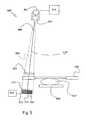
- a preferred embodiment of an x-ray imaging apparatus 500preferably but not exclusively for mammography is illustrated in fig. 5 .
- 501denotes an X-ray source
- 502is a first rough collimator
- 503a second collimator
- 504is a detector array comprising a plurality of detector arrangements
- 505 and 506are lower upper holders, respectively, both transparent to x-rays
- 507is an object to be examined and 508 a support.
- the field of view between beamsis denoted with 509 and also illustrated with dotted lines.
- the X-ray object 507 for mammographyis the female breast and this is compressed according to the standard technique using compression holders 505 and 506, the ends of the latter being arranged with x-ray blocking material.
- a second collimator 510is also provided, the slots of which are matched to the collimator 503 above so that the X-rays coming straight from the source, without deflections, and pass collimator 503 will also pass collimator 510.
- the sensor arrangementcomprising an array of detectors 511 is placed under each slot in such a way that all X-rays coming straight from the source without deflections that pass collimator 503 and pass collimator 510 will also hit the detector arrays beneath the slots and are registered by dedicated electronics.
- detector arrangements according to fig. 2aare used and arranged in parallel on a carrier with their longitudinal axis directed towards the plane of the drawing.
- the collimators503 and 510are placed on a mechanical support 508 together with the detector arrays 504. This support is connected to an accurate linear stage that can move the slots relative to the object.
- the scanning pathis illustrated with dashed arrow.
- the stageis computer 513 controlled and equipped with an accurate position reading. While the slots are moving data from the detector arrays are read out, through connections 512 together with the present coordinate according to the position reading. From this information the image is reconstructed.
- the scanning path illustrated hereis a reciprocating movement due to the circular symmetry of the radiation of the x-ray source, the radiation path can be arranged with refractive means to refract the beam into a plane parallel with the plane of the holders, whereby a linear movement of the collimators and detectors will be needed.
- the detectorsare arranged in substantially circular carrier, which in case of a linear movement should be arranged in a flat carrier.
- the field of viewi.e. the area where its possible to image an object with a scan is defined by the ends of upper holder 506 that is equipped with blocking material. It is possible to attach a collimator to holder 506. However, it is not preferred to attach the collimator to the compression holder since they need to be light and easy to handle.
- the blocking materialshould be moved to above the compression holder and rest on its own support.
- the detector arrays and electronicscould for example consist of a scintillator optically connected to a CCD.
- the sensor arrayscould also be made of silicon diodes and a dedicated electronic circuit could count each X-ray. It would also be possible to use a gaseous detector, such as a Parallel Plate Chamber where the gas volume is oriented edge-on to the incident X-rays and the pulses induced by the X-rays in the gas can be counted by a dedicated electronic circuit. To prevent scattered X-rays from one detector array reaching neighboring detector arrays an absorbing plate such as a thin Copper plate can be inserted between each of the slots.
- the electronic circuitis connected to a computer unit 514 where the data is transferred for manipulation, corrections and display.
- collimatorscan be substituted by refractive or focusing mens.
- a preferred scanning methodis performed as follows: Before the scanning start at least a first part of the collimator 510, e.g. 2/3 of the total number of the collimators are in the field of view while the second part, e.g. 1/3, of the collimators are outside the field of view.
- the scanis started from a first position, e.g. at zero speed, and reaches a maximum substantially constant speed when all collimators and detectors are in the field of view.
- the scanis slowed down and stops when said second part of the collimators are outside the field of view.
- the acceleration time before the scan reaches the maximum speed and the deceleration time before it stopsis determined in such a way that the parts of the image where the acceleration and retardation takes place obtains the same photon statistics as the rest of the image.
- all slots of the collimator 510are placed substantially outside the field of view. After the scan starts it should have reached a constant speed before the first pair of slots (503 and 510) enters the field of view.
- the data containing information about the number of X-rays hitting the detectoris read out as frequently as possible.
- the data for one read outwill consist of a vector of numbers representing the X-ray flux in each of the pixels of the sensor array and this vector will be stored.
- the image resulting from one array of vectorswill consist of a matrix of all the vectors from the individual readouts.
- the width of the sensorsis 50- ⁇ m.
- the datais preferably read out at least every 25- ⁇ m corresponding to half the width of the array. This is to sampling according to the well known Nyquist frequency, which prevent any large loss of information due to sampling in to large steps. It would also prevent artifacts due to aliasing. It is also possible to sample more frequently than this. Sampling steps should not exceed 50- ⁇ m, i.e. the width of the array, since in this case the image for a certain array will be incomplete. Generally, one would like to readout data in time intervals more frequent than it takes for the slots to move a distance equal to half the size of the sensor arrays.
- the scanshould continue until substantially all slots have passed the field of view. There will now be information enough to create one image for the data coming from the sensor arrays for each of the slots. If there are N slots, N images are then obtained and the overall image is formed as the superposition of all said images. This is a straightforward operation and only involves simple superposition of images and there is no need to seem several sub-images together. Dead individual sensors could simply be corrected for since information at this image point also exists in sensors at adjacent slots.
- the sensor arrays in the different slotscould be slightly offset with respect to each other in order to avoid aliasing and sample according to the Nyquist criteria also in the dimension perpendicular to the scan direction.
- the systemwill only be sensitive to motion in the object in a time frame defined by the time it takes the slots to move corresponding to the distance between the first and the last slot. This time Is usually considerably less than the total scan time.
Landscapes
- Health & Medical Sciences (AREA)
- Physics & Mathematics (AREA)
- Life Sciences & Earth Sciences (AREA)
- Spectroscopy & Molecular Physics (AREA)
- Molecular Biology (AREA)
- High Energy & Nuclear Physics (AREA)
- General Physics & Mathematics (AREA)
- Biomedical Technology (AREA)
- Optics & Photonics (AREA)
- Nuclear Medicine, Radiotherapy & Molecular Imaging (AREA)
- Medical Informatics (AREA)
- General Health & Medical Sciences (AREA)
- Engineering & Computer Science (AREA)
- Measurement Of Radiation (AREA)
- Apparatus For Radiation Diagnosis (AREA)
Description
- The present invention relates to an arrangement for detecting x-ray radiations comprising a carrying member on one face arranged with detectors consisting of a plurality of sensors provided on a substrate.
- The invention also relates to -ray apparatus using such an arrangement and a method of scanning in an x-ray apparatus including such an arrangement.
- The usual systems for X-ray imaging consist of an X-ray source and an area detector placed behind the object to register the image. The main drawback with this set-up is its sensitivity to background noise in form of Compton scattered radiation. Existing methods to remove this background are inefficient and also remove a fraction of the primary X-rays that contains the image information. This results in a dose increase that can be as high as a factor 3.
- One way around this problem is a scanned-slot set up. A pre collimator slot before the object shapes the X-ray beam to match the active detector area. The slot is moved mechanically to image the whole object. It is also possible to have the object moving with respect to the slot, this is however usually more inconvenient because the object is usually heavier than the mechanics for the slot. Since only a narrow fan-beam is crossing the object at any single time, the amount of Compton scattered X-rays is minimized. Another advantage with the scanned-slot approach is that the required detector area is much smaller, this cuts cost and also enables the use of more expensive and efficient detector materials if desired.
- A drawback with the scanned-slot geometry is that only a small fraction of the X-rays from the source is actually used to form the image. As a result, the time for image acquisition is extended and the X-ray tube need to be turned on for a longer period of time. A way of mitigating this problem and achieving a practical system is to use a multi slot collimator with different detector arrays under each slot. This however makes the image acquisition non-trivial since the information from the different detectors has to be combined together into one image without any visible artifacts such as boarder lines between areas where different detectors were used.
US 5,461,653 describes a filmless X-ray imaging system including at least one X-ray source, upper and lower collimators, and a solid-state detector array, and can provide three-dimensional imaging capability. The X-ray source plane is distance z1 above upper collimator plane, distance z2 above the lower collimator plane, and distance z3 above the plane of the detector array. The object to be X-rayed is located between the upper and lower collimator planes. The upper and lower collimators and the detector array are moved horizontally with scanning velocities v1, v2, v3 proportional to z1, z2 and z3, respectively. The pattern and size of openings in the collimators, and between detector positions is proportional such that similar triangles are always defined relative to the location of the X-ray source. X-rays that pass through openings in the upper collimator will always pass through corresponding and similar openings in the lower collimator, and thence to a corresponding detector in the underlying detector array. Substantially 100% of the X-rays irradiating the object (and neither absorbed nor scattered) pass through the lower collimator openings and are detected, which promotes enhanced sensitivity. A computer system coordinates repositioning of the collimators and detector array, and X-ray source locations. The computer system can store detector array output, and can associate a known X-ray source location with detector array output data, to provide three-dimensional imaging. Detector output may be viewed instantly, stored digitally, and/or transmitted electronically for image viewing at a remote site.- A method and apparatus for detecting x-ray radiation in a radiographic imaging context using so-called "edge-on" detectors are disclosed in
US 4,937,453 (in the following referred to as patent '453). It is particularly useful in conjunction with slit and slot scan radiography. In accordance with this invention, detectors are constructed and arranged such that substantially all of the energy from an X-ray to be detected is discharged in the detector. In this way a detector is provided which provides a direct electronic read out, high X-ray stopping power and high spatial resolution while obtaining good signal collection efficiency without the use of excessively high voltage levels. In the preferred embodiment, solid state x-ray detectors are constructed such that the thickness of the detector along the direction of incident x-rays is long enough that substantially all of the x-ray energy is discharged in the detector. - The pending European patent application No.
00915678.7 GB2278765 WO98/04193 A - The main object of the present invention is to overcome the problems stated above and present a method to solve the problem of acquiring a high quality image without artifacts using, a single or multi-slot detector system.
- Another object of the present invention is to provide an X-ray apparatus for detecting x-ray radiations in the form of incident X-rays, that simplifies the image scanning and acquisition in an x-ray imaging system.
- A particular advantage of the present invention is the robustness of the system with respect to non-functioning, so called dead, channels and the low sensitivity to deterioration of spatial resolution due to motion in the object.
- According to one embodiment, the system comprising
a X-ray source (501) for providing said incident X-rays having a field of view;
a collimator (502);
an essentially planar beam directing member (503, 510) of a material non-transparent to X-rays, having an elongated slot (401 a, 401 b) formed therein;
a detector system comprising a carrying member (1 10), which comprises at least on one side (111) detectors (130, 130a, 1 30b, 630), said detectors comprising a plurality of sensors (132) arranged on a substrate (131), each detector having an active section and an inactive section,
wherein said inactive section comprises a guard ring (133) and an edge portion (134), that said detectors (130, 130a, 130b, 630) are arranged substantially edge to edge and side by side in at least two rows, a first and a second row on at least said one side of said carrying member, that said detectors on said first row are arranged displaced relative to said detectors in said second row such that an inactive section (133,134) on one detector in said first row is 20 overlapped with an active section of a detector in said second row, and that said plurality of sensors (132) are arranged in a sensor plane and that said carrying member (110) is tilted to arrange said sensor plane at an angle (a) with respect to said incident X-rays. - According to one embodiment, said detector system further comprises a supporting member (201) supporting said detectors.
- According to one embodiment, said detectors consist of one of a scintillator optically connected to a CCD, silicon diodes, a gaseous detector.
- According to one embodiment, said X-ray apparatus comprising:
- said detectors (504) arranged in a at least a first and a second row provided in communication with said slots and arranged to detect said incident X-rays and for providing a signal representing the intensity of said X-rays impinging thereon, and
- means for moving said essentially beam directing member (503, 510) and an object (507) to be examined relative each other
- According to one embodiment, said apparatus comprising means to acquire data from said detectors (504) arranged in a at least a first and a second row at intervals corresponding to a fraction of the width of said sensors.
- According to one embodiment, said essentially planar beam directing member (503,510) is arranged with slots (401a) in at least two rows, wherein each slots in each row are displaced relative to each other.
- According to one embodiment, said essentially planar beam directing member is a refracting or focusing member.
- According to one embodiment, wherein a method for scanning in an apparatus comprises the steps:
- First, arranging a first part of said essentially planar beam directing member (510) in a field of view while the second part of the essentially planar beam directing member is outside the field of view,
- Thereafter, starting the scan from a first position wherein said essentially planar beam directing member has detectors having a first speed,
- bringing the said essentially planar beam directing member and detectors to a maximum, substantially constant speed when the entire essentially planar beam directing member and all detectors are in the field of view, and
- when the first part of said essentially planar beam directing member is outside the field of view, bringing said essentially planar beam directing member and detectors to a third speed.
- According to one embodiment, wherein the method comprises the further step of stopping the scan when said second part of the essentially planar beam directing member is outside the field of view.
- According to one embodiment, wherein the method comprises that the scan is continuous and that readout of data is performed at intervals corresponding to a fraction of the width of said sensors.
- According to one embodiment, wherein the method comprises that the read-out data for each increment and for each detector system are stored as data arrays, that the stored data for each detector system are separately combined to form an image, and that images obtained by detector system are superposed to form a final image.
- In the following, the invention will be further described in a non-limiting way with reference to the accompanying drawings in which:
- Fig. 1
- is a schematic frontal view of a detector assembly according to the invention;
- Figs. 2a; 2b
- are cross-sections along line II-II in
fig 1 , showing two alternative embodiments; - Figs. 3a; 3b
- are enlargements of the encircled area in
fig. 1 , showing two alternative embodiments; - Figs. 4a; 4b
- illustrate two alternative embodiments of a collimator;
- Fig. 5
- shows a first embodiment of an x-ray imaging apparatus in a schematic way,
- Fig. 6
- shows a second embodiment of the detector assembly according to the invention in a schematic way, and
- Fig. 7
- is a schematic top view of a collimator corresponding to the embodiment of
fig. 6 . - A preferred embodiment of an
detector arrangement 100 for detectingX-ray radiations 120 is illustrated infigs. 1, 2a and 2b . Thedetector arrangement 100 comprises a carryingmember 110, on which a number ofdetectors 130, as described in above patent Application00915678.7 - The carrying
member 110 is a substantially rectangular piece made of suitable material. The carryingmember 110 is a standard printed circuit board available from a multitude of manufacturers or it could be a ceramic of similar type as used to carry the chips in Multi Chip Modules. Its important that the carrying member is mechanically stable and that the expansion with temperature is similar in magnitude to the expansion of the detectors (silicon chips) attached to its surface. The carrying member has afirst side 111 and asecond side 112, afirst end 113 and asecond end 114. The first side is arranged with supportingmembers 201 for supporting edge-on arrangeddetectors detectors 130 are arranged spaced apart in two rows in the transverse direction of the carrying member. Thespace 140 corresponds substantially to the length of adetector 130. The detectors in each row are displaced relative each other such that a space in a row corresponds to a detector in the other row. The space between the detector edges at each row, i.e. the space between the bottom edge of an upper detector and top edge of the lower detector, is so provided that a substantially continuous detector surface is provided. Detectors 130a infig. 2a refer to detectors according to Application00915678.7 detectors 130b infig. 2b refer to detectors according to Patent >453. Infig. 2a thedetectors 130a are tilted in an acute angel α by tilting the carryingmember 110, whereby the radiation incide onto a surface of the detectors incorporating sensors in the acute angle α. The detectors may also be tilted by tilting the supportingmembers 201 or using biased detector substrates. The supporting members may also comprise of an adhesive agent for adhering the detectors onto the carrying member. Although, rectangular shaped detectors are illustrated, it is obvious that the detectors having other shapes can also be engaged.- In the embodiment according to
fig. 2b , thedetectors 130b are arranged in parallel to theincident X-rays 120 whereby the rays hit the top edges of the detectors as described in Patent >453. - The reason for displacement of the detectors relative each other in each row is that the edges of each detector is provided with a dead zone and a so-called guard ring. The encircled corner sections of two
detectors 130 are illustrated enlarged infigs. 3a and 3b . Eachdetector 130 comprisessemiconductive substrate 131 on which a number of strips ofpixel sensors 132 on a front side of the detector. The edge of the detector comprise aguard ring 133 an adead area 134. The dead 134 area corresponds approximately to the distance from the edge of the detector to a point in between the guard ring and where the strips of thesensors 132 begin. Eachpixel sensor 132 is connected to electronics of an x-ray imaging apparatus through not shown pads or contacts. - According to
fig. 3a thedetectors 130 are arranged with the active areas, i.e. the area within the guard rings, and more specifically between the guard rings and the adjacent pixel sensors, substantially edge to edge. In the illustrated case, apixel sensor 132 in a detector of a first line is aligned to a guard ring section of a detector in the second line. Consequently, when processing the signals from the detectors the guard rings and dead areas will not effect the output. - According to the embodiment of
fig. 3b , the active areas. The active area of each detector is axially displaced so much that even the pixel sensors overlap. The overlapping may approximately be by 20-150 µm, to allow for possible misalignments. Figs. 4a and 4b show top views of twocollimators collimator 400a corresponds to the detector arrangement according to embodiment offig. 2a and thecollimator 400b to the detector arrangement according to embodiment offig. 2b . The collimators comprisesslots slots 401a, infig. 4a are arranged displaced relative each other corresponding to the configuration of the detectors infig. 2a . Theslot 401b infig. 4b is an oblong slot substantially covering alldetectors 130b.- A good material for collimators is Tungsten since it has a high stopping power and very small scattering probability for the X-rays. The collimators could also be made of other heavy metals such as copper, stainless steel, lead or the like.
- It is also possible to arrange the
detectors 630 in one substantially straight row as shown in thedetector arrangement 600 offig. 6 . The detectors are arranged side by side and edge to edge and the onlyeffective space 640 is provided by the dead area. Theentire detector arrangement 600 can be tilted or arranged substantially perpendicular (to the plane of movement) according to the embodiments offigs. 2a and 2b . A correspondingcollimator 700 is illustrated infig. 7 . Theslots 701 of the collimator are delimited from each other by means ofwalls 702 corresponding essentially to the "space" 640. - A preferred embodiment of an
x-ray imaging apparatus 500, preferably but not exclusively for mammography is illustrated infig. 5 . 501 denotes an X-ray source, 502 is a first rough collimator, 503 a second collimator, 504 is a detector array comprising a plurality of detector arrangements, 505 and 506 are lower upper holders, respectively, both transparent to x-rays; 507 is an object to be examined and 508 a support. The field of view between beams is denoted with 509 and also illustrated with dotted lines. TheX-ray object 507 for mammography is the female breast and this is compressed according to the standard technique usingcompression holders collimator 503 above so that the X-rays coming straight from the source, without deflections, and passcollimator 503 will also pass collimator 510. After the collimator 510, the sensor arrangement comprising an array ofdetectors 511 is placed under each slot in such a way that all X-rays coming straight from the source without deflections that passcollimator 503 and pass collimator 510 will also hit the detector arrays beneath the slots and are registered by dedicated electronics. In this case detector arrangements according tofig. 2a are used and arranged in parallel on a carrier with their longitudinal axis directed towards the plane of the drawing. The collimators503 and 510 are placed on amechanical support 508 together with thedetector arrays 504. This support is connected to an accurate linear stage that can move the slots relative to the object. The scanning path is illustrated with dashed arrow. The stage iscomputer 513 controlled and equipped with an accurate position reading. While the slots are moving data from the detector arrays are read out, throughconnections 512 together with the present coordinate according to the position reading. From this information the image is reconstructed. Although the scanning path illustrated here is a reciprocating movement due to the circular symmetry of the radiation of the x-ray source, the radiation path can be arranged with refractive means to refract the beam into a plane parallel with the plane of the holders, whereby a linear movement of the collimators and detectors will be needed. Moreover, due to the circular radiation, the detectors are arranged in substantially circular carrier, which in case of a linear movement should be arranged in a flat carrier. - The field of view, i.e. the area where its possible to image an object with a scan is defined by the ends of
upper holder 506 that is equipped with blocking material. It is possible to attach a collimator toholder 506. However, it is not preferred to attach the collimator to the compression holder since they need to be light and easy to handle. The blocking material should be moved to above the compression holder and rest on its own support. - The detector arrays and electronics could for example consist of a scintillator optically connected to a CCD. The sensor arrays could also be made of silicon diodes and a dedicated electronic circuit could count each X-ray. It would also be possible to use a gaseous detector, such as a Parallel Plate Chamber where the gas volume is oriented edge-on to the incident X-rays and the pulses induced by the X-rays in the gas can be counted by a dedicated electronic circuit. To prevent scattered X-rays from one detector array reaching neighboring detector arrays an absorbing plate such as a thin Copper plate can be inserted between each of the slots. The electronic circuit is connected to a
computer unit 514 where the data is transferred for manipulation, corrections and display. - Obviously, one or several of collimators can be substituted by refractive or focusing mens.
- A preferred scanning method according to the invention is performed as follows: Before the scanning start at least a first part of the collimator 510, e.g. 2/3 of the total number of the collimators are in the field of view while the second part, e.g. 1/3, of the collimators are outside the field of view. The scan is started from a first position, e.g. at zero speed, and reaches a maximum substantially constant speed when all collimators and detectors are in the field of view. When the first collimator is outside the field of view the scan is slowed down and stops when said second part of the collimators are outside the field of view. The acceleration time before the scan reaches the maximum speed and the deceleration time before it stops is determined in such a way that the parts of the image where the acceleration and retardation takes place obtains the same photon statistics as the rest of the image.
- With this method, it might be technically more difficult to reconstruct the image but from a practical point of view, but experiments have shown that it is important not to have to much of dead area in this direction since the detector in the case of mammography should go all the way up to the armpit of the patient. If there is mm between each line of detectors and 30 lines and assuming that 2/3 of the detectors is outside the field of view when starting the scan the dead area will only extend 10 mm.
- According to another method, before the scan starts all slots of the collimator 510 are placed substantially outside the field of view. After the scan starts it should have reached a constant speed before the first pair of slots (503 and 510) enters the field of view. During the scan, the data containing information about the number of X-rays hitting the detector is read out as frequently as possible. The data for one read out will consist of a vector of numbers representing the X-ray flux in each of the pixels of the sensor array and this vector will be stored. When the scan is finished the image resulting from one array of vectors will consist of a matrix of all the vectors from the individual readouts.
- If there is mm between each line of detectors and 30 lines 30 mm of dead area will be obtained according to this method.
- To be more specific about the read out rate, following example is given, assuming that the width of the sensors is 50-µm. In this case the data is preferably read out at least every 25-µm corresponding to half the width of the array. This is to sampling according to the well known Nyquist frequency, which prevent any large loss of information due to sampling in to large steps. It would also prevent artifacts due to aliasing. It is also possible to sample more frequently than this. Sampling steps should not exceed 50-µm, i.e. the width of the array, since in this case the image for a certain array will be incomplete. Generally, one would like to readout data in time intervals more frequent than it takes for the slots to move a distance equal to half the size of the sensor arrays.
- The scan should continue until substantially all slots have passed the field of view. There will now be information enough to create one image for the data coming from the sensor arrays for each of the slots. If there are N slots, N images are then obtained and the overall image is formed as the superposition of all said images. This is a straightforward operation and only involves simple superposition of images and there is no need to seem several sub-images together. Dead individual sensors could simply be corrected for since information at this image point also exists in sensors at adjacent slots. The sensor arrays in the different slots could be slightly offset with respect to each other in order to avoid aliasing and sample according to the Nyquist criteria also in the dimension perpendicular to the scan direction.
- The system will only be sensitive to motion in the object in a time frame defined by the time it takes the slots to move corresponding to the distance between the first and the last slot. This time Is usually considerably less than the total scan time.
- The invention is not limited the shown embodiments but can be varied in a number of ways without departing from the scope of the appended claims and the arrangement and the method can be implemented in various ways depending on application, functional units, needs and requirements etc. For example a combination of arrangements could also be provided.
Claims (11)
- An X-ray apparatus (500) for detecting x-ray radiations in the form of incident X-rays, said system comprising
a X-ray source (501) for providing said incident X-rays having a field of view;
a collimator (502);
an essentially planar beam directing member (503, 510) of a material non-transparent to X-rays, having an elongated slot (401 a, 401 b) formed therein;
a detector system comprising a carrying member (110), which comprises at least on one side (111) detectors (130, 130a, 130b, 630), said detectors comprising a plurality of sensors (132) arranged on a substrate (131), each detector having an active section and an inactive section,
characterized in
that said inactive section comprises a guard ring (133) and an edge portion (134), that said detectors (130, 130a, 130b, 630) are arranged substantially edge to edge and side by side in at least two rows, a first and a second row on at least said one side of said carrying member, that said detectors on said first row are arranged displaced relative to said detectors in said second row such that an inactive section (133,134) on one detector in said first row is overlapped with an active section of a detector in said second row, and that said plurality of sensors (132) are arranged in a sensor plane and that said carrying member (110) is tilted to arrange said sensor plane at an angle (a) with respect to said incident X-rays. - The X-ray apparatus according to claim 1,characterized in that said detector system further comprises a supporting member (201) supporting said detectors.
- The X-ray apparatus according to any of previous claims,
characterized in
that the detectors consist of one of a scintillator optically connected to a CCD, silicon diodes, a gaseous detector. - The X-ray apparatus (500) according to claim 1, said X-ray apparatus comprising:● said detectors (504) arranged in a at least a first and a second row provided in communication with said slots and arranged to detect said incident X-rays and for providing a signal representing the intensity of said X-rays impinging thereon, and● means for moving said essentially beam directing member (503, 510) and an object (507) to be examined relative each other
- The apparatus according to claim 4, further comprising means to acquire data from said detectors (504) arranged in at least a first and a second row at intervals corresponding to a fraction of the width of said sensors.
- The apparatus according to anyone of claims 4 -5,
characterized in
that said essentially planar beam directing member (503,510) is arranged with slots (401a) in at least two rows, wherein each slots in each row are displaced relative to each other. - The apparatus according to anyone of claims 4 - 6,
characterized in
that said essentially planar beam directing member is a refracting or focusing member. - A method for scanning in an apparatus according to any of claims 4 - 7,characterized by
● First, arranging a first part of said essentially planar beam directing member (510) in a field of view while the second part of the essentially planar beam directing member is outside the field of view,
● Thereafter, starting the scan from a first position wherein said essentially planar beam directing member has detectors having a first speed,
● bringing the said essentially planar beam directing member and detectors to a maximum, substantially constant speed when the entire essentially planar beam directing member and all detectors are in the field of view, and
● when the first part of said essentially planar beam directing member is outside the field of view, bringing said essentially planar beam directing member and detectors to a third speed. - The method according to claim 8,
characterized by the further step of stopping the scan when said second part of the essentially planar beam directing member is outside the field of view. - The method according to claim 9,
characterized in
that the scan is continuous and that readout of data is performed at intervals corresponding to a fraction of the width of said sensors. - The method as claimed in any of claims 10,
characterized in
that the read-out data for each increment and for each detector system are stored as data arrays, that the stored data for each detector system are separately combined to form an image, and that images obtained by detector system are superposed to form a final image.
Applications Claiming Priority (7)
| Application Number | Priority Date | Filing Date | Title |
|---|---|---|---|
| SE9900922 | 1999-03-15 | ||
| SE9900922ASE9900922D0 (en) | 1999-03-15 | 1999-03-15 | Device and method for scanning and image acquisiton with multi-slot collimator system for x-ray imaging |
| US15733399P | 1999-10-01 | 1999-10-01 | |
| US157333P | 1999-10-01 | ||
| SE9903559 | 1999-10-01 | ||
| SE9903559ASE515983C2 (en) | 1999-03-15 | 1999-10-01 | X-ray radiation detecting arrangement for X-ray imaging system, has detectors arranged from one edge to other in row on one face of carrying printed circuit board |
| PCT/SE2000/000524WO2000055645A1 (en) | 1999-03-15 | 2000-03-15 | Device and method relating to x-ray imaging |
Publications (2)
| Publication Number | Publication Date |
|---|---|
| EP1192479A1 EP1192479A1 (en) | 2002-04-03 |
| EP1192479B1true EP1192479B1 (en) | 2013-05-29 |
Family
ID=27355957
Family Applications (1)
| Application Number | Title | Priority Date | Filing Date |
|---|---|---|---|
| EP00917581.1AExpired - LifetimeEP1192479B1 (en) | 1999-03-15 | 2000-03-15 | Device and method relating to x-ray imaging |
Country Status (4)
| Country | Link |
|---|---|
| US (1) | US7212605B2 (en) |
| EP (1) | EP1192479B1 (en) |
| AU (1) | AU3853300A (en) |
| WO (1) | WO2000055645A1 (en) |
Cited By (1)
| Publication number | Priority date | Publication date | Assignee | Title |
|---|---|---|---|---|
| WO2015022600A1 (en) | 2013-08-15 | 2015-02-19 | Koninklijke Philips N.V. | X-ray apparatus |
Families Citing this family (29)
| Publication number | Priority date | Publication date | Assignee | Title |
|---|---|---|---|---|
| US7136452B2 (en)* | 1995-05-31 | 2006-11-14 | Goldpower Limited | Radiation imaging system, device and method for scan imaging |
| SE9900856L (en)* | 1999-03-10 | 2000-11-10 | Mamea Imaging Ab | Method and apparatus for detecting x-rays and use of such apparatus |
| FI120561B (en)* | 2000-03-07 | 2009-11-30 | Planmeca Oy | Digital camera, imaging device and method in digital imaging |
| SE0200447L (en) | 2002-02-15 | 2003-08-16 | Xcounter Ab | Radiation detector arrangement |
| SE524380C2 (en)* | 2002-03-12 | 2004-08-03 | Xcounter Ab | Exposure control in scanner-based detection of ionizing radiation |
| US6912266B2 (en)* | 2002-04-22 | 2005-06-28 | Siemens Aktiengesellschaft | X-ray diagnostic facility having a digital X-ray detector and a stray radiation grid |
| US8320301B2 (en)* | 2002-10-25 | 2012-11-27 | Qualcomm Incorporated | MIMO WLAN system |
| DE102004014445B4 (en)* | 2004-03-24 | 2006-05-18 | Yxlon International Security Gmbh | Secondary collimator for an X-ray diffraction device and X-ray diffraction device |
| JP4307406B2 (en)* | 2005-04-22 | 2009-08-05 | 株式会社モリタ製作所 | Medical X-ray imaging apparatus and X-ray detector used therefor |
| US7212604B2 (en)* | 2005-06-29 | 2007-05-01 | General Electric Company | Multi-layer direct conversion computed tomography detector module |
| JP2007125086A (en)* | 2005-11-01 | 2007-05-24 | Ge Medical Systems Global Technology Co Llc | X-ray detector and x-ray ct apparatus |
| US20080023636A1 (en)* | 2006-07-25 | 2008-01-31 | Samir Chowdhury | Tungsten polymer collimator for medical imaging |
| US7638776B2 (en)* | 2006-08-21 | 2009-12-29 | Endicott Interconnect Technologies, Inc. | Staggered array imaging system using pixilated radiation detectors |
| KR100907821B1 (en)* | 2007-05-29 | 2009-07-14 | 차영진 | Composite image taking device for dental medical diagnosis |
| US8378310B2 (en)* | 2009-02-11 | 2013-02-19 | Prismatic Sensors Ab | Image quality in photon counting-mode detector systems |
| US8183535B2 (en)* | 2009-02-11 | 2012-05-22 | Mats Danielsson | Silicon detector assembly for X-ray imaging |
| US9417213B1 (en)* | 2011-07-11 | 2016-08-16 | The Boeing Company | Non-destructive evaluation system for aircraft |
| CN102599926A (en)* | 2012-04-13 | 2012-07-25 | 杭州美诺瓦医疗科技有限公司 | Scanning detector consisting of multiple sensors |
| JP2015161594A (en)* | 2014-02-27 | 2015-09-07 | 日立アロカメディカル株式会社 | radiation detector |
| WO2016093140A1 (en) | 2014-12-09 | 2016-06-16 | 雫石 誠 | Imaging device |
| JP6689892B2 (en)* | 2015-06-26 | 2020-04-28 | プリズマティック、センサーズ、アクチボラグPrismatic Sensors Ab | Scattering estimation and / or correction in radiography |
| US10271803B2 (en) | 2015-11-12 | 2019-04-30 | Prismatic Sensors Ab | High-resolution computed tomography using edge-on detectors with temporally offset depth-segments |
| CN109690351B (en)* | 2016-09-23 | 2022-12-09 | 深圳帧观德芯科技有限公司 | Packaging of Semiconductor X-ray Detectors |
| US10575800B2 (en)* | 2017-03-08 | 2020-03-03 | Prismatic Sensors Ab | Increased spatial resolution for photon-counting edge-on x-ray detectors |
| EP3807677B1 (en)* | 2018-06-13 | 2024-07-03 | Prismatic Sensors AB | X-ray detector design |
| DE102019202442A1 (en)* | 2019-02-22 | 2020-08-27 | Bruker Axs Gmbh | Measurement arrangement for X-rays for a gap-free 1D measurement |
| DE102019209188B4 (en)* | 2019-06-25 | 2021-01-28 | Bruker Axs Gmbh | Measurement arrangement for X-rays with reduced parallax effects |
| CN110664422A (en)* | 2019-09-09 | 2020-01-10 | 东软医疗系统股份有限公司 | Detector module, detector and medical imaging equipment |
| WO2022109869A1 (en) | 2020-11-25 | 2022-06-02 | Shenzhen Xpectvision Technology Co., Ltd. | Imaging method |
Citations (6)
| Publication number | Priority date | Publication date | Assignee | Title |
|---|---|---|---|---|
| GB2056671A (en)* | 1979-07-30 | 1981-03-18 | American Science & Eng Inc | High resoltuion radiation detector |
| EP0229497A1 (en)* | 1985-12-11 | 1987-07-22 | FutureTech Industries, Inc. | X-ray imaging system and method |
| EP0262267A1 (en)* | 1986-09-30 | 1988-04-06 | Shimadzu Corporation | Radiation image detecting apparatus |
| GB2240003A (en)* | 1989-09-14 | 1991-07-17 | Ricoh Kk | Image reading device |
| GB2278765A (en)* | 1993-06-03 | 1994-12-07 | Eev Ltd | Imaging arrangements |
| WO1998004193A1 (en)* | 1996-07-25 | 1998-02-05 | Analogic Corporation | X-ray tomography system with substantially continuous radiation detection zone |
Family Cites Families (9)
| Publication number | Priority date | Publication date | Assignee | Title |
|---|---|---|---|---|
| FR2561415B1 (en)* | 1984-03-16 | 1990-01-19 | Thomson Csf | IMAGE RECONSTRUCTION METHOD BY COMPUTER TOMODENSITOMETRY |
| US4953189A (en)* | 1985-11-14 | 1990-08-28 | Hologic, Inc. | X-ray radiography method and system |
| US4937453A (en)* | 1987-05-06 | 1990-06-26 | Nelson Robert S | X-ray detector for radiographic imaging |
| US4873708A (en)* | 1987-05-11 | 1989-10-10 | General Electric Company | Digital radiographic imaging system and method therefor |
| US5132995A (en)* | 1989-03-07 | 1992-07-21 | Hologic, Inc. | X-ray analysis apparatus |
| DE4227096A1 (en)* | 1992-08-17 | 1994-02-24 | Philips Patentverwaltung | X-ray image detector |
| US5461653A (en)* | 1993-11-05 | 1995-10-24 | University Of Hawaii | Method and apparatus for enhanced sensitivity filmless medical x-ray imaging, including three-dimensional imaging |
| US5834782A (en)* | 1996-11-20 | 1998-11-10 | Schick Technologies, Inc. | Large area image detector |
| DE19827022C2 (en)* | 1998-06-17 | 2002-01-03 | Siemens Ag | Medical device |
- 2000
- 2000-03-15AUAU38533/00Apatent/AU3853300A/ennot_activeAbandoned
- 2000-03-15EPEP00917581.1Apatent/EP1192479B1/ennot_activeExpired - Lifetime
- 2000-03-15WOPCT/SE2000/000524patent/WO2000055645A1/enactiveApplication Filing
- 2001
- 2001-09-17USUS09/682,540patent/US7212605B2/ennot_activeExpired - Fee Related
Patent Citations (6)
| Publication number | Priority date | Publication date | Assignee | Title |
|---|---|---|---|---|
| GB2056671A (en)* | 1979-07-30 | 1981-03-18 | American Science & Eng Inc | High resoltuion radiation detector |
| EP0229497A1 (en)* | 1985-12-11 | 1987-07-22 | FutureTech Industries, Inc. | X-ray imaging system and method |
| EP0262267A1 (en)* | 1986-09-30 | 1988-04-06 | Shimadzu Corporation | Radiation image detecting apparatus |
| GB2240003A (en)* | 1989-09-14 | 1991-07-17 | Ricoh Kk | Image reading device |
| GB2278765A (en)* | 1993-06-03 | 1994-12-07 | Eev Ltd | Imaging arrangements |
| WO1998004193A1 (en)* | 1996-07-25 | 1998-02-05 | Analogic Corporation | X-ray tomography system with substantially continuous radiation detection zone |
Cited By (2)
| Publication number | Priority date | Publication date | Assignee | Title |
|---|---|---|---|---|
| WO2015022600A1 (en) | 2013-08-15 | 2015-02-19 | Koninklijke Philips N.V. | X-ray apparatus |
| US9693438B2 (en) | 2013-08-15 | 2017-06-27 | Koninklijke Philips N.V. | X-ray apparatus |
Also Published As
| Publication number | Publication date |
|---|---|
| US7212605B2 (en) | 2007-05-01 |
| EP1192479A1 (en) | 2002-04-03 |
| WO2000055645A1 (en) | 2000-09-21 |
| AU3853300A (en) | 2000-10-04 |
| WO2000055645B1 (en) | 2000-12-07 |
| US20020018543A1 (en) | 2002-02-14 |
Similar Documents
| Publication | Publication Date | Title |
|---|---|---|
| EP1192479B1 (en) | Device and method relating to x-ray imaging | |
| US6587710B1 (en) | Hand-held gamma camera | |
| US4095107A (en) | Transaxial radionuclide emission camera apparatus and method | |
| US6794653B2 (en) | SPECT for breast cancer detection | |
| US5781606A (en) | X-ray tomography system with substantially continuous radiation detection zone | |
| EP3532871B1 (en) | Gamma radiation detector with parallax compensation | |
| EP3143428B1 (en) | Eco-scintigraphic probe for medical applications and relative diagnostic method | |
| US5420429A (en) | Multilayer transducer array | |
| EP1996077B1 (en) | Dual-source scanning-based detection of ionizing radiation | |
| US6380540B1 (en) | Radiation imaging using simultaneous emission and transmission | |
| US6429434B1 (en) | Transmission attenuation correction method for PET and SPECT | |
| JPH0634712Y2 (en) | X-ray detector | |
| WO2018044606A1 (en) | Systems and methods for controlling optical coupling between scintillator crystals | |
| US7655915B2 (en) | Collimator assembly for computed tomography system | |
| US4514632A (en) | Modular scintillation camera | |
| US7164143B2 (en) | PET and SPECT systems with attenuation correction | |
| WO1995012884A1 (en) | Method and apparatus for enhanced sensitivity filmless medical x-ray imaging, including three-dimensional imaging | |
| US20070258560A1 (en) | Apparatus and method for determining location of a source of radiation | |
| JP2001153960A (en) | Two-dimensional array type radiation detector | |
| US5917189A (en) | Collimator with multiple field of view and a medical imaging system including a collimator of this type | |
| EP1173856B1 (en) | Method and apparatus for simplified alignment in x-ray imaging | |
| JP2000237178A (en) | X-ray CT system | |
| JPH11295430A (en) | Solid state detector for CT | |
| SE515983C2 (en) | X-ray radiation detecting arrangement for X-ray imaging system, has detectors arranged from one edge to other in row on one face of carrying printed circuit board | |
| Sashin et al. | Improvements in or relating to radiography apparatus |
Legal Events
| Date | Code | Title | Description |
|---|---|---|---|
| PUAI | Public reference made under article 153(3) epc to a published international application that has entered the european phase | Free format text:ORIGINAL CODE: 0009012 | |
| 17P | Request for examination filed | Effective date:20011008 | |
| AK | Designated contracting states | Kind code of ref document:A1 Designated state(s):AT BE CH CY DE DK ES FI FR GB GR IE IT LI LU MC NL PT SE | |
| 17Q | First examination report despatched | Effective date:20060614 | |
| RAP1 | Party data changed (applicant data changed or rights of an application transferred) | Owner name:SECTRA MAMEA AB | |
| REG | Reference to a national code | Ref country code:DE Ref legal event code:R079 Ref document number:60048042 Country of ref document:DE Free format text:PREVIOUS MAIN CLASS: G01T0001240000 Ipc:G01T0001200000 | |
| RIC1 | Information provided on ipc code assigned before grant | Ipc:G01T 1/164 20060101ALI20120927BHEP Ipc:G01T 1/24 20060101ALI20120927BHEP Ipc:G01T 1/20 20060101AFI20120927BHEP | |
| GRAJ | Information related to disapproval of communication of intention to grant by the applicant or resumption of examination proceedings by the epo deleted | Free format text:ORIGINAL CODE: EPIDOSDIGR1 | |
| GRAP | Despatch of communication of intention to grant a patent | Free format text:ORIGINAL CODE: EPIDOSNIGR1 | |
| GRAP | Despatch of communication of intention to grant a patent | Free format text:ORIGINAL CODE: EPIDOSNIGR1 | |
| RAP1 | Party data changed (applicant data changed or rights of an application transferred) | Owner name:PHILIPS DIGITAL MAMMOGRAPHY SWEDEN AB | |
| GRAS | Grant fee paid | Free format text:ORIGINAL CODE: EPIDOSNIGR3 | |
| GRAA | (expected) grant | Free format text:ORIGINAL CODE: 0009210 | |
| AK | Designated contracting states | Kind code of ref document:B1 Designated state(s):AT BE CH CY DE DK ES FI FR GB GR IE IT LI LU MC NL PT SE | |
| REG | Reference to a national code | Ref country code:GB Ref legal event code:FG4D | |
| REG | Reference to a national code | Ref country code:CH Ref legal event code:EP | |
| REG | Reference to a national code | Ref country code:AT Ref legal event code:REF Ref document number:614743 Country of ref document:AT Kind code of ref document:T Effective date:20130615 | |
| REG | Reference to a national code | Ref country code:IE Ref legal event code:FG4D | |
| REG | Reference to a national code | Ref country code:DE Ref legal event code:R096 Ref document number:60048042 Country of ref document:DE Effective date:20130725 | |
| REG | Reference to a national code | Ref country code:AT Ref legal event code:MK05 Ref document number:614743 Country of ref document:AT Kind code of ref document:T Effective date:20130529 | |
| PG25 | Lapsed in a contracting state [announced via postgrant information from national office to epo] | Ref country code:AT Free format text:LAPSE BECAUSE OF FAILURE TO SUBMIT A TRANSLATION OF THE DESCRIPTION OR TO PAY THE FEE WITHIN THE PRESCRIBED TIME-LIMIT Effective date:20130529 Ref country code:SE Free format text:LAPSE BECAUSE OF FAILURE TO SUBMIT A TRANSLATION OF THE DESCRIPTION OR TO PAY THE FEE WITHIN THE PRESCRIBED TIME-LIMIT Effective date:20130529 Ref country code:PT Free format text:LAPSE BECAUSE OF FAILURE TO SUBMIT A TRANSLATION OF THE DESCRIPTION OR TO PAY THE FEE WITHIN THE PRESCRIBED TIME-LIMIT Effective date:20130930 Ref country code:FI Free format text:LAPSE BECAUSE OF FAILURE TO SUBMIT A TRANSLATION OF THE DESCRIPTION OR TO PAY THE FEE WITHIN THE PRESCRIBED TIME-LIMIT Effective date:20130529 Ref country code:ES Free format text:LAPSE BECAUSE OF FAILURE TO SUBMIT A TRANSLATION OF THE DESCRIPTION OR TO PAY THE FEE WITHIN THE PRESCRIBED TIME-LIMIT Effective date:20130909 Ref country code:GR Free format text:LAPSE BECAUSE OF FAILURE TO SUBMIT A TRANSLATION OF THE DESCRIPTION OR TO PAY THE FEE WITHIN THE PRESCRIBED TIME-LIMIT Effective date:20130830 | |
| REG | Reference to a national code | Ref country code:NL Ref legal event code:VDEP Effective date:20130529 | |
| PG25 | Lapsed in a contracting state [announced via postgrant information from national office to epo] | Ref country code:BE Free format text:LAPSE BECAUSE OF FAILURE TO SUBMIT A TRANSLATION OF THE DESCRIPTION OR TO PAY THE FEE WITHIN THE PRESCRIBED TIME-LIMIT Effective date:20130529 Ref country code:DK Free format text:LAPSE BECAUSE OF FAILURE TO SUBMIT A TRANSLATION OF THE DESCRIPTION OR TO PAY THE FEE WITHIN THE PRESCRIBED TIME-LIMIT Effective date:20130529 | |
| PG25 | Lapsed in a contracting state [announced via postgrant information from national office to epo] | Ref country code:NL Free format text:LAPSE BECAUSE OF FAILURE TO SUBMIT A TRANSLATION OF THE DESCRIPTION OR TO PAY THE FEE WITHIN THE PRESCRIBED TIME-LIMIT Effective date:20130529 Ref country code:IT Free format text:LAPSE BECAUSE OF FAILURE TO SUBMIT A TRANSLATION OF THE DESCRIPTION OR TO PAY THE FEE WITHIN THE PRESCRIBED TIME-LIMIT Effective date:20130529 | |
| PLBE | No opposition filed within time limit | Free format text:ORIGINAL CODE: 0009261 | |
| STAA | Information on the status of an ep patent application or granted ep patent | Free format text:STATUS: NO OPPOSITION FILED WITHIN TIME LIMIT | |
| 26N | No opposition filed | Effective date:20140303 | |
| REG | Reference to a national code | Ref country code:DE Ref legal event code:R097 Ref document number:60048042 Country of ref document:DE Effective date:20140303 | |
| PG25 | Lapsed in a contracting state [announced via postgrant information from national office to epo] | Ref country code:LU Free format text:LAPSE BECAUSE OF FAILURE TO SUBMIT A TRANSLATION OF THE DESCRIPTION OR TO PAY THE FEE WITHIN THE PRESCRIBED TIME-LIMIT Effective date:20140315 | |
| REG | Reference to a national code | Ref country code:CH Ref legal event code:PL | |
| REG | Reference to a national code | Ref country code:IE Ref legal event code:MM4A | |
| PG25 | Lapsed in a contracting state [announced via postgrant information from national office to epo] | Ref country code:IE Free format text:LAPSE BECAUSE OF NON-PAYMENT OF DUE FEES Effective date:20140315 Ref country code:CH Free format text:LAPSE BECAUSE OF NON-PAYMENT OF DUE FEES Effective date:20140331 Ref country code:LI Free format text:LAPSE BECAUSE OF NON-PAYMENT OF DUE FEES Effective date:20140331 | |
| REG | Reference to a national code | Ref country code:FR Ref legal event code:PLFP Year of fee payment:17 | |
| PG25 | Lapsed in a contracting state [announced via postgrant information from national office to epo] | Ref country code:MC Free format text:LAPSE BECAUSE OF FAILURE TO SUBMIT A TRANSLATION OF THE DESCRIPTION OR TO PAY THE FEE WITHIN THE PRESCRIBED TIME-LIMIT Effective date:20130529 | |
| PG25 | Lapsed in a contracting state [announced via postgrant information from national office to epo] | Ref country code:CY Free format text:LAPSE BECAUSE OF FAILURE TO SUBMIT A TRANSLATION OF THE DESCRIPTION OR TO PAY THE FEE WITHIN THE PRESCRIBED TIME-LIMIT Effective date:20130529 | |
| REG | Reference to a national code | Ref country code:FR Ref legal event code:PLFP Year of fee payment:18 | |
| PGFP | Annual fee paid to national office [announced via postgrant information from national office to epo] | Ref country code:FR Payment date:20170327 Year of fee payment:18 | |
| PGFP | Annual fee paid to national office [announced via postgrant information from national office to epo] | Ref country code:GB Payment date:20170330 Year of fee payment:18 | |
| PGFP | Annual fee paid to national office [announced via postgrant information from national office to epo] | Ref country code:DE Payment date:20170531 Year of fee payment:18 | |
| REG | Reference to a national code | Ref country code:DE Ref legal event code:R119 Ref document number:60048042 Country of ref document:DE | |
| GBPC | Gb: european patent ceased through non-payment of renewal fee | Effective date:20180315 | |
| PG25 | Lapsed in a contracting state [announced via postgrant information from national office to epo] | Ref country code:DE Free format text:LAPSE BECAUSE OF NON-PAYMENT OF DUE FEES Effective date:20181002 | |
| PG25 | Lapsed in a contracting state [announced via postgrant information from national office to epo] | Ref country code:GB Free format text:LAPSE BECAUSE OF NON-PAYMENT OF DUE FEES Effective date:20180315 | |
| PG25 | Lapsed in a contracting state [announced via postgrant information from national office to epo] | Ref country code:FR Free format text:LAPSE BECAUSE OF NON-PAYMENT OF DUE FEES Effective date:20180331 |