EP1192396B1 - Precooled cryogenic ablation system - Google Patents
Precooled cryogenic ablation systemDownload PDFInfo
- Publication number
- EP1192396B1 EP1192396B1EP00944827AEP00944827AEP1192396B1EP 1192396 B1EP1192396 B1EP 1192396B1EP 00944827 AEP00944827 AEP 00944827AEP 00944827 AEP00944827 AEP 00944827AEP 1192396 B1EP1192396 B1EP 1192396B1
- Authority
- EP
- European Patent Office
- Prior art keywords
- refrigerant
- primary
- primary refrigerant
- gaseous
- heat exchanger
- Prior art date
- Legal status (The legal status is an assumption and is not a legal conclusion. Google has not performed a legal analysis and makes no representation as to the accuracy of the status listed.)
- Expired - Lifetime
Links
- 238000002679ablationMethods0.000titleclaimsabstractdescription7
- 239000003507refrigerantSubstances0.000claimsabstractdescription144
- 238000001816coolingMethods0.000claimsabstractdescription34
- 239000007788liquidSubstances0.000claimsabstractdescription25
- 238000000034methodMethods0.000claimsabstractdescription13
- 229920002614Polyether block amidePolymers0.000claimsdescription2
- 239000004642PolyimideSubstances0.000claimsdescription2
- 229920001721polyimidePolymers0.000claimsdescription2
- 229920000642polymerPolymers0.000claims2
- 238000013022ventingMethods0.000claims1
- 230000008016vaporizationEffects0.000abstractdescription2
- 210000004204blood vesselAnatomy0.000abstract1
- 230000000747cardiac effectEffects0.000abstract1
- 230000002526effect on cardiovascular systemEffects0.000abstract1
- 239000007791liquid phaseSubstances0.000abstract1
- 239000000523sampleSubstances0.000description12
- 238000005057refrigerationMethods0.000description11
- 238000007710freezingMethods0.000description6
- 230000008014freezingEffects0.000description6
- 238000002681cryosurgeryMethods0.000description4
- 239000000203mixtureSubstances0.000description2
- 210000000056organAnatomy0.000description2
- 230000002159abnormal effectEffects0.000description1
- 230000006793arrhythmiaEffects0.000description1
- 206010003119arrhythmiaDiseases0.000description1
- 230000015572biosynthetic processEffects0.000description1
- 238000013153catheter ablationMethods0.000description1
- 230000030833cell deathEffects0.000description1
- 230000006037cell lysisEffects0.000description1
- 239000013078crystalSubstances0.000description1
- 230000006378damageEffects0.000description1
- 230000007423decreaseEffects0.000description1
- PXBRQCKWGAHEHS-UHFFFAOYSA-NdichlorodifluoromethaneChemical compoundFC(F)(Cl)ClPXBRQCKWGAHEHS-UHFFFAOYSA-N0.000description1
- 230000000694effectsEffects0.000description1
- 239000012530fluidSubstances0.000description1
- 230000003834intracellular effectEffects0.000description1
- TXEYQDLBPFQVAA-UHFFFAOYSA-NtetrafluoromethaneChemical groupFC(F)(F)FTXEYQDLBPFQVAA-UHFFFAOYSA-N0.000description1
- 230000000472traumatic effectEffects0.000description1
- 238000009834vaporizationMethods0.000description1
Images
Classifications
- F—MECHANICAL ENGINEERING; LIGHTING; HEATING; WEAPONS; BLASTING
- F25—REFRIGERATION OR COOLING; COMBINED HEATING AND REFRIGERATION SYSTEMS; HEAT PUMP SYSTEMS; MANUFACTURE OR STORAGE OF ICE; LIQUEFACTION SOLIDIFICATION OF GASES
- F25D—REFRIGERATORS; COLD ROOMS; ICE-BOXES; COOLING OR FREEZING APPARATUS NOT OTHERWISE PROVIDED FOR
- F25D3/00—Devices using other cold materials; Devices using cold-storage bodies
- F25D3/10—Devices using other cold materials; Devices using cold-storage bodies using liquefied gases, e.g. liquid air
- A—HUMAN NECESSITIES
- A61—MEDICAL OR VETERINARY SCIENCE; HYGIENE
- A61B—DIAGNOSIS; SURGERY; IDENTIFICATION
- A61B18/00—Surgical instruments, devices or methods for transferring non-mechanical forms of energy to or from the body
- A61B18/02—Surgical instruments, devices or methods for transferring non-mechanical forms of energy to or from the body by cooling, e.g. cryogenic techniques
- A61B2018/0212—Surgical instruments, devices or methods for transferring non-mechanical forms of energy to or from the body by cooling, e.g. cryogenic techniques using an instrument inserted into a body lumen, e.g. catheter
- A—HUMAN NECESSITIES
- A61—MEDICAL OR VETERINARY SCIENCE; HYGIENE
- A61B—DIAGNOSIS; SURGERY; IDENTIFICATION
- A61B18/00—Surgical instruments, devices or methods for transferring non-mechanical forms of energy to or from the body
- A61B18/02—Surgical instruments, devices or methods for transferring non-mechanical forms of energy to or from the body by cooling, e.g. cryogenic techniques
- A61B2018/0231—Characteristics of handpieces or probes
- A61B2018/0262—Characteristics of handpieces or probes using a circulating cryogenic fluid
Definitions
- Field of the Invention -This invention is in the field of cooling biological tissues to very low temperatures, for treatment of medical conditions, as in cryosurgery.
- cryosurgeryhas become an important procedure in medical, dental, and veterinary fields. Particular success has been experienced in the specialties of gynecology and dermatology. Other specialties, such as neurosurgery and urology, could also benefit from the implementation of cryosurgical techniques, but this has only occurred in a limited way.
- cryosurgical instrumentshave several limitations which make their use difficult or impossible in some such fields. Specifically, known systems can not achieve the necessary temperature and cooling power to optimally perform cryosurgical ablation, such as in cardiac ablation to correct arrhythmia.
- cryosurgical application systemdesigned to suitably freeze the target tissue, thereby destroying diseased or degenerated cells in the tissue.
- the abnormal cells to be destroyedare often surrounded by healthy tissue which must be left uninjured.
- the particular probe, catheter, or other applicator used in a given applicationis therefore designed with the optimum shape, size, and flexibility or rigidity for the application, to achieve this selective freezing of tissue.
- the remainder of the refrigeration systemmust be designed to provide adequate cooling, which involves lowering the operative portion of the probe to a desired temperature, and having sufficient power or capacity to maintain the desired temperature for a given heat load.
- the entire systemmust be designed to place the operative portion of the probe or catheter at the location of the tissue to be frozen, without having any undesirable effect on other organs or systems.
- US 5758505relates to a miniature mixed gas refrigeration system in which a compressed gas mixture passes through a primary-to-secondary heat exchanger, and exits as a gas. The gas is then expanded in a primary Joule-Thomson expansion element, with an optional cooling step.
- the present inventioncomprises a miniature refrigeration system, including a method for operating the system, including precooling of the primary high pressure refrigerant below its critical temperature, to liquefy the primary refrigerant, with a secondary refrigeration cycle using a second refrigerant with a higher critical temperature, to maximize the available cooling power of the primary refrigerant, and to achieve the lowest possible temperature.
- the cooling poweris an important design parameter of a cryosurgical instrument. With greater cooling power, more rapid temperature decreases occur, and lower temperatures can be maintained at the probe tip during freezing. This ultimately leads to greater tissue destruction.
- the power of a J-T cryosurgical deviceis a function of the enthalpy difference of the primary refrigerant and the mass flow rate. Pre-cooling a refrigerant below its critical temperature and liquefying the refrigerant will increase the enthalpy difference available for cooling power.
- An example of a suitable primary refrigerantis SUVA-95, a mixture of R-23 and R-116 refrigerants made by DuPont Fluoroproducts, of Wilmington, Delaware.
- SUVA-95has a critical temperature of 287K, with cooling capacity at temperatures as low as 185K at one atmosphere.
- An example of a suitable secondary refrigerantis AZ-20, an R-410a refrigerant made by Allied Signal of Morristown, New Jersey.
- AZ-20has a critical temperature of 345K, with cooling capacity at temperatures as low as 220K at one atmosphere.
- the high pressure primary refrigerantis fed as a gas into a high pressure passageway within a primary-to-secondary heat exchanger.
- the primary-to-secondary heat exchangercan be a coiled tube heat exchanger or a finned tube heat exchanger.
- the liquid secondary refrigerantis vaporized and expanded into a low pressure passageway in the primary-to-secondary heat exchanger. Heat exchange between the low pressure secondary refrigerant vapor and the high pressure primary refrigerant cools and liquefies the high pressure refrigerant.
- the liquid high pressure primary refrigerantis then vaporized and expanded at the cooling tip of a cryosurgical catheter to provide the cooling power necessary for effective ablation of tissue.
- the method and apparatus of the present inventioncan be used equally well in a rigid hand held cryoprobe, or in a catheter.
- the primary-to-secondary heat exchangeris part of the secondary refrigeration system, which can have a secondary compressor and a secondary expansion element, in addition to the primary-to-secondary heat exchanger.
- the liquid high pressure secondary refrigeranthaving a higher critical temperature than the primary refrigerant, can be at a temperature which is relatively higher than the critical temperature of the primary refrigerant.
- the vaporized and expanded low pressure secondary refrigerantis at a temperature which is low enough to cool the primary refrigerant below its critical temperature. Since the secondary refrigerant has a critical temperature above normal operating room temperature, it can easily be provided in the liquid state in an operating room environment, whereas the primary refrigerant, which has a critical temperature significantly below normal operating room temperature, can not.
- the liquid high pressure primary refrigerantis conducted from the heat exchanger to the inlet of a primary Joule-Thomson expansion element located in the cold tip of the probe or catheter, where the primary refrigerant is vaporized and expanded to a lower pressure and a lower temperature.
- the primary refrigerant exiting the primary Joule-Thomson expansion elementis exposed to the inner surface of a heat transfer element at the cold tip.
- the vaporized and expanded primary refrigerantcools the heat transfer element to a lower temperature and then returns through the low pressure return passageway of the catheter or probe.
- the present inventionlies in the appropriate use of a secondary evaporative refrigeration system to precool and liquefy the primary high pressure refrigerant, before passage of the primary refrigerant through a primary Joule-Thomson expansion element. This is intended to enable the generation of a sufficiently low temperature, and to maximize the available cooling power, at the cold tip of a cryosurgical probe or catheter.
- Pre-cooling the primary refrigerant to an at least partially liquid state, prior to feeding it to the primary expansion element,is the focus of the present invention.
- This pre-coolingcan be done prior to introducing the primary refrigerant into the catheter, by the use of a heat exchanger in a cooling console.
- pre-coolingcan be provided nearer to the treatment area, such as in the handle of a cryoprobe, or at the proximal end of a catheter.
- the cooling powerdetermines the rate of cooling in degrees per second, and the temperature which can be maintained at the probe tip during freezing of the tissue.
- the rate of freezingis important in achieving cell death, since more rapid freezing results in better formation of intracellular ice crystals, resulting in cell lysis.
- the rate of freezingalso determines the length of time required to perform a given procedure on the patient. The quicker the procedure, the less traumatic the procedure is to the patient.
- the temperature which can be maintained at the probe cold tipdetermines the size of the ice ball formed in the surrounding tissue. This, of course, determines the total volume of tissue destroyed at each location, and the speed with which the procedure can be completed.
- the cooling power of the deviceis the product of the mass flow rate of the cryogen and the enthalpy difference at the different pressures and temperatures.
- the flow rateis a function of orifice size and the temperature and pressure of the cryogen. For a given orifice size, under non-choking conditions, the density of the cryogen is higher at higher pressures and lower temperatures, resulting in a higher mass flow rate. The maximum flow rate is found at the point where the cryogen is a liquid.
- the enthalpy differenceis also a function of the pressure and temperature.
- the initial cool downis very slow at overcoming the low flow rate.
- the cold tipis typically placed within the patient, and in contact with the target tissue, before commencement of cooldown, placing a significant heat load on the tip. This means that cooldown can be unacceptably slow, and in some cases, it may not occur at all.
- an independent secondary evaporative refrigeration systemis incorporated.
- the primary systemuses a refrigerant such as freon, or SUVA-95, to achieve the desired temperature and capacity at the cold tip.
- the critical temperature of such a refrigerantis below the temperature normally found in the operating room environment, so provision of the primary refrigerant in the liquid state requires precooling.
- the secondary systemuses a refrigerant such as AZ-20, to pre-cool and liquefy the primary refrigerant prior to flow of the primary refrigerant to the cold tip.
- the secondary systemaccomplishes this pre-cooling through a primary-to-secondary heat exchanger. This pre-cooling causes the initial flow rate and the cooling power of the system to be higher, making the initial cooldown rate much faster.
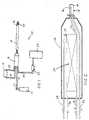
- the apparatus 10 of the present inventionincludes a source of gaseous high pressure primary refrigerant 12, a source of liquid high pressure secondary refrigerant 14, a primary-to-secondary heat exchange unit 16, and a probe or catheter 18 with a cold tip 20.
- the gaseous primary refrigerant source 12can incorporate a pressure bottle as schematically shown, with the primary loop being an open loop, or the source 12 can incorporate a compressor, with the primary loop being a closed loop, as will be explained below.
- the primary refrigerantis one which, in order to deliver the desired temperature and cooling capacity at the cold tip 20, necessarily has a critical temperature below the temperature of the operating room environment.
- a flexible coaxial catheter 18can be constructed with an outer tube made of pebax, and an inner tube made of polyimide.
- Gaseous high pressure primary refrigerantflows from the primary refrigerant source 12 via a conduit 32 into the heat exchange unit 16. After heat exchange and liquefaction, liquid primary refrigerant, at a temperature below the temperature of the operating room environment, flows from the heat exchange unit 16 into the catheter or probe 18. Near the distal tip of the catheter 18, the liquid primary refrigerant is vaporized and expanded at an expansion element shown schematically as an orifice 36. This lowers the temperature of the primary refrigerant to the desired temperature, enabling the refrigerant to cool the cold tip 20 to the selected temperature for tissue ablation. Gaseous primary refrigerant returning from the cold tip 20 exits the heat exhange unit 16 via a conduit 34.
- the primary loopcan be operated as an open loop, and the gaseous primary refrigerant conduit 34 can be collected by a compressor 22 to vent to atmosphere or to a collector 24.
- the primary loopcan be operated as a closed loop, and the gaseous primary refrigerant conduit 32 can be routed (not shown) from the outlet of the compressor 22, as is well know in the art.
- the liquid secondary refrigerant source 14can incorporate a compressor unit as schematically shown, or it can incorporate a pressure bottle. If required to generate the necessary pressure for liquefaction of the secondary refrigerant, a compressor can be used to raise the pressure of the effluent from a pressure bottle.
- the secondary refrigerant source 14can also include a condensor, as is well known in the art, for liquefying the secondary refrigerant, if required.
- the secondary refrigerantmust be one which has a critical temperature above the temperature of the operating room environment, so that the secondary refrigerant can be conducted in liquid form to the primary-to-secondary heat exchange unit 16. This enables the use of the phase-change enthalpy difference in the secondary refrigerant to provide the necessary cooling to take the primary refrigerant below its critical temperature in the heat exchange unit 16.
- Liquid high pressure secondary refrigerantflows from the secondary refrigerant source 14 via a conduit 28 into the heat exchange unit 16. After vaporization and heat exchange, gaseous secondary refrigerant flows from the heat exchange unit 16 via a conduit 30.
- the secondary refrigerant source 14incorporates a pressure bottle
- the secondary loopcan be operated as an open loop, and the gaseous secondary refrigerant conduit 30 can vent to atmosphere or to a collector (not shown) as is well known in the art.
- the secondary loopcan be operated as a closed loop, and the gaseous secondary refrigerant conduit 30 can be routed to the inlet of a compressor in the secondary refrigerant source 14, as shown.
- liquid high pressure secondary refrigerantenters the heat exchange unit 16 via a supply conduit 28 and is vaporized and expanded via a secondary expansion element shown as a capillary tube 29.
- the vaporized and expanded secondary refrigerantat a temperature below the critical temperature of the primary refrigerant, then flows through a secondary refrigerant flow path in a primary-to-secondary heat exchanger 26 and exits the heat exchange unit 16 via a return conduit 30.
- Gaseous high pressure primary refrigerantenters the heat exchange unit 16 via a supply conduit 32 and flows through a primary refrigerant flow path in the heat exchanger 26. Since the temperature of the secondary refrigerant flowing through the heat exchanger 26 is significantly below the critical temperature of the primary refrigerant, the primary refrigerant is liquefied in the heat exchanger 26. Liquid primary refrigerant then exits the heat exchanger via a conduit 33 and flows through the catheter 18 to a primary expansion element, shown schematically as an orifice 36, near the cold tip 20. The primary expansion element 36 vaporizes and expands the primary refrigerant to the selected temperature for cooling the cold tip 20 to the desired temperature for ablation of tissue. The vaporized and expanded primary refrigerant returning from the cold tip 20 then flows back through the catheter 18, through the heat exchange unit 16, and exits the heat exchange unit 16 via a return conduit 34.
- a primary expansion elementshown schematically as an orifice 36
Landscapes
- Health & Medical Sciences (AREA)
- Engineering & Computer Science (AREA)
- Surgery (AREA)
- Life Sciences & Earth Sciences (AREA)
- Nuclear Medicine, Radiotherapy & Molecular Imaging (AREA)
- Biomedical Technology (AREA)
- Medical Informatics (AREA)
- Thermal Sciences (AREA)
- Mechanical Engineering (AREA)
- Physics & Mathematics (AREA)
- Otolaryngology (AREA)
- Combustion & Propulsion (AREA)
- Chemical & Material Sciences (AREA)
- Heart & Thoracic Surgery (AREA)
- General Engineering & Computer Science (AREA)
- Molecular Biology (AREA)
- Animal Behavior & Ethology (AREA)
- General Health & Medical Sciences (AREA)
- Public Health (AREA)
- Veterinary Medicine (AREA)
- Thermotherapy And Cooling Therapy Devices (AREA)
- Surgical Instruments (AREA)
- Saccharide Compounds (AREA)
- Shaping Of Tube Ends By Bending Or Straightening (AREA)
- Treatments Of Macromolecular Shaped Articles (AREA)
Abstract
Description
Claims (12)
- A cryosurgical instrument for ablation of endocardiac tissue,comprising:a source of a gaseous primary refrigerant (12), said source providingsaid primary refrigerant at a temperature above the critical temperature ofsaid primary refrigerant;a source of a liquid secondary refrigerant (14), said secondaryrefrigerant having a critical temperature higher than said critical temperatureof said primary refrigerant;a secondary expansion element (29) connected to receive said liquidsecondary refrigerant, said secondary expansion element being constructed tovaporize and expand said secondary refrigerant to a temperature below saidcritical temperature of said primary refrigerant;a primary-to-secondary heat exchanger (26) having a primaryrefrigerant flow path (32) connected to receive said gaseous primaryrefrigerant, and a secondary refrigerant flow path connected to receive saidvaporized and expanded secondary refrigerant from said secondaryexpansion element, said heat exchanger being constructed to cool and liquefysaid primary refrigerant;a primary expansion element (36) connected to receive said liquidprimary refrigerant from said heat exchanger, said primary expansionelement being constructed to vaporize and expand said primary refrigerant toa selected cryogenic temperature; anda cryoablation heat transfer element (20) connected to receive saidvaporized and expanded primary refrigerant.
- A cryosurgical instrument as recited in claim 1, further comprising aflexible coaxial catheter (18) connected at a proximal end to said primary-to-secondaryheat exchanger (26), said coaxial catheter having an outer low pressure tube and an inner high pressure tube, said primary expansionelement (36) and said heat transfer element (20) being located near a distalend of said flexible catheter.
- A cryosurgical instrument as recited in claim 2, wherein said outertube of said coaxial catheter (18) is constructed of pebax polymer, and saidinner tube of said coaxial catheter is constructed of polyimide polymer.
- A cryosurgical instrument as recited in claim 1, further comprising acompressor unit (14) connected to receive said gaseous secondary refrigerantfrom said heat exchanger (26) and to repressurize, liquefy, and return saidsecondary refrigerant to said secondary expansion element (29).
- A cryosurgical instrument as recited in claim 1, further comprising avent path (30) connected to receive said gaseous secondary refrigerant fromsaid heat exchanger (26).
- A cryosurgical instrument as recited in claim 1, further comprising acompressor unit (22) connected to collect said gaseous primary refrigerantreturning from said heat transfer element (20).
- A cryosurgical instrument as recited in claim 1, further comprising avent path (34) connected to receive said gaseous primary refrigerantreturning from said heat transfer element (20).
- A cryosurgical instrument as recited in claim 1, wherein said primaryrefrigerant has a critical temperature below about 22°C, and said secondaryrefrigerant has a critical temperature above about 22°C.
- A cryosurgical instrument as recited in claim 1, wherein said primaryrefrigerant comprises SUVA-95, and said secondary refrigerant comprisesAZ-20.
- A cryosurgical instrument as recited in claim 1, wherein said sourceof secondary refrigerant comprises a compressor unit (14), and furthercomprising:a secondary refrigerant return path (30), connected to receive saidgaseous secondary refrigerant returning from said heat exchanger (26)and to conduct said gaseous secondary refrigerant to an inlet of saidcompressor unit;a flexible coaxial catheter (18) connected at a proximal end to saidprimary-to-secondary heat exchanger, said coaxial catheter having an outerlow pressure tube and an inner high pressure tube, said primary expansionelement (36) and said heat transfer element (20) being located near a distalend of said flexible catheter; anda vent path connected to receive said gaseous primary refrigerantreturning from said heat transfer element.
- A method for cooling a cryoprobe cold tip (20), said methodcomprising:providing a gaseous primary refrigerant at a temperature above thecritical temperature of said primary refrigerant;providing a liquid secondary refrigerant, said secondary refrigeranthaving a critical temperature higher than said critical temperature of saidprimary refrigerant;providing a primary-to-secondary heat exchanger (26) having aprimary refrigerant flow path and a secondary refrigerant flow path;flowing said gaseous primary refrigerant through said primaryrefrigerant flow path of said heat exchanger;flowing said liquid secondary refrigerant through a secondaryexpansion element (29) to thereby vaporize and expand said secondaryrefrigerant to a temperature below said critical temperature of said primaryrefrigerant;flowing said vaporized and expanded secondary refrigerant from saidsecondary expansion element through said secondary refrigerant flow path ofsaid heat exchanger to cool and liquefy said primary refrigerant;flowing said liquid primary refrigerant through a primary expansionelement (36) to thereby vaporize and expand said primary refrigerant to aselected cryogenic temperature; andexposing said cold tip to said vaporized and expanded primaryrefrigerant.
- A method as recited in claim 11, further comprising:compressing and condensing said gaseous secondary refrigerantexiting from said heat exchanger (26) and returning said secondaryrefrigerant to said secondary expansion element (29); andventing said gaseous primary refrigerant exiting from said cold tip(20).
Applications Claiming Priority (3)
| Application Number | Priority Date | Filing Date | Title |
|---|---|---|---|
| US09/344,423US6237355B1 (en) | 1999-06-25 | 1999-06-25 | Precooled cryogenic ablation system |
| US344423 | 1999-06-25 | ||
| PCT/US2000/017349WO2001001049A1 (en) | 1999-06-25 | 2000-06-23 | Precooled cryogenic ablation system |
Publications (3)
| Publication Number | Publication Date |
|---|---|
| EP1192396A1 EP1192396A1 (en) | 2002-04-03 |
| EP1192396A4 EP1192396A4 (en) | 2003-05-07 |
| EP1192396B1true EP1192396B1 (en) | 2005-06-08 |
Family
ID=23350491
Family Applications (1)
| Application Number | Title | Priority Date | Filing Date |
|---|---|---|---|
| EP00944827AExpired - LifetimeEP1192396B1 (en) | 1999-06-25 | 2000-06-23 | Precooled cryogenic ablation system |
Country Status (9)
| Country | Link |
|---|---|
| US (2) | US6237355B1 (en) |
| EP (1) | EP1192396B1 (en) |
| JP (1) | JP4195560B2 (en) |
| AT (1) | ATE297535T1 (en) |
| AU (1) | AU754357B2 (en) |
| CA (1) | CA2378054C (en) |
| DE (1) | DE60020705T2 (en) |
| ES (1) | ES2242623T3 (en) |
| WO (1) | WO2001001049A1 (en) |
Families Citing this family (92)
| Publication number | Priority date | Publication date | Assignee | Title |
|---|---|---|---|---|
| US6464697B1 (en) | 1998-02-19 | 2002-10-15 | Curon Medical, Inc. | Stomach and adjoining tissue regions in the esophagus |
| US6592577B2 (en) | 1999-01-25 | 2003-07-15 | Cryocath Technologies Inc. | Cooling system |
| US7004936B2 (en)* | 2000-08-09 | 2006-02-28 | Cryocor, Inc. | Refrigeration source for a cryoablation catheter |
| US6471694B1 (en) | 2000-08-09 | 2002-10-29 | Cryogen, Inc. | Control system for cryosurgery |
| US20040215235A1 (en) | 1999-11-16 | 2004-10-28 | Barrx, Inc. | Methods and systems for determining physiologic characteristics for treatment of the esophagus |
| US20060095032A1 (en) | 1999-11-16 | 2006-05-04 | Jerome Jackson | Methods and systems for determining physiologic characteristics for treatment of the esophagus |
| WO2001035846A1 (en) | 1999-11-16 | 2001-05-25 | Ganz Robert A | System and method of treating abnormal tissue in the human esophagus |
| US6430956B1 (en) | 2001-05-15 | 2002-08-13 | Cimex Biotech Lc | Hand-held, heat sink cryoprobe, system for heat extraction thereof, and method therefore |
| US20080051774A1 (en)* | 2001-05-21 | 2008-02-28 | Galil Medical Ltd. | Device and method for coordinated insertion of a plurality of cryoprobes |
| US20030032936A1 (en) | 2001-08-10 | 2003-02-13 | Lederman Robert J. | Side-exit catheter and method for its use |
| US6789545B2 (en)* | 2002-10-04 | 2004-09-14 | Sanarus Medical, Inc. | Method and system for cryoablating fibroadenomas |
| US6893433B2 (en)* | 2002-12-11 | 2005-05-17 | Cryocor, Inc. | System and method for performing a single step cryoablation |
| US6824543B2 (en) | 2002-12-11 | 2004-11-30 | Cryocor, Inc. | Guidance system for a cryocatheter |
| US7195625B2 (en) | 2002-12-11 | 2007-03-27 | Cryocor, Inc. | Catheter system for performing a single step cryoablation |
| US20040116921A1 (en)* | 2002-12-11 | 2004-06-17 | Marshall Sherman | Cold tip rf/ultrasonic ablation catheter |
| US6796979B2 (en)* | 2002-12-11 | 2004-09-28 | Cryocor, Inc. | Coaxial catheter system for performing a single step cryoablation |
| US7273479B2 (en)* | 2003-01-15 | 2007-09-25 | Cryodynamics, Llc | Methods and systems for cryogenic cooling |
| US7410484B2 (en)* | 2003-01-15 | 2008-08-12 | Cryodynamics, Llc | Cryotherapy probe |
| US6905493B2 (en)* | 2003-04-01 | 2005-06-14 | Cryocor, Inc. | Mechanically extended spiral cryotip for a cryoablation catheter |
| US20040204705A1 (en) | 2003-04-10 | 2004-10-14 | Scimed Life Systems, Inc. | Cryotreatment devices and methods of forming conduction blocks |
| US20040211193A1 (en)* | 2003-04-23 | 2004-10-28 | Ams Research Corporation | Cryocooler with oil lubricated compressor |
| US20040215177A1 (en)* | 2003-04-24 | 2004-10-28 | Scimed Life Systems, Inc. | Therapeutic apparatus having insulated region at the insertion area |
| US6981382B2 (en)* | 2003-07-24 | 2006-01-03 | Cryocor, Inc. | Distal end for cryoablation catheters |
| AU2004308417B2 (en)* | 2003-12-22 | 2010-04-08 | Ams Research Corporation | Cryosurgical devices for endometrial ablation |
| US7150745B2 (en) | 2004-01-09 | 2006-12-19 | Barrx Medical, Inc. | Devices and methods for treatment of luminal tissue |
| US7070594B2 (en)* | 2004-02-10 | 2006-07-04 | Cryocor, Inc. | System and method for assessing ice ball formation during a cryoablation procedure |
| US8702694B2 (en) | 2005-11-23 | 2014-04-22 | Covidien Lp | Auto-aligning ablating device and method of use |
| US7959627B2 (en) | 2005-11-23 | 2011-06-14 | Barrx Medical, Inc. | Precision ablating device |
| US7997278B2 (en) | 2005-11-23 | 2011-08-16 | Barrx Medical, Inc. | Precision ablating method |
| US8298220B2 (en)* | 2006-11-17 | 2012-10-30 | Coopersurgical, Inc. | Cryoprobe with coaxial chambers |
| US8298221B2 (en)* | 2006-11-17 | 2012-10-30 | Coopersurgical, Inc. | Disposable sheath with replaceable console probes for cryosurgery |
| US20080119835A1 (en)* | 2006-11-21 | 2008-05-22 | Dr. William Richard Salter | Device for use during surgical procedures |
| US20080208181A1 (en)* | 2007-01-19 | 2008-08-28 | Arbel Medical Ltd. | Thermally Insulated Needles For Dermatological Applications |
| US8641711B2 (en) | 2007-05-04 | 2014-02-04 | Covidien Lp | Method and apparatus for gastrointestinal tract ablation for treatment of obesity |
| US8784338B2 (en) | 2007-06-22 | 2014-07-22 | Covidien Lp | Electrical means to normalize ablational energy transmission to a luminal tissue surface of varying size |
| WO2009009443A1 (en) | 2007-07-06 | 2009-01-15 | Barrx Medical, Inc. | Method and apparatus for gastrointestinal tract ablation to achieve loss of persistent and/or recurrent excess body weight following a weight-loss operation |
| CN102688092B (en) | 2007-07-06 | 2015-04-22 | 柯惠有限合伙公司 | Ablation in the gastrointestinal tract to achieve hemostasis and eradicate lesions with a propensity for bleeding |
| US8646460B2 (en) | 2007-07-30 | 2014-02-11 | Covidien Lp | Cleaning device and methods |
| US8273012B2 (en) | 2007-07-30 | 2012-09-25 | Tyco Healthcare Group, Lp | Cleaning device and methods |
| JP5576292B2 (en)* | 2007-12-27 | 2014-08-20 | ボストン サイエンティフィック サイムド,インコーポレイテッド | System for controllably delivering liquid coolant to a cryoablation device |
| WO2009128014A1 (en) | 2008-04-16 | 2009-10-22 | Arbel Medical Ltd | Cryosurgical instrument with enhanced heat exchange |
| JP2011521679A (en) | 2008-05-12 | 2011-07-28 | ボストン サイエンティフィック サイムド,インコーポレイテッド | Equipment for cooling the cryoablation coolant |
| CA2746114C (en) | 2008-12-23 | 2016-03-22 | Cryomedix Llc | Isotherm-based tissue ablation control system and method |
| US7967814B2 (en) | 2009-02-05 | 2011-06-28 | Icecure Medical Ltd. | Cryoprobe with vibrating mechanism |
| US8162812B2 (en) | 2009-03-12 | 2012-04-24 | Icecure Medical Ltd. | Combined cryotherapy and brachytherapy device and method |
| CN102387755A (en)* | 2009-04-06 | 2012-03-21 | 克莱米迪克斯有限责任公司 | Single phase liquid refrigerant cryoablation system with multitubular distal section and related method |
| US8888768B2 (en)* | 2009-04-30 | 2014-11-18 | Cryomedix, Llc | Cryoablation system having docking station for charging cryogen containers and related method |
| US8298219B2 (en) | 2009-09-02 | 2012-10-30 | Medtronic Cryocath Lp | Cryotreatment device using a supercritical gas |
| US7967815B1 (en) | 2010-03-25 | 2011-06-28 | Icecure Medical Ltd. | Cryosurgical instrument with enhanced heat transfer |
| US7938822B1 (en) | 2010-05-12 | 2011-05-10 | Icecure Medical Ltd. | Heating and cooling of cryosurgical instrument using a single cryogen |
| US8080005B1 (en) | 2010-06-10 | 2011-12-20 | Icecure Medical Ltd. | Closed loop cryosurgical pressure and flow regulated system |
| US20120089047A1 (en) | 2010-08-05 | 2012-04-12 | Medtronic Vascular, Inc. | Cryoablation apparatuses, systems, and methods for renal neuromodulation |
| CN103118613A (en) | 2010-08-26 | 2013-05-22 | 克莱米迪克斯有限责任公司 | Cryoablation balloon catheter and related method |
| US9060754B2 (en) | 2010-10-26 | 2015-06-23 | Medtronic Ardian Luxembourg S.A.R.L. | Neuromodulation cryotherapeutic devices and associated systems and methods |
| US20120158104A1 (en) | 2010-10-26 | 2012-06-21 | Medtronic Ardian Luxembourg S.A.R.L. | Neuromodulation cryotherapeutic devices and associated systems and methods |
| EP2632372A4 (en) | 2010-10-27 | 2015-04-01 | Cryomedix Llc | Cryoablation apparatus with enhanced heat exchange area and related method |
| US10278774B2 (en) | 2011-03-18 | 2019-05-07 | Covidien Lp | Selectively expandable operative element support structure and methods of use |
| WO2012148969A2 (en) | 2011-04-25 | 2012-11-01 | Brian Kelly | Apparatus and methods related to constrained deployment of cryogenic balloons for limited cryogenic ablation of vessel walls |
| US9492633B2 (en) | 2011-09-30 | 2016-11-15 | Zoll Circulation, Inc. | Heat exchange catheter and their methods of manufacture and use |
| US9144449B2 (en) | 2012-03-02 | 2015-09-29 | Csa Medical, Inc. | Cryosurgery system |
| US9241752B2 (en) | 2012-04-27 | 2016-01-26 | Medtronic Ardian Luxembourg S.A.R.L. | Shafts with pressure relief in cryotherapeutic catheters and associated devices, systems, and methods |
| CN104411263A (en) | 2012-04-27 | 2015-03-11 | 美敦力阿迪安卢森堡有限公司 | Cryotherapeutic devices for renal neuromodulation and associated systems and methods |
| US9243726B2 (en) | 2012-10-03 | 2016-01-26 | Aarne H. Reid | Vacuum insulated structure with end fitting and method of making same |
| US9095321B2 (en) | 2012-11-21 | 2015-08-04 | Medtronic Ardian Luxembourg S.A.R.L. | Cryotherapeutic devices having integral multi-helical balloons and methods of making the same |
| US9017317B2 (en) | 2012-12-06 | 2015-04-28 | Medtronic Ardian Luxembourg S.A.R.L. | Refrigerant supply system for cryotherapy including refrigerant recompression and associated devices, systems, and methods |
| WO2016028749A1 (en) | 2014-08-20 | 2016-02-25 | Memorial Sloan Kettering Cancer Center | Raman-triggered ablation/resection systems and methods |
| CA2904190C (en)* | 2013-03-04 | 2022-08-16 | Csa Medical, Inc. | Cryospray catheters |
| CN109846543B (en) | 2013-09-24 | 2021-09-21 | 艾达吉欧医疗公司 | Cryoablation catheter based on intravascular near-critical fluid and related methods |
| US9463918B2 (en) | 2014-02-20 | 2016-10-11 | Aarne H. Reid | Vacuum insulated articles and methods of making same |
| US10492842B2 (en) | 2014-03-07 | 2019-12-03 | Medtronic Ardian Luxembourg S.A.R.L. | Monitoring and controlling internally administered cryotherapy |
| EP3131487A4 (en) | 2014-04-17 | 2017-12-13 | Adagio Medical, Inc. | Endovascular near critical fluid based cryoablation catheter having plurality of preformed treatment shapes |
| CA2951050A1 (en) | 2014-06-04 | 2015-12-10 | Csa Medical, Inc. | Method and system for consistent, repeatable, and safe cryospray treatment of airway tissue |
| CA2965314C (en) | 2014-11-13 | 2021-07-06 | Adagio Medical, Inc. | Pressure modulated cryoablation system and related methods |
| US10497908B2 (en) | 2015-08-24 | 2019-12-03 | Concept Group, Llc | Sealed packages for electronic and energy storage devices |
| EP3349676A4 (en) | 2015-09-18 | 2019-05-15 | Adagio Medical, Inc. | TISSUE CONTACT VERIFICATION SYSTEM |
| US10065256B2 (en) | 2015-10-30 | 2018-09-04 | Concept Group Llc | Brazing systems and methods |
| US10864031B2 (en) | 2015-11-30 | 2020-12-15 | Adagio Medical, Inc. | Ablation method for creating elongate continuous lesions enclosing multiple vessel entries |
| US10788244B2 (en)* | 2016-02-01 | 2020-09-29 | Medtronic Cryocath Lp | Recovery system for N20 |
| CN109154641B (en) | 2016-03-04 | 2021-09-17 | 概念集团有限责任公司 | Vacuum insulation article with reflective material enhancement |
| JP6820121B2 (en) | 2016-04-27 | 2021-01-27 | シーエスエー メディカル, インコーポレイテッド | Vision-securing device for medical devices |
| US11871977B2 (en) | 2016-05-19 | 2024-01-16 | Csa Medical, Inc. | Catheter extension control |
| WO2018093773A1 (en) | 2016-11-15 | 2018-05-24 | Reid Aarne H | Multiply-insulated assemblies |
| CA3043915A1 (en) | 2016-11-15 | 2018-05-24 | Concept Group Llc | Enhanced vacuum-insulated articles with microporous insulation |
| US11320086B2 (en) | 2017-08-25 | 2022-05-03 | Concept Group Llc | Multiple geometry and multiple material insulated components |
| KR102736370B1 (en) | 2017-09-05 | 2024-11-29 | 아다지오 메디컬, 인크. | Ablation catheter with shape memory stylet |
| BR112020013967A2 (en) | 2018-01-10 | 2020-12-01 | Adagio Medical, Inc. | cryoablation element with conductive lining |
| CN109480999B (en)* | 2018-12-19 | 2024-01-05 | 康沣生物科技(上海)股份有限公司 | Double-stage cryoablation system |
| US12011254B2 (en)* | 2019-11-22 | 2024-06-18 | The Brigham And Women's Hospital | System for and method of temperature-sensitive frozen tissue imaging for cryoablation monitoring |
| US11633224B2 (en) | 2020-02-10 | 2023-04-25 | Icecure Medical Ltd. | Cryogen pump |
| CN218494750U (en)* | 2021-06-30 | 2023-02-17 | 杭州堃博生物科技有限公司 | Working medium pressure container system for cryoablation |
| US12426934B2 (en) | 2022-02-28 | 2025-09-30 | Icecure Medical Ltd. | Cryogen flow control |
| US12215811B2 (en) | 2022-07-18 | 2025-02-04 | Icecure Medical Ltd. | Cryogenic system connector |
Family Cites Families (30)
| Publication number | Priority date | Publication date | Assignee | Title |
|---|---|---|---|---|
| US2991633A (en) | 1958-03-17 | 1961-07-11 | Itt | Joule-thomson effect cooling system |
| US3048021A (en) | 1959-02-17 | 1962-08-07 | Itt | Joule-thomson effect gas liquefier |
| GB1084686A (en) | 1965-04-01 | 1967-09-27 | Hymatic Eng Co Ltd | Improvements relating to gas liquefiers |
| FR1465656A (en) | 1965-12-02 | 1967-01-13 | Electronique & Physique | Gas expansion cooler |
| US3415078A (en)* | 1967-07-31 | 1968-12-10 | Gen Dynamics Corp | Infrared detector cooler |
| US3696813A (en) | 1971-10-06 | 1972-10-10 | Cryomedics | Cryosurgical instrument |
| US4951471A (en) | 1986-05-16 | 1990-08-28 | Daikin Industries, Ltd. | Cryogenic refrigerator |
| US4840043A (en) | 1986-05-16 | 1989-06-20 | Katsumi Sakitani | Cryogenic refrigerator |
| US4990412A (en) | 1987-12-04 | 1991-02-05 | The Boeing Company | Cryogenic cooling system with precooling stage |
| US4829785A (en)* | 1987-12-04 | 1989-05-16 | The Boeing Company | Cryogenic cooling system with precooling stage |
| US4875346A (en) | 1989-01-31 | 1989-10-24 | The United States Of America As Represented By The Administrator Of The National Aeronautics And Space Administration | Two-statge sorption type cryogenic refrigerator including heat regeneration system |
| US5037431A (en)* | 1989-11-03 | 1991-08-06 | The Curators Of The University Of Missouri | Surgical liquid lance apparatus |
| US5063747A (en) | 1990-06-28 | 1991-11-12 | United States Of America As Represented By The United States National Aeronautics And Space Administration | Multicomponent gas sorption Joule-Thomson refrigeration |
| US5207674A (en)* | 1991-05-13 | 1993-05-04 | Hamilton Archie C | Electronic cryogenic surgical probe apparatus and method |
| US5157938A (en) | 1991-10-22 | 1992-10-27 | The United States Of America As Represented By The Administrator Of The National Aeronautics And Space Administration | Three-stage sorption type cryogenic refrigeration systems and methods employing heat regeneration |
| US5423807A (en)* | 1992-04-16 | 1995-06-13 | Implemed, Inc. | Cryogenic mapping and ablation catheter |
| US5275595A (en) | 1992-07-06 | 1994-01-04 | Dobak Iii John D | Cryosurgical instrument |
| NL9301851A (en) | 1993-10-26 | 1995-05-16 | Cordis Europ | Cryo-ablation catheter. |
| GB2283678B (en) | 1993-11-09 | 1998-06-03 | Spembly Medical Ltd | Cryosurgical catheter probe |
| US5400439A (en)* | 1993-11-30 | 1995-03-28 | Earl F. Clifford, Trustee | Hi-Fashion, Knottless necktie |
| IL110176A (en)* | 1994-06-30 | 1999-12-31 | Israel State | Multiprobe surgical cryogenic apparatus |
| US5617739A (en) | 1995-03-29 | 1997-04-08 | Mmr Technologies, Inc. | Self-cleaning low-temperature refrigeration system |
| US5724832A (en) | 1995-03-29 | 1998-03-10 | Mmr Technologies, Inc. | Self-cleaning cryogenic refrigeration system |
| US5595065A (en) | 1995-07-07 | 1997-01-21 | Apd Cryogenics | Closed cycle cryogenic refrigeration system with automatic variable flow area throttling device |
| US5758505C1 (en)* | 1995-10-12 | 2001-10-30 | Cryogen Inc | Precooling system for joule-thomson probe |
| US6530234B1 (en)* | 1995-10-12 | 2003-03-11 | Cryogen, Inc. | Precooling system for Joule-Thomson probe |
| JP2001517475A (en) | 1997-09-22 | 2001-10-09 | エシコン・インコーポレイテッド | Cryosurgery system and method |
| US6635053B1 (en)* | 1999-01-25 | 2003-10-21 | Cryocath Technologies Inc. | Cooling system |
| US6592577B2 (en)* | 1999-01-25 | 2003-07-15 | Cryocath Technologies Inc. | Cooling system |
| US6468268B1 (en)* | 1999-01-25 | 2002-10-22 | Cryocath Technologies Inc. | Cryogenic catheter system |
- 1999
- 1999-06-25USUS09/344,423patent/US6237355B1/ennot_activeCeased
- 2000
- 2000-06-23CACA002378054Apatent/CA2378054C/ennot_activeExpired - Fee Related
- 2000-06-23JPJP2001506426Apatent/JP4195560B2/ennot_activeExpired - Fee Related
- 2000-06-23EPEP00944827Apatent/EP1192396B1/ennot_activeExpired - Lifetime
- 2000-06-23DEDE60020705Tpatent/DE60020705T2/ennot_activeExpired - Fee Related
- 2000-06-23ESES00944827Tpatent/ES2242623T3/ennot_activeExpired - Lifetime
- 2000-06-23WOPCT/US2000/017349patent/WO2001001049A1/enactiveIP Right Grant
- 2000-06-23ATAT00944827Tpatent/ATE297535T1/ennot_activeIP Right Cessation
- 2000-06-23AUAU58862/00Apatent/AU754357B2/ennot_activeCeased
- 2006
- 2006-04-26USUS11/412,250patent/USRE40049E1/ennot_activeExpired - Fee Related
Also Published As
| Publication number | Publication date |
|---|---|
| AU5886200A (en) | 2001-01-31 |
| DE60020705D1 (en) | 2005-07-14 |
| EP1192396A1 (en) | 2002-04-03 |
| CA2378054A1 (en) | 2001-01-04 |
| DE60020705T2 (en) | 2006-05-24 |
| ATE297535T1 (en) | 2005-06-15 |
| JP4195560B2 (en) | 2008-12-10 |
| WO2001001049A1 (en) | 2001-01-04 |
| ES2242623T3 (en) | 2005-11-16 |
| AU754357B2 (en) | 2002-11-14 |
| JP2003503123A (en) | 2003-01-28 |
| CA2378054C (en) | 2006-05-09 |
| US6237355B1 (en) | 2001-05-29 |
| EP1192396A4 (en) | 2003-05-07 |
| USRE40049E1 (en) | 2008-02-12 |
Similar Documents
| Publication | Publication Date | Title |
|---|---|---|
| EP1192396B1 (en) | Precooled cryogenic ablation system | |
| US6530234B1 (en) | Precooling system for Joule-Thomson probe | |
| US5254116A (en) | Cryosurgical instrument with vent holes and method using same | |
| US6151901A (en) | Miniature mixed gas refrigeration system | |
| US5520682A (en) | Cryosurgical instrument with vent means and method using same | |
| US5758505A (en) | Precooling system for joule-thomson probe | |
| WO2012027641A2 (en) | Cryoablation balloon catheter and related method | |
| EP2416723A1 (en) | Single phase liquid refrigerant cryoablation system with multitubular distal section and related method | |
| CN101584602A (en) | Multi-stage pre-cooling cryoablation method and equipment | |
| US20080114347A1 (en) | Closed Loop Cryosurgical System | |
| US6991630B2 (en) | Non-charging pre-cooling system | |
| US6074572A (en) | Gas mixture for cryogenic applications | |
| US8298220B2 (en) | Cryoprobe with coaxial chambers | |
| US20080110182A1 (en) | Coaxial Cryogenic Refrigeration Coupler | |
| Radebaugh | Heat transfer issues in cryogenic catheters |
Legal Events
| Date | Code | Title | Description |
|---|---|---|---|
| PUAI | Public reference made under article 153(3) epc to a published international application that has entered the european phase | Free format text:ORIGINAL CODE: 0009012 | |
| 17P | Request for examination filed | Effective date:20020104 | |
| AK | Designated contracting states | Kind code of ref document:A1 Designated state(s):AT BE CH CY DE DK ES FI FR GB GR IE IT LI LU MC NL PT SE | |
| RIC1 | Information provided on ipc code assigned before grant | Ipc:7A 61B 18/00 B Ipc:7A 61B 18/02 B Ipc:7F 25B 19/02 A | |
| A4 | Supplementary search report drawn up and despatched | Effective date:20030320 | |
| 17Q | First examination report despatched | Effective date:20040618 | |
| GRAP | Despatch of communication of intention to grant a patent | Free format text:ORIGINAL CODE: EPIDOSNIGR1 | |
| GRAP | Despatch of communication of intention to grant a patent | Free format text:ORIGINAL CODE: EPIDOSNIGR1 | |
| GRAS | Grant fee paid | Free format text:ORIGINAL CODE: EPIDOSNIGR3 | |
| GRAA | (expected) grant | Free format text:ORIGINAL CODE: 0009210 | |
| AK | Designated contracting states | Kind code of ref document:B1 Designated state(s):AT BE CH CY DE DK ES FI FR GB GR IE IT LI LU MC NL PT SE | |
| PG25 | Lapsed in a contracting state [announced via postgrant information from national office to epo] | Ref country code:FI Free format text:LAPSE BECAUSE OF FAILURE TO SUBMIT A TRANSLATION OF THE DESCRIPTION OR TO PAY THE FEE WITHIN THE PRESCRIBED TIME-LIMIT Effective date:20050608 Ref country code:NL Free format text:LAPSE BECAUSE OF FAILURE TO SUBMIT A TRANSLATION OF THE DESCRIPTION OR TO PAY THE FEE WITHIN THE PRESCRIBED TIME-LIMIT Effective date:20050608 Ref country code:BE Free format text:LAPSE BECAUSE OF FAILURE TO SUBMIT A TRANSLATION OF THE DESCRIPTION OR TO PAY THE FEE WITHIN THE PRESCRIBED TIME-LIMIT Effective date:20050608 Ref country code:LI Free format text:LAPSE BECAUSE OF FAILURE TO SUBMIT A TRANSLATION OF THE DESCRIPTION OR TO PAY THE FEE WITHIN THE PRESCRIBED TIME-LIMIT Effective date:20050608 Ref country code:CH Free format text:LAPSE BECAUSE OF FAILURE TO SUBMIT A TRANSLATION OF THE DESCRIPTION OR TO PAY THE FEE WITHIN THE PRESCRIBED TIME-LIMIT Effective date:20050608 Ref country code:AT Free format text:LAPSE BECAUSE OF FAILURE TO SUBMIT A TRANSLATION OF THE DESCRIPTION OR TO PAY THE FEE WITHIN THE PRESCRIBED TIME-LIMIT Effective date:20050608 | |
| REG | Reference to a national code | Ref country code:GB Ref legal event code:FG4D | |
| REG | Reference to a national code | Ref country code:CH Ref legal event code:EP | |
| PG25 | Lapsed in a contracting state [announced via postgrant information from national office to epo] | Ref country code:LU Free format text:LAPSE BECAUSE OF NON-PAYMENT OF DUE FEES Effective date:20050623 Ref country code:IE Free format text:LAPSE BECAUSE OF NON-PAYMENT OF DUE FEES Effective date:20050623 Ref country code:CY Free format text:LAPSE BECAUSE OF FAILURE TO SUBMIT A TRANSLATION OF THE DESCRIPTION OR TO PAY THE FEE WITHIN THE PRESCRIBED TIME-LIMIT Effective date:20050623 | |
| PG25 | Lapsed in a contracting state [announced via postgrant information from national office to epo] | Ref country code:MC Free format text:LAPSE BECAUSE OF NON-PAYMENT OF DUE FEES Effective date:20050630 | |
| REF | Corresponds to: | Ref document number:60020705 Country of ref document:DE Date of ref document:20050714 Kind code of ref document:P | |
| REG | Reference to a national code | Ref country code:IE Ref legal event code:FG4D | |
| PG25 | Lapsed in a contracting state [announced via postgrant information from national office to epo] | Ref country code:SE Free format text:LAPSE BECAUSE OF FAILURE TO SUBMIT A TRANSLATION OF THE DESCRIPTION OR TO PAY THE FEE WITHIN THE PRESCRIBED TIME-LIMIT Effective date:20050908 Ref country code:GR Free format text:LAPSE BECAUSE OF FAILURE TO SUBMIT A TRANSLATION OF THE DESCRIPTION OR TO PAY THE FEE WITHIN THE PRESCRIBED TIME-LIMIT Effective date:20050908 Ref country code:DK Free format text:LAPSE BECAUSE OF FAILURE TO SUBMIT A TRANSLATION OF THE DESCRIPTION OR TO PAY THE FEE WITHIN THE PRESCRIBED TIME-LIMIT Effective date:20050908 | |
| PG25 | Lapsed in a contracting state [announced via postgrant information from national office to epo] | Ref country code:PT Free format text:LAPSE BECAUSE OF FAILURE TO SUBMIT A TRANSLATION OF THE DESCRIPTION OR TO PAY THE FEE WITHIN THE PRESCRIBED TIME-LIMIT Effective date:20051114 | |
| REG | Reference to a national code | Ref country code:ES Ref legal event code:FG2A Ref document number:2242623 Country of ref document:ES Kind code of ref document:T3 | |
| NLV1 | Nl: lapsed or annulled due to failure to fulfill the requirements of art. 29p and 29m of the patents act | ||
| REG | Reference to a national code | Ref country code:CH Ref legal event code:PL | |
| REG | Reference to a national code | Ref country code:IE Ref legal event code:MM4A | |
| ET | Fr: translation filed | ||
| PLBE | No opposition filed within time limit | Free format text:ORIGINAL CODE: 0009261 | |
| STAA | Information on the status of an ep patent application or granted ep patent | Free format text:STATUS: NO OPPOSITION FILED WITHIN TIME LIMIT | |
| 26N | No opposition filed | Effective date:20060309 | |
| PGFP | Annual fee paid to national office [announced via postgrant information from national office to epo] | Ref country code:IT Payment date:20090622 Year of fee payment:10 | |
| PGFP | Annual fee paid to national office [announced via postgrant information from national office to epo] | Ref country code:ES Payment date:20090709 Year of fee payment:10 | |
| PGFP | Annual fee paid to national office [announced via postgrant information from national office to epo] | Ref country code:GB Payment date:20090617 Year of fee payment:10 Ref country code:DE Payment date:20090619 Year of fee payment:10 | |
| GBPC | Gb: european patent ceased through non-payment of renewal fee | Effective date:20100623 | |
| REG | Reference to a national code | Ref country code:FR Ref legal event code:ST Effective date:20110228 | |
| PG25 | Lapsed in a contracting state [announced via postgrant information from national office to epo] | Ref country code:IT Free format text:LAPSE BECAUSE OF NON-PAYMENT OF DUE FEES Effective date:20100623 | |
| PG25 | Lapsed in a contracting state [announced via postgrant information from national office to epo] | Ref country code:DE Free format text:LAPSE BECAUSE OF NON-PAYMENT OF DUE FEES Effective date:20110101 | |
| PG25 | Lapsed in a contracting state [announced via postgrant information from national office to epo] | Ref country code:FR Free format text:LAPSE BECAUSE OF NON-PAYMENT OF DUE FEES Effective date:20100630 | |
| REG | Reference to a national code | Ref country code:ES Ref legal event code:FD2A Effective date:20110714 | |
| PG25 | Lapsed in a contracting state [announced via postgrant information from national office to epo] | Ref country code:GB Free format text:LAPSE BECAUSE OF NON-PAYMENT OF DUE FEES Effective date:20100623 Ref country code:ES Free format text:LAPSE BECAUSE OF NON-PAYMENT OF DUE FEES Effective date:20110704 | |
| PG25 | Lapsed in a contracting state [announced via postgrant information from national office to epo] | Ref country code:ES Free format text:LAPSE BECAUSE OF NON-PAYMENT OF DUE FEES Effective date:20100624 | |
| PGFP | Annual fee paid to national office [announced via postgrant information from national office to epo] | Ref country code:FR Payment date:20090611 Year of fee payment:10 |