EP1191902B1 - Intraurethral device - Google Patents
Intraurethral deviceDownload PDFInfo
- Publication number
- EP1191902B1 EP1191902B1EP00931967AEP00931967AEP1191902B1EP 1191902 B1EP1191902 B1EP 1191902B1EP 00931967 AEP00931967 AEP 00931967AEP 00931967 AEP00931967 AEP 00931967AEP 1191902 B1EP1191902 B1EP 1191902B1
- Authority
- EP
- European Patent Office
- Prior art keywords
- sheath
- distal
- intraurethral device
- distal member
- proximal
- Prior art date
- Legal status (The legal status is an assumption and is not a legal conclusion. Google has not performed a legal analysis and makes no representation as to the accuracy of the status listed.)
- Expired - Lifetime
Links
- 238000007915intraurethral administrationMethods0.000titleclaimsdescription81
- 239000000463materialSubstances0.000claimsdescription17
- 239000013536elastomeric materialSubstances0.000claimsdescription3
- 229920002379silicone rubberPolymers0.000claimsdescription3
- 239000004945silicone rubberSubstances0.000claimsdescription3
- 229920002725thermoplastic elastomerPolymers0.000claimsdescription3
- 230000002485urinary effectEffects0.000claims1
- 210000003708urethraAnatomy0.000abstractdescription33
- 238000000034methodMethods0.000abstractdescription22
- 206010046543Urinary incontinenceDiseases0.000abstractdescription6
- 238000003780insertionMethods0.000description37
- 230000037431insertionEffects0.000description37
- 229920001971elastomerPolymers0.000description12
- 239000000806elastomerSubstances0.000description12
- 239000002344surface layerSubstances0.000description5
- 208000015181infectious diseaseDiseases0.000description4
- 210000002700urineAnatomy0.000description4
- 241001313288LabiaSpecies0.000description3
- 238000004519manufacturing processMethods0.000description3
- 230000002745absorbentEffects0.000description2
- 239000002250absorbentSubstances0.000description2
- 239000000853adhesiveSubstances0.000description2
- 230000001070adhesive effectEffects0.000description2
- 229960003333chlorhexidine gluconateDrugs0.000description2
- YZIYKJHYYHPJIB-UUPCJSQJSA-Nchlorhexidine gluconateChemical compoundOC[C@@H](O)[C@@H](O)[C@H](O)[C@@H](O)C(O)=O.OC[C@@H](O)[C@@H](O)[C@H](O)[C@@H](O)C(O)=O.C1=CC(Cl)=CC=C1NC(=N)NC(=N)NCCCCCCNC(=N)NC(=N)NC1=CC=C(Cl)C=C1YZIYKJHYYHPJIB-UUPCJSQJSA-N0.000description2
- 238000010276constructionMethods0.000description2
- 239000000017hydrogelSubstances0.000description2
- 239000000314lubricantSubstances0.000description2
- 238000000465mouldingMethods0.000description2
- KIUKXJAPPMFGSW-DNGZLQJQSA-N(2S,3S,4S,5R,6R)-6-[(2S,3R,4R,5S,6R)-3-Acetamido-2-[(2S,3S,4R,5R,6R)-6-[(2R,3R,4R,5S,6R)-3-acetamido-2,5-dihydroxy-6-(hydroxymethyl)oxan-4-yl]oxy-2-carboxy-4,5-dihydroxyoxan-3-yl]oxy-5-hydroxy-6-(hydroxymethyl)oxan-4-yl]oxy-3,4,5-trihydroxyoxane-2-carboxylic acidChemical compoundCC(=O)N[C@H]1[C@H](O)O[C@H](CO)[C@@H](O)[C@@H]1O[C@H]1[C@H](O)[C@@H](O)[C@H](O[C@H]2[C@@H]([C@@H](O[C@H]3[C@@H]([C@@H](O)[C@H](O)[C@H](O3)C(O)=O)O)[C@H](O)[C@@H](CO)O2)NC(C)=O)[C@@H](C(O)=O)O1KIUKXJAPPMFGSW-DNGZLQJQSA-N0.000description1
- 206010061218InflammationDiseases0.000description1
- 206010040880Skin irritationDiseases0.000description1
- 206010046479Urethral valvesDiseases0.000description1
- 238000004026adhesive bondingMethods0.000description1
- 230000000845anti-microbial effectEffects0.000description1
- 239000004599antimicrobialSubstances0.000description1
- 230000000712assemblyEffects0.000description1
- 238000000429assemblyMethods0.000description1
- 239000000560biocompatible materialSubstances0.000description1
- 239000013043chemical agentSubstances0.000description1
- 230000000694effectsEffects0.000description1
- 239000012530fluidSubstances0.000description1
- 229920002674hyaluronanPolymers0.000description1
- 229960003160hyaluronic acidDrugs0.000description1
- 230000002209hydrophobic effectEffects0.000description1
- 230000004054inflammatory processEffects0.000description1
- 238000001746injection mouldingMethods0.000description1
- 230000013011matingEffects0.000description1
- 230000003278mimic effectEffects0.000description1
- 229920001296polysiloxanePolymers0.000description1
- 230000000717retained effectEffects0.000description1
- 229940100890silver compoundDrugs0.000description1
- 150000003379silver compoundsChemical class0.000description1
- 230000036556skin irritationEffects0.000description1
- 231100000475skin irritationToxicity0.000description1
- 210000005070sphincterAnatomy0.000description1
- 229910001220stainless steelInorganic materials0.000description1
- 239000010935stainless steelSubstances0.000description1
- 239000012815thermoplastic materialSubstances0.000description1
- 229920001187thermosetting polymerPolymers0.000description1
Images


Classifications
- A—HUMAN NECESSITIES
- A61—MEDICAL OR VETERINARY SCIENCE; HYGIENE
- A61F—FILTERS IMPLANTABLE INTO BLOOD VESSELS; PROSTHESES; DEVICES PROVIDING PATENCY TO, OR PREVENTING COLLAPSING OF, TUBULAR STRUCTURES OF THE BODY, e.g. STENTS; ORTHOPAEDIC, NURSING OR CONTRACEPTIVE DEVICES; FOMENTATION; TREATMENT OR PROTECTION OF EYES OR EARS; BANDAGES, DRESSINGS OR ABSORBENT PADS; FIRST-AID KITS
- A61F2/00—Filters implantable into blood vessels; Prostheses, i.e. artificial substitutes or replacements for parts of the body; Appliances for connecting them with the body; Devices providing patency to, or preventing collapsing of, tubular structures of the body, e.g. stents
- A61F2/0004—Closure means for urethra or rectum, i.e. anti-incontinence devices or support slings against pelvic prolapse
- A61F2/0009—Closure means for urethra or rectum, i.e. anti-incontinence devices or support slings against pelvic prolapse placed in or outside the body opening close to the surface of the body
Definitions
- the present inventionrelates generally to devices for treating female urinary incontinence. More particularly, the present invention relates to intraurethral devices for controlling urine flow.
- Female urinary incontinenceis a common medical condition, having widespread economic and social ramifications.
- the difficulty and embarrassment associated with urinary incontinenceoften causes the affected person to limit her social activities.
- pads or diapersare used to absorb the uncontrolled seepage of urine.
- These absorbent itemsmust be changed frequently, creating an ongoing economic burden.
- the wearing of absorbent undergarmentsmay also restrict the type or style of clothing which the patient may wear. More seriously, skin irritation and other hygienic difficulties often result from the lingering presence of captured urine against tender urogenital tissues.
- a bladder flow control devicemay be positioned in the urethra of a patient to control the flow of urine out of the bladder. It is desirable for the placement of the bladder flow control apparatus in the urethra to be performed easily and non-surgically. Once the bladder flow control device is placed, it is desirable that it be safely and securely retained in the urethra. Optimally, the device surfaces which contact the human body will be formed of biocompatible materials, to lessen chances of inflammation in patients.
- U.S. Patent No. 5,701,916discloses an intraurethral bladder control device having a sheath, a distal member and a linking member, wherein the distal end of the linking member is associated with the proximal end of the distal member and the proximal end of the linking member is associated with the distal end of the sheath.
- the axis of the distal memberis coaxial with the axis of the sheath.
- the present inventionrelates generally to devices for treating female urinary incontinence. More particularly, the present invention relates to an intraurethral device as recited in the claims.
- the deviceincludes a sheath having a distal portion and a proximal portion.
- the sheathincludes a proximal retainer disposed proximate its proximal end.
- the proximal retainerserves to prevent distal motion of the sheath into the patient by lying against the urethral labia.
- the sheathfurther includes a sheath wall defining a central lumen.
- a flow control valve unitis disposed in the lumen of the sheath.
- An intraurethral device in accordance with the present inventionfurther includes a distal member having a distal tip and a proximal portion.
- the proximal portion of the distal memberis fixed to the distal portion of the sheath by a linking means.
- the linking meansincludes an elastomer hinge. When the elastomer hinge is in a natural, undeformed state, the central axis of the distal member of the intraurethral device is positioned at an angle to the central axis of the sheath.
- the distal member of the intraurethral devicemay be urged into axial alignment with the sheath by deforming the elastomer hinge.
- the distal memberis urged into axial alignment with the sheath during insertion of the intraurethral device into the urethra of a patient.
- the intraurethral deviceis inserted into the urethra of the patient until the distal member is free to assume a misaligned position.
- the elastomer hingeassumes its natural, undeformed state.
- the distal member of the intraurethral deviceassumes this misaligned position, the distal member serves to prevent proximal motion of the sheath out of the patient by contacting the bladder floor.
- the intraurethral deviceis held within the urethra by the distal member and the proximal retainer acting at opposite ends of the urethra.
- the insertion toolfor use with the device of the invention is also described.
- the insertion toolincludes a shaft having a distal end and a proximal end.
- the distal end of the shaftis adapted to selectively form a connection with a proximal end of the flow control valve unit disposed in the lumen of the sheath.
- the shaft of the insertion toolprovides a convenient location to grasp the assembly. The use of an insertion tool minimizes the risk of infection by minimizing human contact with the intraurethral device.
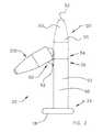
- FIG. 1is a perspective view of an intraurethral device 20 in accordance with the present invention.
- Intraurethral device 20includes a sheath 22 having a distal portion 26 and a proximal portion 24.
- Sheath 22also includes a proximal retainer 28 disposed proximate it's proximal portion 24.
- Proximal retainer 28serves to prevent distal motion of sheath 22 into the patient by lying against the urethral labia.
- Sheath 22includes a sheath wall 32 defining a central lumen 30.
- a flow control valve unit 40is disposed in lumen 30 of sheath 22.
- Two examples of flow control valve assemblies which are suitable for inclusion in valve housing 40are described by Kulisz et al. in U.S. Patent No. 5,437,604 entitled NONSURGICAL INTRAURETHRAL BLADDER CONTROL DEVICE, and U.S. Patent Application Serial No. 09/207,821 by Migachyov and entitled VALVE FOR BLADDER CONTROL DEVICE.
- Those of skill in the artwill appreciate that other flow control valves may be used in conjunction with intraurethral device 20 without departing from the scope of the present invention as defined in the claims.
- Proximal region 24 of sheath 22includes a proximal lock 42 having recesses or cavities 44. Recesses 44 are adapted to receive a flange portion 48 of flow control valve unit 40.
- a distal stop 46lies in distal region 26 of sheath 22 for arresting the distal movement of flow control valve unit 40.
- Sheath walls 32are preferably formed of an elastomeric material such that a tubular flow control valve unit inserted within lumen 30 is partially held in position by a friction fit between the elastically stretched sheath walls 32 and the outside walls of the inserted flow control valve and/or by a medical grade adhesive.
- Intraurethral device 20also includes a distal member 50 having a distal tip 52 and a proximal portion 54.
- Proximal portion 54 of distal member 50is fixed to distal portion 26 of sheath 22 by a linking means 60.
- linking means 60includes an elastomer hinge 62.
- intraurethral device 20When no external force is applied to elastomer hinge 62, intraurethral device 20 assumes the position illustrated in Figure 1. Intraurethral device 20 may be selectively placed in other positions by deforming elastomer hinge 62. For example, distal member 50 may be urged into axial alignment with sheath 22. When intraurethral device 20 is in the position shown in Figure 1, distal member 50 serves to prevent proximal motion of sheath 22 out of the patient by contacting the bladder floor. Two exemplary positions of distal member 50 are best illustrated in Figure 2.
- Figure 2is a plan view of intraurethral device 20 with an axially aligned position of distal member 50 shown with phantom lines.
- the axially aligned position of distal member 50is generally designated by the number 100.
- intraurethral device 20is urged into position 100 to aid in inserting intraurethral device 20 into a urethra.
- intraurethral device 20assumes a second position 200 as shown in Figure 2.
- distal member 50serves to prevent proximal motion of sheath 22 out of the patient by contacting the bladder floor.
- intraurethral device 20is inserted into the urethra of a patient until distal member 50 is free to assume a second position similar to position 200.
- elastomer hinge 62may be deformed in varying degrees to achieve any number of second positions of distal member 50.
- sheath 22, distal member 50, and elastomer hinge 62are all comprised of the same material.
- a presently preferred method of manufacturing this preferred embodimentis injection molding. Materials which may be suitable for this preferred embodiment include implantable grade silicone rubber, and thermoplastic rubber. Single piece construction simplifies assembly and reduces the possibility of any device components separating during residence in the patient
- Embodiments of intraurethral device 20have also been envisioned which include a surface layer 90.
- Surface layer 90may include an anti-microbial chemical agent such as chlorhexidine gluconate (CHG) or silver compounds to reduce the likelihood of infection during use.
- Surface layer 90may also include materials such as hyaluronic acid, a hydrogel, or other materials to mimic mucous.
- Surface layer 90may also include a lubricious material such as a hydrophilic hydrogel or a hydrophobic silicone to facilitate insertion and removal. It is envisioned that one or more of the above described surface layer materials can be used.
- Embodiments of intraurethral device 20have also been envisioned having a distal member 50 and a sheath 22 which are comprised of a material which includes the materials described above.
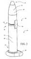
- Figure 3is a perspective view of intraurethral device 20 with distal member 50 in axial alignment with sheath 22.
- distal member 50preferably has a rounded shape to ease insertion through the urethra.
- the outer diameter of distal member 50is substantially equal to the outer diameter of sheath 22.
- distal member 50is urged into position 100 when inserting sheath 22 into the urethra.
- This methodmay now be described with reference to Figures 1, 2, and 3. It should be understood that steps may be omitted from this process and/or, the sequence of the steps may be changed without deviating from the spirit or scope of the invention.
- a presently preferred method in accordance with the present inventionbegins with the step of inserting distal member 50 into a female urethra. Intraurethral device 20 is then urged into position 100 as shown in Figures 2 and 3. The remainder of intraurethral device 20 including sheath 22 may then be urged into the female urethra. In many cases it is desirable to apply a lubricant to the exterior surfaces of distal member 50 and sheath 22 prior to insertion. During this insertion step, the urethra will hold intraurethral device 20 in position 100 until distal portion 50 enters the bladder. After distal portion 50 of intraurethral device 20 enters the bladder, it will be free to assume position 200.
- distal member 50serves to prevent proximal motion of sheath 22 out of the patient by contacting the bladder floor.
- elastomer hinge 62is biased to place distal portion 50 in first position 200.
- FIG 4is a perspective view of an assembly including an intraurethral device 20 and an insertion tool 400.
- Insertion tool 400includes a shaft 402 having a distal end 404 and a proximal end 406.
- a distal portion 408 of insertion tool 400is disposed in lumen 30 of sheath 22.
- a lumen 30(shown in Figure 1) extends into proximal portion 54 of tip 52.
- Proximal portion 54 of distal member 50is fixed to distal portion 26 of sheath 22 by a linking means 60.
- linking means 60includes an elastomer hinge 62.
- a distal end 404 of insertion tool 400is disposed in lumen 30 of distal member 50.
- distal member 50is held in axial alignment with sheath 22 by the presence of distal end 404 of shaft 402 in lumen 30 of distal member 50.
- a method of positioning an intraurethral device 20 into a urethra using insertion tool 400may now be described with reference to Figure 4.
- a first step desirable in some applicationsis to pre-lubricate and pre-dilate the urethra of the patient.
- the use of insertion tool 400begins with the step of inserting distal end 404 of shaft 402 into lumen 30 of sheath 22.
- Distal portion 50 of intraurethral device 20is then urged into axial alignment with sheath 22.
- lumen 30 of distal portion 50is disposed in axial alignment with lumen 30 of sheath 22.
- Insertion tool 400may then be urged forward so that distal end 404 enters lumen 430 of distal portion 50.
- insertion tool 400When insertion tool 400 is disposed within lumen 30 of sheath 22 and distal portion 50 it provides structural support. The structural support provided by insertion tool 400 improves the pushability of sheath 22 and distal member 50. Distal member 50 and sheath 22 may now be inserted into the urethra. In many cases it is desirable to apply a lubricant to the exterior surfaces of distal member 50 and sheath 22 prior to insertion.
- insertion tool 400may now be removed from lumen 30 of sheath 22. This may be accomplished by applying a pulling force on shaft 402 of insertion tool 400 while applying a pushing force on proximal retainer 28 of intraurethral device 20.
- distal portion 50 of intraurethral device 20will be free to assume position 200 as shown in Figure 2.
- distal member 50serves to prevent proximal motion of sheath 22 out of the patient by contacting the bladder floor. Distal motion of sheath 22 into the patient is prohibited by proximal retainer 28.
- flow control valve unit 40may now be inserted into lumen 30 of sheath 22.
- One method suitable for inserting a flow control valve unit into a sheathis described by Pham in U.S. Patent No. 5,871,016 entitled BLADDER CONTROL DEVICE RETAINER AND METHOD. This U.S. patent is commonly assigned with the present application.
- shaft 402 of insertion tool 400provides a convenient location to grasp with the fingers.
- the use of insertion tool 400minimizes the risk of infection by minimizing human contact with intraurethral device 20.
- distal end 404 of shaft 402is adapted to releasably mate with the proximal end of flow control valve unit 40.
- a method of inserting an intraurethral device 20 in a urethra utilizing this presently preferred embodiment of insertion tool 400may now be described with reference to Figures 1 and 4, This method typically begins with the step of inserting flow control valve 40 into lumen 30 of sheath 22.
- An additional step in this methodis releasably mating the distal end 404 of shaft 402 with the proximal end of flow control valve unit 40. In some instances, it may be desirable to reverse the order of these steps since insertion tool 400 may aid in inserting flow control valve unit 40 into lumen 30 of sheath 22.
- flange 48may be inserted into recesses 44.
- shaft 402 of insertion tool 400provides a convenient location to grasp the assembly. The use of insertion tool 400 minimizes the risk of infection by minimizing human contact with intraurethral device 20.
- Shaft 402 of insertion tool 400may be grasped with the physicians fingers to begin insertion of intraurethral device 20 into the urethra.
- Distal member 50 of intraurethral device 20may then be inserted into the urethra of the patient. Having positioned distal member 50 in the urethra, intraurethral device 20 is then urged into position 100 as shown in Figures 2 and 3. The remainder of intraurethral device 20 including sheath 22 may then be urged into the female urethra.
- the urethrawill hold intraurethral device 20 in position 100 until distal portion 50 enters the bladder. After distal portion 50 of intraurethral device 20 enters the bladder, it will be free to assume position 200.
- distal member 50serves to prevent proximal motion of sheath 22 out of the patient by contacting the bladder floor.
- elastomer hinge 62is biased to place distal portion 50 in first position 200.
- the distal end of insertion tool 400may be disengaged from the proximal end of flow control valve unit 40.
- a number of methodsmay be used to releasably mate distal end 404 of shaft 402 to the proximal end of the flow control valve unit 40. Examples of methods suitable for some applications include screw threads, a bayonet connection, and an interference fit.
- Intraurethral device 120includes a sheath 122 having a distal portion 126 and a proximal portion 124. Sheath 122 also includes a proximal retainer 128 disposed proximate it's proximal portion 124. Sheath 122 includes a sheath wall 132 defining a central lumen 130, providing a fluid flow channel from a distal orifice 136 to a proximal orifice 134 in proximal region 124.
- a flow control valve unit 140is disposed in lumen 130 of sheath 122.
- Proximal region 124includes a proximal lock 142 having recesses or cavities 144. Recesses 144 are adapted to receive a flange portion 148 of flow control valve unit 140.
- a distal stop 146lies in distal region 126 for arresting the distal movement of flow control valve unit 140.
- Sheath walls 132are preferably formed of an elastomeric material such that a tubular flow control valve unit inserted within lumen 130 is partially held in position by a friction fit between the elastically stretched sheath walls 132 and the outside walls of the inserted flow control valve.
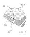
- Intraurethral device 120also includes a distal member 150 having a distal tip 152 and a proximal portion 154. Proximal portion 154 of distal member 150 is fixed to distal portion 126 of sheath 122 by a linking means 160.
- linking means 160includes a leaf spring 500.
- leaf spring 500is comprised of stainless steel. Those of skill in the art will appreciate that leaf spring 500 may be comprised of other materials without deviating from the spirit and scope of the present invention.
- Intraurethral device 120assumes the position illustrated in Figure 5, whenever no outside forces are acting upon leaf spring 500. Intraurethral device 120 may be selectively placed in other positions by applying force to deform leaf spring 500. For example, distal member 150 may be urged into axial alignment with sheath 122. When intraurethral device 120 is in the position shown in Figure 5, distal member 150 serves to prevent proximal motion of sheath 122 out of the patient by contacting the bladder floor. Distal member 150 may be selectively positioned in axial alignment with sheath 122.
- distal member 150 and leaf spring 500are fixed together using an over molding process.
- a distal portion of leaf spring 500is positioned in a mold cavity.
- the material of distal member 150is then injected into the mold cavity.
- the material of distal member 150surrounds distal portion of leaf spring 500. When the material solidifies, it forms a bond with distal portion of leaf spring 500.
- Materials which may be suitable for this preferred embodimentinclude thermoset materials such as implantable grade silicone rubber. Materials which may be suitable for this preferred embodiment also include thermoplastic materials such as thermoplastic rubber.
- a proximal portion of leaf spring 500is fixed to sheath 122.
- a number of methodsmay be used to attach proximal portion 504 to sheath 122, including over-molding, adhesive bonding, and mechanical attachment. Additional embodiments have been envisioned in which proximal portion of leaf spring 500 is fixed to flow control valve unit 140.
- distal portion 150 of intraurethral device 120When insertion tool 400 is removed, distal portion 150 of intraurethral device 120 will be free to assume position 200 as shown in Figure 2. When intraurethral device 120 assumes position 200, distal member 150 serves to prevent proximal motion of sheath 122 out of the patient by contacting the bladder floor. Distal motion of sheath 122 into the patient is prohibited by proximal retainer 128.
- intraurethral device 20is shown after placement in the urethra of the patient and after whatever placement devices which were used have been removed and the urethra has undilated to closely hold and form to the outer surface of intraurethral device 20. It can be appreciated that after intraurethral device 20 is placed in the desired position distal portion 50 of intraurethral device 20 assumes a position which is not in axial alignment with sheath 22. When intraurethral device 20 assumes such a position, distal member 50 serves to prevent proximal motion of sheath 22 out of the patient by contacting the bladder floor.
- proximal retainer 28Distal motion of sheath 22 into the patient is prohibited by proximal retainer 28 which contacts the labia of the urethra. In this manner, intraurethral device 20 is held within the urethra by distal member 50 and proximal retainer 28 acting at opposite ends of the urethra.
Landscapes
- Health & Medical Sciences (AREA)
- Vascular Medicine (AREA)
- General Health & Medical Sciences (AREA)
- Oral & Maxillofacial Surgery (AREA)
- Transplantation (AREA)
- Engineering & Computer Science (AREA)
- Biomedical Technology (AREA)
- Heart & Thoracic Surgery (AREA)
- Urology & Nephrology (AREA)
- Cardiology (AREA)
- Life Sciences & Earth Sciences (AREA)
- Animal Behavior & Ethology (AREA)
- Public Health (AREA)
- Veterinary Medicine (AREA)
- Prostheses (AREA)
- Endoscopes (AREA)
- Pharmaceuticals Containing Other Organic And Inorganic Compounds (AREA)
- External Artificial Organs (AREA)
- Saccharide Compounds (AREA)
Abstract
Description
Claims (9)
- A female intraurethral device (20, 120) for containing a urinary now controlvalve unit (40; 140) comprising:a sheath (22; 122) having a distal portion (26; 126), a proximal portion (24; 124), and a lumentherethrough;a distal member (50; 150) having a proximal portion (54; 154) defining a lumen (30; 130);a linking member (60) having a distal end and a proximal end;the distal end of the linking member being fixed to the proximal end (54; 154) of thedistal member (50; 150), andthe proximal end of the linking member being fixed to the distal end (26; 126) of thesheath (20; 122); and the axis of the distal member being disposed at an angle to the axis of the sheath.
- A female intraurethral device as recited in claim 1, wherein thelinking member (60) is comprised of a flexible material.
- A female intraurethral device as recited in claim 1 or 2, wherein thelinking member (60) is comprised of an elastomeric material.
- A female intraurethral device as recited in any of claims 1 to 3, wherein thedistal member (50; 150) has a first, outwardly extended position, and second, longitudinallyextended position.
- A female intraurethral sheath as recited in any of claims 1 to 4, wherein thedistal member (50; 150) and the linking member are integrally formed with the sheath.
- A female intraurethral sheath as recited in any of claims 1 to 5, wherein thesheath (22; 122), the distal member (50; 150), and the linking member are all comprised of siliconerubber.
- A female intraurethral sheath as recited in any of claims 1 to 5, wherein thesheath (22; 122), the distal member (50; 150), and the linking member are all comprised ofthermoplastic rubber.
- A female intraurethral device as recited in any of claims 1 to 7, wherein a flowcontrol valve is disposed within said sheath lumen.
- A female intraurethral device as recited in any of claims 1 to 8, wherein thedistal member (50; 150) includes a generally conical distal tip.
Applications Claiming Priority (3)
| Application Number | Priority Date | Filing Date | Title |
|---|---|---|---|
| US30285699A | 1999-04-30 | 1999-04-30 | |
| US302856 | 1999-04-30 | ||
| PCT/US2000/011502WO2000066054A1 (en) | 1999-04-30 | 2000-04-28 | Intraurethral device and method |
Publications (3)
| Publication Number | Publication Date |
|---|---|
| EP1191902A1 EP1191902A1 (en) | 2002-04-03 |
| EP1191902A4 EP1191902A4 (en) | 2002-09-11 |
| EP1191902B1true EP1191902B1 (en) | 2005-03-09 |
Family
ID=23169498
Family Applications (1)
| Application Number | Title | Priority Date | Filing Date |
|---|---|---|---|
| EP00931967AExpired - LifetimeEP1191902B1 (en) | 1999-04-30 | 2000-04-28 | Intraurethral device |
Country Status (8)
| Country | Link |
|---|---|
| US (3) | US6676593B2 (en) |
| EP (1) | EP1191902B1 (en) |
| JP (1) | JP2002542893A (en) |
| AT (1) | ATE290349T1 (en) |
| CA (1) | CA2372204A1 (en) |
| DE (1) | DE60018566T2 (en) |
| ES (1) | ES2239008T3 (en) |
| WO (1) | WO2000066054A1 (en) |
Cited By (5)
| Publication number | Priority date | Publication date | Assignee | Title |
|---|---|---|---|---|
| US7235043B2 (en) | 2001-03-09 | 2007-06-26 | Boston Scientific Scimed Inc. | System for implanting an implant and method thereof |
| US7402133B2 (en) | 2002-12-17 | 2008-07-22 | Boston Scientific Scimed, Inc. | Spacer for sling delivery system |
| US8016741B2 (en) | 2005-04-06 | 2011-09-13 | Boston Scientific Scimed, Inc. | Systems, devices, and methods for sub-urethral support |
| US8033983B2 (en) | 2001-03-09 | 2011-10-11 | Boston Scientific Scimed, Inc. | Medical implant |
| US8628465B2 (en) | 2004-06-14 | 2014-01-14 | Boston Scientific Scimed, Inc. | Systems, methods and devices relating to implantable supportive slings |
Families Citing this family (11)
| Publication number | Priority date | Publication date | Assignee | Title |
|---|---|---|---|---|
| US6183413B1 (en)* | 1998-12-09 | 2001-02-06 | Hk Medical Technologies Incorporated | Valve for bladder control device |
| EP1191902B1 (en)* | 1999-04-30 | 2005-03-09 | HK Medical Technologies Incorporated | Intraurethral device |
| US6666817B2 (en) | 2001-10-05 | 2003-12-23 | Scimed Life Systems, Inc. | Expandable surgical implants and methods of using them |
| WO2007008209A1 (en) | 2005-07-13 | 2007-01-18 | Boston Scientific Scimed Inc. | Snap fit sling anchor system and related methods |
| EP2974692B1 (en) | 2005-07-25 | 2019-03-13 | Boston Scientific Limited | Pelvic floor repair system |
| DE102008033002A1 (en)* | 2008-07-14 | 2010-01-21 | Markus Schedler | Device for producing urinary continence with reduced effect of female bladder closing muscles, has bladder anchor, urethra stab and supporting device, where urethra stab is formed such that device is disposed in urethra |
| US9113991B2 (en) | 2011-05-12 | 2015-08-25 | Boston Scientific Scimed, Inc. | Anchors for bodily implants and methods for anchoring bodily implants into a patient's body |
| US9636201B2 (en) | 2011-05-12 | 2017-05-02 | Boston Scientific Scimed, Inc. | Delivery members for delivering an implant into a body of a patient |
| ITPI20120025A1 (en) | 2012-03-17 | 2013-09-18 | Giuliani Giuseppe | STRUCTURE OF ENETURETHRAL URETHRO-VESICAL BORDER |
| US11246693B2 (en) | 2019-09-18 | 2022-02-15 | David Hesse | Urinary plug device |
| US11583666B2 (en) | 2019-09-18 | 2023-02-21 | David Hesse | Device and methods for treating urothelial conditions |
Family Cites Families (36)
| Publication number | Priority date | Publication date | Assignee | Title |
|---|---|---|---|---|
| US3628530A (en) | 1969-03-24 | 1971-12-21 | Jerome Schwartz | Intrauterine device for contraception |
| US3642004A (en) | 1970-01-05 | 1972-02-15 | Life Support Equipment Corp | Urethral valve |
| US3812841A (en) | 1972-08-21 | 1974-05-28 | L Isaacson | Urethra magnetic valve structure |
| US4246896A (en) | 1978-10-30 | 1981-01-27 | Dynatech Corp. | Intracervical cuff (ICC) for contraception and prevention of venereal disease and applicator therefor |
| US4553533A (en) | 1983-11-08 | 1985-11-19 | Leighton Stephen B | Intra-urethral prosthetic sphincter valve |
| US5112306A (en) | 1986-03-25 | 1992-05-12 | American Medical Systems, Inc. | Method and apparatus for valving body fluids |
| US5123428A (en) | 1988-10-11 | 1992-06-23 | Schwarz Gerald R | Laparoscopically implanting bladder control apparatus |
| US4969474A (en) | 1988-10-11 | 1990-11-13 | Schwarz Gerald R | Incontinence bladder control method and apparatus |
| AU4492989A (en) | 1988-10-20 | 1990-05-14 | Fusen H. Chen | Incontinence device |
| US5800339A (en) | 1989-02-09 | 1998-09-01 | Opticon Medical Inc. | Urinary control valve |
| US5234409A (en) | 1989-07-07 | 1993-08-10 | Cabot Technology Corporation | Female incontinence control device and method |
| US5041092A (en) | 1989-08-29 | 1991-08-20 | Medical Engineering Corporation | Urethral indwelling catheter with magnetically controlled drainage valve and method |
| FR2653993B1 (en) | 1989-11-03 | 1992-01-10 | Synthelabo | HYDRAULIC PRESSURE INVERTER FOR THE CONTROL OF AN ARTIFICIAL SPHINCTER, AND IMPLANTABLE PROSTHESIS COMPRISING SAID INVERTER. |
| US5114398A (en) | 1990-02-27 | 1992-05-19 | Medical Engineering Corporation | Female incontinence control device with mechanically operable valve |
| US5088980A (en) | 1990-05-31 | 1992-02-18 | The United States Of America As Represented By The Department Of Health And Human Services | Intra-urethral valve with integral spring |
| US5090424A (en) | 1990-12-31 | 1992-02-25 | Uromed Corporation | Conformable urethral plug |
| US5479945A (en) | 1990-12-31 | 1996-01-02 | Uromed Corporation | Method and a removable device which can be used for the self-administered treatment of urinary tract infections or other disorders |
| US5140999A (en) | 1991-09-30 | 1992-08-25 | Primed International Corp. | Urinary incontinence valve device |
| US5476434A (en) | 1992-05-27 | 1995-12-19 | Kalb; Irvin M. | Female incontinence device including electronic sensors |
| US5352182A (en)* | 1992-05-27 | 1994-10-04 | Kalb Irvin M | Product and method to treat female incontinence |
| US5512032A (en) | 1993-12-23 | 1996-04-30 | Hk Medical Technologies, Inc. | Nonsurgical intraurethral bladder control device |
| US5417226A (en) | 1994-06-09 | 1995-05-23 | Juma; Saad | Female anti-incontinence device |
| US5509888A (en) | 1994-07-26 | 1996-04-23 | Conceptek Corporation | Controller valve device and method |
| US5624374A (en) | 1994-11-03 | 1997-04-29 | Von Iderstein; Irwin F. | Involuntary urine control apparatus, system and method |
| IL111953A (en) | 1994-12-12 | 2012-04-30 | Medical Influence Technologies Ltd | Device for catheter fixation |
| US5624395A (en) | 1995-02-23 | 1997-04-29 | Cv Dynamics, Inc. | Urinary catheter having palpitatable valve and balloon and method for making same |
| JP3519511B2 (en) | 1995-07-27 | 2004-04-19 | ファナック株式会社 | Control method and apparatus for injection molding machine |
| US5701916A (en) | 1995-08-16 | 1997-12-30 | Hk Medical Technologies Incorporated | Intraurethral bladder control device with retainer apparatus |
| US5618257A (en)* | 1995-08-16 | 1997-04-08 | Hk Medical Technologies Incorporated | Bladder control insertion apparatus and method |
| US5713829A (en) | 1996-07-08 | 1998-02-03 | Fuji Tsu Limited | Female urinary incontinence device |
| US5795288A (en) | 1996-08-08 | 1998-08-18 | Cohen; Kenneth L. | Apparatus with valve for treating incontinence |
| US5749826A (en) | 1996-11-06 | 1998-05-12 | Faulkner; James W. | Urinary incontinence control device |
| US5711314A (en)* | 1996-11-08 | 1998-01-27 | Primed International Corporation | Urinary incontinence valve with distal and proximal anchoring means |
| US5806527A (en) | 1997-06-04 | 1998-09-15 | Borodulin; German | Urethral plug with means for protection against infection |
| US5871016A (en)* | 1997-10-08 | 1999-02-16 | Hk Medical Technologies Incorporated | Bladder control device retainer and method |
| EP1191902B1 (en)* | 1999-04-30 | 2005-03-09 | HK Medical Technologies Incorporated | Intraurethral device |
- 2000
- 2000-04-28EPEP00931967Apatent/EP1191902B1/ennot_activeExpired - Lifetime
- 2000-04-28CACA002372204Apatent/CA2372204A1/ennot_activeAbandoned
- 2000-04-28ESES00931967Tpatent/ES2239008T3/ennot_activeExpired - Lifetime
- 2000-04-28DEDE60018566Tpatent/DE60018566T2/ennot_activeExpired - Fee Related
- 2000-04-28ATAT00931967Tpatent/ATE290349T1/ennot_activeIP Right Cessation
- 2000-04-28WOPCT/US2000/011502patent/WO2000066054A1/enactiveIP Right Grant
- 2000-04-28JPJP2000614941Apatent/JP2002542893A/enactivePending
- 2001
- 2001-07-18USUS09/908,467patent/US6676593B2/ennot_activeExpired - Fee Related
- 2003
- 2003-11-03USUS10/699,989patent/US7241259B2/ennot_activeExpired - Fee Related
- 2007
- 2007-07-09USUS11/775,057patent/US20080015548A1/ennot_activeAbandoned
Cited By (11)
| Publication number | Priority date | Publication date | Assignee | Title |
|---|---|---|---|---|
| US7235043B2 (en) | 2001-03-09 | 2007-06-26 | Boston Scientific Scimed Inc. | System for implanting an implant and method thereof |
| US8033983B2 (en) | 2001-03-09 | 2011-10-11 | Boston Scientific Scimed, Inc. | Medical implant |
| US8162816B2 (en) | 2001-03-09 | 2012-04-24 | Boston Scientific Scimed, Inc. | System for implanting an implant and method thereof |
| US8617048B2 (en) | 2001-03-09 | 2013-12-31 | Boston Scientific Scimed, Inc. | System for implanting an implant and method thereof |
| US7402133B2 (en) | 2002-12-17 | 2008-07-22 | Boston Scientific Scimed, Inc. | Spacer for sling delivery system |
| US8632453B2 (en) | 2002-12-17 | 2014-01-21 | Boston Scientific Scimed, Inc. | Spacer for sling delivery system |
| US8628465B2 (en) | 2004-06-14 | 2014-01-14 | Boston Scientific Scimed, Inc. | Systems, methods and devices relating to implantable supportive slings |
| US10219885B2 (en) | 2004-06-14 | 2019-03-05 | Boston Scientific Scimed, Inc. | Systems, methods and devices relating to implantable supportive slings |
| US11918447B2 (en) | 2004-06-14 | 2024-03-05 | Boston Scientific Scimed, Inc. | Systems, methods and devices relating to implantable supportive slings |
| US8016741B2 (en) | 2005-04-06 | 2011-09-13 | Boston Scientific Scimed, Inc. | Systems, devices, and methods for sub-urethral support |
| US9022920B2 (en) | 2005-04-06 | 2015-05-05 | Boston Scientific Scimed, Inc. | Systems, devices, and methods for sub-urethral support |
Also Published As
| Publication number | Publication date |
|---|---|
| CA2372204A1 (en) | 2000-11-09 |
| ES2239008T3 (en) | 2005-09-16 |
| EP1191902A4 (en) | 2002-09-11 |
| US20040097786A1 (en) | 2004-05-20 |
| WO2000066054A1 (en) | 2000-11-09 |
| US7241259B2 (en) | 2007-07-10 |
| DE60018566D1 (en) | 2005-04-14 |
| DE60018566T2 (en) | 2006-04-13 |
| ATE290349T1 (en) | 2005-03-15 |
| JP2002542893A (en) | 2002-12-17 |
| US20010041822A1 (en) | 2001-11-15 |
| EP1191902A1 (en) | 2002-04-03 |
| US6676593B2 (en) | 2004-01-13 |
| US20080015548A1 (en) | 2008-01-17 |
Similar Documents
| Publication | Publication Date | Title |
|---|---|---|
| US20080015548A1 (en) | Intraurethral device and method | |
| US4676782A (en) | Positionable tissue interfacing device for the management of percutaneous conduits | |
| US5749826A (en) | Urinary incontinence control device | |
| US5724994A (en) | Fluidly expandable urethral plug assembly which receives fluid from an external source and method for controlling urinary incontinence | |
| US5090424A (en) | Conformable urethral plug | |
| EP0343953B1 (en) | Self-occluding intravascular cannula assembly | |
| US6929621B2 (en) | Drainage catheter with bifurcating tip | |
| US6152931A (en) | Medical device comprising a rod equipped with a means for absorbing axial stresses | |
| EP0798994B1 (en) | Urinary incontinence device | |
| US6231501B1 (en) | Urinary occlusion device | |
| AU765693B2 (en) | An access member and a system for catheterization of the urinary bladder through an artificial or a natural canal in a user, and a method of replacing such an access member | |
| NL9002710A (en) | METHOD FOR CONTROLLING INCONTINENCE IN WOMEN AND DEVICE FOR USING THIS METHOD | |
| US20220168006A1 (en) | Tool adapted to connect tubing of an implantable penile prosthesis | |
| JP7216712B2 (en) | Urethral plugs and systems for treating urinary incontinence | |
| US5871016A (en) | Bladder control device retainer and method | |
| US5996585A (en) | Nonsurgical intraurethral bladder control device retainer | |
| WO2000066029A1 (en) | Bladder control device and method for treating female urinary incontinence | |
| Elliott et al. | Urethral devices for managing stress urinary incontinence | |
| CN221431708U (en) | Catheter structure with magnetic valve | |
| US20240358404A1 (en) | Disposable furlow insertion device | |
| WO2024226427A1 (en) | Urinary catheter assembly with guidance device |
Legal Events
| Date | Code | Title | Description |
|---|---|---|---|
| PUAI | Public reference made under article 153(3) epc to a published international application that has entered the european phase | Free format text:ORIGINAL CODE: 0009012 | |
| 17P | Request for examination filed | Effective date:20011107 | |
| AK | Designated contracting states | Kind code of ref document:A1 Designated state(s):AT BE CH CY DE DK ES FI FR GB GR IE IT LI LU MC NL PT SE | |
| A4 | Supplementary search report drawn up and despatched | Effective date:20020726 | |
| AK | Designated contracting states | Kind code of ref document:A4 Designated state(s):AT BE CH CY DE DK ES FI FR GB GR IE IT LI LU MC NL PT SE | |
| RIC1 | Information provided on ipc code assigned before grant | Free format text:7A 61F 2/00 A, 7A 61M 1/00 B, 7A 61F 2/06 B | |
| 17Q | First examination report despatched | Effective date:20030120 | |
| GRAP | Despatch of communication of intention to grant a patent | Free format text:ORIGINAL CODE: EPIDOSNIGR1 | |
| RTI1 | Title (correction) | Free format text:INTRAURETHRAL DEVICE | |
| GRAS | Grant fee paid | Free format text:ORIGINAL CODE: EPIDOSNIGR3 | |
| GRAA | (expected) grant | Free format text:ORIGINAL CODE: 0009210 | |
| AK | Designated contracting states | Kind code of ref document:B1 Designated state(s):AT BE CH CY DE DK ES FI FR GB GR IE IT LI LU MC NL PT SE | |
| PG25 | Lapsed in a contracting state [announced via postgrant information from national office to epo] | Ref country code:FI Free format text:LAPSE BECAUSE OF FAILURE TO SUBMIT A TRANSLATION OF THE DESCRIPTION OR TO PAY THE FEE WITHIN THE PRESCRIBED TIME-LIMIT Effective date:20050309 Ref country code:AT Free format text:LAPSE BECAUSE OF FAILURE TO SUBMIT A TRANSLATION OF THE DESCRIPTION OR TO PAY THE FEE WITHIN THE PRESCRIBED TIME-LIMIT Effective date:20050309 Ref country code:BE Free format text:LAPSE BECAUSE OF FAILURE TO SUBMIT A TRANSLATION OF THE DESCRIPTION OR TO PAY THE FEE WITHIN THE PRESCRIBED TIME-LIMIT Effective date:20050309 | |
| REG | Reference to a national code | Ref country code:GB Ref legal event code:FG4D | |
| REG | Reference to a national code | Ref country code:CH Ref legal event code:EP | |
| REG | Reference to a national code | Ref country code:IE Ref legal event code:FG4D | |
| REF | Corresponds to: | Ref document number:60018566 Country of ref document:DE Date of ref document:20050414 Kind code of ref document:P | |
| PG25 | Lapsed in a contracting state [announced via postgrant information from national office to epo] | Ref country code:IE Free format text:LAPSE BECAUSE OF NON-PAYMENT OF DUE FEES Effective date:20050428 Ref country code:LU Free format text:LAPSE BECAUSE OF NON-PAYMENT OF DUE FEES Effective date:20050428 Ref country code:CY Free format text:LAPSE BECAUSE OF FAILURE TO SUBMIT A TRANSLATION OF THE DESCRIPTION OR TO PAY THE FEE WITHIN THE PRESCRIBED TIME-LIMIT Effective date:20050428 | |
| PG25 | Lapsed in a contracting state [announced via postgrant information from national office to epo] | Ref country code:SE Free format text:LAPSE BECAUSE OF NON-PAYMENT OF DUE FEES Effective date:20050429 | |
| PG25 | Lapsed in a contracting state [announced via postgrant information from national office to epo] | Ref country code:MC Free format text:LAPSE BECAUSE OF NON-PAYMENT OF DUE FEES Effective date:20050430 Ref country code:CH Free format text:LAPSE BECAUSE OF NON-PAYMENT OF DUE FEES Effective date:20050430 Ref country code:LI Free format text:LAPSE BECAUSE OF NON-PAYMENT OF DUE FEES Effective date:20050430 | |
| REG | Reference to a national code | Ref country code:SE Ref legal event code:TRGR | |
| PG25 | Lapsed in a contracting state [announced via postgrant information from national office to epo] | Ref country code:DK Free format text:LAPSE BECAUSE OF FAILURE TO SUBMIT A TRANSLATION OF THE DESCRIPTION OR TO PAY THE FEE WITHIN THE PRESCRIBED TIME-LIMIT Effective date:20050609 Ref country code:GR Free format text:LAPSE BECAUSE OF FAILURE TO SUBMIT A TRANSLATION OF THE DESCRIPTION OR TO PAY THE FEE WITHIN THE PRESCRIBED TIME-LIMIT Effective date:20050609 | |
| PG25 | Lapsed in a contracting state [announced via postgrant information from national office to epo] | Ref country code:PT Free format text:LAPSE BECAUSE OF FAILURE TO SUBMIT A TRANSLATION OF THE DESCRIPTION OR TO PAY THE FEE WITHIN THE PRESCRIBED TIME-LIMIT Effective date:20050907 | |
| REG | Reference to a national code | Ref country code:ES Ref legal event code:FG2A Ref document number:2239008 Country of ref document:ES Kind code of ref document:T3 | |
| PG25 | Lapsed in a contracting state [announced via postgrant information from national office to epo] | Ref country code:NL Free format text:LAPSE BECAUSE OF NON-PAYMENT OF DUE FEES Effective date:20051101 | |
| REG | Reference to a national code | Ref country code:CH Ref legal event code:PL | |
| NLV4 | Nl: lapsed or anulled due to non-payment of the annual fee | Effective date:20051101 | |
| PLBE | No opposition filed within time limit | Free format text:ORIGINAL CODE: 0009261 | |
| STAA | Information on the status of an ep patent application or granted ep patent | Free format text:STATUS: NO OPPOSITION FILED WITHIN TIME LIMIT | |
| EUG | Se: european patent has lapsed | ||
| ET | Fr: translation filed | ||
| 26N | No opposition filed | Effective date:20051212 | |
| PGFP | Annual fee paid to national office [announced via postgrant information from national office to epo] | Ref country code:ES Payment date:20070425 Year of fee payment:8 | |
| REG | Reference to a national code | Ref country code:FR Ref legal event code:ST Effective date:20070228 | |
| PGFP | Annual fee paid to national office [announced via postgrant information from national office to epo] | Ref country code:DE Payment date:20070531 Year of fee payment:8 | |
| REG | Reference to a national code | Ref country code:FR Ref legal event code:D3 | |
| PGFP | Annual fee paid to national office [announced via postgrant information from national office to epo] | Ref country code:GB Payment date:20070430 Year of fee payment:8 | |
| PGFP | Annual fee paid to national office [announced via postgrant information from national office to epo] | Ref country code:IT Payment date:20070629 Year of fee payment:8 | |
| PGFP | Annual fee paid to national office [announced via postgrant information from national office to epo] | Ref country code:FR Payment date:20070420 Year of fee payment:8 | |
| GBPC | Gb: european patent ceased through non-payment of renewal fee | Effective date:20080428 | |
| PG25 | Lapsed in a contracting state [announced via postgrant information from national office to epo] | Ref country code:DE Free format text:LAPSE BECAUSE OF NON-PAYMENT OF DUE FEES Effective date:20081101 | |
| REG | Reference to a national code | Ref country code:FR Ref legal event code:ST Effective date:20081231 | |
| PG25 | Lapsed in a contracting state [announced via postgrant information from national office to epo] | Ref country code:FR Free format text:LAPSE BECAUSE OF NON-PAYMENT OF DUE FEES Effective date:20080430 | |
| REG | Reference to a national code | Ref country code:ES Ref legal event code:FD2A Effective date:20080429 | |
| PG25 | Lapsed in a contracting state [announced via postgrant information from national office to epo] | Ref country code:GB Free format text:LAPSE BECAUSE OF NON-PAYMENT OF DUE FEES Effective date:20080428 | |
| PG25 | Lapsed in a contracting state [announced via postgrant information from national office to epo] | Ref country code:ES Free format text:LAPSE BECAUSE OF NON-PAYMENT OF DUE FEES Effective date:20080429 | |
| PG25 | Lapsed in a contracting state [announced via postgrant information from national office to epo] | Ref country code:IT Free format text:LAPSE BECAUSE OF NON-PAYMENT OF DUE FEES Effective date:20080428 |